JP2011016217A - Method for directly forming die cut by one etching, and die cut formed thereby - Google Patents
Method for directly forming die cut by one etching, and die cut formed thereby Download PDFInfo
- Publication number
- JP2011016217A JP2011016217A JP2009186588A JP2009186588A JP2011016217A JP 2011016217 A JP2011016217 A JP 2011016217A JP 2009186588 A JP2009186588 A JP 2009186588A JP 2009186588 A JP2009186588 A JP 2009186588A JP 2011016217 A JP2011016217 A JP 2011016217A
- Authority
- JP
- Japan
- Prior art keywords
- metal plate
- die cut
- etching
- corrosion
- blade
- Prior art date
- Legal status (The legal status is an assumption and is not a legal conclusion. Google has not performed a legal analysis and makes no representation as to the accuracy of the status listed.)
- Pending
Links
- 238000005530 etching Methods 0.000 title claims abstract description 81
- 238000000034 method Methods 0.000 title claims abstract description 56
- 229910052751 metal Inorganic materials 0.000 claims abstract description 87
- 239000002184 metal Substances 0.000 claims abstract description 87
- 229920002120 photoresistant polymer Polymers 0.000 claims abstract description 51
- 238000005260 corrosion Methods 0.000 claims abstract description 46
- 230000007797 corrosion Effects 0.000 claims abstract description 36
- 238000005507 spraying Methods 0.000 claims description 11
- 239000000463 material Substances 0.000 claims description 5
- 239000007788 liquid Substances 0.000 claims description 4
- 239000007769 metal material Substances 0.000 claims description 3
- 230000003647 oxidation Effects 0.000 claims description 3
- 238000007254 oxidation reaction Methods 0.000 claims description 3
- 229910052782 aluminium Inorganic materials 0.000 claims description 2
- XAGFODPZIPBFFR-UHFFFAOYSA-N aluminium Chemical compound [Al] XAGFODPZIPBFFR-UHFFFAOYSA-N 0.000 claims description 2
- 238000005238 degreasing Methods 0.000 claims 1
- 230000015572 biosynthetic process Effects 0.000 abstract 1
- 238000007517 polishing process Methods 0.000 abstract 1
- 238000005498 polishing Methods 0.000 description 5
- 229910000975 Carbon steel Inorganic materials 0.000 description 4
- 239000010962 carbon steel Substances 0.000 description 4
- 239000007921 spray Substances 0.000 description 4
- 238000012986 modification Methods 0.000 description 3
- 230000004048 modification Effects 0.000 description 3
- 239000007787 solid Substances 0.000 description 3
- 238000004528 spin coating Methods 0.000 description 3
- 239000000126 substance Substances 0.000 description 3
- XLYOFNOQVPJJNP-UHFFFAOYSA-N water Substances O XLYOFNOQVPJJNP-UHFFFAOYSA-N 0.000 description 3
- 238000004519 manufacturing process Methods 0.000 description 2
- 239000002253 acid Substances 0.000 description 1
- 239000011248 coating agent Substances 0.000 description 1
- 238000000576 coating method Methods 0.000 description 1
- 239000004744 fabric Substances 0.000 description 1
- 239000006260 foam Substances 0.000 description 1
- 239000010985 leather Substances 0.000 description 1
- 238000003801 milling Methods 0.000 description 1
- 239000005022 packaging material Substances 0.000 description 1
- 238000005192 partition Methods 0.000 description 1
Images


Classifications
-
- B—PERFORMING OPERATIONS; TRANSPORTING
- B44—DECORATIVE ARTS
- B44C—PRODUCING DECORATIVE EFFECTS; MOSAICS; TARSIA WORK; PAPERHANGING
- B44C1/00—Processes, not specifically provided for elsewhere, for producing decorative surface effects
- B44C1/22—Removing surface-material, e.g. by engraving, by etching
- B44C1/227—Removing surface-material, e.g. by engraving, by etching by etching
-
- B—PERFORMING OPERATIONS; TRANSPORTING
- B44—DECORATIVE ARTS
- B44B—MACHINES, APPARATUS OR TOOLS FOR ARTISTIC WORK, e.g. FOR SCULPTURING, GUILLOCHING, CARVING, BRANDING, INLAYING
- B44B5/00—Machines or apparatus for embossing decorations or marks, e.g. embossing coins
- B44B5/02—Dies; Accessories
- B44B5/026—Dies
Landscapes
- Engineering & Computer Science (AREA)
- Mechanical Engineering (AREA)
- Perforating, Stamping-Out Or Severing By Means Other Than Cutting (AREA)
- ing And Chemical Polishing (AREA)
- Moulds For Moulding Plastics Or The Like (AREA)
Abstract
Description
本発明はエッチングによりダイカットを形成する方法に関し、特に一回のエッチングによりダイカットを直接形成する方法に関するものである。 The present invention relates to a method of forming a die cut by etching, and more particularly to a method of directly forming a die cut by a single etching.
エッチング・ダイカットは、主に、例えば紙、フィルム、フォーム(foam)、軟磁石シート、写真、皮、布等のシート材質のカッティングに利用され、所定のパターンや字形を形成したり、シート表面に浮き彫り字パターン又は字形をエンボス加工したりして、例えばカード、アルバムや包装材等の作成に用いられる。 Etching and die-cutting is mainly used for cutting sheet materials such as paper, film, foam, soft magnet sheet, photograph, leather, cloth, etc. to form a predetermined pattern or letter shape on the sheet surface. Embossed embossed patterns or shapes are used to create cards, albums, packaging materials, etc., for example.
一般的に、エッチング・ダイカットを製造する方法は主に2つある。一つは、金属板表面に、必要なパターン又は字形に応じて耐酸インクラインを印刷することにより、該金属表面をエッチング領域と非エッチング領域とに区画させるものであり、インクが乾燥した後、金属板をエッチング薬液に浸漬させることにより、金属表面におけるインクが印刷されていない領域は薬液のエッチングにより陥没部分に形成され、インクが印刷されている領域については薬液によってエッチングされていないため、突出部に形成される。この後、該突出部を研磨機又はミリングマシーンによりブレード部分として形成する。金属がエッチング液に浸漬された場合、インクラインの幅が不充分であれば、サイドエッチングの影響により、インクそのものは支持力の弱まりにより崩壊し、インクラインの精密度が制限されてしまう。一方、このような方法は、研磨機の寸法にも制限があるため、自由で繊細なパターンを作成することができず、しかも製造工程は非常に手間がかかることがあった。 In general, there are mainly two methods for manufacturing an etching die cut. One is to partition the metal surface into an etched area and a non-etched area by printing an acid-resistant ink line on the surface of the metal plate according to a necessary pattern or shape, and after the ink is dried, By immersing the metal plate in the etching chemical solution, the area where the ink is not printed on the metal surface is formed in the recessed portion by etching the chemical liquid, and the area where the ink is printed is not etched by the chemical liquid, Formed in the part. Thereafter, the protruding portion is formed as a blade portion by a polishing machine or a milling machine. When the metal is immersed in the etching solution, if the width of the ink line is insufficient, the ink itself collapses due to the weak support force due to the influence of side etching, and the accuracy of the ink line is limited. On the other hand, since the size of the polishing machine is limited in such a method, it is not possible to create a free and delicate pattern, and the manufacturing process may be very time-consuming.
特許文献1及び特許文献2には「エッチング液の吹き付けによりエッチングを行う方法として、まず、金属板表面にブレード原型をエッチング形成し、インク又はフォトレジストを除去した後、ブレード部分に対して第2回のエッチングを行い、紙を切断できるブレードを形成する」ことが開示されているが、エッチング液を吹き付ける圧力及びサイドエッチングによる衝撃は、インク又はフォトレジストラインに影響を及ぼすため、高精密度のインク又はフォトレジストラインを効果的に制御しエッチングを行うことができない。紙等のようなシートを切断できるブレードを形成するためには、インク又はフォトレジストを除去した後、ブレード原型部分に対して第2回のエッチングを行わなければならない。しかし、この第2回のエッチングによりブレードの先端が侵食され、ブレードの高さが不均一になり、切断効果に影響を及ぼしてしまい、しかも該方法はエッチング液の残留による水止め現象をいまだに克服できないため、ブレードとダイカットとの接続箇所では底部エッチングにより影響され、高精密度のダイカットの歩留まりが低下してしまう欠点があった。 In Patent Document 1 and Patent Document 2, “as a method of performing etching by spraying an etching solution, first, a blade prototype is formed by etching on the surface of a metal plate, ink or photoresist is removed, and then a second portion is applied to the blade portion. It is disclosed that a blade that can cut paper is formed by performing a single etching, but the pressure of spraying the etching liquid and the impact caused by side etching affect the ink or the photoresist line. Ink or photoresist lines cannot be effectively controlled and etched. In order to form a blade capable of cutting a sheet such as paper, after removing the ink or the photoresist, a second etching must be performed on the blade original part. However, the tip of the blade is eroded by the second etching, the height of the blade becomes non-uniform, affecting the cutting effect, and the method still overcomes the water stop phenomenon due to residual etching solution. Since this is not possible, the connection between the blade and the die cut is affected by the bottom etching, and the yield of the high precision die cut is reduced.
このため、高精密度のダイカットを形成するとともに、エッチング液によるサイドエッチングや水止め現象という欠点を回避することができる、ダイカットを直接形成する方法は重要な課題となっている。 For this reason, a method of directly forming a die cut that can form a high precision die cut and avoid the disadvantages of side etching and water stoppage due to an etching solution is an important issue.
上記の課題を解決するために、本発明では、(A)金属板を選択する工程と、(B)該金属板に耐腐食フォトレジストを2層形成し、露光、現像によりパターン化ラインを形成する工程と、(C)該金属板表面に対してエッチング液を吹き付けてエッチングを行うことでブレードを形成する工程と、(D)該耐腐食フォトレジストを除去する工程とを備えている、一回のエッチングによりダイカットを直接形成する方法が提供されている。本発明に係る方法は、耐腐食フォトレジストを2層形成し、ブレード部分としてエッチング形成しているため、エッチングの後に研磨又はポリシング加工を行う必要がなく、ブレード部分に対して二回のエッチングを行うこともなく、高精密度のダイカットを形成することができ、形成したダイカットの刀刃公差を低下させ、ダイカットの歩留まりを効果的に向上させることができる。 In order to solve the above problems, in the present invention, (A) a step of selecting a metal plate, and (B) two layers of corrosion resistant photoresist are formed on the metal plate, and a patterned line is formed by exposure and development. A step of forming a blade by performing etching by spraying an etching solution onto the surface of the metal plate, and (D) a step of removing the corrosion-resistant photoresist. There is provided a method of directly forming a die cut by multiple etchings. In the method according to the present invention, two layers of anti-corrosion photoresist are formed and etched as a blade portion. Therefore, it is not necessary to perform polishing or polishing after the etching, and the blade portion is etched twice. Without performing this, it is possible to form a die cut with a high degree of precision, reduce the sword blade tolerance of the formed die cut, and effectively improve the die cut yield.
さらに、本発明では、ダイカットのベースと該ダイカットベースに形成されたブレードとを備え、該ブレード先端表面が金属素材表皮のままに維持されている、一回のエッチングにより直接形成されたダイカットが提供されている。 Furthermore, the present invention provides a die-cut formed directly by a single etching, comprising a die-cut base and a blade formed on the die-cut base, the blade tip surface being maintained as a metal material skin. Has been.
下記において特定の具体的な実施例により本発明の実施方式を説明する。明細書に記載の内容は、この技術分野に精通した者なら簡単に本発明のその他の利点や効果が理解できる。本発明は、その他の異なる実施例によって施行や応用を加えることが可能であり、明細書に記載の内容も異なる観点や応用に基づき、本発明の精神を脱しない範囲で様々な修飾や変更が可能であり、そうした修飾や変更は本願の特許請求の範囲に含まれるものである。 In the following, specific embodiments of the present invention will be described with reference to specific embodiments. Those skilled in the art can easily understand the other advantages and effects of the present invention described in the specification. The present invention can be implemented and applied by other different embodiments, and various modifications and changes can be made without departing from the spirit of the present invention based on different viewpoints and applications. Such modifications and variations are intended to be included within the scope of the appended claims.
図1は、本発明に係る一回のエッチングによりダイカットを直接形成する方法の主要工程を示し、(a)金属板を選択する工程と、(b1)該金属板表面に第1の耐腐食フォトレジスト層を形成する工程と、(b2)所定のパターン又は字形を有するネガフィルムにより露光を行い、現像させた後、該金属板表面にパターン化された第1のラインを形成する工程と、(c1)該金属板表面に第1のラインを被覆する第2の耐腐食フォトレジストを形成する工程と、(c2)所定のパターン又は字形を有するネガフィルムにより露光を行い、現像させた後、該金属板表面に第1のラインを被覆するパターン化された第2のラインを形成する工程と、又は(c1’及びc2’)第2の耐腐食フォトレジストを直接印刷することで第1のラインを被覆するパターン化された第2のラインを形成する工程と、(d)該金属板表面へエッチング液を吹き付ける工程と、(e)該金属板表面から耐腐食フォトレジストを除去する工程と、を備えている。本発明に係る方法によれば、該第1及び第2の耐腐食フォトレジストを塗布又は印刷により該金属板表面に形成しても良いし、直接にドライ膜を金属板表面に貼り付けても良い。一方、金属板表面に耐腐食フォトレジストを形成する前に、従来の一般の技術により金属板表面の脱脂処理を予め行うことができる。また、金属板表面の耐腐食フォトレジストを除去した後、形成されたダイカットのブレードが酸化によって鈍化してしまうことを回避するために、耐酸化加工処理を行っても良い。 FIG. 1 shows the main steps of a method of directly forming a die cut by a single etching according to the present invention: (a) a step of selecting a metal plate; and (b1) a first corrosion-resistant photo on the surface of the metal plate. A step of forming a resist layer, and (b2) a step of forming a first line patterned on the surface of the metal plate after exposure and development with a negative film having a predetermined pattern or shape, c1) a step of forming a second anticorrosion photoresist covering the first line on the surface of the metal plate, and (c2) exposure and development with a negative film having a predetermined pattern or shape, Forming a patterned second line covering the first line on the surface of the metal plate; or (c1 ′ and c2 ′) by directly printing a second anti-corrosion photoresist Covered Forming a patterned second line to be performed; (d) spraying an etching solution onto the surface of the metal plate; and (e) removing a corrosion-resistant photoresist from the surface of the metal plate. ing. According to the method of the present invention, the first and second corrosion-resistant photoresists may be formed on the surface of the metal plate by coating or printing, or a dry film may be directly attached to the surface of the metal plate. good. On the other hand, before forming the corrosion resistant photoresist on the surface of the metal plate, the metal plate surface can be degreased by a conventional general technique. Further, after removing the corrosion-resistant photoresist on the surface of the metal plate, an oxidation-resistant processing treatment may be performed in order to prevent the formed die-cut blade from being blunted by oxidation.
(第1の実施例)
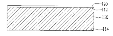
図2Aないし図2Gは、本発明に係る方法の第1の具体的な実施例を示す。図2Aに示すように、炭素鋼金属板110をダイカット金属板として使用し、該金属板110はブレードが形成される第1の表面112と該第1の表面112の反対側にある第2の表面114とを有している。ローラーにより該金属板110の第1の表面112にインクを被覆し第1の耐腐食フォトレジスト層120を形成する。パターン又は字形を有するネガフィルムにより露光、現像を行った後、図2Bに示すように、金属板110の第1の表面112に幅が所定の刀刃に相当するパターン化された第1のライン122を形成する。上述した工程を繰り返し、図2Cに示すように、金属板110の第1の表面112に、第1のライン122を被覆する第2の耐腐食フォトレジスト層130を形成する。図2Dに示すように、ネガフィルムにより露光、現像を再び行った後、金属板110の第1の表面112に第1のライン122を被覆するパターン化された第2のライン132を形成する。
(First embodiment)
2A to 2G show a first specific embodiment of the method according to the invention. As shown in FIG. 2A, a carbon
本発明に係る方法では、耐腐食フォトレジストを2層使用し、幅が刀刃に相当する第1のライン122をまず形成して、幅が刀刃より略大きく該第1のライン122を被覆する第2のライン132を形成する。図2Eに示すように、金属板の第1の表面112へエッチング液を吹き付ける場合、まず第2のライン132のパターン又は字形の幅をエッチング型板として使用し、ダイカットのブレード原型140をエッチング形成する。図2Fに示すように、エッチング液を一定の時間吹き付け続けることで、金属板表面の第2のライン132がエッチング液の吹き付けやサイドエッチングの衝撃により徐々に崩壊し、その中に被覆された第1のライン122が露出し、引き続き第1のライン122のパターン又は字形幅をエッチングブレードとして使用し、最終的にはダイカットに必要な高精密度ブレード150をエッチング形成する。最後に、図2Gに示すように、金属板の第1の表面112から耐腐食フォトレジストを除去することで高精密度ブレードを有するダイカットを形成する。
In the method according to the present invention, the
本発明に係る方法により形成されたダイカットは、ダイカットベースと、該ベースに形成されたブレード150とを備えている。本発明に係る方法では、一回のエッチングによりブレードを直接形成した後、機械又はCNC研磨を行う必要がなく、フォトレジストを除去した後もブレード部分に対して二回のエッチングを行うこともなくなる。従って、本発明に係る方法により形成されたダイカットは、ブレードの高さが0.5mm以上、好ましくは0.7mm以上であり、しかもブレードの先端112が金属素材のままであるため、二回のエッチングによりブレードの高さが不均一になるという欠点を回避するとともに、ダイカットの歩留まりを効果的に向上させることができる。
A die cut formed by the method according to the present invention includes a die cut base and a
(第2の実施例)
図3Aないし図3Gは、本発明に係る方法の第2の具体的な実施例を示す。図3Aに示すように、炭素鋼金属板210は、ブレードが形成される第1の表面212と該第1の表面212の反対側にある第2の表面214とを有している。スピンコーティングにより該金属板210の第1の表面212に第1の耐腐食フォトレジスト層220を形成する。パターン又は字形を有するネガフィルムにより露光、現像を行った後、図3Bに示すように、金属板210の第1の表面212に幅が所定の刀刃に相当するパターン化された第1のライン222を形成する。上述した工程を繰り返し、図3Cに示すように、金属板210の第1の表面212に、第1のライン222を被覆する第2の耐腐食フォトレジスト層230を形成する。図3Dに示すように、ネガフィルムにより露光、現像を再び行った後、金属板210の第1の表面212に第1のライン222を被覆するパターン化された第2のライン232を形成する。
(Second embodiment)
3A to 3G show a second specific embodiment of the method according to the invention. As shown in FIG. 3A, the carbon
図3Eに示すように、金属板210は、第1の表面212がフェースダウンでエッチングを行い、エッチング液を底部から上へ金属板の第1の表面212に向けて直接吹き付ける場合、まず第2のライン232のパターン又は字形の幅をエッチング型板として使用し、ダイカットのブレード原型240をエッチング形成する。図3Fに示すように、エッチング液を一定の時間吹き付け続けることで、金属板表面の第2のライン232がエッチング液の吹き付けやサイドエッチングの衝撃により徐々に崩壊し、その中に被覆された第1のライン222が露出し、引き続き第1のライン222のパターン又は字形幅をエッチングブレードとして使用し、最終的にはダイカットに必要な高精密度ブレード250をエッチング形成する。最後に、図3Gに示すように、金属板の第1の表面212から耐腐食フォトレジストを除去することで高精密度ブレードを有するダイカットを形成する。
As shown in FIG. 3E, when the
具体的な上記の実施例において、金属板210は第1の表面212がフェースダウンでエッチングを行い、エッチング液が底部から上へ金属板の第1の表面212に直接吹き付けることで、エッチング液の残留による水止め現象を効果的に回避することができるため、一回のエッチングにより高精密度のブレードを有するダイカットを直接形成することができるのみならず、2層の耐腐食フォトレジストによりエッチングを行うことによって形成されたブレードにより、ダイカットの刀刃幅公差が0.05〜0.15cm、好ましくは0.08〜0.12cmに縮小されることとなる。
In the specific embodiment described above, the
(第3の実施例)
図4Aないし図4Gは、本発明に係る方法の第3の具体的な実施例を示す。図4Aに示すように、炭素鋼金属板310は、ブレードが形成される第1の表面312と該第1の表面312の反対側にある第2の表面314とを有している。スピンコーティングにより該金属板310の第1の表面312及び第2の表面314のそれぞれに第1の耐腐食フォトレジスト層320及び第3の耐腐食フォトレジスト層360を形成する。パターン又は字形を有するネガフィルムにより露光、現像を行った後、図4Bに示すように、金属板310の第1の表面312には幅が所定の刀刃に相当するパターン化された第1のライン322を形成し、金属板310の第2の表面314にはパターン化された第3のライン362を形成する、該パターン化された第3のライン362は所定の貫通孔に相当する開口364を有している。上述した工程を繰り返し、図4Cに示すように、金属板310の第1の表面312に、第1のライン322を被覆する第2の耐腐食フォトレジスト層330を形成する。図4Dに示すように、ネガフィルムにより露光、現像を再び行った後、金属板310の第1の表面312に第1のライン322を被覆するパターン化された第2のライン332を形成する。
(Third embodiment)
4A to 4G show a third specific embodiment of the method according to the invention. As shown in FIG. 4A, the carbon
図4Eに示すように、金属板310の下方及び上方からそれぞれ金属板の第1の表面312及び第2の表面314に向けて直接エッチング液を吹き付けると同時に、両面エッチングを行う。このうち、金属板の第1の表面は、まず第2のライン332のパターン又は字形の幅をエッチング型板として使用し、ダイカットのブレード原型340をエッチング形成する。図4Fに示すように、エッチング液を一定の時間吹き付け続けることで、金属板表面の第2のライン332がエッチング液の吹き付けやサイドエッチングの衝撃により徐々に崩壊し、その中に被覆された第1のライン322が露出し、引き続き第1のライン322のパターン又は字形幅をエッチングブレードとして使用し、最終的にはダイカットに必要な高精密度ブレード350をエッチング形成する。一方、金属板310の第2の表面314は、第3のライン362をエッチング型板として使用し、第3のライン362の開口364に応じてダイカット貫通孔370をエッチング形成する。図4Gに示すように、金属板の第1の表面312及び第2の表面314から耐腐食フォトレジストを除去することで高精密度ブレード350を有するダイカット370を形成する。
As shown in FIG. 4E, double-sided etching is performed at the same time as the etching solution is sprayed directly from below and above the
図5は、本発明に係る方法の第3の具体的な実施例により形成されたダイカット300の平面図を示す。具体的な実施例においては、ブレードを形成しようとする金属板の第1の表面に耐腐食フォトレジストを2層使用すると同時に、金属板の該第1の表面の反対側にある第2の表面に第3の耐腐食フォトレジストを使用し、一次エッチングを行うことで高精密度のブレード350及び脱型が容易である貫通孔370を同時に有する立体ダイカットを形成することができる。
FIG. 5 shows a plan view of a
(第4の実施例)
図6Aないし図6Gは、本発明に係る方法の第4の具体的な実施例を示す。図6Aに示すように、炭素鋼金属板410は、ブレードが形成される第1の表面412と該第1の表面412の反対側にある第2の表面414とを有している。スピンコーティングにより該金属板410の第1の表面412及び第2の表面414のそれぞれに第1の耐腐食フォトレジスト層420及び第3の耐腐食フォトレジスト層460を形成する。パターン又は字形を有するネガフィルムにより露光、現像を行った後、金属板410の第1の表面412には幅が所定の刀刃に相当するパターン化された第1のライン422、及び幅が所定の突出部に相当するパターン化された第1のライン424を形成し、金属板410の第2の表面412にはパターン化された第3のライン462を形成し、図6Bに示すように、該パターン化された第3のライン462は所定の貫通孔に相当する開口464を有している。上述した工程を繰り返し、図6Cに示すように、金属板410の第1の表面412に、第1のライン422を被覆する第2の耐腐食フォトレジスト層430を形成する。図6Dに示すように、ネガフィルムにより露光、現像を再び行った後、金属板410の第1の表面412に第1のライン422を被覆するパターン化された第2のライン432、及び幅が第1のライン424と同一のパターン化された第2のライン434を形成する。
(Fourth embodiment)
6A to 6G show a fourth specific embodiment of the method according to the invention. As shown in FIG. 6A, the carbon
図6Eに示すように、金属板410の下方及び上方からそれぞれ金属板の第1の表面412及び第2の表面414に向けて直接エッチング液を吹き付けると同時に、両面エッチングを行う。金属板の第1の表面は、まず第2のライン432、434のパターン又は字形の幅をエッチング型板として使用し、ダイカットのブレード原型440をエッチング形成する。図6Fに示すように、エッチング液を一定の時間吹き付け続けることで、金属板表面の第2のライン432、434がエッチング液の吹き付けや衝撃により徐々に崩壊し、その中に被覆された第1のライン422が露出し、下層にある第1のライン424が露出し、引き続き第1のライン422、424のパターン又は字形幅をエッチング型板として使用し、最終的にはダイカットに必要な高精密度ブレード450及び突出部480をエッチング形成する。一方、金属板410の第2の表面414は、第3のライン462をエッチング型板として使用し、第3のライン462の開口464に応じてダイカット貫通孔470をエッチング形成する。図6Gに示すように、金属板の第1の表面412及び第2の表面414から耐腐食フォトレジストを除去することで高精密度ブレード450、貫通孔470、及び突出部480を有するダイカットを形成する。
As shown in FIG. 6E, double-sided etching is performed simultaneously with spraying an etching solution directly from below and above the
図7は、本発明に係る方法の第4の具体的な実施例により形成されたダイカット400の平面図を示す。具体的な実施例においては、本発明に係る方法によれば、一回のエッチングを行うことで高精密度のブレード450、脱型が容易である貫通孔470、及び浮き彫り面の圧印に用いられる突出部480を同時に有する立体ダイカットを形成することができる。図8Aに示すように、本発明に係る方法により両面エッチングを行うことで、ブレード450及び貫通孔470を同時に形成することができるのみならず、ダイカットベース外形490を同時に切断することができ、図8Bに示すように、形成された立体ダイカットが型板の機能を兼ねている。
FIG. 7 shows a plan view of a
図9Aは、本発明に係る方法により形成されたダイカット510を複数使用し、軟磁石シート520に合わせて組み直し可能なダイカットモジュールを形成することができる。使用者は、図9B及び9Cに示すように、必要に応じて文字やパターンを自由に組合わせることができる。一方、図10A、図10Bに示すように、本発明に係る方法により形成された立体ダイカット610は、硬度が該ダイカット金属板の素材の硬度より小さい凹板、例えばプラスチック凹板620又はアルミニウム凹板630に合わせて、半分に折り畳み可能なプラスチック板640にそれぞれ接着し、立体ダイカットモジュールを形成する。そのうち、該凹板620、630が立体ダイカット610の突出部614に対応する位置にはトレンチ622、632が形成されているが、凹板620、630が立体ダイカット610のブレード612に対応する位置にはトレンチが形成されていないため、使用者は紙を切断すると同時に、浮き彫り立体パターンをエンボスすることができる。
9A can use a plurality of
上記のように、これらの実施の形態は本発明の原理および効果・機能を例示的に説明するものであり、本発明は、これらによって限定されるものではない。本発明に係る実質的な技術内容は、別紙の特許請求の範囲に定義される。本発明は、この技術分野に精通した者により特許請求の範囲を脱しない範囲で色々な修飾や変更をすることが可能であり、そうした修飾や変更は本願の特許請求の範囲に含まれるものである。 As described above, these embodiments are illustrative of the principles, effects, and functions of the present invention, and the present invention is not limited thereto. The substantial technical contents of the present invention are defined in the appended claims. The present invention can be modified and changed in various ways by those skilled in the art without departing from the scope of the claims, and such modifications and changes are included in the claims of the present application. is there.
110、210、310、410 金属板
112、212、312、412 第1の表面
114、214、314、414 第2の表面
120、220、320、420 第1の耐腐食フォトレジスト層
122、222、322、422、424 第1のライン
130、230、330、430 第2の耐腐食フォトレジスト層
132、232、332、432、434 第2のライン
140、240、340、440 ブレード原型
150、250、350、450 ブレード
300 ダイカット
360、460 第3の耐腐食フォトレジスト層
362、462 第3のライン
364、464 開口
370、470 貫通孔
480 突出部
490 外形
510 ダイカットモジュール
520 軟磁石シート
610 立体ダイカット
612 ブレード
614 突出部
616 貫通孔
620、630 凹板
622、632 トレンチ
640 プラスチック板
110, 210, 310, 410
Claims (18)
(A)ブレードが形成される第1の表面と前記第1の表面の反対側にある第2の表面とを有する金属板を選択する工程と、
(B)前記金属板の第1の表面に第1の耐腐食フォトレジスト層を形成し、前記第1の耐腐食フォトレジスト層に対して露光、現像を行うことで前記第1の表面にパターン化された第1のラインを形成する工程と、
(C)前記金属板の第1の表面には前記第1のラインを被覆する第2の耐腐食フォトレジスト層を形成し、前記第2の耐腐食フォトレジスト層には前記第1のラインを被覆するパターン化された第2のラインを形成する工程と、
(D)前記金属板の第1の表面に向けてエッチング液を吹き付け、エッチングを行うことでブレードを形成する工程と、
(E)前記金属板の表面から耐腐食フォトレジストを除去する工程と、
を備えることを特徴とする、一回のエッチングによりダイカットを直接形成する方法。 A method of directly forming a die cut by a single etching,
(A) selecting a metal plate having a first surface on which a blade is formed and a second surface opposite to the first surface;
(B) A pattern is formed on the first surface by forming a first corrosion-resistant photoresist layer on the first surface of the metal plate and exposing and developing the first corrosion-resistant photoresist layer. Forming an integrated first line;
(C) forming a second corrosion-resistant photoresist layer covering the first line on the first surface of the metal plate, and forming the first line on the second corrosion-resistant photoresist layer. Forming a patterned second line to cover;
(D) A step of forming a blade by spraying an etching solution toward the first surface of the metal plate and performing etching;
(E) removing the corrosion resistant photoresist from the surface of the metal plate;
A method of directly forming a die cut by one-time etching.
Applications Claiming Priority (1)
| Application Number | Priority Date | Filing Date | Title |
|---|---|---|---|
| TW098122864A TW201102240A (en) | 2009-07-07 | 2009-07-07 | Method for directly forming knife mold through one-time etching and knife mold formed by such a method |
Publications (1)
| Publication Number | Publication Date |
|---|---|
| JP2011016217A true JP2011016217A (en) | 2011-01-27 |
Family
ID=43426770
Family Applications (1)
| Application Number | Title | Priority Date | Filing Date |
|---|---|---|---|
| JP2009186588A Pending JP2011016217A (en) | 2009-07-07 | 2009-08-11 | Method for directly forming die cut by one etching, and die cut formed thereby |
Country Status (3)
| Country | Link |
|---|---|
| US (1) | US20110006187A1 (en) |
| JP (1) | JP2011016217A (en) |
| TW (1) | TW201102240A (en) |
Families Citing this family (4)
| Publication number | Priority date | Publication date | Assignee | Title |
|---|---|---|---|---|
| KR20150058248A (en) * | 2012-09-25 | 2015-05-28 | 루비콘 테크놀로지, 주식회사 | Method for creating atomically sharp edges on objects made of crystal material |
| CN104827792A (en) * | 2015-06-04 | 2015-08-12 | 上海希尔彩印制版有限公司 | Manufacturing method for antenna pattern in electronic tag |
| CN105196771A (en) * | 2015-08-25 | 2015-12-30 | 广德竹之韵工艺品厂 | Handcraft bamboo engraving technology |
| CN110497473A (en) * | 2019-07-26 | 2019-11-26 | 深圳市三利谱光电科技股份有限公司 | A kind of abnormity cutting die and preparation method thereof |
Citations (3)
| Publication number | Priority date | Publication date | Assignee | Title |
|---|---|---|---|---|
| JPH0813164A (en) * | 1994-06-30 | 1996-01-16 | Toppan Printing Co Ltd | Pattern etching method for metallic sheet |
| JPH1133999A (en) * | 1997-07-22 | 1999-02-09 | Yuukoushiya:Kk | Label blanking blade die and manufacture thereof |
| JP2000294535A (en) * | 1999-04-08 | 2000-10-20 | Sony Corp | Vapor phase processing method and its apparatus |
Family Cites Families (16)
| Publication number | Priority date | Publication date | Assignee | Title |
|---|---|---|---|---|
| US2190236A (en) * | 1939-11-08 | 1940-02-13 | King Bernard | Compressing mold for ground meat or the like |
| US2823468A (en) * | 1954-11-23 | 1958-02-18 | Mora Antonio | Paper holder and stylus for producing raised characters of the braille system |
| US3618438A (en) * | 1968-11-06 | 1971-11-09 | Walter A Simson | Cutting |
| US3850059A (en) * | 1973-01-08 | 1974-11-26 | Chempar Corp | Die and method for cutting labels and the like |
| DE3047886A1 (en) * | 1979-12-20 | 1981-10-29 | The Fujikura Cable Works, Ltd., Tokyo | METHOD FOR PRODUCING A PUNCHING TOOL AND PUNCHING TOOL PRODUCED BY THIS METHOD |
| US5181464A (en) * | 1990-04-10 | 1993-01-26 | Ncm International, Inc. | Unitary paper impression device |
| JP3477254B2 (en) * | 1994-09-19 | 2003-12-10 | 株式会社タカノ機械製作所 | Manufacturing method of punching die and punching die |
| US5722319A (en) * | 1995-07-07 | 1998-03-03 | Atena Corporation | Embossed pattern stamping apparatus |
| DE60030138T3 (en) * | 1999-09-09 | 2014-01-30 | Universal Engraving, Inc. | NON-FERROUS / FERROMAGNETIC LAMINATED GRAPHIC PRESSURE STAMPS AND METHOD OF MANUFACTURING THEREOF |
| US6270122B1 (en) * | 1999-10-22 | 2001-08-07 | Timer Technologies, Llc | Irreversible thin film display with clearing agent |
| WO2002053332A1 (en) * | 2000-12-28 | 2002-07-11 | Tsukatani Hamono Mfg. Co., Ltd. | Flexible die and method of manufacturing the flexible die |
| WO2004024432A1 (en) * | 2002-09-16 | 2004-03-25 | Ellison Educational Equipment, Inc. | Embossing system to be used with a die press |
| US7127987B2 (en) * | 2004-08-09 | 2006-10-31 | W+D Machinery Company, Inc. | Two-piece die for simultaneously cutting and embossing |
| TWM274261U (en) * | 2005-02-03 | 2005-09-01 | Chia-Shun Lee | Mold set for paper embossment |
| US7435316B2 (en) * | 2005-06-08 | 2008-10-14 | The Procter & Gamble Company | Embossing process including discrete and linear embossing elements |
| US7104192B1 (en) * | 2005-10-07 | 2006-09-12 | Ellison Educational Equipment, Inc. | Hinged cover for a cutting and embossing die set |
-
2009
- 2009-07-07 TW TW098122864A patent/TW201102240A/en not_active IP Right Cessation
- 2009-08-11 JP JP2009186588A patent/JP2011016217A/en active Pending
- 2009-08-28 US US12/550,071 patent/US20110006187A1/en not_active Abandoned
Patent Citations (3)
| Publication number | Priority date | Publication date | Assignee | Title |
|---|---|---|---|---|
| JPH0813164A (en) * | 1994-06-30 | 1996-01-16 | Toppan Printing Co Ltd | Pattern etching method for metallic sheet |
| JPH1133999A (en) * | 1997-07-22 | 1999-02-09 | Yuukoushiya:Kk | Label blanking blade die and manufacture thereof |
| JP2000294535A (en) * | 1999-04-08 | 2000-10-20 | Sony Corp | Vapor phase processing method and its apparatus |
Also Published As
| Publication number | Publication date |
|---|---|
| TWI357376B (en) | 2012-02-01 |
| TW201102240A (en) | 2011-01-16 |
| US20110006187A1 (en) | 2011-01-13 |
Similar Documents
| Publication | Publication Date | Title |
|---|---|---|
| KR101111587B1 (en) | Flexible die | |
| WO2004065660A1 (en) | Metal photo-etching product and production method therefor | |
| US20100018421A1 (en) | Roller with microstructure and the manufactruing method thereof | |
| TW524736B (en) | Flexible die and method for its manufacture | |
| CN101575706B (en) | Method for forming pattern on surface of metal workpiece | |
| JP2011016217A (en) | Method for directly forming die cut by one etching, and die cut formed thereby | |
| CN108048841A (en) | A kind of nameplate processing method | |
| CN101419402B (en) | Method for making cemented carbide punching mold | |
| CN103108490B (en) | A kind of circuit processing method of super-thick copper wiring board | |
| CN105159028A (en) | Nanometer pattern impression mask and manufacturing method thereof | |
| CN102281716A (en) | Manufacturing method for high frequency super-thick circuit board | |
| JP4975392B2 (en) | Flexible die | |
| CN102023478A (en) | Etching method for three-dimensional workpiece | |
| KR20120063554A (en) | Flexible die | |
| JP3155349U (en) | Die cutter and die cutter set | |
| CN201610035U (en) | Cutter die, cutter die set and cutter die set capable of displacing and being recombined | |
| JP2007044874A (en) | Flexible die manufacturing method and flexibile die produced through the method | |
| JP2005144587A (en) | Flexible die | |
| JP5005663B2 (en) | Flexible die | |
| JP3894927B2 (en) | Contact lens marking method | |
| JP2023043119A (en) | Manufacturing method of plate for pressing, and, plate for pressing manufactured by the same, as well as processing method of processing work piece with plate for pressing | |
| NL2004050C2 (en) | Die for embossing and cutting. | |
| CN112207445A (en) | Processing technology of high aspect ratio precision etching device | |
| KR20110001543U (en) | Embossing and Cutting Dies | |
| JP2003181797A (en) | Manufacturing method for die-cut |
Legal Events
| Date | Code | Title | Description |
|---|---|---|---|
| A131 | Notification of reasons for refusal |
Free format text: JAPANESE INTERMEDIATE CODE: A131 Effective date: 20111122 |
|
| A02 | Decision of refusal |
Free format text: JAPANESE INTERMEDIATE CODE: A02 Effective date: 20120424 |