JP2011006967A - Steel plate connecting structure and building having the same - Google Patents

Steel plate connecting structure and building having the same Download PDF

Info

Publication number
JP2011006967A
JP2011006967A JP2009152772A JP2009152772A JP2011006967A JP 2011006967 A JP2011006967 A JP 2011006967A JP 2009152772 A JP2009152772 A JP 2009152772A JP 2009152772 A JP2009152772 A JP 2009152772A JP 2011006967 A JP2011006967 A JP 2011006967A
Authority
JP
Japan
Prior art keywords
steel
steel plate
stiffening rib
flange
earthquake
Prior art date
Legal status (The legal status is an assumption and is not a legal conclusion. Google has not performed a legal analysis and makes no representation as to the accuracy of the status listed.)
Pending
Application number
JP2009152772A
Other languages
Japanese (ja)
Inventor
Yoshihiro Ota
義弘 太田
Hirofumi Kaneko
洋文 金子
Ai Urabe
藍 卜部
Mitsuru Takeuchi
満 竹内
Current Assignee (The listed assignees may be inaccurate. Google has not performed a legal analysis and makes no representation or warranty as to the accuracy of the list.)
Takenaka Komuten Co Ltd
Original Assignee
Takenaka Komuten Co Ltd
Priority date (The priority date is an assumption and is not a legal conclusion. Google has not performed a legal analysis and makes no representation as to the accuracy of the date listed.)
Filing date
Publication date
Application filed by Takenaka Komuten Co Ltd filed Critical Takenaka Komuten Co Ltd
Priority to JP2009152772A priority Critical patent/JP2011006967A/en
Publication of JP2011006967A publication Critical patent/JP2011006967A/en
Pending legal-status Critical Current

Links

Images

Abstract

PROBLEM TO BE SOLVED: To improve stiffening performance by stiffening ribs.SOLUTION: Earthquake resisting steel walls 10B, 10C are respectively mounted on vertically adjacent frames 12B, 12C. Vertically extending stiffening ribs 28 are mounted on plate surfaces of corrugated steel plates 18 forming the earthquake resisting steel walls 10B, 10C. A hollow member 50 is embedded in a girder 16A arranged between the earthquake resisting steel wall 10B and the earthquake resisting steel wall 10C. The stiffening ribs 28 of the earthquake resisting steel wall 10B and the stiffening ribs 28 of the earthquake resisting steel wall 10C are connected by the hollow member 50. Thus, bending moment can be transmitted between the stiffening ribs 28 of the earthquake resisting steel wall 10B and the stiffening ribs 28 of the earthquake resisting steel wall 10C.

Description

本発明は、鋼板連結構造、及び該鋼板連結構造を有する建物に関する。   The present invention relates to a steel plate connection structure and a building having the steel plate connection structure.

耐震壁として、鋼板を用いた鋼板耐震壁が知られている。この鋼板耐震壁は、せん断変形しつつ、外力に対して抵抗する。従って、一般的な鉄筋コンクリート造の耐震壁と比較して変形性能に優れている。一方、鋼板耐震壁では、せん断変形に伴う鋼板のせん断座屈が懸念される。そのため、鋼板の板面には、せん断座屈防止用の補剛リブが取り付けられるのが一般的である。この補剛リブによって、鋼板のせん断座屈耐力を大きくすることにより、鋼板耐震壁の変形性能を確保している。しかしながら、補剛リブの取り付けには手間がかかる。   A steel plate earthquake resistant wall using a steel plate is known as the earthquake resistant wall. This steel plate earthquake resistant wall resists external force while undergoing shear deformation. Therefore, it is superior in deformation performance compared to a general reinforced concrete earthquake resistant wall. On the other hand, in the steel plate earthquake resistant wall, there is a concern about the shear buckling of the steel plate accompanying the shear deformation. For this reason, generally, stiffening ribs for preventing shear buckling are attached to the plate surface of the steel plate. With this stiffening rib, the shear buckling strength of the steel plate is increased, thereby ensuring the deformation performance of the steel plate earthquake resistant wall. However, it takes time to attach the stiffening rib.

また、耐震壁としては、波形鋼板耐震壁が知られている(例えば、特許文献1)。この波形鋼板耐震壁は、鋼板を波形形状に折り曲げて形成されており、平板状の鋼板耐震壁よりも面外剛性が大きい。従って、平板状の鋼板耐震壁と比較して、せん断座屈耐力が大きく、補剛リブの数量等を減らすことができる。また、波形鋼板耐震壁は、鉛直方向にアコーディオンのように伸縮するため、周辺の梁、柱からの導入軸力が低減される。更に、鋼板の重ね合わせ枚数、波形のピッチ、波高等を増減することにより、剛性、耐力を調整可能であるため、設計自由度が高い点で優れている。   Moreover, a corrugated steel earthquake resistant wall is known as an earthquake resistant wall (for example, Patent Document 1). The corrugated steel shear wall is formed by bending a steel plate into a corrugated shape, and has a greater out-of-plane rigidity than a flat steel shear wall. Therefore, the shear buckling strength is large and the number of stiffening ribs can be reduced as compared with a flat steel plate shear wall. In addition, since the corrugated steel shear wall expands and contracts in the vertical direction like an accordion, the axial force introduced from the surrounding beams and columns is reduced. Furthermore, since the rigidity and proof stress can be adjusted by increasing / decreasing the number of stacked steel sheets, the pitch of the corrugations, the wave height, etc., this is excellent in terms of high design freedom.

ところで、オフィス、商業施設、物流倉庫等に代表される階高の高い建物では、波形鋼板耐震壁の高さが高くなるに従って、波形鋼板耐震壁がせん断座屈し易くなるため、補剛リブの板厚、必要量等が増加する傾向にある。従って、鋼板耐震壁だけでなく、波形鋼板耐震壁においても、補剛リブの更なる改善が求められている。   By the way, in buildings with high floors, such as offices, commercial facilities, and distribution warehouses, the corrugated steel shear walls become more likely to shear buckle as the corrugated steel shear walls become higher. Thickness, required amount, etc. tend to increase. Therefore, further improvement of the stiffening rib is demanded not only for the steel plate seismic wall but also for the corrugated steel plate seismic wall.

特開2005−264713号公報JP 2005-264713 A

本発明は、上記の事実を考慮し、補剛リブによる補剛効果を向上することを目的とする。   In view of the above facts, the present invention aims to improve the stiffening effect of the stiffening rib.

請求項1に記載の鋼板連結構造は、第1架構に取り付けられた第1鋼板と、前記第1鋼板の板面に設けられ、上下方向に延びる第1補剛リブと、前記第1架構の上に構築された第2架構に取り付けられた第2鋼板と、前記第2鋼板の板面に設けられ、上下方向に延びる第2補剛リブと、前記第1架構を構成する水平部材であって、前記第1鋼板と前記第2鋼板との間にある前記水平部材に設けられ、前記第1補剛リブと前記第2補剛リブとの間で曲げモーメントを伝達する伝達手段と、を備えている。   The steel plate connection structure according to claim 1, wherein the first steel plate attached to the first frame, the first stiffening rib provided on the plate surface of the first steel plate and extending in the vertical direction, and the first frame A second steel plate attached to the second frame constructed above, a second stiffening rib provided on the plate surface of the second steel plate and extending in the vertical direction, and a horizontal member constituting the first frame. A transmission means provided on the horizontal member between the first steel plate and the second steel plate and transmitting a bending moment between the first stiffening rib and the second stiffening rib; I have.

上記の構成によれば、第1架構、及び当該第1架構の上に構築された第2架構に、第1鋼板、第2鋼板がそれぞれ取り付けられている。第1鋼板の板面には上下方向に延びる第1補剛リブが設けられており、第2鋼板の板面には上下方向に延びる第2補剛リブが設けられている。これらの第1補剛リブ、第2補剛リブによって、第1鋼板、第2鋼板の各々の面外剛性が大きくされている。   According to said structure, the 1st steel plate and the 2nd steel plate are each attached to the 1st frame and the 2nd frame constructed | assembled on the said 1st frame. A first stiffening rib extending in the vertical direction is provided on the plate surface of the first steel plate, and a second stiffening rib extending in the vertical direction is provided on the plate surface of the second steel plate. These first stiffening ribs and second stiffening ribs increase the out-of-plane rigidity of each of the first steel plate and the second steel plate.

また、第1架構を構成する水平部材であって、第1鋼板と第2鋼板の間にある水平部材には、伝達手段が設けられている。この伝達手段によって第1補剛リブと第2補剛リブとの間で曲げモーメントが伝達される。これにより、風や地震等の外力によって第1鋼板、第2鋼板にせん断力が発生し、これらの第1補剛リブ及び第2補剛リブが架構の面外方向へ変形、座屈しようとするときに、第1補剛リブの上端部、及び第2補剛リブの下端部の回転が抑制される。つまり、第1補剛リブの上端部及び第2補剛リブの下端部の固定度が向上しており、曲げモーメントを伝達できないピン端部ではなく、曲げモーメントを伝達できる半固定端部もしくは固定端部とする伝達手段を備えることによって、第1補剛リブ及び第2補剛リブの面外剛性を向上している。   Moreover, the horizontal member which comprises a 1st frame, Comprising: The horizontal means between a 1st steel plate and a 2nd steel plate is provided with the transmission means. A bending moment is transmitted between the first stiffening rib and the second stiffening rib by this transmission means. As a result, a shearing force is generated in the first steel plate and the second steel plate by an external force such as wind or earthquake, and the first stiffening rib and the second stiffening rib try to deform and buckle out of the frame. When doing, rotation of the upper end part of the 1st stiffening rib and the lower end part of the 2nd stiffening rib is controlled. That is, the fixing degree of the upper end portion of the first stiffening rib and the lower end portion of the second stiffening rib is improved, and it is not a pin end portion that cannot transmit the bending moment but a semi-fixed end portion or a fixed portion that can transmit the bending moment. By providing the transmission means as the end portion, the out-of-plane rigidity of the first stiffening rib and the second stiffening rib is improved.

ここで、第1補剛リブ及び第2補剛リブの面外剛性は、端部の支持条件によって変化する。即ち、第1補剛リブ又は第2補剛リブの端部が回転自由の場合よりも、これらの端部の固定度が高い場合の方が第1補剛リブ、第2補剛リブの面外剛性が大きくなる。
本発明では、伝達手段によって第1補剛リブと第2補剛リブとの間で曲げモーメントを伝達し、第1補剛リブの上端部及び第2補剛リブの下端部の面外剛性を大きくすることにより、これらの上端部及び下端部の回転が抑制されている。従って、第1補剛リブ、第2補剛リブによる第1鋼板、第2鋼板の補剛効果が高まり、第1架構、第2架構の各々に取り付けられた鋼製耐震壁としての第1鋼板、第2鋼板の面外剛性、せん断座屈耐力が大きくなる。よって、耐震性能、制振性能が向上する。
Here, the out-of-plane rigidity of the first stiffening rib and the second stiffening rib varies depending on the support condition of the end portion. That is, the surfaces of the first stiffening rib and the second stiffening rib are higher when the end portions of the first stiffening rib or the second stiffening rib are more freely rotated than when the end portions are free to rotate. Increases external rigidity.
In the present invention, the bending moment is transmitted between the first stiffening rib and the second stiffening rib by the transmission means, and the out-of-plane rigidity of the upper end portion of the first stiffening rib and the lower end portion of the second stiffening rib is increased. By enlarging, rotation of these upper end parts and lower end parts is suppressed. Therefore, the stiffening effect of the first steel plate and the second steel plate by the first stiffening rib and the second stiffening rib is enhanced, and the first steel plate as a steel earthquake resistant wall attached to each of the first frame and the second frame. The out-of-plane rigidity and shear buckling strength of the second steel plate are increased. Therefore, the seismic performance and damping performance are improved.

請求項2に記載の鋼板連結構造は、請求項1に記載の鋼板連結構造において、前記伝達手段が、前記第1補剛リブと前記第2補剛リブとの間に配置され、該第1補剛リブの上端部に接合された第1端部フランジと該第2補剛リブの下端部に接合された第2端部フランジとを連結する鋼材を有している。   The steel plate connection structure according to claim 2 is the steel plate connection structure according to claim 1, wherein the transmission means is disposed between the first stiffening rib and the second stiffening rib. It has a steel material for connecting the first end flange joined to the upper end of the stiffening rib and the second end flange joined to the lower end of the second stiffening rib.

上記の構成によれば、伝達手段が鋼材を有している。この鋼材は、第1補剛リブと第2補剛リブとの間に配置されている。この鋼材によって、第1補剛リブの上端部に接合された第1端部フランジと、第2補剛リブの下端部に接合された第2端部フランジとが連結されている。   According to said structure, the transmission means has steel materials. The steel material is disposed between the first stiffening rib and the second stiffening rib. By this steel material, the first end flange joined to the upper end of the first stiffening rib and the second end flange joined to the lower end of the second stiffening rib are connected.

このように、第1補剛リブと第2補剛リブの間に配置された鋼材によって、第1端部フランジと第2端部フランジとを連結することにより、第1端部フランジ及び第2端部フランジの回転が抑制される。その結果、第1端部フランジに接合された第1補剛リブの上端部と、第2端部フランジに接合された第2補剛リブの下端部の回転が抑制される。従って、第1補剛リブ、第2補剛リブによる第1鋼板、第2鋼板の補剛効果を高めることができる。   Thus, by connecting the first end flange and the second end flange with the steel material disposed between the first stiffening rib and the second stiffening rib, the first end flange and the second end flange are connected. The rotation of the end flange is suppressed. As a result, rotation of the upper end portion of the first stiffening rib joined to the first end flange and the lower end portion of the second stiffening rib joined to the second end flange is suppressed. Therefore, the stiffening effect of the first steel plate and the second steel plate by the first stiffening rib and the second stiffening rib can be enhanced.

請求項3に記載の鋼板連結構造は、請求項2に記載の鋼板連結構造において、前記鋼材が、コンクリート製の前記水平部材に埋設されると共に、前記第1端部フランジと前記第2端部に接合される形鋼部材である。   The steel plate connection structure according to claim 3 is the steel plate connection structure according to claim 2, wherein the steel material is embedded in the horizontal member made of concrete, and the first end flange and the second end portion. It is a shape steel member joined to.

上記の構成によれば、鋼材が形鋼部材とされている。この形鋼部材はコンクリート製の水平部材に埋設されており、第1フランジ及び第2フランジに接合されている。この形鋼部材を介して、第1補剛リブと第2補剛リブとの間で曲げモーメントが伝達される。従って、第1補剛リブの上端部、及び第2補剛リブの下端部の回転が抑制され、第1補剛リブ及び第2補剛リブの補剛効果を高めることができる。また、鋼材として形鋼部材を用いることにより、単純な構造で、第1補剛リブ及び第2補剛リブの補剛効果を高めることができ、また、水平部材を増強することができる。   According to said structure, the steel material is made into the shape steel member. The structural steel member is embedded in a concrete horizontal member and joined to the first flange and the second flange. A bending moment is transmitted between the first stiffening rib and the second stiffening rib via the structural steel member. Therefore, rotation of the upper end portion of the first stiffening rib and the lower end portion of the second stiffening rib is suppressed, and the stiffening effect of the first stiffening rib and the second stiffening rib can be enhanced. Moreover, by using a shape steel member as the steel material, the stiffening effect of the first stiffening rib and the second stiffening rib can be enhanced with a simple structure, and the horizontal member can be strengthened.

請求項4に記載の鋼板連結構造は、請求項2に記載の鋼板連結構造において、前記鋼材が、コンクリート製の前記水平部材に埋設されると共に、前記第1端部フランジと前記第2端部フランジに接合される中空部材である。   The steel plate connection structure according to claim 4 is the steel plate connection structure according to claim 2, wherein the steel material is embedded in the horizontal member made of concrete, and the first end flange and the second end portion. A hollow member joined to the flange.

上記の構成によれば、鋼材が中空部材とされている。この中空部材はコンクリート製の水平部材に埋設されており、第1フランジ及び第2フランジに接合されている。この中空部材を介して、第1補剛リブと第2補剛リブとの間で曲げモーメントが伝達される。従って、第1補剛リブの上端部、及び第2補剛リブの下端部の回転が抑制され、第1補剛リブ及び第2補剛リブの補剛効果を高めることができる。   According to said structure, the steel material is made into the hollow member. This hollow member is embedded in a concrete horizontal member, and is joined to the first flange and the second flange. A bending moment is transmitted between the first stiffening rib and the second stiffening rib via the hollow member. Therefore, rotation of the upper end portion of the first stiffening rib and the lower end portion of the second stiffening rib is suppressed, and the stiffening effect of the first stiffening rib and the second stiffening rib can be enhanced.

また、中空部材の内部にコンクリートが充填されるため、中空部材と水平部材との一体性が向上する。従って、中空部材自体の回転が抑制され、中空部材による第1補剛リブの上端部及び第2補剛リブの下端部の拘束力が大きくなる。よって、第1補剛リブ及び第2補剛リブの補剛効果を高めることができる。   Moreover, since concrete is filled in the hollow member, the integrity of the hollow member and the horizontal member is improved. Accordingly, the rotation of the hollow member itself is suppressed, and the restraining force of the upper end portion of the first stiffening rib and the lower end portion of the second stiffening rib by the hollow member is increased. Therefore, the stiffening effect of the first stiffening rib and the second stiffening rib can be enhanced.

請求項5に記載の鋼板連結構造は、請求項1に記載の鋼板連結構造において、前記伝達手段が、前記第1補剛リブの上端部に接合された第1端部フランジと前記第2補剛リブの下端部に接合された第2端部フランジとに連結される棒鋼材である。   The steel plate connection structure according to claim 5 is the steel plate connection structure according to claim 1, wherein the transmission means includes a first end flange joined to an upper end portion of the first stiffening rib and the second auxiliary member. It is a steel bar connected to the second end flange joined to the lower end of the rigid rib.

上記の構成によれば、鋼材が棒鋼材とされている。この棒鋼材は、第1補剛リブの上端部に接合された第1端部フランジと、第2補剛リブの下端部に接合された第2端部フランジとに連結されている。これにより、棒鋼材を介して第1補剛リブと第2補剛リブとの間で曲げモーメントが伝達される。従って、第1補剛リブの上端部、及び第2補剛リブの下端部の回転が抑制され、第1補剛リブ及び第2補剛リブの補剛効果を高めることができる。   According to said structure, steel materials are made into steel bars. This steel bar is connected to a first end flange joined to the upper end of the first stiffening rib and a second end flange joined to the lower end of the second stiffening rib. Thereby, a bending moment is transmitted between the first stiffening rib and the second stiffening rib via the steel bar. Therefore, rotation of the upper end portion of the first stiffening rib and the lower end portion of the second stiffening rib is suppressed, and the stiffening effect of the first stiffening rib and the second stiffening rib can be enhanced.

請求項6に記載の鋼板連結構造は、請求項5に記載の鋼板連結構造において、前記棒鋼材が、張力が付与された状態で前記第1端部フランジと前記第2端部フランジと連結されるPC鋼材である。   The steel plate connection structure according to claim 6 is the steel plate connection structure according to claim 5, wherein the steel bar is connected to the first end flange and the second end flange in a state where a tension is applied. PC steel.

上記の構成によれば、棒鋼材がPC鋼材とされており、第1端部フランジと第2端部フランジとが、張力(プレストレス)が付与された状態のPC鋼材で連結されている。これにより、第1端部フランジ及び第2端部フランジが水平部材に圧着される。   According to said structure, the bar steel material is made into PC steel material, and the 1st end part flange and the 2nd end part flange are connected with PC steel material in the state to which tension | tensile_strength (prestress) was provided. Thereby, a 1st end part flange and a 2nd end part flange are crimped | bonded to a horizontal member.

ここで、PC鋼材に張力を付与したことにより、PC鋼材に付与された張力がゼロになるまで、第1端部フランジ及び第2端部フランジと水平部材との接触状態が維持される。従って、第1補剛リブの上端部及び第2補剛リブの下端部の回転が更に抑制されるため、第1補剛リブ及び第2補剛リブの補剛効果を高めることができる。   Here, by applying tension to the PC steel material, the contact state between the first end flange and the second end flange and the horizontal member is maintained until the tension applied to the PC steel material becomes zero. Therefore, since the rotation of the upper end portion of the first stiffening rib and the lower end portion of the second stiffening rib is further suppressed, the stiffening effect of the first stiffening rib and the second stiffening rib can be enhanced.

更に、PC鋼材によって第1端部フランジ及び第2端部フランジが水平部材に圧着されるため、第1端部フランジ及び第2端部フランジと水平部材の間に発生する摩擦力が大きくなり、第1端部フランジ及び第2端部フランジと水平部材との間のせん断力伝達効率が向上する。従って、耐震性能、制振性能が向上する。   Furthermore, since the first end flange and the second end flange are crimped to the horizontal member by the PC steel material, the frictional force generated between the first end flange and the second end flange and the horizontal member is increased, The shear force transmission efficiency between the first end flange and the second end flange and the horizontal member is improved. Therefore, seismic performance and vibration control performance are improved.

請求項7に記載の鋼板連結構造は、請求項6に記載の鋼板連結構造において、前記PC鋼材が、前記第1端部フランジ及び前記第2端部フランジを貫通し、該PC鋼材の軸方向両端部に設けられたネジ部に取り付けられるナットによって前記第1端部フランジ及び前記第2端部フランジに連結され、前記第1端部フランジ及び前記第2端部フランジの少なくとも一方と、前記ナットとの間に弾性体が挟まれている。   The steel plate connection structure according to claim 7 is the steel plate connection structure according to claim 6, wherein the PC steel material passes through the first end flange and the second end flange, and the axial direction of the PC steel material. At least one of the first end flange and the second end flange is connected to the first end flange and the second end flange by nuts attached to screw parts provided at both ends, and the nut An elastic body is sandwiched between the two.

上記の構成によれば、PC鋼材が第1端部フランジ及び第2端部フランジを貫通している。このPC鋼材の軸方向両端部には、ナットが取り付けられるネジ部が設けられている。即ち、第1端部フランジ及び第2端部フランジにPC鋼材を貫通させ、当該PC鋼材のネジ部にナットを取り付けることにより、第1端部フランジと第2端部フランジとが連結されている。   According to said structure, PC steel material has penetrated the 1st end part flange and the 2nd end part flange. Screw portions to which nuts are attached are provided at both axial ends of the PC steel material. That is, the first end flange and the second end flange are connected by passing the PC steel through the first end flange and the second end flange and attaching a nut to the threaded portion of the PC steel. .

また、第1端部フランジ及び第2端部フランジの少なくとも一方と、ナットとの間には弾性体が挟まれている。そのため、水平部材にたわみ・断面収縮(クリープ変形など)が生じても、弾性体の復元力によってPC鋼材に付与された張力(導入軸力)の減少が抑制されるため、水平部材と第1端部フランジ及び第2端部フランジとの接触状態が保持される。従って、水平部材と第1端部フランジ及び第2端部フランジとの接触状態が長期的に維持され、即ち、第1補剛リブ及び第2補剛リブの補剛効果が長期化される。   An elastic body is sandwiched between at least one of the first end flange and the second end flange and the nut. For this reason, even when the horizontal member is bent or contracted (creep deformation, etc.), a decrease in the tension (introduction axial force) applied to the PC steel material due to the restoring force of the elastic body is suppressed. The contact state with the end flange and the second end flange is maintained. Accordingly, the contact state between the horizontal member and the first end flange and the second end flange is maintained for a long time, that is, the stiffening effect of the first stiffening rib and the second stiffening rib is prolonged.

請求項8に記載の鋼板連結構造は、請求項2〜4の何れか1項に記載の鋼板連結構造において、前記鋼材が、コンクリート製の前記水平部材に該水平部材の材軸方向に沿って埋設されると共に、該鋼材の端部が前記水平部材と柱の仕口部に達している。   The steel plate connection structure according to claim 8 is the steel plate connection structure according to any one of claims 2 to 4, wherein the steel material extends along a material axis direction of the horizontal member to the horizontal member made of concrete. While being embedded, the end of the steel material reaches the joint of the horizontal member and the column.

上記の構成によれば、鋼材が、コンクリート製の水平部材に、当該水平部材の材軸方向に沿って埋設されており、その端部が水平部材と柱との仕口部に達している。
ここで、鋼材には、第1補剛リブ及び第2補剛リブに発生する曲げモーメントが、ねじりモーメントとして伝達される。このねじりモーメントが、鋼材の端部から水平部材と柱との仕口部に伝達される。従って、鋼材の端部の回転が抑制され、当該鋼材による第1補剛リブの上端部、及び第2補剛リブの下端部の回転拘束力が大きくなる。よって、第1補剛リブ及び第2補剛リブの補剛効果を高めることができる。
According to said structure, the steel materials are embed | buried in the horizontal member made from concrete along the material-axis direction of the said horizontal member, The edge part has reached the joint part of a horizontal member and a pillar.
Here, the bending moment generated in the first stiffening rib and the second stiffening rib is transmitted to the steel material as a torsional moment. This torsional moment is transmitted from the end of the steel material to the joint between the horizontal member and the column. Accordingly, the rotation of the end portion of the steel material is suppressed, and the rotational restraining force of the upper end portion of the first stiffening rib and the lower end portion of the second stiffening rib due to the steel material is increased. Therefore, the stiffening effect of the first stiffening rib and the second stiffening rib can be enhanced.

請求項9に記載の鋼板連結構造は、請求項1〜8の何れか1項に記載の鋼板連結構造において、前記第1鋼板及び前記第2鋼板の少なくとも一方が、波形鋼板である。   The steel plate connection structure according to claim 9 is the steel plate connection structure according to any one of claims 1 to 8, wherein at least one of the first steel plate and the second steel plate is a corrugated steel plate.

上記の構成によれば、第1鋼板及び第2鋼板の少なくとも一方が、波形鋼板とされている。波形鋼板は、平板状の鋼板よりも面外剛性、せん断座屈耐力が大きいため、補剛リブの板厚、設置数を低減することができる。   According to the above configuration, at least one of the first steel plate and the second steel plate is a corrugated steel plate. Since the corrugated steel sheet has greater out-of-plane rigidity and shear buckling strength than a flat steel sheet, the thickness and number of installed stiffening ribs can be reduced.

また、波形鋼板は折り筋と直交する方向にアコーディオンのように伸縮するため、平板状の鋼板と比較して、水平部材のたわみや柱の縮み等によって導入される軸力が小さくなる。従って、鋼製耐震壁の耐震性能、性能を向上させることができる。   Further, since the corrugated steel sheet expands and contracts like an accordion in a direction perpendicular to the crease, the axial force introduced by the deflection of the horizontal member, the contraction of the column, or the like is smaller than that of the flat steel sheet. Therefore, the seismic performance and performance of the steel seismic wall can be improved.

請求項10に記載の建物は、請求項1〜9の何れか1項に記載の鋼板連結構造を有している。   The building of Claim 10 has the steel plate connection structure of any one of Claims 1-9.

上記の構成によれば、請求項1〜9の何れか1項に記載の鋼板連結構造を有することにより、耐震性能、制振性能が向上された建物を構築することができる。   According to said structure, the building where the earthquake resistance performance and the damping performance were improved can be constructed | assembled by having the steel plate connection structure of any one of Claims 1-9.

本発明は、上記の構成としたので、補剛リブによる補剛効果を向上することができる。   Since this invention set it as said structure, the stiffening effect by a stiffening rib can be improved.

第1実施形態に係る鋼製耐震壁を示す、立面図である。It is an elevational view showing a steel earthquake resistant wall according to the first embodiment. 第1実施形態に係る鋼製耐震壁を示す、図1の1−1線断面図である。It is the 1-1 sectional view taken on the line of FIG. 1 which shows the steel earthquake-resistant wall which concerns on 1st Embodiment. 第1実施形態に係る鋼製耐震壁を示す、図1の2−2線断面図である。It is the 2-2 sectional view taken on the line of FIG. 1 which shows the steel earthquake-resistant wall which concerns on 1st Embodiment. 第1実施形態に係る鋼製耐震壁の変形状態を示す、立面図である。It is an elevation view which shows the deformation | transformation state of the steel earthquake-resistant wall which concerns on 1st Embodiment. (A)は第1実施形態に係る鋼製耐震壁を示す、図1の2−2線断面図であり、(B)は従来の鋼製耐震壁を示す、図1の2−2線断面図に相当する図である。(A) is the 2-2 line sectional view of FIG. 1 which shows the steel earthquake-resistant wall which concerns on 1st Embodiment, (B) is the 2-2 line cross section of FIG. 1 which shows the conventional steel earthquake-resistant wall. It is a figure equivalent to a figure. (A)〜(C)は、長期荷重を受ける梁、及び当該梁の曲げモーメント図である。(A)-(C) are the beam which receives a long-term load, and the bending moment figure of the said beam. 第1実施形態に係る鋼製耐震壁の変形例を示す、鋼製耐震壁の上部拡大立面図である。It is the upper part enlarged elevation view of the steel earthquake-resistant wall which shows the modification of the steel earthquake-resistant wall which concerns on 1st Embodiment. 第1実施形態に係る鋼製耐震壁の変形例を示す、図1の2−2線断面図に相当する図である。It is a figure equivalent to the 2-2 line sectional view of Drawing 1 showing the modification of the steel earthquake-proof wall concerning a 1st embodiment. (A)及び(B)は、第1実施形態に係る鋼製耐震壁の変形例を示す、図1の2−2線断面図に相当する図である。(A) And (B) is a figure equivalent to the 2-2 line sectional view of Drawing 1 showing the modification of the steel earthquake-resistant wall concerning a 1st embodiment. 第1実施形態に係る鋼製耐震壁の変形例を示す、鋼製耐震壁の上部拡大立面図である。It is the upper part enlarged elevation view of the steel earthquake-resistant wall which shows the modification of the steel earthquake-resistant wall which concerns on 1st Embodiment. 第1実施形態に係る鋼製耐震壁の変形例を示す図であり、(A)は図10の7−7線断面図であり、(B)は図10の8−8線断面図である。It is a figure which shows the modification of the steel earthquake-resistant wall which concerns on 1st Embodiment, (A) is the 7-7 sectional view taken on the line of FIG. 10, (B) is the 8-8 sectional view taken on the line of FIG. . 第2実施形態に係る鋼製耐震壁を示す、立面図である。It is an elevational view showing a steel earthquake resistant wall according to the second embodiment. 第2実施形態に係る鋼製耐震壁を示す、図12の3−3線断面図である。It is the 3-3 sectional view taken on the line of FIG. 12 which shows the steel earthquake-resistant wall which concerns on 2nd Embodiment. (A)及び(B)は、第2実施形態に係る鋼製耐震壁の施工方法を示す、鋼製耐震壁の上部拡大立面図である。(A) And (B) is the upper part enlarged elevation view of the steel earthquake-resistant wall which shows the construction method of the steel earthquake-resistant wall which concerns on 2nd Embodiment. (A)及び(B)は、第2実施形態に係る鋼製耐震壁の変形例を示す、図12の3−3線断面図に相当する図である。(A) And (B) is a figure equivalent to the 3-3 line sectional view of Drawing 12 showing the modification of the steel earthquake-resistant wall concerning a 2nd embodiment. 一般的な皿バネのバネ特性(荷重変形関係)を示すグラフである。It is a graph which shows the spring characteristic (load deformation relation) of a general disc spring. 第3実施形態に係る鋼製耐震壁を示す、立面図である。It is an elevational view showing a steel earthquake resistant wall according to a third embodiment. 第3実施形態に係る鋼製耐震壁を示す、図17の4−4線断面図である。It is a 4-4 line sectional view of Drawing 17 showing the steel earthquake-resistant wall concerning a 3rd embodiment. 第4実施形態に係る鋼製耐震壁を示す、立面図である。It is an elevational view showing a steel earthquake resistant wall according to the fourth embodiment. 第4実施形態に係る鋼製耐震壁を示す、図19の5−5線断面図である。It is 5-5 sectional view taken on the line of FIG. 19 which shows the steel earthquake-resistant wall which concerns on 4th Embodiment. 第2実施形態に係る鋼製耐震壁の取付方法の示す図であり、(A)は鋼製耐震壁の下部断面図であり、(B)は斜視図である。It is a figure which shows the attachment method of the steel earthquake-resistant wall which concerns on 2nd Embodiment, (A) is a lower cross-sectional view of a steel earthquake-resistant wall, (B) is a perspective view. 第2実施形態に係る鋼製耐震壁の取付方法の示す図であり、(A)は鋼製耐震壁の上部拡大立面図であり、(B)は図22(A)の6−6線断面図である。It is a figure which shows the attachment method of the steel earthquake-resistant wall which concerns on 2nd Embodiment, (A) is an upper part enlarged elevation view of a steel earthquake-resistant wall, (B) is 6-6 line of FIG. 22 (A). It is sectional drawing. 第2実施形態に係る鋼製耐震壁の取付方法の示す、鋼製耐震壁の上部拡大立面図である。It is the upper part enlarged elevation view of the steel earthquake-resistant wall which the attachment method of the steel earthquake-resistant wall which concerns on 2nd Embodiment shows. 第2実施形態に係る鋼製耐震壁の取付方法の示す図であり、(A)は鋼製耐震壁上部の分解断面図であり、(B)は組立断面図である。It is a figure which shows the attachment method of the steel earthquake-resistant wall which concerns on 2nd Embodiment, (A) is an exploded sectional view of the steel earthquake-resistant wall upper part, (B) is an assembly sectional view. (A)〜(D)は、波形鋼板の断面図である。(A)-(D) are sectional drawings of a corrugated steel plate.

以下、図面を参照しながら、本発明の実施形態について説明する。   Hereinafter, embodiments of the present invention will be described with reference to the drawings.

先ず、第1実施形態について説明する。   First, the first embodiment will be described.

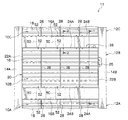
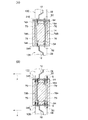
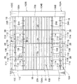
図1には、建物11を構成する架構12A、12B、12Cが示されており、架構12Aの上に架構12Bが構築され、更に架構12Bの上に架構12Cが構築されており、各架構12A、12B、12Cは上下方向に隣接している。これらの架構12A、12B、12Cは、左右の柱14A、14Bと上下の梁16A、16B(水平部材)とから構成されたラーメン構造とされている。柱14A、14B及び梁16A、16Bは、鉄筋コンクリート(以下、「RC」という)製とされている。   FIG. 1 shows frames 12A, 12B, and 12C constituting the building 11. The frame 12B is constructed on the frame 12A, and the frame 12C is further constructed on the frame 12B. , 12B, 12C are adjacent to each other in the vertical direction. These frames 12A, 12B, and 12C have a rigid frame structure that includes left and right columns 14A and 14B and upper and lower beams 16A and 16B (horizontal members). The columns 14A and 14B and the beams 16A and 16B are made of reinforced concrete (hereinafter referred to as “RC”).

各架構12A、12B、12Cには、鋼製耐震壁10A、10B、10Cが設置されている。これらの鋼製耐震壁10A、10B、10Cは同じ構成であるため、以下、鋼製耐震壁10Bについて詳説する。   Steel aseismic walls 10A, 10B, and 10C are installed on the frames 12A, 12B, and 12C, respectively. Since these steel earthquake-resistant walls 10A, 10B, and 10C have the same configuration, the steel earthquake-resistant wall 10B will be described in detail below.

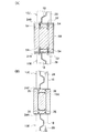
図1及び図2に示されるように、鋼製耐震壁10Bは、波形鋼板18及び枠体20を備えている。波形鋼板18は、鋼板を波形形状に折り曲げて形成されており、その折り筋を横(折り筋の向きを横方向)にして架構12Bの構面に配置されている。波形鋼板18の材料としては、普通鋼(例えば、SM490、SS400等)や低降伏点鋼(例えば、LY225等)等が用いられる。   As shown in FIGS. 1 and 2, the steel earthquake resistant wall 10 </ b> B includes a corrugated steel plate 18 and a frame 20. The corrugated steel plate 18 is formed by bending a steel plate into a corrugated shape, and the corrugated steel plate 18 is arranged on the construction surface of the frame 12B with the crease being horizontal (the direction of the crease is horizontal). As the material of the corrugated steel plate 18, ordinary steel (for example, SM490, SS400, etc.), low yield point steel (for example, LY225, etc.) or the like is used.

波形鋼板18の左右の縦辺には、鋼製の縦フランジ22A、22Bそれぞれ設けられている。この縦フランジ22A、22Bは板状に形成されており、波形鋼板18の左右の縦辺に沿って溶接等で固定されている。また、波形鋼板18の上下の横辺には、鋼製の横フランジ24A、24B(端部フランジ)がそれぞれ設けられている。この横フランジ24A、24Bは板状に形成されており、波形鋼板18の上下の横辺に沿って溶接等で固定されている。これらの縦フランジ22A、22B及び横フランジ24A、24Bの端部同士は溶接等で接合されている。これにより、波形鋼板18の外周部を囲む枠体20が構成されている。   Steel vertical flanges 22 </ b> A and 22 </ b> B are respectively provided on the left and right vertical sides of the corrugated steel sheet 18. The vertical flanges 22A and 22B are formed in a plate shape, and are fixed along the left and right vertical sides of the corrugated steel plate 18 by welding or the like. Further, steel horizontal flanges 24A and 24B (end flanges) are provided on the upper and lower horizontal sides of the corrugated steel sheet 18, respectively. The lateral flanges 24A and 24B are formed in a plate shape, and are fixed by welding or the like along the upper and lower lateral sides of the corrugated steel plate 18. The ends of the vertical flanges 22A and 22B and the horizontal flanges 24A and 24B are joined together by welding or the like. Thereby, the frame 20 surrounding the outer periphery of the corrugated steel plate 18 is configured.

また、縦フランジ22A、22B及び横フランジ24A、24Bには、せん断力伝達手段としてのスタッド26が突設されている。これらのスタッド26を柱14A、14B及び梁16A、16Bに埋設することにより、鋼製耐震壁10Bが架構12Bに取り付けられている。また、スタッド26を介して波形鋼板18と柱14A、14B及び梁16A、16Bとの間でせん断力が伝達可能となっている。   In addition, studs 26 serving as shearing force transmitting means project from the vertical flanges 22A and 22B and the horizontal flanges 24A and 24B. By embedding these studs 26 in the columns 14A and 14B and the beams 16A and 16B, the steel earthquake resistant wall 10B is attached to the frame 12B. Further, a shear force can be transmitted between the corrugated steel plate 18 and the columns 14A and 14B and the beams 16A and 16B via the stud 26.

なお、縦フランジ22A、22Bと柱14A、14B、及び横フランジ24A、24Bと梁16A、16Bとの接合方法は、上記したものに限らない。例えば、スタッドが立設された接合用プレートを柱14A、14B及び梁16A、16Bにそれぞれ埋設し、この接合用プレートに縦フランジ22A、22B及び横フランジ24A、24Bを溶接又はボルト等で接合しても良い。また、エポキシ樹脂等の接着剤により、縦フランジ22A、22Bと柱14A、14B、又は横フランジ24A、24Bと梁16A、16Bを接着接合しても良い(接着工法)。更に、縦フランジ22A、22B及び横フランジ24A、24Bは板状に限らず、H形鋼、L形鋼、T形鋼、チャネル鋼等でも良い。   In addition, the joining method of vertical flange 22A, 22B, pillar 14A, 14B, and horizontal flange 24A, 24B and beam 16A, 16B is not restricted above. For example, a connecting plate with studs erected is embedded in columns 14A and 14B and beams 16A and 16B, and vertical flanges 22A and 22B and horizontal flanges 24A and 24B are connected to the connecting plates by welding or bolts. May be. Further, the vertical flanges 22A and 22B and the columns 14A and 14B or the horizontal flanges 24A and 24B and the beams 16A and 16B may be bonded and bonded with an adhesive such as an epoxy resin (adhesion method). Further, the vertical flanges 22A and 22B and the horizontal flanges 24A and 24B are not limited to a plate shape, and may be H-shaped steel, L-shaped steel, T-shaped steel, channel steel, or the like.

波形鋼板18の板面には、上下方向に延びる補剛リブ28が、水平方向(波形鋼板18の折り筋方向)に所定の間隔を空けて複数(図1では、3つ)設けられている。各補剛リブ28は鋼材で板状に形成されており、長手方向を上下方向として波形鋼板18に溶接等で接合されている。補剛リブ28の長手方向両端部は、横フランジ24A、24Bにそれぞれ溶接等で接合されている。   A plurality of (three in FIG. 1) stiffening ribs 28 extending in the vertical direction are provided on the plate surface of the corrugated steel plate 18 at predetermined intervals in the horizontal direction (folding direction of the corrugated steel plate 18). . Each stiffening rib 28 is formed of a steel material in a plate shape, and is joined to the corrugated steel plate 18 by welding or the like with the longitudinal direction as the vertical direction. Both ends in the longitudinal direction of the stiffening rib 28 are joined to the lateral flanges 24A and 24B by welding or the like.

図2に示されるように、補剛リブ28の幅Gは波形鋼板18の波の高さHより広くされており、波形鋼板18の面外方向両側へ突出している。この補剛リブ28によって、波形鋼板18に面外剛性(面外方向(矢印A方向)の変形に対する剛性)が付与され、波形鋼板18のせん断変形量、せん断力が所定値(設計値)に達する前に、当該波形鋼板18がせん断座屈しないようになっている。この補剛リブ28によって波形鋼板18に付与される面外剛性は、補剛リブ28の材料強度、板厚、幅、断面2次モーメント(曲げ剛性)、補剛リブ28の端部の固定度、補剛リブ28の設置数を変えることにより適宜設計される。   As shown in FIG. 2, the width G of the stiffening rib 28 is wider than the wave height H of the corrugated steel plate 18 and protrudes to both sides in the out-of-plane direction of the corrugated steel plate 18. By this stiffening rib 28, out-of-plane rigidity (stiffness against deformation in the out-of-plane direction (arrow A direction)) is imparted to the corrugated steel sheet 18, and the shear deformation amount and shear force of the corrugated steel sheet 18 become predetermined values (design values). Before reaching, the corrugated steel sheet 18 is prevented from shear buckling. The out-of-plane rigidity imparted to the corrugated steel plate 18 by the stiffening ribs 28 is the material strength, plate thickness, width, cross-sectional secondary moment (bending rigidity) of the stiffening ribs 28, and the degree of fixation of the end portions of the stiffening ribs 28. It is designed as appropriate by changing the number of the stiffening ribs 28 installed.

なお、補剛リブ28と波形鋼板18との接合は、幅方向一端が波形形状の補剛リブ28を波形鋼板18の板面に嵌め合わせ、当該補剛リブ28を波形鋼板18の板面に溶接しても良いし、波形鋼板18を水平方向に複数のピースに分割し、ピース間に配置された補剛リブ28と各ピースの端部とを溶接等で接合しても良い。   The stiffening rib 28 and the corrugated steel plate 18 are joined by fitting the stiffening rib 28 having a corrugated shape at one end in the width direction to the plate surface of the corrugated steel plate 18. The corrugated steel plate 18 may be divided into a plurality of pieces in the horizontal direction, and the stiffening ribs 28 arranged between the pieces and the end portions of the pieces may be joined by welding or the like.

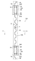
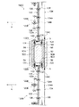
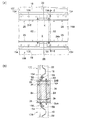
図1及び図3に示されるように、梁16A、16Bには、中空部材50(伝達手段)が埋設されている。中空部材50は角形鋼管からなり、上下の梁16A、16Bの材軸方向に沿って複数(図1では、各梁16A、16Bに3つ)埋設されている。中空部材50は、各鋼製耐震壁10A、10B、10Cの補剛リブ28の間(鋼製耐震壁10Aの補剛リブ28と鋼製耐震壁10Bの補剛リブ28の間、及び鋼製耐震壁10Bの補剛リブ28と鋼製耐震壁10Cの補剛リブ28の間)に配置されている。また、各中空部材50は、ボルト52及びナット54によって横フランジ24A、24Bと接合されている。   As shown in FIGS. 1 and 3, hollow members 50 (transmission means) are embedded in the beams 16A and 16B. The hollow member 50 is formed of a square steel pipe, and a plurality (three in each of the beams 16A and 16B in FIG. 1) are embedded along the material axis direction of the upper and lower beams 16A and 16B. The hollow member 50 is formed between the stiffening ribs 28 of the steel earthquake resistant walls 10A, 10B, and 10C (between the reinforcing ribs 28 of the steel earthquake resistant wall 10A and the reinforcing ribs 28 of the steel earthquake resistant wall 10B, and made of steel. (Between the stiffening rib 28 of the seismic wall 10B and the stiffening rib 28 of the steel seismic wall 10C). Each hollow member 50 is joined to the lateral flanges 24 </ b> A and 24 </ b> B by bolts 52 and nuts 54.

ここで、上の梁16Aに埋設された中空部材50について詳説する。なお、下の梁16Bに埋設された中空部材50は、上の梁16Aに埋設された中空部材50と同じ構成であるため説明を省略する。   Here, the hollow member 50 embedded in the upper beam 16A will be described in detail. Note that the hollow member 50 embedded in the lower beam 16B has the same configuration as the hollow member 50 embedded in the upper beam 16A, and thus the description thereof is omitted.

図3に示されるように、中空部材50と補剛リブ28とは、中空部材50の側壁50B、50Cが補剛リブ28の幅方向端部28Eにそれぞれ位置するように配置されている。即ち、引張り力S又は圧縮力T(図5(A)参照)が最大となる補剛リブ28の幅方向端部28Eが、上下の梁16A、16Bに埋設された中空部材50の側壁50B、50Cの間に配置されている。   As shown in FIG. 3, the hollow member 50 and the stiffening rib 28 are arranged such that the side walls 50 </ b> B and 50 </ b> C of the hollow member 50 are positioned at the width direction end portion 28 </ b> E of the stiffening rib 28. That is, the side wall 50B of the hollow member 50 in which the width direction end portion 28E of the stiffening rib 28 having the maximum tensile force S or compressive force T (see FIG. 5A) is embedded in the upper and lower beams 16A, 16B, It is arranged between 50C.

中空部材50の上下の底壁50Aは、梁16Aの上面及び下面から露出しており、鋼製耐震壁10Bの横フランジ24A、鋼製耐震壁10Cの横フランジ24Bにそれぞれ接触している。上下の底壁50Aと横フランジ24A、24Bとは、それぞれボルト52及びナット54によって接合されている。これにより、鋼製耐震壁10Bの補剛リブ28と鋼製耐震壁10Cの補剛リブ28との間で曲げモーメントが伝達可能となっている。なお、ナット54は、当該ナット54内にコンクリートが入り込まないように底付きナットとされており、中空部材50の内側から底壁50Aに溶接等で予め固定されている。この底付きナットとしては、袋ナットに鉄製、プラスチック製、セメント製などの蓋をしたものを利用すれば良い。また、中空部材50の底壁50Aを、鋼製耐震壁10Bの横フランジ24Aに予め溶接しておき、鋼製耐震壁10Bと同時に建て方を行い、それから上の梁16Aのコンクリートを打設しても良い。   The upper and lower bottom walls 50A of the hollow member 50 are exposed from the upper and lower surfaces of the beam 16A, and are in contact with the lateral flange 24A of the steel seismic wall 10B and the lateral flange 24B of the steel seismic wall 10C, respectively. The upper and lower bottom walls 50A and the lateral flanges 24A and 24B are joined by bolts 52 and nuts 54, respectively. Thereby, a bending moment can be transmitted between the stiffening rib 28 of the steel earthquake resistant wall 10B and the stiffening rib 28 of the steel earthquake resistant wall 10C. The nut 54 is a bottomed nut so that concrete does not enter the nut 54 and is fixed in advance to the bottom wall 50A from the inside of the hollow member 50 by welding or the like. As the bottomed nut, a cap nut having a lid made of iron, plastic, cement, or the like may be used. Further, the bottom wall 50A of the hollow member 50 is welded in advance to the lateral flange 24A of the steel seismic wall 10B, and the building is performed at the same time as the steel seismic wall 10B, and then the concrete of the upper beam 16A is placed. May be.

中空部材50の側壁50B、50Cには開口56が形成されており、この開口56及び中空部材50の材軸方向両端部から中空部材50内にコンクリートが充填可能となっている。中空部材50の内部には、梁鉄筋34と当該梁鉄筋34を補強するせん断補強筋36が配置されている。   Openings 56 are formed in the side walls 50 </ b> B and 50 </ b> C of the hollow member 50, and concrete can be filled into the hollow member 50 from both ends of the openings 56 and the hollow member 50 in the material axis direction. Inside the hollow member 50, a beam reinforcing bar 34 and a shear reinforcing bar 36 that reinforces the beam reinforcing bar 34 are arranged.

ここで、中空部材50は、内部に梁鉄筋34及びせん断補強筋36が配置された状態で梁16Aの型枠内に配置される。そして、型枠内に打設されたコンクリートが中空部材50内に充填される。このコンクリートが硬化することにより、中空部材50と梁16Aとが一体化される。   Here, the hollow member 50 is disposed in the form of the beam 16A with the beam reinforcing bar 34 and the shear reinforcing bar 36 disposed therein. Then, the concrete placed in the mold is filled into the hollow member 50. As the concrete hardens, the hollow member 50 and the beam 16A are integrated.

次に、第1実施形態の作用について説明する。   Next, the operation of the first embodiment will be described.

図4には、地震時等における架構12A、12B、12C及び鋼製耐震壁10A、10B、10Cの変形状態が示されている。なお、図4では、理解を容易にするために、架構12A、12B、12C及び鋼製耐震壁10A、10B、10Cの変形状態を誇張して示している。なお、鋼製耐震壁10A、10B、10Cの作用は同じであるため、鋼製耐震壁10Bの作用を中心に説明し、鋼製耐震壁10A、10Cの作用は適宜省略して説明する。   FIG. 4 shows the deformation state of the frames 12A, 12B, 12C and the steel earthquake resistant walls 10A, 10B, 10C at the time of an earthquake or the like. In FIG. 4, for easy understanding, the deformation state of the frames 12A, 12B, and 12C and the steel earthquake-resistant walls 10A, 10B, and 10C is exaggerated. In addition, since the effect | action of steel earthquake-resistant wall 10A, 10B, 10C is the same, it demonstrates centering on the effect | action of steel earthquake-resistant wall 10B, and omits suitably the effect | action of steel earthquake-resistant wall 10A, 10C.

図4に示されるように、風や地震等によって架構12Bに外力が作用すると、架構12Bに取り付けられた鋼製耐震壁10Bにせん断力が伝達され、波形鋼板18がせん断変形する。これにより、波形鋼板18が外力に抵抗して耐震性能を発揮する。また、外力に対して波形鋼板18が降伏するように設計することで、鋼材の履歴エネルギーによって振動エネルギーが吸収され、制振性能を発揮する。   As shown in FIG. 4, when an external force is applied to the frame 12B due to wind, earthquake, or the like, a shear force is transmitted to the steel seismic wall 10B attached to the frame 12B, and the corrugated steel sheet 18 undergoes shear deformation. Thereby, the corrugated steel plate 18 resists external force and exhibits seismic performance. In addition, by designing the corrugated steel plate 18 to yield with respect to external force, vibration energy is absorbed by the hysteresis energy of the steel material, and the damping performance is exhibited.

ここで、波形鋼板18のせん断変形が進むと、波形鋼板18が面外方向(図2の矢印A方向)へはらみ出してせん断座屈する恐れがある。そのため、波形鋼板18には補剛リブ28が設けられており、当該波形鋼板18のせん断変形量、せん断力が所定値(設計値)に達する前にせん断座屈しないようになっている。即ち、補剛リブ28によって波形鋼板18に面外剛性を付与することにより、鋼製耐震壁10Bのせん断座屈耐力を大きくしている。   Here, when the shear deformation of the corrugated steel sheet 18 proceeds, the corrugated steel sheet 18 may protrude in the out-of-plane direction (the direction of arrow A in FIG. 2) and be shear buckled. For this reason, the corrugated steel sheet 18 is provided with stiffening ribs 28 so that the shear deformation amount and shear force of the corrugated steel sheet 18 do not undergo shear buckling before reaching a predetermined value (design value). That is, by giving out-of-plane rigidity to the corrugated steel plate 18 by the stiffening ribs 28, the shear buckling strength of the steel earthquake resistant wall 10B is increased.

波形鋼板18に対する補剛リブ28の補剛効果は、補剛リブ28の材料強度、板厚、幅、断面2次モーメント(曲げ剛性)、補剛リブ28の端部の固定度、補剛リブ28の設置数等を増加することにより、向上させることができる。しかしながら、補剛リブの板厚、幅を増加したり、補剛リブ28の設置数を増加したりすると、補剛リブ28の材料コストが増加してしまう場合がある。また、波形鋼板18と補剛リブ28との接合は、一般的に溶接によって行われるところ、この溶接作業には熟練を要すると共に手間がかかる場合がある。   The stiffening effect of the stiffening rib 28 on the corrugated steel plate 18 includes the material strength, plate thickness, width, cross-sectional secondary moment (bending rigidity) of the stiffening rib 28, the degree of fixing of the end of the stiffening rib 28, It can be improved by increasing the number of 28 installed. However, when the plate thickness and width of the stiffening ribs are increased or the number of the stiffening ribs 28 is increased, the material cost of the stiffening ribs 28 may increase. Further, joining of the corrugated steel plate 18 and the stiffening ribs 28 is generally performed by welding. However, this welding work may require skill and labor.

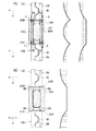
そこで、本実施形態では、補剛リブ28の端部の固定度を増強することにより、補剛リブ28の補剛効果を向上させている。具体的には、上下方向に隣接する各鋼製耐震壁10A、10B、10Cの補剛リブ28が、梁16A、16Bに埋設された中空部材50によって連結されている。これにより、鋼製耐震壁10Bの上部では、図5(A)に示されるように、鋼製耐震壁10B、10Cの波形鋼板18がそれぞれ面外方向(矢印A方向)へ変形したときに、中空部材50の側壁50Bに引張り力Sが作用すると共に、中空部材50の側壁50Cに圧縮力Tが作用し、鋼製耐震壁10Aの補剛リブ28と鋼製耐震壁10Bの補剛リブ28との間で曲げモーメントが伝達される。これにより、鋼製耐震壁10Bの補剛リブ28の上端部と、鋼製耐震壁10Aの補剛リブ28の下端部の回転(回転変形)が抑制され、これらの固定度が上がる。なお、梁16Aに発生する曲げモーメントは、鋼製耐震壁10Bの横フランジ24Aと鋼製耐震壁10Cの横フランジ24Bの間に距離、即ち、鋼製耐震壁10B、10Cの支点間距離によって変化する。従って、図5(A)には、想定される2つの曲げモーメント図を例示している。   Therefore, in the present embodiment, the stiffening effect of the stiffening rib 28 is improved by increasing the fixing degree of the end of the stiffening rib 28. Specifically, the stiffening ribs 28 of the steel earthquake-resistant walls 10A, 10B, and 10C adjacent in the vertical direction are connected by the hollow member 50 embedded in the beams 16A and 16B. Thereby, in the upper part of the steel earthquake-resistant wall 10B, as shown in FIG. 5A, when the corrugated steel plates 18 of the steel earthquake-resistant walls 10B and 10C are respectively deformed in the out-of-plane direction (arrow A direction), A tensile force S acts on the side wall 50B of the hollow member 50, and a compressive force T acts on the side wall 50C of the hollow member 50, and the stiffening rib 28 of the steel seismic wall 10A and the stiffening rib 28 of the steel seismic wall 10B. Bending moment is transmitted between them. Thereby, rotation (rotational deformation) of the upper end part of the stiffening rib 28 of the steel seismic wall 10B and the lower end part of the stiffening rib 28 of the steel seismic wall 10A is suppressed, and the degree of fixation thereof is increased. The bending moment generated in the beam 16A varies depending on the distance between the horizontal flange 24A of the steel earthquake resistant wall 10B and the horizontal flange 24B of the steel earthquake resistant wall 10C, that is, the distance between the fulcrums of the steel earthquake resistant walls 10B and 10C. To do. Therefore, FIG. 5A illustrates two possible bending moment diagrams.

これに対して、図5(B)に示される比較例のように、鋼製耐震壁10B、10Cの横フランジ24A、24Bと梁16Aとをスタッド38で接合した場合、図中の二点鎖線で示すように、横フランジ24A、24Bが回転する恐れがあり、横フランジ24A、24Bに接合された補剛リブ28の固定度が低下する。そのため、図5(B)に示す比較例では、鋼製耐震壁10Bの補剛リブ28の上端部と梁16Aとは、構造設計上ピン接合(回転自由)として取り扱われるのが一般的である。同様に、鋼製耐震壁10Cの補剛リブ28の下端部についても、構造計算上ピン接合として取り扱われる。   On the other hand, when the lateral flanges 24A and 24B of the steel earthquake resistant walls 10B and 10C and the beam 16A are joined by the stud 38 as in the comparative example shown in FIG. 5B, the two-dot chain line in the figure. As shown, the lateral flanges 24A and 24B may rotate, and the fixing degree of the stiffening ribs 28 joined to the lateral flanges 24A and 24B decreases. Therefore, in the comparative example shown in FIG. 5B, the upper end portion of the stiffening rib 28 of the steel seismic wall 10B and the beam 16A are generally handled as pin joints (rotation free) in terms of structural design. . Similarly, the lower end portion of the stiffening rib 28 of the steel earthquake resistant wall 10C is also handled as a pin joint for structural calculation.

一方、本実施形態のように、中空部材50によって鋼製耐震壁10Bの補剛リブ28と鋼製耐震壁10Cの補剛リブ28との間で曲げモーメントを伝達することにより、鋼製耐震壁10Bの補剛リブ28の上端部、及び鋼製耐震壁10Cの補剛リブ28の下端部の回転が抑制され、固定度が上がる。従って、補剛リブ28によって波形鋼板18に付与される面外剛性が大きくなり、架構12B、12Cに取り付けられた鋼製耐震壁10B、10Cのせん断座屈耐力が大きくなる。よって、補剛リブ28の板厚、幅、設置数等を抑えつつ、鋼製耐震壁10B、10Cのせん断座屈耐力を大きくすることができ、鋼製耐震壁10B、10Cの耐震性能、制振性能を向上させることができる。特に、本実施形態は、階高が高い建物等において、鋼製耐震壁10B、10Cの高さが高くなり、必要となる補剛リブ28が長くなる場合に効果的である。なお、図示を省略するが、鋼製耐震壁10Bの下部でも、鋼製耐震壁10Bの補剛リブ28と鋼製耐震壁10Aの補剛リブ28との間で曲げモーメントが伝達されるため、鋼製耐震壁10A、10Bの耐震性能、制振性能が向上する。
On the other hand, by transmitting a bending moment between the stiffening rib 28 of the steel earthquake resistant wall 10B and the reinforcing rib 28 of the steel earthquake resistant wall 10C by the hollow member 50 as in this embodiment, the steel earthquake resistant wall is transmitted. The rotation of the upper end portion of the 10B stiffening rib 28 and the lower end portion of the stiffening rib 28 of the steel seismic wall 10C is suppressed, and the fixing degree is increased. Therefore, the out-of-plane rigidity imparted to the corrugated steel plate 18 by the stiffening ribs 28 increases, and the shear buckling strength of the steel seismic walls 10B and 10C attached to the frames 12B and 12C increases. Therefore, it is possible to increase the shear buckling strength of the steel earthquake resistant walls 10B and 10C while suppressing the plate thickness, width, number of installations, and the like of the stiffening ribs 28, and the seismic performance and control of the steel earthquake resistant walls 10B and 10C. Vibration performance can be improved. In particular, this embodiment is effective when the height of the steel seismic walls 10B and 10C is high and the required stiffening ribs 28 are long in a building or the like having a high floor height. Although illustration is omitted, since a bending moment is transmitted between the stiffening rib 28 of the steel seismic wall 10B and the stiffening rib 28 of the steel seismic wall 10A even at the lower part of the steel seismic wall 10B. The seismic performance and damping performance of the steel seismic walls 10A and 10B are improved.

次に、本実施形態に係る曲げモーメントの伝達機構を梁に置き換えて説明する。図6(A)〜図6(C)には、鉛直荷重(長期荷重)を受ける梁58A、58B、及びその曲げモーメント図が示されている。これらの梁58A、58Bはその端部(支点P1〜P4)でピン支持されている。   Next, the bending moment transmission mechanism according to this embodiment will be described by replacing it with a beam. 6A to 6C show beams 58A and 58B that receive a vertical load (long-term load) and bending moment diagrams thereof. These beams 58A and 58B are pin-supported at their ends (fulcrum points P1 to P4).

図6(A)に示す構成では、梁58Aと梁58Bとが連続しておらず、曲げモーメントが連続していない。図6(B)に示す構成では、梁58Aと梁58Bが連続しているため、梁58A、58Bの端部(支点P2、P3)の固定度が上がり、曲げモーメントが連続している。図6(C)に示す構成では、梁58Aの支点P2と梁58Bの支点P3との間に設けられた部材を介して梁58Aと梁58Bとが連続しているため、図6(B)と同様に、梁58A、58Bの端部(支点P2、P3)の固定度が上がり、曲げモーメントが連続している。即ち、図6(A)の梁58A、58Bと比較して、図6(B)及び図6(C)に示される梁58A、58Bは、同じ荷重に対して変形が小さく、剛性が向上している。   In the configuration shown in FIG. 6A, the beam 58A and the beam 58B are not continuous, and the bending moment is not continuous. In the configuration shown in FIG. 6B, since the beam 58A and the beam 58B are continuous, the fixing degree of the ends (fulcrum points P2 and P3) of the beams 58A and 58B is increased, and the bending moment is continuous. In the configuration shown in FIG. 6C, the beam 58A and the beam 58B are continuous through a member provided between the fulcrum P2 of the beam 58A and the fulcrum P3 of the beam 58B. Similarly to the above, the fixing degree of the ends (fulcrum points P2 and P3) of the beams 58A and 58B is increased, and the bending moment is continuous. That is, compared to the beams 58A and 58B in FIG. 6A, the beams 58A and 58B shown in FIG. 6B and FIG. ing.

ここで、本実施形態は、図6(B)又は図6(C)の応力状態に近い状態を実現するものであり、鋼製耐震壁10のせん断変形が進捗してせん断座屈しようとしたときに、その面外力に対する剛性を向上しようとするものである。図6(C)では、支点P2と支点P3の間に曲げモーメントを伝達、連続させる部材が必要であるが、この部材に相当するのが本実施形態の伝達手段(中空部材50)であり、支点P2、P3は梁や床スラブに相当する。
なお、支点P2と支点P3の間のモーメント状態は、荷重や支点P2、P3の間の距離によって変化するため、ここで示すモーメントは一例である。
Here, the present embodiment realizes a state close to the stress state of FIG. 6B or FIG. 6C, and the shear deformation of the steel seismic wall 10 has progressed to attempt to buckle shear. Sometimes, it tries to improve the rigidity against the out-of-plane force. In FIG. 6 (C), a member that transmits and continues the bending moment between the fulcrum P2 and the fulcrum P3 is necessary. The transmission means (hollow member 50) of the present embodiment corresponds to this member. The fulcrums P2 and P3 correspond to beams and floor slabs.
In addition, since the moment state between the fulcrum P2 and the fulcrum P3 changes with the load and the distance between the fulcrums P2 and P3, the moment shown here is an example.

また、本実施形態では、中空部材50の側壁50B、50Cに開口56が形成されているため、中空部材50内へのコンクリートが充填し易くなっている。従って、梁16Aと中空部材50との一体性が向上すると共に、梁16Aの施工性が向上する。   Moreover, in this embodiment, since the opening 56 is formed in the side walls 50B and 50C of the hollow member 50, it is easy to fill the hollow member 50 with concrete. Therefore, the integrity of the beam 16A and the hollow member 50 is improved, and the workability of the beam 16A is improved.

ここで、補剛リブ28から中空部材50に曲げモーメントが伝達されると、中空部材50にねじりモーメントが発生し、中空部材50が当該中空部材50の材軸方向を回転軸として回転しようとする。中空部材50が回転すると、補剛リブ28の上端部及び下端部の固定度が下がるため、中空部材50に発生するねじりモーメントを周辺の部材(例えば、柱、スラブなど)に伝達し、当該中空部材50の回転を抑制することが望ましい。中空部材50の回転を抑制することで、補剛リブ28の拘束力が増加し、補剛リブ28の補剛効果を更に高めることができるためである。   Here, when a bending moment is transmitted from the stiffening rib 28 to the hollow member 50, a torsional moment is generated in the hollow member 50, and the hollow member 50 attempts to rotate with the material axis direction of the hollow member 50 as the rotation axis. . When the hollow member 50 rotates, the upper end portion and the lower end portion of the stiffening rib 28 are fixed. As a result, the torsional moment generated in the hollow member 50 is transmitted to surrounding members (for example, columns, slabs, etc.) It is desirable to suppress the rotation of the member 50. This is because the restraining force of the stiffening rib 28 is increased by suppressing the rotation of the hollow member 50, and the stiffening effect of the stiffening rib 28 can be further enhanced.

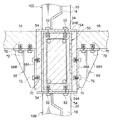
例えば、図7に示す構成では、梁16A内には、当該梁16Aより僅かに長い部材長さを有する中空部材62が埋設されており、中空部材62の材軸方向の端部62Aが梁16Aと柱14A、14Bとの仕口部64(図7における斜線部)にそれぞれ達している。このため、中空部材62に発生するねじりモーメントが、高剛性とされた仕口部64に伝達され、そのねじりモーメントに柱14A、14B等が抵抗することによって、中空部材62の回転が抑制される。従って、中空部材62に連結された補剛リブ28の上端部及び下端部の回転が抑制されるため、補剛リブ28の補剛効果を高めることができる。   For example, in the configuration shown in FIG. 7, a hollow member 62 having a member length slightly longer than the beam 16A is embedded in the beam 16A, and an end 62A in the material axis direction of the hollow member 62 is formed in the beam 16A. And the pillars 14A and 14B reach the joint 64 (shaded area in FIG. 7). For this reason, the torsional moment generated in the hollow member 62 is transmitted to the joint portion 64 having high rigidity, and the columns 14A, 14B and the like resist the torsional moment, thereby suppressing the rotation of the hollow member 62. . Therefore, rotation of the upper end portion and the lower end portion of the stiffening rib 28 connected to the hollow member 62 is suppressed, so that the stiffening effect of the stiffening rib 28 can be enhanced.

なお、中空部材62の端部62Aが仕口部64に達するとは、中空部材62の端部62Aが仕口部64内にある場合だけでなく、当該端部62Aが仕口部64になくても、端部62Aが仕口部64付近にあれば良い。   Note that the end portion 62A of the hollow member 62 reaches the joint portion 64 not only when the end portion 62A of the hollow member 62 is in the joint portion 64 but also when the end portion 62A is not in the joint portion 64. However, the end 62A only needs to be near the joint portion 64.

また、図8に示す構成では、梁16Aに床スラブ66が支持されており、梁16Aと床スラブ66とが連結部材68によって連結されている。連結部材68は、梁16Aの両側に配置されており、梁16Aと床スラブ66とにまたがって配置されるL型のアングル68Aと、当該アングル68Aを補強するリブ68Bとから構成されている。このアングル68Aは、ボルト72及びアンカーナット70によって梁16Aの側面及び床スラブ66の下面に固定されている。この連結部材68によって、梁16Aと床スラブ66とを連結することにより、梁16Aの回転(梁16Aの材軸方向を回転軸とした回転)が抑制される。この結果、中空部材50の回転(中空部材50の材軸方向を回転軸とした回転)が抑制され、中空部材50のねじりモーメントが床スラブ66に伝達される。従って、中空部材50に連結された補剛リブ28の上端部及び下端部の固定度が上がり、補剛リブ28の補剛効果を高めることができる。   In the configuration shown in FIG. 8, the floor slab 66 is supported by the beam 16 </ b> A, and the beam 16 </ b> A and the floor slab 66 are connected by the connecting member 68. The connecting member 68 is disposed on both sides of the beam 16A, and includes an L-shaped angle 68A that is disposed across the beam 16A and the floor slab 66, and a rib 68B that reinforces the angle 68A. The angle 68A is fixed to the side surface of the beam 16A and the lower surface of the floor slab 66 by bolts 72 and anchor nuts 70. By connecting the beam 16A and the floor slab 66 by the connecting member 68, rotation of the beam 16A (rotation with the material axis direction of the beam 16A as a rotation axis) is suppressed. As a result, the rotation of the hollow member 50 (rotation with the material axis direction of the hollow member 50 as the rotation axis) is suppressed, and the torsional moment of the hollow member 50 is transmitted to the floor slab 66. Accordingly, the fixing degree of the upper end portion and the lower end portion of the stiffening rib 28 connected to the hollow member 50 is increased, and the stiffening effect of the stiffening rib 28 can be enhanced.

なお、図8では、アングル68Aを例に連結部材68を説明したが、連結部材としては、一般的なハンチや、梁16Aと床スラブ66との間に配置される斜材(ブレース)を用いることができる。また、床スラブ66のみで梁16Aに発生する曲げモーメントに抵抗できる場合は、連結部材68を当然省略できる。   In FIG. 8, the connecting member 68 has been described by taking the angle 68A as an example. However, as the connecting member, a general haunch or a diagonal member (brace) disposed between the beam 16A and the floor slab 66 is used. be able to. If the floor slab 66 alone can resist the bending moment generated in the beam 16A, the connecting member 68 can be omitted as a matter of course.

また、本実施形態では、伝達手段として中空部材50を用いたがこれに限定されない。例えば、図9(A)に示されるように、上下方向に対向する一対のフランジ74Aの間に、複数(図9(A)では、2枚)のウェブ74Bが設けられた形鋼部材74を梁16A内に埋設し、当該形鋼部材74のフランジ74Aと、鋼製耐震壁10B、10Cの横フランジ24A、24Bとを接合しても良い。なお、形鋼部材74のウェブ74Bには、形鋼部材74の内部へコンクリートを充填するための開口76が形成されている。   Moreover, in this embodiment, although the hollow member 50 was used as a transmission means, it is not limited to this. For example, as shown in FIG. 9A, a structural steel member 74 provided with a plurality of (two in FIG. 9A) webs 74B between a pair of flanges 74A facing in the vertical direction. It may be embedded in the beam 16A and the flange 74A of the shaped steel member 74 may be joined to the lateral flanges 24A and 24B of the steel earthquake resistant walls 10B and 10C. An opening 76 for filling the inside of the shape steel member 74 with concrete is formed in the web 74B of the shape steel member 74.

また、図9(B)に示されるように、一対のC形鋼(形鋼部材)78A、78Bを、補剛リブ28の幅方向端部に位置するように梁16A内に埋設し、各C形鋼78A、78Bと横フランジ24Aとを接合しても良い。この場合、補剛リブ28が波形鋼板18の面外方向(矢印A方向)へ変形したときに、C形鋼78Aに引張り力Sが作用し、C形鋼78Bに圧縮力Tが作用する。これにより、鋼製耐震壁10Bの補剛リブ28と鋼製耐震壁10Cの補剛リブ28との間で曲げモーメントが伝達される。なお、各C形鋼78A、78Bには、C形鋼78AとC形鋼78Bとの間にコンクリートを充填するための開口79が形成されている。   Further, as shown in FIG. 9B, a pair of C-shaped steel (section steel members) 78A, 78B is embedded in the beam 16A so as to be positioned at the end of the stiffening rib 28 in the width direction. The C-shaped steel 78A, 78B and the lateral flange 24A may be joined. In this case, when the stiffening rib 28 is deformed in the out-of-plane direction (arrow A direction) of the corrugated steel plate 18, the tensile force S acts on the C-shaped steel 78A, and the compressive force T acts on the C-shaped steel 78B. Thereby, a bending moment is transmitted between the stiffening rib 28 of the steel seismic wall 10B and the stiffening rib 28 of the steel seismic wall 10C. Each C-shaped steel 78A, 78B has an opening 79 for filling the concrete between the C-shaped steel 78A and the C-shaped steel 78B.

更に、図10、図11(A)、及び図11(B)に示されるように、梁16Aの一部をCFT(Concrete Filled Steel Tube)造としても良い。梁16Aは、表面が中空部材98(伝達手段)で覆われたCFT造の部位と、一般的なRC造の部位とから構成されている。角形鋼管からなる中空部材98は、鋼製耐震壁10B、10Cの横フランジ24A、24Bにそれぞれ接合され、鋼製耐震壁10Bの補剛リブ28と鋼製耐震壁10Cの補剛リブ28との間で曲げモーメントが伝達可能となっている。この中空部材98は型枠として使用することができるため、梁16Aの施工性が向上する。なお、梁16A全体をCFT造としても良い。   Furthermore, as shown in FIG. 10, FIG. 11 (A), and FIG. 11 (B), a part of the beam 16A may be made of CFT (Concrete Filled Steel Tube). The beam 16A is composed of a CFT site whose surface is covered with a hollow member 98 (transmission means) and a general RC site. The hollow member 98 made of a square steel pipe is joined to the lateral flanges 24A and 24B of the steel earthquake resistant walls 10B and 10C, respectively, and the stiffening rib 28 of the steel earthquake resistant wall 10B and the stiffening rib 28 of the steel earthquake resistant wall 10C. The bending moment can be transmitted between them. Since the hollow member 98 can be used as a mold, the workability of the beam 16A is improved. The entire beam 16A may be made of CFT.

次に、第2実施形態について説明する。なお、第1実施形態と同じ構成ものは同符号を付すると共に、適宜省略して説明する。   Next, a second embodiment will be described. Note that the same components as those in the first embodiment are denoted by the same reference numerals and will be appropriately omitted.

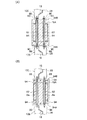
図12に示されるように、第2実施形態では、伝達手段としてPC鋼材82(棒鋼材)を用いている。図13に示されるように、梁16A内には、PC鋼材82が貫通される円筒形状のシース管84が上下方向を長手方向として埋設されている。このシース管84は、補剛リブ28の厚さ方向両側に位置すると共に(図12参照)、波形鋼板18の面外方向両側に位置しており(図13参照)、各シース管84内にPC鋼線、PC鋼棒等からなるPC鋼材82が配置されている。なお、説明を省略するが、前述したシース管84と同様のシース管が梁16Bにも埋設されている。   As shown in FIG. 12, in the second embodiment, a PC steel material 82 (bar steel material) is used as the transmission means. As shown in FIG. 13, a cylindrical sheath tube 84 through which the PC steel material 82 passes is embedded in the beam 16 </ b> A with the vertical direction as the longitudinal direction. The sheath tube 84 is located on both sides of the stiffening rib 28 in the thickness direction (see FIG. 12), and is located on both sides in the out-of-plane direction of the corrugated steel plate 18 (see FIG. 13). A PC steel material 82 made of a PC steel wire, a PC steel rod or the like is disposed. Although not described, a sheath tube similar to the sheath tube 84 described above is also embedded in the beam 16B.

鋼製耐震壁10Bの横フランジ24A及び鋼製耐震壁10Cの横フランジ24Bには、PC鋼材82が貫通する貫通孔がそれぞれ形成されている。PC鋼材82の材軸方向両端部にはネジ部が設けられており、当該ネジ部にナット88が取り付けられている。このナット88を締め付けて横フランジ24A、24Bにそれぞれ係止することにより、PC鋼材82が張力(プレストレス)を付与された状態で保持されている。このPC鋼材によって、鋼製耐震壁10Bの横フランジ24Aと鋼製耐震壁10Cの横フランジ24Bとが連結されると共に、梁16Aに鋼製耐震壁10Bの横フランジ24A及び鋼製耐震壁10Cの横フランジ24Bがそれぞれ圧着(圧着接合)されている。   Through holes through which the PC steel material 82 penetrates are formed in the lateral flange 24A of the steel earthquake resistant wall 10B and the lateral flange 24B of the steel earthquake resistant wall 10C. Screw portions are provided at both ends in the axial direction of the PC steel material 82, and nuts 88 are attached to the screw portions. By tightening the nut 88 and locking it to the lateral flanges 24A and 24B, the PC steel material 82 is held in a state where tension (prestress) is applied. With this PC steel material, the horizontal flange 24A of the steel earthquake-resistant wall 10B and the horizontal flange 24B of the steel earthquake-resistant wall 10C are connected, and the horizontal flange 24A of the steel earthquake-resistant wall 10B and the steel earthquake-resistant wall 10C are connected to the beam 16A. The lateral flanges 24B are crimped (crimped).

次に、第2実施形態の作用について説明する。   Next, the operation of the second embodiment will be described.

図13に示されるように、鋼製耐震壁10Bの横フランジ24Aと鋼製耐震壁10Cの横フランジ24BとをPC鋼材82で連結したことにより、鋼製耐震壁10B、10Cの補剛リブ28が面外方向(矢印A方向)へ変形したときに、一方のPC鋼材82に引張り力Sが作用すると共に、他方のPC鋼材82に圧縮力Tが作用し、鋼製耐震壁10Bの補剛リブ28と鋼製耐震壁10Cの補剛リブ28との間で曲げモーメントが伝達される。これにより、鋼製耐震壁10Bの補剛リブ28の上端部、及び鋼製耐震壁10Cの補剛リブ28の下端部の回転(回転変形)が抑制され、これらの上端部及び下端部の固定度が上がる。従って、補剛リブ28によって波形鋼板18に付与される面外剛性が大きくなり、架構12B、12Cに取り付けられた鋼製耐震壁10B、10Cのせん断座屈耐力が大きくなる。よって、補剛リブ28の板厚、幅、設置数等を抑えつつ、鋼製耐震壁10B、10Cのせん断座屈耐力を大きくすることができる。
なお、図示を省略するが、鋼製耐震壁10Bの下部においても、PC鋼材82を介して鋼製耐震壁10Bの補剛リブ28と鋼製耐震壁10Aの補剛リブ28との間で曲げモーメントが伝達される。
As shown in FIG. 13, by connecting the horizontal flange 24A of the steel earthquake-resistant wall 10B and the horizontal flange 24B of the steel earthquake-resistant wall 10C with a PC steel material 82, the stiffening ribs 28 of the steel earthquake-resistant walls 10B and 10C are connected. Is deformed in the out-of-plane direction (arrow A direction), a tensile force S acts on one PC steel material 82, and a compressive force T acts on the other PC steel material 82, thereby stiffening the steel earthquake resistant wall 10B. A bending moment is transmitted between the rib 28 and the stiffening rib 28 of the steel seismic wall 10C. Thereby, rotation (rotational deformation) of the upper end part of the stiffening rib 28 of the steel earthquake-resistant wall 10B and the lower end part of the stiffening rib 28 of the steel earthquake-resistant wall 10C is suppressed, and the upper end part and the lower end part are fixed. The degree goes up. Therefore, the out-of-plane rigidity imparted to the corrugated steel plate 18 by the stiffening ribs 28 increases, and the shear buckling strength of the steel seismic walls 10B and 10C attached to the frames 12B and 12C increases. Therefore, the shear buckling strength of the steel earthquake resistant walls 10B and 10C can be increased while suppressing the plate thickness, width, number of installations, and the like of the stiffening ribs 28.
In addition, although illustration is abbreviate | omitted, also in the lower part of the steel earthquake-resistant wall 10B, it bends between the stiffening rib 28 of the steel earthquake-resistant wall 10B and the reinforcing rib 28 of the steel earthquake-resistant wall 10A via the PC steel material 82. Moment is transmitted.

また、PC鋼材82に付与された張力がゼロになるまで、横フランジ24A、24Bと梁16Aとの接触状態が維持される。従って、PC鋼材82に張力を付与しない場合と比較して、横フランジ24A、24Bの回転が更に抑制され、補剛リブ28の補剛効果を高めることができる。   Further, the contact state between the lateral flanges 24A and 24B and the beam 16A is maintained until the tension applied to the PC steel material 82 becomes zero. Therefore, as compared with the case where no tension is applied to the PC steel material 82, the rotation of the lateral flanges 24A and 24B is further suppressed, and the stiffening effect of the stiffening ribs 28 can be enhanced.

更に、PC鋼材82によって横フランジ24A、24Bを梁16Aに圧着することにより、梁16Aと横フランジ24Aとの間に発生する摩擦力が大きくなる。従って、横フランジ24A、24Bと梁16Aとの間のせん断力の伝達効率が向上するため、鋼製耐震壁10Bの耐震性能、制振性能が向上する。   Further, by pressing the lateral flanges 24A and 24B to the beam 16A by the PC steel material 82, the frictional force generated between the beam 16A and the lateral flange 24A is increased. Therefore, since the transmission efficiency of the shearing force between the lateral flanges 24A, 24B and the beam 16A is improved, the seismic performance and damping performance of the steel seismic wall 10B are improved.

なお、本実施形態では、補剛リブ28の厚さ方向両側、及び波形鋼板18の面外方向両側にPC鋼材82を設けたが、これに限定されない。PC鋼材82は、必要に応じて適宜設ければ良く、少なくも一本のPC鋼材82があれば良い。また、シース管84内にグラウト、モルタル等の充填材を充填して、シース管84とPC鋼材82との一体性を高めても良いし、アフターボンド工法、アンボンド工法を用いても良い。   In the present embodiment, the PC steel materials 82 are provided on both sides in the thickness direction of the stiffening ribs 28 and on both sides in the out-of-plane direction of the corrugated steel plate 18, but the present invention is not limited to this. The PC steel material 82 may be appropriately provided as necessary, and at least one PC steel material 82 may be provided. In addition, the sheath tube 84 may be filled with a filler such as grout or mortar to enhance the integrity of the sheath tube 84 and the PC steel material 82, or an afterbond method or an unbond method may be used.

更に、シース管84を省略し、梁16A内にPC鋼材82を直接埋設しても良い。シース管84を省略する場合は、例えば、図14(A)及び図14(B)に示されるように、梁16Aの施工時に、梁鉄筋34、せん断補強筋36と共に、PC鋼材82を型枠内に設置する。この際、PC鋼材82の軸方向両端部が、梁16Aの上面及び下面から突出するように配置する。そして、型枠内に打設されたコンクリートが硬化した後に、梁16Aの上面に鋼製耐震壁10Cの横フランジ24Bを載置し、当該横フランジ24BにPC鋼材82を貫通させる。次に、PC鋼材82のネジ部にナット88を取り付け、当該ナット88を締め付けて横フランジ24Bに係止する。これにより、PC鋼材82に張力が付与されると共に、横フランジ24A、24Bが梁16Aに圧着される。なお、PC鋼材82に剥離剤を適宜塗布し、PC鋼材82とコンクリートとの付着を防止しても良い。   Further, the sheath tube 84 may be omitted, and the PC steel material 82 may be directly embedded in the beam 16A. When the sheath tube 84 is omitted, for example, as shown in FIGS. 14 (A) and 14 (B), the PC steel material 82 is formed together with the beam reinforcing bar 34 and the shear reinforcing bar 36 at the time of construction of the beam 16A. Install in. At this time, the both ends in the axial direction of the PC steel material 82 are arranged so as to protrude from the upper surface and the lower surface of the beam 16A. Then, after the concrete placed in the mold is cured, the horizontal flange 24B of the steel earthquake resistant wall 10C is placed on the upper surface of the beam 16A, and the PC steel material 82 is passed through the horizontal flange 24B. Next, a nut 88 is attached to the threaded portion of the PC steel material 82, and the nut 88 is tightened to be locked to the lateral flange 24B. As a result, tension is applied to the PC steel material 82, and the lateral flanges 24A and 24B are pressed against the beam 16A. Note that a release agent may be appropriately applied to the PC steel material 82 to prevent adhesion between the PC steel material 82 and the concrete.

また、横フランジ24Aとナット88との間、及び横フランジ24Bとナット88の間に弾性体を挟んでも良い。例えば、図15(A)に示す構成では、横フランジ24A及び横フランジ24Bとナット88との間に弾性体としての皿バネ90が設けられている。ここで、梁16Aにたわみ・断面収縮(クリープ変形など)が生じると、梁16Aから横フランジ24Aが離間し、梁16Aと横フランジ24A、24Bとの間に隙間ができる恐れがある。一方、図15(A)に示す構成では、皿バネ90の復元力によって梁16Aと横フランジ24A、24Bとの隙間が抑制され、PC鋼材82に付与された張力(導入軸力)の減少が抑制されるため、梁16Aと横フランジ24A、24Bとの接触状態が保持される。従って、梁16Aと横フランジ24A、24Bとの接触状態が長期的に維持され、即ち、補剛リブ28の補剛効果が長期化される。   Further, an elastic body may be sandwiched between the lateral flange 24A and the nut 88 and between the lateral flange 24B and the nut 88. For example, in the configuration shown in FIG. 15A, a disc spring 90 as an elastic body is provided between the lateral flange 24 </ b> A and the lateral flange 24 </ b> B and the nut 88. Here, if the beam 16A is bent or contracted (creep deformation or the like), the horizontal flange 24A may be separated from the beam 16A, and a gap may be formed between the beam 16A and the horizontal flanges 24A and 24B. On the other hand, in the configuration shown in FIG. 15A, the clearance between the beam 16A and the lateral flanges 24A and 24B is suppressed by the restoring force of the disc spring 90, and the tension (introduction axial force) applied to the PC steel material 82 is reduced. Therefore, the contact state between the beam 16A and the lateral flanges 24A and 24B is maintained. Therefore, the contact state between the beam 16A and the lateral flanges 24A and 24B is maintained for a long period, that is, the stiffening effect of the stiffening rib 28 is prolonged.

ここで、図16に示される一般的な皿バネのバネ特性92(荷重変形関係)から分かるように、皿バネは、変形量に対して復元力の変動が小さい領域Rを有している。従って、皿バネ90が領域Rで変形するように、当該皿バネ90に圧力(初期圧力)を付与することにより、PC鋼材82に付与された張力(軸力)の減少を効率的に抑制することができる。そのため、皿バネ90は、領域Rで使用することが望ましい。なお、領域Rから外れた領域で、皿バネ90を使用しても良いことは勿論である。   Here, as can be seen from the spring characteristic 92 (load deformation relation) of a general disc spring shown in FIG. 16, the disc spring has a region R in which the fluctuation of the restoring force is small with respect to the deformation amount. Therefore, by applying a pressure (initial pressure) to the disc spring 90 so that the disc spring 90 is deformed in the region R, a decrease in the tension (axial force) applied to the PC steel material 82 is efficiently suppressed. be able to. Therefore, it is desirable to use the disc spring 90 in the region R. Needless to say, the disc spring 90 may be used in a region outside the region R.

なお、弾性体としての皿バネ90に替えて、バネ座金、波形座金等を用いても良い。また、これらの弾性体は、横フランジ24A、24Bとナット88との間、及び横フランジ24Bとナット88との間の少なくも一方に挟まれていれば良い。   Note that a spring washer, a corrugated washer, or the like may be used instead of the disc spring 90 as an elastic body. Further, these elastic bodies may be sandwiched between at least one of the side flanges 24A and 24B and the nut 88 and between the side flange 24B and the nut 88.

ところで、PC鋼材82に付与された張力(軸力)が減少した場合、梁16Aと横フランジ24A、24Bとの間に発生する摩擦力が減少し、梁16Aと横フランジ24A、24Bとの間で伝達されるせん断力が減少してしまう。従って、図15(B)に示されるように、横フランジ24A、24Bにスタッド94等を適宜突設し、当該スタッド94を梁16A内に埋設することにより、梁16Aと横フランジ24Aとの間でせん断力を伝達しても良い。   By the way, when the tension (axial force) applied to the PC steel material 82 decreases, the frictional force generated between the beam 16A and the lateral flanges 24A and 24B decreases, and the space between the beam 16A and the lateral flanges 24A and 24B. The shearing force transmitted by will decrease. Accordingly, as shown in FIG. 15B, a stud 94 or the like is appropriately provided on the horizontal flanges 24A and 24B, and the stud 94 is embedded in the beam 16A, so that the gap between the beam 16A and the horizontal flange 24A is obtained. The shearing force may be transmitted with.

また、PC鋼材82の機能としては、補剛リブ28に発生する曲げモーメントを伝達する機能と、梁16A、16Bと鋼製耐震壁10Bとの間でせん断力を相互に伝達する機能が挙げられる。これらの2つの機能をPC鋼材82に担わせても良いし、PC鋼材82にはもっぱら曲げモーメントを伝達する機能を担わせ、PC鋼材82とは別に設けられたスタッド、接着剤、溶接、ボルト等にせん断力を伝達する機能を担わせても良い。   Moreover, as a function of PC steel material 82, the function which transmits the bending moment which generate | occur | produces in the stiffening rib 28, and the function which transmits a shearing force mutually between the beams 16A and 16B and the steel earthquake-resistant wall 10B are mentioned. . These two functions may be assigned to the PC steel material 82, or the PC steel material 82 is exclusively responsible for transmitting the bending moment, and studs, adhesives, welding, bolts provided separately from the PC steel material 82. A function of transmitting a shearing force may be provided.

なお、本実施形態では、PC鋼材82に張力(プレストレス)を付与したが、この張力は適宜省略可能である。また、棒鋼材としてのPC鋼材82に替えて、ネジ鉄筋、ボルト、スタッドボルト等を用いることができる。   In this embodiment, tension (prestress) is applied to the PC steel material 82, but this tension can be omitted as appropriate. Moreover, it replaces with the PC steel material 82 as a bar steel material, and a screw rebar, a bolt, a stud bolt, etc. can be used.

次に、第3実施形態について説明する。なお、第1、第2実施形態と同じ構成ものは同符号を付すると共に、適宜省略して説明する。   Next, a third embodiment will be described. The same components as those in the first and second embodiments are denoted by the same reference numerals and will be appropriately omitted.

図17及び図18に示されるように、第3実施形態では、鉄骨造の架構102A、102B、102Cに鋼製耐震壁10A、10B、10Cが取り付けられている。各架構102A、102B、102Cは、角形鋼管からなる左右の柱104A、104Bと、H形鋼からなる上下の梁106A、106Bによって構成された、ラーメン構造とされている。梁106A、106Bは、対向する一対のフランジ108と、これらのフランジ108を連結するウェブ110によって構成されている。   As shown in FIGS. 17 and 18, in the third embodiment, steel earthquake resistant walls 10A, 10B, and 10C are attached to steel frames 102A, 102B, and 102C. Each of the frames 102A, 102B, and 102C has a ramen structure including left and right columns 104A and 104B made of square steel pipes and upper and lower beams 106A and 106B made of H-shaped steel. The beams 106 </ b> A and 106 </ b> B are configured by a pair of opposing flanges 108 and a web 110 that connects these flanges 108.

上下の梁106A、106Bと鋼製耐震壁10Bとは高力ボルト112及びナット114によって摩擦接合されており、梁106A、106Bと波形鋼板18との間でせん断力が伝達可能となっている。   The upper and lower beams 106A and 106B and the steel seismic wall 10B are friction-joined by high-strength bolts 112 and nuts 114, so that shear force can be transmitted between the beams 106A and 106B and the corrugated steel plate 18.

梁106A、106Bには、伝達手段としての鋼製プレート116が設けられている。各鋼製プレート116は、対向するフランジ108の間に設けられており、各鋼製耐震壁10A、10B、10Cの補剛リブ28の間(鋼製耐震壁10Aの補剛リブ28と鋼製耐震壁10Bの補剛リブ28の間、及び鋼製耐震壁10Bの補剛リブ28と鋼製耐震壁10Cの補剛リブ28の間)に配置されている。なお、本実施形態では、鋼製プレート116は、各補剛リブ28と同一面内に設けられている。   The beams 106A and 106B are provided with a steel plate 116 as a transmission means. Each steel plate 116 is provided between the opposing flanges 108, and is between the stiffening ribs 28 of the steel earthquake resistant walls 10A, 10B, and 10C (the stiffening rib 28 of the steel earthquake resistant wall 10A and the steel Between the stiffening ribs 28 of the seismic wall 10B and between the stiffening ribs 28 of the steel seismic wall 10B and the stiffening ribs 28 of the steel seismic wall 10C). In the present embodiment, the steel plate 116 is provided in the same plane as each of the stiffening ribs 28.

鋼製プレート116は、各梁106A、106Bのフランジ108及びウェブ110にそれぞれ溶接等で接合されている。また、鋼製プレート116は、各梁106A、106Bのフランジ108間に打設されたコンクリート118内に埋設されており、このコンクリート118によって鋼製プレート116の面外方向の変形が抑制されている。更に、鋼製プレート116には、スタッド32が立設されており、当該スタッド32によって鋼製プレート116とコンクリート118との一体性が高められている。この鋼製プレート116を介して、鋼製耐震壁10Aの補剛リブ28と鋼製耐震壁10Bの補剛リブ28との間、及び鋼製耐震壁10Bと鋼製耐震壁10Cとの間で曲げモーメントが伝達可能になっている。   The steel plate 116 is joined to the flange 108 and the web 110 of each beam 106A, 106B by welding or the like. Further, the steel plate 116 is embedded in the concrete 118 placed between the flanges 108 of the beams 106A and 106B, and the deformation of the steel plate 116 in the out-of-plane direction is suppressed by the concrete 118. . Further, studs 32 are provided upright on the steel plate 116, and the integrity of the steel plate 116 and the concrete 118 is enhanced by the studs 32. Via the steel plate 116, between the stiffening rib 28 of the steel seismic wall 10A and the stiffening rib 28 of the steel seismic wall 10B, and between the steel seismic wall 10B and the steel seismic wall 10C. The bending moment can be transmitted.

なお、コンクリート118に替えて、モルタル、グラウト、接着剤等を使用することができる。更に、スタッド32に替えて異形鉄筋を用いても良いし、鋼製プレート116の表面に凹凸を付けて、鋼製プレート116とコンクリート118との一体性を高めても良い。なお、コンクリート118、スタッド32は適宜省略可能である。   Note that mortar, grout, adhesive, or the like can be used instead of the concrete 118. Further, a deformed reinforcing bar may be used instead of the stud 32, or the surface of the steel plate 116 may be provided with unevenness to enhance the integrity of the steel plate 116 and the concrete 118. The concrete 118 and the stud 32 can be omitted as appropriate.

次に、第3実施形態の作用について説明する。   Next, the operation of the third embodiment will be described.

図18に示されるように、梁106Aのフランジ108間には、鋼製プレート116が設けられている。これにより、鋼製耐震壁10B、10Cの波形鋼板18が面外方向(矢印A方向)へ変形したときに、鋼製プレート116の一方の幅方向端部に引張り力Sが作用すると共に、他方の幅方向端部に圧縮力Tが作用し、鋼製耐震壁10Bの補剛リブ28と鋼製耐震壁10Cの補剛リブ28との間で曲げモーメントが伝達される。これにより、鋼製耐震壁10Bの補剛リブ28の上端部、及び鋼製耐震壁10Cの補剛リブ28の下端部の回転(回転変形)が抑制され、これらの上端部及び下端部の固定度が上がる。従って、補剛リブ28によって波形鋼板18に付与される面外剛性が大きくなる。   As shown in FIG. 18, a steel plate 116 is provided between the flanges 108 of the beam 106A. Thereby, when the corrugated steel plate 18 of the steel shear walls 10B and 10C is deformed in the out-of-plane direction (arrow A direction), the tensile force S acts on one end in the width direction of the steel plate 116, and the other A compressive force T acts on the width direction end of the steel plate, and a bending moment is transmitted between the stiffening rib 28 of the steel earthquake-resistant wall 10B and the stiffening rib 28 of the steel earthquake-resistant wall 10C. Thereby, rotation (rotational deformation) of the upper end part of the stiffening rib 28 of the steel earthquake-resistant wall 10B and the lower end part of the stiffening rib 28 of the steel earthquake-resistant wall 10C is suppressed, and the upper end part and the lower end part are fixed. The degree goes up. Accordingly, the out-of-plane rigidity imparted to the corrugated steel sheet 18 by the stiffening rib 28 is increased.

なお、図示を省略するが、鋼製耐震壁10Bの下部においても、鋼製プレート116を介して、鋼製耐震壁10Bの補剛リブ28と鋼製耐震壁10Aの補剛リブ28との間で曲げモーメントが伝達される。   Although illustration is omitted, also in the lower part of the steel earthquake resistant wall 10B, between the stiffening rib 28 of the steel earthquake resistant wall 10B and the stiffening rib 28 of the steel earthquake resistant wall 10A via the steel plate 116. The bending moment is transmitted with.

また、本実施形態では、鋼製プレート116がコンクリート118内に埋設されているため、鋼製プレート116の面外剛性が大きくなっている。また、コンクリート118自体が横フランジ24A、24Bの回転に対して抵抗する。従って、補剛リブ28の上端部及び下端部の固定度が上がり、補剛リブ28の補剛効果が向上する。
なお、梁106Aの上に床スラブを構築する場合、前述したように梁106Aと床スラブとの間に連結部材68やハンチを設けて梁106Aの回転を抑制し、補剛リブ28の端部の固定度を上げることも可能である。
In this embodiment, since the steel plate 116 is embedded in the concrete 118, the out-of-plane rigidity of the steel plate 116 is increased. Further, the concrete 118 itself resists the rotation of the lateral flanges 24A and 24B. Therefore, the fixing degree of the upper end portion and the lower end portion of the stiffening rib 28 is increased, and the stiffening effect of the stiffening rib 28 is improved.
When the floor slab is constructed on the beam 106A, as described above, the connecting member 68 and the hunch are provided between the beam 106A and the floor slab to suppress the rotation of the beam 106A, and the end portion of the stiffening rib 28 is provided. It is also possible to increase the degree of fixation.

また、本実施形態では、伝達手段として平板状の鋼製プレート116を用いたが、鋼製プレート116に替えて、T形鋼、L型鋼、C形鋼等の形鋼部材や、角形鋼管、丸形鋼管等の中空鋼材を用いることができる。更に、図13に示したようなPC鋼材82で鋼製耐震壁10Bの横フランジ24Aと鋼製耐震壁10Cの横フランジ24Bとを連結しても良い。この際、PC鋼材に張力を付与し、横フランジ24A、24Bを梁106A、106Bのフランジ108に圧着しても良い。   Moreover, in this embodiment, although the flat steel plate 116 was used as a transmission means, it replaced with the steel plate 116, shaped steel members, such as T-shaped steel, L-shaped steel, and C-shaped steel, a square steel pipe, A hollow steel material such as a round steel pipe can be used. Furthermore, you may connect the horizontal flange 24A of the steel earthquake-resistant wall 10B and the horizontal flange 24B of the steel earthquake-resistant wall 10C with the PC steel material 82 as shown in FIG. At this time, tension may be applied to the PC steel material and the lateral flanges 24A and 24B may be crimped to the flanges 108 of the beams 106A and 106B.

次に、第4実施形態について説明する。なお、第1〜第3実施形態と同じ構成ものは同符号を付すると共に、適宜省略して説明する。   Next, a fourth embodiment will be described. Note that the same components as those in the first to third embodiments are denoted by the same reference numerals and will be appropriately omitted.

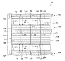
図19及び図20に示されるように、各架構12A、12B、12Cには、鋼製耐震壁120A、120B、120Cが配置されている。これらの鋼製耐震壁120A、120B、120Cは同じ構成であるため、以下、鋼製耐震壁120Bについて詳説する。   As shown in FIGS. 19 and 20, steel quake-resistant walls 120A, 120B, and 120C are arranged on the frames 12A, 12B, and 12C. Since these steel earthquake resistant walls 120A, 120B, and 120C have the same configuration, the steel earthquake resistant wall 120B will be described in detail below.

鋼製耐震壁120Bは、上下左右に配列された複数の形鋼部材122を備えている。図24に示されるように、各形鋼部材122はC形鋼からなり、ウェブ122A(鋼板)とウェブ122Aの長辺に設けられた一対のフランジ122Bと、を備えている。形鋼部材122としては、普通鋼(例えば、SM490、SS400等)や低降伏点鋼(例えば、LY225等)等が用いられる。   The steel seismic wall 120B includes a plurality of structural steel members 122 arranged vertically and horizontally. As shown in FIG. 24, each shape steel member 122 is made of C-shaped steel, and includes a web 122A (steel plate) and a pair of flanges 122B provided on the long sides of the web 122A. As the shape steel member 122, ordinary steel (for example, SM490, SS400, etc.), low yield point steel (for example, LY225, etc.), or the like is used.

図20に示されるように、上下方向に隣接する形鋼部材122は、各々のフランジ122Bを対向させて配置され、高力ボルト124及びナット126によって摩擦接合されており、これらのフランジ122Bの間でせん断力が伝達可能となっている。   As shown in FIG. 20, the structural steel members 122 adjacent in the vertical direction are arranged with their flanges 122B facing each other, and are frictionally joined by high-strength bolts 124 and nuts 126, and between these flanges 122B. Shear force can be transmitted.

水平方向に隣接する形鋼部材122は、連結部材134によって連結されている。連結部材134は、ウェブ134Aとフランジ134BとからなるT形鋼と、当該T形鋼の材軸方向両端部に接合された取付フランジ134C(端部フランジ)とを備え、材軸方向を上下方向として形鋼部材122の裏面側に配置されている。この連結部材134のフランジ134Bは、水平方向に隣接する形鋼部材122のウェブ122Aにまたがって配置されており、これらのウェブ122A及びフランジ134Bに貫通される高力ボルト136及びナット138によって摩擦接合されている。これにより、水平方向に隣接する形鋼部材122との間でせん断力が伝達可能となっている。   The structural steel members 122 adjacent in the horizontal direction are connected by a connecting member 134. The connecting member 134 includes a T-shaped steel made up of a web 134A and a flange 134B, and mounting flanges 134C (end flanges) joined to both ends of the T-shaped steel in the material axial direction. As shown in FIG. The flange 134B of the connecting member 134 is disposed across the web 122A of the structural member 122 adjacent in the horizontal direction, and is frictionally joined by a high-strength bolt 136 and a nut 138 that penetrate the web 122A and the flange 134B. Has been. Thereby, a shearing force can be transmitted between the structural steel members 122 adjacent in the horizontal direction.

連結部材134のウェブ134A(補剛リブ)は、当該連結部材134のフランジ134Bに沿って上下方向に延びると共に、フランジ134Bから形鋼部材122のウェブ122Aの面外方向へ突出している。このウェブ134Aによって、各形鋼部材122のウェブ122Aに面外剛性が付与されている。即ち、連結部材134のウェブ134Aは、各形鋼部材122のウェブ122Aのせん断座屈を防止する補剛リブとして機能する。   The web 134A (stiffening rib) of the connecting member 134 extends in the vertical direction along the flange 134B of the connecting member 134 and protrudes out of the plane of the web 122A of the structural steel member 122 from the flange 134B. Out-of-plane rigidity is imparted to the web 122A of each shape steel member 122 by the web 134A. That is, the web 134 </ b> A of the connecting member 134 functions as a stiffening rib that prevents shear buckling of the web 122 </ b> A of each shape steel member 122.

このように複数の形鋼部材122から構成された鋼製耐震壁120Bの左右の縦辺には、図19に示されるように、縦フランジ144A、144Bが設けられている。縦フランジ144A、144BはT形鋼からなり、当該縦フランジ144A、144Bに突設されたスタッド26を柱14A、14Bに埋設することにより、柱14A、14Bに固定されている。この縦フランジ144A、144Bには、形鋼部材122のウェブ122Aが重ね合わせられ、高力ボルト146及びナット(不図示)によって摩擦接合されている。これにより、左右の柱14A、14Bに鋼製耐震壁120Bが取り付けられると共に、左右の柱14A、14Bと鋼製耐震壁120Bとの間でせん断力が伝達可能となっている。   As shown in FIG. 19, vertical flanges 144 </ b> A and 144 </ b> B are provided on the left and right vertical sides of the steel earthquake resistant wall 120 </ b> B configured by the plurality of shaped steel members 122 as described above. The vertical flanges 144A and 144B are made of T-shaped steel, and the studs 26 protruding from the vertical flanges 144A and 144B are embedded in the columns 14A and 14B, thereby being fixed to the columns 14A and 14B. The vertical flanges 144A and 144B are overlapped with the web 122A of the shaped steel member 122 and are friction-joined by high strength bolts 146 and nuts (not shown). As a result, the steel seismic walls 120B are attached to the left and right columns 14A and 14B, and a shearing force can be transmitted between the left and right columns 14A and 14B and the steel seismic walls 120B.

梁16A、16Bには、中空部材50(伝達手段)が埋設されている。各鋼製耐震壁120A、120B、120Cのウェブ134Aの間(鋼製耐震壁10Aのウェブ134Aと鋼製耐震壁10Bのウェブ134Aの間、及び鋼製耐震壁10Bのウェブ134Aと鋼製耐震壁10Cのウェブ134Aの間)に配置されている。   A hollow member 50 (transmission means) is embedded in the beams 16A and 16B. Between the webs 134A of the steel seismic walls 120A, 120B, 120C (between the web 134A of the steel seismic wall 10A and the web 134A of the steel seismic wall 10B, and between the web 134A and the steel seismic wall of the steel seismic wall 10B) 10C web 134A).

ここで、上の梁16Aに埋設された中空部材50について詳説する。なお、下の梁16Bに埋設された中空部材50は、上の梁16Aに埋設された中空部材50と同じ構成であるため説明を省略する。   Here, the hollow member 50 embedded in the upper beam 16A will be described in detail. Note that the hollow member 50 embedded in the lower beam 16B has the same configuration as the hollow member 50 embedded in the upper beam 16A, and thus the description thereof is omitted.

図20に示されるように、中空部材50の上下の底壁50Aは、鋼製耐震壁120B、120Cを構成する形鋼部材122のフランジ122B、及び連結部材134の取付フランジ134Cに接触している。これらの底壁50Aとフランジ122B及び取付フランジ134Cとは、ボルト130及びナット131によって接合されている。この中空部材50によって、鋼製耐震壁120Bの連結部材134のウェブ134A(補剛リブ)と、鋼製耐震壁120Cの連結部材134のウェブ134A(補剛リブ)との間で曲げモーメントが伝達可能となっている。なお、ナット131は当該ナット131内にコンクリートが入り込まないように底付きナットされており、上下の底壁50Aに溶接等で予め固定されている。   As shown in FIG. 20, the upper and lower bottom walls 50 </ b> A of the hollow member 50 are in contact with the flange 122 </ b> B of the shaped steel member 122 and the mounting flange 134 </ b> C of the connecting member 134 that constitute the steel earthquake resistant walls 120 </ b> B and 120 </ b> C. . The bottom wall 50A, the flange 122B, and the mounting flange 134C are joined by a bolt 130 and a nut 131. The hollow member 50 transmits a bending moment between the web 134A (stiffening rib) of the connecting member 134 of the steel seismic wall 120B and the web 134A (stiffening rib) of the connecting member 134 of the steel seismic wall 120C. It is possible. The nut 131 is a bottomed nut so that concrete does not enter the nut 131, and is fixed in advance to the upper and lower bottom walls 50A by welding or the like.

次に、第4実施形態の作用について説明する。なお、鋼製耐震壁120A、120B、120Cの作用は同じであるため、鋼製耐震壁120Bの作用を中心に説明し、鋼製耐震壁120A、120Cの作用は適宜省略して説明する。   Next, the operation of the fourth embodiment will be described. In addition, since the effect | action of steel earthquake-resistant wall 120A, 120B, 120C is the same, it demonstrates focusing on the effect | action of steel earthquake-resistant wall 120B, and omits suitably the effect | action of steel earthquake-resistant wall 120A, 120C.

風や地震等によって架構12A、12B、12Cに外力が作用すると、各架構12A、12B、12Cに取り付けられた鋼製耐震壁120A、120B、120Cにせん断力が伝達され、各形鋼部材122のウェブ122Aがせん断変形する。これにより、各形鋼部材122のウェブ122Aが外力に抵抗して耐震性能を発揮する。また、外力に対してウェブ122Aが降伏するように設計することで、鋼材の履歴エネルギーによって振動エネルギーが吸収され、制振性能を発揮する。   When an external force acts on the frames 12A, 12B, and 12C due to wind, earthquake, or the like, a shearing force is transmitted to the steel seismic walls 120A, 120B, and 120C attached to the frames 12A, 12B, and 12C. The web 122A undergoes shear deformation. Thereby, the web 122A of each shape steel member 122 resists an external force, and exhibits seismic performance. In addition, by designing the web 122A to yield with respect to external force, vibration energy is absorbed by the hysteresis energy of the steel material, and vibration damping performance is exhibited.

ここで、図20に示されるように、中空部材50によって鋼製耐震壁120Bのウェブ134Aと鋼製耐震壁120Cのウェブ134Aとの間で曲げモーメントを伝達することにより、各形鋼部材122のウェブ122Aが面外方向(矢印A方向)へ変形したときに、中空部材50の側壁50Bに引張り力Sが作用すると共に、中空部材50の側壁50Cに圧縮力Tが作用し、鋼製耐震壁120Bのウェブ134Aと鋼製耐震壁120Cのウェブ134Aとの間で曲げモーメントが伝達される。これにより、鋼製耐震壁120Bのウェブ134Aの上端部、及び鋼製耐震壁120Cのウェブ134Aの下端部の回転(回転変形)が抑制され、これらの固定度が上がる。従って、連結部材134のウェブ134Aによって各形鋼部材122に付与される面外剛性が大きくなり、架構12B、12Cに取り付けられた鋼製耐震壁120B、120Cのせん断座屈耐力が大きくなる。よって、連結部材134のウェブ134Aの板厚、幅、設置数等を抑えつつ、鋼製耐震壁120Bのせん断座屈耐力を大きくすることができる。なお、図示を省略するが、鋼製耐震壁120Bの下部においても、鋼製耐震壁120Bのウェブ134Aと鋼製耐震壁120Aのウェブ134Aとの間で中空部材50を介して曲げモーメントが伝達される。   Here, as shown in FIG. 20, by transmitting a bending moment between the web 134 </ b> A of the steel seismic wall 120 </ b> B and the web 134 </ b> A of the steel seismic wall 120 </ b> C by the hollow member 50, When the web 122A is deformed in the out-of-plane direction (arrow A direction), the tensile force S acts on the side wall 50B of the hollow member 50, and the compressive force T acts on the side wall 50C of the hollow member 50. A bending moment is transmitted between the web 134A of 120B and the web 134A of the steel seismic wall 120C. Thereby, rotation (rotational deformation) of the upper end part of the web 134A of the steel seismic wall 120B and the lower end part of the web 134A of the steel seismic wall 120C is suppressed, and the degree of fixation thereof is increased. Accordingly, the out-of-plane rigidity imparted to each shape steel member 122 by the web 134A of the connecting member 134 is increased, and the shear buckling strength of the steel seismic walls 120B and 120C attached to the frames 12B and 12C is increased. Therefore, the shear buckling strength of the steel earthquake resistant wall 120B can be increased while suppressing the plate thickness, width, number of installations, and the like of the web 134A of the connecting member 134. Although not shown, a bending moment is transmitted through the hollow member 50 between the web 134A of the steel seismic wall 120B and the web 134A of the steel seismic wall 120A also in the lower part of the steel seismic wall 120B. The

また、複数の形鋼部材122で鋼製耐震壁120Bを構成したことにより、各形鋼部材122の運搬、揚重等が容易となり、施工性が向上する。   Moreover, by comprising the steel earthquake-resistant wall 120B with the some structural steel member 122, conveyance of each structural steel member 122, lifting, etc. become easy, and workability | operativity improves.

なお、本実施形態では、上下左右に形鋼部材122を配列したが、形鋼部材122は少なくとも上下に配列されていれば良い。また、形鋼部材122はC形鋼に限らず、H形鋼、I形鋼、角形鋼管等を用いることができる。   In this embodiment, the shape steel members 122 are arranged vertically and horizontally, but the shape steel members 122 may be arranged at least vertically. Further, the shape steel member 122 is not limited to the C-shape steel, and an H-shape steel, an I-shape steel, a square steel pipe, or the like can be used.

次に、鋼製耐震壁の取付方法の変形例について説明する。以下、第2実施形態に係る鋼製耐震壁10Bを例に説明するが、本取付方法は、第1、第3、及び第4実施形態にも適用可能である。   Next, a modified example of the method for attaching the steel shear wall will be described. Hereinafter, although the steel earthquake resistant wall 10B which concerns on 2nd Embodiment is demonstrated to an example, this attachment method is applicable also to 1st, 3rd, and 4th embodiment.

図21(A)及び図21(B)に示されるように、鋼製耐震壁10Bは、適宜分割することができる。即ち、鋼製耐震壁10Bを構成する波形鋼板は、波形鋼板本体を構成する波形鋼板18Aと、波形鋼板の下部を構成する波形鋼板18Bに分割されており、これらの波形鋼板18A及び波形鋼板18Bは、図21(A)に示されるように、現場において溶接して一体化される。なお、説明を省略するが、波形鋼板本体と波形鋼板の上部とを分割することもできる。   As shown in FIGS. 21A and 21B, the steel earthquake resistant wall 10B can be divided as appropriate. That is, the corrugated steel plate constituting the steel shear wall 10B is divided into a corrugated steel plate 18A constituting the corrugated steel plate body and a corrugated steel plate 18B constituting the lower portion of the corrugated steel plate. As shown in FIG. 21 (A), they are integrated by welding in the field. In addition, although description is abbreviate | omitted, a corrugated steel plate main body and the upper part of a corrugated steel plate can also be divided | segmented.

波形鋼板18Aの下端部には、接合用フランジ152が設けられており、この接合用フランジ152に波形鋼板18Bが溶接される。また、接合用フランジ152には、波形鋼板18Aの補剛リブ28A及び波形鋼板18Bの補剛リブ28Bがそれぞれ溶接され、補剛リブ28Aと補剛リブ28Bとの間で曲げモーメントが伝達可能となっている。また、波形鋼板18Bの下端部には、横フランジ24Bが設けられている。   At the lower end of the corrugated steel plate 18A, a joining flange 152 is provided, and the corrugated steel plate 18B is welded to the joining flange 152. Further, the stiffening rib 28A of the corrugated steel plate 18A and the stiffening rib 28B of the corrugated steel plate 18B are welded to the joining flange 152, respectively, and a bending moment can be transmitted between the stiffening rib 28A and the stiffening rib 28B. It has become. Further, a lateral flange 24B is provided at the lower end of the corrugated steel plate 18B.

また、図22(A)及び図22(B)に示されるように、横フランジ24A、24Bにそれぞれ接合用プレート154を設け、当該接合用プレート154と波形鋼板18を高力ボルト156及びナット158で接合しても良い。補剛リブ28の上端部及び下端部は、それぞれ横フランジ24A、24Bと溶接等で接合されており、曲げモーメントが伝達可能となっている。なお、図22(A)における記号Xは、補剛リブ28の端部と横フランジ24Aとの溶接場所を示している。   Further, as shown in FIGS. 22A and 22B, a joining plate 154 is provided on each of the lateral flanges 24A and 24B, and the joining plate 154 and the corrugated steel plate 18 are connected to the high strength bolt 156 and the nut 158. May be joined. The upper end portion and the lower end portion of the stiffening rib 28 are joined to the lateral flanges 24A and 24B by welding or the like, respectively, so that a bending moment can be transmitted. Note that the symbol X in FIG. 22A indicates the welding location between the end of the stiffening rib 28 and the lateral flange 24A.

更に、図23、図24(A)、及び図24(B)に示されるように、分割された波形鋼板18A及び波形鋼板18Bのそれぞれに接合用波形鋼板160を重ね合わせ、高力ボルト156及びナット158で接合しても良い。このように、波形鋼板18A、18Bと同形状の接合用波形鋼板160を用いることにより、波形鋼板18A、18Bと接合用波形鋼板160との接触面積が大きくなるため、波形鋼板18Aと波形鋼板18Bとの間の応力伝達が良好になる。また、接合用波形鋼板160は、波形鋼板18A、18Bと同様の機械的性質(鉛直剛性が弱い、せん断変形性能に優れる)を有するため、当該接合用波形鋼板160によって波形鋼板18A、18Bの性能が阻害されず、鋼製耐震壁10の性能を維持することができる。なお、補剛リブ28Aと補剛リブ28Bとは溶接等で接合されており、曲げモーメントが伝達可能となっている。なお、図23及び図24(B)における記号Xは、補剛リブ28Aと補剛リブ28Bとの溶接場所を示している。   Furthermore, as shown in FIG. 23, FIG. 24 (A), and FIG. 24 (B), the corrugated steel sheet 160 for bonding is superimposed on each of the divided corrugated steel sheet 18A and corrugated steel sheet 18B, and a high strength bolt 156 and You may join with the nut 158. In this way, by using the corrugated steel sheet 160 for joining having the same shape as the corrugated steel sheets 18A and 18B, the contact area between the corrugated steel sheets 18A and 18B and the corrugated steel sheet 160 for joining becomes large. The stress transmission between the two becomes good. Further, the corrugated steel sheet 160 for joining has the same mechanical properties (weak vertical rigidity and excellent shear deformation performance) as the corrugated steel sheets 18A and 18B. Is not hindered, and the performance of the steel shear wall 10 can be maintained. The stiffening rib 28A and the stiffening rib 28B are joined by welding or the like, so that a bending moment can be transmitted. Note that the symbol X in FIGS. 23 and 24B indicates the welding location between the stiffening rib 28A and the stiffening rib 28B.

以上説明したように、鋼製耐震壁10Bを分割することにより、鋼製耐震壁10Bの運搬性、揚重性が向上すると共に、施工性が向上する。特に、梁16Aをプレキャスト化する場合、即ち、分割された波形鋼板18Bと梁16Aとを工場等で一体製造する場合に適している。   As described above, by dividing the steel earthquake-resistant wall 10B, the transportability and liftability of the steel earthquake-resistant wall 10B are improved and the workability is improved. In particular, it is suitable when the beam 16A is precast, that is, when the divided corrugated steel plate 18B and the beam 16A are integrally manufactured in a factory or the like.

また、分割された波形鋼板の上部及び下部を梁と共に施工し、梁のコンクリートが硬化した後に波形鋼板本体を設置することにより、柱の軸縮みや梁のたわみ等によって波形鋼板本体に導入される軸力を低減することができる。また、柱の軸縮みや梁のたわみ等は、溶接部Xなどで吸収、調整することができる。従って、鋼製耐震壁の耐震性能、制振性能を向上させることができる。   In addition, the upper and lower parts of the corrugated steel sheet are installed together with the beam, and the corrugated steel sheet body is installed after the concrete of the beam is hardened, so that it is introduced into the corrugated steel sheet body due to axial contraction of the column, deflection of the beam, etc. Axial force can be reduced. Further, the axial contraction of the column, the deflection of the beam, and the like can be absorbed and adjusted by the welded portion X or the like. Therefore, the seismic performance and vibration control performance of the steel seismic wall can be improved.

なお、上記第1〜第4実施形態では、上下の梁に伝達手段を設けたが、伝達手段は、上下の梁の少なくとも一方に設けられていれば良い。例えば、第1実施形態においては、梁16Aにのみ中空部材50を設けても良いし、梁16Bにのみ中空部材50を設けても良い。また、梁16A、16Bには、梁鉄筋、せん断補強筋を適宜設ければ良く、上記したものに限らない。   In the first to fourth embodiments, the transmission means is provided on the upper and lower beams. However, the transmission means may be provided on at least one of the upper and lower beams. For example, in the first embodiment, the hollow member 50 may be provided only on the beam 16A, or the hollow member 50 may be provided only on the beam 16B. The beams 16A and 16B may be appropriately provided with beam reinforcing bars and shear reinforcing bars, and are not limited to those described above.

また、鋼製耐震壁は少なくとも上下の梁に接合されていれば良く、左右の柱とは必ずしも接合されていなくても良い。例えば、第1実施形態において、鋼製耐震壁10Bの縦フランジ22Aと柱14A、及び縦フランジ22Bと柱14Bとは接合しなくても良いし、縦フランジ22Aと柱14A及び縦フランジ22Bと柱14Bの何れか一方のみを接合しても良い。この場合、縦フランジ22A、22Bと柱14A、14Bとを接触させても良いし、縦フランジ22A、22Bと柱14A、14Bとの間に隙間や開口を設けても良い。隙間や開口を設けることにより、架構12Bに設備配線・配管等の設備開口や、出入り口を設けることができる。なお、鋼製耐震壁と左右の柱とを接合しない場合は、鋼製耐震壁が間柱として機能する。即ち、鋼製耐震壁は耐震間柱としても使用することができる。   Moreover, the steel earthquake-resistant wall should just be joined to at least the upper and lower beams, and does not necessarily have to be joined to the left and right columns. For example, in the first embodiment, the vertical flange 22A and the column 14A, and the vertical flange 22B and the column 14B of the steel earthquake resistant wall 10B may not be joined, or the vertical flange 22A and the column 14A and the vertical flange 22B and the column. Only one of 14B may be joined. In this case, the vertical flanges 22A and 22B and the columns 14A and 14B may be brought into contact with each other, or a gap or an opening may be provided between the vertical flanges 22A and 22B and the columns 14A and 14B. By providing gaps and openings, it is possible to provide equipment openings such as equipment wiring and piping, and doorways in the frame 12B. In the case where the steel earthquake resistant wall and the left and right columns are not joined, the steel earthquake resistant wall functions as an intermediate column. That is, the steel shear wall can also be used as an earthquake resistant stud.

また、図2に示されるように、波形鋼板18の上下の端部(横辺)は、波形鋼板18の中心軸から図面上左側に外れた位置にあり、横フランジ24A、24Bを介して梁16A、16Bに接合されているが、これ限定されない。波形鋼板18の上下の端部は、波形鋼板18の中心軸から、当該波形鋼板18の面外方向へ外れた位置に設けることができ、例えば、中心軸から図面上右側に外れた位置に波形鋼板18の上端部を設け、中心軸から図面上左側に外れた位置に波形鋼板18の下端部を設けることができる。即ち、波形鋼板18の上下の端部は、波形鋼板18の中心軸の一方側に設けることもできるし、波形鋼板18の中心軸を挟んで互い違いとなるように設けることもできる。なお、波形鋼板18は山部と谷部とが交互に連続する波形形状とされており、波形鋼板18の中心軸とは、山部と谷部との中間にある、上下方向に延びる仮想の軸である。   Further, as shown in FIG. 2, the upper and lower ends (lateral sides) of the corrugated steel sheet 18 are located on the left side of the corrugated steel sheet 18 from the central axis of the corrugated steel sheet 18, and the beam is passed through the lateral flanges 24A and 24B. Although it is joined to 16A and 16B, it is not limited to this. The upper and lower end portions of the corrugated steel sheet 18 can be provided at a position deviated from the central axis of the corrugated steel sheet 18 in the out-of-plane direction of the corrugated steel sheet 18. The upper end portion of the steel plate 18 is provided, and the lower end portion of the corrugated steel plate 18 can be provided at a position deviated from the central axis to the left side in the drawing. That is, the upper and lower end portions of the corrugated steel sheet 18 can be provided on one side of the central axis of the corrugated steel sheet 18 or can be provided alternately with the central axis of the corrugated steel sheet 18 interposed therebetween. In addition, the corrugated steel plate 18 has a corrugated shape in which peaks and troughs are alternately continued, and the central axis of the corrugated steel plate 18 is a virtual axis extending in the vertical direction, which is in the middle of the peaks and troughs. Is the axis.

また、上記した波形鋼板18及び接合用波形鋼板160は、図25(A)〜図25(D)に示すような断面形状とすることができる。また、補剛リブ28の形状も板状に限らず、各種の形鋼、丸棒鋼、鋼管等を用いることができる。また、梁16A、16Bには、梁鉄筋、せん断補強筋を適宜設ければ良く、上記したものに限らない。   Further, the corrugated steel plate 18 and the corrugated steel plate 160 for bonding described above can have cross-sectional shapes as shown in FIGS. 25 (A) to 25 (D). Further, the shape of the stiffening rib 28 is not limited to a plate shape, and various types of steel shapes, round steel bars, steel pipes and the like can be used. The beams 16A and 16B may be appropriately provided with beam reinforcing bars and shear reinforcing bars, and are not limited to those described above.

更に、鋼製耐震壁は、架構の施工の最終段階で架構に取り付けることが望ましい。架構の施工当初に発生する柱の軸縮みや梁のたわみによって、鋼製耐震壁に導入される軸力を低減することができるためである。波形鋼板を用いた場合は、アコーディオン効果によって軸方向変形(上下方向変形)に追随できるので、施工時期は特に制約がない。   Furthermore, it is desirable to attach the steel shear wall to the frame at the final stage of the frame construction. This is because the axial force introduced into the steel shear wall can be reduced by the axial contraction of the columns and the deflection of the beams that occur at the beginning of the construction of the frame. When a corrugated steel sheet is used, the construction time is not particularly limited because it can follow axial deformation (vertical deformation) by the accordion effect.

また、各架構を構成する柱及び梁は、鉄筋コンクリート造に限らず、鉄骨鉄筋コンクリート造、プレストレスコンクリート造、鉄骨造、CFT造、更には現場打ち工法、プレキャスト工法等の種々の工法を用いることができる。また、梁に替えてコンクリートスラブ又は小梁等に鋼製耐震壁を取り付けても良い。   In addition, the columns and beams constituting each frame are not limited to reinforced concrete structures, but steel reinforced concrete structures, prestressed concrete structures, steel frame structures, CFT structures, and various methods such as on-site methods and precast methods may be used. it can. Further, a steel earthquake resistant wall may be attached to a concrete slab or a small beam instead of the beam.

更に、第1〜第4実施形態に係る鋼製耐震壁は、建物の一部に用いても、全てに用いても良い。また、耐震構造、免震構造等の種々の構造の新築建物、改築建物に適用することができる。これらの鋼製耐震壁を設置することにより、耐震性能、制振性能が向上された建物を構築することができる。   Furthermore, the steel shear walls according to the first to fourth embodiments may be used for a part of the building or for all of them. In addition, the present invention can be applied to new buildings and renovated buildings having various structures such as seismic structures and seismic isolation structures. By installing these steel seismic walls, it is possible to construct a building with improved seismic performance and vibration control performance.

以上、本発明の第1〜第4実施形態について説明したが、本発明はこうした実施形態に限定されるものでなく、第1〜第4実施形態を組み合わせて用いてもよいし、本発明の要旨を逸脱しない範囲において、種々なる態様で実施し得ることは勿論である。   The first to fourth embodiments of the present invention have been described above, but the present invention is not limited to such embodiments, and the first to fourth embodiments may be used in combination. Needless to say, the present invention can be implemented in various forms without departing from the scope of the invention.

11 建物
12A 架構(第1架構、第2架構)
12B 架構(第1架構、第2架構)
12C 架構(第1架構、第2架構)
16A 梁(水平部材)
16B 梁(水平部材)
18 波形鋼板(第1鋼板、第2鋼板)
24A 横フランジ(端部フランジ)
24B 横フランジ(端部フランジ)
28 補剛リブ(第1補剛リブ、第2補剛リブ)
50 中空部材(鋼材、伝達手段)
62 中空部材(鋼材、伝達手段)
64 仕口部
74 形鋼部材(鋼材、伝達手段)
78A C形鋼(鋼材、形鋼部材、伝達手段)
78B C形鋼(鋼材、形鋼部材、伝達手段)
82 PC鋼材(棒鋼材、鋼材、伝達手段)
90 皿バネ(弾性体)
98 角形鋼管(鋼材、形鋼部材、伝達手段)
102A 架構(第1架構、第2架構)
102B 架構(第1架構、第2架構)
102C 架構(第1架構、第2架構)
106A 梁(水平部材)
106B 梁(水平部材)
116 鋼製プレート(鋼材、伝達手段)
122A ウェブ(鋼板)
134A ウェブ(補剛リブ)
134C 取付フランジ(端部フランジ)
11 Building 12A Frame (1st frame, 2nd frame)
12B frame (first frame, second frame)
12C frame (first frame, second frame)
16A Beam (horizontal member)
16B Beam (horizontal member)
18 Corrugated steel sheet (1st steel sheet, 2nd steel sheet)
24A Horizontal flange (end flange)
24B Horizontal flange (end flange)
28 Stiffening ribs (first stiffening rib, second stiffening rib)
50 Hollow member (steel material, transmission means)
62 Hollow member (steel material, transmission means)
64 Joint part 74 Shaped steel member (steel material, transmission means)
78A C-shaped steel (steel material, shaped steel member, transmission means)
78B C-shaped steel (steel material, shaped steel member, transmission means)
82 PC steel (bar steel, steel, transmission means)
90 Belleville spring (elastic body)
98 Square steel pipe (steel material, shaped steel member, transmission means)
102A frame (first frame, second frame)
102B frame (first frame, second frame)
102C frame (first frame, second frame)
106A Beam (horizontal member)
106B Beam (horizontal member)
116 Steel plate (steel material, transmission means)
122A Web (steel plate)
134A Web (stiffening rib)
134C Mounting flange (end flange)

Claims (10)

第1架構に取り付けられた第1鋼板と、
前記第1鋼板の板面に設けられ、上下方向に延びる第1補剛リブと、
前記第1架構の上に構築された第2架構に取り付けられた第2鋼板と、
前記第2鋼板の板面に設けられ、上下方向に延びる第2補剛リブと、
前記第1架構を構成する水平部材であって、前記第1鋼板と前記第2鋼板との間にある前記水平部材に設けられ、前記第1補剛リブと前記第2補剛リブとの間で曲げモーメントを伝達する伝達手段と、
を備える鋼板連結構造。
A first steel plate attached to the first frame;
A first stiffening rib provided on a plate surface of the first steel plate and extending in a vertical direction;
A second steel plate attached to a second frame constructed on the first frame;
A second stiffening rib provided on the plate surface of the second steel plate and extending in the vertical direction;
A horizontal member constituting the first frame, provided on the horizontal member between the first steel plate and the second steel plate, between the first stiffening rib and the second stiffening rib. A transmission means for transmitting the bending moment at
Steel plate connection structure comprising
前記伝達手段が、前記第1補剛リブと前記第2補剛リブとの間に配置され、該第1補剛リブの上端部に接合された第1端部フランジと該第2補剛リブの下端部に接合された第2端部フランジとを連結する鋼材を有する請求項1に記載の鋼板連結構造。   The transmission means is disposed between the first stiffening rib and the second stiffening rib, and a first end flange and the second stiffening rib joined to the upper end of the first stiffening rib. The steel plate connection structure of Claim 1 which has a steel material which connects the 2nd end part flange joined to the lower end part of this. 前記鋼材が、コンクリート製の前記水平部材に埋設されると共に、前記第1端部フランジと前記第2端部に接合される形鋼部材である請求項2に記載の鋼板連結構造。   The steel plate connection structure according to claim 2, wherein the steel material is a shaped steel member that is embedded in the horizontal member made of concrete and is joined to the first end flange and the second end portion. 前記鋼材が、コンクリート製の前記水平部材に埋設されると共に、前記第1端部フランジと前記第2端部フランジに接合される中空部材である請求項2に記載の鋼板連結構造。   The steel plate connection structure according to claim 2, wherein the steel material is a hollow member that is embedded in the horizontal member made of concrete and is joined to the first end flange and the second end flange. 前記伝達手段が、前記第1補剛リブの上端部に接合された第1端部フランジと前記第2補剛リブの下端部に接合された第2端部フランジとに連結される棒鋼材である請求項1に記載の鋼板連結構造。   The transmission means is a steel bar connected to a first end flange joined to the upper end of the first stiffening rib and a second end flange joined to the lower end of the second stiffening rib. The steel plate connection structure according to claim 1. 前記棒鋼材が、張力が付与された状態で前記第1端部フランジと前記第2端部フランジと連結されるPC鋼材である請求項5に記載の鋼板連結構造。   The steel plate connection structure according to claim 5, wherein the steel bar is a PC steel connected to the first end flange and the second end flange in a state where tension is applied. 前記PC鋼材が、前記第1端部フランジ及び前記第2端部フランジを貫通し、該PC鋼材の軸方向両端部に設けられたネジ部に取り付けられるナットによって前記第1端部フランジ及び前記第2端部フランジに連結され、
前記第1端部フランジ及び前記第2端部フランジの少なくとも一方と、前記ナットとの間に弾性体が挟まれている請求項6に記載の鋼板連結構造。
The PC steel material penetrates through the first end flange and the second end flange, and the first end flange and the second end by nuts attached to screw portions provided at both axial end portions of the PC steel material. Connected to the two end flanges,
The steel plate connection structure according to claim 6, wherein an elastic body is sandwiched between at least one of the first end flange and the second end flange and the nut.
前記鋼材が、コンクリート製の前記水平部材に該水平部材の材軸方向に沿って埋設されると共に、該鋼材の端部が前記水平部材と柱の仕口部に達している請求項2〜4の何れか1項に記載の鋼板連結構造。   The steel material is embedded in the horizontal member made of concrete along a material axis direction of the horizontal member, and an end portion of the steel material reaches a joint portion of the horizontal member and a column. The steel plate connection structure according to any one of the above. 前記第1鋼板及び前記第2鋼板の少なくとも一方が、波形鋼板である請求項1〜8の何れか1項に記載の鋼板連結構造。   The steel plate connection structure according to any one of claims 1 to 8, wherein at least one of the first steel plate and the second steel plate is a corrugated steel plate. 請求項1〜9の何れか1項に記載の鋼板連結構造を有する建物。   The building which has the steel plate connection structure of any one of Claims 1-9.
JP2009152772A 2009-06-26 2009-06-26 Steel plate connecting structure and building having the same Pending JP2011006967A (en)

Priority Applications (1)

Application Number Priority Date Filing Date Title
JP2009152772A JP2011006967A (en) 2009-06-26 2009-06-26 Steel plate connecting structure and building having the same

Applications Claiming Priority (1)

Application Number Priority Date Filing Date Title
JP2009152772A JP2011006967A (en) 2009-06-26 2009-06-26 Steel plate connecting structure and building having the same

Publications (1)

Publication Number Publication Date
JP2011006967A true JP2011006967A (en) 2011-01-13

Family

ID=43563908

Family Applications (1)

Application Number Title Priority Date Filing Date
JP2009152772A Pending JP2011006967A (en) 2009-06-26 2009-06-26 Steel plate connecting structure and building having the same

Country Status (1)

Country Link
JP (1) JP2011006967A (en)

Cited By (3)

* Cited by examiner, † Cited by third party
Publication number Priority date Publication date Assignee Title
KR101372154B1 (en) * 2013-01-08 2014-03-07 한국기술교육대학교 산학협력단 Seismic control device and strengthen method for steel frame structure using thereof
KR101372087B1 (en) * 2013-01-08 2014-03-07 한국기술교육대학교 산학협력단 Strengthen method for steel frame structure using seismic control device
CN107489212A (en) * 2017-09-27 2017-12-19 杭州铁木辛柯建筑结构设计事务所有限公司 Exempt from the anti-shear buckling steel plate shear force wall of bearing capacity

Cited By (4)

* Cited by examiner, † Cited by third party
Publication number Priority date Publication date Assignee Title
KR101372154B1 (en) * 2013-01-08 2014-03-07 한국기술교육대학교 산학협력단 Seismic control device and strengthen method for steel frame structure using thereof
KR101372087B1 (en) * 2013-01-08 2014-03-07 한국기술교육대학교 산학협력단 Strengthen method for steel frame structure using seismic control device
CN107489212A (en) * 2017-09-27 2017-12-19 杭州铁木辛柯建筑结构设计事务所有限公司 Exempt from the anti-shear buckling steel plate shear force wall of bearing capacity
CN107489212B (en) * 2017-09-27 2023-01-03 杭州铁木辛柯建筑结构设计事务所有限公司 Bearing-force-free shear-resistant buckling steel plate shear wall

Similar Documents

Publication Publication Date Title
KR101622522B1 (en) Concrete Filled Steel Tube Columns using H-beam and bending iron plate
KR101767677B1 (en) Compisite column structure for steel and concrete
JP2007138472A (en) Earthquake resistant reinforcing method of existing building of reinforced concrete construction frame structure
JP2011127278A (en) Earthquake-resisting steel wall and building having the same
KR101464866B1 (en) Composite beam having tie anchor embedded in a concrete
JP4279739B2 (en) Seismic retrofitting methods and walls for existing buildings
JP5601882B2 (en) Steel seismic wall and building with the same
JP2000144905A (en) Mixed structural beam
JP2011006966A (en) Steel earthquake resisting wall, and building with the same
JP5779119B2 (en) Composite beam and frame with composite beam
KR102108335B1 (en) Composite Steel Structure with Seismic Performance Joint
JP4664997B2 (en) Buildings with joint hardware
JP2009047193A (en) Damper device and structure
JP2011006967A (en) Steel plate connecting structure and building having the same
JP5291330B2 (en) Corrugated steel shear wall
JP2011069148A (en) Building structure
KR101209363B1 (en) Concrete block for seismic reinforcement of H-shaped column and seismic reinforcing method using the same
JP5254767B2 (en) Seismic structure, building with seismic structure, and repair method.
JP5654060B2 (en) Damper brace and damping structure
KR20130117204A (en) Earthquake-resistant frame and seismic retrofit method for building using the same
KR102337940B1 (en) Combination structure of reinforced concrete columns and steel beams
JP2013002032A (en) Earthquake-resisting wall of corrugated steel plate and calculation method of initial elastic shear stiffness thereof
JP5251933B2 (en) Buildings with joint hardware
JPH0776953A (en) Damping structure
KR101904121B1 (en) Composite Column with the Steel and the Concrete