JP2010535327A - INJECTION PORT FOR ANALYSIS DEVICE, MECHANISM FOR OPERATING INJECTION PORT, AND ANALYSIS DEVICE HAVING INJECTION PORT - Google Patents
INJECTION PORT FOR ANALYSIS DEVICE, MECHANISM FOR OPERATING INJECTION PORT, AND ANALYSIS DEVICE HAVING INJECTION PORT Download PDFInfo
- Publication number
- JP2010535327A JP2010535327A JP2010518493A JP2010518493A JP2010535327A JP 2010535327 A JP2010535327 A JP 2010535327A JP 2010518493 A JP2010518493 A JP 2010518493A JP 2010518493 A JP2010518493 A JP 2010518493A JP 2010535327 A JP2010535327 A JP 2010535327A
- Authority
- JP
- Japan
- Prior art keywords
- injection port
- cannula
- valve member
- inlet
- casing
- Prior art date
- Legal status (The legal status is an assumption and is not a legal conclusion. Google has not performed a legal analysis and makes no representation as to the accuracy of the status listed.)
- Pending
Links
Images

Classifications
-
- G—PHYSICS
- G01—MEASURING; TESTING
- G01N—INVESTIGATING OR ANALYSING MATERIALS BY DETERMINING THEIR CHEMICAL OR PHYSICAL PROPERTIES
- G01N30/00—Investigating or analysing materials by separation into components using adsorption, absorption or similar phenomena or using ion-exchange, e.g. chromatography or field flow fractionation
- G01N30/02—Column chromatography
- G01N30/04—Preparation or injection of sample to be analysed
- G01N30/16—Injection
- G01N30/18—Injection using a septum or microsyringe
-
- G—PHYSICS
- G01—MEASURING; TESTING
- G01N—INVESTIGATING OR ANALYSING MATERIALS BY DETERMINING THEIR CHEMICAL OR PHYSICAL PROPERTIES
- G01N30/00—Investigating or analysing materials by separation into components using adsorption, absorption or similar phenomena or using ion-exchange, e.g. chromatography or field flow fractionation
- G01N30/02—Column chromatography
- G01N30/04—Preparation or injection of sample to be analysed
- G01N30/16—Injection
- G01N30/20—Injection using a sampling valve
Abstract
【課題】 分析装置のための注入ポートであって、注入ポート(10)が分析装置に規定通りに取り付けられた状態では分析装置の分析室への入口を形成し、この入口を通って、分析すべき試料を有する試料供給装置のカニューレが導入され得る、注入ポートにおいて、注入ポートが少なくとも制御下で開閉可能な弾性弁部材(24)を有し、この弁部材によって分析室への入口がカニューレがない場合にも注入ポートを通ってカニューレが通っている場合にも封止され得るようになっている。本発明はさらに、対応の注入ポートが設けられている分析装置と、注入ポートを作動させるための機構とに関する。
【選択図】 図1PROBLEM TO BE SOLVED: To form an inlet to an analysis chamber of an analyzer when the injection port (10) is attached to the analyzer as prescribed, and through the inlet, an analysis is performed. At the injection port, the cannula of the sample supply device with the sample to be introduced can be introduced, the injection port having an elastic valve member (24) that can be opened and closed at least under control, by means of this valve member the inlet to the analysis chamber It can be sealed in the absence or presence of a cannula through the injection port. The invention further relates to an analyzer provided with a corresponding injection port and a mechanism for operating the injection port.
[Selection] Figure 1
Description
本発明は、分析すべき試料が試料供給装置によって分析室に放出される分析装置のための注入ポートに関する。本発明はまた、注入ポートを作動させるための機構および対応の注入ポートを備える分析装置に関する。 The present invention relates to an injection port for an analyzer in which a sample to be analyzed is discharged into an analysis chamber by a sample supply device. The invention also relates to a mechanism for actuating the injection port and an analyzer comprising a corresponding injection port.
ここで話題になっている分析装置では、分析すべき液体試料が基本的に自動的に試料供給装置によって、分析すべき試料を含んでいる容器からカニューレを通じて吸引され、試料供給装置を相応に新しく位置決めした後で、分析室に注入され、それに続いて分析される。ここで、分析室は、試料が蒸発されるたとえば反応器であり得る。 In the analytical device which is being discussed here, the liquid sample to be analyzed is basically automatically drawn by the sample supply device through the cannula from the container containing the sample to be analyzed, and the sample supply device is renewed accordingly. After positioning, it is injected into the analysis chamber and subsequently analyzed. Here, the analysis chamber can be, for example, a reactor in which the sample is evaporated.
さまざまな理由から、分析室を、分析前、分析中および分析後に外気にさらすのを制限することが望ましい。したがって、たとえば、外気が分析前に分析室に侵入して場合によっては測定の品質を落とすことがないことが望ましくあり得る。分析すべき試料を分析室で蒸発させる場合、その際に生じるガスは可能な限り完全に対応のセンサに供給されるべきであり、制御されずに周囲に逃げていくことがないようにすべきである。分析後、分析室は、たとえば不活性ガスで洗浄することができる。この不活性ガスもまた、制御されずに周囲に逃げるべきではない。他方、試料供給装置のカニューレを分析室に導入することができなくてはならないので、分析室へのカニューレの入口が必要となる。 For various reasons, it is desirable to limit the exposure of the analysis chamber to the open air before, during and after the analysis. Thus, for example, it may be desirable that outside air does not enter the analysis chamber prior to analysis and possibly degrade the quality of the measurement. When evaporating the sample to be analyzed in the laboratory, the gas produced should be supplied to the corresponding sensor as completely as possible and should not escape to the surroundings without control. It is. After the analysis, the analysis chamber can be cleaned with, for example, an inert gas. This inert gas should also not escape to the surroundings uncontrolled. On the other hand, since the cannula of the sample supply device must be able to be introduced into the analysis chamber, an inlet of the cannula to the analysis chamber is required.
これまで、分析室への上記の入口は、隔壁によって実現されていた。この隔壁は、試料供給装置のカニューレから単に突出しており、少なくとも新しい状態では、カニューレが導入された場合もカニューレが引き抜かれた後でも、分析室を十分に封止する。しかしながら、自動試料供給装置は通常極めて正確に機能するので、隔壁の突出は常に同じ場所で行われるので、結果として隔壁の老化が早く進行し、よって隔壁を頻繁に取り換えなければならない。監視されることなく長時間連続して機能し、理論的には人間の保守作業を必要とせずに数千の試料を分析することができる自動分析装置では、これまで隔壁の交換は手動でのみ実行されており、それによって効率が損なわれるとともに少なからぬコスト要因が生じていた。 Until now, the entrance to the analysis chamber has been realized by a partition. This septum simply protrudes from the cannula of the sample supply device, at least in a new state, sufficiently sealing the analysis chamber both when the cannula is introduced and after it is withdrawn. However, since the automatic sample supply device normally functions extremely accurately, the protrusion of the partition wall is always performed at the same place, and as a result, the aging of the partition wall proceeds rapidly, and therefore the partition wall must be frequently replaced. In an automatic analyzer that can function continuously for a long time without being monitored and theoretically analyze thousands of samples without the need for human maintenance work, replacement of the septum has only been done manually until now. It has been implemented, which has resulted in considerable cost factors as well as inefficiencies.
本発明の課題は、分析装置のための注入ポートと、対応の注入ポートを備える分析装置を提案することである。この分析装置では、試料供給装置のカニューレのための所望の閉止可能な入口が隔壁なしで実現されるとともに保守コストが顕著に軽減される。本発明の課題はまた、本発明に係る注入ポートを作動させるための機構を提案することである。この機構によって、特に安全でかつ経済的な注入ポートの運転が保証され得る。 The object of the present invention is to propose an injection port for an analytical device and an analytical device comprising a corresponding injection port. In this analyzer, the desired closable inlet for the cannula of the sample supply device is realized without a septum and the maintenance costs are significantly reduced. The object of the invention is also to propose a mechanism for operating the injection port according to the invention. This mechanism can ensure a particularly safe and economical operation of the injection port.
上記課題は、請求項1に係る注入ポートと、請求項10に係る機構と、請求項12に係る分析装置とによって解決される。有利な構成及び変形形態は、各従属請求項の主題である。
The above problem is solved by the injection port according to claim 1, the mechanism according to
本発明は、制御下で開閉可能な弾性弁部材によって分析室へのカニューレの入口を、カニューレがない場合およびカニューレが導入されている場合の両方において封止することができるという大きな利点を有する。カニューレを導入する際に、弁部材を広く開放して、カニューレが非接触式に注入ポートを横切るようにすることで、摩擦が生じることがなく弁部材が極めて長い耐久年数を有するようにすることができる。 The present invention has the great advantage that the inlet of the cannula to the analysis chamber can be sealed both in the absence of the cannula and in the case where the cannula is introduced by means of an elastic valve member which can be opened and closed under control. When the cannula is introduced, the valve member is widely opened so that the cannula crosses the injection port in a non-contact manner so that the valve member has a very long service life without friction. Can do.
本発明のさらなる詳細および利点は、図面と関連する一実施例の以下の説明から明らかになる。 Further details and advantages of the invention will become apparent from the following description of one embodiment in connection with the drawing.
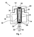
図1および図2には、全体を符号10で示した注入ポートが示されている。この注入ポートは、この実施例の場合には、ケーシング上部12およびケーシング下部14のツーピースから成るケーシングを備える。ケーシング下部14は、いわゆるルーアピン16の形態の接続部を備える。ケーシング下部14は、このルーアピンによって、ここでは詳細には示されていない分析装置の分析室に接続され得る。
1 and 2 show an injection port generally designated by
ケーシング上部12は、さらに、接続部18を備える。この接続部を介して、注入ポートが、圧力源、特に圧縮空気源に接続され得る。ケーシング内部は、これによって、請求項4に記載の加圧可能な室を構成する。注入ポートの機能方法については、図3の説明に関連してもう一度記載する。
The casing
ケーシング上部においては、ここでは詳しく示さないそれ自体公知の試料供給装置のカニューレのための、円錐形にテーパ状になっておりよって芯出しガイドを形成する開口部20の形態の入口が設けられている。ルーアピン16は、カニューレの出口に合流するとともに開口部20の延長上で装着されているケーシング上部12において存在する貫通孔22を有する。これによって、注入ポートを使用する際には、試料供給装置のカニューレが供給開口部20を介して注入ポート10を通過して通され得る。
In the upper part of the casing there is provided an inlet in the form of an
ケーシング上部12は、この実施例では気密にケーシング下部14にねじ止めされている。この目的のために、この実施例では、ケーシング下部14のある部分が雄ねじを有しており、ケーシング上部12のある部分がそれを相補する雌ねじを有している。当然、ケーシング部分をその他の方法で固定することも可能である。たとえば、フランジ接続である。ケーシング上部12およびケーシング下部14の示したねじ接続は、しかしながら、一方ではさらなる接続箇所なしで実現可能であり、かつ脱着可能であるという大きな利点を有し、それによって、ケーシング上部12のねじを解除することによってケーシング内に設けられている注入ポートの部分に手を入れることが可能になる。
The casing
ケーシングでは、入口20とルーアピン16との間に、弾性弁部材、ここではホースピース24の形態の弁部材が、支持管26によって、支持管26の開放端部両方に設けられている2つのホースアダプタ28とホースアダプタ28およびケーシングの間の2つのOリング30との間に設けられており、それによって、ホースピース24が自身の長手方向において開口部20を通ってルーアピン16まで延びている試料供給装置のカニューレによって横切られ得るようになっている。ここで、図2においては、上部12、上側Oリング30および上側ホースアダプタ28の画定線が示されていないという極めて概略化した上面図が示されているということを指摘しておく。
In the casing, two hoses are provided between the
支持管26には、少なくとも、線32によって示されている切り欠き部が、ホースピース24がケーシング内を占めている圧力比に直接さらされるように設けられている。ホースアダプタ28およびOリング30は、ホースピース24とともにケーシング内部をケーシングの外側から封止している。それによって、たとえば、接続部18を介してケーシング内部に導入されるガスまたは流体が開口部20または孔22を介して逃げることができないようになっている。この構成によって、ホースピース24をケーシング内の内圧を高めることによって圧搾して、それによって注入ポートによって形成されている、ここでは示していない分析装置の分析室への入口を閉鎖し、それによって大気が分析室に侵入することもなければたとえば分析の際に生じたガスが分析室から注入ポートを介して外へ侵出することもないようにすることが可能になる。ここで、入口は、カニューレがない場合にも、また、試料供給装置のカニューレが注入ポートを通じて導入されている場合にも、閉止され得る。その際、後者の場合には、ホースがカニューレの外側に緊密に当接しており、分析室は、当然カニューレを介して試料供給装置に接続される。この試料供給装置は、しかしながら、通常、分析室からのガスが試料供給装置を介して制御されずに逃げることがないようになっている。
The
ホースピース24の内径は、好適には、通常用いられるカニューレの外径よりも大きい寸法になっている。この場合、こうすることによって、ホースピースに圧力が印加されない場合、カニューレを非接触式にホースピースに通すことが可能になる。これによって、摩耗が生じることはない。このことによって、摩擦が生じることはなく、それによって、ホースピースの耐久年数が相当延長される。この構成において分析室はカニューレを導入している間に暫定的に注入ポートによって気密に閉止されていないことは、たいていの用途において損傷を与えない。カニューレを導入している際に実際に気密の閉止が所望の場合には、ケーシング内部の圧力を低減して、ホースピースが導入中にもカニューレに当接するようにし、しかしながらカニューレとホースピースとの間に過度に高い摩擦力が生じないようにする。
The inner diameter of the
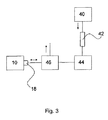
図3には、概略的に、注入ポート10の作動のための、詳細には、注入ポートに設けられている弁部材の作動のための可能な機構が示されている。この機構は、ここでは圧縮空気タンク40の形態の圧力源を有する。この圧縮空気タンクは、ここでは導管42の形態の流量制限装置と、バッファタンク44と、3/2ウェイバルブ46とを介して、注入ポート10の接続部18に接続されている。3/2ウェイバルブと対応のそれ自体公知の制御装置を介して、注入ポート10に設けられている弾性弁部材、すなわち図1に示したホースピースに、圧力を印加するかまたは負荷を軽減することによって弁部材が開閉する。弁部材を閉止するために過大な圧力を必要としないので、バッファタンク44を介して供給することができる。このことは、流量制限装置42とあいまって、機構をたとえば故障した弾性弁部材の場合に注入ポートにおいて過度の圧縮空気消費がないように保証することを可能にする。通常の分析装置のための注入ポートの寸法において約100mlの容量を有するバッファタンクには、流量制限装置によって、非常に制限された量の容量流しか注ぎたされない。これによって、注入ポート内の故障した弁部材において最大でも1時間当たり30lの空気量しか逃げないように保証される。
FIG. 3 schematically shows a possible mechanism for the operation of the
本発明の思想の範疇において、無数の変更と変形形態が可能である。これらは、たとえば、使用される弁部材の種類に関するものである。したがって、たとえば、外部圧力によって所望のやり方で圧搾される図示のホースピースの代わりに、弾性の二重壁の管部材を使用することが可能である。この管部材は、膨張または流体によって充填され、それによって自身の内径が所望のやり方で減少し、それによって、カニューレありまたはなしでの注入ポートに後置されている分析室への入口を閉止する。また、図示の開端した支持管のかわりに、たとえばU字形にホースピースを張設することも可能である。当業者にとっては、さらに、弾性弁部材の開閉の所望の効果が、弁部材が圧縮空気またはガスではなくて流体を供給された場合にも生じるということが明らかである。多くの場合には、しかしながら、ここで話題になっている形式の分析装置には、圧縮空気源が提供されているので、この圧縮空気源は注入ポートの弁部材の作動のために有利に使用することができる。 Numerous changes and modifications are possible within the scope of the idea of the present invention. These relate to the type of valve member used, for example. Thus, for example, instead of the illustrated hose piece being squeezed in the desired manner by external pressure, it is possible to use an elastic double-walled tube member. This tube member is inflated or filled with fluid, thereby reducing its internal diameter in the desired manner, thereby closing the inlet to the analysis chamber that is followed by the injection port with or without the cannula . Moreover, it is also possible to stretch a hose piece in, for example, a U shape instead of the illustrated open-ended support tube. It will also be apparent to those skilled in the art that the desired effect of opening and closing the elastic valve member also occurs when the valve member is supplied with fluid rather than compressed air or gas. In many cases, however, a source of compressed air is provided for the type of analyzer discussed here, which is advantageously used for the operation of the valve member of the injection port. can do.
Claims (14)
当該注入ポートは、少なくとも、制御下に開閉可能な弾性弁部材を有し、この弾性弁部材によって、分析室への入口が、カニューレが存在しない場合も注入ポートにカニューレが導入されている場合も封止され得るようになっていることを特徴とする、注入ポート。 An injection port for an analytical device, wherein the equalization port constitutes an inlet to the analytical chamber of the analytical device when attached to the analytical device as prescribed, and the sample having a sample to be analyzed at the inlet At the injection port, through which the cannula of the delivery device can pass
The injection port has at least an elastic valve member that can be opened and closed under control, and this elastic valve member allows the inlet to the analysis chamber to be in the absence or presence of the cannula. An injection port, characterized in that it can be sealed.
制御可能な弾性弁部材が水圧式にまたは空気圧式に作動可能であることを特徴とする、注入ポート。 The injection port according to claim 1,
An injection port, characterized in that the controllable elastic valve member is actuated hydraulically or pneumatically.
弁部材は、二重壁を有する管部材であり、この管部材を通って試料供給装置のカニューレが導入され得るとともにこの管部材の内径はガスまたは流体を充填することによって減少可能であることを特徴とする、注入ポート。 The injection port according to claim 1 or 2,
The valve member is a tube member having a double wall through which the sample supply device cannula can be introduced and the inner diameter of the tube member can be reduced by filling with gas or fluid. Features an injection port.
弁部材はホースピースであり、このホースピースを通って試料供給装置のカニューレが導入され得、ここで、ホースピースは、注入ポート内に設けられている流体またはガスによって加圧可能な室内に設けられており、それによって、ホースピースの内側が規定通りの取り付け状態において試料供給装置のカニューレのための入口を構成し、室を加圧することによって、カニューレがない場合に、分析室への入口を、ホースピースの圧搾によって閉止することができ、また、カニューレが導入されている場合に、ホースピースがカニューレに緊密に押し付けられることができるようになっていることを特徴とする、注入ポート。 The injection port according to claim 1 or 2,
The valve member is a hose piece through which the sample supply device cannula can be introduced, where the hose piece is provided in a chamber pressurizable by a fluid or gas provided in the injection port. So that the inside of the hose piece constitutes the inlet for the cannula of the sample supply device with the prescribed attachment, and by pressurizing the chamber, the inlet to the analysis chamber in the absence of the cannula An injection port, characterized in that it can be closed by squeezing the hose piece and, when the cannula is introduced, the hose piece can be pressed tightly against the cannula.
ホースピースが、開端した支持管またはU字状に張設されていることを特徴とする、注入ポート。 An injection port according to claim 4,
An injection port, wherein the hose piece is stretched in an open-ended support tube or U-shape.
注入ポートは、試料供給装置のカニューレのための入口および出口を備えるケーシングを備えることを特徴とする、注入ポート。 An injection port according to any one of claims 1 to 5,
An injection port, characterized in that the injection port comprises a casing with an inlet and an outlet for the cannula of the sample supply device.
ケーシングはツーピースで構成されており、ケーシングの一部を取り外すことができ、その際、注入ポートの全体が分析装置から取り外されることはなく、それによって弾性弁部材への入口を確保することを特徴とする、注入ポート。 An injection port according to claim 6, wherein
The casing is composed of two pieces, a part of the casing can be removed, the whole injection port is not removed from the analyzer device, thereby ensuring the inlet to the elastic valve member And the injection port.
弁部材は、3/2ウェイ弁を介して、弁部材に加圧された流体またはガスを印加するための圧力源に接続されており、
圧力源と3/2ウェイ弁の間に流量画定装置が設けられており、
流量画定装置と3/2ウェイ弁との間に加圧された流体またはガスのためのバッファタンクが挿入されていることを特徴とする、機構。 A mechanism for actuation of an injection port according to any one of claims 2 to 5,
The valve member is connected to a pressure source for applying pressurized fluid or gas to the valve member via a 3/2 way valve,
A flow defining device is provided between the pressure source and the 3/2 way valve;
A mechanism, characterized in that a buffer tank for pressurized fluid or gas is inserted between the flow-defining device and the 3 / 2-way valve.
圧力源は、圧縮空気源であり、流量画定装置は、導管であることを特徴とする、機構。 The mechanism according to claim 10, wherein
A mechanism, wherein the pressure source is a compressed air source and the flow defining device is a conduit.
注入ポートは、少なくとも制御下で開閉可能な弁部材を有しており、この弁部材によって、分析室への入口が、カニューレがない場合も注入ポートをカニューレが通っている場合も封止され得ることを特徴とする、分析装置。 An analysis device comprising an analysis chamber, wherein a sample to be analyzed can be introduced using a sample supply device comprising a cannula, and an inlet to the analysis chamber is formed through the injection port for the cannula In the analyzer,
The injection port has a valve member that can be opened and closed under control at least so that the inlet to the analysis chamber can be sealed both when the cannula is absent and when the cannula passes through the injection port. An analysis apparatus characterized by that.
注入ポートは請求項2ないし9に記載したように形成されていることを特徴とする、分析装置。 The analyzer according to claim 12, wherein
10. The analyzer according to claim 2, wherein the injection port is formed as described in claims 2-9.
さらに、請求項10または11に記載の注入ポートを作動させるための機構を有することを特徴とする、分析装置。 The analyzer according to claim 12 or 13,
Furthermore, it has a mechanism for operating the injection port of Claim 10 or 11, The analyzer characterized by the above-mentioned.
Applications Claiming Priority (2)
| Application Number | Priority Date | Filing Date | Title |
|---|---|---|---|
| DE102007036612A DE102007036612A1 (en) | 2007-08-02 | 2007-08-02 | Injection port for analyzers, arrangement for actuating an injection port and analyzer with an injection port |
| PCT/DE2008/001259 WO2009015656A1 (en) | 2007-08-02 | 2008-08-01 | Injection port for analysis appliances, device for actuating an injection port, and analysis appliance with an injection port |
Publications (2)
| Publication Number | Publication Date |
|---|---|
| JP2010535327A true JP2010535327A (en) | 2010-11-18 |
| JP2010535327A5 JP2010535327A5 (en) | 2011-09-15 |
Family
ID=40039963
Family Applications (1)
| Application Number | Title | Priority Date | Filing Date |
|---|---|---|---|
| JP2010518493A Pending JP2010535327A (en) | 2007-08-02 | 2008-08-01 | INJECTION PORT FOR ANALYSIS DEVICE, MECHANISM FOR OPERATING INJECTION PORT, AND ANALYSIS DEVICE HAVING INJECTION PORT |
Country Status (6)
| Country | Link |
|---|---|
| US (1) | US8677844B2 (en) |
| EP (1) | EP2174125B1 (en) |
| JP (1) | JP2010535327A (en) |
| DE (1) | DE102007036612A1 (en) |
| PL (1) | PL2174125T3 (en) |
| WO (1) | WO2009015656A1 (en) |
Cited By (1)
| Publication number | Priority date | Publication date | Assignee | Title |
|---|---|---|---|---|
| JP2015520852A (en) * | 2012-05-22 | 2015-07-23 | セドゥー ディアグノスチックスC2 Diagnostics | Fluid communication device for biological analyzer, suitable fluid component and biological analyzer with the same |
Families Citing this family (1)
| Publication number | Priority date | Publication date | Assignee | Title |
|---|---|---|---|---|
| US11467136B2 (en) * | 2017-12-20 | 2022-10-11 | Chromatography Research Supplies, Inc. | Chambered septum |
Citations (10)
| Publication number | Priority date | Publication date | Assignee | Title |
|---|---|---|---|---|
| JPS5167787U (en) * | 1974-11-21 | 1976-05-28 | ||
| JPS56101550A (en) * | 1980-01-02 | 1981-08-14 | Erba Strumentazione | Controllvalve for direct ion column injector path |
| JPS58129362A (en) * | 1982-01-26 | 1983-08-02 | バリアン・アソシエイツ・インコ−ポレイテツド | Injector for on-column capillary gas chromatograph |
| JPS5958361U (en) * | 1982-10-12 | 1984-04-16 | 株式会社島津製作所 | Sample injection port in chromatograph, etc. |
| JPH01191054A (en) * | 1987-11-28 | 1989-08-01 | Eberhard Gerstel | Sample injection or extraction head for gaseous or liquid fluid |
| US4915356A (en) * | 1988-06-20 | 1990-04-10 | Guild Lloyd V | Fluid valve |
| WO1991013349A1 (en) * | 1990-03-01 | 1991-09-05 | Jade Systems, Inc. | Probe inlet apparatus and method |
| JPH0638972A (en) * | 1992-07-28 | 1994-02-15 | Sumitomo Bakelite Co Ltd | Cannula needle |
| JPH07501961A (en) * | 1991-12-10 | 1995-03-02 | アボツト・ラボラトリーズ | Connection device with pre-slit seal |
| JPH09122066A (en) * | 1995-07-21 | 1997-05-13 | Ethicon Endo Surgery Inc | Endoscope type access assembly |
Family Cites Families (18)
| Publication number | Priority date | Publication date | Assignee | Title |
|---|---|---|---|---|
| DE1142087B (en) * | 1955-12-30 | 1963-01-03 | Renault | Self-acting valve |
| GB911712A (en) * | 1960-06-02 | 1962-11-28 | Megator Pumps Compressor | Improvements in non-return valves |
| CH472671A (en) * | 1968-11-04 | 1969-05-15 | Scholl Ag | Device for taking samples from a pressurized autoclave |
| DE7325554U (en) * | 1973-07-11 | 1974-09-26 | Siemens Ag | CHECK VALVE FOR GASES |
| US4022065A (en) * | 1976-02-19 | 1977-05-10 | Ramin James A | Calibrated sample delivery apparatus accommodating offset error |
| US4381019A (en) * | 1981-07-06 | 1983-04-26 | Sid Harvey, Inc. | Pressure responsive valve |
| AT392360B (en) * | 1987-04-28 | 1991-03-25 | Avl Verbrennungskraft Messtech | VALVE |
| DE3732515A1 (en) * | 1987-09-26 | 1989-04-06 | Joka Kathetertechnik Gmbh | DEVICE FOR INJECTING AND / OR REMOVING LIQUIDS |
| US4896545A (en) * | 1988-04-22 | 1990-01-30 | Dynatech Precision Sampling Corporation | Automatic fluid injector |
| US4954149A (en) * | 1989-10-25 | 1990-09-04 | Merlin Instrument Company | Injection septum |
| DE29709021U1 (en) * | 1997-05-22 | 1997-07-17 | Festo Kg | check valve |
| US6752965B2 (en) * | 1998-03-06 | 2004-06-22 | Abner Levy | Self resealing elastomeric closure |
| DE10043345C2 (en) * | 2000-08-24 | 2003-01-09 | Cybio Instr Gmbh | Device for fully automatic solid phase extraction |
| CH694999A5 (en) * | 2001-04-20 | 2005-10-31 | Rene Iff Creatiff Engineering | Sampling valve for the withdrawal of liquid or houses on gaseous samples from pipes or containers. |
| JP3780224B2 (en) * | 2002-04-30 | 2006-05-31 | Smc株式会社 | Check valve device |
| EP1656092B1 (en) | 2003-08-12 | 2008-07-23 | Philips Intellectual Property & Standards GmbH | Closure device for a container |
| DE202005016282U1 (en) * | 2005-10-18 | 2005-12-15 | Festo Ag & Co. | Valve unit, has closure head and compression spring unit that are compressed axially to form single piece construction unit, and actuator lifting head by compressing compression spring unit so that flowing of flow-medium takes place |
| BRPI0719528A2 (en) * | 2006-12-01 | 2013-12-31 | Koninkl Philips Electronics Nv | MALE INTERFACE MODULE, COUPLING SYSTEM, AND INSTRUMENT FOR PROCESSING A SAMPLE IN AN EXTERNAL SAMPLE CHAMBER. |
-
2007
- 2007-08-02 DE DE102007036612A patent/DE102007036612A1/en not_active Withdrawn
-
2008
- 2008-08-01 JP JP2010518493A patent/JP2010535327A/en active Pending
- 2008-08-01 PL PL08801097T patent/PL2174125T3/en unknown
- 2008-08-01 WO PCT/DE2008/001259 patent/WO2009015656A1/en active Application Filing
- 2008-08-01 EP EP08801097.0A patent/EP2174125B1/en active Active
- 2008-08-01 US US12/671,699 patent/US8677844B2/en active Active
Patent Citations (10)
| Publication number | Priority date | Publication date | Assignee | Title |
|---|---|---|---|---|
| JPS5167787U (en) * | 1974-11-21 | 1976-05-28 | ||
| JPS56101550A (en) * | 1980-01-02 | 1981-08-14 | Erba Strumentazione | Controllvalve for direct ion column injector path |
| JPS58129362A (en) * | 1982-01-26 | 1983-08-02 | バリアン・アソシエイツ・インコ−ポレイテツド | Injector for on-column capillary gas chromatograph |
| JPS5958361U (en) * | 1982-10-12 | 1984-04-16 | 株式会社島津製作所 | Sample injection port in chromatograph, etc. |
| JPH01191054A (en) * | 1987-11-28 | 1989-08-01 | Eberhard Gerstel | Sample injection or extraction head for gaseous or liquid fluid |
| US4915356A (en) * | 1988-06-20 | 1990-04-10 | Guild Lloyd V | Fluid valve |
| WO1991013349A1 (en) * | 1990-03-01 | 1991-09-05 | Jade Systems, Inc. | Probe inlet apparatus and method |
| JPH07501961A (en) * | 1991-12-10 | 1995-03-02 | アボツト・ラボラトリーズ | Connection device with pre-slit seal |
| JPH0638972A (en) * | 1992-07-28 | 1994-02-15 | Sumitomo Bakelite Co Ltd | Cannula needle |
| JPH09122066A (en) * | 1995-07-21 | 1997-05-13 | Ethicon Endo Surgery Inc | Endoscope type access assembly |
Cited By (1)
| Publication number | Priority date | Publication date | Assignee | Title |
|---|---|---|---|---|
| JP2015520852A (en) * | 2012-05-22 | 2015-07-23 | セドゥー ディアグノスチックスC2 Diagnostics | Fluid communication device for biological analyzer, suitable fluid component and biological analyzer with the same |
Also Published As
| Publication number | Publication date |
|---|---|
| PL2174125T3 (en) | 2014-09-30 |
| EP2174125A1 (en) | 2010-04-14 |
| WO2009015656A1 (en) | 2009-02-05 |
| US20110088458A1 (en) | 2011-04-21 |
| EP2174125B1 (en) | 2014-03-12 |
| DE102007036612A1 (en) | 2009-02-05 |
| US8677844B2 (en) | 2014-03-25 |
Similar Documents
| Publication | Publication Date | Title |
|---|---|---|
| JPH0311658B2 (en) | ||
| KR20070080563A (en) | Apparatus for bringing out tire sealing material from container | |
| US4873876A (en) | Chemical process sampler | |
| US20040123679A1 (en) | Gas sampling apparatus | |
| JP2010535327A (en) | INJECTION PORT FOR ANALYSIS DEVICE, MECHANISM FOR OPERATING INJECTION PORT, AND ANALYSIS DEVICE HAVING INJECTION PORT | |
| US4213342A (en) | Liquid sampler device | |
| CN107850009B (en) | Gas valve unit and the method that pressure test is executed to gas valve unit | |
| WO2004034008A1 (en) | Reference leakage device for leak snifter detector | |
| CN208432444U (en) | Solution gas negative pressure sampler | |
| EP0070404B1 (en) | A method and equipment to perform porosimetric analyses | |
| US2414113A (en) | Test means for high-pressure fluid medium containers | |
| WO2018001167A1 (en) | Automatic calorimeter for calorific value analysis of sample | |
| CN108693284A (en) | A kind of gas chromatograph for determination gas component sample injection method and device | |
| US4915356A (en) | Fluid valve | |
| US6230573B1 (en) | Device for sampling gas | |
| CN108426752A (en) | Solution gas negative pressure sampler | |
| US5578770A (en) | Apparatus and method for gas detection | |
| CN104359716B (en) | A kind of device that medium in pressure vessel can be carried out sampling with pressure | |
| KR200471117Y1 (en) | air breather test apparatus | |
| JP2010535327A5 (en) | ||
| CN206676235U (en) | Filter | |
| US20210298640A1 (en) | Apparatus for storing a sample of human breath, and corresponding method for storing a sample of human breath | |
| CN112198004A (en) | Online airtight buffer memory sampler | |
| CN109085860A (en) | Liquid supply device and detection device | |
| CN209875980U (en) | On-line sampling valve |
Legal Events
| Date | Code | Title | Description |
|---|---|---|---|
| A521 | Request for written amendment filed |
Free format text: JAPANESE INTERMEDIATE CODE: A523 Effective date: 20110801 |
|
| A621 | Written request for application examination |
Free format text: JAPANESE INTERMEDIATE CODE: A621 Effective date: 20110801 |
|
| A521 | Request for written amendment filed |
Free format text: JAPANESE INTERMEDIATE CODE: A523 Effective date: 20121002 |
|
| A977 | Report on retrieval |
Free format text: JAPANESE INTERMEDIATE CODE: A971007 Effective date: 20130404 |
|
| A131 | Notification of reasons for refusal |
Free format text: JAPANESE INTERMEDIATE CODE: A131 Effective date: 20130416 |
|
| A02 | Decision of refusal |
Free format text: JAPANESE INTERMEDIATE CODE: A02 Effective date: 20131008 |