EP1656092B1 - Closure device for a container - Google Patents
Closure device for a container Download PDFInfo
- Publication number
- EP1656092B1 EP1656092B1 EP20040744725 EP04744725A EP1656092B1 EP 1656092 B1 EP1656092 B1 EP 1656092B1 EP 20040744725 EP20040744725 EP 20040744725 EP 04744725 A EP04744725 A EP 04744725A EP 1656092 B1 EP1656092 B1 EP 1656092B1
- Authority
- EP
- European Patent Office
- Prior art keywords
- closure
- container
- closure device
- closure means
- membrane
- Prior art date
- Legal status (The legal status is an assumption and is not a legal conclusion. Google has not performed a legal analysis and makes no representation as to the accuracy of the status listed.)
- Expired - Lifetime
Links
- -1 polytetrafluoroethylene Polymers 0.000 claims abstract description 30
- 229920001343 polytetrafluoroethylene Polymers 0.000 claims abstract description 29
- 239000004810 polytetrafluoroethylene Substances 0.000 claims abstract description 29
- 239000012528 membrane Substances 0.000 claims abstract description 28
- 239000011248 coating agent Substances 0.000 claims description 26
- 238000000576 coating method Methods 0.000 claims description 26
- 210000001124 body fluid Anatomy 0.000 claims description 16
- 239000010839 body fluid Substances 0.000 claims description 16
- 229920001296 polysiloxane Polymers 0.000 claims description 5
- 239000000463 material Substances 0.000 claims description 4
- 239000012530 fluid Substances 0.000 claims description 3
- 230000001070 adhesive effect Effects 0.000 claims description 2
- 239000007779 soft material Substances 0.000 claims description 2
- 241000405070 Percophidae Species 0.000 abstract 1
- 239000008280 blood Substances 0.000 description 12
- 210000004369 blood Anatomy 0.000 description 12
- 238000012123 point-of-care testing Methods 0.000 description 7
- 238000004458 analytical method Methods 0.000 description 6
- 238000007789 sealing Methods 0.000 description 5
- 239000012620 biological material Substances 0.000 description 3
- 238000002347 injection Methods 0.000 description 3
- 239000007924 injection Substances 0.000 description 3
- 230000000694 effects Effects 0.000 description 2
- 230000003203 everyday effect Effects 0.000 description 2
- 238000011065 in-situ storage Methods 0.000 description 2
- 239000004809 Teflon Substances 0.000 description 1
- 229920006362 Teflon® Polymers 0.000 description 1
- 238000004159 blood analysis Methods 0.000 description 1
- 230000001419 dependent effect Effects 0.000 description 1
- 239000000243 solution Substances 0.000 description 1
- 239000000126 substance Substances 0.000 description 1
- 239000000725 suspension Substances 0.000 description 1
- 238000012360 testing method Methods 0.000 description 1
Images
Classifications
-
- A—HUMAN NECESSITIES
- A61—MEDICAL OR VETERINARY SCIENCE; HYGIENE
- A61J—CONTAINERS SPECIALLY ADAPTED FOR MEDICAL OR PHARMACEUTICAL PURPOSES; DEVICES OR METHODS SPECIALLY ADAPTED FOR BRINGING PHARMACEUTICAL PRODUCTS INTO PARTICULAR PHYSICAL OR ADMINISTERING FORMS; DEVICES FOR ADMINISTERING FOOD OR MEDICINES ORALLY; BABY COMFORTERS; DEVICES FOR RECEIVING SPITTLE
- A61J1/00—Containers specially adapted for medical or pharmaceutical purposes
- A61J1/14—Details; Accessories therefor
- A61J1/1406—Septums, pierceable membranes
-
- B—PERFORMING OPERATIONS; TRANSPORTING
- B01—PHYSICAL OR CHEMICAL PROCESSES OR APPARATUS IN GENERAL
- B01L—CHEMICAL OR PHYSICAL LABORATORY APPARATUS FOR GENERAL USE
- B01L3/00—Containers or dishes for laboratory use, e.g. laboratory glassware; Droppers
- B01L3/50—Containers for the purpose of retaining a material to be analysed, e.g. test tubes
- B01L3/508—Containers for the purpose of retaining a material to be analysed, e.g. test tubes rigid containers not provided for above
- B01L3/5082—Test tubes per se
- B01L3/50825—Closing or opening means, corks, bungs
-
- B—PERFORMING OPERATIONS; TRANSPORTING
- B01—PHYSICAL OR CHEMICAL PROCESSES OR APPARATUS IN GENERAL
- B01L—CHEMICAL OR PHYSICAL LABORATORY APPARATUS FOR GENERAL USE
- B01L2200/00—Solutions for specific problems relating to chemical or physical laboratory apparatus
- B01L2200/02—Adapting objects or devices to another
- B01L2200/026—Fluid interfacing between devices or objects, e.g. connectors, inlet details
-
- B—PERFORMING OPERATIONS; TRANSPORTING
- B01—PHYSICAL OR CHEMICAL PROCESSES OR APPARATUS IN GENERAL
- B01L—CHEMICAL OR PHYSICAL LABORATORY APPARATUS FOR GENERAL USE
- B01L2300/00—Additional constructional details
- B01L2300/04—Closures and closing means
- B01L2300/041—Connecting closures to device or container
- B01L2300/042—Caps; Plugs
-
- B—PERFORMING OPERATIONS; TRANSPORTING
- B01—PHYSICAL OR CHEMICAL PROCESSES OR APPARATUS IN GENERAL
- B01L—CHEMICAL OR PHYSICAL LABORATORY APPARATUS FOR GENERAL USE
- B01L2300/00—Additional constructional details
- B01L2300/04—Closures and closing means
- B01L2300/041—Connecting closures to device or container
- B01L2300/044—Connecting closures to device or container pierceable, e.g. films, membranes
-
- B—PERFORMING OPERATIONS; TRANSPORTING
- B01—PHYSICAL OR CHEMICAL PROCESSES OR APPARATUS IN GENERAL
- B01L—CHEMICAL OR PHYSICAL LABORATORY APPARATUS FOR GENERAL USE
- B01L2300/00—Additional constructional details
- B01L2300/04—Closures and closing means
- B01L2300/046—Function or devices integrated in the closure
- B01L2300/049—Valves integrated in closure
-
- B—PERFORMING OPERATIONS; TRANSPORTING
- B01—PHYSICAL OR CHEMICAL PROCESSES OR APPARATUS IN GENERAL
- B01L—CHEMICAL OR PHYSICAL LABORATORY APPARATUS FOR GENERAL USE
- B01L2400/00—Moving or stopping fluids
- B01L2400/06—Valves, specific forms thereof
- B01L2400/0605—Valves, specific forms thereof check valves
- B01L2400/0611—Valves, specific forms thereof check valves duck bill valves
-
- Y—GENERAL TAGGING OF NEW TECHNOLOGICAL DEVELOPMENTS; GENERAL TAGGING OF CROSS-SECTIONAL TECHNOLOGIES SPANNING OVER SEVERAL SECTIONS OF THE IPC; TECHNICAL SUBJECTS COVERED BY FORMER USPC CROSS-REFERENCE ART COLLECTIONS [XRACs] AND DIGESTS
- Y10—TECHNICAL SUBJECTS COVERED BY FORMER USPC
- Y10T—TECHNICAL SUBJECTS COVERED BY FORMER US CLASSIFICATION
- Y10T137/00—Fluid handling
- Y10T137/9247—With closure
Definitions
- the invention relates to a closure device for a container as claimed in claim 1.
- POCT point of care testing
- a POCT analysis device in the vicinity of the patient, for example in the hospital ward that is caring for the patient. This can substantially accelerate the analysis and assessment of the blood sample.
- Automatic analytical means that comprise computer-controlled sensor systems for analyzing a biological material fed in are increasingly used for analysis and assessment.
- POCT systems are preferably used to analyze and assess body fluids, such as, for example, blood samples.
- body fluids such as, for example, blood samples.
- a sample of a body fluid to be analyzed is introduced into a container that is in turn inserted into an analytical or assessment device.
- the analytical or assessment device can then remove certain amounts of the sample contained in the container from the container for analysis and assessment.
- a patient's blood samples can be directly analyzed in situ by means of such containers.
- the containers provided for this purpose have special devices for receiving the blood to be analyzed.
- the manufacturers of such containers use various configurations of the containers and the receiving devices for a blood sample. For example, some manufacturers use paper filters for receiving blood, whereas others use a Luer closure or a closable sample inlet seal.
- US 6,039,718 discloses a universal connector having a type of needle guide and integrated membrane that can be pierced by an injection-needle tip or a Luer syringe.
- the invention relates to a closure device for a container that comprises the features of the preamble of claim 1.
- the closure device can preferably be pierced with a sharp object, in particular with an injection-needle tip.
- a sample can be introduced into the container without removing the closure means of the container.
- the closure means is formed in such a way that it can be sealed again, that is to say, for example because of its elastic properties, the closure means re-forms again, in particular, at the pierced point when the sharp object that has pierced the closure means is removed again.
- the reformation should take place in such a way that the pierced point is sealed so that no fluid can reach the outside from the interior of the container through the closure means.
- the sealing is substantially improved by coating the closure means with polytetrafluoroethylene.
- the closure means is a membrane. However, it may also be a septum.
- the closure means is a "duck-bill" valve device. In principle, such a valve device can be repeatedly used again, whereas a membrane or a septum must be replaced after a certain time of use, in particular after it has been pierced several times, in order to continue to seal the container in a fluid-tight manner.
- the polytetrafluoroethylene coating can be formed on the closure means in such a way that it covers a region of the side of the closure means that is provided for piercing with a sharp object. As a result, it is unnecessary to coat the entire closure means or large regions of the closure means with polytetrafluoroethylene. In principle, it is sufficient if only a small region of the closure means is provided with the polytetrafluoroethylene coating. The remaining regions of the closure means should then be protected in such a way that they cannot be pierced by a sharp object that serves to introduce a sample into the container.
- the closure means itself is composed of silicone. Because of its properties, silicone proves to be particularly suitable for sealing a container and can easily be pierced by a sharp object, such as, for example, a needle tip.
- the closure means has a first region that comprises soft material having good adhesive properties. Furthermore, it comprises a second region that encloses the first region and comprises hard material.
- the first region is preferably coated with polytetrafluoroethylene and is provided for piercing.
- the second region serves as a type of suspension for the first region and cannot be pierced because of its hardness.
- the second region preferably the hard material of the second region, can be formed in such a way that it has resilient properties. Said resilient properties prove advantageous when the membrane is pierced by a needle tip since the first region yields when pressure is applied by the needle. The yielding forms a kind of guiding depression for the needle tip, which reduces the danger of the needle tip slipping off the membrane, in particular if the needle tip strikes the closure means at an unfavorable angle.
- the filling device may have a Luer closure device that can be attached to the opening of the container.
- a closure device makes possible a simple and easily manipulated attachment of the closure device to the container.
- the closure device has a collecting space for receiving a sample of a biological material, such as, for example, a body fluid, that can be introduced into the collecting space through the closure means.
- the collecting space serves, so to speak, as a buffer space so that a more rapid filling of fluid into the container is made possible.
- a body fluid sample can be introduced, for example, by an injection syringe by means of an injection needle into the collecting space of the closure device in order then to flow from said collecting space into the container through the opening.
- the invention relates to the use of a closure device in accordance with the invention in a preferably automatic analytical device for body fluids.
- a closure means of the closure device has a coating containing polytetrafluoroethylene.
- Polytetrafluoroethylene also known under the trade name of Teflon, has advantageous properties, in particular for use in the medical sector, such as resistance to almost all chemicals, temperature resistance and low wettability.
- Polytetrafluoroethylene also improves the sealing action of the closure means, in particular after it has been pierced by an injection-needle tip.
- polytetrafluoroethylene has good anti-friction properties so that, for example, an injection-needle tip can pierce the closure means particularly well.
- the closure device 10 shown in Fig. 1 serves to fill a container 12 shown by dotted lines, in particular a small tube for body fluids that can be introduced into an analytical means for body fluids.
- the closure device 10 comprises a filling device 14 that has, in cross section, roughly the shape of a beaker.
- the filling device 14 comprises a Luer closure device 15 that is introduced into an opening 16 of the container 12 and is thereby attached to the container 12. Furthermore, the filling device 14 opens a collecting space 100 for receiving a body fluid introduced into the filling device 14.
- the collecting space 100 of the filling device 14 is opened by the Luer closure device 15 so that a body fluid it contains can flow into the container 12 through the Luer closure device 15.
- the collecting space 100 is furthermore sealed in a fluid-tight manner on one side by a membrane 18.
- the membrane 18 is composed of silicone.
- an injection-needle tip 24 pierces the polytetrafluoroethylene coating 22 and the membrane 20.
- the membrane 18, which is composed of silicone automatically seals in a fluid-tight manner because of the polytetrafluoroethylene coating 22 and its elastic properties.
- the body fluid contained in the collecting space can no longer escape to the outside through the membrane 12, but can only flow into the container 12 through the Luer closure device 15.
- the membrane is fixed on the filling device 14 by a ring fastener 26 that is composed, for example, of an elastic polymeric material.
- the ring fastener 26 makes possible an easy replacement of the membrane 18, for example if the membrane has already been pierced very often and has to be replaced for the closure device 10 to be used again.
- the coating 22 has, in addition, the effect that the injection-needle tip 24 slides easily and, because of its sealing properties, effectively prevents body fluid flowing through the injection-needle tip 24 into the collecting space 100 from being able to escape from the collecting space 100 at the pierced point 18 of the membrane.
- the coating 22 has the effect that, after the injection-needle tip 24 is removed from the membrane 18, the automatic sealing of the membrane 18 is improved.
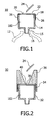
- Fig. 2 shows a closure device 30 that resembles the closure device 10 of Fig. 1 , but has a septum 34 as closure means for the collecting space 102 of a filling device 32 of the closure device 30 instead of the membrane 18.
- the septum 34 is fixed to the filling device 32 by means of a needle-guiding device 36.
- the needle-guiding device 36 is partially pushed over the filling device 32 in such a way that the septum 34 is clamped between a part of the needle-guiding device 36 and the outer wall of the filling device 32.
- the septum 34 has a smaller area that is provided with a polytetrafluoroethylene coating 38 on its outer side 40, that is to say on its side remote from the collecting space 102. Said smaller coated region of the outer side 40 of the septum 34 is necessary because the needle-guiding device 36 guides an injection-needle tip 24 for piercing the septum 34 to said region.
- the needle-guiding device 36 has a funnel-shaped cross section for this purpose. Because of said funnel-shaped cross section, the opening for introducing a needle tip to pierce the septum 34 is about as large as that area of the membrane 18 of the closure device 10 of Fig. 1 that is available for the piercing.
- this closure device can therefore be manipulated conveniently, just like the closure device 10 of Fig. 1 .
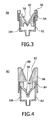
- Fig. 3 shows a closure device 50 that, in contrast to the closure devices 10 and 30 of Figs. 1 and 2 , does not have a membrane and a septum for piercing, but has a "duck-bill" closure device 54 (duck-bill valve).
- Said "duck-bill" closure device 54 is provided on its outer side 58, that is to say the side remote from a collection space 104 of the closure device 50, with a polytetrafluoroethylene coating 60.
- the coating 60 almost completely covers the outward-facing region of the "duck-bill" valve device 54.
- the "duck-bill" valve device 54 is clamped by means of a ring fastening 56 on a filling device 52 of the closure device 50.
- ring fastening 56 should be capable of being released again from the filling device 52 in order to be able to replace the "duck-bill" valve device 54.
- FIG. 4 shows a further closure device 80 in accordance with the invention that likewise has a "duck-bill" valve device 84.
- the "duck-bill" valve device 84 is mounted in a clamping fashion on a filling device 82 of the closure device 80 by means of a needle-guiding device 86.
- the needle-guiding device 86 has a polytetrafluoroethylene coating 88 on its outer side 92, that is to say that side of the needle-guiding device 86 that is accessible, for example, for an injection-needle tip.
- the "duck-bill" valve device 84 likewise has a polytetrafluoroethylene coating 90 on its outer side 94. Because of the design of the needle-guiding device 86, however, it is not necessary for the entire outer side 94 of the "duck-bill" valve device to be provided with the polytetrafluoroethylene coating 90. On the contrary, it is sufficient if only that region of the outer side 94 of the "duck-bill" valve device that is accessible for an injection-needle tip because of the needle-guiding device 86 is provided with the polytetrafluoroethylene coating 90.
- the polytetrafluoroethylene coating 88 of the needle-guiding device 86 is not absolutely necessary, but facilitates the manipulation of the closure device 80 since the injection-needle tip can then slide particularly well over the polytetrafluoroethylene coating 88 of the needle-guiding device 86.
Landscapes
- Health & Medical Sciences (AREA)
- General Health & Medical Sciences (AREA)
- Chemical & Material Sciences (AREA)
- Life Sciences & Earth Sciences (AREA)
- Public Health (AREA)
- Clinical Laboratory Science (AREA)
- Chemical Kinetics & Catalysis (AREA)
- Pharmacology & Pharmacy (AREA)
- Analytical Chemistry (AREA)
- Animal Behavior & Ethology (AREA)
- Hematology (AREA)
- Veterinary Medicine (AREA)
- Infusion, Injection, And Reservoir Apparatuses (AREA)
- Medical Preparation Storing Or Oral Administration Devices (AREA)
- Supplying Of Containers To The Packaging Station (AREA)
- Closing Of Containers (AREA)
- Basic Packing Technique (AREA)
- Closures For Containers (AREA)
Abstract
Description
- The invention relates to a closure device for a container as claimed in claim 1.
- In the medical sector, so-called point of care testing (POCT) has become ever more widespread in recent years. POCT is understood as meaning the testing and the analysis of biological material at the point of care or, in other words, in situ, such as, for example, in a hospital at a patient's bed. Whereas blood samples were previously taken from a patient and sent to a laboratory for analysis, it is nowadays possible by means of POCT to analyze and assess such a blood sample by means of a POCT analysis device in the vicinity of the patient, for example in the hospital ward that is caring for the patient. This can substantially accelerate the analysis and assessment of the blood sample. Automatic analytical means that comprise computer-controlled sensor systems for analyzing a biological material fed in are increasingly used for analysis and assessment.
- In everyday clinical practice, POCT systems are preferably used to analyze and assess body fluids, such as, for example, blood samples. For this purpose, a sample of a body fluid to be analyzed is introduced into a container that is in turn inserted into an analytical or assessment device. The analytical or assessment device can then remove certain amounts of the sample contained in the container from the container for analysis and assessment.
- In the field of POCT blood analysis, a patient's blood samples can be directly analyzed in situ by means of such containers. Typically, the containers provided for this purpose have special devices for receiving the blood to be analyzed. In this connection, the manufacturers of such containers use various configurations of the containers and the receiving devices for a blood sample. For example, some manufacturers use paper filters for receiving blood, whereas others use a Luer closure or a closable sample inlet seal.
- Common to almost all configurations of containers is, however, the fact that the filling of a blood sample into a receiving device is not without danger for a user since, in the known containers, blood can rapidly spatter over the container or, still worse, over the user, for example, if the user does not find the inlet opening of the container precisely with the needle tip of the injection needle containing a blood sample. This frequently occurs, in particular, in the case of containers in which only a very narrow filling opening is provided, for example, for blood samples.
- Various solutions are disclosed in the prior art that are intended, in particular, to facilitate the guiding of an injection-needle tip when filling a sample of a body fluid into a container. For example,
US 6,039,718 discloses a universal connector having a type of needle guide and integrated membrane that can be pierced by an injection-needle tip or a Luer syringe. - It is therefore an object of the present invention to propose a closure device for a container that improves the needle-guiding device or closure device for containers disclosed in
US 6,039,718 . - This object is achieved by a closure device for a container having the features as claimed in claim 1. Preferred embodiments of the invention emerge from the dependent claims.
- The invention relates to a closure device for a container that comprises the features of the preamble of claim 1.
- The closure device can preferably be pierced with a sharp object, in particular with an injection-needle tip. As a result, a sample can be introduced into the container without removing the closure means of the container. Preferably, the closure means is formed in such a way that it can be sealed again, that is to say, for example because of its elastic properties, the closure means re-forms again, in particular, at the pierced point when the sharp object that has pierced the closure means is removed again. In this connection, the reformation should take place in such a way that the pierced point is sealed so that no fluid can reach the outside from the interior of the container through the closure means. As already indicated above, the sealing is substantially improved by coating the closure means with polytetrafluoroethylene.
- Preferably, the closure means is a membrane. However, it may also be a septum. In a preferred embodiment, the closure means is a "duck-bill" valve device. In principle, such a valve device can be repeatedly used again, whereas a membrane or a septum must be replaced after a certain time of use, in particular after it has been pierced several times, in order to continue to seal the container in a fluid-tight manner.
- The polytetrafluoroethylene coating can be formed on the closure means in such a way that it covers a region of the side of the closure means that is provided for piercing with a sharp object. As a result, it is unnecessary to coat the entire closure means or large regions of the closure means with polytetrafluoroethylene. In principle, it is sufficient if only a small region of the closure means is provided with the polytetrafluoroethylene coating. The remaining regions of the closure means should then be protected in such a way that they cannot be pierced by a sharp object that serves to introduce a sample into the container.
- Preferably, the closure means itself is composed of silicone. Because of its properties, silicone proves to be particularly suitable for sealing a container and can easily be pierced by a sharp object, such as, for example, a needle tip.
- In accordance with a particularly preferred embodiment, the closure means has a first region that comprises soft material having good adhesive properties. Furthermore, it comprises a second region that encloses the first region and comprises hard material. In the case of this structure, the first region is preferably coated with polytetrafluoroethylene and is provided for piercing. On the other hand, the second region serves as a type of suspension for the first region and cannot be pierced because of its hardness. Preferably, the second region, preferably the hard material of the second region, can be formed in such a way that it has resilient properties. Said resilient properties prove advantageous when the membrane is pierced by a needle tip since the first region yields when pressure is applied by the needle. The yielding forms a kind of guiding depression for the needle tip, which reduces the danger of the needle tip slipping off the membrane, in particular if the needle tip strikes the closure means at an unfavorable angle.
- The filling device may have a Luer closure device that can be attached to the opening of the container. Such a closure device makes possible a simple and easily manipulated attachment of the closure device to the container.
- In order to facilitate the filling of body fluid into the container through the closure device, the closure device has a collecting space for receiving a sample of a biological material, such as, for example, a body fluid, that can be introduced into the collecting space through the closure means. The collecting space serves, so to speak, as a buffer space so that a more rapid filling of fluid into the container is made possible. Typically, a body fluid sample can be introduced, for example, by an injection syringe by means of an injection needle into the collecting space of the closure device in order then to flow from said collecting space into the container through the opening.
- Finally, the invention relates to the use of a closure device in accordance with the invention in a preferably automatic analytical device for body fluids.
- An important idea of the invention is therefore that a closure means of the closure device has a coating containing polytetrafluoroethylene. Polytetrafluoroethylene, also known under the trade name of Teflon, has advantageous properties, in particular for use in the medical sector, such as resistance to almost all chemicals, temperature resistance and low wettability. Polytetrafluoroethylene also improves the sealing action of the closure means, in particular after it has been pierced by an injection-needle tip. Finally, polytetrafluoroethylene has good anti-friction properties so that, for example, an injection-needle tip can pierce the closure means particularly well. The manipulation of a closure device that is formed in accordance with the invention is therefore substantially simplified, particularly in everyday clinical practice.
- These and other aspects of the invention are apparent from and will be elucidated with reference to the embodiments described hereinafter.
- In the drawings:
-
Fig. 1 shows a first exemplary embodiment of a closure device in accordance with the invention; -
Fig. 2 shows a second exemplary embodiment of a closure device in accordance with the invention having a needle-guiding device; -
Fig. 3 shows a third exemplary embodiment of a closure device in accordance with the invention having a "duck-bill" valve device; and -
Fig. 4 shows a fourth exemplary embodiment of a closure device in accordance with the invention having a needle-guiding device and a "duck-bill" valve device. - The
closure device 10 shown inFig. 1 serves to fill acontainer 12 shown by dotted lines, in particular a small tube for body fluids that can be introduced into an analytical means for body fluids. - The
closure device 10 comprises afilling device 14 that has, in cross section, roughly the shape of a beaker. Thefilling device 14 comprises aLuer closure device 15 that is introduced into anopening 16 of thecontainer 12 and is thereby attached to thecontainer 12. Furthermore, thefilling device 14 opens a collectingspace 100 for receiving a body fluid introduced into thefilling device 14. - The collecting
space 100 of thefilling device 14 is opened by theLuer closure device 15 so that a body fluid it contains can flow into thecontainer 12 through theLuer closure device 15. The collectingspace 100 is furthermore sealed in a fluid-tight manner on one side by amembrane 18. Themembrane 18 is composed of silicone. - The outer side of the
membrane 18, that is to say thatside 20 of themembrane 18 that is remote from the collectingspace 100, is provided with apolytetrafluoroethylene coating 22. To introduce the body fluid, an injection-needle tip 24 pierces thepolytetrafluoroethylene coating 22 and themembrane 20. After the injection-needle tip 24 is withdrawn from themembrane 18 and thecoating 22, themembrane 18, which is composed of silicone, automatically seals in a fluid-tight manner because of thepolytetrafluoroethylene coating 22 and its elastic properties. As a result, the body fluid contained in the collecting space can no longer escape to the outside through themembrane 12, but can only flow into thecontainer 12 through theLuer closure device 15. - The membrane is fixed on the filling
device 14 by aring fastener 26 that is composed, for example, of an elastic polymeric material. Thering fastener 26 makes possible an easy replacement of themembrane 18, for example if the membrane has already been pierced very often and has to be replaced for theclosure device 10 to be used again. - Because of the low wettability of the
polytetrafluoroethylene coating 22, if the injection-needle tip 24 slides off the membrane, there is little danger that body fluid escaping from the injection-needle tip 24 is spattered over theentire device 10. In the pierced state of themembrane 18, thecoating 22 has, in addition, the effect that the injection-needle tip 24 slides easily and, because of its sealing properties, effectively prevents body fluid flowing through the injection-needle tip 24 into the collectingspace 100 from being able to escape from the collectingspace 100 at thepierced point 18 of the membrane. Finally, thecoating 22 has the effect that, after the injection-needle tip 24 is removed from themembrane 18, the automatic sealing of themembrane 18 is improved. -
Fig. 2 shows aclosure device 30 that resembles theclosure device 10 ofFig. 1 , but has aseptum 34 as closure means for the collectingspace 102 of a fillingdevice 32 of theclosure device 30 instead of themembrane 18. Theseptum 34 is fixed to the fillingdevice 32 by means of a needle-guidingdevice 36. For this purpose, the needle-guidingdevice 36 is partially pushed over the fillingdevice 32 in such a way that theseptum 34 is clamped between a part of the needle-guidingdevice 36 and the outer wall of the fillingdevice 32. - Likewise in contrast to the
closure device 10 shown inFig. 1 , theseptum 34 has a smaller area that is provided with apolytetrafluoroethylene coating 38 on itsouter side 40, that is to say on its side remote from the collectingspace 102. Said smaller coated region of theouter side 40 of theseptum 34 is necessary because the needle-guidingdevice 36 guides an injection-needle tip 24 for piercing theseptum 34 to said region. As is shown inFig. 2 , the needle-guidingdevice 36 has a funnel-shaped cross section for this purpose. Because of said funnel-shaped cross section, the opening for introducing a needle tip to pierce theseptum 34 is about as large as that area of themembrane 18 of theclosure device 10 ofFig. 1 that is available for the piercing. Despite the needle-guidingdevice 36 used in theclosure device 30, this closure device can therefore be manipulated conveniently, just like theclosure device 10 ofFig. 1 . -
Fig. 3 shows aclosure device 50 that, in contrast to theclosure devices Figs. 1 and 2 , does not have a membrane and a septum for piercing, but has a "duck-bill" closure device 54 (duck-bill valve). Said "duck-bill"closure device 54 is provided on itsouter side 58, that is to say the side remote from acollection space 104 of theclosure device 50, with apolytetrafluoroethylene coating 60. Thecoating 60 almost completely covers the outward-facing region of the "duck-bill"valve device 54. The "duck-bill"valve device 54 is clamped by means of a ring fastening 56 on a fillingdevice 52 of theclosure device 50. Other joints between ring fastening 56 and fillingdevice 52, for example a screw joint or a snap joint, are of course conceivable. Thering fastening 56 should be capable of being released again from the fillingdevice 52 in order to be able to replace the "duck-bill"valve device 54. - Finally,
Fig. 4 shows afurther closure device 80 in accordance with the invention that likewise has a "duck-bill"valve device 84. In contrast to theclosure device 50 shown inFig. 3 , in the case of saidclosure device 80, the "duck-bill"valve device 84 is mounted in a clamping fashion on a fillingdevice 82 of theclosure device 80 by means of a needle-guidingdevice 86. The needle-guidingdevice 86 has apolytetrafluoroethylene coating 88 on itsouter side 92, that is to say that side of the needle-guidingdevice 86 that is accessible, for example, for an injection-needle tip. The "duck-bill"valve device 84 likewise has apolytetrafluoroethylene coating 90 on itsouter side 94. Because of the design of the needle-guidingdevice 86, however, it is not necessary for the entireouter side 94 of the "duck-bill" valve device to be provided with thepolytetrafluoroethylene coating 90. On the contrary, it is sufficient if only that region of theouter side 94 of the "duck-bill" valve device that is accessible for an injection-needle tip because of the needle-guidingdevice 86 is provided with thepolytetrafluoroethylene coating 90. Thepolytetrafluoroethylene coating 88 of the needle-guidingdevice 86 is not absolutely necessary, but facilitates the manipulation of theclosure device 80 since the injection-needle tip can then slide particularly well over thepolytetrafluoroethylene coating 88 of the needle-guidingdevice 86. -
- 10
- First closure device
- 12
- Clinical container
- 14
- Filling device
- 15
- Luer closure device
- 16
- Opening of the clinical container
- 18
- Membrane
- 20
- Outer side of the membrane
- 22
- Polytetrafluoroethylene coating
- 24
- Injection-needle tip
- 26
- Ring fastening
- 30
- Second closure device
- 32
- Filling device
- 34
- Septum
- 36
- Needle-guiding device
- 38
- Polytetrafluoroethylene coating
- 40
- Outer side of the septum
- 50
- Third closure device
- 52
- Filling device
- 54
- "Duck-bill" valve device
- 56
- Fastening ring
- 58
- Outer side of the "duck-bill" valve device
- 60
- Polytetrafluoroethylene coating
- 80
- Fourth closure device
- 82
- Filling device
- 84
- "Duck-bill" valve device
- 86
- Needle-guiding device
- 88
- Polytetrafluoroethylene coating
- 90
- Polytetrafluoroethylene coating
- 92
- Outer side of the needle-guiding device
- 94
- Outer side of the "duck-bill" valve device
Claims (10)
- A closure device (10) for a container (12), comprising a filling device (14) that can be attached to an opening (16) of the container (12) and a closure means (18) that is attached to the filling device (14) in such a way that the opening (16) of the container (12) is sealed if the filling device (14) is attached to the opening (16) characterized in that the closure means is at least partially coated with polytetrafluoroethylene (22) on one side (20) that is accessible from outside the container (12) in the assembled state of the filling device (14) on the container (12) and that the closure device (10) has a collecting space (100,102, 104,106) for receiving a fluid that can be introduced into the collecting space through the closure means.
- A closure device as claimed in claim 1, characterized in that the closure device (18) can be pierced by a sharp object, in particular by a needle tip (24).
- A closure device as claimed in claim 1 or 2, characterized in that the closure means is a membrane (18).
- A closure device as claimed in claim 1 or 2, characterized in that the closure means is a septum (34).
- A closure device as claimed in claim 1 or 2, characterized in that the closure means is a"duck-bill"valve device (54,84).
- A closure device as claimed in any one of the preceding claims, characterized in that the polytetrafluoroethylene coating is formed on the closure means in such a way that it covers a region of the side of the closure means that is provided for piercing with a sharp object.
- A closure device as claimed in any one of the preceding claims, characterized in that the closure means is composed of silicone.
- A closure device as claimed in any one of the preceding claims, characterized in that the closure means comprises a first region that comprises soft material having good adhesive properties and a second region that encloses the first region and comprises hard material.
- A closure device as claimed in any one of the preceding claims, characterized in that the filling device (14) has a Luer closure device that can be attached to the opening (16) of the container (12).
- Use of a closure device as claimed in any one of the preceding claims in an analytical device for body fluids.
Priority Applications (1)
| Application Number | Priority Date | Filing Date | Title |
|---|---|---|---|
| EP20040744725 EP1656092B1 (en) | 2003-08-12 | 2004-08-03 | Closure device for a container |
Applications Claiming Priority (3)
| Application Number | Priority Date | Filing Date | Title |
|---|---|---|---|
| EP03102509 | 2003-08-12 | ||
| PCT/IB2004/051377 WO2005013883A1 (en) | 2003-08-12 | 2004-08-03 | Closure device for a container |
| EP20040744725 EP1656092B1 (en) | 2003-08-12 | 2004-08-03 | Closure device for a container |
Publications (2)
| Publication Number | Publication Date |
|---|---|
| EP1656092A1 EP1656092A1 (en) | 2006-05-17 |
| EP1656092B1 true EP1656092B1 (en) | 2008-07-23 |
Family
ID=34130310
Family Applications (1)
| Application Number | Title | Priority Date | Filing Date |
|---|---|---|---|
| EP20040744725 Expired - Lifetime EP1656092B1 (en) | 2003-08-12 | 2004-08-03 | Closure device for a container |
Country Status (7)
| Country | Link |
|---|---|
| US (1) | US7604138B2 (en) |
| EP (1) | EP1656092B1 (en) |
| JP (1) | JP4869928B2 (en) |
| CN (1) | CN100502829C (en) |
| AT (1) | ATE401853T1 (en) |
| DE (1) | DE602004015299D1 (en) |
| WO (1) | WO2005013883A1 (en) |
Families Citing this family (13)
| Publication number | Priority date | Publication date | Assignee | Title |
|---|---|---|---|---|
| US20100083776A1 (en) | 2006-12-01 | 2010-04-08 | Koninklijke Philips Electronics N.V. | Needle interface for fluid connections |
| DE102007036612A1 (en) | 2007-08-02 | 2009-02-05 | Dimatec Analysentechnik Gmbh | Injection port for analyzers, arrangement for actuating an injection port and analyzer with an injection port |
| JP5636645B2 (en) * | 2009-07-03 | 2014-12-10 | ニプロ株式会社 | Chemical liquid transfer device |
| FR2969128B1 (en) * | 2010-12-21 | 2012-12-28 | Bio Rad Pasteur | CAP FOR CLOSING A CONTAINER |
| DE102011000216A1 (en) * | 2011-01-19 | 2012-07-19 | Stiwa Holding Gmbh | Universal closure device |
| US8602236B2 (en) | 2011-11-04 | 2013-12-10 | RNR IP Holdings, LLC | Bottle including a base portion and a hollow closure for removably sealing the base portion |
| US10258937B2 (en) | 2014-12-17 | 2019-04-16 | Wine Plum, Inc. | Systems and methods for wine preservation |
| US10947099B2 (en) | 2014-12-17 | 2021-03-16 | Wine Plum, Inc. | Liquid dispensing device |
| US10899593B2 (en) | 2014-12-17 | 2021-01-26 | Wine Plum, Inc. | Liquid dispensing device |
| JP6840966B2 (en) * | 2016-09-15 | 2021-03-10 | 富士通株式会社 | Reference information output program, reference information output method, and reference information output device |
| EP3609795A4 (en) * | 2017-04-12 | 2021-01-27 | Clifford, Jeffrey | Liquid container having integrated auxiliary flask |
| US12054325B2 (en) * | 2018-09-14 | 2024-08-06 | C&AIP Holdings, LLC | Resealable container adapter |
| CN109374515B (en) * | 2018-11-11 | 2021-10-26 | 廊坊立邦涂料有限公司 | Method for detecting chemical resistance of paint film in baking process |
Family Cites Families (26)
| Publication number | Priority date | Publication date | Assignee | Title |
|---|---|---|---|---|
| US4134512A (en) * | 1977-06-08 | 1979-01-16 | Becton, Dickinson And Company | One-way evacuated tube stopper |
| GB2052992B (en) | 1979-07-13 | 1983-04-27 | Beard R K | Device for use as an aid to loading a hypodermic syringe |
| JPS59200649A (en) * | 1983-04-26 | 1984-11-14 | ダイキン工業株式会社 | Rubber stopper for medicine |
| GB8627808D0 (en) * | 1986-11-20 | 1986-12-17 | Cox J A | Sampling liquids from human/animal body |
| JP2923302B2 (en) * | 1989-05-17 | 1999-07-26 | テルモ株式会社 | Tubular body with diaphragm |
| US5169602A (en) | 1990-03-07 | 1992-12-08 | Beckman Instruments, Inc. | Resealable conduit and method |
| US5356406A (en) | 1993-01-08 | 1994-10-18 | Steven Schraga | Adaptor to facilitate interconnection of medicine bottle and syringe |
| US5425465A (en) * | 1993-03-03 | 1995-06-20 | Healy; Patrick M. | Valved medication container |
| DE4313636C1 (en) * | 1993-04-26 | 1994-10-13 | Fresenius Ag | Connector system for the connection of liquid containers |
| US5360423A (en) | 1993-05-25 | 1994-11-01 | Mccormick William | Means for safe collection and transfer of body fluids |
| US6145688A (en) * | 1996-07-17 | 2000-11-14 | Smith; James C. | Closure device for containers |
| US6001087A (en) * | 1996-09-30 | 1999-12-14 | Becton Dickinson And Company | Collection assembly with a reservoir |
| US5945070A (en) * | 1996-10-31 | 1999-08-31 | Merck & Co., Inc. | Reaction vessel filter for combinatorial chemistry or biological use |
| GB9623544D0 (en) * | 1996-11-12 | 1997-01-08 | Micromass Ltd | Sample vial and vial closure device for use in gas analysis and method of using the same |
| JP3664286B2 (en) * | 1996-12-24 | 2005-06-22 | 富士写真フイルム株式会社 | Blood filtration unit |
| JPH1129160A (en) * | 1997-07-09 | 1999-02-02 | Daikyo Seiko:Kk | Fluoroplastic-laminated rubber stopper and production thereof |
| JPH11128315A (en) * | 1997-11-04 | 1999-05-18 | Material Eng Tech Lab Inc | Medical container |
| US5902298A (en) | 1997-11-07 | 1999-05-11 | Bracco Research Usa | Medicament container stopper with integral spike access means |
| US6039718A (en) | 1998-01-20 | 2000-03-21 | Bracco Research Usa | Multiple use universal connector |
| US5921419A (en) * | 1998-05-04 | 1999-07-13 | Bracco Research Usa | Universal stopper |
| MXPA00011767A (en) | 1998-05-29 | 2002-10-17 | Lawrence A Lynn | Luer receiver and method for fluid transfer. |
| US6699677B1 (en) * | 1999-12-20 | 2004-03-02 | Chemocentryx, Inc. | Tethered ligands and methods of use |
| US6306103B1 (en) | 2000-01-03 | 2001-10-23 | Sheila L. Tyler | Blood/body fluid collection apparatus and method |
| DE60133404T2 (en) * | 2000-12-04 | 2009-04-23 | Jms Co. Ltd. | STOPPER BODY FOR CHEMICAL CONTAINERS |
| AU2002237947B2 (en) * | 2001-01-24 | 2008-02-21 | Becton, Dickinson And Company | Lubricious coating for medical device |
| US20080015465A1 (en) * | 2006-06-15 | 2008-01-17 | Scuderi Gaetano J | Methods for diagnosing and treating pain in the spinal cord |
-
2004
- 2004-08-03 US US10/567,978 patent/US7604138B2/en not_active Expired - Fee Related
- 2004-08-03 WO PCT/IB2004/051377 patent/WO2005013883A1/en active IP Right Grant
- 2004-08-03 CN CNB2004800231710A patent/CN100502829C/en not_active Expired - Fee Related
- 2004-08-03 EP EP20040744725 patent/EP1656092B1/en not_active Expired - Lifetime
- 2004-08-03 DE DE200460015299 patent/DE602004015299D1/en not_active Expired - Lifetime
- 2004-08-03 JP JP2006523095A patent/JP4869928B2/en not_active Expired - Fee Related
- 2004-08-03 AT AT04744725T patent/ATE401853T1/en not_active IP Right Cessation
Also Published As
| Publication number | Publication date |
|---|---|
| US7604138B2 (en) | 2009-10-20 |
| DE602004015299D1 (en) | 2008-09-04 |
| JP2007502242A (en) | 2007-02-08 |
| CN1835725A (en) | 2006-09-20 |
| JP4869928B2 (en) | 2012-02-08 |
| EP1656092A1 (en) | 2006-05-17 |
| CN100502829C (en) | 2009-06-24 |
| US20070023430A1 (en) | 2007-02-01 |
| WO2005013883A1 (en) | 2005-02-17 |
| ATE401853T1 (en) | 2008-08-15 |
Similar Documents
| Publication | Publication Date | Title |
|---|---|---|
| US6235010B1 (en) | Closed system specimen collection container | |
| EP1656092B1 (en) | Closure device for a container | |
| US5843046A (en) | Catheter apparatus | |
| US20190274609A1 (en) | Biological Fluid Transfer Device and Biological Fluid Sampling System | |
| EP1066882B1 (en) | Specimen collection assembly with cap | |
| KR100856772B1 (en) | Self-resealing, puncturable container cap | |
| US5597536A (en) | Needleless vacuum container port system | |
| US8522813B2 (en) | Needleless sampling port | |
| US5078970A (en) | Apparatus for withdrawing a liquid sample from a sample vessel and transferring it | |
| US6155991A (en) | Apparatus and method for collecting blood samples | |
| US4326541A (en) | Blood sample taking device | |
| JP2003507719A (en) | Disposable test bottle with sample transfer device to drain sample into reagent | |
| US5353806A (en) | Liquid collection device | |
| US10342471B2 (en) | Biological fluid transfer device and biological fluid sampling system | |
| CN103037935B (en) | The device that the liquid holding in flexible pouch is sampled | |
| US20150173660A1 (en) | Blood Collection Assembly And Method for Use Thereof | |
| AU2016301348A1 (en) | Biological fluid collection device | |
| US9063108B2 (en) | Needle interface for fluid connections | |
| EP4233724A2 (en) | Biological fluid micro-sample management device | |
| KR20050115301A (en) | Blood collecting device and method of fixing it | |
| CN108324291B (en) | Blood sample collection anti-backflow valve device and blood taking needle | |
| CN215687876U (en) | Blood sampling device | |
| EP3967401B1 (en) | Fluid transfer device and method for interconnecting vessels | |
| CN112334228A (en) | Closure for a biological fluid collection device | |
| MXPA00008724A (en) | Improved urine specimen container and method for using same |
Legal Events
| Date | Code | Title | Description |
|---|---|---|---|
| PUAI | Public reference made under article 153(3) epc to a published international application that has entered the european phase |
Free format text: ORIGINAL CODE: 0009012 |
|
| 17P | Request for examination filed |
Effective date: 20060313 |
|
| AK | Designated contracting states |
Kind code of ref document: A1 Designated state(s): AT BE BG CH CY CZ DE DK EE ES FI FR GB GR HU IE IT LI LU MC NL PL PT RO SE SI SK TR |
|
| DAX | Request for extension of the european patent (deleted) | ||
| 17Q | First examination report despatched |
Effective date: 20061206 |
|
| GRAP | Despatch of communication of intention to grant a patent |
Free format text: ORIGINAL CODE: EPIDOSNIGR1 |
|
| RAP1 | Party data changed (applicant data changed or rights of an application transferred) |
Owner name: KONINKLIJKE PHILIPS ELECTRONICS N.V. Owner name: PHILIPS INTELLECTUAL PROPERTY & STANDARDS GMBH |
|
| GRAS | Grant fee paid |
Free format text: ORIGINAL CODE: EPIDOSNIGR3 |
|
| GRAA | (expected) grant |
Free format text: ORIGINAL CODE: 0009210 |
|
| AK | Designated contracting states |
Kind code of ref document: B1 Designated state(s): AT BE BG CH CY CZ DE DK EE ES FI FR GB GR HU IE IT LI LU MC NL PL PT RO SE SI SK TR |
|
| REG | Reference to a national code |
Ref country code: GB Ref legal event code: FG4D |
|
| REG | Reference to a national code |
Ref country code: CH Ref legal event code: EP |
|
| REG | Reference to a national code |
Ref country code: IE Ref legal event code: FG4D |
|
| REF | Corresponds to: |
Ref document number: 602004015299 Country of ref document: DE Date of ref document: 20080904 Kind code of ref document: P |
|
| NLV1 | Nl: lapsed or annulled due to failure to fulfill the requirements of art. 29p and 29m of the patents act | ||
| PG25 | Lapsed in a contracting state [announced via postgrant information from national office to epo] |
Ref country code: NL Free format text: LAPSE BECAUSE OF FAILURE TO SUBMIT A TRANSLATION OF THE DESCRIPTION OR TO PAY THE FEE WITHIN THE PRESCRIBED TIME-LIMIT Effective date: 20080723 Ref country code: PT Free format text: LAPSE BECAUSE OF FAILURE TO SUBMIT A TRANSLATION OF THE DESCRIPTION OR TO PAY THE FEE WITHIN THE PRESCRIBED TIME-LIMIT Effective date: 20081223 Ref country code: ES Free format text: LAPSE BECAUSE OF FAILURE TO SUBMIT A TRANSLATION OF THE DESCRIPTION OR TO PAY THE FEE WITHIN THE PRESCRIBED TIME-LIMIT Effective date: 20081103 |
|
| PG25 | Lapsed in a contracting state [announced via postgrant information from national office to epo] |
Ref country code: SI Free format text: LAPSE BECAUSE OF FAILURE TO SUBMIT A TRANSLATION OF THE DESCRIPTION OR TO PAY THE FEE WITHIN THE PRESCRIBED TIME-LIMIT Effective date: 20080723 Ref country code: BG Free format text: LAPSE BECAUSE OF FAILURE TO SUBMIT A TRANSLATION OF THE DESCRIPTION OR TO PAY THE FEE WITHIN THE PRESCRIBED TIME-LIMIT Effective date: 20081023 Ref country code: FI Free format text: LAPSE BECAUSE OF FAILURE TO SUBMIT A TRANSLATION OF THE DESCRIPTION OR TO PAY THE FEE WITHIN THE PRESCRIBED TIME-LIMIT Effective date: 20080723 Ref country code: AT Free format text: LAPSE BECAUSE OF FAILURE TO SUBMIT A TRANSLATION OF THE DESCRIPTION OR TO PAY THE FEE WITHIN THE PRESCRIBED TIME-LIMIT Effective date: 20080723 |
|
| PG25 | Lapsed in a contracting state [announced via postgrant information from national office to epo] |
Ref country code: MC Free format text: LAPSE BECAUSE OF NON-PAYMENT OF DUE FEES Effective date: 20080831 Ref country code: BE Free format text: LAPSE BECAUSE OF FAILURE TO SUBMIT A TRANSLATION OF THE DESCRIPTION OR TO PAY THE FEE WITHIN THE PRESCRIBED TIME-LIMIT Effective date: 20080723 |
|
| REG | Reference to a national code |
Ref country code: CH Ref legal event code: PL |
|
| PG25 | Lapsed in a contracting state [announced via postgrant information from national office to epo] |
Ref country code: EE Free format text: LAPSE BECAUSE OF FAILURE TO SUBMIT A TRANSLATION OF THE DESCRIPTION OR TO PAY THE FEE WITHIN THE PRESCRIBED TIME-LIMIT Effective date: 20080723 Ref country code: DK Free format text: LAPSE BECAUSE OF FAILURE TO SUBMIT A TRANSLATION OF THE DESCRIPTION OR TO PAY THE FEE WITHIN THE PRESCRIBED TIME-LIMIT Effective date: 20080723 |
|
| PG25 | Lapsed in a contracting state [announced via postgrant information from national office to epo] |
Ref country code: SK Free format text: LAPSE BECAUSE OF FAILURE TO SUBMIT A TRANSLATION OF THE DESCRIPTION OR TO PAY THE FEE WITHIN THE PRESCRIBED TIME-LIMIT Effective date: 20080723 Ref country code: CZ Free format text: LAPSE BECAUSE OF FAILURE TO SUBMIT A TRANSLATION OF THE DESCRIPTION OR TO PAY THE FEE WITHIN THE PRESCRIBED TIME-LIMIT Effective date: 20080723 Ref country code: RO Free format text: LAPSE BECAUSE OF FAILURE TO SUBMIT A TRANSLATION OF THE DESCRIPTION OR TO PAY THE FEE WITHIN THE PRESCRIBED TIME-LIMIT Effective date: 20080723 |
|
| PLBE | No opposition filed within time limit |
Free format text: ORIGINAL CODE: 0009261 |
|
| STAA | Information on the status of an ep patent application or granted ep patent |
Free format text: STATUS: NO OPPOSITION FILED WITHIN TIME LIMIT |
|
| PG25 | Lapsed in a contracting state [announced via postgrant information from national office to epo] |
Ref country code: CH Free format text: LAPSE BECAUSE OF NON-PAYMENT OF DUE FEES Effective date: 20080831 Ref country code: LI Free format text: LAPSE BECAUSE OF NON-PAYMENT OF DUE FEES Effective date: 20080831 |
|
| 26N | No opposition filed |
Effective date: 20090424 |
|
| PG25 | Lapsed in a contracting state [announced via postgrant information from national office to epo] |
Ref country code: IE Free format text: LAPSE BECAUSE OF NON-PAYMENT OF DUE FEES Effective date: 20080803 |
|
| PG25 | Lapsed in a contracting state [announced via postgrant information from national office to epo] |
Ref country code: IT Free format text: LAPSE BECAUSE OF FAILURE TO SUBMIT A TRANSLATION OF THE DESCRIPTION OR TO PAY THE FEE WITHIN THE PRESCRIBED TIME-LIMIT Effective date: 20080723 |
|
| PG25 | Lapsed in a contracting state [announced via postgrant information from national office to epo] |
Ref country code: SE Free format text: LAPSE BECAUSE OF FAILURE TO SUBMIT A TRANSLATION OF THE DESCRIPTION OR TO PAY THE FEE WITHIN THE PRESCRIBED TIME-LIMIT Effective date: 20081023 |
|
| PG25 | Lapsed in a contracting state [announced via postgrant information from national office to epo] |
Ref country code: PL Free format text: LAPSE BECAUSE OF FAILURE TO SUBMIT A TRANSLATION OF THE DESCRIPTION OR TO PAY THE FEE WITHIN THE PRESCRIBED TIME-LIMIT Effective date: 20080723 |
|
| PG25 | Lapsed in a contracting state [announced via postgrant information from national office to epo] |
Ref country code: LU Free format text: LAPSE BECAUSE OF NON-PAYMENT OF DUE FEES Effective date: 20080803 Ref country code: HU Free format text: LAPSE BECAUSE OF FAILURE TO SUBMIT A TRANSLATION OF THE DESCRIPTION OR TO PAY THE FEE WITHIN THE PRESCRIBED TIME-LIMIT Effective date: 20090124 Ref country code: CY Free format text: LAPSE BECAUSE OF FAILURE TO SUBMIT A TRANSLATION OF THE DESCRIPTION OR TO PAY THE FEE WITHIN THE PRESCRIBED TIME-LIMIT Effective date: 20080723 |
|
| PG25 | Lapsed in a contracting state [announced via postgrant information from national office to epo] |
Ref country code: TR Free format text: LAPSE BECAUSE OF FAILURE TO SUBMIT A TRANSLATION OF THE DESCRIPTION OR TO PAY THE FEE WITHIN THE PRESCRIBED TIME-LIMIT Effective date: 20080723 |
|
| PG25 | Lapsed in a contracting state [announced via postgrant information from national office to epo] |
Ref country code: GR Free format text: LAPSE BECAUSE OF FAILURE TO SUBMIT A TRANSLATION OF THE DESCRIPTION OR TO PAY THE FEE WITHIN THE PRESCRIBED TIME-LIMIT Effective date: 20081024 |
|
| REG | Reference to a national code |
Ref country code: DE Ref legal event code: R081 Ref document number: 602004015299 Country of ref document: DE Owner name: PHILIPS GMBH, DE Free format text: FORMER OWNER: PHILIPS INTELLECTUAL PROPERTY & STANDARDS GMBH, 20099 HAMBURG, DE Effective date: 20140327 Ref country code: DE Ref legal event code: R081 Ref document number: 602004015299 Country of ref document: DE Owner name: PHILIPS DEUTSCHLAND GMBH, DE Free format text: FORMER OWNER: PHILIPS INTELLECTUAL PROPERTY & STANDARDS GMBH, 20099 HAMBURG, DE Effective date: 20140327 |
|
| REG | Reference to a national code |
Ref country code: FR Ref legal event code: CD Owner name: PHILIPS INTELLECTUAL PROPERTY S Effective date: 20141126 Ref country code: FR Ref legal event code: CA Effective date: 20141126 |
|
| REG | Reference to a national code |
Ref country code: DE Ref legal event code: R082 Ref document number: 602004015299 Country of ref document: DE Representative=s name: MEISSNER, BOLTE & PARTNER GBR, DE Ref country code: DE Ref legal event code: R081 Ref document number: 602004015299 Country of ref document: DE Owner name: PHILIPS GMBH, DE Free format text: FORMER OWNER: PHILIPS DEUTSCHLAND GMBH, 20099 HAMBURG, DE Ref country code: DE Ref legal event code: R082 Ref document number: 602004015299 Country of ref document: DE Representative=s name: MEISSNER BOLTE PATENTANWAELTE RECHTSANWAELTE P, DE |
|
| REG | Reference to a national code |
Ref country code: FR Ref legal event code: PLFP Year of fee payment: 13 |
|
| REG | Reference to a national code |
Ref country code: FR Ref legal event code: PLFP Year of fee payment: 14 |
|
| REG | Reference to a national code |
Ref country code: FR Ref legal event code: PLFP Year of fee payment: 15 |
|
| PGFP | Annual fee paid to national office [announced via postgrant information from national office to epo] |
Ref country code: DE Payment date: 20200827 Year of fee payment: 17 Ref country code: FR Payment date: 20200824 Year of fee payment: 17 Ref country code: GB Payment date: 20200825 Year of fee payment: 17 |
|
| REG | Reference to a national code |
Ref country code: DE Ref legal event code: R082 Ref document number: 602004015299 Country of ref document: DE Representative=s name: MEISSNER BOLTE PATENTANWAELTE RECHTSANWAELTE P, DE Ref country code: DE Ref legal event code: R081 Ref document number: 602004015299 Country of ref document: DE Owner name: PHILIPS GMBH, DE Free format text: FORMER OWNER: PHILIPS GMBH, 20099 HAMBURG, DE |
|
| REG | Reference to a national code |
Ref country code: DE Ref legal event code: R119 Ref document number: 602004015299 Country of ref document: DE |
|
| GBPC | Gb: european patent ceased through non-payment of renewal fee |
Effective date: 20210803 |
|
| PG25 | Lapsed in a contracting state [announced via postgrant information from national office to epo] |
Ref country code: GB Free format text: LAPSE BECAUSE OF NON-PAYMENT OF DUE FEES Effective date: 20210803 Ref country code: FR Free format text: LAPSE BECAUSE OF NON-PAYMENT OF DUE FEES Effective date: 20210831 Ref country code: DE Free format text: LAPSE BECAUSE OF NON-PAYMENT OF DUE FEES Effective date: 20220301 |