JP2010533318A - Raised multi-dimensional toner printing by electrostatic recording - Google Patents
Raised multi-dimensional toner printing by electrostatic recording Download PDFInfo
- Publication number
- JP2010533318A JP2010533318A JP2010516978A JP2010516978A JP2010533318A JP 2010533318 A JP2010533318 A JP 2010533318A JP 2010516978 A JP2010516978 A JP 2010516978A JP 2010516978 A JP2010516978 A JP 2010516978A JP 2010533318 A JP2010533318 A JP 2010533318A
- Authority
- JP
- Japan
- Prior art keywords
- shape
- toner
- predetermined
- layer
- image
- Prior art date
- Legal status (The legal status is an assumption and is not a legal conclusion. Google has not performed a legal analysis and makes no representation as to the accuracy of the status listed.)
- Pending
Links
Images


Classifications
-
- G—PHYSICS
- G03—PHOTOGRAPHY; CINEMATOGRAPHY; ANALOGOUS TECHNIQUES USING WAVES OTHER THAN OPTICAL WAVES; ELECTROGRAPHY; HOLOGRAPHY
- G03G—ELECTROGRAPHY; ELECTROPHOTOGRAPHY; MAGNETOGRAPHY
- G03G15/00—Apparatus for electrographic processes using a charge pattern
- G03G15/22—Apparatus for electrographic processes using a charge pattern involving the combination of more than one step according to groups G03G13/02 - G03G13/20
- G03G15/221—Machines other than electrographic copiers, e.g. electrophotographic cameras, electrostatic typewriters
-
- G—PHYSICS
- G03—PHOTOGRAPHY; CINEMATOGRAPHY; ANALOGOUS TECHNIQUES USING WAVES OTHER THAN OPTICAL WAVES; ELECTROGRAPHY; HOLOGRAPHY
- G03G—ELECTROGRAPHY; ELECTROPHOTOGRAPHY; MAGNETOGRAPHY
- G03G15/00—Apparatus for electrographic processes using a charge pattern
- G03G15/14—Apparatus for electrographic processes using a charge pattern for transferring a pattern to a second base
- G03G15/16—Apparatus for electrographic processes using a charge pattern for transferring a pattern to a second base of a toner pattern, e.g. a powder pattern, e.g. magnetic transfer
- G03G15/1625—Apparatus for electrographic processes using a charge pattern for transferring a pattern to a second base of a toner pattern, e.g. a powder pattern, e.g. magnetic transfer on a base other than paper
-
- G—PHYSICS
- G03—PHOTOGRAPHY; CINEMATOGRAPHY; ANALOGOUS TECHNIQUES USING WAVES OTHER THAN OPTICAL WAVES; ELECTROGRAPHY; HOLOGRAPHY
- G03G—ELECTROGRAPHY; ELECTROPHOTOGRAPHY; MAGNETOGRAPHY
- G03G15/00—Apparatus for electrographic processes using a charge pattern
- G03G15/04—Apparatus for electrographic processes using a charge pattern for exposing, i.e. imagewise exposure by optically projecting the original image on a photoconductive recording material
- G03G15/043—Apparatus for electrographic processes using a charge pattern for exposing, i.e. imagewise exposure by optically projecting the original image on a photoconductive recording material with means for controlling illumination or exposure
- G03G15/0435—Apparatus for electrographic processes using a charge pattern for exposing, i.e. imagewise exposure by optically projecting the original image on a photoconductive recording material with means for controlling illumination or exposure by introducing an optical element in the optical path, e.g. a filter
Abstract
静電記録技術により、特定の輪郭を有する隆起多次元トナー形状を静電記録式に印刷する。静電記録式印刷は、所定サイズのマーキング粒子を利用して、受像部材上に、静電記録式に所望の印刷画像を形成するステップを含む。また、必要に応じて、所定のサイズまたは所定のサイズ分布を持つマーキング粒子を利用して、最終的な所定の多次元形状を形成するステップを含む。 By electrostatic recording technology, a raised multidimensional toner shape having a specific contour is printed electrostatically. The electrostatic recording type printing includes a step of forming a desired print image in an electrostatic recording type on the image receiving member using marking particles of a predetermined size. Further, if necessary, the method includes a step of forming a final predetermined multidimensional shape using marking particles having a predetermined size or a predetermined size distribution.
Description
本発明は、概して、静電記録式印刷に関し、より詳細には、所定の多次元形状に隆起した多次元トナーの静電記録法による印刷に関する。 The present invention relates generally to electrostatic recording printing, and more particularly to electrostatic recording printing of multidimensional toner raised in a predetermined multidimensional shape.
受像部材上に画像を印刷する共通の方法の一つは、静電記録法と呼ばれるものである。この方法において、静電像は、導電性部材を均一に帯電させ、その後、選択した領域の均一な電荷を放電させて、画像全体の静電荷パターンを生成することによって導電性部材上に形成される。このような放電は、通常、均一に帯電した導電性部材を化学線に曝すことによって達成され、この化学線は、導電性材料に向けられたLEDアレイまたはレーザ装置内の特定の光源を選択的に作動させることによって提供される。画像全体の電荷パターンが形成された後、着色された(または、場合によっては着色されていない)マーキング粒子に、導電性部材の電荷パターンとほぼ逆の電荷が与えられ、そのマーキング粒子を導電性部材に近付けることで、マーキング粒子が画像全体の電荷パターンに引き寄せられ、そのパターンが可視画像に現像される。 One common method for printing an image on an image receiving member is called an electrostatic recording method. In this method, an electrostatic image is formed on the conductive member by uniformly charging the conductive member and then discharging the uniform charge in selected areas to produce an electrostatic charge pattern of the entire image. The Such discharge is typically accomplished by exposing a uniformly charged conductive member to actinic radiation, which selectively directs a particular light source in the LED array or laser device directed at the conductive material. Provided by operating on. After the charge pattern of the entire image is formed, the colored (or uncolored) marking particles are given a charge almost opposite to the charge pattern of the conductive member, making the marking particles conductive By approaching the member, the marking particles are attracted to the charge pattern of the entire image and the pattern is developed into a visible image.
その後、適切な受像部材(たとえば、無地のボンド紙のカットシート)が、導電性部材上にマーキング粒子が現像された画像全体の電荷パターンと並置される。適切な電界を付与し、画像全体のパターン内で受像部材にマーキング粒子を転写することで、その受像部材上に所望の印刷画像が形成される。この後、受像部材は、導電性部材との動作的結合状態から解放され、通常は、熱もしくは圧力、またはその両方を利用して、マーキング粒子の印刷画像が、受像部材に恒久的に定着される。一つの受像体に、複数の層またはマーキング材料を重畳することができ、たとえば、異なる色の粒子の層を一つの受像部材上に重ねて、定着後に受像部材上に多色印刷画像を形成することができる。 A suitable image receiving member (eg, a plain bond paper cut sheet) is then juxtaposed with the charge pattern of the entire image with the marking particles developed on the conductive member. A desired printed image is formed on the image receiving member by applying an appropriate electric field and transferring the marking particles to the image receiving member within the pattern of the entire image. After this, the image receiving member is released from operative coupling with the conductive member, and the printed image of the marking particles is permanently fixed to the image receiving member, usually using heat or pressure, or both. The Multiple layers or marking materials can be superimposed on a single image receptor, for example, layers of particles of different colors can be superimposed on a single image receiving member to form a multicolor printed image on the image receiving member after fixing. be able to.
初期の静電記録式印刷において、マーキング粒子は比較的大きい粒子(たとえば、10〜15μm程度)であった。その結果、印刷画像は、浮き上がった(変則的に隆起した)外観を呈する傾向があった。ほとんどの状況において、この浮き上がりは、印刷画像における好ましくないアーティファクトと見なされていた。画像品質を改善するため、および明らかな浮き上がりを抑制するために、数年をかけて、より小さいマーキング粒子(たとえば、8μmに満たない程度の粒子)が開発されており、現在は、この小さいマーキング粒子がより広く利用されている。浮き上がりは、常に望ましくないというわけではないが、前述したとおり、静電記録技術を用いた、隆起多次元トナー形状を有する文書の印刷は、今日まで行われていない。 In the initial electrostatic recording printing, the marking particles were relatively large particles (for example, about 10 to 15 μm). As a result, the printed image tended to exhibit a raised (abnormally raised) appearance. In most situations, this lift was considered an undesirable artifact in the printed image. Over the years, smaller marking particles (eg, particles less than 8 μm) have been developed to improve image quality and to suppress obvious lift, and now this small marking Particles are more widely used. Lifting is not always undesirable, but as mentioned above, printing of documents with raised multidimensional toner shapes using electrostatic recording technology has not been performed to date.
上記を考慮して、本発明は、静電記録技術によって、特定の輪郭を有する隆起多次元トナー形状を印刷できる静電記録式印刷を対象とするものである。このような静電記録式印刷は、所定サイズのマーキング粒子を利用して静電記録式に、受像部材上に所望の隆起多次元トナー形状を形成するステップを含み、形成された印刷画像の領域において、望ましい最終的な所定の多次元形状の形成は、十分に大きいサイズなどの所定のサイズ分布のマーキング粒子を利用して、またはこれに代えて、所定の多次元形状を形成するための所定の粒子特性を有する所定サイズのマーキング粒子を利用して行われる。 In view of the above, the present invention is directed to electrostatic recording printing capable of printing a raised multidimensional toner shape having a specific contour by electrostatic recording technology. Such electrostatic recording printing includes forming a desired raised multi-dimensional toner shape on an image receiving member in electrostatic recording using marking particles of a predetermined size, and forming a region of a printed image formed. The desired final predetermined multi-dimensional shape is formed by using or instead of marking particles having a predetermined size distribution such as a sufficiently large size. This is performed using marking particles of a predetermined size having the following particle characteristics.
本発明、ならびにその目的および利点は、下記に提示する詳細な説明においてより明白になるであろう。 The invention, and its objects and advantages, will become more apparent in the detailed description presented below.
後述する本発明の好ましい実施形態の詳細な説明において、下記の付属の図面が参照される。 In the following detailed description of preferred embodiments of the invention, reference is made to the accompanying drawings, in which:
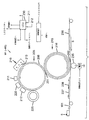
次に、付属の図面を参照しながら説明する。図1および図2は、5色(pentachrome)画像を印刷するのに適した一般的な静電記録式プリントエンジンまたは印刷装置の一部を模式的に示す側面図である。本発明の一実施形態は、直列に並べられた5組の単色画像生成/印刷ステーションまたはモジュールを有する電子写真エンジンを利用した印刷に関するが、本発明は、5つ前後の数のステーションを組み合わせて、単一の受像部材上にトナーを付着させてもよいこと、またはこのようなステーションは、他の一般的な静電記録式書き込み装置または印刷装置を含んでもよいことを想定したものである。 Next, a description will be given with reference to the attached drawings. 1 and 2 are side views schematically showing a part of a general electrostatic recording print engine or printing apparatus suitable for printing a pentachrome image. While one embodiment of the present invention relates to printing utilizing an electrophotographic engine having five sets of monochromatic image generation / printing stations or modules arranged in series, the present invention combines any number of about five stations. It is envisioned that toner may be deposited on a single image receiving member, or such a station may include other common electrostatic recording writing or printing devices.
静電記録式印刷装置100は、直列に配設された複数の静電複写画像形成印刷モジュールM1,M2,M3,M4、およびM5を有する。追加のモジュールを設けることもできる。各印刷モジュールは、連続してモジュール間を移動する受像部材に転写する単色のトナー画像を生成する。各受像部材には、5つのモジュールを通る単一の工程で、最大で5つの単色トナー画像が、前記受像部材と位置合わせされた状態で転写されて、5色の画像が形成される。本明細書では、5色という用語は、受像部材に形成された画像において、受像部材上に他の色を形成するために、5つの色のサブセットの組み合わせが受像部材上の各種の位置において結合されること、および5つの色すべてが、サブセットのうちの少なくとも一部にプロセスカラーを形成することに寄与し、そのサブセットにおいて、5つの各色は、受像部材上の特定の場所において一つ以上の他の色と組み合わされて、その場所で組み合わされる特定の色のトナーとは異なる色を形成できることを含意するものである。
The electrostatic
特定の実施形態において、印刷モジュールM1は、黒色(K)トナーの色分解画像を形成し、M2は、黄色(Y)トナーの色分解画像を形成し、M3は、マゼンタ(M)トナーの色分解画像を形成し、M4はシアン(C)トナーの色分解画像を形成する。印刷モジュール5は、赤色、青色、緑色、または他の第5の色の分解画像を形成できる。4原色のシアン、マゼンタ、黄、および黒は、色の代表的なスペクトルを形成するように、そのサブセットの各種の組み合わせで混合することができ、使用する材料および色の形成に用いられる処理に応じて異なる個別の色域または範囲を有する。ただし、静電記録式印刷装置では、5番目の色を追加して色域を改善することができる。色域への追加に加え、5番目の色は、商標ロゴの作成用などの特殊な色のトナー画像として、または画像を保護するための透明トナーとして利用することもできる。
In a particular embodiment, the printing module M1 forms a color separation image of black (K) toner, M2 forms a color separation image of yellow (Y) toner, and M3 is the color of magenta (M) toner. A separation image is formed, and M4 forms a color separation image of cyan (C) toner. The
受像部材(図2に示すRn〜R(nー6))は、給紙ユニット(図示せず)から送り出されると、図2にRとして示した方向で印刷モジュールM1〜M5を通って搬送される。受像部材は、ローラ102,103の周りに巻かれて駆動されるエンドレス搬送ウェブ101に密着される(たとえば、連結式コロナタックダウン(tack-down)荷電器124,125を介して電気的に密着されると好ましい)。各印刷モジュールM1〜M5は、同様に光導電性画像形成ローラ、中間転写部材ローラ、および転写バックアップローラを含む。したがって、印刷モジュールM1において、光導電画像形成ローラPC1(111)上に黒色トナー分解画像を形成することができ、この黒色トナー分解画像を中間転写部材ローラITM1(112)に転写し、更に、転写ステーションを通過する受像部材に前記画像を再び転写することができる。この転写ステーションが含むITM1は、転写バックアップローラTR1(113)と共に加圧ニップを形成する。同様に、印刷モジュールM2,M3,M4,M5は、PC2,ITM2,TR2(121,122,123)、PC3,ITM3,TR3(131,132,133)、PC4,ITM4,TR4(141,142,143)、PC5,ITM5,TR5(151,152,153)をそれぞれ含む。供給部から到着する受像部材Rnは、ローラ102の上を通っている状態で図示されており、次に第1印刷モジュールM1の転写ステーションに進入するが、その転写ステーションには、先行する受像部材R(n-1)が示されている。同様に、受像部材R(n-2),R(n-3),R(n-4)、およびR(n-5)は、それぞれ印刷モジュールM2,M3,M4、およびM5を通って移動している状態で図示されている。受像部材R(n-6)上に形成された未融着画像は、任意の周知の構成を有する融着アセンブリ60(図1に記載)などの定着器に向かって移動している状態で図示されている。
When the image receiving member (R n to R (n −6 ) shown in FIG. 2) is fed from a paper feeding unit (not shown), it is conveyed through the printing modules M1 to M5 in the direction shown as R in FIG. Is done. The image receiving member is in intimate contact with the
電源装置105は、転写バックアップローラTR1,TR2,TR3,TR4、およびTR5にそれぞれ個別の転写電流を供給する。論理制御装置230(図1)は、一つ以上のコンピュータを含み、電子写真式印刷装置100に対応付けられた各種のセンサからの信号に応答して、個々の構成要素にタイミングおよび制御信号を供給することで、十分に理解されている既知の使用内容に応じた各種構成要素の制御と、装置のプロセス制御パラメータとを提供する。通常は、搬送ウェブ101のための洗浄ステーション101aも設けられており、搬送ウェブ101を連続して再利用できるようになっている。
The
図3を参照すると、代表的な転写モジュール(たとえば、M1〜M5のうちのM1)が示されている。図において、静電記録式印刷装置100の各印刷モジュールは、一つ以上の多層画像または形状を生成する複数の静電記録式画像形成サブシステムを含む。各印刷モジュールには、光導電性画像形成部材(画像形成円筒部205の形式で図示)の表面206を均一かつ静電的に帯電させる一次帯電サブシステム210が含まれている。露光サブシステム220が設けられており、そこで光導電性画像形成部材を露光することによって画像全体で静電荷を均一に調整して、各層の多層(分離)静電潜像を形成する。現像ステーションサブシステム225は、画像全体に露光された導電性画像形成部材を現像する役割を担う。中間転写部材215が設けられており、そこで導電性画像形成部材から転写ニップ201を介して中間転写部材215の表面216に各層の(分離)画像を転写し、更にその画像を、中間転写部材215から受像部材(受像部材236は、転写ニップに進入する前の状態で示され、受像部材237は、多層(分離)画像が転写された後の状態で示されている)に転写する。この受像部材は、その上部に、複合画像を形成するために重畳される各(分離)画像238を受け取る。
Referring to FIG. 3, a representative transfer module (eg, M1 of M1-M5) is shown. In the figure, each printing module of the electrostatic
位置合わせされて重ねられた各(分離)多層画像の転写後に、受像部材は、各印刷モジュールM1〜M5から一つずつ、領域109を超えて融着アセンブリまで進められ、そこで、任意構成として、受像部材に多層トナー画像が融着されて、プリントとも呼ばれる受像製品に構成される。領域109には、センサ104およびエネルギ供給源110が設けられてもよい。この構成は、位置合わせ参照312、およびトナーの各層を付着させるときに利用される他の参照と組み合わせて利用することができ、トナーの各層は、位置合わせパターンなど、一つ以上の位置合わせ参照を基準に配置される。
After transfer of each aligned (separated) multi-layer image, the image receiving member is advanced one by one from each printing module M1-M5, beyond the
本発明の装置は、一つ以上のステーションにおいて、いずれの着色も為されていない透明トナーを利用する。この透明トナーは、前述の着色トナーとは異なるものであり、前述したものより大きい粒子サイズであってよい。本発明の装置によって生成される多層(分離)画像は、表示物である必要はなく、一つ以上の層を有する透明トナーで全体が形成されて示される。これに代えて、画像238は、着色トナーであってもよく、後で詳細に説明するように、透明トナーまたは着色トナーを含む他の層が追従する表示物であってもよい。透明トナーの各層は、同一または異なる屈折率を有することができる。他の実施形態は、透明トナーがフィルタとして機能するように、透明トナーの一部またはすべてを薄く色付けまたは被覆するものである。
The apparatus of the present invention utilizes clear toner that is not colored at one or more stations. This transparent toner is different from the above-described colored toner and may have a particle size larger than that described above. The multilayer (separated) image generated by the apparatus of the present invention does not need to be a display object, and is shown as being formed entirely with a transparent toner having one or more layers. Alternatively, the
印刷モジュール200には、印刷装置の主論理制御装置(LCU)230が対応付けられており、この論理制御装置230は、印刷装置に対応付けられた各種のセンサから入力信号を受け取って、印刷モジュールM1〜M5の荷電器210、露光サブシステム220(たとえば、LEDライタ)、および現像ステーション225に制御信号を送信する。各印刷モジュールは、印刷装置の主LCU230に連結される、それぞれ固有の制御装置を含んでもよい。
The
多層トナー(分離)画像が、重畳した関係で各受像部材に転写された後、受像部材は、順次、搬送ウェブ101から外されて、融着アセンブリ60に向けて送られ、そこで、乾燥トナー画像が受像部材に融着または定着される。この構成は、図2に示す5つのモジュールによって表されているが、一つのモジュールのみを含むものであってもよく、望ましい最終的な所定の多次元形状を含む所望の結果を達成するための要件に応じた2つ以上の個数であると好ましい。次に、搬送ウェブは、その両面124,125(図2を参照)を洗浄し、搬送ウェブ101の対向する表面の上の電荷を中性化する電荷を両面124,125に供給することによって、再利用のために再調整される。
After the multi-layer toner (separated) image is transferred to each image receiving member in a superimposed relationship, the image receiving member is sequentially removed from the
静電像は、個別の現像ステーション225で、潜像を坦持する光導電性ドラムにマーキング粒子(トナー)を塗布することによって現像される。各印刷モジュールM1〜M5の個々の現像ステーションは、それぞれの潜像を現像するのに適した個別の電圧で電気的にバイアスされ、この電圧は、単一の電源によって、または個別の電源(図示せず)によって供給することができる。各現像液は、トナーマーキング粒子と、担体粒子とを含む2成分から成る現像液であると好ましく、前記粒子は磁気を帯びることができる。各現像ステーションは、トナーマーキング粒子の特定の層を有し、このトナーマーキング粒子は該当する層にそれぞれ個別に対応付けられている。したがって、5つの各モジュールは、それぞれの光導電性ドラム上に、異なる層の画像を形成する。下記で更に説明するように、着色(すなわち、カラー)トナーの現像ステーションは、一つ以上の非着色(すなわち、透明な)現像液ステーションと置き換えられてもよく、着色トナーを付着させる他の印刷モジュールと同様に動作することができる。透明トナー印刷モジュールの現像ステーションは、それぞれそのステーションに対応付けられたトナー粒子を有し、このトナー粒子は、トナー結合剤の中に着色粒子が含まれていないことを除き、他の現像ステーションのカラーマーキング粒子と同様である。
The electrostatic image is developed at
更に図1を参照すると、搬送ベルト101は、トナー画像を坦持する受像部材を、任意構成の融着または定着アセンブリ60まで送り、そこで、熱または圧力を印加することによって個々の受像部材にトナー粒子を定着させる。具体的には、融着アセンブリ60は、加熱された融着ローラ62および対向する加圧ローラ64を含み、これらのローラはその間に融着ニップを形成する。融着アセンブリ60は、たとえば、シリコンオイルなどの剥離液を融着ローラ62に塗布する、全体に68として示される剥離液塗布サブステーションも含む。融着された画像を坦持する受像部材、すなわちプリントは、融着アセンブリ60から順次、リモートの出力トレイに向かう経路に送られるか、または、画像形成装置に戻されて、受像部材の裏側に画像が形成される(両面印刷される)。
Still referring to FIG. 1, the
プリントの供給業者および顧客は同様に、静電記録式に形成されたプリントの用途を拡張して、多次元形状、特に、プリントの表面を通る光の伝達を実現する単独または複数の形状を包含させる方式に着眼している。このことは、複数の層状画像を印刷する際に、後述する印刷画像との緊密な位置合わせに利用することができ、この位置合わせは、複数のスポットに立ち止まる観察者によって観察されたときに、前記複数の層状画像に所望の効果を形成するために用いられる。多層形状は、たとえば、光を送ることや他の目的に対応する小型レンズ状の形状であり得る。浮き出し画像の一つのタイプは、小型レンズの配列が、その配列と同一の方式で分割された可視画像に重畳するレンチキュラ(lenticular)画像である。一般に、この画像は、ストライプ状の小型レンズに対応したストライプに分割される。ストライプの各セットがそれぞれ僅かに異なることで見掛け上の動き、または見かけの奥行きを提供する。レンチキュラ画像には、小型レンズのシートと画像プリントとを組み立てることが困難であるという欠点がある。見当合わせは、位置合わせ参照を利用して提供される。 Print suppliers and customers alike extend the use of electrostatographically formed prints to include multi-dimensional shapes, especially one or more shapes that allow the transmission of light through the print surface We are focusing on the method to make it. This can be used for close alignment with a print image, which will be described later, when printing a plurality of layered images, and when this alignment is observed by an observer who stops at a plurality of spots, It is used to form a desired effect on the plurality of layered images. The multi-layer shape can be, for example, a small lens-like shape for sending light or other purposes. One type of raised image is a lenticular image in which an array of small lenses is superimposed on a visible image divided in the same manner as the array. Generally, this image is divided into stripes corresponding to stripe-shaped small lenses. Each set of stripes is slightly different to provide apparent movement, or apparent depth. Lenticular images have the disadvantage that it is difficult to assemble a lenslet sheet and an image print. Registration is provided using alignment references.
位置合わせ参照は、参照パターン150で、これは単独のマークであっても、または所定の配置のマークのパターンもしくは集合であってもよく、本明細書では参照パターンと記す。特定の実施形態において、参照パターンは、レンチキュラ画像、または印刷された他の二次元画像である。参照パターンには、印刷画像と、一つ以上の位置合わせマークとを組み合わせることができる。参照パターンの他に、または参照パターンと同一の空間に印刷画像も設けることができる。本明細書で説明する実施形態において、位置合わせパターンは、完成した出力製品またはプリントの一部である。これに代わる構成として、位置合わせパターンは、完成した出力プリントとは別に配置される。 The alignment reference is a reference pattern 150, which may be a single mark or a pattern or set of marks in a predetermined arrangement, referred to herein as a reference pattern. In certain embodiments, the reference pattern is a lenticular image or other printed two-dimensional image. The reference pattern can be combined with a printed image and one or more alignment marks. In addition to the reference pattern, a print image can be provided in the same space as the reference pattern. In the embodiments described herein, the alignment pattern is part of a finished output product or print. As an alternative configuration, the alignment pattern is arranged separately from the completed output print.
参照パターンは、他のプリンタ手法など、任意の便利な手段で印刷できるが、受像部材には、本発明の方法に適合しなければならないという制約がある。位置合わせパターンも、他のトナー層が配置される方式と同じ方式で、トナーの第1の層として設けることができる。位置合わせパターンは、文字もしくは番号などの表示物、図、図もしくは表示物内のマーク、または隆起したプリントのパターンであってよい。位置合わせパターンも、赤外線、紫外線、化学的に検出可能な表示物、またはすかし模様など、裸眼では不可視のものに構成できる。位置合わせパターンは、たとえば、受像体の2か所のコーナーなどの物理的な特徴であってもよい。後述するように、カラー層と共にトナーの透明層を利用する場合は、透明な隆起プリントも、色の属性に基づいて位置合わせされてよい。 The reference pattern can be printed by any convenient means, such as other printer techniques, with the limitation that the image receiving member must be compatible with the method of the present invention. The alignment pattern can also be provided as the first toner layer in the same manner as other toner layers are arranged. The alignment pattern may be a display such as letters or numbers, a figure, a mark in the figure or display, or a pattern of raised prints. The alignment pattern can also be made invisible to the naked eye, such as infrared, ultraviolet, chemically detectable display, or watermark. The alignment pattern may be a physical feature such as two corners of the receiver. As will be described later, when a transparent layer of toner is utilized along with the color layer, the transparent raised print may also be aligned based on the color attributes.
一実施形態において、図3および図4に示すように、すべての層は、最終的な所定の多次元形状Sを形成する同一または異なる屈折率の透明トナーを有し、受像体上にトナー画像を形成する静電複写式印刷装置100を用いて作製される。この装置は、画像形成部材205と、所定の粒子特性を有する所定サイズのマーキング粒子を利用して、2つ以上のトナーの層を付着させる現像ステーション225とを含む。前述の粒子特性は、ここでは、透明トナーに関して「レンズ形状決定要因」250として示すもので、図4に示す方法によって所定の多次元形状を形成するために用いられる。透明、または後述するような透明な着色トナーの複数の層は、いくつかの方法で取得することができ、この方法は、複数のステーション配列と、複数のステーションおよび互いに位置合わせされてこれらのステーションを通る複数のパスと、Kステーションの置き換えなど、一つ以上の着色ステーションを透明ステーションに置き換えることとのうちの少なくともいずれかを含む。印刷方法は、シート毎に、または一つのシート内など、領域によって異なるものであってよい。たとえば、用紙または受像体の指定領域内のみにレンズを配置する機能は、後述するように、同一シート上の2D画像と同時に3D画像を形成する能力を提供する。
In one embodiment, as shown in FIGS. 3 and 4, all layers have transparent toners of the same or different refractive index that form the final predetermined multidimensional shape S, and a toner image on the receiver. It is manufactured using an
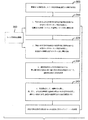
特定の実施形態において、受像体上に隆起した多次元トナー形状の静電記録式印刷を行う方法254は、LCUからの情報に基づいて、位置合わせ参照を基準にトナーの第1層を付着させるステップ256を含み、この付着は、各層、この場合は、所定の多次元形状の第1部分または第1層である層を形成するための指定の「レンズ形状決定要因」を用いて所定のサイズに設定されたマーキング粒子を使用して行われる。次のステップ258において、所定の多次元形状の第2部分または第2層の形成に必要な指定のレンズ形状決定要因を有する所定サイズのマーキング粒子を利用して、位置合わせパターンを基準にトナーの第2層が付着される。3番目のステップ260において、第1層の多次元形状は、最終的な多次元形状を形成するように、第2層の多次元形状に対して位置合わせされる。ステップ1〜4は、264において、所定の多次元形状252を形成するために必要な分だけ繰り返すことができる。
In certain embodiments, a
任意構成として、最終的な所定の多次元形状は、262において、融着中と同様に、熱、圧力、または化学物質を用いて処理されてもよく、これにより、最終的な所定の多次元形状を調整して、望ましい所定の多次元形状または所望の形状特性を付与できる。また、図4に示すように、第1層の多次元形状は、260において、第2層の多次元形状と位置合わせされるが、これは、最終的な多次元形状252を生成するために必要な処理である。コントローラとも呼ばれる論理制御装置230は、多次元形状Sを形成する各層の塗布を制御し、最終的な所定の多次元形状を処理する融着アセンブリ60などの処理装置と協調して最終的な所定の多次元形状を付与する。
Optionally, the final predetermined multidimensional shape may be processed at 262 using heat, pressure, or chemicals, as during fusion, thereby providing the final predetermined multidimensional shape. The shape can be adjusted to provide the desired predetermined multidimensional shape or desired shape characteristics. Also, as shown in FIG. 4, the multi-dimensional shape of the first layer is aligned with the multi-dimensional shape of the second layer at 260 to produce the final multi-dimensional shape 252. Necessary processing. The
図3に示す論理制御装置(LCU)230は、ルックアップテーブルと、LCU230で実行できる制御ソフトウェアとを内蔵するマイクロプロセッサを含む。制御ソフトウェアは、好ましくは、LCU230に関連付けられたメモリに格納される。融着アセンブリに関連付けられたセンサは、該当する信号をLCU230に提供する。このセンサに応答して、LCU230は、融着ニップ66内の熱もしくは圧力、またはその両方を調整するコマンドおよび制御信号を出力し、そうでなければ概して、画像形成基板に関する融着アセンブリ60の動作パラメータの正規化および最適化の少なくともいずれかを行う。
The logical control unit (LCU) 230 shown in FIG. 3 includes a microprocessor that contains a lookup table and control software that can be executed by the
印刷装置100によって書き込まれる画像データは、ラスタ画像プロセッサ(RIP)で処理されてもよく、このプロセッサは、層分離スクリーンまたは色分離スクリーンの生成装置を一つ以上含むことができる。透明層と着色層の両方が積層された画像の場合、RIPの出力は、フレームバッファまたはラインバッファ内に保存されて、たとえば、K,Y,M,C,L(それぞれ黒、黄色、マゼンタ、シアン、透明の略号である)用、またはこれに代わる複数の透明層L1,L2,L3,L4,L5用の各LEDライタに、分離印刷データが送信される。RIPおよび分離スクリーン生成装置の少なくとも一方は、印刷装置の一部であっても、または印刷装置からリモートの装置であってもよい。RIPによって処理される画像データは、カラースキャナなどの多層文書スキャナもしくはデジタルカメラから取得されるか、コンピュータによって生成されるか、または、メモリもしくはネットワークから生成されてよく、このメモリもしくはネットワークは、通常、プリンタで適切に描画されるように、ハーフトーン画像データとして再処理する必要がある連続画像を表す画像データを含んでいる。RIPは、最終プリント上に所望の最終形状を得るために、層の補正などを含む画像処理工程を実行することができる。画像データは、色の分離と同様に各層に分離されて、所望のスクリーン角度およびスクリーン線数を含むマトリクスを用いて、各色の網点画像データに変換される。RIPは、適切にプログラムされたコンピュータおよび論理装置の少なくとも一方であってよく、保存または生成されたマトリクスおよびテンプレートを用いて分離された画像データを処理して、印刷に適したハーフトーン情報の形式で描画される画像データを形成するように構成される。
Image data written by the
本発明によれば、所望の特定の輪郭または形状Sは、静電記録技術によって印刷することができ、この技術は、所定のサイズ特性を有するマーキング粒子を利用して、受像部材R上に、求められている最終的な所定の隆起多次元形状を形成するステップを含む。このサイズ特性は、特定のサイズt1、サイズ分布、ならびに集積性および多孔性などの他の特性のうちの少なくともいずれかを含むことができる。特定の実施形態において、粒子サイズは、現在利用されている市販のカラートナーの粒子サイズの範囲よりもかなり大きいサイズである。選択されたマーキング粒子は、図5に示すような所定の多次元形状を形成するために利用される。これは、前述した装置100のような静電記録式複写装置を用いて、受像部材Rn(図6〜7を参照)上のトナー粒子tの積み重ね高さTを制御することによって実現できる。
According to the invention, the desired specific contour or shape S can be printed by electrostatic recording technology, which utilizes marking particles having a predetermined size characteristic on the image receiving member R, Forming the final desired raised multidimensional shape being sought. This size characteristic can include a particular size t 1 , a size distribution, and / or other characteristics such as accumulation and porosity. In certain embodiments, the particle size is significantly larger than the particle size range of currently available commercial color toners. The selected marking particles are used to form a predetermined multidimensional shape as shown in FIG. This can be realized by controlling the stacking height T of the toner particles t on the image receiving member Rn (see FIGS. 6 to 7) using an electrostatic recording copying apparatus such as the
一つの静電記録モジュールにおいて、サイズが異なる粒子を含むことで粒子の集積性が高く成り得る、異なるサイズのトナー粒子集合を用いて、隆起多次元トナー形状を印刷する場合は、一つ以上の静電記録プロセスの設定値または動作アルゴリズムを変更して、結果的に得られるプリントの性能、信頼性、および画像品質の少なくともいずれかを最適化すると有利である。前述の設定値は、最終形状の高さと、形状と、他の特徴とを制御するために利用できる現像電位および他の転写プロセスの設定値を含む。異なるサイズのトナー粒子集合の例は、離散的に(discreet)分断された比較的大きいピークが2つ以上ある連続したサイズ分布を有するトナーである。このような集合は、適切な複数のサイズ、すなわち適切な範囲の粒子サイズを有する2種類以上のトナーを混合することによって得られる。このサイズ変数は、粒子サイズ、粒子分布、および複数のピークを有する分布によって表される粒子サイズの多重分布の場合のような複数のサイズを含む。これらは標準の集積性を有することになる。集積性を変更して、所望の効果を拡張することができ、必要に応じて最適な集積性を決定できる。静電記録式プロセスの設定値(動作アルゴリズム)の値は、隆起多次元トナー形状を印刷するときに、所定の値を入れ替えるように、静電記録式印刷装置において制御することができ、この値の例は、たとえば、融着温度、融着ニップ幅、融着ニップ圧、光導電性部材上の画像形成電圧、トナー粒子現像電圧、転写電圧、および転写電流である。隆起多次元トナー形状のプリントを生成する静電記録式装置において、動作の特殊モードを設定することができ、このモードでは、隆起多次元トナー形状を印刷するときに、所定の設定値(制御パラメータまたはアルゴリズムとして実施される設定値)が利用される。すなわち、静電記録式印刷装置が、隆起しない多次元トナー形状の画像を印刷するときには、設定値/制御パラメータの第1セットが利用される。そして、静電記録式印刷装置が、隆起した多次元トナー形状の画像を印刷するモードに変わると、設定値/制御パラメータの第2セットが利用される。一つ以上の特定のトナーに用いる設定値は、経験則から決定することができる。 When printing a raised multi-dimensional toner shape using a set of toner particles of different sizes, which can increase particle accumulation by including particles of different sizes in one electrostatic recording module, one or more It may be advantageous to change settings or operating algorithms of the electrostatic recording process to optimize the resulting print performance, reliability, and / or image quality. The setpoints described above include development potentials and other transfer process setpoints that can be used to control the height of the final shape, shape, and other features. An example of a collection of toner particles of different sizes is a toner having a continuous size distribution with two or more relatively large peaks that are discretely divided. Such a collection is obtained by mixing two or more types of toners having an appropriate plurality of sizes, that is, an appropriate range of particle sizes. This size variable includes multiple sizes, such as in the case of multiple distributions of particle sizes represented by particle size, particle distribution, and distributions having multiple peaks. These will have standard integration. The integration can be changed to extend the desired effect and the optimal integration can be determined as needed. The value of the electrostatic recording process setting value (operation algorithm) can be controlled in the electrostatic recording printing apparatus so as to replace a predetermined value when printing a raised multidimensional toner shape. Examples are fusing temperature, fusing nip width, fusing nip pressure, image forming voltage on the photoconductive member, toner particle development voltage, transfer voltage, and transfer current. A special mode of operation can be set in an electrostatic recording device that generates a raised multi-dimensional toner shape print. In this mode, when printing a raised multi-dimensional toner shape, a predetermined set value (control parameter) is set. Alternatively, a setting value implemented as an algorithm) is used. That is, when the electrostatic recording printing apparatus prints an image having a multidimensional toner shape that does not protrude, the first set of setting values / control parameters is used. When the electrostatic recording printer changes to a mode for printing a raised multidimensional toner-shaped image, the second set of set values / control parameters is used. The set values used for one or more specific toners can be determined from empirical rules.
最終の多次元形状が、曲率半径を含む特定の高さと輪郭、および屈折率を持つことによって、その形状から各種のレンズ形状を含む範囲の形状の印刷物が得られる。粒子の集積性をより高めることになり得る異なるサイズを持つ粒子を含む、異なるサイズのトナー粒子の集合を制御することで、前述した形状を得る。 When the final multidimensional shape has a specific height and contour including a radius of curvature, and a refractive index, a printed matter having a shape in a range including various lens shapes can be obtained from the shape. The shape described above is obtained by controlling the collection of toner particles of different sizes, including particles of different sizes, which can further enhance particle accumulation.
「レンズ形状決定要因」のいくつかは、マーキング粒子の特定のサイズ分布を含む。付加的な「レンズ形状決定要因」としては、耐久性、透明度、色、形態、表面粗さ、平滑性、色の鮮明度、および屈折率が挙げられる。また、他の所定の粒子特性は、トナーの粘度、色、密度、表面張力、融点、ならびに融着ローラおよび加圧ローラを利用することを含む仕上げ方法のうちの一つ以上を含む「レンズ形状決定要因」であってよい。 Some of the “lens shape determinants” include a specific size distribution of marking particles. Additional “lens shape determining factors” include durability, transparency, color, morphology, surface roughness, smoothness, color sharpness, and refractive index. Other predetermined particle characteristics also include one or more of toner viscosity, color, density, surface tension, melting point, and a finishing method including utilizing a fuser roller and a pressure roller. It may be a determinant.
一実施形態において最終の所定形状の形成に用いられるトナーは、スチレン(スチレンブチルアクリレート)型またはポリエステル型のトナー結合剤であってよい。これらの重合体がトナー樹脂として用いられた場合の一般的な屈折率は、1.53から約1.60の範囲である。これは、ポリエステルトナー結合剤およびスチレン(スチレンブチルアクリレート)トナーについての典型的な屈折率測定値である。通常、ポリエステルは約1.54程度であり、スチレン樹脂は1.59である。この測定が(当業者に周知の方法により)行われた時の条件は、室温、および590nmである。他の同様の材料も利用できることは、当業者であれば理解されるであろう。このような材料は、PVCに加え、ポリエステル型およびスチレンアクリレート型両方の熱可塑性樹脂を含み、特に投射組立などの高温の用途においては、ポリカーボネートも含む。一例として、イーストマンケミカル(Eastman Chemical)社のポリエステルを基材とした樹脂シートであるLenstar(登録商標)が挙げられ、これはレンチキュラ市場用として特別に設計されたものである。また、熱硬化性プラスチックも利用でき、イスラエル工科大学(Israel Institute Technology)において、市販の不飽和ポリエステル樹脂からPVAI安定化懸濁液重合系内で調製された熱硬化性ポリエステルビードなどがある。 In one embodiment, the toner used to form the final predetermined shape may be a styrene (styrene butyl acrylate) type or polyester type toner binder. The typical refractive index when these polymers are used as toner resin is in the range of 1.53 to about 1.60. This is a typical refractive index measurement for polyester toner binder and styrene (styrene butyl acrylate) toner. Usually, polyester is about 1.54 and styrene resin is 1.59. The conditions when this measurement was made (by methods well known to those skilled in the art) are room temperature and 590 nm. One skilled in the art will appreciate that other similar materials can be utilized. Such materials include, in addition to PVC, thermoplastics of both polyester and styrene acrylate types, especially polycarbonates in high temperature applications such as projection assembly. An example is Lenstar®, a resin sheet based on Eastman Chemical's polyester, which is specially designed for the lenticular market. Thermoset plastics are also available, such as thermoset polyester beads prepared in Israeli Institute of Technology (Israel Institute Technology) from commercially available unsaturated polyester resins in a PVAI stabilized suspension polymerization system.
最終の所定形状の形成に用いられるトナーは、サイズ分布の影響を受けるため、正確に制御されたサイズおよび形状であることが求められる。このことは、トナー粒子を粉砕して処理することで、各種の合成サイズを得ることによって実現できる。この方法は、サイズが小さく、より緊密なサイズ分布である粒子については実行することが困難であるが、これは、分離しなければならない多数の微粉が生成されるためである。このような処理は、分散が貧弱になるか、もしくは費用が高くかかりながらも制御の不正確なプロセスが行われるかのいずれか、またはその両方の結果に至る。これに代わる方法は、シリコンなどの粒子を安定化させることによってサイズを制御できる限定的合一(limited coalescence)技法および気化による限定的合一技法の両方またはそのいずれかを利用することである。以下、このような粒子のことを化学的に調製された固体インク(CDI)と呼ぶ。これらの限定的合一技法では、一般に、実質的に均一なサイズと均一なサイズ分布とを有するトナー粒子が形成されることになるため、この限定的合一技法のいくつかは、静電トナー粒子の調製に関する特許に記載されている。トナーの調製に採用される代表的な限定的合一プロセスは、米国特許第4,833,060号明細書および第4,965,131号明細書に記載されている。 Since the toner used for forming the final predetermined shape is affected by the size distribution, it is required to have a precisely controlled size and shape. This can be achieved by obtaining various synthetic sizes by grinding and processing the toner particles. This method is difficult to perform for particles that are small in size and have a tighter size distribution, because it produces a large number of fines that must be separated. Such processing can result in either poor dispersion and / or costly but inaccurate control processes, or both. An alternative method is to use limited coalescence techniques that can control size by stabilizing particles such as silicon and / or limited coalescence techniques by vaporization. Hereinafter, such particles are referred to as chemically prepared solid ink (CDI). Because these limited coalescence techniques generally result in the formation of toner particles having a substantially uniform size and uniform size distribution, some of these limited coalescence techniques are electrostatic toners. It is described in patents relating to the preparation of particles. Typical limited coalescence processes employed in toner preparation are described in US Pat. Nos. 4,833,060 and 4,965,131.
前述した限定的合一技法において、電荷制御剤および着色剤などのトナー添加剤を適切に選択すれば、水性有機中間相の存在を活用することによって、トナー粒子の表面粗さを制御できる。この目的で採用される、本質的に高い界面活性または親水性を有するトナー添加剤は、トナー粒子の表面にも存在し得る点を考慮することは重要である。良好な結果を得るための重要な粒子要因および環境要因は、トナー粒子の電荷/質量比(低過ぎてはならない)、表面粗さ、熱転写の不足、静電転写の不足、少ない着色剤所要量、ならびにトナーまたは用紙に影響を与える温度、湿度、化学物質、および放射線などの環境作用を含む。サイズ分布に対してこれらの作用が存在するため、環境感度を制御するために、トナー粒子は、通常の動作範囲に制御および維持されなければならない。 In the limited coalescence technique described above, the surface roughness of the toner particles can be controlled by taking advantage of the presence of the aqueous organic mesophase if the toner additives such as charge control agents and colorants are appropriately selected. It is important to consider that the toner additives that are employed for this purpose and that have essentially high surface activity or hydrophilicity may also be present on the surface of the toner particles. Important particle and environmental factors for good results are toner particle charge / mass ratio (must not be too low), surface roughness, thermal transfer deficiency, electrostatic transfer deficiency, low colorant requirements And environmental effects such as temperature, humidity, chemicals, and radiation that affect toner or paper. Because of these effects on the size distribution, the toner particles must be controlled and maintained in the normal operating range to control environmental sensitivity.
また、このトナーは、150〜500、通常は345の引張弾性率(103psi)と、300〜500、通常は340の曲げ弾性率(103psi)と、M70〜M72の(ロックウェル)硬度、68〜70(10-6)/度摂氏の熱膨張、1.2の比重、露光時の若干の緩慢な黄変も有することは、J.H.デュボイス(DuBois)およびF.W.ジョン(John)編纂の「Plastics(プラスチック)」第5版、ヴァン ノーストランド アンド ラインホルド(Van Norstrand and Reinhold)出版、1974年(522ページ)に記載されている。 The toner also has a tensile modulus (10 3 psi) of 150 to 500, usually 345, a flexural modulus (10 3 psi) of 300 to 500, usually 340, and (Rockwell) of M70 to M72. It also has a hardness of 68-70 (10 −6 ) / degree Celsius, a specific gravity of 1.2, and a slight slow yellowing upon exposure. H. DuBois and F.M. W. “Plastics”, 5th edition, edited by John, published in Van Norstrand and Reinhold, 1974 (page 522).
この特定の実施形態において、さまざまな特性が、このトナーを利用できる適切なトナーとして構成する。いずれの接触加熱定着においても、特定の最終所望形状を実現するためには、融着速度、適用される駐留時間および関連圧力も重要である。接触加熱定着は、処理時間をより高速にする場合に必要になり得る。各種の仕上げ方法には、熱、圧力、化学物質に加え、IRおよびUVによる接触および非接触の両方の処理がある。記載したトナーは、通常、摂氏50〜300度の間であり得る溶融範囲を有する。表面張力、粗さ、および粘度は、より適切な転写を行うために、円形ではなく球形状を生じるものでなければならない。表面の輪郭および粗さは、Federal5000「Surf Analyzer(表面分析装置)」を用いて測定することができ、ミクロンなどの標準の単位で測定される。前述したように、トナー粒子のサイズも重要であり、より大きい粒子では、通常、空気包含量が少ないことから、より大きい粒子からは、所望の高さおよび形状が得られるのみならず、より透明な形状も得られる。色濃度は、よく知られているように、グレタグマクベス(Gretag−Macbeth)社製の色彩計において、標準CIE検査で測定されてL*a*b*単位で表される。トナーの粘度は、粘度を測定する計器であるムーニー粘度計で測定され、粘度がより高いと、形状がよりよく維持されて、より高い高さが得られる。また、粘度の高いトナーでは、より長期に亘って保持される形状が得られる。 In this particular embodiment, various characteristics constitute this toner as a suitable toner that can be used. In any contact heat fixing, the fusing speed, applied dwell time and associated pressure are also important in order to achieve a specific final desired shape. Contact heat fixing may be required for faster processing times. Various finishing methods include both contact and non-contact treatment with IR and UV in addition to heat, pressure, and chemicals. The toners described have a melting range that can typically be between 50 and 300 degrees Celsius. Surface tension, roughness, and viscosity must produce a spherical shape rather than a circle in order to achieve a more appropriate transfer. Surface contour and roughness can be measured using a Federal 5000 “Surf Analyzer” and is measured in standard units such as microns. As noted above, the size of the toner particles is also important, and larger particles usually have less air coverage, so larger particles not only provide the desired height and shape, but are also more transparent Can be obtained. As is well known, the color density is measured by a standard CIE test and expressed in L * a * b * units in a color meter manufactured by Gretag-Macbeth. The viscosity of the toner is measured with a Mooney viscometer, which is an instrument for measuring the viscosity. A higher viscosity results in better shape maintenance and higher height. In addition, in the case of a toner having a high viscosity, a shape that can be held for a longer period of time can be obtained.
融点は、前述したガラス転移温度(Tg)ほどには重要でないことが多い。その範囲は、摂氏約50〜100度で、多くの場合、摂氏約60度程度である。UVおよびIR照射時の色もしくは透明度、またはその両方の耐久性は、時間の経過に伴う透明度の喪失として判断することができる。この喪失程度が低いほど、より適切な結果になる。透明度、すなわち曇り度が低いことは、透過型または反射型の光学素子にとって重要であり、この場合、透明度は指標で、曇り度は、高率の透過光の測定値である。 The melting point is often not as important as the glass transition temperature (Tg) described above. The range is about 50 to 100 degrees Celsius, and in many cases about 60 degrees Celsius. The durability of the color and / or transparency during UV and IR irradiation, or both, can be judged as the loss of transparency over time. The lower the loss, the more appropriate the result. Low transparency, i.e., low haze, is important for transmissive or reflective optical elements, where transparency is an indicator and haze is a measure of high rate transmitted light.
これらのレンズ形状決定要因は、本明細書に記載されるように、試験室で実験的に割り出すことができ、また、使用中に時間の経過に伴って発展させることもできる。更に、このようなレンズ形状決定要因のライブラリを徐々に構築して、オペレータが、前述したような最終の多次元形状を印刷したいと思うときに利用できるようにしてもよい。 These lens shape determinants can be determined experimentally in a laboratory, as described herein, and can also evolve over time during use. Further, such a library of lens shape determining factors may be gradually constructed so that the operator can use it when he / she wants to print the final multidimensional shape as described above.
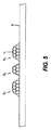
特定の実施形態において、「平坦な」画像の上に隆起多次元トナー形状を作製するための基本的な前提は、最終的な多次元トナー形状は、少なくとも20μmのトナー粒子積み重ね高さTを有することである。積み重ね高さTは、標準の一般的平均である平均高さ加重直径が9μm未満であるトナー粒子t1の層の上に選択的に層を重ねることによって形成でき、この各層は、ここでは、S3形状およびS1形状(図6を参照)として示す一つ以上の形状について、0.4〜0.5mg/cm2の載置被覆率を有する。トナー粒子に関して、トナーのサイズまたは直径は、コールター社(Coulter,Inc.)によって販売されているコールターマルチサイザ(Coulter Multisizer)などの従来の直径測定装置によって測定される平均体積加重直径に換算して定義される。平均体積加重直径は、各トナー粒子の質量に当該トナー粒子と質量及び密度が等しい球状粒子の直径を掛けたものの合計を、全粒子の質量で除したものである。 In certain embodiments, the basic premise for creating a raised multidimensional toner shape on a “flat” image is that the final multidimensional toner shape has a toner particle stack height T of at least 20 μm. That is. The stack height T can be formed by selectively layering a layer of toner particles t 1 with an average height weighted diameter of less than 9 μm, which is a standard general average, each layer here being About one or more shapes shown as S3 shape and S1 shape (refer FIG. 6), it has the mounting coverage of 0.4-0.5 mg / cm < 2 >. For toner particles, the toner size or diameter is converted to an average volume weighted diameter measured by a conventional diameter measuring device such as Coulter Multisizer sold by Coulter, Inc. Defined. The average volume weighted diameter is the sum of the mass of each toner particle multiplied by the diameter of a spherical particle having the same mass and density as the toner particle divided by the mass of all particles.
これに代えて、標準サイズのトナー粒子t1の複数の層は、所望の位置に関して所望の隆起多次元トナー形状になるように、一般的平均である平均体積加重直径が12〜30μmであるより大きいトナー粒子t2の層で選択的に被覆されてもよい(図7を参照)。より大きいトナー粒子は、完全に透明な着色剤で、少なくとも2mg/cm2の載置被覆率を有することが好ましく、ここではS4およびS1形状として示されている。前述したように、本明細書においてS1およびS2形状として示されている最終的な所定の隆起多次元形状Sには、たとえば、前景レンズまたは第1レンズを提供して文書に機密保護特性を付与することや、異なる照明状態かつ多様な角度で見られる多次元画像を提供することなどを含む各種の用途があり得る。図7の側面図により、略放物線状の形状が明瞭に示されており、この放物線状の形状により、その次元の形状は、画像の上に配置されたときに、各種の角度で連続して視認することで動いているように見える。 Instead, the multiple layers of standard size toner particles t 1 have a general average average volume weighted diameter of 12-30 μm so that they have the desired raised multidimensional toner shape for the desired location. It may be selectively coated with a layer of large toner particles t 2 (see FIG. 7). The larger toner particles are preferably completely transparent colorants and preferably have a loading coverage of at least 2 mg / cm 2 , shown here as S 4 and S 1 shapes. As described above, the final predetermined raised multidimensional shape S, shown herein as S 1 and S 2 shapes, may be provided with, for example, a foreground lens or a first lens to provide security features to the document. There may be various applications including providing a multi-dimensional image viewed at various angles with different lighting conditions. The side view of FIG. 7 clearly shows a substantially parabolic shape, and this parabolic shape allows the dimensional shape to be continuous at various angles when placed on the image. It looks like it moves by visual recognition.
各種の層の高さは、所望の隆起多次元トナー形状の作製における一つの係数である。各層が配置された後、高さが読み取られ、トナーについてのレンズ形状決定要因情報に基づいて再計算された残りの高さを使用して、残りの層を配置するときに高さを修正する必要があるかどうか、または熱を抑制した定着ステップなど、代替の仕上げ方法を組み合わせて用いて、代わりの層を塗布する必要があるかどうかが決定される。これに代えて、高さの確認は、所望の隆起多次元トナー形状の実現を補助するために、複数工程方式における各工程の後で行うこともできる。これらの決定は、位置合わせパターンに基づいて最も容易に行うことができるが、必要に応じてランダムに行ってもよい。 The height of the various layers is a factor in the production of the desired raised multidimensional toner shape. After each layer is placed, the height is read and the remaining height recalculated based on lens shape determinant information about the toner is used to correct the height when placing the remaining layers A combination of alternative finishing methods, such as a heat-suppressing fixing step, is used to determine if an alternative layer needs to be applied. Alternatively, height confirmation can be performed after each step in a multi-step process to assist in achieving the desired raised multidimensional toner shape. These determinations can be most easily performed based on the alignment pattern, but may be performed randomly as necessary.
イーストマンコダックに譲渡された米国特許第6,421,522号には、複数の露光装置を有する多色機械において、正確な位置合わせパターン、ひいては正確なトナーの位置が、現在の用途において必要とされる状態で達成されるように位置合わせを設定する方法および装置の一つが記載されている。この特許は、特に、位置合わせ時のトナーの輪郭の作用について検討したものである。制御のために追加して設けられる必要な構成要素は、個々の印刷モジュールの各種の処理要素の周りに組み立てることができる(たとえば、均一な静電荷を測定する計器211、表面206上の非画像領域に形成されることがある補修潜像の補修領域内の露光後の表面電位を測定する計器212など)。静電記録式印刷装置100についての更なる詳細は、イー(Yee S.Ng)他の名前で2006年6月22日に公開された、米国特許出願公開第2006/0133870号に記載されている。
In US Pat. No. 6,421,522 assigned to Eastman Kodak, a multi-color machine having multiple exposure devices requires an accurate alignment pattern and thus an accurate toner position in current applications. One of the methods and apparatus for setting the alignment to be achieved in the described state is described. This patent specifically examines the effect of toner contours during alignment. The necessary components that are additionally provided for control can be assembled around the various processing elements of the individual printing modules (eg,
他の実施形態では、他の自己整合方法を利用して、複数の工程で3D構造を構築する。この方法は次のステップを含む。
(a)4色の画像形成後に、第5ステーションは、化学的に調製された固体インクなど、ガラス転移温度(Tg)の高い透明トナーを利用して、後の工程で内部にレンチキュラ材料が進入できる谷形チャンネルを形成する。たとえば、20〜40μmの高さの1D稜線を、6ピクセル分の間隔(〜258μm)で配置できる。この稜線は、ある程度の幅(2ピクセル程度の幅で、〜86μmから100μm)を持つ。特定の一実施形態において、20〜40μmの化学的に調製された固体インク(CDI)を、非接触加熱融着(放射/せん光など)と組み合わせて利用して稜線を形成することができる。CPDは、イーストマンコダックに譲渡された米国特許第4,833,060号明細書および第4,965,131号明細書に記載されている。
(b)連続した複数の工程において、一つは、Tgが十分に低いCDI材料を配置できるものであってよい(すなわち、100〜150umで、レンズ材料を形成する諧調画像の形成であってもよい)。融着時により低い融着温度を用いれば、稜線材料は融解しないため、Tgの低い材料が下方のカラー画像と整列していない場合であっても、溝のラインが存在するという事実、およびTgの低い溶融したCDIの湿潤性とに起因して、このTgの低い材料は、湿潤性および重力のおかげで溝内に流入して、下方の溝と 整列する三次元のドーム形レンズを形成し、レンチキュラレンズを構成する。特定の一実施形態において、5つのステーションのすべてで、稜線材料よりも低いTgを有するCDIを利用する。
In other embodiments, other self-alignment methods are utilized to build a 3D structure in multiple steps. The method includes the following steps.
(A) After the four-color image is formed, the fifth station uses a transparent toner having a high glass transition temperature (Tg) such as a chemically prepared solid ink, and the lenticular material enters inside in a later process. Form a possible valley channel. For example, 1D ridge lines with a height of 20 to 40 μm can be arranged at intervals of 6 pixels (˜258 μm). This ridgeline has a certain width (about 86 pixels to 100 μm in width of about 2 pixels). In one particular embodiment, 20-40 μm chemically prepared solid ink (CDI) can be utilized in combination with non-contact heat fusing (such as radiation / flash) to form ridges. CPD is described in U.S. Pat. Nos. 4,833,060 and 4,965,131 assigned to Eastman Kodak.
(B) In a plurality of continuous processes, one may be capable of disposing a CDI material having a sufficiently low Tg (that is, even in the formation of a gradation image having a lens material of 100 to 150 μm). Good). The fact that the ridge material does not melt if a lower fusing temperature is used during fusing, the fact that there is a line of grooves even if the low Tg material is not aligned with the underlying color image, and Tg Due to the low melted CDI wettability, this low Tg material flows into the groove due to wettability and gravity to form a three-dimensional dome-shaped lens that aligns with the lower groove. The lenticular lens is configured. In one particular embodiment, all five stations utilize CDI with a lower Tg than the ridge material.
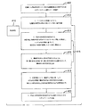
一実施形態において、図8に示すように、受像体の上に隆起多次元トナー形状を静電記録式に印刷する方法300は、所定の多次元形状Sを形成する所定の粒子特性を有する所定サイズのマーキング粒子を利用して、位置合わせ参照312を基準にトナーの第1層を付着させるステップ310と、所定サイズのマーキング粒子を利用して、位置合わせパターンやマークなどの位置合わせ参照を基準にトナーの一つ以上の追加の層を付着させるステップ320と、前記第1層の多次元形状を第2の層の多次元形状に位置合わせして、最終的な多次元形状を形成するステップ330と、追加の処理340とを含む。最終的な所定の多次元形状は、融着中に、熱もしくは圧力、またはその両方を用いて融着するなど、処理および定着されて、最終的な所定の多次元形状に追加の性質または形状特性を付与することができる。
In one embodiment, as shown in FIG. 8, a
所定の粒子特性は、「レンズ形状決定要因」350とも呼ばれ、マーキング粒子の特定のサイズ分布を含む。追加の「レンズ形状決定要因」は、耐久性、透明度、色、形態、表面粗さ、平滑性、色の鮮明度、および屈折率を含む。マーキング粒子の特定のサイズ分布の一つは、第1層についての6〜12ミクロンの体積平均直径、ならびに第2および後続の層についての12〜30ミクロンの体積平均直径を含む。前述したように測定された14および19ミクロンの好ましい定着前の平均粒子サイズは、透明トナーの単一の層を利用して、それぞれ約14および19ミクロンの平均高さで最終的に定着された三次元形状のレンズを生成した。位置合わせされる複数の層を利用して、レンズの高さを100ミクロンまで大きくすることができる。画像上に曲線状の形状および12〜100ミクロンの高さを有する最終形状により、画像は、角度を変えて視認すると動くように見える三次元形状になる。曲線状の形状は、図7にS4として示されるような略放物線状の形状である。 The predetermined particle characteristics, also called “lens shape determinants” 350, include a specific size distribution of marking particles. Additional “lens shape determinants” include durability, transparency, color, morphology, surface roughness, smoothness, color sharpness, and refractive index. One particular size distribution of marking particles includes a volume average diameter of 6-12 microns for the first layer and a volume average diameter of 12-30 microns for the second and subsequent layers. The preferred average particle size before fixing of 14 and 19 microns measured as described above was finally fixed at an average height of about 14 and 19 microns, respectively, utilizing a single layer of clear toner. A three-dimensional lens was generated. Using multiple layers that are aligned, the lens height can be increased to 100 microns. Due to the curved shape on the image and the final shape having a height of 12-100 microns, the image becomes a three-dimensional shape that appears to move when viewed at different angles. The curved shape is a substantially parabolic shape as shown by S4 in FIG.
一実施形態において、所望の隆起多次元トナー形状は、倍率を有する光学素子であるレンズを構成する形状である。倍率付きレンズは、その中を通る光に非ニュートラルな影響を与えるもので、換言すると、光線は、レンズを通過するときに平行な状態が維持されなくなる。レンズの光学倍率は、1/fとして定義されるため、メニスカスレンズはゼロの倍率を有し、他のレンズは、そのレンズが画像を拡大するか、または小さく見せる場合に正または負の倍率を有する。レンズの倍率は、メートルの逆数(m-1)に等しい単位である視度で測定される。 In one embodiment, the desired raised multidimensional toner shape is the shape that constitutes a lens that is an optical element having magnification. A lens with a magnification has a non-neutral effect on the light that passes through it, in other words, the rays do not remain parallel when they pass through the lens. Since the optical magnification of the lens is defined as 1 / f, the meniscus lens has a magnification of zero, and the other lenses have a positive or negative magnification when the lens enlarges or looks smaller. Have. The magnification of a lens is measured in diopter, which is a unit equal to the reciprocal of a meter (m −1 ).
例としては、下記のものおよびその随意的等価物があり、凸レンズ、両凸レンズ、平凸レンズ、凸凹レンズ、凹レンズ、平凹レンズ、両凹レンズ、メニスカスレンズ、フレネルレンズ、各種のプリズム、および他の周知のレンズ形状が挙げられる。これらのレンズ形状は、曲率半径(「R」)、焦点距離(f)、レンズを構成する材料の屈折率(n)、ならびに透明トナーと着色トナーの両方を含み得る厚さ(d)および高さを含む各種の用語によって定義される。 Examples include the following and their optional equivalents: convex lens, biconvex lens, plano-convex lens, convex / concave lens, concave lens, plano-concave lens, biconcave lens, meniscus lens, Fresnel lens, various prisms, and other well-known A lens shape is mentioned. These lens shapes include a radius of curvature (“R”), a focal length (f), a refractive index of the material comprising the lens (n), and a thickness (d) and high that can include both transparent and colored toners. Defined by various terms including
空気中におけるレンズの焦点距離は、レンズ製造業者の数式を用いて次のように計算することができる。 The focal length of the lens in air can be calculated using the lens manufacturer's formula as follows:
[数1]
1/f=(n−1)[1/R1−1/R2+(n−1)d/nR1R2]
上式において、R1は、光源に近い側のレンズ面の曲率半径、R2は、光源から遠い側のレンズ面の曲率半径である。
[Equation 1]
1 / f = (n−1) [1 / R 1 −1 / R 2 + (n−1) d / nR 1 R 2 ]
In the above equation, R 1 is the radius of curvature of the lens surface closer to the light source, and R 2 is the radius of curvature of the lens surface farther from the light source.
代替の構成として、所望の隆起多次元トナー形状が倍率を持たない場合にも、この形状は依然として所望の効果を奏することができ、特定の状況においては、たとえば、当業者に周知の方式において活用されるフレネルレンズと同様に有用なものになり得る。倍率を有する光学素子は、前述したように倍率付きのレンズに位置合わせされる、対応する表示物を用いても、または用いなくても、受像体に適用されたときに有用な追加の特性を有する。 As an alternative, if the desired raised multidimensional toner shape does not have magnification, this shape can still have the desired effect, and in certain situations, for example, utilized in a manner well known to those skilled in the art. It can be as useful as a Fresnel lens. An optical element having a magnification provides additional properties useful when applied to a receiver, with or without a corresponding display, aligned with a lens with magnification as described above. Have.
倍率を持たない光学素子も、表面特性のタイプを表す視覚的または触覚的に有用な多数の結果をもたらし得るため、極めて有利に活用することができる。この例は、水槽内の魚の画像を含み、この場合、魚と水槽の少なくともいずれかを部分的に隆起させて、仮想の「水中」効果をシミュレーションする。他の用途としては、倍率を有する光学素子、または倍率を持たない光学素子のいずれかを含む所定の多次元形状を追加するセキュリティ効果が挙げられる。他の有用な用途は、点字の文字である表示物を、対応する言語の文字と共に、または対応する言語の文字なしで印刷することである。点字の文字を、その言語の文字の近くに位置合わせした状態で印刷すると、目の見える人と見えない人の両方が同時に同じ単語を読めるようになると共に、2つの言語の一方の学習を手助けできるため有用である。2つ以上の言語への光学素子の利用は、両方の言語を同時に見ることができるため、他の言語の学習を支援することにも役立つ。小さい子供たちの教育であっても、文字や楽譜や画像と、文字および他の複合的に関連する学習支援素材との二重または多重に表示可能な組み合わせを用いて拡張することができる。所定の多次元形状は表面に印刷できるため、所定の多次元形状は、その下に存在する受像体ベースから除去することが可能である。 Optical elements that do not have magnification can also be used very advantageously because they can produce a number of visually or tactilely useful results that represent the type of surface property. This example includes an image of a fish in the aquarium, where the fish and / or the aquarium are partially raised to simulate a virtual “underwater” effect. Other applications include a security effect of adding a predetermined multidimensional shape including either an optical element having a magnification or an optical element not having a magnification. Another useful application is to print a display that is braille characters with or without the corresponding language characters. Printing braille characters in close proximity to the characters in that language will allow both visible and invisible people to read the same word at the same time and help them learn one of the two languages It is useful because it can. The use of optical elements for more than one language also helps to learn other languages because both languages can be viewed simultaneously. Even small children's education can be extended with double or multiple displayable combinations of letters, music scores and images with letters and other complex related learning aids. Since the predetermined multidimensional shape can be printed on the surface, the predetermined multidimensional shape can be removed from the underlying receiver base.
これらの形状は、写真、ポスター、LCD表示、プロジェクタ、光導体、および光導波路内の画像と組み合わせて形成することができる。この形状を利用して、視角と、光彩、色ずれ、および3D画像などの他の興味深い効果とについて、光学的に視認可能な画像を形成することができる。 These shapes can be formed in combination with pictures, posters, LCD displays, projectors, light guides, and images in light guides. This shape can be used to form optically visible images for viewing angles and other interesting effects such as glow, color shift, and 3D images.
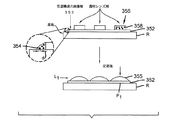
図9に、マーキング粒子の特定のサイズ分布に、第1の層352と、第2の層356とを含む実施形態を示す。この実施形態において、前記第1の層352は、任意構成の画像層353として図示される第1の層に対応したプリンタで取得できる程度で小さい第1体積平均直径「d1」を持つトナー354から形成される一方で、前記第2の層356が、前記第1体積平均直径よりも大きい体積平均直径「d2」(「d2」≧「d1」)を持つトナー358から形成されることで、最終的な所定の多次元形状L1を提供する。好ましい一実施形態において、最終的な所定の多次元形状355は、少なくとも20μmのマーキング粒子積み重ね総高さから形成される。この最終的な所定の多次元形状355は、画像層353を基準に形状が配置されるように、漸増式に第1位置合わせパターンまたはマーク(P1)と位置合わせされる。したがって、たとえば、前記形状が1.6の屈折率を有する曲線状のレンズである場合に、1.0を超える倍率を提供するため、図9に示すように、P1において直接、画像の上に配置された場合、観察者Oによって視認されたときに画像を拡大する。
FIG. 9 illustrates an embodiment that includes a
図9に示す光学構成要素L1は、透明トナー358から形成される。この光学構成要素L1は、芯なし構造であっても、または光軸P1上に芯出しされた構造であってもよい。芯なし構造の光学構成要素L1の例は、倍率を持たない透明なプレートおよびフィルタを含む。芯出しされた光学構成要素L1は、光軸P1内に画定される表示物、基準マーク、または他の特徴に対する倍率を有し、光軸P1と一つ以上の視認者平面P4との位置合わせを必要とする。光軸P1は、視認者平面P4から視認者によって観察されたときに、前記表示物を中心に芯出しされても、または所定の方式で中心から外れて配置されてもよい。特定の実施形態において、構成要素は、求められる結果を実現するために、いずれかの位置合わせパターン、表示物、もしくは基準マーク、またはそのすべてに対して精度よく、プリント上の正確な位置に配置されなければならない。芯なし構造の構成要素は、過大なサイズであってもよく、表示物に対して芯出しされる構成要素の精度のよい正確な位置決めを行う必要はない。これに代えて、芯なし構造の構成要素は、精度を必要としてもよく、その構成要素が、フレネルレンズなどの特定のレンズを基準に配置される場合には、正確に位置決めされてもよい。一つ以上の視点P4からP5は、光学倍率を持つことができる。他の視点は、代わりに光学倍率を持たなくてもよいが、このことは所望の結果によって異なる。視点が光学倍率を必要としない場合、光学倍率は、最終的な所定の形状についての必要事項ではない。
The optical component L1 shown in FIG. 9 is formed from a
図10に、異なる焦点距離を用いる他の実施形態を示す。本実施形態において、マーキング粒子の特定のサイズ分布は、第1の層352を含み、この第1の層352は、前述したように、第1の層352に対応したプリンタで取得できる程度で小さい第1体積平均直径「d1」を持つトナー354から形成される。これに代わる構成として、この層は、透明な層であってもよい。複数のサイズおよび特定のサイズ分布を有する粒子の集合を含むことができる第2の層360は、第1体積平均直径よりも大きい体積平均直径「d2」(「d2」≧「d1」)を持つことができる透明トナー358から形成され、一つのモジュールを通る2回以上の塗布または工程を含むことで、前述した最終的な所定の多次元形状L1よりも急傾斜でより高い最終的な所定の多次元形状L2を提供する。前述の最終的な所定の多次元形状は、ここでは、単純にするために角のある状態で示されているが、実際には元来、曲線状であるのが普通である。最終的な所定の多次元形状は、レンズ配列の場合のように最終的な所定の多次元形状が繰り返し現れる周期的なパターンに構成でき、所定の屈折率を有する楕円形または円形のいずれか一方の特性を含むことができる。最終的な所定の多次元形状355は、漸増的に、一つ以上の位置合わせパターン(P2およびP3)と位置合わせされ、これにより、たとえば、前記形状が1.0を超える倍率を有する場合のように、画像層353を基準に前記形状が配置される。最終的な多次元形状L2は、複数の角度で見ることに適しており、角度を変えて見た場合に2つ以上の画像を見ることができる。
FIG. 10 shows another embodiment using different focal lengths. In this embodiment, the specific size distribution of the marking particles includes the
図9に示した実施形態において、レンズ素子L1は、投影用のレンズである。図10に示した実施形態において、レンズL2は、複数の視点で見るためのものである。L1およびL2は、その最終的な用途での必要性に応じて、異なる集束距離および異なる焦点距離の少なくともいずれかを提供する異なる光学倍率を有する。図9および図10に示す2つのレンズL1およびL2の一方または両方に追加して、または入れ替えて他の光学素子を設けることもできる。イーストマンコダックに譲渡された「Depth image apparatus and method with angularly changing display information(角度によって変化する表示情報を有する奥行き画像装置および方法)」という名称の米国特許第5,543,964号は、作製可能な各種のレンズ形状および用途のいくつかを説明している。前記米国特許5,543,964号には、図10で行っているような、見る人に異なる向きで投影される、奥行きの異なる画像場面を有する奥行き画像を作製する装置および方法が記載されている。各種の向きのそれぞれにおいて、見る人に異なる眺望を提供することができる。異なる向きで異なる場面またはビューを提供するために、L1など、焦点距離が異なる複数の所定の多次元形状355が、画像の各部分に印刷される。
In the embodiment shown in FIG. 9, the lens element L1 is a projection lens. In the embodiment shown in FIG. 10, the lens L2 is for viewing from a plurality of viewpoints. L1 and L2 have different optical magnifications that provide different focal lengths and / or different focal lengths, depending on the needs of their final application. Other optical elements may be provided in addition to or in place of one or both of the two lenses L1 and L2 shown in FIGS. U.S. Pat. No. 5,543,964, entitled “Depth image apparatus and method with annular changing display information” assigned to Eastman Kodak, can be made A number of different lens shapes and applications are described. U.S. Pat. No. 5,543,964 describes an apparatus and method for producing a depth image having image scenes of different depths projected in different orientations to the viewer, as is done in FIG. Yes. Different views can be provided to the viewer in each of the various orientations. To provide different scenes or views in different orientations, a plurality of predetermined
基板上の画像の上に異なる複数の所定の多次元形状355を印刷することは、印刷ファイルへの、異なる画像内容上部の所定の多次元形状355の層の書き込みによって達成される。本発明は、単一の工程において、または複数の工程の中で、画像とレンズの両方を同一の機械で印刷できるという利点を有する。
Printing the different predetermined
最終的な所定の多次元形状355は、レンズ配列の場合のように最終的な所定の多次元形状が繰り返される周期的なパターンに構成でき、所定の屈折率を有する楕円形または円形のいずれか一方の特性を含むことができる。最終的な所定の多次元形状L1は、光の方向を変えるレンズに適しており、このレンズは、形成される最終的な所定の多次元形状L1に応じて、そのレンズを通る光を集束または分散させることができる。最終的な所定形状355は、利用するトナーが透明で、ほぼ1.60の屈折率を有し、かつ受像体が、所望の効果に必要とされるとおりに透明であるか、フィルタであるか、または半透明である場合に、投影拡大システムに利用することができる。
The final predetermined
図11および図12に、一つ以上の画像表示物の上で、それぞれ位置合わせパターン(P1)および(P2とP3)を基準に受像部材に形成されるプリントを示す。図において、このプリントは、一つの文字として示されているが、各種のマークおよびこれらの複合物を含むことができる。位置合わせパターンも、後述する図13〜15に示される各種の特徴物を含むことができる。 11 and 12 show prints formed on the image receiving member on one or more image display objects with reference to the alignment patterns (P 1 ) and (P 2 and P 3 ), respectively. In the figure, the print is shown as a single character, but can include various marks and their composites. The alignment pattern can also include various features shown in FIGS.
受像部材上に形成されたプリントのいくつかが図13,14,15に示されている。図において、これらのプリントは、受像体上にマーキング粒子被覆域を含む各種の最終的な所定の多次元形状を提示しており、最終的な所定の多次元形状が付着される領域に、所望の印刷画像およびマーキング粒子被覆域370を提供する。図13に示す円形の最終的な所定の多次元形状は、効果的な円形レンズ372になる。図14に示す楕円形状の最終的な所定の多次元形状は、効果的な楕円レンズ374になる。図15に示す最終的な所定の多次元形状は、一連の平行線376の形状であるが、この平行線376は、実際には「円筒状」の形状であり、効果的なプリズムレンズ378になる。最終的な所定の多次元形状は、これらのプリントの前景に示され、印刷画像の少なくとも一部を表しているが、この形状はプリントの前景または背景のいずれであってもよい。これに代わる構成として、透明トナーのみを利用する場合は、印刷画像はまったく存在しなくてもよい。
Some of the prints formed on the image receiving member are shown in FIGS. In the figure, these prints present various final predetermined multidimensional shapes, including marking particle coverage areas, on the receiver and are desired in the areas where the final predetermined multidimensional shapes are deposited. A printed image and a marking
他の実施形態において、受像体に隆起多次元トナー形状を静電記録式に印刷する方法400は、透明トナーおよび着色トナーの両方を利用して、同一工程中、または後の関連する工程中に、画像上への最終的な多次元形状の印刷を行うことができる。着色トナーから形成される画像に対してレンズ配列状に並べられる統合されたレンチキュラ画像として、最終的な所定の多次元形状を同一または関連する工程において位置決めすることは、本発明に基づいて利用できる緊密な位置合わせを利用して行われる。これは、具体的には、有利な地点から各言語を読み取れるように配設されるレンズ配列と共に、シート上に2つ以上の言語を印刷することに利用できる。このことは、パッケージングにおいて、または業務ラベル、官製ラベル、警告ラベルなどに利用される多言語書式を提供するという点で役立つ。
In other embodiments, the
本方法は、LCUからの情報に基づいて、位置合わせ参照を基準に着色トナーの第1層を付着させる第1ステップ412を含む。次のステップ414および追加の同様のステップ415において、位置合わせ参照パターンに対してトナーの第2層または後続層が付着され、この付着は、所望の多次元形状の第2の部分または層を形成するのに必要な指定の「レンズ形状決定要因」を有する所定サイズのマーキング粒子を用いて行われる。第3ステップ416において、第1層の多次元形状は、第2層の多次元形状と位置合わせされて、最終的な多次元形状を形成する。任意構成として、最終的な多次元形状は、418において、望ましい所定の多次元形状または所望の形状特性を呈するように、融着中と同様に、熱、圧力、または化学物質で処理されてもよい。ステップ1〜4は、所定の多次元形状252を形成するために必要な分だけ繰り返される。
The method includes a
所望の粒子特性は、「レンズ形状決定要因」350とも呼ばれ、透明トナーについて単独で参照される場合は、マーキング粒子の特定のサイズ分布を含む。追加の「レンズ形状決定要因」は、耐久性、透明度、色、形態、表面粗さ、平滑性、色の鮮明度、および屈折率を含む。マーキング粒子の特定のサイズ分布の一つは、第1層に6〜12ミクロンの体積平均直径、ならびに第2層および後続の層に12〜30ミクロンの体積平均直径を含む。 The desired particle properties, also called “lens shape determinants” 350, include a specific size distribution of marking particles when referred to alone for transparent toner. Additional “lens shape determinants” include durability, transparency, color, morphology, surface roughness, smoothness, color sharpness, and refractive index. One particular size distribution of marking particles includes a volume average diameter of 6-12 microns in the first layer, and a volume average diameter of 12-30 microns in the second and subsequent layers.
特定の実施形態において、前述したように測定された14および19ミクロンの定着前平均粒子サイズでは、透明トナーの単一の層を用いて、それぞれ約14および19ミクロンの平均高さで最終的に定着された三次元形状のレンズが作製された。位置合わせされる複数の層を利用して、レンズの高さを100ミクロンまで増やすことができる。画像上に曲線状の形状と、12〜100ミクロンの高さとを有する最終形状により、画像は、各種の角度で観察したときに動いて見える三次元形状になる。この曲線状の形状は、図7にS4として示すような略放物線状の形状である。 In certain embodiments, the average particle size before fixation of 14 and 19 microns measured as described above, finally using a single layer of clear toner, with an average height of about 14 and 19 microns, respectively. A fixed three-dimensional lens was produced. Using multiple layers that are aligned, the lens height can be increased to 100 microns. The final shape, which has a curved shape on the image and a height of 12-100 microns, makes the image a three-dimensional shape that appears to move when viewed at various angles. This curved shape is a substantially parabolic shape as shown by S4 in FIG.
第4または第5画像データモジュールなどの追加のモジュールを利用して、最終的な所望の多次元トナー形状を生成できる方法はいくつか存在する。第5モジュールの画像データは、元のCMYK色データからデジタルフロントエンド(DFE)によって生成することができ、これは、2006年11月21日に、イー(Yee S.Ng)他の名前で付与された米国特許第7,139,521号の逆マスク技術を使用したものである。この場合、透明トナーは利用されない。隆起多次元トナー形状を印刷するための逆マスクは、ゼロのマーキング値を用いて描画されたCMYK色ピクセル値が、全強度(100%)の第5モジュールピクセル値を生成するように形成される。次に、第5モジュールの画像データは、特殊な形状を描画するハーフトーンスクリーンを用いて処理される。したがって、所望の最終的な多次元トナー形状は、CMYKトナーが存在する画像(すなわち前景)上には印刷できるが、背景領域には印刷されない。 There are several ways in which additional modules such as the fourth or fifth image data module can be utilized to generate the final desired multi-dimensional toner shape. The image data of the fifth module can be generated from the original CMYK color data by a digital front end (DFE), which was given on November 21, 2006 under the name of Yee S. Ng and others US Pat. No. 7,139,521, which uses the reverse mask technology. In this case, the transparent toner is not used. The inverse mask for printing the raised multi-dimensional toner shape is formed such that CMYK color pixel values drawn with a marking value of zero produce a fifth module pixel value of full intensity (100%). . Next, the image data of the fifth module is processed using a halftone screen for drawing a special shape. Thus, the desired final multidimensional toner shape can be printed on an image in which CMYK toner is present (ie, the foreground), but not in the background area.
一つの代替実施形態において、DFEは、ラスタ画像処理(RIPping)中に、描画されたCYMK色ピクセルに適用できるテキスト、線/図形、および画像タイプなどのオブジェクト型情報を保存することに利用できる。第5モジュールは、トナー層を塗布し、その後、オブジェクトの特定の型についてのオペレータの要求に従って、画像形成データが生成される。たとえば、テキスト型のオブジェクトのみが必要とされる場合、DFEは、テキストオブジェクトの上にのみ第5の画像データを生成し、他のオブジェクト型はゼロの値を持つことになる。次に、この第5の画像ピクセルは、所望の特殊なテクスチャを生成するハーフトーンスクリーンを用いてスクリーン処理される。ここで、最終的な多次元トナー形状は、テキストオブジェクトの上に現れるが、他のオブジェクトの外見は通常のままである(テクスチャ処理されない)。 In one alternative embodiment, DFE can be used to store object type information such as text, line / graphics, and image type that can be applied to rendered CYMK color pixels during raster image processing (RIPping). The fifth module applies a toner layer, and then image formation data is generated according to the operator's request for a particular type of object. For example, if only text type objects are needed, DFE will generate fifth image data only on the text object, and other object types will have a value of zero. This fifth image pixel is then screened using a halftone screen that produces the desired special texture. Here, the final multidimensional toner shape appears on top of the text object, but the appearance of the other objects remains normal (not textured).
他の代替実施形態において、オペレータが選択した、特殊なテクスチャ外観を有する第5画像スポットが、CMYK/RGB画像オブジェクトの上部に形成される。DFEは、これに対応して第5チャンネルの画像データを処理し、そのデータを印刷機に送って印刷する。印刷機において、特殊なハーフトーンスクリーン(たとえば、コントーン(contone)スクリーン)は、第5画像データをスクリーン処理するように構成される。その結果、オペレータの選択に一致する隆起した外観と共に、特殊なテクスチャが印刷される。 In another alternative embodiment, a fifth image spot having a special texture appearance selected by the operator is formed on top of the CMYK / RGB image object. Corresponding to this, the DFE processes the image data of the fifth channel, and sends the data to the printer for printing. In the printing press, a special halftone screen (eg, a contone screen) is configured to screen the fifth image data. As a result, a special texture is printed with a raised appearance that matches the operator's choice.
これらの手法のすべてにおいて、カラー画像または透明トナーの上部に透明トナーを塗布して、最終的な多次元トナー形状を形成することができる。透明トナーの画像平面に対応するテクスチャ情報は、バイナリである必要はないことに留意されたい。すなわち、ピクセルごとに必要とされる透明トナーの量は、100%所要量または0%所要量のいずれかを前提とするのみでなくてもよく、中間の「諧調」数量も同様に必要とされてよい。 In all of these approaches, a transparent toner can be applied on top of a color image or transparent toner to form the final multidimensional toner shape. Note that the texture information corresponding to the image plane of the transparent toner need not be binary. That is, the amount of transparent toner required for each pixel need not be based on either a 100% requirement or a 0% requirement, and an intermediate “tone” quantity is required as well. It's okay.
Claims (22)
a.所定の多次元形状を形成する所定の粒子特性を有する所定サイズのマーキング粒子を利用して、トナーの第1層を付着させるステップと、
b.所定の多次元形状を形成する所定の粒子特性を有する所定サイズのマーキング粒子を利用して、トナーの第1層を基準にトナーの第2層を付着させるステップと、
c.最終的な多次元形状を形成するのに必要な分だけステップaおよびbを繰り返すステップと、を含む方法。 An electrostatic recording printing method of a raised multidimensional toner shape on an image receiving body, wherein the printing comprises:
a. Applying a first layer of toner utilizing marking particles of a predetermined size having predetermined particle characteristics to form a predetermined multidimensional shape;
b. Applying a second layer of toner with reference to the first layer of toner using marking particles of a predetermined size having predetermined particle characteristics forming a predetermined multidimensional shape;
c. Repeating steps a and b as many times as necessary to form the final multidimensional shape.
b.所定の多次元形状を形成する所定の粒子特性を有する所定サイズのマーキング粒子を利用して、トナーの2つ以上の層を付着させる現像ステーションと、
c.第1層の多次元形状を、第2層の多次元形状に位置合わせして、最終的な多次元形状を形成する位置合わせ装置と、
d.前記最終的な多次元形状を形成するように、各層の塗布を制御する制御装置と、
e.前記最終的な所定の多次元形状を処理して、前記最終的な所定の多次元形状の追加特性を付与する処理装置と、を含む受像体上にトナー画像を形成する静電記録式印刷装置。 a. An image forming member;
b. A development station that deposits two or more layers of toner utilizing a predetermined size of marking particles having predetermined particle characteristics to form a predetermined multidimensional shape;
c. An alignment device for aligning the multidimensional shape of the first layer with the multidimensional shape of the second layer to form a final multidimensional shape;
d. A control device for controlling the application of each layer so as to form the final multidimensional shape;
e. An electrostatic recording printing apparatus that forms a toner image on an image receiving body including a processing device that processes the final predetermined multidimensional shape and imparts additional characteristics of the final predetermined multidimensional shape. .
所望の印刷画像を提供する、前記受像体上のマーキング粒子被覆域を含み、前記受像部材の領域内の前記マーキング粒子被覆域において、望ましい最終的な所定の多次元形状を生じるために、触覚的感触のある隆起情報は、少なくとも20μmの積み重ね高さであることが求められる、受像部材上のプリント。 A print on an image receiving member that exhibits a final predetermined multidimensional shape,
A tactile sensor to produce a desired final predetermined multi-dimensional shape in the marking particle coverage area in the area of the image receiving member, including a marking particle coverage area on the receiver that provides a desired printed image Prints on the image receiving member where the tactile ridge information is required to have a stack height of at least 20 μm.
a.5ミクロンより大きいサイズを有する所定サイズのマーキング粒子を用いて、位置合わせパターン参照を基準にトナーの第1層を付着させるステップと、
b.所定の粒子特性を有する所定サイズのマーキング粒子を用いて、前記位置合わせパターンを基準にトナーの第2層を付着させるステップと、
c.前前記第1層の多次元形状を、記第2層の多次元形状に位置合わせして、前記位置合わせパターンを基準に最終的な多次元形状を生成するステップと
d.ステップa,b,cを必要に応じて繰り返すステップと、を含む方法。 A method of performing electrostatic recording printing on an image receiving body, wherein the printing comprises:
a. Depositing a first layer of toner using a predetermined size of marking particles having a size greater than 5 microns based on an alignment pattern reference;
b. Applying a second layer of toner using marking particles of a predetermined size having predetermined particle characteristics with reference to the alignment pattern;
c. Aligning the multi-dimensional shape of the first layer with the multi-dimensional shape of the second layer and generating a final multi-dimensional shape based on the alignment pattern; d. Repeating steps a, b, and c as needed.
Applications Claiming Priority (2)
| Application Number | Priority Date | Filing Date | Title |
|---|---|---|---|
| US11/777,371 US7965961B2 (en) | 2007-07-13 | 2007-07-13 | Printing of raised multidmensional toner by electography |
| PCT/US2008/007630 WO2009011746A1 (en) | 2007-07-13 | 2008-06-19 | Printing of raised multidimensional toner by electrography |
Publications (2)
| Publication Number | Publication Date |
|---|---|
| JP2010533318A true JP2010533318A (en) | 2010-10-21 |
| JP2010533318A5 JP2010533318A5 (en) | 2012-08-02 |
Family
ID=39855117
Family Applications (1)
| Application Number | Title | Priority Date | Filing Date |
|---|---|---|---|
| JP2010516978A Pending JP2010533318A (en) | 2007-07-13 | 2008-06-19 | Raised multi-dimensional toner printing by electrostatic recording |
Country Status (4)
| Country | Link |
|---|---|
| US (1) | US7965961B2 (en) |
| EP (1) | EP2168013A1 (en) |
| JP (1) | JP2010533318A (en) |
| WO (1) | WO2009011746A1 (en) |
Cited By (6)
| Publication number | Priority date | Publication date | Assignee | Title |
|---|---|---|---|---|
| JP2011164555A (en) * | 2010-02-15 | 2011-08-25 | Ricoh Co Ltd | Control device and image forming apparatus |
| JP2012022051A (en) * | 2010-07-12 | 2012-02-02 | Ricoh Co Ltd | Image forming apparatus |
| JP2012521019A (en) * | 2009-03-16 | 2012-09-10 | イーストマン コダック カンパニー | Site-selective electrostatic printing of raised images |
| KR20130106254A (en) | 2012-03-19 | 2013-09-27 | 후지제롯쿠스 가부시끼가이샤 | Transparent toner, image forming method, and toner set |
| JP2013200361A (en) * | 2012-03-23 | 2013-10-03 | Oki Data Corp | Image forming apparatus |
| US8722301B2 (en) | 2011-12-01 | 2014-05-13 | Fuji Xerox Co., Ltd | Transparent electrostatic charge image developing toner, electrostatic charge image developer, toner cartridge, process cartridge, image forming apparatus, and image forming method |
Families Citing this family (24)
| Publication number | Priority date | Publication date | Assignee | Title |
|---|---|---|---|---|
| US8101326B2 (en) * | 2006-05-19 | 2012-01-24 | Eastman Kodak Company | Secure document printing method and system |
| US8031366B2 (en) | 2007-07-31 | 2011-10-04 | Canon Kabushiki Kaisha | Control apparatus, controlling method, program and recording medium |
| US8462380B2 (en) * | 2008-10-16 | 2013-06-11 | Xerox Corporation | In-line image geometrics measurement via local sampling on sheets in a printing system |
| US8099024B2 (en) * | 2009-03-13 | 2012-01-17 | Eastman Kodak Company | Systems and methods of producing gradient index optics by sequential printing of toners having different indices of refraction |
| JP2010224144A (en) * | 2009-03-23 | 2010-10-07 | Oki Data Corp | Image forming apparatus, image forming system and image forming method |
| US20110097118A1 (en) * | 2009-10-28 | 2011-04-28 | Young No | Advanced printing system employing non-conventional toners and ganged printers |
| US8494385B2 (en) * | 2010-02-25 | 2013-07-23 | Ricoh Company, Ltd. | Image forming apparatus |
| US8538285B2 (en) | 2010-04-28 | 2013-09-17 | Eastman Kodak Company | Printer and fusing system |
| US8611774B2 (en) | 2010-04-28 | 2013-12-17 | Eastman Kodak Company | Printing and fusing toner extended toner piles |
| US8467601B2 (en) * | 2010-09-15 | 2013-06-18 | Kyran Daisy | Systems, methods, and media for creating multiple layers from an image |
| JP5794088B2 (en) * | 2010-10-28 | 2015-10-14 | 株式会社リコー | Printer controller, image forming apparatus, and halftone signal generation method |
| US20120195615A1 (en) * | 2011-01-31 | 2012-08-02 | Fowlkes William Y | Printer with discharge area developed toner balancing |
| US20120195613A1 (en) * | 2011-01-31 | 2012-08-02 | Fowlkes William Y | Printer with charge area developed toner balancing |
| US8404424B2 (en) * | 2011-02-08 | 2013-03-26 | Eastman Kodak Company | Security enhanced printed products and methods |
| JP2012173607A (en) * | 2011-02-23 | 2012-09-10 | Fuji Xerox Co Ltd | Image forming apparatus |
| JP5729293B2 (en) | 2011-12-26 | 2015-06-03 | カシオ計算機株式会社 | Stereo image forming method and stereo image forming apparatus |
| US8849159B2 (en) * | 2012-08-22 | 2014-09-30 | Eastman Kodak Company | Electrographic printing of tactile images |
| US9176405B2 (en) | 2013-10-18 | 2015-11-03 | Eastman Kodak Company | Polymeric composite materials, manufacture, and uses |
| US9348069B2 (en) | 2014-03-19 | 2016-05-24 | Nike, Inc. | Article having a plurality of optical structures |
| US9575229B2 (en) | 2014-03-19 | 2017-02-21 | Nike, Inc. | Article having a plurality of optical structures |
| US9213255B1 (en) | 2014-08-27 | 2015-12-15 | Eastman Kodak Company | Printing tactile images with improved image quality |
| JP6691674B2 (en) * | 2015-07-29 | 2020-05-13 | ブラザー工業株式会社 | Fixing device and image forming device |
| JP6984600B2 (en) * | 2016-08-01 | 2021-12-22 | 凸版印刷株式会社 | Printed matter and manufacturing method of printed matter |
| US10853711B2 (en) | 2016-10-25 | 2020-12-01 | Hewlett-Packard Development Company, L.P. | Dispensing process |
Citations (2)
| Publication number | Priority date | Publication date | Assignee | Title |
|---|---|---|---|---|
| JPH0863039A (en) * | 1994-08-19 | 1996-03-08 | Ricoh Co Ltd | Color image forming device |
| JP2004074422A (en) * | 2002-08-09 | 2004-03-11 | Mitsubishi Pencil Co Ltd | Transfer foil |
Family Cites Families (50)
| Publication number | Priority date | Publication date | Assignee | Title |
|---|---|---|---|---|
| GB774043A (en) | 1954-05-05 | 1957-05-01 | Bendix Aviat Corp | Sonic transducer with mechanical motion transformer |
| US2955035A (en) | 1956-01-03 | 1960-10-04 | Haloid Xerox Inc | Raised xerographic images |
| US3121009A (en) | 1960-03-16 | 1964-02-11 | Rca Corp | Preparation of etched plates |
| BE607748A (en) | 1960-09-02 | |||
| US3589290A (en) | 1966-05-20 | 1971-06-29 | Xerox Corp | Relief imaging plates made by repetitive xerographic processes |
| US3924019A (en) | 1970-12-21 | 1975-12-02 | Ezekiel J Jacob | Method of raised xerographic printing and product |
| DE2921011C2 (en) | 1979-05-23 | 1981-04-23 | Matsumoto Yushi-Seiyaku Co., Ltd., Yao, Osaka | Method for creating a relief |
| US4694185A (en) | 1986-04-18 | 1987-09-15 | Eastman Kodak Company | Light sensing devices with lenticular pixels |
| US4965131A (en) | 1988-03-21 | 1990-10-23 | Eastman Kodak Company | Colloidally stabilized suspension process |
| US4833060A (en) | 1988-03-21 | 1989-05-23 | Eastman Kodak Company | Polymeric powders having a predetermined and controlled size and size distribution |
| EP0376322A3 (en) | 1988-12-29 | 1991-07-17 | Minolta Camera Kabushiki Kaisha | Three-dimensional image forming method |
| JPH04333858A (en) | 1991-05-09 | 1992-11-20 | Eastman Kodak Japan Kk | Braille printed matter generation device |
| US5583694A (en) | 1992-07-14 | 1996-12-10 | Nippon Telegraph And Telephone Corporation | Optical element and optical axis displacement device using the same |
| US5715383A (en) | 1992-09-28 | 1998-02-03 | Eastman Kodak Company | Compound depth image display system |
| US5563694A (en) | 1993-01-15 | 1996-10-08 | Canon Kabushiki Kaisha | Printer apparatus for forming an embossed image |
| US5543964A (en) | 1993-12-28 | 1996-08-06 | Eastman Kodak Company | Depth image apparatus and method with angularly changing display information |
| US5779482A (en) | 1994-01-12 | 1998-07-14 | Yuugenkaisha Mediamews | Indications for the visually handicapped using transparent three-dimensional ink |
| US5498444A (en) | 1994-02-28 | 1996-03-12 | Microfab Technologies, Inc. | Method for producing micro-optical components |
| US5745152A (en) | 1994-10-31 | 1998-04-28 | Hewlett Packard Company | Multiple beam laser scanner using lasers with different aperture sizes |
| US5583629A (en) * | 1995-06-29 | 1996-12-10 | Xerox Corporation | Color electrophotographic printing machine |
| JPH10224581A (en) | 1997-02-03 | 1998-08-21 | Oki Data:Kk | Three-dimensional image formation method and three-dimensional image formation device |
| GB9800668D0 (en) | 1998-01-13 | 1998-03-11 | Nashua Corp | Enhanced microlens screens |
| JP3591334B2 (en) | 1998-10-26 | 2004-11-17 | 富士ゼロックス株式会社 | Toner for image formation, method for producing the same, method for forming stereoscopic image using the same, and image forming apparatus |
| US6521905B1 (en) | 1999-09-22 | 2003-02-18 | Nexpress Solutions Llc | Method and device for detecting the position of a transparent moving conveyor belt |
| US6589290B1 (en) * | 1999-10-29 | 2003-07-08 | America Online, Inc. | Method and apparatus for populating a form with data |
| US6421522B2 (en) | 2000-05-17 | 2002-07-16 | Nexpress Solutions Llc | Method and apparatus for setting registration in a multicolor printing machine based on a change in toner profile |
| US6591747B2 (en) | 2000-05-17 | 2003-07-15 | Nexpress Solutions Llc | Method and apparatus for correcting register faults in a printing machine |
| DE10023940B4 (en) | 2000-05-17 | 2008-07-17 | Eastman Kodak Co. | Device for aligning sheet material during transport |
| US6795250B2 (en) | 2000-12-29 | 2004-09-21 | Lenticlear Lenticular Lens, Inc. | Lenticular lens array |
| JP2002278370A (en) | 2001-03-16 | 2002-09-27 | Fuji Xerox Co Ltd | Image forming device |
| US6734449B2 (en) | 2001-11-20 | 2004-05-11 | Nexpress Solutions Llc | Device for detecting the location of an edge of a transparent material, web edge control and printing press |
| JP3980918B2 (en) * | 2002-03-28 | 2007-09-26 | 株式会社東芝 | Active matrix substrate, method for manufacturing the same, and display device |
| JP4345274B2 (en) | 2002-08-19 | 2009-10-14 | 富士ゼロックス株式会社 | Image forming apparatus |
| JP2004077841A (en) | 2002-08-19 | 2004-03-11 | Fuji Xerox Co Ltd | Image processing method and image processing device |
| JP2004077931A (en) * | 2002-08-20 | 2004-03-11 | Fuji Xerox Co Ltd | Image forming apparatus |
| JP4228621B2 (en) | 2002-08-20 | 2009-02-25 | 富士ゼロックス株式会社 | Image forming apparatus and image processing apparatus |
| JP4269644B2 (en) | 2002-10-29 | 2009-05-27 | 富士ゼロックス株式会社 | Image forming apparatus |
| US20040232601A1 (en) * | 2003-04-08 | 2004-11-25 | James Kundinger | Continuous twin sheet thermoforming process and apparatus |
| US7139521B2 (en) | 2003-12-23 | 2006-11-21 | Eastman Kodak Company | Gloss and differential gloss control methodology |
| US20050188295A1 (en) * | 2004-02-25 | 2005-08-25 | Loren Konkus | Systems and methods for an extensible administration tool |
| JP2005250155A (en) | 2004-03-04 | 2005-09-15 | Fuji Xerox Co Ltd | Apparatus for producing concealed information holding body, method for manufacturing the body, image forming apparatus, print controlling apparatus, service method and program |
| US7184698B2 (en) | 2004-03-17 | 2007-02-27 | Eastman Kodak Company | Durable electrophotographic prints |
| GB0412961D0 (en) | 2004-06-10 | 2004-07-14 | Inovink Ltd | Improvements in and relating to printing techniques |
| US20060110194A1 (en) | 2004-11-23 | 2006-05-25 | Emmert James R | System and method for creating document effects |
| US7502582B2 (en) | 2004-12-22 | 2009-03-10 | Eastman Kodak Company | Method and apparatus for printing using a tandem electrostatographic printer |
| DE102004062922A1 (en) | 2004-12-28 | 2006-07-06 | Austria Card Plastikkarten Und Ausweissysteme Gmbh | Data carrier with tactile feature, manufacturing process and application |
| US7212772B2 (en) | 2005-02-22 | 2007-05-01 | Eastman Kodak Company | System and method for creating a three-dimensional texture in an electrophotographic image |
| DE102006000814B4 (en) * | 2005-02-24 | 2010-01-28 | Krohne Ag | Magnetic-inductive flowmeter |
| DE102005010506B4 (en) | 2005-03-08 | 2012-04-05 | Schott Ag | Optical element and method for its production |
| US8358957B2 (en) | 2006-12-27 | 2013-01-22 | Eastman Kodak Company | Selective printing of raised information by electrography |
-
2007
- 2007-07-13 US US11/777,371 patent/US7965961B2/en not_active Expired - Fee Related
-
2008
- 2008-06-19 WO PCT/US2008/007630 patent/WO2009011746A1/en active Application Filing
- 2008-06-19 JP JP2010516978A patent/JP2010533318A/en active Pending
- 2008-06-19 EP EP08768609A patent/EP2168013A1/en not_active Withdrawn
Patent Citations (2)
| Publication number | Priority date | Publication date | Assignee | Title |
|---|---|---|---|---|
| JPH0863039A (en) * | 1994-08-19 | 1996-03-08 | Ricoh Co Ltd | Color image forming device |
| JP2004074422A (en) * | 2002-08-09 | 2004-03-11 | Mitsubishi Pencil Co Ltd | Transfer foil |
Cited By (8)
| Publication number | Priority date | Publication date | Assignee | Title |
|---|---|---|---|---|
| JP2012521019A (en) * | 2009-03-16 | 2012-09-10 | イーストマン コダック カンパニー | Site-selective electrostatic printing of raised images |
| JP2011164555A (en) * | 2010-02-15 | 2011-08-25 | Ricoh Co Ltd | Control device and image forming apparatus |
| JP2012022051A (en) * | 2010-07-12 | 2012-02-02 | Ricoh Co Ltd | Image forming apparatus |
| US8722301B2 (en) | 2011-12-01 | 2014-05-13 | Fuji Xerox Co., Ltd | Transparent electrostatic charge image developing toner, electrostatic charge image developer, toner cartridge, process cartridge, image forming apparatus, and image forming method |
| KR20130106254A (en) | 2012-03-19 | 2013-09-27 | 후지제롯쿠스 가부시끼가이샤 | Transparent toner, image forming method, and toner set |
| US8609315B2 (en) | 2012-03-19 | 2013-12-17 | Fuji Xerox Co., Ltd. | Transparent toner, image forming method, and toner set |
| JP2013200361A (en) * | 2012-03-23 | 2013-10-03 | Oki Data Corp | Image forming apparatus |
| US8995882B2 (en) | 2012-03-23 | 2015-03-31 | Oki Data Corporation | Image forming apparatus with first and second print engines |
Also Published As
| Publication number | Publication date |
|---|---|
| EP2168013A1 (en) | 2010-03-31 |
| US20090016776A1 (en) | 2009-01-15 |
| US7965961B2 (en) | 2011-06-21 |
| WO2009011746A1 (en) | 2009-01-22 |
Similar Documents
| Publication | Publication Date | Title |
|---|---|---|
| US7965961B2 (en) | Printing of raised multidmensional toner by electography | |
| US7831178B2 (en) | Printing of optical elements by electrography | |
| US8358957B2 (en) | Selective printing of raised information by electrography | |
| US7212772B2 (en) | System and method for creating a three-dimensional texture in an electrophotographic image | |
| US8064788B2 (en) | Selective printing of raised information using electrography | |
| US20140004462A1 (en) | Making article with desired profile | |
| US7616917B2 (en) | Multiple-channeled layer printing by electrography | |
| US8301062B2 (en) | Electrophotographically produced barrier images | |
| CN103140809B (en) | Image forming device | |
| US20150093553A1 (en) | Transparency document having white toner | |
| US20150093701A1 (en) | Method for creating a transparency having white toner | |
| US8099024B2 (en) | Systems and methods of producing gradient index optics by sequential printing of toners having different indices of refraction | |
| WO2014070533A1 (en) | Producing raised print using yellow toner | |
| US8320784B2 (en) | Enhanced fusing of raised toner using electrography | |
| US8180267B2 (en) | Electrophotographically produced barrier images using an intermediate transfer member | |
| JPH09174932A (en) | Print bar assembly having light controlling film and printer | |
| JP2013097199A (en) | Image forming apparatus, image forming method, and image forming system | |
| US8849159B2 (en) | Electrographic printing of tactile images | |
| US8190042B1 (en) | Electrophotographic printing apparatus | |
| JP5545540B2 (en) | Recording paper and image forming method | |
| JP2009109794A (en) | Image forming method and image forming apparatus | |
| Schein et al. | Color Electrophotography |
Legal Events
| Date | Code | Title | Description |
|---|---|---|---|
| A521 | Written amendment |
Free format text: JAPANESE INTERMEDIATE CODE: A523 Effective date: 20110616 |
|
| A621 | Written request for application examination |
Free format text: JAPANESE INTERMEDIATE CODE: A621 Effective date: 20110616 |
|
| A521 | Written amendment |
Free format text: JAPANESE INTERMEDIATE CODE: A523 Effective date: 20120611 |
|
| A131 | Notification of reasons for refusal |
Free format text: JAPANESE INTERMEDIATE CODE: A131 Effective date: 20120828 |
|
| A521 | Written amendment |
Free format text: JAPANESE INTERMEDIATE CODE: A523 Effective date: 20121119 |
|
| A02 | Decision of refusal |
Free format text: JAPANESE INTERMEDIATE CODE: A02 Effective date: 20130827 |