JP2010532301A - Hydrogen catalyst reactor - Google Patents
Hydrogen catalyst reactor Download PDFInfo
- Publication number
- JP2010532301A JP2010532301A JP2010506500A JP2010506500A JP2010532301A JP 2010532301 A JP2010532301 A JP 2010532301A JP 2010506500 A JP2010506500 A JP 2010506500A JP 2010506500 A JP2010506500 A JP 2010506500A JP 2010532301 A JP2010532301 A JP 2010532301A
- Authority
- JP
- Japan
- Prior art keywords
- hydrogen
- catalyst
- source
- reaction
- energy
- Prior art date
- Legal status (The legal status is an assumption and is not a legal conclusion. Google has not performed a legal analysis and makes no representation as to the accuracy of the status listed.)
- Pending
Links
- GDOPTJXRTPNYNR-UHFFFAOYSA-N CC1CCCC1 Chemical compound CC1CCCC1 GDOPTJXRTPNYNR-UHFFFAOYSA-N 0.000 description 5
Images


Classifications
-
- C—CHEMISTRY; METALLURGY
- C01—INORGANIC CHEMISTRY
- C01B—NON-METALLIC ELEMENTS; COMPOUNDS THEREOF; METALLOIDS OR COMPOUNDS THEREOF NOT COVERED BY SUBCLASS C01C
- C01B3/00—Hydrogen; Gaseous mixtures containing hydrogen; Separation of hydrogen from mixtures containing it; Purification of hydrogen
- C01B3/02—Production of hydrogen or of gaseous mixtures containing a substantial proportion of hydrogen
-
- F—MECHANICAL ENGINEERING; LIGHTING; HEATING; WEAPONS; BLASTING
- F01—MACHINES OR ENGINES IN GENERAL; ENGINE PLANTS IN GENERAL; STEAM ENGINES
- F01K—STEAM ENGINE PLANTS; STEAM ACCUMULATORS; ENGINE PLANTS NOT OTHERWISE PROVIDED FOR; ENGINES USING SPECIAL WORKING FLUIDS OR CYCLES
- F01K13/00—General layout or general methods of operation of complete plants
-
- B—PERFORMING OPERATIONS; TRANSPORTING
- B01—PHYSICAL OR CHEMICAL PROCESSES OR APPARATUS IN GENERAL
- B01J—CHEMICAL OR PHYSICAL PROCESSES, e.g. CATALYSIS OR COLLOID CHEMISTRY; THEIR RELEVANT APPARATUS
- B01J31/00—Catalysts comprising hydrides, coordination complexes or organic compounds
- B01J31/02—Catalysts comprising hydrides, coordination complexes or organic compounds containing organic compounds or metal hydrides
- B01J31/12—Catalysts comprising hydrides, coordination complexes or organic compounds containing organic compounds or metal hydrides containing organo-metallic compounds or metal hydrides
- B01J31/121—Metal hydrides
-
- Y—GENERAL TAGGING OF NEW TECHNOLOGICAL DEVELOPMENTS; GENERAL TAGGING OF CROSS-SECTIONAL TECHNOLOGIES SPANNING OVER SEVERAL SECTIONS OF THE IPC; TECHNICAL SUBJECTS COVERED BY FORMER USPC CROSS-REFERENCE ART COLLECTIONS [XRACs] AND DIGESTS
- Y02—TECHNOLOGIES OR APPLICATIONS FOR MITIGATION OR ADAPTATION AGAINST CLIMATE CHANGE
- Y02E—REDUCTION OF GREENHOUSE GAS [GHG] EMISSIONS, RELATED TO ENERGY GENERATION, TRANSMISSION OR DISTRIBUTION
- Y02E60/00—Enabling technologies; Technologies with a potential or indirect contribution to GHG emissions mitigation
- Y02E60/30—Hydrogen technology
- Y02E60/50—Fuel cells
Landscapes
- Chemical & Material Sciences (AREA)
- Engineering & Computer Science (AREA)
- Organic Chemistry (AREA)
- Combustion & Propulsion (AREA)
- Mechanical Engineering (AREA)
- Inorganic Chemistry (AREA)
- General Engineering & Computer Science (AREA)
- Catalysts (AREA)
- Physics & Mathematics (AREA)
- Thermal Sciences (AREA)
- Chemical Kinetics & Catalysis (AREA)
- Hydrogen, Water And Hydrids (AREA)
- Engine Equipment That Uses Special Cycles (AREA)
- Heat-Exchange Devices With Radiators And Conduit Assemblies (AREA)
Abstract
新規な水素種および新規形態の水素を含む組成物を形成するための、原子水素の触媒作用のための反応セルと、原子水素源と、触媒を形成する元素(複数を含む)と少なくとも他の1種の元素とを含む少なくとも1種の反応物質の反応混合物を含む、水素触媒源とを備える電源および水素化物反応器が提供され、それにより、源から触媒が形成され、原子水素の触媒反応が、水素原子の触媒反応の間、水素1モルあたり約300kJを超える量のエネルギーを放出する
【選択図】図2AA reaction cell for the catalysis of atomic hydrogen, an atomic hydrogen source, an element (s) forming the catalyst and at least other to form a composition comprising a novel hydrogen species and a novel form of hydrogen A power source and a hydride reactor comprising a hydrogen catalyst source comprising a reaction mixture of at least one reactant comprising one element, whereby a catalyst is formed from the source and the catalytic reaction of atomic hydrogen Releases more than about 300 kJ of energy per mole of hydrogen during the catalytic reaction of hydrogen atoms.
Description
(関連特許の相互参照)
本出願は、(1)2007年4月24日出願の出願第60/913,556号、(2)2007年7月27日出願の出願第60/952,305号、(3)2007年8月7日出願の出願第60/954,426号、(4)2007年8月9日出願の出願第60/935,373号、(5)2007年8月13日出願の出願第60/955,465号、(6)2007年8月20日出願の出願第60/956,821号、(7)2007年8月23日出願の出願第60/957,540号、(8)2007年9月14日出願の出願第60/972,342号、(9)2007年9月21日出願の出願第60/974,191号、(10)2007年9月26日出願の出願第60/975,330号、(11)2007年9月28日出願の出願第60/976,004号、(12)2007年10月9日出願の出願第60/978,435号、(13)2007年11月13日出願の出願第60/987,552号、(14)2007年11月14日出願の出願第60/987,946号、(15)2007年11月21日出願の出願第60/989,677号、(16)2007年11月30日出願の出願第60/991,434号、(17)2007年12月3日出願の出願第60/991,974号、(18)2007年12月5日出願の出願第60/992,601号、(19)2007年12月10日出願の出願第61/012,717号、(20)2007年12月19日出願の出願第61/014,860号、(21)2007年12月26日出願の出願第61/016,790号、(22)2008年1月9日出願の出願第61/020,023号、(23)2008年1月15日出願の出願第61/021,205号、(24)2008年1月17日出願の出願第61/021,808号、(25)2008年1月18日出願の出願第61/022,112号、(26)2008年1月23日出願の出願第61/022,949号、(27)2008年1月24日出願の出願第61/023,297号、(28)2008年1月25日出願の出願第61/023,687号、(29)2008年1月30日出願の出願第61/024,730号、(30)2008年2月1日出願の出願第61/025,520号、(31)2008年2月14日出願の出願第61/028,605号、(32)2008年2月21日出願の出願第61/030,468号、(33)2008年3月6日出願の出願第61/064,453号、(34)2008年3月21日出願の出願第61/xxx,xxx号,および、(35)2008年4月17日出願の出願第61/xxx,xxx号の利益を主張し、参照することによりこれらすべての全内容が本明細書に組み込まれる。
(Cross-reference of related patents)
This application includes (1) Application No. 60 / 913,556 filed on Apr. 24, 2007, (2) Application No. 60 / 952,305 filed Jul. 27, 2007, and (3) 2007 No. 8 Application No. 60 / 954,426, filed on Jan. 7, (4) Application No. 60 / 935,373, filed Aug. 9, 2007, (5) Application No. 60/955, filed Aug. 13, 2007 , 465, (6) Application No. 60 / 956,821 filed on August 20, 2007, (7) Application No. 60 / 957,540 filed on August 23, 2007, (8) 2007 9 Application No. 60 / 972,342 filed on May 14, (9) Application No. 60 / 974,191 filed on September 21, 2007, (10) Application No. 60/975 filed on September 26, 2007 , 330, (11) Application filed on September 28, 2007 No. 60 / 976,004, (12) Application No. 60 / 978,435, filed Oct. 9, 2007, (13) No. 60 / 987,552, No. 60 / 987,552, filed Nov. 13, 2007, (14) Application No. 60 / 987,946, filed on Nov. 14, 2007, (15) Application No. 60 / 989,677, filed on Nov. 21, 2007, (16) Application No. filed on Nov. 30, 2007 60 / 991,434, (17) Application No. 60 / 991,974 filed on December 3, 2007, (18) Application No. 60 / 992,601 filed on December 5, 2007, (19) Application No. 61 / 012,717, filed Dec. 10, 2007, (20) Application No. 61 / 014,860, filed Dec. 19, 2007, (21) Application No. 61, Dec. 26, 2007 61/01 , 790, (22) Application No. 61 / 020,023 filed on January 9, 2008, (23) Application No. 61 / 021,205 filed on January 15, 2008, (24) 20081. Application No. 61 / 021,808 filed on May 17, (25) Application No. 61 / 022,112 filed on January 18, 2008, (26) Application No. 61/022 filed on January 23, 2008 , 949, (27) Application No. 61 / 023,297 filed on January 24, 2008, (28) Application No. 61 / 023,687 filed on January 25, 2008, (29) 20081. Application No. 61 / 024,730, filed on May 30, (30) Application No. 61 / 025,520 filed on February 1, 2008, (31) Application No. 61/028 filed on February 14, 2008 605, (32) 2008 Application No. 61 / 030,468 filed on Feb. 21, (33) Application No. 61 / 064,453 filed on Mar. 6, 2008, (34) Application No. 61 / filed on Mar. 21, 2008 XXX, xxx, and (35) the benefit of application 61 / xxx, xxx filed on Apr. 17, 2008, all of which are hereby incorporated by reference.
[発明の記述]
1.技術分野:
参照することにより本明細書に組み入れられる、論文 R. Mills, J. He, Z. Chang, W. Good, Y. Lu, B. Dhandapani, “Catalysis of Atomic Hydrogen to Novel Hydrogen Species

2573-2584に開示されるように、広範囲にわたる調査技術からのデータは、水素が従来可能と考えられていた状態よりも低いエネルギー状態で存在し得ることを、強く、また一貫して示している。予測される反応は、他の場合には安定な原子水素から、エネルギーを受容可能な触媒への共鳴的な非放射性のエネルギー移動が関与する。生成物は、
1. Technical field:
The paper R. Mills, J. He, Z. Chang, W. Good, Y. Lu, B. Dhandapani, “Catalysis of Atomic Hydrogen to Novel Hydrogen Species, incorporated herein by reference.
As disclosed in 2573-2584, data from a wide range of research techniques strongly and consistently show that hydrogen can exist at lower energy states than previously thought possible. . The predicted reaction involves a resonant non-radiative energy transfer from an otherwise stable atomic hydrogen to an energy-accepting catalyst. The product is
アルカリ触媒
実施形態において、本発明は、より低エネルギーの水素種および化合物を形成するための電源および反応器を含む。本発明はさらに、触媒および原子水素を提供するための触媒反応混合物を含む。好ましい原子触媒は、リチウム、カリウム、およびセシウム原子である。好ましい分子触媒は、NaHである。 In an embodiment, the present invention includes a power source and a reactor to form lower energy hydrogen species and compounds. The invention further includes a catalytic reaction mixture for providing a catalyst and atomic hydrogen. Preferred atomic catalysts are lithium, potassium, and cesium atoms. A preferred molecular catalyst is NaH.
(ハイドリノ)
下記式
Following formula
R. L. Mills, “The Grand Unified Theory of Classical Quantum Mechanics”, October 2007 Edition, posted at http://www.blacklightpower.com/theory/book.shtml); R. Mills, The Grand Unified Theory of Classical Quantum Mechanics, May 2006 Edition, BlackLight Power, Inc., Cranbury, New Jersey, (“ '06 Mills GUT”), provided by BlackLight Power, Inc., 493 Old Trenton Road, Cranbury, NJ, 08512 (posted at www.blacklightpower.com); R. Mills, The Grand Unified Theory of Classical Quantum Mechanics, January 2004 Edition, BlackLight Power, Inc., Cranbury, New Jersey, (“ '04 Mills GUT”), provided by BlackLight Power, Inc., 493 Old Trenton Road, Cranbury, NJ, 08512; R. Mills, The Grand Unified Theory of Classical Quantum Mechanics, September 2003 Edition, BlackLight Power, Inc., Cranbury, New Jersey, (“ '03 Mills GUT”), provided by BlackLight Power, Inc., 493 Old Trenton Road, Cranbury, NJ, 08512; R. Mills, The Grand Unified Theory of Classical Quantum Mechanics, September 2002 Edition, BlackLight Power, Inc., Cranbury, New Jersey, (“ '02 Mills GUT”), provided by BlackLight Power, Inc., 493 Old Trenton Road, Cranbury, NJ, 08512; R. Mills, The Grand Unified Theory of Classical Quantum Mechanics, September 2001 Edition, BlackLight Power, Inc., Cranbury, New Jersey, Distributed by Amazon.com (“ '01 Mills GUT”), provided by BlackLight Power, Inc., 493 Old Trenton Road, Cranbury, NJ, 08512; R. Mills, The Grand Unified Theory of Classical Quantum Mechanics, January 2000 Edition, BlackLight Power, Inc., Cranbury, New Jersey, Distributed by Amazon.com (“ '00 Mills GUT”), provided by BlackLight Power, Inc., 493 Old Trenton Road, Cranbury, NJ, 08512; R.L. Mills, “Physical Solutions of the Nature of the Atom, Photon, and Their Interactions to Form Excited and Predicted Hydrino States,” Physics Essay, in press; R. L. Mills, “Exact Classical Quantum Mechanical Solution for Atomic Helium which Predicts Conjugate Parameters from a Unique Solution for the First Time,” Physics Essays, in press; R. L. Mills, P. Ray, B. Dhandapani, “Excessive Balmer α Line Broadening of Water-Vapor Capacitively-Coupled RF Discharge Plasmas,” International Journal of Hydrogen Energy, Vol. 33, (2008), 802-815; R. L. Mills, J. He, M. Nansteel, B. Dhandapani, “Catalysis of Atomic Hydrogen to New Hydrides as a New Power Source,” International Journal of Global Energy Issues (IJGEI). Special Edition in Energy Systems, Vol. 28, issue 2-3, (2007), 304-324; R.L. Mills, H. Zea, J. He, B. Dhandapani, “Water Bath Calorimetry on a Catalytic Reaction of Atomic Hydrogen,” Int. J. Hydrogen Energy, Vol. 32, (2007), 4258-4266; J. Phillips, C. K. Chen, R. L. Mills, “Evidence of Catalytic Production of Hot Hydrogen in RF-Generated Hydrogen/Argon Plasmas,” Int. J. Hydrogen Energy, Vol. 32(14), (2007), 3010-3025; R. L. Mills, J. He, Y. Lu, M. Nansteel, Z. Chang, B. Dhandapani, “Comprehensive Identification and Potential Applications of New States of Hydrogen,” Int. J. Hydrogen Energy, Vol. 32(14), (2007), 2988-3009; R. L. Mills, J. He, Z. Chang, W. Good, Y. Lu, B. Dhandapani, “Catalysis of Atomic Hydrogen to Novel Hydrogen Species H-(1/4) and H2(1/4) as a New Power Source,” Int. J. Hydrogen Energy, Vol. 32(13), (2007), pp. 2573-2584; R. L. Mills, “Maxwell’s Equations and QED: Which is Fact and Which is Fiction,” Physics Essays, Vol. 19, (2006), 225-262; R. L. Mills, P. Ray, B. Dhandapani, Evidence of an energy transfer reaction between atomic hydrogen and argon II or helium II as the source of excessively hot H atoms in radio-frequency plasmas, J. Plasma Physics, Vol. 72, No. 4, (2006), 469-484; R. L. Mills, “Exact Classical Quantum Mechanical Solutions for One- through Twenty-Electron Atoms,” Physics Essays, Vol. 18, (2005), 321-361; R. L. Mills, P. C. Ray, R. M. Mayo, M. Nansteel, B. Dhandapani, J. Phillips, “Spectroscopic Study of Unique Line Broadening and Inversion in Low Pressure Microwave Generated Water Plasmas,” J. Plasma Physics, Vol. 71, No 6, (2005), 877-888; R. L. Mills, “The Fallacy of Feynman’s Argument on the Stability of the Hydrogen Atom According to Quantum Mechanics,” Ann. Fund. Louis de Broglie, Vol. 30, No. 2, (2005), pp. 129-151; R. L. Mills, B. Dhandapani, J. He, “Highly Stable Amorphous Silicon Hydride from a Helium Plasma Reaction,” Materials Chemistry and Physics, 94/2-3, (2005), 298-307; R. L. Mills, J. He, Z, Chang, W. Good, Y. Lu, B. Dhandapani, “Catalysis of Atomic Hydrogen to Novel Hydrides as a New Power Source,” Prepr. Pap.-Am. Chem. Soc. Conf., Div. Fuel Chem., Vol. 50, No. 2, (2005); R. L. Mills, J. Sankar, A. Voigt, J. He, P. Ray, B. Dhandapani, “Role of Atomic Hydrogen Density and Energy in Low Power CVD Synthesis of Diamond Films,” Thin Solid Films, 478, (2005) 77-90; R. L. Mills, “The Nature of the Chemical Bond Revisited and an Alternative Maxwellian Approach,” Physics Essays, Vol. 17, (2004), 342-389; R. L. Mills, P. Ray, “Stationary Inverted Lyman Population and a Very Stable Novel Hydride Formed by a Catalytic Reaction of Atomic Hydrogen and Certain Catalysts,” J. Opt. Mat., 27, (2004), 181-186; W. Good, P. Jansson, M. Nansteel, J. He, A. Voigt, “Spectroscopic and NMR Identification of Novel Hydride Ions in Fractional Quantum Energy States Formed by an Exothermic Reaction of Atomic Hydrogen with Certain Catalysts,” European Physical Journal: Applied Physics, 28, (2004), 83-104; J. Phillips, R. L. Mills, X. Chen, “Water Bath Calorimetric Study of Excess Heat in ‘Resonance Transfer’ Plasmas,” J. Appl. Phys., Vol. 96, No. 6, (2004) 3095-3102; R. L. Mills, Y. Lu, M. Nansteel, J. He, A. Voigt, W. Good, B. Dhandapani, “Energetic Catalyst-Hydrogen Plasma Reaction as a Potential New Energy Source,” Division of Fuel Chemistry, Session: Advances in Hydrogen Energy, Prepr. Pap.-Am. Chem. Soc. Conf., Vol. 49, No. 2, (2004); R. L. Mills, J. Sankar, A. Voigt, J. He, B. Dhandapani, “Synthesis of HDLC Films from Solid Carbon,” J. Materials Science, J. Mater. Sci. 39 (2004) 3309-3318; R. L. Mills, Y. Lu, M. Nansteel, J. He, A. Voigt, B. Dhandapani, “Energetic Catalyst-Hydrogen Plasma Reaction as a Potential New Energy Source,” Division of Fuel Chemistry, Session: Chemistry of Solid, Liquid, and Gaseous Fuels, Prepr. Pap.-Am. Chem. Soc. Conf., Vol. 49, No. 1, (2004); R. L. Mills, “Classical Quantum Mechanics,” Physics Essays, Vol. 16, (2003), 433-498; R. L. Mills, P. Ray, M. Nansteel, J. He, X. Chen, A. Voigt, B. Dhandapani, “Characterization of an Energetic Catalyst-Hydrogen Plasma Reaction as a Potential New Energy Source,” Am. Chem. Soc. Div. Fuel Chem. Prepr., Vol. 48, No. 2, (2003); R. L. Mills, J. Sankar, A. Voigt, J. He, B. Dhandapani, “Spectroscopic Characterization of the Atomic Hydrogen Energies and Densities and Carbon Species During Helium-Hydrogen-Methane Plasma CVD Synthesis of Diamond Films,” Chemistry of Materials, Vol. 15, (2003), pp. 1313-1321; R. L. Mills, P. Ray, “Extreme Ultraviolet Spectroscopy of Helium-Hydrogen Plasma,” J. Phys. D, Applied Physics, Vol. 36, (2003), pp. 1535-1542; R. L. Mills, X. Chen, P. Ray, J. He, B. Dhandapani, “Plasma Power Source Based on a Catalytic Reaction of Atomic Hydrogen Measured by Water Bath Calorimetry,” Thermochimica Acta, Vol. 406/1-2, (2003), pp. 35-53; R. L. Mills, B. Dhandapani, J. He, “Highly Stable Amorphous Silicon Hydride,” Solar Energy Materials & Solar Cells, Vol. 80, No. 1, (2003), pp. 1-20; R. L. Mills, P. Ray, R. M. Mayo, “The Potential for a Hydrogen Water-Plasma Laser,” Applied Physics Letters, Vol. 82, No. 11, (2003), pp. 1679-1681; R. L. Mills, P. Ray, “Stationary Inverted Lyman Population Formed from Incandescently Heated Hydrogen Gas with Certain Catalysts,” J. Phys. D, Applied Physics, Vol. 36, (2003), pp. 1504-1509; R. L. Mills, P. Ray, B. Dhandapani, J. He, “Comparison of Excessive Balmer α Line Broadening of Inductively and Capacitively Coupled RF, Microwave, and Glow Discharge Hydrogen Plasmas with Certain Catalysts,” IEEE Transactions on Plasma Science, Vol. 31, No. (2003), pp. 338-355; R. L. Mills, P. Ray, R. M. Mayo, “CW HI Laser Based on a Stationary Inverted Lyman Population Formed from Incandescently Heated Hydrogen Gas with Certain Group I Catalysts,” IEEE Transactions on Plasma Science, Vol. 31, No. 2, (2003), pp. 236-247; R. L. Mills, P. Ray, J. Dong, M. Nansteel, B. Dhandapani, J. He, “Spectral Emission of Fractional-Principal-Quantum-Energy-Level Atomic and Molecular Hydrogen,” Vibrational Spectroscopy, Vol. 31, No. 2, (2003), pp. 195-213; H. Conrads, R. L. Mills, Th. Wrubel, “Emission in the Deep Vacuum Ultraviolet from a Plasma Formed by Incandescently Heating Hydrogen Gas with Trace Amounts of Potassium Carbonate,” Plasma Sources Science and Technology, Vol. 12, (2003), pp. 389-395; R. L. Mills, J. He, P. Ray, B. Dhandapani, X. Chen, “Synthesis and Characterization of a Highly Stable Amorphous Silicon Hydride as the Product of a Catalytic Helium-Hydrogen Plasma Reaction,” Int. J. Hydrogen Energy, Vol. 28, No. 12, (2003), pp. 1401-1424; R. L. Mills, P. Ray, “A Comprehensive Study of Spectra of the Bound-Free Hyperfine Levels of Novel Hydride Ion H-(1/2), Hydrogen, Nitrogen, and Air,” Int. J. Hydrogen Energy, Vol. 28, No. 8, (2003), pp. 825-871; R. L. Mills, M. Nansteel, and P. Ray, “Excessively Bright Hydrogen-Strontium Plasma Light Source Due to Energy Resonance of Strontium with Hydrogen,” J. Plasma Physics, Vol. 69, (2003), pp. 131-158; R. L. Mills, “Highly Stable Novel Inorganic Hydrides,” J. New Materials for Electrochemical Systems, Vol. 6, (2003), pp. 45-54; R. L. Mills, P. Ray, “Substantial Changes in the Characteristics of a Microwave Plasma Due to Combining Argon and Hydrogen,” New Journal of Physics, www.njp.org, Vol. 4, (2002), pp. 22.1-22.17; R. M. Mayo, R. L. Mills, M. Nansteel, “Direct Plasmadynamic Conversion of Plasma Thermal Power to Electricity,” IEEE Transactions on Plasma Science, October, (2002), Vol. 30, No. 5, pp. 2066-2073; R. L. Mills, M. Nansteel, P. Ray, “Bright Hydrogen-Light Source due to a Resonant Energy Transfer with Strontium and Argon Ions,” New Journal of Physics, Vol. 4, (2002), pp. 70.1-70.28; R. M. Mayo, R. L. Mills, M. Nanstee
l, “On the Potential of Direct and MHD Conversion of Power from a Novel Plasma Source to Electricity for Microdistributed Power Applications,” IEEE Transactions on Plasma Science, August, (2002), Vol. 30, No. 4, pp. 1568-1578; R. M. Mayo, R. L. Mills, “Direct Plasmadynamic Conversion of Plasma Thermal Power to Electricity for Microdistributed Power Applications,” 40th Annual Power Sources Conference, Cherry Hill, NJ, June 10-13, (2002), pp. 1-4; R. L. Mills, E. Dayalan, P. Ray, B. Dhandapani, J. He, “Highly Stable Novel Inorganic Hydrides from Aqueous Electrolysis and Plasma Electrolysis,” Electrochimica Acta, Vol. 47, No. 24, (2002), pp. 3909-3926; R. L. Mills, P. Ray, B. Dhandapani, R. M. Mayo, J. He, “Comparison of Excessive Balmer α Line Broadening of Glow Discharge and Microwave Hydrogen Plasmas with Certain Catalysts,” J. of Applied Physics, Vol. 92, No. 12, (2002), pp. 7008-7022; R. L. Mills, P. Ray, B. Dhandapani, M. Nansteel, X. Chen, J. He, “New Power Source from Fractional Quantum Energy Levels of Atomic Hydrogen that Surpasses Internal Combustion,” J. Mol. Struct., Vol. 643, No. 1-3, (2002), pp. 43-54; R. L. Mills, J. Dong, W. Good, P. Ray, J. He, B. Dhandapani, “Measurement of Energy Balances of Noble Gas-Hydrogen Discharge Plasmas Using Calvet Calorimetry,” Int. J. Hydrogen Energy, Vol. 27, No. 9, (2002), pp. 967-978; R. L. Mills, P. Ray, “Spectroscopic Identification of a Novel Catalytic Reaction of Rubidium Ion with Atomic Hydrogen and the Hydride Ion Product,” Int. J. Hydrogen Energy, Vol. 27, No. 9, (2002), pp. 927-935; R. L. Mills, A. Voigt, P. Ray, M. Nansteel, B. Dhandapani, “Measurement of Hydrogen Balmer Line Broadening and Thermal Power Balances of Noble Gas-Hydrogen Discharge Plasmas,” Int. J. Hydrogen Energy, Vol. 27, No. 6, (2002), pp. 671-685; R. L. Mills, N. Greenig, S. Hicks, “Optically Measured Power Balances of Glow Discharges of Mixtures of Argon, Hydrogen, and Potassium, Rubidium, Cesium, or Strontium Vapor,” Int. J. Hydrogen Energy, Vol. 27, No. 6, (2002), pp. 651-670; R. L. Mills, “The Grand Unified Theory of Classical Quantum Mechanics,” Int. J. Hydrogen Energy, Vol. 27, No. 5, (2002), pp. 565-590; R. L. Mills, P. Ray, “Vibrational Spectral Emission of Fractional-Principal-Quantum-Energy-Level Hydrogen Molecular Ion,” Int. J. Hydrogen Energy, Vol. 27, No. 5, (2002), pp. 533-564; R. L. Mills and M. Nansteel, P. Ray, “Argon-Hydrogen-Strontium Discharge Light Source,” IEEE Transactions on Plasma Science, Vol. 30, No. 2, (2002), pp. 639-653; R. L. Mills, P. Ray, “Spectral Emission of Fractional Quantum Energy Levels of Atomic Hydrogen from a Helium-Hydrogen Plasma and the Implications for Dark Matter,” Int. J. Hydrogen Energy, (2002), Vol. 27, No. 3, pp. 301-322; R. L. Mills, P. Ray, “Spectroscopic Identification of a Novel Catalytic Reaction of Potassium and Atomic Hydrogen and the Hydride Ion Product,” Int. J. Hydrogen Energy, Vol. 27, No. 2, (2002), pp. 183-192; R. L. Mills, E. Dayalan, “Novel Alkali and Alkaline Earth Hydrides for High Voltage and High Energy Density Batteries,” Proceedings of the 17th Annual Battery Conference on Applications and Advances, California State University, Long Beach, CA, (January 15-18, 2002), pp. 1-6; R. L. Mills, W. Good, A. Voigt, Jinquan Dong, “Minimum Heat of Formation of Potassium Iodo Hydride,” Int. J. Hydrogen Energy, Vol. 26, No. 11, (2001), pp. 1199-1208; R. L. Mills, “The Nature of Free Electrons in Superfluid Helium-a Test of Quantum Mechanics and a Basis to Review its Foundations and Make a Comparison to Classical Theory,” Int. J. Hydrogen Energy, Vol. 26, No. 10, (2001), pp. 1059-1096; R. L. Mills, “Spectroscopic Identification of a Novel Catalytic Reaction of Atomic Hydrogen and the Hydride Ion Product,” Int. J. Hydrogen Energy, Vol. 26, No. 10, (2001), pp. 1041-1058; R. L. Mills, B. Dhandapani, M. Nansteel, J. He, A. Voigt, “Identification of Compounds Containing Novel Hydride Ions by Nuclear Magnetic Resonance Spectroscopy,” Int. J. Hydrogen Energy, Vol. 26, No. 9, (2001), pp. 965-979; R. L. Mills, T. Onuma, and Y. Lu, “Formation of a Hydrogen Plasma from an Incandescently Heated Hydrogen-Catalyst Gas Mixture with an Anomalous Afterglow Duration,” Int. J. Hydrogen Energy, Vol. 26, No. 7, July, (2001), pp. 749-762; R. L. Mills, “Observation of Extreme Ultraviolet Emission from Hydrogen-KI Plasmas Produced by a Hollow Cathode Discharge,” Int. J. Hydrogen Energy, Vol. 26, No. 6, (2001), pp. 579-592; R. L. Mills, B. Dhandapani, M. Nansteel, J. He, T. Shannon, A. Echezuria, “Synthesis and Characterization of Novel Hydride Compounds,” Int. J. of Hydrogen Energy, Vol. 26, No. 4, (2001), pp. 339-367; R. L. Mills, “Temporal Behavior of Light-Emission in the Visible Spectral Range from a Ti-K2CO3-H-Cell,” Int. J. Hydrogen Energy, Vol. 26, No. 4, (2001), pp. 327-332; R. L. Mills, M. Nansteel, and Y. Lu, “Observation of Extreme Ultraviolet Hydrogen Emission from Incandescently Heated Hydrogen Gas with Strontium that Produced an Anomalous Optically Measured Power Balance,” Int. J. Hydrogen Energy, Vol. 26, No. 4, (2001), pp. 309-326; R. L. Mills, “BlackLight Power Technology-A New Clean Hydrogen Energy Source with the Potential for Direct Conversion to Electricity,” Proceedings of the National Hydrogen Association, 12th Annual U.S. Hydrogen Meeting and Exposition, Hydrogen: The Common Thread, The Washington Hilton and Towers, Washington DC, (March 6-8, 2001), pp. 671-697; R. L. Mills, “The Grand Unified Theory of Classical Quantum Mechanics,” Global Foundation, Inc. Orbis Scientiae entitled The Role of Attractive and Repulsive Gravitational Forces in Cosmic Acceleration of Particles The Origin of the Cosmic Gamma Ray Bursts, (29th Conference on High Energy Physics and Cosmology Since 1964) Dr. Behram N. Kursunoglu, Chairman, December 14-17, 2000, Lago Mar Resort, Fort Lauderdale, FL, Kluwer Academic/Plenum Publishers, New York, pp. 243-258; R. L. Mills, B. Dhandapani, N. Greenig, J. He, “Synthesis and Characterization of Potassium Iodo Hydride,” Int. J. of Hydrogen Energy, Vol. 25, Issue 12, December, (2000), pp. 1185-1203; R. L. Mills, “The Hydrogen Atom Revisited,” Int. J. of Hydrogen Energy, Vol. 25, Issue 12, December, (2000), pp. 1171-1183; R. L. Mills, “BlackLight Power Technology-A New Clean Energy Source with the Potential for Direct Conversion to Electricity,” Global Foundation International Conference on “Global Warming and Energy Policy,” Dr. Behram N. Kursunoglu, Chairman, Fort Lauderdale, FL, November 26-28, 2000, Kluwer Academic/Plenum Publishers, New York, pp. 187-202; R. L. Mills, J. Dong, Y. Lu, “Observation of Extreme Ultraviolet Hydrogen Emission from Incandescently Heated Hydrogen Gas with Certain Catalysts,” Int. J. Hydrogen Energy, Vol. 25, (2000), pp. 919-943; R. L. Mills, “Novel Inorganic Hydride,” Int. J. of Hydrogen Energy, Vol. 25, (2000), pp. 669-683; R. L. Mills, “Novel Hydrogen Compounds from a Potassium Carbonate Electrolytic Cell,” Fusion Technol., Vol. 37, No. 2, March, (2000), pp. 157-182; R. L. Mills, W. Good, “Fractional Quantum Energy Levels of Hydrogen,” Fusion Technology, Vol. 28, No. 4, November, (1995), pp. 1697-1719; R. L. Mills, W. Good, R. Shaubach, “Dihydrino Molecule Identification,” Fusion Technol., Vol. 25, (1994), 103; R. L. Mills and S. Kneizys, Fusion Technol. Vol. 20, (1991), 65;ならびに、先行公開PCT出願番号国際公開第WO90/13126; WO92/10838; WO94/29873; WO96/42085; WO99/05735; WO99/26078; WO99/34322; WO99/35698; WO00/07931; WO00/07932; WO01/095944; WO01/18948; WO01/21300; WO01/22472; WO01/70627; WO02/087291; WO02/088020; WO02/16956; WO03/093173; WO03/066516; WO04/092058; WO05/041368; WO05/067678; WO2005/116630; WO2007/051078;およびWO2007/053486号;ならびに、先行米国特許第6,024,935号および第7,188,033号。
RL Mills, “The Grand Unified Theory of Classical Quantum Mechanics”, October 2007 Edition, posted at http://www.blacklightpower.com/theory/book.shtml); R. Mills, The Grand Unified Theory of Classical Quantum Mechanics, May 2006 Edition, BlackLight Power, Inc., Cranbury, New Jersey, (“'06 Mills GUT”), provided by BlackLight Power, Inc., 493 Old Trenton Road, Cranbury, NJ, 08512 (posted at www.blacklightpower.com ); R. Mills, The Grand Unified Theory of Classical Quantum Mechanics, January 2004 Edition, BlackLight Power, Inc., Cranbury, New Jersey, (“'04 Mills GUT”), provided by BlackLight Power, Inc., 493 Old Trenton Road, Cranbury, NJ, 08512; R. Mills, The Grand Unified Theory of Classical Quantum Mechanics, September 2003 Edition, BlackLight Power, Inc., Cranbury, New Jersey, (“'03 Mills GUT”), provided by BlackLight Power, Inc., 493 Old Trenton Road, Cranbury, NJ, 08512; R. Mills, The Grand Unified Theory of Classical Quantum Mechanics, September 2002 Edition, Black Light Power, Inc., Cranbury, New Jersey, (“'02 Mills GUT”), provided by BlackLight Power, Inc., 493 Old Trenton Road, Cranbury, NJ, 08512; R. Mills, The Grand Unified Theory of Classical Quantum Mechanics, September 2001 Edition, BlackLight Power, Inc., Cranbury, New Jersey, Distributed by Amazon.com (“'01 Mills GUT”), provided by BlackLight Power, Inc., 493 Old Trenton Road, Cranbury, NJ, 08512; R. Mills, The Grand Unified Theory of Classical Quantum Mechanics, January 2000 Edition, BlackLight Power, Inc., Cranbury, New Jersey, Distributed by Amazon.com (“'00 Mills GUT”), provided by BlackLight Power, Inc., 493 Old Trenton Road, Cranbury, NJ, 08512; RL Mills, “Physical Solutions of the Nature of the Atom, Photon, and Their Interactions to Form Excited and Predicted Hydrino States,” Physics Essay, in press; RL Mills, “Exact Classical Quantum Mechanical Solution for Atomic Helium which Predicts Conjugate Parameters from a Unique Solution for the First Time, ”Physi cs Essays, in press; RL Mills, P. Ray, B. Dhandapani, “Excessive Balmer α Line Broadening of Water-Vapor Capacitively-Coupled RF Discharge Plasmas,” International Journal of Hydrogen Energy, Vol. 33, (2008), 802 -815; RL Mills, J. He, M. Nansteel, B. Dhandapani, “Catalysis of Atomic Hydrogen to New Hydrides as a New Power Source,” International Journal of Global Energy Issues (IJGEI). Special Edition in Energy Systems,
l, “On the Potential of Direct and MHD Conversion of Power from a Novel Plasma Source to Electricity for Microdistributed Power Applications,” IEEE Transactions on Plasma Science, August, (2002), Vol. 30, No. 4, pp. 1568- 1578; RM Mayo, RL Mills, “Direct Plasmadynamic Conversion of Plasma Thermal Power to Electricity for Microdistributed Power Applications,” 40th Annual Power Sources Conference, Cherry Hill, NJ, June 10-13, (2002), pp. 1-4; RL Mills, E. Dayalan, P. Ray, B. Dhandapani, J. He, “Highly Stable Novel Inorganic Hydrides from Aqueous Electrolysis and Plasma Electrolysis,” Electrochimica Acta, Vol. 47, No. 24, (2002), pp. 3909-3926; RL Mills, P. Ray, B. Dhandapani, RM Mayo, J. He, “Comparison of Excessive Balmer α Line Broadening of Glow Discharge and Microwave Hydrogen Plasmas with Certain Catalysts,” J. of Applied Physics, Vol. 92, No. 12, (2002), pp. 7008-7022; RL Mills, P. Ray, B. Dhandapani, M. Nansteel, X. Chen, J. He, “New Power Source from Fractional Quantum Energy Levels of Atomic Hydrogen that Surpasses Internal Combustion, ”J. Mol. Struct., Vol. 643, No. 1-3, (2002), pp. 43-54; RL Mills, J. Dong, W. Good, P. Ray, J. He, B. Dhandapani, “Measurement of Energy Balances of Noble Gas-Hydrogen Discharge Plasmas Using Calvet Calorimetry,” Int. J. Hydrogen Energy, Vol. 27, No. 9, (2002), pp. 967-978; RL Mills, P. Ray, “Spectroscopic Identification of a Novel Catalytic Reaction of Rubidium Ion with Atomic Hydrogen and the Hydride Ion Product,” Int. J. Hydrogen Energy, Vol. 27, No. 9, (2002) RL, pp. 927-935; RL Mills, A. Voigt, P. Ray, M. Nansteel, B. Dhandapani, “Measurement of Hydrogen Balmer Line Broadening and Thermal Power Balances of Noble Gas-Hydrogen Discharge Plasmas,” Int. J. Hydrogen Energy, Vol. 27, No. 6, (2002), pp. 671-685; RL Mills, N. Greenig, S. Hicks, “Optically Measured Power Balances of Glow Discharges of Mixtures of Argon, Hydrogen, and Potassium, Rubidium, Cesium, or Strontium Vapor, ”Int. J. Hydrogen Energy, Vol. 27, No. 6, (2002), pp. 651-670; RL Mills, “The Grand Unified Theory of Classical Quantum Mechanics,” Int. J. Hydrogen Energy, Vol. 27, No. 5, ( 2002), pp. 565-590; RL Mills, P. Ray, “Vibrational Spectral Emission of Fractional-Principal-Quantum-Energy-Level Hydrogen Molecular Ion,” Int. J. Hydrogen Energy, Vol. 27, No. 5, (2002), pp. 533-564; RL Mills and M. Nansteel, P. Ray, “Argon-Hydrogen-Strontium Discharge Light Source,” IEEE Transactions on Plasma Science, Vol. 30, No. 2, (2002), pp. 639-653; RL Mills, P. Ray, “Spectral Emission of Fractional Quantum Energy Levels of Atomic Hydrogen from a Helium-Hydrogen Plasma and the Implications for Dark Matter,” Int. J. Hydrogen Energy, (2002), Vol. 27, No. 3, pp. 301-322; RL Mills, P. Ray, “Spectroscopic Identification of a Novel Catalytic Reaction of Potassium and Atomic Hydrogen and the Hydride Ion Product,” Int. J. Hydrogen Energy, Vol. 27 , No. 2, (2002), pp. 183-192; RL Mills, E. Dayalan, “Novel Alkali and Alkaline Earth Hydrides for High Voltage and High Energy Density Batteries, ”Proceedings of the 17th Annual Battery Conference on Applications and Advances, California State University, Long Beach, CA, (January 15-18, 2002), pp. 1-6; RL Mills, W. Good, A. Voigt, Jinquan Dong, “Minimum Heat of Formation of Potassium Iodo Hydride,” Int. J. Hydrogen Energy, Vol. 26, No. 11, (2001), pp. 1199-1208; RL Mills, “The Nature of Free Electrons in Superfluid Helium-a Test of Quantum Mechanics and a Basis to Review its Foundations and Make a Comparison to Classical Theory,” Int. J. Hydrogen Energy, Vol. 26, No. 10, ( 2001), pp. 1059-1096; RL Mills, “Spectroscopic Identification of a Novel Catalytic Reaction of Atomic Hydrogen and the Hydride Ion Product,” Int. J. Hydrogen Energy, Vol. 26, No. 10, (2001), pp 1041-1058; RL Mills, B. Dhandapani, M. Nansteel, J. He, A. Voigt, “Identification of Compounds Containing Novel Hydride Ions by Nuclear Magnetic Resonance Spectroscopy,” I nt. J. Hydrogen Energy, Vol. 26, No. 9, (2001), pp. 965-979; RL Mills, T. Onuma, and Y. Lu, “Formation of a Hydrogen Plasma from an Incandescently Heated Hydrogen-Catalyst Gas Mixture with an Anomalous Afterglow Duration, ”Int. J. Hydrogen Energy, Vol. 26, No. 7, July, (2001), pp. 749-762; RL Mills,“ Observation of Extreme Ultraviolet Emission from Hydrogen-KI Plasmas Produced by a Hollow Cathode Discharge, ”Int. J. Hydrogen Energy, Vol. 26, No. 6, (2001), pp. 579-592; RL Mills, B. Dhandapani, M. Nansteel, J. He, T. Shannon, A. Echezuria, “Synthesis and Characterization of Novel Hydride Compounds,” Int. J. of Hydrogen Energy, Vol. 26, No. 4, (2001), pp. 339-367; RL Mills, “Temporal Behavior of Light -Emission in the Visible Spectral Range from a Ti-K2CO3-H-Cell, ”Int. J. Hydrogen Energy, Vol. 26, No. 4, (2001), pp. 327-332; RL Mills, M. Nansteel, and Y. Lu, “Observation of Extreme Ultraviolet Hydrogen Emission from Incandescently Heated Hydrogen Gas with Strontium that Produced an Anomalous Optically Measured Power Balance, ”Int. J. Hydrogen Energy, Vol. 26, No. 4, (2001), pp. 309-326; RL Mills,“ BlackLight Power Technology-A New Clean Hydrogen Energy Source with the Potential for Direct Conversion to Electricity, ”Proceedings of the National Hydrogen Association, 12th Annual US Hydrogen Meeting and Exposition, Hydrogen: The Common Thread, The Washington Hilton and Towers, Washington DC, (March 6-8, 2001), pp. 671 -697; RL Mills, “The Grand Unified Theory of Classical Quantum Mechanics,” Global Foundation, Inc. Orbis Scientiae entitled The Role of Attractive and Repulsive Gravitational Forces in Cosmic Acceleration of Particles The Origin of the Cosmic Gamma Ray Bursts, (29th Conference on High Energy Physics and Cosmology Since 1964) Dr. Behram N. Kursunoglu, Chairman, December 14-17, 2000, Lago Mar Resort, Fort Lauderdale, FL, Kluwer Academic / Plenum Publishers, New York, pp. 243-258; RL Mills, B. Dhandapani, N. Greenig, J. He, “Synthesi s and Characterization of Potassium Iodo Hydride, ”Int. J. of Hydrogen Energy, Vol. 25,
イオン化エネルギーとしても知られる、原子、イオン、または分子の結合エネルギーは、原子、イオン、または分子から1つの電子を取り除くために必要とされるエネルギーである。方程式(1)で与えられる結合エネルギーを有する水素原子は、以降ハイドリノ原子またはハイドリノと称される。半径
ハイドリノは、通常の水素原子を、約
この触媒作用は、水素原子のサイズ
1つのそのような触媒系は、リチウム金属を含む。リチウムの第1および第2イオン化エネルギーは、それぞれ
別の実施形態において、触媒系はセシウムを含む。セシウムの第1および第2イオン化エネルギーは、それぞれ
さらなる触媒系は、カリウム金属を含む。カリウムの第1、第2、および第3イオン化エネルギーは、それぞれ
(本発明のさらなる触媒生成物)
本発明のハイドリノ水素化物イオンは、ハイドリノ、すなわち、
The hydrino hydride ions of the present invention are hydrinos, ie,
ハイドリノ水素化物イオンは、通常の水素原子核および約0.8eVの結合エネルギーを有する2つの電子を含む通常の水素化物イオンと区別される。後者は、以降「通常の水素化物イオン」または「普通の水素イオン」と称される。ハイドリノ水素化物イオンは、プロチウム、ジューテリウム、またはトリチウムを含む水素原子核、および式(15)に従う結合エネルギーの区別できない2つの電子を含む。 A hydrino hydride ion is distinguished from a normal hydride ion comprising a normal hydrogen nucleus and two electrons having a binding energy of about 0.8 eV. The latter is hereinafter referred to as “ordinary hydride ions” or “ordinary hydrogen ions”. The hydrino hydride ion contains a hydrogen nucleus containing protium, deuterium, or tritium and two electrons with indistinguishable binding energies according to equation (15).
新規ハイドリノ水素化物の結合エネルギーは、以下の式で表すことができる。
本発明によれば、
ハイドリノ水素化物イオンは、通常の水素原子核および約0.8eVの結合エネルギーを有する2つの電子を含む通常の水素化物イオンと区別される。後者は、以降「通常の水素化物イオン」または「普通の水素イオン」と称する。ハイドリノ水素化物イオンは、プロチウム、ジューテリウム、またはトリチウムを含む水素原子核、および式(15〜16)に従う結合エネルギーの区別できない2つの電子を含む。 A hydrino hydride ion is distinguished from a normal hydride ion comprising a normal hydrogen nucleus and two electrons having a binding energy of about 0.8 eV. The latter is hereinafter referred to as “ordinary hydride ions” or “ordinary hydrogen ions”. The hydrino hydride ion contains a hydrogen nucleus containing protium, deuterium, or tritium and two electrons with indistinguishable binding energies according to formulas (15-16).
1つ以上のハイドリノ水素化物イオンおよび1つ以上の他の原子を含む新規な化合物が提供される。そのような化合物は、ハイドリノ水素化物化合物と称する。 Novel compounds containing one or more hydrino hydride ions and one or more other atoms are provided. Such compounds are referred to as hydrino hydride compounds .
通常の水素種は、以下の結合エネルギーにより特徴付けられる。(a)水素化物イオン、0.754eV(「通常の水素化物イオン」)、(b)水素原子(「通常の水素原子」)、13.6eV、(c)二原子水素分子、15.3eV(「通常の水素分子」)、(d)水素分子イオン、16.3eV(「通常の水素分子イオン」)、および(e)
本発明のさらなる実施形態によれば、少なくとも1つの増加結合エネルギー水素種、例えば、(a)好ましくは
本発明のさらなる好ましい実施形態によれば、少なくとも1つの増加結合エネルギー水素種、例えば、(a)
化合物が負電荷の増加結合エネルギー水素種を含む本発明の一実施形態によれば、化合物は、1つ以上のカチオン、例えばプロトン、通常の
少なくとも1つの増加結合エネルギー水素化物イオンを含む化合物を調製するための方法が提供される。そのような化合物は、以降「ハイドリノ水素化物化合物」と称する。方法は、
原子水素の触媒作用により形成される新規な水素種および新たな形態の水素を含む組成物は、「Mills先行出版物」に開示されている。新規な水素組成物は、 Compositions comprising new hydrogen species and new forms of hydrogen formed by the catalysis of atomic hydrogen are disclosed in "Mills Prior Publications". The new hydrogen composition is
(a)少なくとも1つの中性、正、または負の水素種(以降、「増加結合エネルギー水素種」と称する)であって、
(i)対応する通常の水素種の結合エネルギーよりも大きい、または
(ii)周囲条件(標準温度および圧力、STP)下での熱エネルギーよりも小さいもしくは負である結合エネルギーを有するため、対応する通常の水素種が不安定である、または観察されない、いかなる水素種の結合エネルギーよりも大きい、結合エネルギーを有する水素種と、
(A) at least one neutral, positive, or negative hydrogen species (hereinafter referred to as “increased binding energy hydrogen species”),
(I) have a binding energy that is greater than the binding energy of the corresponding normal hydrogen species, or (ii) has a binding energy that is smaller or negative than the thermal energy under ambient conditions (standard temperature and pressure, STP) A hydrogen species having a binding energy greater than the binding energy of any hydrogen species in which normal hydrogen species are unstable or not observed;
(b)少なくとも他の1種の元素、とを含む。本発明の組成物は、以降、「増加結合エネルギー水素化合物」と称する。 (B) including at least one other element. The composition of the present invention is hereinafter referred to as “increased binding energy hydrogen compound”.
本文脈において、「他の元素」とは、増加結合エネルギー水素種以外の元素を意味する。したがって、上記の他の元素は、通常の水素種であっても、または水素以外の任意の元素であってもよい。化合物の1つの群において、他の元素および増加結合エネルギー水素種は、中性である。化合物の別の群において、他の元素および増加結合エネルギー水素種は、他の原子が平衡電荷を提供して中性化合物を形成するように荷電している。化合物の前者の群は、分子および配位結合により特徴付けられ、後者の群は、イオン結合により特徴付けられる。 In this context, “other elements” means elements other than increased binding energy hydrogen species. Accordingly, the other element may be a normal hydrogen species or any element other than hydrogen. In one group of compounds, the other elements and the increased binding energy hydrogen species are neutral. In another group of compounds, other elements and increased binding energy hydrogen species are charged such that other atoms provide an equilibrium charge to form a neutral compound. The former group of compounds is characterized by molecular and coordination bonds and the latter group is characterized by ionic bonds.
また、
(a)少なくとも1つの中性、正、または負の水素種(以降、「増加結合エネルギー水素種」と称する)であって、
(i)対応する通常の水素種の総エネルギーよりも大きい、または
(ii)周囲条件下での熱エネルギーよりも小さいもしくは負である総エネルギーを有するため、対応する通常の水素種が不安定である、または観察されない、いかなる水素種の総エネルギーよりも大きい、総エネルギーを有する水素種と、
Also,
(A) at least one neutral, positive, or negative hydrogen species (hereinafter referred to as “increased binding energy hydrogen species”),
(I) has a total energy that is greater than the total energy of the corresponding normal hydrogen species, or (ii) has a total energy that is smaller or negative than the thermal energy under ambient conditions, so that the corresponding normal hydrogen species is unstable A hydrogen species having a total energy greater than the total energy of any hydrogen species that is or is not observed;
(b)少なくとも他の1種の元素と、を含む新規の化合物および分子イオンも提供される。
水素種の総エネルギーは、水素種から電子のすべてを取り除くためのエネルギーの和である。本発明による水素種は、対応する通常の水素種の総エネルギーよりも大きな総エネルギーを有する。増加した総エネルギーを有する水素種のいくつかの実施形態は、対応する通常の水素種の第1電子結合エネルギーより小さい第1電子結合エネルギーを有し得るにもかかわらず、本発明による増加した総エネルギーを有する水素種は、「増加結合エネルギー水素種」とも称される。例えば、
The total energy of the hydrogen species is the sum of the energy to remove all of the electrons from the hydrogen species. The hydrogen species according to the invention have a total energy that is greater than the total energy of the corresponding normal hydrogen species. Although some embodiments of hydrogen species with increased total energy may have a first electronic binding energy that is less than the first electronic binding energy of the corresponding normal hydrogen species, the increased total An energy hydrogen species is also referred to as an “increased binding energy hydrogen species”. For example,
また、
(a)複数の中性、正、または負の水素種(以降、「増加結合エネルギー水素種」と称する)であって、
(i)対応する通常の水素種の結合エネルギーよりも大きい、または
(ii)周囲条件下での熱エネルギーよりも小さいもしくは負である結合エネルギーを有するため、対応する通常の水素種が不安定である、または観察されない、いかなる水素種の結合エネルギーよりも大きい、結合エネルギーを有する水素種と、
Also,
(A) a plurality of neutral, positive, or negative hydrogen species (hereinafter referred to as “increased binding energy hydrogen species”),
(I) has a binding energy that is greater than the binding energy of the corresponding normal hydrogen species, or (ii) has a binding energy that is smaller or negative than the thermal energy under ambient conditions, so that the corresponding normal hydrogen species is unstable A hydrogen species having a binding energy greater than the binding energy of any hydrogen species that is or is not observed;
(b)任意選択で他の1種の元素と、を含む、新規な化合物および分子イオンが提供される。本発明の組成物は、以降、「増加結合エネルギー水素化合物」と称する。 (B) Novel compounds and molecular ions are provided, optionally including one other element. The composition of the present invention is hereinafter referred to as “increased binding energy hydrogen compound”.
増加結合エネルギー水素種は、1つ以上のハイドリノ原子を、電子、ハイドリノ原子、前記増加結合エネルギー水素種の少なくとも1つを含有する化合物、および増加結合エネルギー水素種以外の少なくとも1種の他の原子、分子またはイオンとと反応させることにより形成され得る。 An increased binding energy hydrogen species includes one or more hydrino atoms, an electron, a hydrino atom, a compound containing at least one of the increased binding energy hydrogen species, and at least one other atom other than the increased binding energy hydrogen species. Can be formed by reacting with molecules or ions.
また、
(a)複数の中性、正、または負の水素種(以降、「増加結合エネルギー水素種」と称する)であって、
(i)通常の分子水素の総エネルギーよりも大きい、または
(ii)周囲条件下での熱エネルギーよりも小さいもしくは負である総エネルギーを有するため、対応する通常の水素種が不安定である、または観察されない、いかなる水素種の総エネルギーよりも大きい、総エネルギーを有する水素種と、
Also,
(A) a plurality of neutral, positive, or negative hydrogen species (hereinafter referred to as “increased binding energy hydrogen species”),
(I) greater than the total energy of normal molecular hydrogen, or (ii) the corresponding normal hydrogen species is unstable because it has a total energy that is smaller or negative than the thermal energy under ambient conditions, Or a hydrogen species having a total energy greater than the total energy of any hydrogen species not observed, and
(b)任意選択で他の1種の元素と、を含む、新規な化合物および分子イオンが提供される。本発明の組成物は、以降、「増加結合エネルギー水素化合物」と称する。 (B) Novel compounds and molecular ions are provided, optionally including one other element. The composition of the present invention is hereinafter referred to as “increased binding energy hydrogen compound”.
一実施形態において、(a)
(増加した結合エネルギー種の特徴および特定)
原子水素とある特定の触媒との間の共鳴エネルギー移動機構(rt−プラズマ)に基づく新しい化学的に生成または支援されるプラズマ源が開発されており、新たな電源となり得る。生成物は、
New chemically generated or assisted plasma sources based on the resonance energy transfer mechanism (rt-plasma) between atomic hydrogen and certain catalysts have been developed and can be a new power source. The product is
以前に示された理論[6、18〜20、30]は、電子構造を解くためのマクスウェル方程式に基づいている。式(20)の
2つの
回転エネルギーは、十分確立された理論[37]を用いて、
Rotational energy is calculated using a well-established theory [37]
回転線は、大気圧下電子ビーム励起アルゴン−水素プラズマから、145〜300nmの領域に観察された。前例のなかった、水素のエネルギー間隔の
水浴熱量測定を使用して、式(19)および(21)により与えられる状態を形成する反応により、測定可能な電力がrt−プラズマ内で生成されたことを決定した。具体的には、ガス流量、圧力、およびマイクロ波動作条件の同一の条件下で、Evensonマイクロ波空洞で生成された
純粋な水素、キセノン−水素、およびマグネシウム−水素の
一般に、水素原子から触媒への
触媒生成物
エネルギー的な触媒反応の実質的な証拠は、
生成物である水素化物イオン
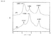
高磁場シフトNMRピークは、通常の水素化物イオンと比較して減少した半径を有し、またプロトンの反磁性遮蔽が増加した、より低いエネルギー状態の水素の存在の直接的な証拠である。
外部テトラメチルシラン(TMS)と比較した新規な化合物
元素分析により、これらの化合物はアルカリ金属、ハロゲン、および水素を含有するのみであると確認され[14、16]、この組成物の高磁場シフト水素化物NMRピークを有する既知の水素化物化合物は、文献中に見つけることができなかった。通常のアルカリ水素化物単体またはアルカリハロゲン化物との混合は、低磁場シフトピークを示す[3、14〜16]。文献から、高磁場NMRピークの可能な源としての
さらなる特性決定として、ハイドリノ水素化物
[好ましい実施例の詳細な説明]
(水素触媒反応器)
本発明による、エネルギーおよびより低エネルギーの水素種を生成する水素触媒反応器50が図1Aに示されるが、エネルギー反応混合物54を含有する槽52、熱交換器60、ならびに蒸気発生器62およびタービン70等の電力変換器を備える。一実施形態において、触媒作用は、源56からの原子水素を触媒58に反応させてより低エネルギーの水素「ハイドリノ」を形成し電力を発生するステップを含む。水素および触媒を含む反応混合物が反応してより低エネルギーの水素を形成する際に、熱交換器60は触媒反応により放出された熱を吸収する。熱交換器は、蒸気発生器62と熱交換し、該発生器は交換器60からの熱を吸収して蒸気を生成する。エネルギー反応器50は、蒸気発生器62からの蒸気を受けて電力発生器80に機械力を供給するタービン70をさらに備え、電力発生器は蒸気エネルギーを電気エネルギーに変換し、これは負荷90が受けて仕事を生成または散逸する。
Detailed Description of the Preferred Embodiment
(Hydrogen catalytic reactor)
A hydrogen catalyzed
一実施形態において、エネルギー反応混合物54は、供給通路42から供給される固体燃料等のエネルギー放出材料56を含む。反応混合物は、水素同位体原子源または分子水素同位体源、および共鳴的に
水素源は、水素ガス、熱解離を含む水の解離、水の電気分解、水素化物からの水素、または金属−水素溶液からの水素であってもよい。別の実施形態において、エネルギー放出材料56の分子水素が、混合物54の分子水素解離触媒により原子水素に解離する。そのような解離触媒はまた、水素、ジューテリウム、またはトリチウム原子および/もしくは分子を吸収することができ、また、例えば、パラジウムおよび白金等の貴金属の元素、化合物、合金、または混合物、モリブデンおよびタングステン等の耐熱金属、ニッケルおよびチタン等の遷移金属、ニオブおよびジルコニウム等の内部遷移金属、ならびに、Mills先行出版物にリストされているような他の材料を含む。好ましくは、解離剤は、Pt、Pd、Ru、Ir、Re、またはRh等の貴金属、またはAl2O3、SiO2、またはこれらの組み合わせの上のNi等、大表面積を有する。
The hydrogen source may be hydrogen gas, water dissociation including thermal dissociation, water electrolysis, hydrogen from a hydride, or hydrogen from a metal-hydrogen solution. In another embodiment, the molecular hydrogen of the
一実施形態において、触媒は、
好ましい実施形態において、触媒源は、触媒供給通路41から供給される触媒材料58を含み、これは典型的には、近似的に
(水素触媒反応器および電力システム)
電力システムの一実施形態において、熱は熱交換媒体を有する熱交換器により取り除かれる。熱交換器は水冷壁であってもよく、媒体は水であってもよい。熱は、暖房およびプロセス加熱のために直接移動され得る。代替として、水等の熱交換媒体は、蒸気への変換等、相変化する。変換は蒸気発生器内で生じ得る。蒸気タービンおよび発生器等の熱機関において蒸気を使用して発電することができる。
(Hydrogen catalytic reactor and power system)
In one embodiment of the power system, heat is removed by a heat exchanger having a heat exchange medium. The heat exchanger may be a water-cooled wall and the medium may be water. Heat can be transferred directly for heating and process heating. Alternatively, a heat exchange medium such as water undergoes a phase change, such as conversion to steam. Conversion can occur in the steam generator. Electricity can be generated using steam in heat engines such as steam turbines and generators.
本発明による、燃料のリサイクルまたは再生のための水素触媒エネルギーおよびより低エネルギーの水素種を生成する反応器5の実施形態が図2Aに示されているが、固体燃料反応混合物11を含むボイラー10、水素源12、蒸気管および蒸気発生器13、タービン14等の電力変換器、水凝縮器16、給水源17、固体燃料リサイクラ18、ならびに水素二ハイドリノガスセパレータ19を備える。ステップ1において、触媒源および水素源を含む固体燃料が反応してハイドリノおよびより低エネルギーの水素生成物を形成する。ステップ2において、火力生成を維持するために消費された燃料が再処理されてボイラー10に再供給される。ボイラー10で生成された熱は管および蒸気発生器13内で蒸気を形成し、これがタービン14に送達され、次いで発生器を駆動することにより発電される。ステップ3において、水凝縮器16により水が凝縮される。水源17によりいかなる水の損失も補給され、熱から電力への変換を維持するためのサイクルが完結する。ステップ4において、ハイドリノ水素化物化合物および二ハイドリノガス等のより低エネルギーの水素生成物を除去することができ、未反応水素を燃料リサイクラ18に戻すことができるか、または水素源12が消費された燃料に再び添加されてリサイクル燃料を補完することができる。ガス生成物および未反応水素は、水素−二ハイドリノガスセパレータ19により分離され得る。いかなる生成物ハイドリノ水素化物化合物も、固体燃料リサイクラ18を使用して分離および除去され得る。処理は、固体燃料が返却されながら、ボイラ内で、またはボイラの外部で行うことができる。したがって、システムは、反応物質および生成物を移動させて消費燃料の除去、再生、および再供給を達成するために、ガスおよび塊輸送器の少なくとも1つをさらに備えることができる。ハイドリノ形成中に消費された水素のための補給水素は、燃料再処理中に源12から添加され、リサイクルされた未消費の水素を含み得る。リサイクルされた燃料は、電力プラントが発電するのを駆動するように火力の生成を維持する。
An embodiment of a
好ましい実施形態において、反応混合物は、さらに反応してハイドリノを形成する原子もしくは分子触媒および原子水素の反応物質を生成し得る種を含み、触媒および原子水素の生成により形成される生成物種は、少なくとも生成物を水素と反応させるステップにより再生され得る。一実施形態において、反応器は、流動床反応器をさらに含み得る移動床反応器を含み、反応物質は連続的に供給され、副生成物が除去および再生されて反応器に戻される。一実施形態において、反応物質が再生される際、ハイドリノ水素化物化合物または二ハイドリノ分子等のより低エネルギーの水素生成物が回収される。さらに、反応物質の再生中、ハイドリノ水素化物イオンは、他の化合物に形成され得るか、または二ハイドリノ分子に変換され得る。 In a preferred embodiment, the reaction mixture further comprises an atomic or molecular catalyst that reacts to form a hydrino and a species capable of producing a reactant of atomic hydrogen, and the product species formed by the production of the catalyst and atomic hydrogen is at least It can be regenerated by reacting the product with hydrogen. In one embodiment, the reactor includes a moving bed reactor that may further include a fluidized bed reactor, where the reactants are continuously fed and by-products are removed and regenerated and returned to the reactor. In one embodiment, when the reactants are regenerated, lower energy hydrogen products such as hydrino hydride compounds or dihydrino molecules are recovered. Furthermore, during regeneration of the reactants, hydrino hydride ions can be formed into other compounds or converted into dihydrino molecules.
電力システムは、表面温度を反応セルの温度よりも低い値に制御する温度制御手段により触媒蒸気圧を維持するための触媒凝縮手段をさらに備えることができる。表面温度は、触媒の所望の蒸気圧を提供する所望の値に維持される。一実施形態において、触媒凝縮手段は、セル内のチューブグリッドである。熱交換器を備える一実施形態において、伝熱媒体の流速は、凝縮器を主熱交換器よりも低い所望の温度に維持する速度に制御され得る。一実施形態において、作動媒体は水であり、凝縮器がより低い所望の温度となるように、流速は水冷壁よりも凝縮器でより高い。作動媒体の別個のストリームが再結合されて、暖房およびプロセス加熱のため、または蒸気への変換のために移動され得る。 The electric power system may further include a catalyst condensing means for maintaining the catalyst vapor pressure by a temperature control means for controlling the surface temperature to a value lower than the temperature of the reaction cell. The surface temperature is maintained at a desired value that provides the desired vapor pressure of the catalyst. In one embodiment, the catalyst condensation means is a tube grid in the cell. In one embodiment with a heat exchanger, the flow rate of the heat transfer medium can be controlled to a rate that maintains the condenser at a desired temperature lower than the main heat exchanger. In one embodiment, the working medium is water and the flow rate is higher at the condenser than at the water cooling wall so that the condenser is at a lower desired temperature. Separate streams of working medium can be recombined and moved for heating and process heating or for conversion to steam.
本エネルギーの発明は、参照により本明細書に組み入れられるMills先行出版物にさらに記載されている。本発明のセルは、以前に説明されたものを含み、また本明細書に開示される触媒、反応混合物、方法、およびシステムをさらに含む。本発明の電界セルエネルギー反応器、プラズマ電界反応器、バリア電極反応器、RFプラズマ反応器、圧縮ガスエネルギー反応器、ガス放出エネルギー反応器、マイクロ波セルエネルギー反応器、ならびにグロー放電セルとマイクロ波およびRFプラズマ反応器の組み合わせは、水素源と、触媒の固体、溶融物、液体、およびガスの触媒源のうちの1つと、水素および触媒を含有する槽であって、より低エネルギーの水素を形成する反応は、水素と触媒の接触により、または
(水素ガスセルおよび固体燃料反応器)
本発明の実施形態によれば、ハイドリノおよび電力を生成するための反応器は、水素ガスセルの形態をとり得る。本発明のガスセル水素反応器を、図3Aに示す。反応物質ハイドリノは、触媒との触媒反応により提供される。触媒作用は、気体状態または固体状態または液体状態において生じ得る。
(Hydrogen gas cell and solid fuel reactor)
According to embodiments of the present invention, the hydrino and reactor for generating electrical power may take the form of a hydrogen gas cell. A gas cell hydrogen reactor of the present invention is shown in FIG. 3A. The reactant hydrino is provided by catalytic reaction with a catalyst. Catalysis can occur in the gaseous state or in the solid or liquid state.
図3Aの反応器は、真空または大気圧を越える圧力を含有し得るチャンバ200を有する反応槽207を備える。チャンバ200と連通する水素源221は、水素供給通路242を通して水素をチャンバに送給する。コントローラ222は、水素供給通路242を通した層への水素の圧力および流れを制御するように位置している。圧力センサ223は、層内の圧力を監視する。真空ポンプ256は、真空ライン257を通してチャンバから排気する。
The reactor of FIG. 3A comprises a
一実施形態において、触媒作用は気相で生じる。触媒は、セル温度を高温に維持することによりガス状とすることができ、これは一方で触媒の蒸気圧を決定する。原子および/または分子水素反応物質はまた、任意の圧力範囲内であってよい所望の圧力に維持される一実施形態において、圧力は大気圧未満、好ましくは約10ミリトルから約100トルの範囲内である。別の実施形態において、圧力は、金属源および対応する水素化物、例えば金属水素化物等の触媒源の混合物を、セル内で所望の運転温度に維持することにより決定される。 In one embodiment, the catalysis occurs in the gas phase. The catalyst can be made gaseous by maintaining the cell temperature at a high temperature, which in turn determines the vapor pressure of the catalyst. In one embodiment, the atomic and / or molecular hydrogen reactant is also maintained at a desired pressure, which may be in any pressure range, and the pressure is less than atmospheric pressure, preferably in the range of about 10 millitorr to about 100 torr. It is. In another embodiment, the pressure is determined by maintaining a mixture of a metal source and a corresponding hydride, for example a catalyst source such as a metal hydride, at a desired operating temperature in the cell.
ハイドリノ原子を生成するための触媒源250は、触媒貯蔵部295内に配置することができ、加熱によりガス状触媒を形成することができる。反応槽207は、触媒貯蔵部295から反応チャンバ200へのガス状触媒の通過のための触媒供給通路241を有する。代替として、触媒は、反応層内の耐薬品性の開いた容器、例えばボート内に配置されてもよい。
The
水素源は、水素ガスおよび分子水素であってよい。水素は、分子水素解離触媒により原子水素に解離され得る。そのような解離触媒または解離剤は、例えば、ラネーニッケル(R−Ni)、貴重金属または貴金属、および担体上の貴重金属または貴金属を含む。貴重金属または貴金属は、Pt、Pd、Ru、Ir、およびRhであってよく、担体は、Ti、Nb、Al2O3、SiO2およびこれらの組み合わせのうちの少なくとも1つであってよい。さらなる解離剤は、水素スピルオーバー触媒を含み得る炭素上PtまたはPd、ニッケル繊維マット、Pdシート、Tiスポンジ、TiまたはNiスポンジまたはマット上に電気メッキされたPtまたはPd、TiH、PtブラックおよびPdブラック、耐熱金属、例えばモリブデンおよびタングステン等、遷移金属、例えばニッケルおよびチタン等、内部遷移金属、例えばニオブおよびジルコニウム等、ならびに、Mills先行出版物に列記されているような他の材料である。好ましい実施形態において、水素は、PtまたはPd上で解離する。PtまたはPdは、チタンまたはAl2O3等の担体材料上に被覆され得る。別の実施形態において、解離剤は、タングステンまたはモリブデン等の耐熱金属であり、解離材料は、図3Aの断面図で示されるような加熱コイルの形態をとり得る温度制御手段230により高温に維持され得る。加熱コイルは、電源225により電力供給される。好ましくは、解離材料は、セルの運転温度に維持される。また、解離剤は、さらに、より効果的に解離するようにセル温度を超える温度で使用されてもよく、また高温は触媒が解離剤上に凝縮されるのを防ぐことができる。水素解離剤は、電源285により電力供給される280等の熱フィラメントによっても提供され得る。
The hydrogen source may be hydrogen gas and molecular hydrogen. Hydrogen can be dissociated into atomic hydrogen by a molecular hydrogen dissociation catalyst. Such dissociation catalysts or dissociators include, for example, Raney nickel (R-Ni), a valuable or noble metal, and a valuable or noble metal on the support. The precious metal or noble metal may be Pt, Pd, Ru, Ir, and Rh, and the support may be at least one of Ti, Nb, Al 2 O 3 , SiO 2 and combinations thereof. Further dissociators are Pt or Pd on carbon, which can contain a hydrogen spillover catalyst, nickel fiber mat, Pd sheet, Ti sponge, Ti or Ni sponge or Pt or Pd, TiH, Pt black and Pd black electroplated on the mat. Refractory metals such as molybdenum and tungsten, transition metals such as nickel and titanium, internal transition metals such as niobium and zirconium, and other materials as listed in Mills prior publications. In preferred embodiments, the hydrogen dissociates on Pt or Pd. Pt or Pd can be coated on a support material such as titanium or Al 2 O 3 . In another embodiment, the dissociator is a refractory metal such as tungsten or molybdenum, and the dissociation material is maintained at an elevated temperature by temperature control means 230 that may take the form of a heating coil as shown in the cross-sectional view of FIG. 3A. obtain. The heating coil is powered by a
一実施形態において、水素解離は、解離した水素原子がガス状触媒と接触してハイドリノ原子を生成するように生じる。触媒蒸気圧は、電源272により電力供給される触媒貯蔵部ヒータ298により触媒貯蔵部295の温度を制御することにより所望の圧力に維持される。触媒が反応器内のボートに含有される場合、触媒蒸気圧は、触媒ボートの電源を調節してボートの温度を制御することにより、所望の値に維持される。セル温度は、電源225により電力供給される加熱コイル230により所望の運転温度に制御することができる。セル(浸透セルと呼ばれる)は、内部反応チャンバ200および外部水素貯蔵部290をさらに備え、2つのチャンバを隔てる壁291を通した水素の拡散により水素がセルに供給され得るようにすることができる。拡散速度を制御するために、壁の温度をヒータにより制御することができる。拡散速度は、水素貯蔵部内の水素圧力を制御することによりさらに制御することができる。
In one embodiment, hydrogen dissociation occurs such that the dissociated hydrogen atoms come into contact with the gaseous catalyst to produce hydrino atoms. The catalyst vapor pressure is maintained at a desired pressure by controlling the temperature of the
触媒圧力を所望のレベルに維持するために、水素源としての浸透性を有するセルを封止することができる。代替として、セルは、さらに高温弁を各入口または出口に備え、反応ガス混合物に接触する弁が所望の温度に維持されるようにすることができる。セルは、より低エネルギーの水素種および/または増加結合エネルギー水素化合物を選択的に収集するためにゲッターまたはトラップ255をさらに備えることができ、また、二ハイドリノガス生成物を放出するための選択弁206をさらに備えることができる。
In order to maintain the catalyst pressure at a desired level, a permeable cell as a hydrogen source can be sealed. Alternatively, the cell may further include a hot valve at each inlet or outlet so that the valve in contact with the reaction gas mixture is maintained at the desired temperature. The cell can further comprise a getter or
触媒は、原子リチウム、カリウム、またはセシウム、NaH分子およびハイドリノ原子の群のうちの少なくとも1つであってよく、触媒作用は、不均化反応を含む。リチウム触媒は、セル温度を500〜1000℃の範囲に維持することによりガス状とすることができる。好ましくは、セルは、500〜750℃の範囲内に維持される。セル圧力は大気圧未満、好ましくは約10ミリトルから約100トルの範囲内に維持され得る。最も好ましくは、触媒金属および対応する水素化物、例えばリチウムおよび水素化リチウム、カリウムおよび水素化カリウム、ナトリウムおよび水素化ナトリウム、ならびにセシウムおよび水素化セシウムの混合物を、所望の運転温度に維持されるセル内に維持することにより、触媒および水素圧力のうちの少なくとも1つが決定される。気相の触媒は、金属またはリチウム金属源からのリチウム原子を含むことができる。好ましくは、リチウム触媒は、500〜1000℃の運転温度範囲のリチウム金属および水素化リチウムの混合物により決定される圧力に維持され、最も好ましくは、500〜750℃の運転温度範囲のセルによる圧力に維持される。他の実施形態において、K、Cs、およびNaがLiに置き換わり、触媒は原子K、原子Cs、および分子NaHである。 The catalyst may be at least one of the group of atomic lithium, potassium, or cesium, NaH molecules and hydrino atoms, and the catalysis includes a disproportionation reaction. The lithium catalyst can be made gaseous by maintaining the cell temperature in the range of 500-1000 ° C. Preferably, the cell is maintained in the range of 500-750 ° C. The cell pressure may be maintained below atmospheric pressure, preferably in the range of about 10 millitorr to about 100 torr. Most preferably, the catalyst metal and the corresponding hydride, such as lithium and lithium hydride, potassium and potassium hydride, sodium and sodium hydride, and a mixture of cesium and cesium hydride are maintained at the desired operating temperature. By maintaining within, at least one of the catalyst and the hydrogen pressure is determined. The gas phase catalyst can include lithium atoms from a metal or lithium metal source. Preferably, the lithium catalyst is maintained at a pressure determined by a mixture of lithium metal and lithium hydride in the operating temperature range of 500-1000 ° C, most preferably at a pressure by the cell in the operating temperature range of 500-750 ° C. Maintained. In other embodiments, K, Cs, and Na replace Li, and the catalyst is atomic K, atomic Cs, and molecular NaH.
触媒貯蔵部またはボートを備えるガスセル反応器の一実施形態において、ガス状Na、NaH触媒、またはLi、K、およびCs蒸気等のガス状触媒は、セル蒸気の源である貯蔵部またはボート内の蒸気と比較して、セル内で過熱状態に維持される。一実施形態において、過熱蒸気は、水素解離剤上、または、以下に開示されるような金属および金属水素化物分子のうちの少なくとも1つの解離剤上の触媒の凝縮を低減する。貯蔵部またはボートからの触媒としてLiを含む一実施形態において、貯蔵部またはボートは、Liが蒸発する温度に維持される。H2は、貯蔵部温度においてLiHの著しいモル分率を形成する圧力より低い圧力に維持することができる。この条件を達成する圧力および温度は、所与の等温線におけるH2圧力対LiHモル分率の図6.1[40]等、Muellerらのデータプロットから決定することができる。一実施形態において、解離剤を含有するセル反応チャンバは、Liが壁または解離剤上で凝縮しないように、より高い温度で運転される。H2は、貯蔵部からセルに流入して触媒移動率を増加させ得る。触媒貯蔵部からセルへ、次いでセル外へといった流れは、反応のハイドリノ生成物阻害を防ぐためにハイドリノ生成物を除去する手段である。他の実施形態において、K、Cs、およびNaがLiに置き換わり、触媒は原子K、原子Cs、および分子NaHである。 In one embodiment of a gas cell reactor comprising a catalyst reservoir or boat, gaseous catalysts such as gaseous Na, NaH catalyst, or Li, K, and Cs vapor are contained in the reservoir or boat that is the source of cell vapor. Compared to steam, it is kept superheated in the cell. In one embodiment, the superheated steam reduces the condensation of the catalyst on the hydrogen dissociator or on at least one of the metal and metal hydride molecules as disclosed below. In one embodiment that includes Li as a catalyst from the reservoir or boat, the reservoir or boat is maintained at a temperature at which Li evaporates. H 2 can be maintained at a pressure lower than the pressure that forms a significant mole fraction of LiH at the reservoir temperature. Pressure and temperature to achieve this condition can be determined from the H 2 pressure versus LiH mole fraction Figure 6.1 [40], etc., data plots of Mueller et al in a given isotherm. In one embodiment, the cell reaction chamber containing the dissociator is operated at a higher temperature so that Li does not condense on the walls or dissociator. H 2 may flow into the cell to increase the catalyst transfer rate from the reservoir. The flow from the catalyst reservoir to the cell and then out of the cell is a means of removing the hydrino product to prevent hydrino product inhibition of the reaction. In other embodiments, K, Cs, and Na replace Li, and the catalyst is atomic K, atomic Cs, and molecular NaH.
水素は、水素源から反応に供給される。好ましくは、水素は、水素貯蔵部からの浸透により供給される。水素貯蔵部の圧力は、10トルから10,000トル、好ましくは100トルから1000トル、最も好ましくは約大気圧である。セルは、約100℃から3000℃の温度、好ましくは約100℃から1500℃の温度、最も好ましくは約500℃から800℃の温度で運転することができる。 Hydrogen is supplied to the reaction from a hydrogen source. Preferably, the hydrogen is supplied by infiltration from a hydrogen reservoir. The pressure in the hydrogen reservoir is from 10 Torr to 10,000 Torr, preferably from 100 Torr to 1000 Torr, and most preferably about atmospheric pressure. The cell can be operated at a temperature of about 100 ° C. to 3000 ° C., preferably about 100 ° C. to 1500 ° C., most preferably about 500 ° C. to 800 ° C.
水素源は、添加された水素化物の分解からであってもよい。浸透によりH2を供給するセル設計は、封止された槽内に配置された内部金属水素化物を備えるものであり、高温で原子Hが浸透により送出される。槽は、Pd、Ni、Ti、またはNbであってよい。一実施形態において、水素化物は、水素化物を含有するNb管等の封止チューブ内に配置され、スウェージロック等の封止器具により両端を封止される。封止される場合、水素化物は、アルカリまたはアルカリ土類水素化物であり得る。または、この場合、および内部水素化物試薬の場合、水素化物は、塩類似水素化物、水素化チタン、バナジウム、ニオブ、および水素化タンタル、水素化ジルコニウムおよびハフニウム、希土類水素化物、水素化イットリウムおよびスカンジウム、遷移元素水素化物、内部金属水素化物、ならびに、W.M.Muellerら[40]により示されるこれらの合金の群のうちの少なくとも1種であり得る。 The hydrogen source may be from decomposition of added hydride. The cell design that supplies H 2 by infiltration comprises an internal metal hydride placed in a sealed vessel, and atoms H are delivered by infiltration at high temperatures. The tank may be Pd, Ni, Ti, or Nb. In one embodiment, the hydride is placed in a sealing tube, such as an Nb tube containing hydride, and sealed at both ends with a sealing instrument, such as a Swagelok. When sealed, the hydride can be an alkali or alkaline earth hydride. Or in this case, and in the case of internal hydride reagents, the hydrides are salt-like hydrides, titanium hydrides, vanadium, niobium, and tantalum hydrides, zirconium hydrides and hafnium, rare earth hydrides, yttrium hydrides, and scandiums. , Transition element hydrides, internal metal hydrides, and W.W. M.M. It may be at least one of the group of these alloys shown by Mueller et al. [40].
一実施形態において、水素化物および運転温度±200℃は、各水素化物分解温度に基づき、以下のリストのうちの少なくとも1つである。 In one embodiment, the hydride and operating temperature ± 200 ° C. is at least one of the following lists based on each hydride decomposition temperature.
約800℃の運転温度での希土類水素化物、約700℃の運転温度での水素化ランタン、約750℃の運転温度での水素化ガドリニウム、約750℃の運転温度での水素化ネオジム、約800℃の運転温度での水素化イットリウム、約800℃の運転温度での水素化スカンジウム、約850〜900℃の運転温度での水素化イッテルビウム、約450℃の運転温度での水素化チタン、約950℃の運転温度での水素化セリウム、約700℃の運転温度での水素化プラセオジム、約600℃の運転温度での水素化ジルコニウム−チタン(50%/50%)、約450℃の運転温度でのRb/RbHまたはK/KH等のアルカリ金属/アルカリ金属水素化物混合物、および約900〜1000℃の運転温度でのBa/BaH2等のアルカリ土類金属/アルカリ土類水素化物混合物。 Rare earth hydrides at an operating temperature of about 800 ° C., lanthanum hydride at an operating temperature of about 700 ° C., gadolinium hydride at an operating temperature of about 750 ° C., neodymium hydride at an operating temperature of about 750 ° C., about 800 Yttrium hydride at an operating temperature of about 800 ° C, scandium hydride at an operating temperature of about 800 ° C, ytterbium hydride at an operating temperature of about 850-900 ° C, titanium hydride at an operating temperature of about 450 ° C, about 950 Cerium hydride at an operating temperature of ℃, praseodymium hydride at an operating temperature of about 700 ℃, zirconium hydride-titanium (50% / 50%) at an operating temperature of about 600 ℃, at an operating temperature of about 450 ℃ Alkali metal / alkali metal hydride mixtures such as Rb / RbH or K / KH and alkaline earth gold such as Ba / BaH2 at an operating temperature of about 900-1000 ° C / Alkaline earth hydride mixture.
気体状態の金属は、二原子共有結合分子を含む。本発明の目的は、Li、さらにKおよびCs等の原子触媒を提供することである。したがって、反応器は、金属分子(「MM」)および金属水素化物分子(「MH」)のうちの少なくとも1つの解離剤をさらに含むことができる。好ましくは、触媒源、H2源、ならびにMM、MH、およびHHの解離剤(式中Mは原子触媒である)は、例えば温度および反応物質濃度等の所望のセル条件で運転するように適合する。H2の水素化物源が使用される場合、一実施形態において、その分解温度は、触媒の所望の蒸気圧を生成する温度の範囲内にある。水素源が水素貯蔵部から反応チャンバへの浸透である場合、連続運転のための好ましい触媒源は、SrおよびLi金属であるが、これは、浸透が生じる温度におけるその蒸気圧のそれぞれが0.01トルから100トルの所望の範囲内となり得るためである。浸透セルの別の実施形態において、セルは、浸透を可能とする高温で運転され、次いでセル温度は、所望の圧力で揮発性触媒の蒸気圧を維持する温度まで低下される。 Gas state metals include diatomic covalently bonded molecules. The object of the present invention is to provide atomic catalysts such as Li, and also K and Cs. Thus, the reactor can further comprise at least one dissociator of a metal molecule (“MM”) and a metal hydride molecule (“MH”). Preferably, the catalyst source, H 2 source, and dissociator of MM, MH, and HH (where M is an atomic catalyst) are adapted to operate at the desired cell conditions such as temperature and reactant concentration. To do. When a hydride source of H 2 is used, in one embodiment, the decomposition temperature is in the range of temperatures that produce the desired vapor pressure of the catalyst. When the hydrogen source is permeation from the hydrogen reservoir to the reaction chamber, the preferred catalyst sources for continuous operation are Sr and Li metals, each of which has a vapor pressure of 0. 0 at the temperature at which permeation occurs. This is because it can be within a desired range from 01 torr to 100 torr. In another embodiment of the osmosis cell, the cell is operated at an elevated temperature that allows for osmosis, and then the cell temperature is lowered to a temperature that maintains the vapor pressure of the volatile catalyst at the desired pressure.
ガスセルの一実施形態において、解離剤は、源から触媒およびHを生成するための手段を備える。Ti上Pt、またはPd、イリジウムもしくはロジウム単体、またはTi等の基材上のもの等の表面触媒はまた、触媒および水素原子の組み合わせの分子の解離剤としての役割を果たすことができる。好ましくは、解離剤は、Pt/Al2O3またはPd/Al2O3等、大表面積を有する。 In one embodiment of the gas cell, the dissociator comprises a means for producing catalyst and H from a source. Surface catalysts such as Pt on Ti, or Pd, iridium or rhodium alone, or on a substrate such as Ti can also serve as a molecular dissociator for the combination of catalyst and hydrogen atoms. Preferably, the dissociator has a large surface area, such as Pt / Al 2 O 3 or Pd / Al 2 O 3 .
H2源はまた、H2ガスであってもよい。この場合、圧力を監視および制御することができる。これは、それぞれKまたはCs金属およびLiNH2等の触媒および触媒源を用いて可能であるが、これは、これらが低温で揮発性であるためであり、高温弁の使用を可能とするからである。LiNH2はまた、Liセルの必要な運転温度を低下させ、腐食性がより低く、フィラメントが水素解離剤として機能するプラズマおよびフィラメントセルの場合、フィードスルーを使用した長期間運転を可能とする。 The H 2 source may also be H 2 gas. In this case, the pressure can be monitored and controlled. This is because it is possible with K or Cs metal and LiNH 2 such catalysts and a source of catalyst, respectively, this is because they are volatile at low temperatures allows the use of high temperature valves is there. LiNH 2 also lowers the required operating temperature of the Li cell and allows long-term operation using feedthrough in the case of plasma and filament cells where the corrosivity is lower and the filament functions as a hydrogen dissociator.
触媒としてNaHを有するガスセル水素反応器のさらなる実施形態は、反応器セル内に解離剤および貯蔵部内にNaを有するフィラメントを備える。H2は、貯蔵部を通って主チャンバに流入することができる。電力は、ガス流速、H2圧力、およびNa蒸気圧を制御することにより制御され得る。後者は、貯蔵部温度を制御することにより制御され得る。別の実施形態において、ハイドリノ反応は、外部ヒータでの加熱により開始され、原子Hは解離剤により提供される。 A further embodiment of a gas cell hydrogen reactor having NaH as a catalyst comprises a filament having a dissociator in the reactor cell and Na in the reservoir. H 2 can flow into the main chamber through the reservoir. The power can be controlled by controlling the gas flow rate, H 2 pressure, and Na vapor pressure. The latter can be controlled by controlling the reservoir temperature. In another embodiment, the hydrino reaction is initiated by heating with an external heater and atomic H is provided by a dissociator.
本発明はまた、二ハイドリノ分子およびハイドリノ水素化物化合物等の本発明の増加結合エネルギー水素化合物を生成するための他の反応器に関する。触媒作用のさらなる生成物は、プラズマ、光、および電力である。そのような反応器は、以降、「水素反応器」または「水素セル」と呼ばれる。水素反応器は、ハイドリノを生成するためのセルを備える。ハイドリノを生成するためのセルは、例えば、ガスセル、ガス放出セル、プラズマトーチセル、またはマイクロ波電力セル等の形態をとり得る。これらの例示的セルは、網羅的であることを意図しないが、Mills先行出版物に開示されており、参照により組み入れられる。これらのセルはそれぞれ、原子水素源、ハイドリノ形成のための固体、溶融物、液体、またはガス状触媒のうちの少なくとも1つ、および水素とハイドリノ形成のための触媒とを反応させるための槽とを備える。本明細書で使用される場合、および本発明により企図されるように、「水素」という用語は、別段の指定がない限り、
(水素ガス放電電力およびプラズマセルならびに反応器)
本発明の水素ガス放電電力およびプラズマセルならびに反応器を、図4Aに示す。図4Aの水素ガス放電電力およびプラズマセルならびに反応器は、チャンバ300を有する水素ガス入りグロー放電真空槽315を備える、ガス放電セル307を含む。水素源322は、水素供給路342を介して、制御弁325を通して、チャンバ300に水素を供給する。触媒は、セルチャンバ300に含有される。電圧および電流源330は、電流にカソード305とアノード320との間を通過させる。電流は逆にすることが可能であり得る。
(Hydrogen gas discharge power and plasma cell and reactor)
The hydrogen gas discharge power and plasma cell and reactor of the present invention are shown in FIG. 4A. The hydrogen gas discharge power and plasma cell and reactor of FIG. 4A include a
一実施形態では、カソード305の材料は、Fe、Dy、Be、またはPd等の触媒源であり得る。水素ガス放電電力およびプラズマセルならびに反応器の別の実施形態では、槽の壁313は、導電性であり、電極305と置き換わるカソードとして機能し、アノード320は、ステンレススチール製中空アノード等の中空であり得る。放電は、触媒源を触媒に気化することができる。分子水素は、ハイドリノおよびエネルギーの生成のための水素原子を形成するために、放電によって解離することができる。チャンバ内の水素解離剤によって、さらなる解離がもたらされ得る。
In one embodiment, the material of the
気相において触媒作用が生じる、水素ガス放電電力およびプラズマセルならびに反応器の別の実施形態は、制御可能なガス状触媒を利用する。ハイドリノへの変換のためのガス状水素原子は、分子水素ガスの放電によって提供される。ガス放電セル307は、触媒容器395から反応チャンバ300へのガス状触媒350の通過のための触媒供給路341を有する。触媒容器395は、反応チャンバ300にガス状触媒を提供するために、電力供給372を有する触媒容器加熱器392によって加熱される。触媒の蒸気圧は、加熱器392をその電力供給372を用いて調節することによって、触媒容器395の温度を制御することによって制御される。反応器は、選択的排出弁301をさらに備える。ガス放電セル内に位置付けられる、ステンレススチール、タングステン、またはセラミックボート等の化学的耐性を有する開放容器は、触媒を含有することができる。触媒ボート内の触媒は、反応チャンバにガス状触媒を提供するために、関連した電力供給を使用したボート加熱器で加熱されてもよい。代替として、グローガス放電セルは、ボート内の触媒が気相へと昇華、沸騰、または揮発させられるように、高温で作動される。触媒の蒸気圧は、加熱器をその電力供給で調節することによって、ボートまたは放電セルの温度を制御することによって制御される。触媒がセル内で液化することを防止するために、温度は、触媒源、触媒容器395、または触媒ボートの温度よりも高く維持される。
Another embodiment of the hydrogen gas discharge power and plasma cell and reactor that catalyses in the gas phase utilizes a controllable gaseous catalyst. Gaseous hydrogen atoms for conversion to hydrino are provided by the discharge of molecular hydrogen gas. The
好ましい実施形態では、触媒作用は気相において生じ、リチウムが触媒であり、リチウム金属またはLiNH2等のリチウム化合物等の原子リチウム源は、セル温度を約300〜1000℃の範囲内に維持することによって、気体の状態にされる。最も好ましくは、セルは、約500〜750℃の範囲内に維持される。原子および/または分子水素反応物質質は、大気圧未満、好ましくは、約10ミリトール〜約100Torrの範囲内の圧力で維持され得る。最も好ましくは、圧力は、所望の作動温度で維持されるセル内に、リチウム金属および水素化リチウムの混合物を維持することによって決定される。作動温度範囲は、好ましくは、約300〜1000℃の範囲内であり、最も好ましくは、圧力は、約300〜750℃の作動温度範囲でのセルで達成される圧力である。セルは、電力供給385によって電力供給される図4Aの380等の加熱コイルによって、所望の作動温度で制御することができる。セルは、内部反応チャンバ300および外部水素容器390をさらに備えることができ、水素を、2つのチャンバを分離する壁313を通した水素の拡散によって、セルに供給することができる。壁の温度は、拡散率を制御するために加熱器で制御することができる。拡散率は、水素容器内の水素圧を制御することによってさらに制御され得る。
In a preferred embodiment, the catalysis occurs in the gas phase, lithium is the catalyst, and an atomic lithium source such as lithium metal or a lithium compound such as LiNH 2 maintains the cell temperature within the range of about 300-1000 ° C. By making it into a gas state. Most preferably, the cell is maintained in the range of about 500-750 ° C. The atomic and / or molecular hydrogen reactant may be maintained at a pressure below atmospheric pressure, preferably in the range of about 10 mTorr to about 100 Torr. Most preferably, the pressure is determined by maintaining a mixture of lithium metal and lithium hydride in a cell maintained at the desired operating temperature. The operating temperature range is preferably within the range of about 300-1000 ° C, and most preferably the pressure is the pressure achieved in the cell at an operating temperature range of about 300-750 ° C. The cell can be controlled at the desired operating temperature by a heating coil such as 380 in FIG. 4A powered by
本発明のプラズマセルの一実施形態は、LiおよびLiNH2等の反応物質質を再生する。一実施形態では、方程式(32)および(37)によって得られる反応が起こり、ハイドリノ生成によって放出される非常に過剰なエネルギーで、ハイドリノ反応物質質LiおよびHを生成する。次いで、生成物は水素源によって水素化される。LiHが形成される場合、より低エネルギーの水素触媒反応物質を再生するための一反応は、方程式(66)によって与えられる。これは、水素プラズマセル内のカソード領域等の、プラズマセル内の反応領域に配置される反応物質で達成され得る。反応は、
LiH+e−→LiおよびH− (30)
であり得、次いで、反応
Li2NH+H−→Li+LiNH2 (31)
は、Li+LiNH2の定常状態レベルを維持するために、ある程度起こり得る。H2圧力、電子密度、およびエネルギーを、ハイドリノ反応物質Li+LiNH2を再生する最大限または所望の程度の反応を達成するために制御することができる。
One embodiment of a plasma cell of the present invention reproduces the reactants quality such as Li and LiNH 2. In one embodiment, the reaction obtained by equations (32) and (37) occurs, producing hydrino reactants Li and H with very excess energy released by hydrino production. The product is then hydrogenated with a hydrogen source. When LiH is formed, one reaction to regenerate lower energy hydrogen catalyzed reactant is given by equation (66). This can be achieved with a reactant that is placed in a reaction region within the plasma cell, such as a cathode region within the hydrogen plasma cell. The reaction is
LiH + e− → Li and H− (30)
And then the reaction
Li 2 NH + H− → Li + LiNH 2 (31)
Can occur to some extent to maintain a steady state level of Li + LiNH 2 . H 2 pressure, electron density, and the energy can be controlled in order to achieve maximum or desired degree of reaction to play hydrino reactants Li + LiNH 2.
一実施形態では、混合物は、プラズマ反応中に撹拌または混合される。本発明のプラズマ再生システムおよび方法のさらなる実施形態では、セルは、加熱された平底ステンレススチール製プラズマチャンバを備える。LiHおよびLi2NHは、溶融Li中の混合物を成す。ステンレススチールは磁性を有しないため、液体混合物は、平底プラズマ反応器が置かれる撹拌用モータによって駆動される、ステンレススチール製被覆撹拌棒で撹拌することができる。Li金属混合物は、カソードとして機能し得る。LiHからLiおよびH−への還元およびH−+Li2NHからLiおよびLiNH2へのさらなる反応は、生成物のXRDおよびFTIRによって監視することができる。 In one embodiment, the mixture is stirred or mixed during the plasma reaction. In a further embodiment of the plasma regeneration system and method of the present invention, the cell comprises a heated flat bottom stainless steel plasma chamber. LiH and Li 2 NH form a mixture in molten Li. Since stainless steel is not magnetic, the liquid mixture can be stirred with a stainless steel coated stir bar driven by a stirring motor in which a flat bottom plasma reactor is placed. The Li metal mixture can function as a cathode. The reduction of LiH to Li and H − and further reaction from H − + Li 2 NH to Li and LiNH 2 can be monitored by XRD and FTIR of the product.
Li、LiNH2、Li2NH、Li3N、LiNO3、LiX、NH4X(Xはハロゲン化物)、NH3、およびH2の群の種を含む反応混合物を有するシステムの別の実施形態では、反応物質のうちの少なくとも1つは、試薬の1つ以上を添加することによって、およびプラズマ再生によって再生される。プラズマは、NH3およびH2等のガスのうちの1つであり得る。プラズマは、in situ(反応セル内)、または反応セルと連通している外部セル内に維持することができる。他の実施形態では、K、Cs、およびNaが、Liに置き換わり、触媒は、原子K、原子Cs、および分子NaHである。
Li, LiNH 2, Li 2 NH , Li 3 N,
触媒の圧力を所望のレベルに維持するために、水素源として透過を有するセルは、密閉され得る。代替として、セルは、各入口または出口に高温弁をさらに備え、反応ガス混合物と接触する弁が、所望の温度に維持されるようにする。 In order to maintain the catalyst pressure at the desired level, the cell with permeation as the hydrogen source can be sealed. Alternatively, the cell further comprises a hot valve at each inlet or outlet so that the valve in contact with the reaction gas mixture is maintained at the desired temperature.
プラズマセル温度は、セルを絶縁することによって、および加熱器380で補助的加熱器電力を印加することによって、広範囲にわたって独立して制御することができる。したがって、触媒の蒸気圧は、プラズマ電力とは独立して制御することができる。
The plasma cell temperature can be independently controlled over a wide range by insulating the cell and by applying supplemental heater power at the
放電電圧は、約100〜10,000ボルトの範囲内であり得る。電流は、所望の電圧においていかなる所望の範囲内であり得る。さらに、プラズマは、”Pulsed Plasma Power Cell and Novel Spectral Lines”と題するPCT/US04/10608等の、Mills先行出版物に開示されるように、パルスであってもよく、それは、全体として参照することにより本明細書に組み入れられる。 The discharge voltage can be in the range of about 100 to 10,000 volts. The current can be in any desired range at the desired voltage. Further, the plasma may be pulsed as disclosed in Mills prior publications such as PCT / US04 / 10608, entitled “Pulsed Plasma Power Cell and Novel Spectral Lines”, which is referred to as a whole. Is incorporated herein by reference.
窒化ホウ素は、この材料がLi蒸気に対して安定しているため、プラズマセルのフィードスルーを成し得る。結晶性および透明アルミナは、本発明の他の安定したフィードスルー材料である。 Boron nitride can form a feedthrough for the plasma cell because this material is stable against Li vapor. Crystalline and transparent alumina are other stable feedthrough materials of the present invention.
(固体燃料および水素触媒反応器)
気体状態の金属は、二原子共有結合分子を含む。本発明の目的は、LiならびにKおよびCs等の原子触媒、ならびに分子触媒NaHを提供することである。したがって、固体燃料の実施形態において、反応物質は、金属触媒Mで可逆的に形成され、Li等のガス状触媒をもたらすために分解または反応する合金、錯体、または錯体源を含む。別の実施形態では、触媒源および原子水素源のうちの少なくとも1つは、触媒および原子水素のうちの少なくとも1つを形成するように反応する、少なくとも1つの反応物質をさらに含む。一実施形態では、源(複数を含む)は、LiNH2等のアミド、Li2NH等のイミド、Li3N等の窒化物、およびNH3を含む触媒金属のうちの少なくとも1つを含む。これらの種の反応は、Li原子および原子水素の両方をもたらす。これらおよび他の実施形態は以下に示され、ここで、さらに、K、Cs、およびNaがLiに置き換わり、触媒は原子K、原子Cs、および分子NaHである。
(Solid fuel and hydrogen catalyst reactor)
Gas state metals include diatomic covalently bonded molecules. The object of the present invention is to provide atomic catalysts such as Li and K and Cs, and molecular catalyst NaH. Thus, in solid fuel embodiments, the reactant comprises an alloy, complex, or complex source that is reversibly formed with the metal catalyst M and decomposes or reacts to yield a gaseous catalyst such as Li. In another embodiment, at least one of the catalyst source and the atomic hydrogen source further comprises at least one reactant that reacts to form at least one of the catalyst and atomic hydrogen. In one embodiment, the source (s) includes at least one of an amide such as LiNH 2 , an imide such as Li 2 NH, a nitride such as Li 3 N, and a catalytic metal comprising NH 3 . These types of reactions result in both Li atoms and atomic hydrogen. These and other embodiments are shown below, where further K, Cs, and Na replace Li and the catalyst is atom K, atom Cs, and molecule NaH.
本発明は、大気圧よりも低い、それに等しい、およびそれよりも高い圧力を含有するように構築および構成された反応槽と、槽と連通して原子水素を化学的に生成するための原子水素源と、槽と連通して、原子リチウム、原子セシウム、原子カリウム、および分子NaHのうちの少なくとも1つを含む触媒源とを備える、エネルギー反応器を備え、より低エネルギーの水和物との結合または反応のためのイオン化合物源等の、ゲッターをさらに含むことができる。触媒源および反応原子水素源は、セルの内部または外部で連続的またはバッチ式に再生され得る固体燃料を備えてもよく、ここで、物理的プロセスまたは化学反応は、H触媒作用が生じ、ハイドリノが形成されるように、源から触媒およびHを生成する。したがって、ハイドリノ反応物質の本発明の実施形態は、固体燃料を備え、好ましい実施形態は、再生することができる固体燃料を備える。固体燃料は、空間およびプロセス加熱、発電、駆動用途、推進剤、および当業者にはよく知られている他の用途に及ぶ多くの用途で使用することができる。 The present invention relates to a reaction vessel constructed and configured to contain a pressure lower than, equal to and higher than atmospheric pressure, and atomic hydrogen for chemically generating atomic hydrogen in communication with the vessel. A lower energy hydrate comprising an energy reactor comprising a source and a catalytic source in communication with the tank and comprising at least one of atomic lithium, atomic cesium, atomic potassium, and molecular NaH It can further include a getter, such as a source of ionic compounds for binding or reaction. The catalyst source and the reactive atomic hydrogen source may comprise a solid fuel that can be regenerated continuously or batchwise inside or outside the cell, where the physical process or chemical reaction is H catalyzed and the hydrino The catalyst and H are produced from the source so that is formed. Accordingly, the present embodiment of the hydrino reactant comprises a solid fuel and the preferred embodiment comprises a solid fuel that can be regenerated. Solid fuels can be used in many applications ranging from space and process heating, power generation, drive applications, propellants, and other applications well known to those skilled in the art.
図3Aおよび4Aに示されるような本発明のガスセルまたはプラズマセルは、源から触媒およびH原子を形成するための手段を含む。固体燃料の実施形態では、セルは、化学的または物理的プロセスの開始時に触媒およびHを提供するために、反応物質をさらに含む。開始は、加熱またはプラズマ反応等の手段によることができる。好ましくは、ハイドリノの生成を維持するための外部電力条件は、ハイドリノを形成するためのH触媒反応の大電力に基づくと、低いか、またはゼロである。大きいエネルギー利得によって、反応物質は、反応および再生の各サイクルに対して、エネルギーの正味放出量で再生することができる。 The gas cell or plasma cell of the present invention as shown in FIGS. 3A and 4A includes means for forming catalyst and H atoms from a source. In solid fuel embodiments, the cell further includes reactants to provide catalyst and H at the beginning of a chemical or physical process. Initiation can be by means such as heating or plasma reaction. Preferably, the external power conditions for maintaining hydrino production are low or zero based on the high power of the H-catalyzed reaction to form hydrino. With a large energy gain, the reactants can be regenerated with a net release of energy for each reaction and regeneration cycle.
他の実施形態では、図3Aに示される反応器は、反応混合物が触媒源および水素源を含む、固体燃料反応器を備える。反応混合物は、反応物質の流動を提供することによって、および対応する生成混合物から生成物を除去することによって再生することができる。一実施形態では、反応槽207は、真空、または大気圧に等しいか、または大気圧よりも大きい圧力を含有することができる、チャンバ200を有する。ガス状試薬221等の、少なくとも1つの試薬源は、チャンバ200と連通しており、少なくとも1つの試薬供給路242を通して試薬をチャンバに送達する。制御装置222は、試薬供給路242を通した槽内への試薬の圧力および流量を制御するように位置付けられる。圧力センサ223は、槽内の圧力を監視する。真空ポンプ256は、真空ライン257を通してチャンバを真空排気するために使用される。代替として、ライン257は、反応器から材料を除去するための、生成物通過ライン等の少なくとも1つの出力経路を表す。反応器は、固体燃料化学およびハイドリノ形成触媒反応を開始する所望の温度まで、反応物質を到達させるための、加熱器230等の熱源をさらに含む。一実施形態では、温度は、約50〜1000℃の範囲内であり、好ましくは、約100〜600℃の範囲内であり、少なくともLi/N合金系を含む反応物質に対しては、所望の温度は、約100〜500℃の範囲内である。
In other embodiments, the reactor shown in FIG. 3A comprises a solid fuel reactor, where the reaction mixture includes a catalyst source and a hydrogen source. The reaction mixture can be regenerated by providing a flow of reactants and removing the product from the corresponding product mixture. In one embodiment, the
セルは、原子水素を形成するための水素ガス源および解離剤をさらに備えることができる。槽は、原子リチウム等の原子触媒源および原子水素源のうちの少なくとも1つを再生するために、槽と連通している水素源221をさらに備え得る。水素源は、水素ガスであり得る。H2ガスは、水素ライン242によって、または水素容器290からの浸透によって供給することができる。例示的な再生反応において、原子リチウム源および原子水素源は、方程式(66〜71)に従った水素付加によって生成され得る。代替の再生反応の第1ステップは、方程式(69)により与えることができる。
The cell can further comprise a hydrogen gas source and a dissociator for forming atomic hydrogen. The vessel may further comprise a
一実施形態では、セルサイズおよび材料は、高い作動温度が達成されるようなものである。セルは、所望の作動温度に到達するために、電力出力に対して適切にサイズ決定することができる。セル構築のための高温度材料は、ニオブおよびハスタロイ等の高温度ステンレススチールである。H2源は、LiNH2と反応しないが、非常に高い温度でHのみを放出する、内部金属水素化物であり得る。また、水素化物が実際にLiNH2と反応する場合でさえ、それをセル内の開放または密閉槽内に配置することによって、LiおよびLiNH2等の試薬から分離することができる。浸透によってH2を供給するセル設計は、原子Hが高温度で外に浸透する、密閉槽内に配置される内部金属水素化物を含む設計である。 In one embodiment, the cell size and material are such that a high operating temperature is achieved. The cell can be appropriately sized for power output to reach the desired operating temperature. High temperature materials for cell construction are high temperature stainless steels such as niobium and hastalloy. The H 2 source can be an internal metal hydride that does not react with LiNH 2 but releases only H at very high temperatures. Also, even when the hydride actually reacts with LiNH 2 , it can be separated from reagents such as Li and LiNH 2 by placing it in an open or closed tank in the cell. A cell design that supplies H 2 by infiltration is a design that includes an internal metal hydride that is placed in a closed vessel through which atoms H permeate out at high temperatures.
反応器は、サイズ等の物理的特性の差によって機械的に分離するためのふるい等の、生成混合物の成分を分離するための手段をさらに備えてもよい。反応器は、異なる相変化または反応に基づいて、1つ以上の成分を分離するための手段をさらに備えてもよい。一実施形態では、相変化は、加熱器を使用した溶融を含み、液体は、重力濾過、加圧ガスアシストを使用した濾過、および遠心分離等の当技術分野で既知の手段によって、固体から分離される。反応は、水素化物分解等の分解または水素化物を形成するための反応を含んでもよく、分離は、対応する金属の溶融、続いてそれを分離すること、および水素化物を機械的に分離することのそれぞれによって達成され得る。後者は、ふるい分けにて達成され得る。一実施形態では、相変化または反応は、所望の反応物質または中間体を生成し得る。実施形態では、いかなる所望の分離ステップも含む再生も、反応器の内部または外部で生じ得る。 The reactor may further comprise means for separating the components of the product mixture, such as a sieve for mechanical separation according to differences in physical properties such as size. The reactor may further comprise means for separating one or more components based on different phase changes or reactions. In one embodiment, the phase change includes melting using a heater and the liquid is separated from the solid by means known in the art such as gravity filtration, filtration using pressurized gas assist, and centrifugation. Is done. The reaction may include cracking, such as hydride cracking, or a reaction to form a hydride, and the separation may include melting the corresponding metal, followed by separating it, and mechanically separating the hydride. Each can be achieved. The latter can be achieved by sieving. In one embodiment, the phase change or reaction may produce the desired reactant or intermediate. In embodiments, regeneration including any desired separation step can occur inside or outside the reactor.
(化学反応器)
本発明の化学反応器は、Mがアルカリ金属であり、Xがハロゲン化物であるMX等の、無機化合物源をさらに含む。ハロゲン化物に加えて、無機化合物は、水酸化物、酸化物、炭酸塩、硫酸塩、リン酸塩、ホウ酸塩、およびシリケート等の、アルカリまたはアルカリ土類塩であり得る(他の好適な無機化合物は、D. R. Lide, CRC Handbook of Chemistry and Physics, 86th Edition, CRC Press, Taylor & Francis, Boca Raton, (2005-6), pp. 4-45 to 4-97に示され、これは参照することにより本明細書に組み入れられる)。無機化合物は、生成物蓄積および結果として生じる逆反応、または他の生成物阻害を防止することによって、発電におけるゲッターとしての役割をさらに果たすことができる。好ましいLi化学式パワーセルは、約760TorrのH2および約700+℃で作動する水素セルにおいて、Li、LiNH2、LiBrまたはLiI、およびR−Niを含む。好ましいNaH化学式パワーセルは、約760TorrのH2および約700+℃で作動する水素セルにおいて、Na、NaX(Xはハロゲン化物、好ましくは、BrまたはIである)、およびR−Niを含む。セルは、NaHおよびNaNH2のうちの少なくとも1つをさらに含み得る。好ましいK化学式パワーセルは、約760TorrのH2および約700+℃で作動する水素セルにおいて、K、KI、およびNiスクリーン、またはR−Ni解離剤を備える。一実施形態では、H2圧力範囲は、約1Torr〜105Torrである。好ましくは、H圧力は、約760〜1000Torrの範囲内に維持される。LiHBrおよびLiHI等のLiHXは、典型的に、約450〜550℃の温度範囲内で合成されるが、LiHが存在する場合、より低い温度(約350℃)で作動することができる。NaHBrおよびNaHI等のNaHXは、典型的に、約450〜550℃の温度範囲内で合成される。KHI等のKHXは、好ましくは、約450〜550℃の温度範囲内で合成される。NaHXおよびKHX反応器の実施形態では、NaHおよびKは、触媒容器等の源から供給され、セル温度は、触媒容器の温度よりも高いレベルで維持される。好ましくは、セルは、約300〜550℃の温度範囲で維持され、容器は、約50〜200℃低い温度範囲内で維持される。
(Chemical reactor)
The chemical reactor of the present invention further includes an inorganic compound source, such as MX, where M is an alkali metal and X is a halide. In addition to halides, the inorganic compounds can be alkali or alkaline earth salts such as hydroxides, oxides, carbonates, sulfates, phosphates, borates, and silicates (other suitable Inorganic compounds are shown in DR Lide, CRC Handbook of Chemistry and Physics, 86th Edition, CRC Press, Taylor & Francis, Boca Raton, (2005-6), pp. 4-45 to 4-97. Incorporated herein by reference). Inorganic compounds can further serve as getters in power generation by preventing product accumulation and resulting reverse reactions, or other product inhibition. Preferred Li chemical power cells include Li, LiNH 2 , LiBr or LiI, and R—Ni in a hydrogen cell operating at about 760 Torr H 2 and about 700 + ° C. Preferred NaH chemical power cells include Na, NaX (X is a halide, preferably Br or I), and R-Ni in a hydrogen cell operating at about 760 Torr H 2 and about 700 + ° C. Cell may further comprise at least one of NaH and NaNH 2. A preferred K chemical power cell comprises a K, KI, and Ni screen, or R—Ni dissociator in a hydrogen cell operating at about 760 Torr H 2 and about 700 + ° C. In one embodiment, the H 2 pressure range is about 1 Torr to 10 5 Torr. Preferably, the H pressure is maintained in the range of about 760 to 1000 Torr. LiHX, such as LiHBr and LiHI, is typically synthesized within a temperature range of about 450-550 ° C, but can operate at lower temperatures (about 350 ° C) when LiH is present. NaHX, such as NaHBr and NaHI, is typically synthesized within a temperature range of about 450-550 ° C. KHX such as KHI is preferably synthesized within a temperature range of about 450-550 ° C. In embodiments of the NaHX and KHX reactors, NaH and K are supplied from a source such as a catalyst vessel, and the cell temperature is maintained at a higher level than the temperature of the catalyst vessel. Preferably, the cell is maintained in a temperature range of about 300-550 ° C and the container is maintained in a temperature range lower by about 50-200 ° C.
触媒としてNaHを有する水素反応器の別の実施形態は、発電、およびHが増加結合エネルギー水素であり、Xがハロゲン化物であるNaHX等の、増加結合エネルギー水素化合物のためのプラズマトーチを備える。NaF、NaCl、NaBr、NaIのうちの少なくとも1つは、H2等のプラズマガス、またはHe/H2もしくはAr/H2等の希ガス/水素混合物中でエアロゾル化され得る。 Another embodiment of a hydrogen reactor having NaH as a catalyst comprises power generation and a plasma torch for increased binding energy hydrogen compounds, such as NaHX where H is increased binding energy hydrogen and X is a halide. NaF, NaCl, NaBr, at least one of NaI may be aerosolized by inert gas / hydrogen mixture in the plasma gas or the like the He / H 2 or Ar / H 2, such as H 2.
(一般的な固体燃料化学)
本発明の反応混合物は、触媒または触媒源および原子水素または原子水素源(H)を含み、ここで、触媒および原子水素のうちの少なくとも1つは、反応混合物の少なくとも1種、または2種以上の反応混合物種間の化学反応によって放出される。好ましくは、反応は可逆的である。好ましくは、放出されるエネルギーは、触媒および反応水素の形成の反応のエンタルピーよりも大きく、反応混合物の反応物質が再生および再循環される場合、好ましくは、正味エネルギーは、方程式(1)により与えられる生成物Hの状態の形成の大きいエネルギーによって、反応および再生サイクルにわたって放出される。種は、元素、合金、または分子もしくは無機化合物等の化合物のうちの少なくとも1つであってもよく、ここで、それぞれは、反応器内の試薬または生成物のうちの少なくとも1つであり得る。一実施形態では、種は、水素および触媒のうちの少なくとも1つで、合金、または分子もしくは無機化合物等の化合物を形成し得る。反応混合物種のうちの1つ以上は、Hまたは遊離触媒を放出するためのエネルギーが、反応生成物種の形成がない場合と比べてより低くなるように、1つ以上の反応生成物種を形成することができる。方程式(1)により与えられるエネルギー準位を有する状態を形成するための、触媒および原子水素を提供するための反応物質の実施形態では、反応物質は、固体、液体(溶融を含む)、およびガス状反応物質のうちの少なくとも1つを含む。方程式(1)により与えられるエネルギー準位を有する状態を形成するための、触媒および原子水素を形成するための反応は、固相、液相(溶融を含む)、および気相のうちの1つ以上で生じる。追加の試薬を含む他の反応が本発明の範囲内であるという点で、制限することを確実に意図していない、例示的な固体燃料反応が本明細書に示される。
(General solid fuel chemistry)
The reaction mixture of the present invention comprises a catalyst or catalyst source and an atomic hydrogen or atomic hydrogen source (H), wherein at least one of the catalyst and atomic hydrogen is at least one or more than one of the reaction mixture. Are released by chemical reaction between the reaction mixture species. Preferably the reaction is reversible. Preferably, the energy released is greater than the enthalpy of reaction of formation of the catalyst and reaction hydrogen, and preferably when the reactants of the reaction mixture are regenerated and recycled, the net energy is given by equation (1) The large energy of formation of the product H state is released over the reaction and regeneration cycle. The species may be at least one of an element, an alloy, or a compound such as a molecule or an inorganic compound, where each may be at least one of the reagents or products in the reactor. . In one embodiment, the species may form an alloy or compound such as a molecule or inorganic compound with at least one of hydrogen and a catalyst. One or more of the reaction mixture species forms one or more reaction product species such that the energy to release H or free catalyst is lower than without reaction product species formation. be able to. In embodiments of reactants for providing catalyst and atomic hydrogen to form a state having the energy level given by equation (1), the reactants are solids, liquids (including melts), and gases. At least one of the reactants. The reaction to form the catalyst and atomic hydrogen to form a state having the energy level given by equation (1) is one of a solid phase, a liquid phase (including melting), and a gas phase. This occurs. Illustrated herein are exemplary solid fuel reactions that are not intended to be limited in that other reactions involving additional reagents are within the scope of the present invention.
一実施形態では、反応生成物種は、触媒および水素ならびにそれらの源のうちの少なくとも1つの合金または化合物である。一実施形態では、反応混合物種は、触媒水素化物であり、反応生成物種は、より低い水素含有量を有する触媒合金または化合物である。触媒の水素化物からHを放出するためのエネルギーは、元素もしくは第1化合物等の少なくとも1つの別の種での合金または第2化合物の形成によって、低下させることができる。一実施形態では、触媒は、Li、K、Cs、およびNaH分子のうちの1つであり、水素化物は、LiH、KH、CsH、NaH(s)のうちの1つであり、少なくとも1つの他の元素が、M(触媒)、Al、B、Si、C、N、Sn、Te、P、S、Ni、Ta、Pt、およびPdの群から選択される。第1および第2化合物は、H2、H2O、NH3、NH4X(Xはハロゲン化物等の対イオンである)(他のアニオンは、D. R. Lide, CRC Handbook of Chemistry and Physics, 86th Edition, CRC Press, Taylor & Francis, Boca Raton,(2005-6), pp. 4-45 to 4-97によって示され、これは参照することにより本明細書に組み入れられる)、MX、MNO3、MAlH4、M3AlH6、MBH4、M3N、M2NH、およびMNH2(Mは、触媒であり得るアルカリ金属である)の群のうちの1つであり得る。別の実施形態では、触媒元素以外の少なくとも1つの他の元素を含む水素化物は、可逆的分解によってHを放出する。 In one embodiment, the reaction product species is an alloy or compound of at least one of catalyst and hydrogen and their sources. In one embodiment, the reaction mixture species is a catalyst hydride and the reaction product species is a catalyst alloy or compound having a lower hydrogen content. The energy for releasing H from the hydride of the catalyst can be reduced by the formation of an alloy or second compound with at least one other species such as the element or the first compound. In one embodiment, the catalyst is one of Li, K, Cs, and NaH molecules, and the hydride is one of LiH, KH, CsH, NaH (s), and at least one The other element is selected from the group of M (catalyst), Al, B, Si, C, N, Sn, Te, P, S, Ni, Ta, Pt, and Pd. The first and second compounds are H 2 , H 2 O, NH 3 , NH 4 X (X is a counter ion such as a halide) (other anions are DR Lide, CRC Handbook of Chemistry and Physics, 86th Edition, CRC Press, Taylor & Francis, Boca Raton, (2005-6), pp. 4-45 to 4-97, which is hereby incorporated by reference), MX, MNO 3 , It can be one of the group of MAlH 4 , M 3 AlH 6 , MBH 4 , M 3 N, M 2 NH, and MNH 2, where M is an alkali metal that can be a catalyst. In another embodiment, a hydride comprising at least one other element other than the catalytic element releases H by reversible decomposition.
反応混合物種のうちの1つ以上は、遊離触媒を放出するためのエネルギーが、反応生成物種の形成がない場合と比べて低下するように、1つ以上の反応生成物種を形成し得る。合金または化合物等の反応種は、可逆反応または分解によって遊離触媒を放出することができる。また、遊離触媒は、合金または第2化合物等の種を形成するための、元素または第1化合物等の少なくとも1つの他の種との触媒源の可逆反応によって形成され得る。元素または合金は、M(触媒原子)、H、Al、B、Si、C、N、Sn、Te、P、S、Ni、Ta、Pt、およびPdのうちの少なくとも1つを含み得る。第1および第2化合物は、H2、NH3、NH4X(Xはハロゲン化物等の対イオンである)、MMX、MNO3、MAlH4、M3AlH6、MBH4、M3N、M2NH、およびMNH2の群のうちの1つであり得、ここで、Mは、触媒であり得るアルカリ金属である。触媒は、Li、K、およCs、ならびにNaH分子のうちの1つであり得る。触媒源は、LiLi、KK、CsCs、およびNaNa等のM−Mであり得る。H源は、LiH、KH、CsH、またはNaH(s)等のMHであり得る。 One or more of the reaction mixture species may form one or more reaction product species such that the energy to release the free catalyst is reduced as compared to the absence of reaction product species formation. Reactive species such as alloys or compounds can release free catalyst by reversible reaction or decomposition. The free catalyst can also be formed by a reversible reaction of the catalyst source with at least one other species, such as the element or the first compound, to form a species, such as an alloy or a second compound. The element or alloy may include at least one of M (catalytic atom), H, Al, B, Si, C, N, Sn, Te, P, S, Ni, Ta, Pt, and Pd. The first and second compounds are H 2 , NH 3 , NH 4 X (X is a counter ion such as a halide), MMX, MNO 3 , MAlH 4 , M 3 AlH 6 , MBH 4 , M 3 N, M 2 NH and can be one of the group of MNH 2 , where M is an alkali metal that can be a catalyst. The catalyst can be one of Li, K, and Cs, and NaH molecules. The catalyst source can be MM such as LiLi, KK, CsCs, and NaNa. The H source can be MH such as LiH, KH, CsH, or NaH (s).
Li触媒は、LiHからのHまたはLiHおよびLiLi分子からのLiの放出に対するエネルギー障壁が低下するように、少なくとも1つの他の元素または化合物で化合物を形成するために、合金化することができ、または反応することができる。合金または化合物はまた、分解またはさらなる反応種との反応によってHまたはLiを放出することができる。合金または化合物は、LiAlH4、Li3AlH6、LiBH4、Li3N、Li2NH、LiNH2、LiX、およびLiNO3のうちの1つ以上であり得る。合金または化合物は、Li/Ni、Li/Ta、Li/Pd、Li/Te、Li/C、Li/Si、およびLi/Snのうちの1つ以上であり得、ここで、Liおよび合金または化合物のいかなる他の元素の化学量論も、続いて水素のより低エネルギーの状態を形成するために、触媒反応中に反応するLiおよびHの最適放出量を達成するために変動される。他の実施形態では、K、Cs、およびNaが、Liに置き換わり、ここで、触媒は、原子K、原子Cs、および分子NaHである。 The Li catalyst can be alloyed to form a compound with at least one other element or compound such that the energy barrier to release of H from LiH or LiH and Li from LiLi molecules is reduced, Or can react. The alloy or compound can also release H or Li by decomposition or reaction with further reactive species. The alloy or compound can be one or more of LiAlH 4 , Li 3 AlH 6 , LiBH 4 , Li 3 N, Li 2 NH, LiNH 2 , LiX, and LiNO 3 . The alloy or compound can be one or more of Li / Ni, Li / Ta, Li / Pd, Li / Te, Li / C, Li / Si, and Li / Sn, where Li and the alloy or The stoichiometry of any other element of the compound is subsequently varied to achieve an optimal release of Li and H reacting during the catalytic reaction to form a lower energy state of hydrogen. In other embodiments, K, Cs, and Na replace Li, where the catalyst is atomic K, atomic Cs, and molecular NaH.
一実施形態では、合金または化合物は、式MxEyを有し、式中、MはLi、K、またはCs等の触媒であるか、Naであり、Eは他の元素であり、xおよびyは化学量論を示す。MおよびEyは、いかなる所望のモル比であってもよい。一実施形態では、xは1〜50の範囲内であり、yは1〜50の範囲内であり、好ましくは、xは1〜10の範囲内であり、yは1〜10の範囲内である。 In one embodiment, the alloy or compound has the formula M x E y , where M is a catalyst such as Li, K, or Cs, or Na, E is another element, x And y represents the stoichiometry. M and E y can be in any desired molar ratio. In one embodiment, x is in the range of 1-50, y is in the range of 1-50, preferably x is in the range of 1-10, and y is in the range of 1-10. is there.
別の実施形態では、合金または化合物は、式MxEyEzを有し、式中、MはLi、K、またはCs等の触媒であるか、Naであり、Eyは第1の他の元素であり、Ezは第2の他の元素であり、x、y、およびzは、化学量論を示す。M、Ey、およびEyは、いかなる所望のモル比であってもよい。一実施形態では、xは1〜50の範囲内であり、yは1〜50の範囲内であり、zは1〜50の範囲内であり、好ましくは、xは1〜10の範囲内であり、yは1〜10の範囲内であり、zは1〜10の範囲内である。好ましい実施形態では、EyおよびEzは、H、N、C、Si、およびSnの群から選択される。合金または化合物は、LixCySiz、LixSnySiz、LixNySiz、LixSnyCz、LixNySnz、LixCyNz、LixCyHz、LixSnyHz、LixNyHz、およびLixSiyHzのうちの少なくとも1つであってもよい。他の実施形態では、K、Cs、およびNaが、Liに置き換わり、ここで、触媒は、原子K、原子Cs、および分子NaHである。 In another embodiment, the alloy or compound has the formula M x E y E z , where M is a catalyst such as Li, K, or Cs, or Na, and E y is the first Another element, E z is the second other element, and x, y, and z indicate the stoichiometry. M, E y , and E y can be in any desired molar ratio. In one embodiment, x is in the range of 1-50, y is in the range of 1-50, z is in the range of 1-50, and preferably x is in the range of 1-10. Yes, y is in the range of 1-10, and z is in the range of 1-10. In preferred embodiments, E y and E z are selected from the group of H, N, C, Si, and Sn. Alloys or compounds, Li x C y Si z, Li x Sn y Si z, Li x N y Si z, Li x Sn y C z, Li x N y Sn z, Li x C y N z, Li x C y H z, Li x Sn y H z, may be at least one of Li x N y H z, and Li x Si y H z. In other embodiments, K, Cs, and Na replace Li, where the catalyst is atomic K, atomic Cs, and molecular NaH.
別の実施形態では、合金または化合物は、式MxEwEyEzを有し、式中、MはLi、K、またはCs等の触媒であるか、Naであり、Ewは第1の他の元素であり、Eyは第2の他の元素であり、Ezは第3の他の元素であり、x、w、y、およびzは、化学量論を示す。M、Ey、Ey、およびEzは、いかなる所望のモル比であってもよい。一実施形態では、xは1〜50の範囲内であり、wは1〜50の範囲内であり、yは1〜50の範囲内であり、zは1〜50の範囲内であり、好ましくは、xは1〜10の範囲内であり、wは1〜10の範囲内であり、yは1〜10の範囲内であり、zは1〜10の範囲内である。好ましい実施形態では、Ew、Ey、およびEzは、H、N、C、Si、およびSnの群から選択される。合金または化合物は、LixHwCySiz、LixHwSnySiz、LixHwNySiz、LixHwSnyCz、LixHwNySnz、およびLixHwCyNzのうちの少なくとも1つであってもよい。他の実施形態では、K、Cs、およびNaが、Liに置き換わり、ここで、触媒は、原子K、原子Cs、および分子NaHである。MxEwEyEz等の種は例示的であり、追加の元素を含む他の種が本発明の範囲内であるという点で、制限することを確実に意図していない。 In another embodiment, the alloy or compound has the formula M x E w E y E z , where M is a catalyst such as Li, K, or Cs, or Na, and E w is the first One other element, E y is the second other element, E z is the third other element, and x, w, y, and z indicate the stoichiometry. M, E y , E y , and E z can be in any desired molar ratio. In one embodiment, x is in the range of 1-50, w is in the range of 1-50, y is in the range of 1-50, z is in the range of 1-50, preferably X is in the range of 1-10, w is in the range of 1-10, y is in the range of 1-10, and z is in the range of 1-10. In preferred embodiments, E w , E y , and E z are selected from the group of H, N, C, Si, and Sn. Alloys or compounds, Li x H w C y Si z, Li x H w Sn y Si z, Li x H w N y Si z, Li x H w Sn y C z, Li x H w N y Sn z, and it may be at least one of Li x H w C y N z . In other embodiments, K, Cs, and Na replace Li, where the catalyst is atomic K, atomic Cs, and molecular NaH. Species such as M x E w E y E z are exemplary and are not definitely intended to be limited in that other species containing additional elements are within the scope of the present invention.
一実施形態では、反応は、原子水素源およびLi触媒源を含有する。反応は、水素解離剤、H2、原子水素源、Li、LiH、LiNO3、LiNH2、Li2NH、Li3N、LiX、NH3、LiBH4、LiAlH4、Li3AlH6、NH3、およびNH4Xの群からの1つ以上の種を含有し、式中Xは、ハロゲン化物等およびCRC[41]に示されるような対イオンである。反応物質の重量%は、いかなる所望のモル範囲であってもよい。試薬は、ボールミルを使用して十分に混合することができる。
In one embodiment, the reaction contains an atomic hydrogen source and a Li catalyst source. The reaction is hydrogen dissociation agent, H 2, atomic hydrogen source, Li, LiH, LiNO 3, LiNH 2,
一実施形態では、反応混合物は、触媒源およびH源を含む。一実施形態では、反応混合物は、Li触媒および原子水素を形成する反応を起こす反応物質をさらに含む。反応物質は、H2、ハイドリノ触媒、MNH2、M2NH、M3N、NH3、LiX、NH4X(Xは、ハロゲン化物等の対イオンである)、MNO3、MAlH4、M3AlH6、およびMBH4の群のうちの1つ以上を含み得、ここで、Mは、触媒であり得るアルカリ金属である。反応混合物は、Li、LiH、LiNO3、LiNO、LiNO2、Li3N、Li2NH、LiNH2、LiX、NH3、LiBH4、LiAlH4、Li3AlH6、LiOH、Li2S、LiHS、LiFeSi、Li2CO3、LiHCO3、Li2SO4、LiHSO4、Li3PO4、Li2HPO4、LiH2PO4、Li2MoO4、LiNbO3、Li2B4O7(テトラホウ酸リチウム)、LiBO2、Li2WO4、LiAlCl4、LiGaCl4、Li2CrO4、Li2Cr2O7、Li2TiO3、LiZrO3、LiAlO2、LiCoO2、LiGaO2、Li2GeO3、LiMn2O4、Li4SiO4、Li2SiO3、LiTaO3、LiCuCl4、LiPdCl4、LiVO3、LiIO3、LiFeO2、LiIO4,LiClO4、LiScOn、LiTiOn、LiVOn、LiCrOn、LiCr2On、LiMn2On、LiFeOn、LiCoOn、LiNiOn、LiNi2On、LiCuOn、およびLiZnOn(n=1、2、3、または4)、オキシアニオン、強酸のオキシアニオン、酸化性物質、V2O3、I2O5、MnO2、Re2O7、CrO3、RuO2、AgO、PdO、PdO2、PtO、PtO2、およびNH4X(Xは硝酸塩またはCRC[41]に示される他の好適なアニオンである)等の分子状酸化性物質、ならびに還元性物質の群から選択される試薬を含み得る。いずれの場合にも、混合物は水素または水素源をさらに含む。他の実施形態では、他の解離剤が使用されるか、または原子水素および任意選択で原子触媒が、混合物種の反応によって化学的に生成される場合、解離剤は使用されない場合もある。さらなる実施形態では、反応触媒は、反応混合物に添加されてもよい。
In one embodiment, the reaction mixture includes a catalyst source and an H source. In one embodiment, the reaction mixture further includes a Li catalyst and a reactant that undergoes a reaction that forms atomic hydrogen. The reactants are H 2 , hydrino catalyst, MNH 2 , M 2 NH, M 3 N, NH 3 , LiX, NH 4 X (X is a counter ion such as a halide), MNO 3 , MAlH 4 , M 3 AlH 6 and one or more of the group of MBH 4 may be included, where M is an alkali metal that may be a catalyst. The reaction mixture is Li, LiH, LiNO 3 , LiNO, LiNO 2 , Li 3 N, Li 2 NH, LiNH 2 , LiX,
反応混合物は、H2SO3、H2SO4、H2CO3、HNO2、HNO3、HClO4、H3PO3、およびH3PO4等の酸、または無水酸等の酸源をさらに含み得る。後者は、SO2、SO3、CO2、NO2、N2O3、N2O5、Cl207、PO2、P2O3、およびP2O5のリストのうちの少なくとも1つを含み得る。
The reaction mixture contains an acid source such as an acid such as H 2 SO 3 , H 2 SO 4 , H 2 CO 3 , HNO 2 , HNO 3 , HClO 4 , H 3 PO 3 , and H 3 PO 4 , or anhydride. Further may be included. The latter is at least one of the list of SO 2 , SO 3 , CO 2 , NO 2 , N 2 O 3 , N 2 O 5 ,
一実施形態では、反応混合物は、より低エネルギーの水素触媒またはより低エネルギーの水素触媒源、および原子水素または原子水素源として機能する反応物質を生成するために、反応触媒をさらに含む。適した反応触媒は、酸、塩基、ハロゲン化物イオン、金属イオン、および遊離基源の群のうちの少なくとも1つを含む。反応触媒は、Li2SO4等の弱塩基触媒、LiHSO4等の固体酸等の弱酸触媒、Ti3+およびAl3+イオンをそれぞれ提供するTiCl3もしくはAlCl3等の金属イオン源、CoX2等の遊離基源(Xは、Cl等のハロゲン化物であり、ここで、Co2+は、O2と反応して
一実施形態では、より低エネルギーの水素を形成するための反応混合物は、水素源と、触媒源と、ハイドリノ用のゲッター、および原子水素からのエネルギーを共鳴的に受容して、方程式(1)により与えられるエネルギーを有するハイドリノを形成するようにイオン化されるような、触媒からの電子用のゲッターのうちの少なくとも1つと、を含む。ハイドリノゲッターは、通常の水素への逆反応を防止するために、より低エネルギーの水素に結合することができる。一実施形態では、反応混合物は、LiXまたはLi2X(Xは、ハロゲン化物またはCRC[41]からのアニオン等の他のアニオンである)等のハイドリノ用のゲッターを含む。電子ゲッターは、触媒からの電子を受容すること、および触媒反応が速い反応速度で生じることを可能にするために、Li2+中間体等の触媒イオン中間体を安定化させることのうちの少なくとも1つを行ない得る。ゲッターは、少なくとも1つのカチオンおよび1つのアニオンを含む、無機化合物であってもよい。カチオンはLi+であり得る。アニオンは、ハロゲン化物、またはF−、Cl−、Br−、I−、NO3 −、NO2 −、SO4 2−、HSO4 −、CoO2 −、IO3 −、IO4 −、TiO3 −、CrO4 −、FeO2 −、PO4 3−、HPO4 2−、H2PO4 −、VO3 −、ClO4 −、およびCr2O7 2−を含む群のうちの1つ等の、CRC[41]に示される他のアニオン、および反応物質の他のアニオンであり得る。水素化物結合剤および/または安定剤は、LiX(X=ハロゲン化物)および反応物質を含む他の化合物の群のうちの少なくとも1つであり得る。 In one embodiment, the reaction mixture for forming lower energy hydrogen receives energy from a hydrogen source, a catalyst source, a hydrino getter, and atomic hydrogen in a resonant manner, equation (1) And at least one of getters for electrons from the catalyst that is ionized to form hydrinos having an energy given by. Hydrino getters can bind to lower energy hydrogen to prevent reverse reaction to normal hydrogen. In one embodiment, the reaction mixture includes a hydrino getter such as LiX or Li 2 X, where X is a halide or other anion such as an anion from CRC [41]. The electron getter accepts electrons from the catalyst and at least one of stabilizing a catalyst ion intermediate, such as a Li 2+ intermediate, to allow the catalytic reaction to occur at a fast reaction rate. You can do one. The getter may be an inorganic compound that includes at least one cation and one anion. The cation can be Li + . The anion may be halide, or F − , Cl − , Br − , I − , NO 3 − , NO 2 − , SO 4 2− , HSO 4 − , CoO 2 − , IO 3 − , IO 4 − , TiO 3. - , CrO 4 − , FeO 2 − , PO 4 3− , HPO 4 2− , H 2 PO 4 − , VO 3 − , ClO 4 − , and one of the groups including Cr 2 O 7 2− , etc. Other anions of CRC [41] and other anions of the reactants. The hydride binder and / or stabilizer may be at least one of the group of other compounds including LiX (X = halide) and reactants.
Xが水素化物結合化合物である、Li、LiNH2、およびX等の反応混合物の実施形態では、Xは、LiHBr、LiHI、ハイドリノ水素化物化合物、およびより低エネルギーの水素化合物のうちの少なくとも1つである。一実施形態では、触媒反応混合物は、水素源からの水素の付加によって再生される。 In embodiments of reaction mixtures such as Li, LiNH 2 , and X, where X is a hydride binding compound, X is at least one of LiHBr, LiHI, hydrino hydride compounds, and lower energy hydrogen compounds. It is. In one embodiment, the catalytic reaction mixture is regenerated by the addition of hydrogen from a hydrogen source.
一実施形態では、ハイドリノ生成物は、安定したハイドリノ水素化物化合物を形成するために結合し得る。水素化物結合剤はLiXであってもよく、式中Xはハロゲン化物または他のアニオンである。水素化物結合剤は、TMSのものよりも大きいNMRの高磁場シフトを有する、水素化物と反応し得る。結合剤は、ハロゲン化アルカリであってもよく、水素化物結合の生成物は、TMSのものよりも大きいNMRの高磁場シフトを有する、水素化ハロゲン化アルカリ(Alkali hydride halide)であってもよい。水素化物は、11〜12eVのXPSによって決定される、結合エネルギーを有し得る。一実施形態では、触媒反応の生成物は、TMSと比較して約1ppmでの固体NMRピーク、および結晶イオン格子に捕捉される約250eVの結合エネルギーを有する、水素分子H2(1/4)である。一実施形態では、生成物H2(1/4)は、赤外線吸収に対する選択則が、分子がIR活性となり、FTIRピークが約1990cm−1で認められるようなものになるように、反応器のイオン化合物の結晶格子に捕捉される。 In one embodiment, the hydrino product may be combined to form a stable hydrino hydride compound. The hydride binder may be LiX, where X is a halide or other anion. Hydride binders can react with hydrides that have a high field shift of NMR greater than that of TMS. The binder may be an alkali halide and the product of the hydride bond may be an alkali hydride halide having a higher NMR magnetic field shift than that of TMS. . The hydride can have a binding energy determined by XPS of 11-12 eV. In one embodiment, the product of the catalytic reaction is a hydrogen molecule H 2 (1/4) having a solid state NMR peak at about 1 ppm compared to TMS and a binding energy of about 250 eV trapped in the crystalline ion lattice. It is. In one embodiment, the product H 2 (1/4) is such that the selection rule for infrared absorption is such that the molecule is IR active and the FTIR peak is observed at about 1990 cm −1 . It is trapped in the crystal lattice of the ionic compound.
本発明のさらなる原子Li源は、Li、ならびにアルカリ、アルカリ土類金属、遷移金属、希土類金属、貴金属、スズ、アルミニウム、他のIII族およびIV族金属、アクチニド、およびランタニドのうちの少なくとも1つを含むような、さらなるLi合金を含む。いくつかの代表的な合金としては、LiBi、LiAg、LiIn、LiMg、LiAl、LiMgSi、LiFeSi、LiZr、LiAlCu、LiAlZr、LiAlMg、LiB、LiCa、LiZn、LiBSi、LiNa、LiCu、LiPt、LiCaNa、LiAlCuMgZr、LiPb、LiCaK、LiV、LiSn、およびLiNiの群のうちの1つ以上の成員が挙げられる。他の実施形態では、K、Cs、およびNaが、Liに置き換わり、ここで、触媒は、原子K、原子Cs、および分子NaHである。 Further atomic Li sources of the present invention include Li and at least one of alkali, alkaline earth metals, transition metals, rare earth metals, noble metals, tin, aluminum, other group III and group IV metals, actinides, and lanthanides. Further Li alloys such as Some representative alloys include LiBi, LiAg, LiIn, LiMg, LiAl, LiMgSi, LiFeSi, LiZr, LiAlCu, LiAlZr, LiAlMg, LiB, LiCa, LiZn, LiBSi, LiNa, LiCu, LiPt, LiCaNa, LiAlCuMgZr, One or more members of the group of LiPb, LiCaK, LiV, LiSn, and LiNi may be mentioned. In other embodiments, K, Cs, and Na replace Li, where the catalyst is atomic K, atomic Cs, and molecular NaH.
別の実施形態では、アニオンは、共有結合性Li−Li分子のLi原子と水素型結合を形成することができる。この水素型結合は、Li原子が、ハイドリノを形成するために触媒原子として機能することができるような、真空エネルギー(自由原子と同等)の状態になるまで、Li−Li結合を弱めることができる。他の実施形態では、K、Cs、およびNaが、Liに置き換わり、ここで、触媒は、原子K、原子Cs、および分子NaHである。 In another embodiment, the anion can form a hydrogen-type bond with the Li atom of the covalent Li-Li molecule. This hydrogen-type bond can weaken the Li-Li bond until it is in a vacuum energy (equivalent to a free atom) state where the Li atom can function as a catalyst atom to form hydrino. . In other embodiments, K, Cs, and Na replace Li, where the catalyst is atomic K, atomic Cs, and molecular NaH.
一実施形態では、水素解離剤の機能は、化学反応によって提供される。原子Hは、反応混合物の少なくとも2種の反応によって、または少なくとも1種の分解によって生成される。一実施形態では、Li−Liは、LiNH2と反応し、原子Li、原子H、およびLi2NHを形成する。原子Liはまた、LiNO3の分解または反応によって形成され得る。他の実施形態では、K、Cs、およびNaが、Liに置き換わり、ここで、触媒は、原子K、原子Cs、および分子NaHである。 In one embodiment, the function of the hydrogen dissociator is provided by a chemical reaction. Atom H is generated by at least two reactions of the reaction mixture or by at least one decomposition. In one embodiment, Li—Li reacts with LiNH 2 to form atomic Li, atomic H, and Li 2 NH. Atomic Li can also be formed by decomposition or reaction of LiNO 3 . In other embodiments, K, Cs, and Na replace Li, where the catalyst is atomic K, atomic Cs, and molecular NaH.
さらなる実施形態では、より低エネルギーの水素を形成するための触媒または触媒源に加えて、反応混合物は、MおよびH原子をもたらすために、LiLiおよびLiH等の、MMおよびMHを解離させるための不均一触媒を含む。不均一触媒は、遷移元素、貴重金属、希土類および他の金属、ならびにMo、W、Ta、Ni、Pt、Pd、Ti、Al、Fe、Ag、Cr、Cu、Zn、Co、およびSn等の元素の群からの少なくとも1つの元素を含み得る。 In a further embodiment, in addition to the catalyst or catalyst source to form lower energy hydrogen, the reaction mixture is used to dissociate MM and MH, such as LiLi and LiH, to yield M and H atoms. Contains a heterogeneous catalyst. Heterogeneous catalysts include transition elements, precious metals, rare earths and other metals, as well as Mo, W, Ta, Ni, Pt, Pd, Ti, Al, Fe, Ag, Cr, Cu, Zn, Co, and Sn. It may comprise at least one element from the group of elements.
Li炭素合金の実施形態では、反応混合物は、Li炭素のインターカレーション限度を超えて、過剰なLiを含む。過剰分は、1%〜1000%の範囲内、好ましくは、1%〜10%の範囲内であり得る。炭素は、活性炭上にPdまたはPt等の水素解離剤を有する水素スピルオーバー触媒をさらに含み得る。さらなる実施形態では、セル温度は、Liが炭素に完全に組み入れられる温度を超える。セル温度は、約100〜2000℃の範囲内、好ましくは、約200〜800℃の範囲内、最も好ましくは、約300〜700℃の範囲内であり得る。他の実施形態では、K、Cs、およびNaが、Liに置き換わり、ここで、触媒は、原子K、原子Cs、および分子NaHである。 In an embodiment of the Li carbon alloy, the reaction mixture includes excess Li beyond the Li carbon intercalation limit. The excess can be in the range of 1% to 1000%, preferably in the range of 1% to 10%. The carbon may further include a hydrogen spillover catalyst having a hydrogen dissociator such as Pd or Pt on the activated carbon. In a further embodiment, the cell temperature exceeds the temperature at which Li is fully incorporated into the carbon. The cell temperature can be in the range of about 100-2000 ° C, preferably in the range of about 200-800 ° C, and most preferably in the range of about 300-700 ° C. In other embodiments, K, Cs, and Na replace Li, where the catalyst is atomic K, atomic Cs, and molecular NaH.
Liシリコン合金の実施形態では、セル温度は、Hをさらに含むシリコン合金が原子水素を放出する範囲内である。範囲は、約50〜1500℃、好ましくは、約100〜800℃、最も好ましくは、約100〜500℃の範囲内であり得る。水素圧は、約0.01〜105Torrの範囲内、好ましくは、約10〜5000Torrの範囲内、最も好ましくは、約0.1〜760Torrの範囲内であり得る。他の実施形態では、K、Cs、およびNaが、Liに置き換わり、ここで、触媒は、原子K、原子Cs、および分子NaHである。 In an embodiment of the Li silicon alloy, the cell temperature is in a range where the silicon alloy further containing H releases atomic hydrogen. The range can be in the range of about 50-1500 ° C, preferably about 100-800 ° C, most preferably about 100-500 ° C. The hydrogen pressure can be in the range of about 0.01 to 10 5 Torr, preferably in the range of about 10 to 5000 Torr, and most preferably in the range of about 0.1 to 760 Torr. In other embodiments, K, Cs, and Na replace Li, where the catalyst is atomic K, atomic Cs, and molecular NaH.
反応混合物、合金、および化合物は、Li等の触媒または触媒水素化物等の触媒源を、他の元素もしくは化合物、または他の元素の水素化物等の他の元素もしくは化合物の源と混合することによって、形成することができる。触媒水素化物は、LiH、KH、CsH、またはNaHであり得る。試薬は、ボールミル粉砕によって混合することができる。触媒の合金はまた、触媒および少なくとも1つの他の元素または化合物を含む、合金源から形成することができる。 Reaction mixtures, alloys, and compounds are obtained by mixing a catalyst source such as a catalyst such as Li or a catalyst hydride with another element or compound, or a source of another element or compound such as a hydride of another element. Can be formed. The catalytic hydride can be LiH, KH, CsH, or NaH. Reagents can be mixed by ball milling. The alloy of the catalyst can also be formed from an alloy source that includes the catalyst and at least one other element or compound.
一実施形態では、原子LiおよびHのハイドリノ反応物質を形成するためのLi/N系のための反応機構は、
LiNH2+Li−Li→Li+H+Li2NH (32)
である。他のLi合金系の実施形態では、反応機構は、Nと置き換わる他の合金元素を有するLi/N系の反応機構と類似している。S、Sn、Si、およびCのうちの少なくとも1つを有するLiを含む反応混合物を含む、ハイドリノ反応物質、原子LiおよびHを形成するための反応を行うための例示的な反応機構は、
SH+Li−Li→Li+H+LiS (33)
SnH+Li−Li→Li+H+LiSn (34)
SiH+Li−Li→Li+H+LiSi、および (35)
CH+Li−Li→Li+H+LiC (36)
である。
In one embodiment, the reaction mechanism for the Li / N system to form a hydrino reactant of atomic Li and H is:
LiNH 2 + Li-Li → Li + H +
It is. In other Li alloy-based embodiments, the reaction mechanism is similar to the Li / N-based reaction mechanism with other alloy elements replacing N. An exemplary reaction mechanism for conducting a reaction to form a hydrino reactant, atoms Li and H, including a reaction mixture comprising Li having at least one of S, Sn, Si, and C is:
SH + Li-Li → Li + H + LiS (33)
SnH + Li-Li → Li + H + LiSn (34)
SiH + Li-Li → Li + H + LiSi, and (35)
CH + Li-Li → Li + H + LiC (36)
It is.
Li/S合金触媒系の好ましい実施形態は、Li2Sを有するLi、およびLiHSを有するLiを含む。他の実施形態では、K、Cs、およびNaが、Liに置き換わり、ここで、触媒は、原子K、原子Cs、および分子NaHである。 Preferred embodiments of the Li / S alloy catalyst system include Li with Li 2 S and Li with LiHS. In other embodiments, K, Cs, and Na replace Li, where the catalyst is atomic K, atomic Cs, and molecular NaH.
(一次Li/窒素合金反応)
固体および液体状態のリチウムは金属であり、気体は、
Lithium in the solid and liquid state is a metal, and the gas is
2つの好ましい実施形態は、LiH、LiNH2、およびAl2O3粉末上のPdの第1の反応混合物、およびさらにH2ガスを含み得るLi、Li3N、およびAl2O3粉末上の水素化Pdの第2の反応混合物を含む。第1の反応混合物は、H2の添加によって再生することができ、第2の混合物は、H2を除去し、解離剤を水素化することによって、またはH2を再導入することによって再生することができる。触媒およびHを生成するための反応および再生反応を以下に示す。 Two preferred embodiments are the first reaction mixture of Pd on LiH, LiNH 2 , and Al 2 O 3 powders, and on Li, Li 3 N, and Al 2 O 3 powders that may further contain H 2 gas. A second reaction mixture of hydrogenated Pd is included. The first reaction mixture can be regenerated by the addition of H 2 and the second mixture can be regenerated by removing H 2 and hydrogenating the dissociator, or by reintroducing H 2. be able to. The reaction for generating the catalyst and H and the regeneration reaction are shown below.
一実施形態では、
一実施形態では、反応混合物は、約2:1のLiおよびLiNH2を含む。ハイドリノ反応サイクルにおいて、Li−LiおよびLiNH2は、反応して原子Li、原子H、およびLi2NHを形成し、サイクルは、方程式(38)に従って継続する。反応物質はいかなる重量%で存在してもよい。 In one embodiment, the reaction mixture is from about 2: containing 1 Li and LiNH 2. In the hydrino reaction cycle, Li—Li and LiNH 2 react to form atomic Li, atomic H, and Li 2 NH, and the cycle continues according to equation (38). The reactants may be present in any weight percent.
LiNH2からのLi2NHの形成の機構は、アンモニア[42]を形成する第1のステップを含む。
2LiNH2→Li2NH+NH3 (39)
LiHが存在する場合、アンモニアは反応してH2を放出し、
LiH+NH3→LiNH2+H2 (40)
正味反応は、H2の形成によるLiNH2の消費である。
LiNH2+LiH→Li2NH+H2 (41)
Liが存在する場合、アミドは、エネルギー的にはるかに有利なLiのアンモニアとの逆反応によって、消費されない。
Li−Li+NH3→LiNH2+H+Li (42)
したがって、一実施形態では、反応物質は、方程式(37〜38)に従って原子Liおよび原子Hを形成するために、LiおよびLiNH2の混合物を含む。
The mechanism of Li 2 NH formation from LiNH 2 includes a first step of forming ammonia [42].
2LiNH 2 → Li 2 NH + NH 3 (39)
If LiH is present, ammonia release of H 2 react,
LiH + NH 3 → LiNH 2 + H 2 (40)
The net reaction is the consumption of LiNH 2 due to the formation of H 2 .
LiNH 2 + LiH → Li 2 NH + H 2 (41)
In the presence of Li, the amide is not consumed by the reverse reaction of Li with ammonia, which is much more energetically favorable.
Li-Li + NH 3 → LiNH 2 + H + Li (42)
Thus, in one embodiment, the reactant comprises a mixture of Li and LiNH 2 to form atomic Li and atomic H according to equations (37-38).
Li触媒および原子水素の源として機能する、LiおよびLiNH2の反応混合物を再生することができる。再生サイクル中、Li、Li2NH、およびLi3N等の種を含む反応生成混合物は、Hと反応しLiHおよびLiNH2を形成することができる。LiHが、688℃の融点を有する一方で、LiNH2は380℃で溶融し、Liは180℃で溶融する。LiNH2液体および形成されるいかなるLi液体も、約380℃でLiH固体から物理的に除去することができ、次いで、LiH固体は、LiおよびH2を形成するために別々に加熱することができる。LiおよびLiNH2は、反応混合物を再生するために再結合することができる。また、LiH熱分解からの過剰なH2は、ハイドリノ形成において消費されるいかなるH2も置換するために、多少の補給H2と共に次の再生サイクルで再利用することができる。 A reaction mixture of Li and LiNH 2 that serves as a source of Li catalyst and atomic hydrogen can be regenerated. During the regeneration cycle, a reaction product mixture containing species such as Li, Li 2 NH, and Li 3 N can react with H to form LiH and LiNH 2 . LiH has a melting point of 688 ° C., while LiNH 2 melts at 380 ° C. and Li melts at 180 ° C. The LiNH 2 liquid and any Li liquid formed can be physically removed from the LiH solid at about 380 ° C., and then the LiH solid can be heated separately to form Li and H 2. . Li and LiNH 2 can be recombined to regenerate the reaction mixture. Moreover, the excess of H 2 from LiH pyrolysis, in order to replace any H 2 consumed in hydrino formation, can be reused with little replenishment H 2 in the next regeneration cycle.
好ましい実施形態では、別の反応物質に対する1つの反応物質の水素化または脱水素化の競合反応速度が、水素化および非水素化化合物を含む所望の反応混合物を得るために利用される。例えば、水素は、方程式(37)および(38)の逆の反応が、LiHの形成の競合反応に勝って生じ、水素化された生成物が主にLiおよびLiNH2であるような、適切な温度および圧力条件下で添加することができる。代替として、Li、Li2NH、およびLi3Nの群の化合物を含む反応混合物は、水素化物を形成するために水素化されてもよく、LiHは、微分反応速度に基づいて選択性を達成する温度および圧力範囲ならびに期間でのポンピングによって、選択的に脱水素化することができる。 In a preferred embodiment, the competitive kinetics of hydrogenation or dehydrogenation of one reactant relative to another reactant is utilized to obtain the desired reaction mixture comprising hydrogenated and non-hydrogenated compounds. For example, hydrogen is suitable such that the reverse reaction of equations (37) and (38) occurs over the competitive reaction of LiH formation and the hydrogenated products are primarily Li and LiNH 2. It can be added under temperature and pressure conditions. Alternatively, a reaction mixture comprising compounds of the group Li, Li 2 NH, and Li 3 N may be hydrogenated to form a hydride, and LiH achieves selectivity based on the differential reaction rate It can be selectively dehydrogenated by pumping at a temperature and pressure range and duration.
一実施形態では、Liは、広い面積にわたって薄膜として蒸着され、LiHおよびLiNH2の混合物は、アンモニアの添加によって形成される。反応混合物は、過剰なLiをさらに含み得る。原子LiおよびHは、方程式(1)により与えられるエネルギーを有する状態を形成するための後続反応を伴なう、方程式(37〜38)に従って形成される。次いで、混合物は、H2添加によって、続いて、加熱および選択的ポンピングおよびH2の除去を伴なう、ポンピングによって再生することができる。 In one embodiment, Li is deposited as a thin film over a large area, and a mixture of LiH and LiNH 2 is formed by the addition of ammonia. The reaction mixture can further comprise excess Li. Atoms Li and H are formed according to equations (37-38) with subsequent reactions to form a state having the energy given by equation (1). The mixture can then be regenerated by H 2 addition followed by pumping with heating and selective pumping and removal of H 2 .
原子リチウム触媒を生成するための本発明の可逆系は、ポンピングによって再生することができるLi3N+H系である。反応混合物は、Li3NならびにLiおよび
Li3N+H→Li2NH+Li (43)
をもたらす。次いで、原子Li触媒は、追加の原子Hと反応し、ハイドリノを形成することができる。LiH、Li2NH、およびLiNH2等の副生成物は、H2の反応槽を空にすることによって、Li3Nに変換することができる。代表的なLi/N合金反応は、以下の通りである。
Li 3 N + H → Li 2 NH + Li (43)
Bring. The atomic Li catalyst can then react with additional atoms H to form hydrinos. By-products such as LiH, Li 2 NH, and LiNH 2 can be converted to Li 3 N by emptying the H 2 reaction vessel. A typical Li / N alloy reaction is as follows.
Li3N、H源、および水素解離剤は、いかなる所望のモル比であってもよい。それぞれは、0よりも大きく、100%未満のモル比である。好ましくは、モル比は同様である。一実施形態では、Li3N、
一実施形態では、リチウムアミドおよび水素は反応し、アンモニアおよびリチウムを形成する。
他の実施形態では、K、Cs、およびNaが、Liに置き換わり、ここで、触媒は、原子K、原子Cs、および分子NaHである。好ましい実施形態では、反応混合物は、水素解離剤、原子水素源、ならびにNaまたはKおよびNH3を含む。一実施形態では、アンモニアは、NaまたはKと反応し、触媒源として機能するNaNH2またはKNH2を形成する。別の実施形態は、K金属等のK触媒源、NH3、H2、および金属水素化物等の水素化物のうちの少なくとも1つ等の水素源、ならびに解離剤を含む。好ましい水素化物は、解離剤として機能することも可能であるR−Niを含む水素化物である。さらに、KX等のハイドリノゲッターが存在し得、Xは、好ましくは、Cl、Br、またはI等のハロゲン化物である。セルは、水素源の置換で連続的に作動され得る。NH3は、アミド、イミド、または窒化物のうちの少なくとも1つ等のK−KからのKN合金化合物の可逆的形成によって、または原子Kの放出したKHの形成によって、原子K源として作用してもよい。 In other embodiments, K, Cs, and Na replace Li, where the catalyst is atomic K, atomic Cs, and molecular NaH. In a preferred embodiment, the reaction mixture comprises a hydrogen dissociator, an atomic hydrogen source, and Na or K and NH 3 . In one embodiment, ammonia reacts with Na or K to form NaNH 2 or KNH 2 that functions as a catalyst source. Another embodiment includes a hydrogen source such as at least one of a K catalyst source such as K metal, a hydride such as NH 3 , H 2 , and a metal hydride, and a dissociator. A preferred hydride is a hydride comprising R-Ni that can also function as a dissociator. In addition, hydrino getters such as KX may be present, where X is preferably a halide such as Cl, Br, or I. The cell can be operated continuously with replacement of the hydrogen source. NH 3 acts as an atomic K source by reversible formation of KN alloy compounds from KK, such as at least one of amides, imides, or nitrides, or by formation of KH released from atoms K. May be.
さらなる実施形態では、反応物質は、Li等の触媒、H2等の原子水素源、および水素化R−Ni等の解離剤または水素化物を含む。Hは、Li−Liと反応してLiHおよびLiを形成することができ、それらは、追加のHと反応してハイドリノを形成するための触媒として、さらに機能することができる。次いで、Liは、LiHから放出されるH2を排出することによって再生することができる。LiH分解に対する1Torrでのプラトー温度は、約560℃である。LiHは、R−Niの合金形成および焼結温度以下の約0.5Torrおよび約500℃で、分解することができる。溶融Liは、R−Niから分離することができ、R−Niは、水素化されてもよく、Liおよび水素化R−Niは、別の反応サイクルに戻すことができる。 In a further embodiment, the reactant comprises a catalyst such as Li, atomic hydrogen source such as H 2, and the dissociation agent or hydride, such as hydrogenated R-Ni. H can react with Li-Li to form LiH and Li, which can further function as a catalyst to react with additional H to form hydrino. Li can then be regenerated by discharging H 2 released from LiH. The plateau temperature at 1 Torr for LiH decomposition is about 560 ° C. LiH can decompose at about 0.5 Torr and about 500 ° C. below the R-Ni alloy formation and sintering temperature. Molten Li can be separated from R-Ni, which can be hydrogenated, and Li and hydrogenated R-Ni can be returned to another reaction cycle.
一実施形態では、Li原子は、表面上に蒸着される。表面は、H原子源を支持するか、またはH原子源であり得る。表面は、水素化物および水素解離剤のうちの少なくとも1つを含んでもよい。表面は、水素化され得るR−Niであってもよい。蒸着は、Li原子源を含む容器からであってもよい。Li源は、加熱によって制御することができる。加熱時にLi原子をもたらす1つの源は、Li金属である。表面は、蒸着中に室温などの低温で維持され得る。Li被覆表面は、方程式(1)により与えられるH状態を形成するために、LiおよびHの反応を引き起こすために、加熱され得る。当技術分野でよく知られている他の薄膜蒸着技術が、本発明のさらなる実施形態を成す。そのような実施形態には、物理的な噴霧、エレクトロスプレー、エアロゾル、エレクトロアーキング、クヌーセンセル制御放出、ディスペンサーカソードインジェクション、プラズマ蒸着、スパッタリング、ならびにLiの微細分散液の溶融、Liの電気めっき、およびLiの化学蒸着等のさらなるコーティング方法およびシステムが含まれる。他の実施形態では、K、Cs、およびNaが、Liに置き換わり、ここで、触媒は、原子K、原子Cs、および分子NaHである。 In one embodiment, Li atoms are deposited on the surface. The surface may support or be a source of H atoms. The surface may include at least one of a hydride and a hydrogen dissociator. The surface may be R-Ni that can be hydrogenated. Deposition may be from a container containing a Li atom source. The Li source can be controlled by heating. One source that provides Li atoms when heated is Li metal. The surface can be maintained at a low temperature, such as room temperature, during deposition. The Li-coated surface can be heated to cause the reaction of Li and H to form the H state given by equation (1). Other thin film deposition techniques well known in the art form a further embodiment of the present invention. Such embodiments include physical spraying, electrospraying, aerosol, electroarching, Knudsen cell controlled release, dispenser cathode injection, plasma deposition, sputtering, and melting of a fine dispersion of Li, electroplating of Li, and Additional coating methods and systems such as chemical vapor deposition of Li are included. In other embodiments, K, Cs, and Na replace Li, where the catalyst is atomic K, atomic Cs, and molecular NaH.
水素化物表面上に蒸着されたLiの場合、再生は、LiHおよびLiを除去するためのポンピングを伴う加熱によって達成することができ、水素化物は、H2を導入することによって再水素化することができ、Li原子は、セルが一実施形態において空にされた後に、再生された水素化物に再蒸着されることができる。他の実施形態では、K、Cs、およびNaが、Liに置き換わり、ここで、触媒は、原子K、原子Cs、および分子NaHである。 In the case of Li deposited on the hydride surface, regeneration can be achieved by heating with pumping to remove LiH and Li, and the hydride can be rehydrogenated by introducing H 2. Li atoms can be redeposited on the regenerated hydride after the cell is emptied in one embodiment. In other embodiments, K, Cs, and Na replace Li, where the catalyst is atomic K, atomic Cs, and molecular NaH.
LiおよびR−Niは、いかなる所望のモル比であってもよい。LiおよびR−Niのそれぞれは、0よりも大きく、100%未満のモル比である。好ましくは、LiおよびR−Niのモル比は同様である。 Li and R—Ni can be in any desired molar ratio. Each of Li and R-Ni is in a molar ratio greater than 0 and less than 100%. Preferably, the molar ratio of Li and R—Ni is similar.
好ましい実施形態では、別の反応物質に対する1つの反応物質の水素化または脱水素化の競合反応速度が、水素化および非水素化化合物を含む反応混合物を得るために利用される。例えば、LiHの形成は、R−Ni水素化物の形成よりも熱力学的に好ましい。しかしながら、約25℃〜100℃の範囲等の低温度でのLiH形成の速度は非常に遅い。一方で、R−Ni水素化物の形成は、約100Torr〜3000Torrの範囲等の適度な圧力において、この温度範囲内で高い速度で続行する。したがって、Liおよび水素化R−Niの反応混合物は、LiHを脱水素化するための約400〜500℃でのポンピング、約25〜100℃への槽の冷却、所望の選択性を達成する期間、R−Niを優先的に水素化するための水素の付加、次いで、セルを空にすることによる過剰な水素の除去によってLiH R−Niから再生することができる。過剰なLiが存在するか、または過剰になるように添加される一方で、R−Niは、選択的に単独で水素化することによって、反復サイクルで使用することができる。これは、R−Niの選択的水素化を達成する温度および圧力範囲内での水素の付加によって、次いで、槽が、原子Hおよび原子Liを形成する反応ならびに後続のハイドリノ反応を開始するために加熱される前に、過剰な水素を除去することによって、達成することができる。さらなる水素化物および触媒源は、この方法においてLiおよびR−Niの代わりに使用することができる。さらなる実施形態では、R−Nは、高温および高圧水素を使用した、または電気分解を使用することによる別の調製ステップにおいて大幅に水素化される。電気分解は、塩基性水溶液中であり得る。塩基は、水酸化物であり得る。対電極は、ニッケルであり得る。この場合、R−Niは、適切な温度、圧力、および温度ランプ速度で長い持続時間、原子Hを提供することができる。 In a preferred embodiment, the competitive kinetics of hydrogenation or dehydrogenation of one reactant relative to another reactant is utilized to obtain a reaction mixture containing hydrogenated and non-hydrogenated compounds. For example, LiH formation is thermodynamically preferred over R-Ni hydride formation. However, the rate of LiH formation at low temperatures, such as in the range of about 25 ° C. to 100 ° C., is very slow. On the other hand, the formation of R-Ni hydride continues at a high rate within this temperature range at a moderate pressure, such as in the range of about 100 Torr to 3000 Torr. Thus, the reaction mixture of Li and hydrogenated R—Ni is pumped at about 400-500 ° C. to dehydrogenate LiH, bath cooled to about 25-100 ° C., period to achieve the desired selectivity. , Can be regenerated from LiH R-Ni by addition of hydrogen to preferentially hydrogenate R-Ni and then removal of excess hydrogen by emptying the cell. While excess Li is present or added in excess, R-Ni can be used in repetitive cycles by selectively hydrogenating alone. This is due to the addition of hydrogen within a temperature and pressure range that achieves selective hydrogenation of R-Ni, and then the vessel initiates the reaction to form atomic H and atomic Li and the subsequent hydrino reaction. This can be achieved by removing excess hydrogen before it is heated. Additional hydride and catalyst sources can be used in this process in place of Li and R-Ni. In a further embodiment, RN is significantly hydrogenated in a separate preparation step using high temperature and high pressure hydrogen, or by using electrolysis. Electrolysis can be in a basic aqueous solution. The base can be a hydroxide. The counter electrode can be nickel. In this case, R-Ni can provide atoms H for a long duration at the appropriate temperature, pressure, and temperature ramp rate.
LiHは、688℃の高い融点を有し、それは、解離剤を焼結するか、または解離剤金属に触媒金属との合金を形成させる融点を超えている場合がある。例えば、LiNiの合金は、解離剤がR−Niであり、触媒がLiである場合、約550℃を超えた温度で形成され得る。したがって、別の実施形態では、LiHは、反応混合物を再生することができるような、そのより低い融点で除去することができる、LiNH2に変換される。水素化リチウムおよびアンモニアからリチウムアミドを形成するための反応は、
溶融LiNH2の回収を含む実施形態では、ガス圧が、固形成分からのその分離の速度を増加させるために、LiNH2を含む混合物に印加される。スクリーンセパレータまたは半透膜は、固形成分を保持することができる。ガスは、LiNH2の分解を制限するために、希ガス等の不活性ガス、または窒素等の分解生成物であり得る。溶融Liもまた、ガス圧を使用して分離することができる。解離剤からいかなる残渣も除去するために、ガス流を使用することができる。希ガス等の不活性ガスが好ましい。残留LiがR−Ni等の解離剤に付着する場合、残渣は、R−Niの再生もし得る塩基性水溶液等の塩基性溶液で洗浄することによって、除去することができる。代替として、Liは、水素化されてもよく、LiHおよびR−Niの固体、ならびに存在するいかなる追加の固体化合物も、ふるい分け等の方法によって機械的に分離することができる。別の実施形態では、R−Ni等の解離剤および他の反応物質は、物理的に分離されるが、反応混合物の残りへの原子水素の拡散を可能にするために、極めて接近して維持され得る。反応混合物の残りおよび解離対は、例えば、並置された開放ボードに配置することができる。他の実施形態では、反応器は、解離剤および反応混合物の残りを独立して含有する、複数のコンパートメントをさらに備える。各コンパートメントのセパレータは、解離剤コンパートメント内で形成される原子水素が、化学的分離を維持しながら、反応混合物の残りのコンパートメントに流動することを可能にする。セパレータは、金属スクリーン、または金属製であり得る半透性不活性膜であってもよい。含有物は、反応器の作動中に機械的に混合することができる。反応混合物の分離された残りおよびその生成物は、除去し、反応槽の外で再処理し、解離剤とは独立して戻すことができるか、または反応器内で独立して再処理されてもよい。 In embodiments including a collection of melt LiNH 2, gas pressure, in order to increase the speed of the separation from solid components, is applied to a mixture containing LiNH 2. The screen separator or semipermeable membrane can hold a solid component. Gas, in order to limit the degradation of LiNH 2, may be an inert gas or degradation products such as nitrogen, rare gas or the like. Molten Li can also be separated using gas pressure. A gas stream can be used to remove any residue from the dissociator. An inert gas such as a rare gas is preferred. When residual Li adheres to a dissociator such as R—Ni, the residue can be removed by washing with a basic solution such as a basic aqueous solution that can also regenerate R—Ni. Alternatively, Li may be hydrogenated, and LiH and R—Ni solids, as well as any additional solid compounds present, can be mechanically separated by methods such as sieving. In another embodiment, the dissociator such as R—Ni and other reactants are physically separated but maintained in close proximity to allow diffusion of atomic hydrogen into the rest of the reaction mixture. Can be done. The remainder of the reaction mixture and the dissociation pair can be placed, for example, on juxtaposed open boards. In other embodiments, the reactor further comprises a plurality of compartments that independently contain the dissociator and the remainder of the reaction mixture. The separator in each compartment allows atomic hydrogen formed within the dissociator compartment to flow into the remaining compartment of the reaction mixture while maintaining chemical separation. The separator may be a metal screen or a semipermeable inert membrane that may be made of metal. The contents can be mixed mechanically during operation of the reactor. The separated remainder of the reaction mixture and its product can be removed and reprocessed outside the reaction vessel and returned independently of the dissociator or reprocessed independently in the reactor. Also good.
原子触媒Liおよび原子Hを生成するための系の他の実施形態は、Li、アンモニア、およびLiHが関与する。原子Li触媒および原子Hは、Li2およびNH3の反応によって生成することができる。
Li2+NH3→LiNH2+Li+H (53)
LiNH2は、反応
2LiNH2→Li2NH+NH3 (54)
によってNH3の源である。好ましい実施形態では、Liは、アンモニアを反応するために、大きい表面積を有する担体上に分散される。アンモニアはまた、LiNH2を生成するために、LiHと反応することができる。
LiH+NH3→LiNH2+H2 (55)
Other embodiments of the system for generating atomic catalyst Li and atomic H involve Li, ammonia, and LiH. Atomic Li catalyst and atomic H can be generated by reaction of Li 2 and NH 3 .
Li 2 + NH 3 → LiNH 2 + Li + H (53)
LiNH 2 is a reaction
2LiNH 2 → Li 2 NH + NH 3 (54)
Is a source of NH 3 . In a preferred embodiment, Li is dispersed on a support having a large surface area for reacting ammonia. Ammonia can also be used to generate LiNH 2, it can react with LiH.
LiH + NH 3 → LiNH 2 + H 2 (55)
また、H2は、LiNH2を再生するために、Li2NHと反応することができる。
H2+Li2NH→LiNH2+LiH (56)
別の実施形態では、反応物質は、LiNH2および解離剤の混合物が関与する。原子リチウムを形成するための反応は、
LiNH2+H→Li+NH3 (57)
である。
H 2 can also react with Li 2 NH to regenerate LiNH 2 .
H 2 + Li 2 NH → LiNH 2 + LiH (56)
In another embodiment, the reactants involve a mixture of LiNH 2 and a dissociator. The reaction to form atomic lithium is
LiNH 2 + H → Li + NH 3 (57)
It is.
次いで、Liは、追加のHと反応し、ハイドリノを形成することができる。 Li can then react with additional H to form hydrinos.
原子触媒Liおよび原子Hを生成するための系の他の実施形態は、LiおよびLiBH4またはNH4X(Xは、ハロゲン化物等のアニオンである)が関与する。原子Li触媒および原子Hは、Li2およびLiBH4の反応によって生成することができる。
Li2+LiBH4→LiBH3+Li+LiH (58)
NH4Xは、LiNH2およびH2を生成することができる。
Li2+NH4X→LiX+LiNH2+H2 (59)
Other embodiments of the system for generating atomic catalysts Li and H involve Li and LiBH 4 or NH 4 X (X is an anion such as a halide). Atomic Li catalyst and atomic H can be generated by reaction of Li 2 and LiBH 4 .
Li 2 + LiBH 4 → LiBH 3 + Li + LiH (58)
NH 4 X can produce LiNH 2 and H 2 .
Li 2 + NH 4 X → LiX + LiNH 2 + H 2 (59)
次いで、原子Liは、方程式(32)および(37)の反応に従って、生成することができる。別の実施形態では、原子LiおよびHのハイドリノ反応物質を形成するためのLi/N系のための反応機構は、
NH4X+Li−Li→Li+H+NH3+LiX (60)
であり、式中、Xは、対イオン、好ましくは、ハロゲン化物である。
The atomic Li can then be generated according to the reaction of equations (32) and (37). In another embodiment, the reaction mechanism for the Li / N system to form a hydrino reactant of atomic Li and H is:
NH 4 X + Li-Li → Li + H +
Where X is a counter ion, preferably a halide.
原子Li触媒は、H2の解離によって形成される原子HとのLi2NHまたはLi3Nの反応によって、生成することができる。
Li2NH+H→LiNH2+Li (61)
Li3N+H→Li2NH+Li (62)
Atomic Li catalysts can be generated by reaction of Li 2 NH or Li 3 N with atoms H formed by the dissociation of H 2 .
Li 2 NH + H → LiNH 2 + Li (61)
Li 3 N + H → Li 2 NH + Li (62)
さらなる実施形態では、反応混合物は、Mg、Ca、Sr、Ba、Zn、およびThの窒化物等、Liに加えて金属の窒化物を含む。反応混合物は、Liと交換するか、またはLiとの混合金属化合物を形成する金属を含んでもよい。金属は、アルカリ、アルカリ土類、および遷移金属からの金属であってもよい。化合物は、アミド、イミド、および窒化物等のNをさらに含んでもよい。 In a further embodiment, the reaction mixture comprises a metal nitride in addition to Li, such as a nitride of Mg, Ca, Sr, Ba, Zn, and Th. The reaction mixture may comprise a metal that exchanges with Li or forms a mixed metal compound with Li. The metal may be a metal from alkali, alkaline earth, and transition metals. The compound may further include N such as amide, imide, and nitride.
一実施形態では、触媒Liは、ハロゲン化物(X)交換反応等のアニオン交換反応によって、化学的に生成される。例えば、Li金属およびLi−Li分子のうちの少なくとも1つは、ハロゲン化物化合物と反応して原子LiおよびLiXを形成する。代替として、LiXは、金属Mと反応して原子LiおよびMXを形成する。一実施形態では、リチウム金属は、ランタニドハロゲン化物と反応し、LiおよびLiXを形成し、式中Xはハロゲン化物である。一例は、LiおよびLiBrを形成するためのLi2とのCeBr3の反応である。他の実施形態では、K、Cs、およびNaが、Liに置き換わり、ここで、触媒は、原子K、原子Cs、および分子NaHである。 In one embodiment, the catalyst Li is produced chemically by an anion exchange reaction, such as a halide (X) exchange reaction. For example, at least one of Li metal and Li-Li molecules reacts with a halide compound to form atomic Li and LiX. Alternatively, LiX reacts with metal M to form atoms Li and MX. In one embodiment, the lithium metal reacts with the lanthanide halide to form Li and LiX, where X is a halide. An example is the reaction of CeBr 3 with Li 2 to form Li and LiBr. In other embodiments, K, Cs, and Na replace Li, where the catalyst is atomic K, atomic Cs, and molecular NaH.
別の実施形態では、反応混合物は、ハーバー法[43]の反応物質および生成物をさらに含む。生成物は、NHx、x=0、1、2、3、4であり得る。これらの生成物は、LiまたはLiを含む化合物と反応し、原子Liおよび原子Hを形成することができる。例えば、Li−Liは、NHxと反応し、Liおよび場合によってはHを形成し得る。
Li−Li+NH3→Li+LiNH2+H (63)
Li−Li+NH2→LiNH2+Li (64)
Li−Li+NH2→Li2NH+H (65)
他の実施形態では、K、Cs、およびNaが、Liに置き換わり、ここで、触媒は、原子K、原子Cs、および分子NaHである。
In another embodiment, the reaction mixture further comprises the reactants and products of the Haber process [43]. The product can be NH x , x = 0, 1, 2, 3, 4. These products can react with Li or compounds containing Li to form atomic Li and atomic H. For example, Li-Li can react with NH x to form Li and optionally H.
Li-Li + NH 3 → Li + LiNH 2 + H (63)
Li-Li + NH 2 → LiNH 2 + Li (64)
Li-Li + NH 2 → Li 2 NH + H (65)
In other embodiments, K, Cs, and Na replace Li, where the catalyst is atomic K, atomic Cs, and molecular NaH.
個々の化合物の1つ以上の温度よりも低い温度で溶融する、化合物の混合物が使用され得る。好ましくは、LiおよびLiNH2等の反応物質を混合する溶融塩である、共晶混合物が形成され得る。 Mixtures of compounds can be used that melt at a temperature lower than one or more temperatures of the individual compounds. Preferably, a molten salt mix reactants such as Li and LiNH 2, a eutectic mixture may be formed.
反応混合物の化学的性質は、非常に本質的に、反応物質の物理的状態、および溶媒または添加された溶質もしくは合金種の有無に基づいて変化し得る。物理的状態を変化させる本発明の目的は、反応速度を制御すること、およびH源からのHの添加により、持続可能なより低エネルギーの水素の反応を達成するために、熱力学を変化させることである。LiおよびLiNH2等の反応物質を含むLi/N合金系に対して、アルカリ金属、アルカリ土類金属、およびそれらの混合物は、溶媒として機能することができる。例えば、過剰なLiは、固体混合物の反応速度および反応熱力学に対して異なる反応速度および反応熱力学を有する、溶媒和LiおよびLiNH2反応物質を含むために、LiNH2のための溶融溶媒として機能することができる。前者の効果、すなわち、より低エネルギーの水素の反応の反応速度の制御は、温度、濃度、およびモル比等の溶質および溶媒の特性を制御することによって、調節することができる。原子触媒および原子水素を生成するための反応に続いて、初期の反応物質を再生するために、後者の効果を使用することができる。これは、生成物を水素化によって直接再生することができない場合の手段である。 The chemical nature of the reaction mixture can vary very essentially based on the physical state of the reactants and the presence or absence of a solvent or added solute or alloy species. The purpose of the present invention to change the physical state is to change the thermodynamics to achieve a sustainable lower energy hydrogen reaction by controlling the reaction rate and adding H from the H source. That is. For Li / N alloy systems containing reactants such as Li and LiNH 2 , alkali metals, alkaline earth metals, and mixtures thereof can function as solvents. For example, excess Li as a molten solvent for LiNH 2 because it contains solvated Li and LiNH 2 reactants that have different reaction rates and reaction thermodynamics relative to the reaction rate and reaction thermodynamics of the solid mixture Can function. The former effect, ie, control of the reaction rate of the lower energy hydrogen reaction, can be adjusted by controlling solute and solvent properties such as temperature, concentration, and molar ratio. Following the reaction to produce the atomic catalyst and atomic hydrogen, the latter effect can be used to regenerate the initial reactants. This is a means when the product cannot be regenerated directly by hydrogenation.
反応物質の再生が、溶媒または添加された溶質もしくは合金種によって促進される一実施形態は、リチウム金属が関与し、ここで、Liの水素化は、Liが溶媒および反応物質のまま残るように完了しない。Li溶媒において、以下の再生反応は、源からのHの添加によって生じ得、LiHを形成する。
LiH+Li2NH→2Li+LiNH2 (66)
One embodiment where the regeneration of the reactants is facilitated by a solvent or added solute or alloy species involves lithium metal, where Li hydrogenation is such that Li remains solvent and reactant. Not complete. In the Li solvent, the following regeneration reaction can occur by addition of H from the source to form LiH.
LiH + Li 2 NH → 2Li + LiNH 2 (66)
LiおよびLiNH2等の反応物質を含むLi/N合金系に対して、アルカリ金属、アルカリ土類金属、およびそれらの混合物は、溶媒として機能し得る。一実施形態では、溶媒は、それがLiHをLiに還元し、Hの放出を伴って不安定な水素化溶媒を形成することができるように選択される。好ましくは、溶媒は、低温安定性を有するLi+および対応する水素化物を還元する能力を有するLi(過剰)、Na、K、Rb、Cs、およびBaの群のうちの1つ以上であり得る。727℃の高い融点を有するBaの場合等の、溶媒の融点が所望よりも高い場合において、溶媒は、共晶混合物を含む溶媒等のより低い融点を有する溶媒を形成するために、金属等の他の溶媒と混合することができる。一実施形態では、1つ以上のアルカリ土類金属は、融点を低下させ、Li+を還元する能力を追加し、対応する水素化溶媒の安定性を減少させるために、1つ以上のアルカリ金属と混合することができる。 For Li / N alloy systems containing reactants such as Li and LiNH 2 , alkali metals, alkaline earth metals, and mixtures thereof can function as solvents. In one embodiment, the solvent is selected such that it can reduce LiH to Li and form an unstable hydrogenation solvent with H release. Preferably, the solvent may be one or more of the group of Li (excess), Na, K, Rb, Cs, and Ba having the ability to reduce Li + and low temperature stability corresponding to low temperature. . In the case where the melting point of the solvent is higher than desired, such as in the case of Ba having a high melting point of 727 ° C., the solvent may be a metal or the like to form a solvent having a lower melting point, such as a solvent containing a eutectic mixture Can be mixed with other solvents. In one embodiment, the one or more alkaline earth metals add one or more alkali metals to reduce the melting point, add the ability to reduce Li + and reduce the stability of the corresponding hydrogenation solvent. Can be mixed with.
反応物質の再生が、溶媒または添加された溶質もしくは合金種によって促進される別の実施形態は、カリウム金属が関与する。LiHおよびLiNH2の混合物中のカリウム金属は、LiHをLiに還元し、KHを形成し得る。KHは300℃などの中間温度で熱的に不安定であるため、それは、Li2NHのLiおよびLiNH2へのさらなる水素化を促進し得る。 Another embodiment where regeneration of the reactants is facilitated by a solvent or added solute or alloy species involves potassium metal. Potassium metal in a mixture of LiH and LiNH 2 can reduce LiH to Li and form KH. Since KH is thermally unstable at intermediate temperatures such as 300 ° C., it can facilitate further hydrogenation of Li 2 NH to Li and LiNH 2 .
したがって、Kは、方程式(66)により与えられる反応を触媒することができる。反応ステップは、
LiH+K→Li+KH (67)
KH+Li2NH→K+Li+LiNH2 (68)
であり、式中、Hは、それが、より低エネルギーの水素の生成によって消費される速度で添加される。代替として、Kは、LiHからLiおよびHを触媒的に生成し、ここで、LiNH2は、Li2NHの水素化から直接形成される。反応ステップは、
Li2NH+2H→LiH+LiNH2 (69)
LiH+K→KH+Li (70)
KH→K+H(g) (71)
である。水素化物(KH)の不安定性の好ましい条件に加えて、アミド(KNH2)もまた、リチウムアミドのカリウムアミドとの交換が、熱力学的に好ましくならないように、不安定である。Kに加えて、Naは、LiHを還元することができ、より低い蒸気圧を有するため、好ましい金属溶媒である。好適な金属溶媒の他の例は、Rb、Cs、Mg、Ca、Sr、Ba、およびSnである。溶媒は、2つ以上のアルカリまたはアルカリ土類金属の混合物等の、金属の混合物を含んでもよい。好ましい溶媒は、380℃を超えるLi(過剰)およびNaであり、これは、Liがこの温度より上でNaに混和性を有するためである。
Thus, K can catalyze the reaction given by equation (66). The reaction step is
LiH + K → Li + KH (67)
KH + Li 2 NH → K + Li + LiNH 2 (68)
Where H is added at the rate at which it is consumed by the production of lower energy hydrogen. Alternatively, K catalytically produces Li and H from LiH, where LiNH 2 is formed directly from the hydrogenation of Li 2 NH. The reaction step is
Li 2 NH + 2H → LiH + LiNH 2 (69)
LiH + K → KH + Li (70)
KH → K + H (g) (71)
It is. In addition to the favorable conditions of hydride (KH) instability, amides (KNH 2 ) are also unstable so that the exchange of lithium amide with potassium amide is not thermodynamically favorable. In addition to K, Na is a preferred metal solvent because it can reduce LiH and has a lower vapor pressure. Other examples of suitable metal solvents are Rb, Cs, Mg, Ca, Sr, Ba, and Sn. The solvent may comprise a mixture of metals, such as a mixture of two or more alkali or alkaline earth metals. Preferred solvents are Li (excess) and Na above 380 ° C. because Li is miscible with Na above this temperature.
別の実施形態では、アルカリまたはアルカリ土類金属は、方程式(70〜71)に従って再生触媒として機能する。一実施形態では、LiNH2は、最初に、LiNH2を溶融することによって、LiH/LiNH2混合物から除去される。次いで、金属Mは、LiHからLiへの変換を触媒するために添加され得る。Mは、蒸留によって選択的に除去することができる。Na、K、Rb、およびCsは、比較的に低い温度で分解し、熱分解するアミドを形成する水素化物を形成する。したがって、別の実施形態では、少なくとも1つは、方程式(67〜71)により与えられるKに対する対応する反応に従って、LiHからLiおよびHへの触媒変換のための反応物質として機能することができる。加えて、Sr等の一部のアルカリ土類は、安定したアルカリ土類水素化物を形成するための、LiHおよびアルカリ土類金属の反応によって、LiHをLiに変換する働きをすることができる、非常に安定な水素化物を形成することができる。高温で作動することによって、水素は、主にLiとしてであるリチウムインベントリーによる分解によって、アルカリ土類水素化物から供給され得る。反応混合物は、Li、LiNH2、X、および解離剤を含んでもよく、ここで、Xは、LiHからLiを生成するために、安定した水素化物を形成する少量のアルカリ土類金属を含む、LiH、Li2NH、Li3N等のリチウム化合物であってもよい。水素源は、H2ガスであってもよい。作動温度は、Hが利用可能となるほど十分であってもよい。
In another embodiment, the alkali or alkaline earth metal functions as a regenerated catalyst according to equation (70-71). In one embodiment, LiNH 2, first, by melting LiNH 2, is removed from the LiH / LiNH 2 mixture. Metal M can then be added to catalyze the conversion of LiH to Li. M can be selectively removed by distillation. Na, K, Rb, and Cs form hydrides that decompose at relatively low temperatures and form amides that thermally decompose. Thus, in another embodiment, at least one can function as a reactant for the catalytic conversion of LiH to Li and H according to the corresponding reaction for K given by equations (67-71). In addition, some alkaline earths such as Sr can serve to convert LiH to Li by reaction of LiH and alkaline earth metal to form a stable alkaline earth hydride, A very stable hydride can be formed. By operating at high temperatures, hydrogen can be supplied from alkaline earth hydrides by decomposition with a lithium inventory, primarily as Li. The reaction mixture, Li, may comprise
一実施形態では、
水およびリチウムアミドを形成するための、
次いで、反応方程式(72)は、生成された
(例示的なLi触媒反応物質の再生)
本発明は、反応混合物を生成または再生し、該反応中に形成されるいかなる副生物からも、方程式(1)により与えられる状態を形成するための方法およびシステムをさらに含む。例えば、エネルギー反応器の一実施形態では、
The present invention further includes a method and system for producing or regenerating the reaction mixture and forming the state given by equation (1) from any by-products formed during the reaction. For example, in one embodiment of the energy reactor,
初期の反応混合物が、Li、LiNH2、およびLiNO3のうちの少なくとも1つを含む場合、Li金属は、電気分解等の方法によって再生されてもよく、LiNO3は、Li金属から生成することができる。困難な窒素固定ステップを除去する1つの重要なステップは、室温であっても、Li3Nを形成するためのLi金属のN2との反応である。Li3Nは、H2と反応し、Li2NHおよびLiNH2を形成することができる。Li3Nは、酸素源と反応し、LiNO3を形成することができる。一実施形態では、Li3Nは、リチウム(Li)、窒化リチウム(Li3N)、酸素(O2)、酸素源、リチウムイミド(Li2NH)、およびリチウムアミド(LiNH2)のうちの少なくとも1つ以上の反応物質または中間体を含む、硝酸リチウム(LiNO3)の合成に使用される。 If the initial reaction mixture includes at least one of Li, LiNH 2 , and LiNO 3 , Li metal may be regenerated by a method such as electrolysis, and LiNO 3 is generated from Li metal Can do. One important step to remove the difficult nitrogen fixation step is the reaction of Li metal with N 2 to form Li 3 N, even at room temperature. Li 3 N reacts with H 2, it can form a Li 2 NH and LiNH 2. Li 3 N can react with an oxygen source to form LiNO 3 . In one embodiment, Li 3 N is selected from lithium (Li), lithium nitride (Li 3 N), oxygen (O 2 ), an oxygen source, lithium imide (Li 2 NH), and lithium amide (LiNH 2 ). Used for the synthesis of lithium nitrate (LiNO 3 ) containing at least one reactant or intermediate.
一実施形態では、酸化反応は、
硝酸リチウムは、以下の反応によって、
酸化リチウムおよび水酸化リチウムの両方は、硝酸での処理、続いて乾燥によって、硝酸リチウムに変換することができる。
LiNO3は、酸化リチウムまたは水酸化リチウムの硝酸での処理によって作製することができる。次に、硝酸は、ハーバー法、続いてオストワルト法によって、次いで、Cotton and Wilkinson[43]に示されるようなNOの水和および酸化によって等の、既知の工業的方法によって生成することができる。一実施形態では、例示的な一連のステップは、
具体的に、ハーバー法は、ある酸化物を含有するα鉄等の触媒を使用して、高い温度および圧力で、N2およびH2からNH3を産生するために使用することができる。アンモニアは、LiからLiNH2を形成するために使用することができる。オストワルト法は、高温白金または白金ロジウム触媒等の触媒で、アンモニアをNOに酸化するために使用することができる。NOは、酸素および水とさらに反応させ、硝酸を形成することができ、硝酸は、酸化リチウムまたは水酸化リチウムと反応させて、硝酸リチウムを形成することができる。次いで、結晶性硝酸リチウム反応物質は、乾燥によって得られる。別の実施形態では、NOおよびNO2は、酸化リチウムおよび水酸化リチウムのうちの1つ以上と直接反応し、硝酸リチウムを形成する。次いで、再生された
(NaH分子触媒)
さらなる実施形態では、MH(Hは水素であり、Mは別の元素である)等の水素を含む化合物は、水素源および触媒源として機能する。一実施形態では、触媒系は、結合エネルギーと
In further embodiments, compounds comprising hydrogen, such as MH (H is hydrogen and M is another element) function as hydrogen and catalyst sources. In one embodiment, the catalyst system comprises a binding energy and
1つのそのような触媒系はナトリウムを含む。NaHの結合エネルギーは、1.9245eVである[44]。Naの第1および第2のイオン化エネルギーはそれぞれ、5.13908eVおよび47.2864eVである[1]。これらのエネルギーに基づいて、NaH分子は、NaHの結合エネルギーおよび
参考文献[30]および参考文献[20]の第5章に示されるように、水素原子
一実施形態では、反応混合物は、NaH分子および水素の源のうちの少なくとも1つを含む。NaH分子は、方程式(1)により与えられるH状態を形成するための触媒として機能し得る。NaH分子源は、Na金属、水素源、好ましくは、原子水素、およびNaH(s)のうちの少なくとも1つを含み得る。水素源は、H2ガスおよび解離剤および水素化物のうちの少なくとも1つであり得る。好ましくは、解離剤および水素化物は、R−Niであり得る。好ましくは、解離剤はまた、Pt/Ti、Pt/Al2O3、およびPd/Al2O3粉末であり得る。固体NaHは、NaH分子、H原子、およびNa原子のうちの少なくとも1つの源であり得る。 In one embodiment, the reaction mixture includes at least one of NaH molecules and a source of hydrogen. NaH molecules can function as a catalyst to form the H state given by equation (1). The NaH molecular source may comprise at least one of Na metal, a hydrogen source, preferably atomic hydrogen, and NaH (s). The hydrogen source can be at least one of H 2 gas and a dissociator and hydride. Preferably, the dissociator and hydride can be R-Ni. Preferably, the dissociator may also be Pt / Ti, Pt / Al 2 O 3 , and Pd / Al 2 O 3 powder. Solid NaH can be a source of at least one of NaH molecules, H atoms, and Na atoms.
好ましい実施形態では、原子ナトリウムおよび分子NaHのうちの1つは、金属状、イオン状、もしくは分子状のNaと、少なくとも1つの他の化合物もしくは元素との間の反応によって提供される。NaまたはNaHの源は、金属Na、NaOH等のNaを含む無機化合物、ならびにCRC[41]に示されるNaNH2、Na2CO3、およびNa2O、NaX(Xはハロゲン化物である)、およびNaH(s)等の他の好適なNa化合物のうちの少なくとも1つであり得る。他の元素は、H、置換剤、または還元剤であり得る。反応混合物は、(1)Na(m)、NaH、NaNH2、Na2CO3、Na2O、NaOH、NaOHドープR−Ni、NaX(Xはハロゲン化物である)および、NaXドープR−Niのうちの少なくとも1つ等のナトリウム源、(2)H2ガスおよび解離剤および水素化物等の水素源、(3)アルカリまたはアルカリ土類金属、好ましくは、Li等の置換剤、ならびに(4)金属、例えばアルカリ金属、アルカリ土類金属、ランタニド、Ti等の遷移金属、アルミニウム、B等、金属合金、例えばAlHg、NaPb、NaAl、LiAl等、ならびに金属源単体または還元剤との組み合わせ、例えばアルカリ土類ハロゲン化物、遷移金属ハロゲン化物、ランタニドハロゲン化物、およびハロゲン化アルミニウム等のうちの少なくとも1つ等の還元剤のうちの少なくとも1つを含み得る。好ましくは、アルカリ金属還元性物質は、Naである。他の好適な還元性物質は、LiBH4、NaBH4、LiAlH4、またはNaAlH4等の金属水素化物を含む。好ましくは、還元剤は、NaOHと反応し、NaH分子、ならびにNa、NaH(s)、およびNa2O等のNa生成物を形成する。NaH源は、アルカリもしくはアルカリ土類金属、またはR−NiのAl金属間等のNaH触媒を形成するために、還元性物質等の、NaOHおよび反応物質を含むR−Niであり得る。さらなる例示的な試薬は、アルカリまたはアルカリ土類金属および酸化性物質、例えばAlX3、MgX2、LaX3、CeX3、およびTiXn(式中Xはハロゲン化物、好ましくはBrまたはIである)である。さらに、反応混合物は、R−Ni等の解離剤にドープされてもよいNa2CO3、Na3SO4、およびNa3PO4のうちの少なくとも1つ等の、ゲッターまたは分散を含む別の化合物を含み得る。反応混合物は、担体をさらに含んでもよく、ここで、担体は、混合物の少なくとも1つの反応物質でドープされ得る。担体は、好ましくは、反応混合物からのNaH触媒の生成を支持する大きい表面積を有し得る。担体は、R−Ni、Al、Sn、Al2O3、例えばγ、β、またはαアルミナ等、アルミン酸ナトリウム(Cotton[45]に従って、ベータアルミナは、Na+等の存在する他のイオンを有し、理想的な組成物
反応混合物がNaH触媒源を含む一実施形態では、NaH源は、Naおよび水素源の合金であり得る。合金は、ナトリウム金属および1つ以上の他のアルカリもしくはアルカリ土類金属、遷移金属、Al、Sn、Bi、Ag、In、Pb、Hg、Si、Zr、B、Pt、Pd、または他の金属の合金等の、当技術分野で既知の合金のうちの少なくとも1つを含んでもよく、H源は、H2または水素化物であってもよい。 In one embodiment where the reaction mixture includes a source of NaH catalyst, the NaH source can be an alloy of Na and a hydrogen source. The alloy may be sodium metal and one or more other alkali or alkaline earth metals, transition metals, Al, Sn, Bi, Ag, In, Pb, Hg, Si, Zr, B, Pt, Pd, or other metals And the source of H may be H 2 or a hydride.
NaH分子源、ナトリウム源、NaH源、水素源、置換剤、および還元剤等の試薬は、いかなる所望のモル比であってもよい。それぞれは、0よりも大きく、100%未満のモル比である。好ましくは、モル比は同様である。 Reagents such as NaH molecular source, sodium source, NaH source, hydrogen source, displacing agent, and reducing agent may be in any desired molar ratio. Each is a molar ratio greater than 0 and less than 100%. Preferably, the molar ratio is similar.
好ましい実施形態は、NaHおよびAl2O3粉末上のPdの反応混合物を含み、ここで、反応混合物は、H2の添加によって再生することができる。 A preferred embodiment includes a reaction mixture of Pd on NaH and Al 2 O 3 powder, where the reaction mixture can be regenerated by the addition of H 2 .
一実施形態では、Na原子は、表面上に蒸着される。表面は、NaH分子を形成するために、H原子源を支持するか、またはH原子源であり得る。表面は、水素化され得るPt、Ru、またはPd/Al2O3等の水素化物および水素解離剤のうちの少なくとも1つを含んでもよい。好ましくは、表面積は大きい。蒸着は、Na原子源を含有する容器からであり得る。Na源は、加熱によって制御され得る。加熱時にNa原子を提供する1つの源は、Na金属である。表面は、蒸着中に室温などの低温度で維持され得る。Na被覆表面は、NaHを形成するためのNaおよびHの反応を引き起こすために加熱されてもよく、NaH分子の反応をさらに引き起こし、方程式(1)により与えられるH状態を形成し得る。当技術分野でよく知られている他の薄膜蒸着技術には、本発明のさらなる実施形態が含まれる。そのような実施形態には、物理的な噴霧、エレクトロスプレー、エアロゾル、エレクトロアーキング、クヌーセンセル制御放出、ディスペンサーカソードインジェクション、プラズマ蒸着、スパッタリング、ならびにNaの微細分散液の溶融、Naの電気めっき、およびNaの化学蒸着等のさらなるコーティング方法およびシステムが含まれる。Na金属は、HまたはH源等の別の試薬と反応する際に、NaHを形成するための活性を増加させるために、高表面積材料、好ましくは、Na2CO3、炭素、シリカ、アルミナ、R−Ni、およびPt、Ru、またはPd/Al2O3上に分散されてもよい。他の分散材料は、Cotton et al.[46]に示されるような材料等、当技術分野で既知である。 In one embodiment, Na atoms are deposited on the surface. The surface can support or be a source of H atoms to form NaH molecules. The surface may include at least one of a hydride such as Pt, Ru, or Pd / Al 2 O 3 that can be hydrogenated and a hydrogen dissociator. Preferably, the surface area is large. Deposition can be from a container containing a Na atom source. The Na source can be controlled by heating. One source that provides Na atoms upon heating is Na metal. The surface can be maintained at a low temperature, such as room temperature, during deposition. The Na-coated surface may be heated to cause a reaction of Na and H to form NaH, further causing a reaction of NaH molecules and forming the H state given by equation (1). Other thin film deposition techniques well known in the art include further embodiments of the present invention. Such embodiments include physical spraying, electrospraying, aerosol, electro-arcing, Knudsen cell controlled release, dispenser cathode injection, plasma deposition, sputtering, and melting of fine dispersions of Na, Na electroplating, and Additional coating methods and systems such as chemical vapor deposition of Na are included. Na metal, when reacted with H or another reagent such as H source, increases the surface area material, preferably Na 2 CO 3 , carbon, silica, alumina, to increase the activity to form NaH. It may be dispersed on R—Ni and Pt, Ru, or Pd / Al 2 O 3 . Other dispersion materials are described by Cotton et al. Materials such as those shown in [46] are known in the art.
一実施形態では、還元性物質またはNaおよびNaOH等のNaH源を含む、少なくとも1つの反応物質は、反応しNaH触媒を形成するための対応する反応物質蒸気を作製するために、エアロゾル化を受ける。NaおよびNaOHは、セル内で反応し、NaH触媒を形成してもよく、ここで、少なくとも1種は、エアロゾル化を受ける。エアロゾル化した種は、反応しNaH触媒を形成するために、セル内に輸送することができる。エアロゾル化した種を運ぶ手段は、キャリアガスであり得る。反応物質のエアロゾル化は、機械式アジテータ、およびNaH触媒を形成するためにセル内に反応物質を運ぶための希ガス等のキャリアガスを使用して、達成され得る。一実施形態では、NaHおよび還元性物質の源として機能し得るNaは、荷電され、電気的に分散されることによってエアロゾル化される。NaおよびNaOHのうちの少なくとも1つ等の反応物質は、キャリアガス中で機械的にエアロゾル化されてもよく、またはそれらは、超音波エアロゾル化を受けてもよい。反応物質は、蒸気を形成するために、オリフィスを通して強制されてもよい。代替として、反応物質は、蒸気を形成するために気化または昇華されるために、非常に高い温度まで局所的に加熱されてもよい。反応物質は、水素源をさらに含むことができる。水素は、Naと反応しNaH触媒を形成することができる。Naは、蒸気の形態であり得る。セルは、H2から原子水素を形成するための解離剤を含むことができる。当業者に既知のエアロゾル化を達成するための他の手段は、本発明の一部である。 In one embodiment, at least one reactant comprising a reducing agent or a NaH source such as Na and NaOH undergoes aerosolization to produce a corresponding reactant vapor for reacting to form a NaH catalyst. . Na and NaOH may react in the cell to form a NaH catalyst, where at least one undergoes aerosolization. The aerosolized species can be transported into the cell to react and form a NaH catalyst. The means for carrying the aerosolized species can be a carrier gas. Aerosolization of the reactants can be accomplished using a mechanical agitator and a carrier gas such as a noble gas to carry the reactants into the cell to form a NaH catalyst. In one embodiment, NaH, which can serve as a source of NaH and a reducing substance, is aerosolized by being charged and electrically dispersed. Reactants such as at least one of Na and NaOH may be mechanically aerosolized in a carrier gas or they may undergo ultrasonic aerosolization. The reactant may be forced through the orifice to form a vapor. Alternatively, the reactants may be locally heated to very high temperatures in order to be vaporized or sublimated to form a vapor. The reactant can further include a hydrogen source. Hydrogen can react with Na to form a NaH catalyst. Na may be in the form of vapor. Cell can include a dissociating agent to form atomic hydrogen from H 2. Other means for achieving aerosolization known to those skilled in the art are part of the present invention.
一実施形態では、反応混合物は、NaまたはNa源、NaHまたはNaH源、金属水素化物または金属水素化物源、金属水素化物を形成するための反応物質または反応物質源、水素解離剤、および水素源を含む群のうちの少なくとも1種を含む。反応混合物は、担体をさらに含み得る。金属水素化物を形成するための反応物質は、ランタニド、好ましくは、LaまたはGdを含み得る。一実施形態では、Laは、NaHと可逆的に反応し、LaHn(n=1,2,3)を形成し得る。一実施形態では、水素化物交換反応は、NaH触媒を形成する。可逆的な一般反応は、
好ましい実施形態は、NaH、La、およびAl2O3粉末上のPdの反応混合物を含み、ここで、反応混合物は、H2の追加、ふるい分けによるNaHおよび水素化ランタンの分離、Laを形成するための水素化ランタンの加熱、ならびにLaおよびNaHの混合によって、一実施形態において再生することができる。代替として、再生は、Naの溶融および液体の除去によってNaおよび水素化ランタンを分離するステップと、NaをNaHに水素化するステップと、LaおよびNaHを混合するステップを伴う。混合は、ボールミル粉砕によってもよい。 Preferred embodiments include a reaction mixture of Pd on NaH, La, and Al 2 O 3 powder, where the reaction mixture forms a separation of NaH and lanthanum hydride by addition of H 2 , sieving, La It can be regenerated in one embodiment by heating lanthanum hydride for mixing and mixing La and NaH. Alternatively, regeneration involves separating Na and lanthanum hydride by melting Na and removing liquid, hydrating Na to NaH, and mixing La and NaH. Mixing may be by ball milling.
一実施形態では、R−Ni等の高表面積材料は、NaX(X=F、Cl、Br、I)でドープされる。ドープR−Niは、NaおよびNaHのうちの少なくとも1つを形成するために、ハロゲン化物と置き換わる試薬と反応する。一実施形態では、反応物質は、少なくともアルカリまたはアルカリ土類金属、好ましくは、K、Rb、Csのうちの少なくとも1つである。別の実施形態では、反応物質は、アルカリまたはアルカリ土類水素化物、好ましくは、KH、RbH、CsH、MgH2、およびCaH2のうちの少なくとも1つである。反応物質は、アルカリ金属およびアルカリ土類水素化物の両方であってもよい。可逆的な一般反応は、
(NaH触媒を形成するためのNaOH触媒反応)
発熱反応は、NaH(g)の形成を促進することができる。したがって、Na金属は、触媒NaH(g)を形成するための還元性物質として機能することができる。NaH源との同様の高発熱還元反応を有する好適な還元性物質の他の例は、アルカリ金属、アルカリ土類金属、例えばMgおよびCaのうちの少なくとも1つ等、金属水素化物、例えば、LiBH4、NaBH4、LiAlH4、またはNaAlH4等、B等、Al、Ti等の遷移金属、ランタニド、例えば、La、Sm、Dy、Pr、Tb、Gd、およびErのうちの少なくとも1つ等、好ましくは、La、Tb、ならびにSmである。好ましくは、反応混合物は、NaH触媒源を含むNaOH等のドーパントを有する高表面積材料(HSA材料)を含む。好ましくは、高表面積を有する材料上のドーパントの触媒への変換が達成される。変換は、還元反応によって生じてもよい。還元性物質は、ガス流として提供されてもよい。好ましくは、Naは、ガス流として反応器に流入される。好ましい還元性物質、Naに加えて、他の好ましい還元性物質は、他のアルカリ金属、Ti、ランタニド、またはAlである。好ましくは、反応混合物は、HSA材料、好ましくは、R−NiにドープされるNaOHを含み、ここで、還元性物質は、Naまたは金属間Alである。反応混合物は、水素化物またはH2ガスおよび解離剤等のH源をさらに含み得る。好ましくは、H源は水素化R−Niである。 The exothermic reaction can promote the formation of NaH (g). Therefore, Na metal can function as a reducing substance for forming the catalyst NaH (g). Other examples of suitable reducing materials having a similar exothermic reduction reaction with a NaH source include metal hydrides such as LiBH, such as at least one of alkali metals, alkaline earth metals such as Mg and Ca, etc. 4 , NaBH 4 , LiAlH 4 , or NaAlH 4, etc., such as B, transition metals such as Al, Ti, lanthanides, eg, at least one of La, Sm, Dy, Pr, Tb, Gd, and Er, etc. La, Tb, and Sm are preferable. Preferably, the reaction mixture comprises a high surface area material (HSA material) having a dopant such as NaOH containing a source of NaH catalyst. Preferably, conversion of the dopant on the material having a high surface area to a catalyst is achieved. The conversion may occur by a reduction reaction. The reducing material may be provided as a gas stream. Preferably, Na enters the reactor as a gas stream. In addition to the preferred reducing material, Na, other preferred reducing materials are other alkali metals, Ti, lanthanides, or Al. Preferably, the reaction mixture comprises an HSA material, preferably NaOH doped into R-Ni, wherein the reducing substance is Na or intermetallic Al. The reaction mixture may further comprise a hydride or H source such as H 2 gas and a dissociator. Preferably, the H source is hydrogenated R-Ni.
一実施形態では、反応温度は、ランタニド等の還元性物質が、R−Ni等の触媒源と合金を形成する温度以下に維持される。ランタンの場合、好ましくは、反応温度は、Gasser and Kefif[47]によって示されるようなNiおよびLaの合金温度である532℃を超えない。さらに、反応温度は、100°C〜450°Cの範囲内等、R−NiのAl2O3との反応が、かなりの程度まで生じる温度以下に維持される。 In one embodiment, the reaction temperature is maintained below a temperature at which a reducing substance such as lanthanide forms an alloy with a catalyst source such as R-Ni. In the case of lanthanum, preferably the reaction temperature does not exceed 532 ° C., the alloy temperature of Ni and La as shown by Gasser and Kefif [47]. Furthermore, the reaction temperature is maintained below the temperature at which the reaction of R—Ni with Al 2 O 3 occurs to a significant degree, such as in the range of 100 ° C. to 450 ° C.
一実施形態では、方程式(98)により与えられるような、NaH触媒を生成するために、反応の生成物として形成される
したがって、少量の
2つの好ましい実施形態は、約0.5重量%のNaOH(式中Naは還元性物質として機能する)を含むNaおよびR−Niの第1の反応混合物、ならびに約0.5重量%のNaOH(金属間Alは還元性物質として機能する)を含むR−Niの第2の反応混合物を含む。反応混合物は、H源および還元性物質として機能し得るNaOHおよびNaHを添加することによって、再生することができる。 Two preferred embodiments include a first reaction mixture of Na and R—Ni containing about 0.5 wt% NaOH (wherein Na functions as a reducing agent), and about 0.5 wt% NaOH. A second reaction mixture of R-Ni containing (intermetallic Al functions as a reducing substance). The reaction mixture can be regenerated by adding NaOH and NaH, which can function as H source and reducing agent.
エネルギー反応器の一実施形態では、NaOH等のNaH源は、水素化物および水素ガスおよび解離剤のうちの少なくとも1つ等の水素源の添加によって再生される。水素化物および解離剤は、水素化R−Niであり得る。別の実施形態では、NaOHドープR−Ni等のNaH源は、再水素化、NaHの添加、およびNaOHの添加のうちの少なくとも1つによって再生され、ここで、添加は物理的混合であってもよい。混合は、ボールミル粉砕によって等の手段によって機械的に行われ得る。 In one embodiment of the energy reactor, a NaH source such as NaOH is regenerated by the addition of a hydrogen source such as at least one of hydride and hydrogen gas and a dissociator. The hydride and dissociator can be hydrogenated R—Ni. In another embodiment, the NaH source, such as NaOH-doped R-Ni, is regenerated by at least one of rehydrogenation, NaH addition, and NaOH addition, wherein the addition is a physical mix and Also good. Mixing can be done mechanically by means such as by ball milling.
一実施形態では、反応混合物は、NaOHまたはNa2Oと反応し、非常に安定な酸化物およびNaHを形成する、酸化物形成反応物質をさらに含む。そのような反応物質は、セリウム、マグネシウム、ランタニド、チタン、もしくはアルミニウム、またはそれらの化合物、例えばAlX3、MgX2、LaX3、CeX3、およびTiXn(式中Xはハロゲン化物、好ましくは、BrまたはIである)等、ならびに還元化合物、例えばアルカリまたはアルカリ土類金属等を含む。一実施形態では、NaH触媒源は、その表面上にNaOH等のナトリウム化合物を含むR−Niを含む。次いで、酸化物形成反応物質例えば、AlX3、MgX2、LaX3、CeX3、およびTiXn、ならびにアルカリ金属MとのNaOHの反応は、NaH、MX、およびAl2O3、MgO、La2O3、Ce2O3、およびTi2O3をそれぞれ形成する。
In one embodiment, the reaction mixture further includes an oxide forming reactant that reacts with NaOH or Na 2 O to form a very stable oxide and NaH. Such reactants include cerium, magnesium, lanthanide, titanium, or aluminum, or compounds thereof such as AlX 3 , MgX 2 , LaX 3 , CeX 3 , and TiX n , where X is a halide, preferably Br or I) and the like, as well as reducing compounds such as alkali or alkaline earth metals. In one embodiment, the NaH catalyst source comprises R-Ni comprising a sodium compound such as NaOH on its surface. Then, the oxide
一実施形態では、反応混合物は、NaおよびNaH分子のうちの少なくとも1つを形成するために添加される、NaOHドープR−Niおよびアルカリまたはアルカリ土類金属を含む。Naは、R−Ni等のH2ガスまたは水素化物等の源からのHとさらに反応し、NaH触媒を形成し得る。NaHの後続触媒反応は、方程式(1)により与えられるH状態を形成する。アルカリまたはアルカリ土類金属Mの添加は、反応
NaOH+M→MOH+Na (104)
2NaOH+M→M(OH)2+2Na (105)
によって、Na+をNaに還元することができる。Mはまた、NaOHと反応して、HならびにNaを形成し得る。
2NaOH+M→Na2O+H2+MO (106)
Na2O+M→M2O+2Na (107)
In one embodiment, the reaction mixture comprises NaOH-doped R—Ni and an alkali or alkaline earth metal added to form at least one of Na and NaH molecules. Na is then further reacted with H from sources such as H 2 gas or a hydride such as R-Ni, it may form NaH catalyst. Subsequent catalytic reaction of NaH forms the H state given by equation (1). Addition of alkali or alkaline earth metal M is a reaction
NaOH + M → MOH + Na (104)
2NaOH + M → M (OH) 2 + 2Na (105)
Can reduce Na + to Na. M can also react with NaOH to form H as well as Na.
2NaOH + M → Na 2 O +
Na 2 O + M → M 2 O + 2Na (107)
次いで、触媒NaHは、方程式(106)により与えられるような反応から、ならびにR−Niおよびいかなる添加されたH源からのHとも反応することによって、反応
Na+H→NaH (108)
によって形成され得る。Naは、それが追加のNaH源であるため、好ましい還元性物質である。
The catalyst NaH then reacts from the reaction as given by equation (106) and by reacting with R-Ni and H from any added H source.
Na + H → NaH (108)
Can be formed. Na is a preferred reducing material because it is an additional NaH source.
水素を添加して、NaOHを還元し、NaH触媒を形成することができる。
NaOH+H2→NaH+H2O (109)
Hydrogen can be added to reduce NaOH and form a NaH catalyst.
NaOH + H 2 → NaH + H 2 O (109)
R−Ni中のHは、NaOHをNa金属、およびポンピングによって除去され得る水に還元し得る。一実施形態では、反応混合物は、NaH源と反応しNaH触媒を形成する、1つ以上の化合物を含む。源はNaOHであってもよい。化合物は、LiNH2、Li2NH、およびLi3Nのうちの少なくとも1つを含み得る。反応混合物は、H2等の水素源をさらに含み得る。実施形態において、NaHおよび水酸化リチウムを形成するための、水酸化ナトリウムおよびリチウムアミドの反応は、
NaHおよび水酸化リチウムを形成するための、水酸化ナトリウムおよびリチウムイミドの反応は、
また、NaHおよび酸化リチウムを形成するための、水酸化ナトリウムおよび窒化リチウムの反応は、
The reaction of sodium hydroxide and lithium nitride to form NaH and lithium oxide is
(NaH触媒を形成するためのアルカリ土類水酸化物触媒反応)
一実施形態では、H源は、触媒NaHを形成するためにNa源に提供される。Na源は金属であり得る。H源は水酸化物であり得る。水酸化物は、アルカリ、アルカリ土類水酸化物、遷移金属水酸化物、およびAl(OH)3のうちの少なくとも1つであってもよい。一実施形態では、Naは、水酸化物と反応し、対応する酸化物およびNaH触媒を形成する。水酸化物がMg(OH)2である一実施形態では、生成物はMgOである。水酸化物がCa(OH)2である一実施形態では、生成物はCaOである。アルカリ土類酸化物は、Cotton[48]に示されるような水酸化物を再生するために、水と反応させることができる。水酸化物は、濾過および遠心分離等の手段によって沈殿物として回収することができる。
(Alkaline earth hydroxide catalyzed reaction to form NaH catalyst)
In one embodiment, the H source is provided to the Na source to form catalytic NaH. The Na source can be a metal. The H source can be a hydroxide. The hydroxide may be at least one of alkali, alkaline earth hydroxide, transition metal hydroxide, and Al (OH) 3 . In one embodiment, Na reacts with hydroxide to form the corresponding oxide and NaH catalyst. In one embodiment where the hydroxide is Mg (OH) 2 , the product is MgO. In one embodiment where the hydroxide is Ca (OH) 2 , the product is CaO. Alkaline earth oxides can be reacted with water to regenerate the hydroxides as shown in Cotton [48]. The hydroxide can be recovered as a precipitate by means such as filtration and centrifugation.
例えば、一実施形態では、NaH触媒を形成するための反応および
一実施形態では、NaH触媒を形成するための反応および
(NaH触媒を形成するためのNa/N合金反応)
固体および液体状態のナトリウムは金属であり、気体は、共有結合
Sodium in solid and liquid state is a metal, gas is covalently bonded
好ましい実施形態は、Al2O3粉末上にNaまたはNaH、NaNH2、およびPdの反応混合物を含み、ここで、反応混合物は、H2の添加によって再生され得る。 A preferred embodiment includes a reaction mixture of Na or NaH, NaNH 2 , and Pd on Al 2 O 3 powder, where the reaction mixture can be regenerated by the addition of H 2 .
一実施形態では、
ハイドリノ反応サイクルにおいて、Na−NaおよびNaNH2は反応し、NaH分子およびNa2NHを形成し、NaHは、ハイドリノおよびNaを形成する。したがって、反応は、反応
一実施形態では、方程式(119)のNaHは、この反応が触媒を生成するための別の反応であるように、分子状である。 In one embodiment, the NaH in equation (119) is molecular such that this reaction is another reaction to produce a catalyst.
アンモニアおよび水素化ナトリウムを形成するためのナトリウムアミドおよび水素の反応は、
一実施形態では、この反応は可逆的である。反応は、
一実施形態では、NaH触媒は、NaNH2および水素、好ましくは、反応方程式(121〜122)に示されるような原子水素の反応から生成される。反応物質の比は、いかなる所望の量であってもよい。好ましくは、比は、方程式(121〜122)の比に対してほぼ化学量論的である。触媒を形成するための反応は、ハイドリノを形成するために反応する触媒と置き換わるための、H2ガスまたは水酸化物等のH源の添加により可逆的であり、ここで、触媒反応は方程式(88〜95)により与えられ、ナトリウムアミドが、アンモニアのNaとの反応によって、追加のNaH触媒で形成される。
一実施形態では、HSA材料はNaNH2でドープされる。ドープHSA材料は、NaおよびNaHのうちの少なくとも1つを形成するために、アミド基と置き換わる試薬と反応する。一実施形態では、反応物質は、アルカリまたはアルカリ土類金属、好ましくは、Liである。別の実施形態では、反応物質は、アルカリまたはアルカリ土類水素化物、好ましくは、LiHである。反応物質は、アルカリ金属およびアルカリ土類水素化物の両方であってもよい。H2ガス等のH源は、水素化物、HSA材料、および置換試薬等の反応混合物のいかなる他の試薬によっても提供される源に加えて、さらに提供され得る。 In one embodiment, HSA material is doped with NaNH 2. The doped HSA material reacts with a reagent that replaces the amide group to form at least one of Na and NaH. In one embodiment, the reactant is an alkali or alkaline earth metal, preferably Li. In another embodiment, the reactant is an alkali or alkaline earth hydride, preferably LiH. The reactants may be both alkali metal and alkaline earth hydrides. A source of H, such as H 2 gas, can be further provided in addition to the sources provided by any other reagents in the reaction mixture, such as hydrides, HSA materials, and displacement reagents.
一実施形態では、ナトリウムアミドは、リチウムとの反応を受け、リチウムアミド、イミド、または窒素物、およびNaまたはNaH触媒を形成する。リチウムイミドおよびNaHを形成するためのナトリウムアミドおよびリチウムの反応は、
リチウムアミドおよびNaHを形成するためのナトリウムアミドおよび水素化リチウムの反応は、
リチウムアミドおよびNaHを形成するためのナトリウムアミド、リチウム、および水素の反応は、
一実施形態では、混合物の反応はNaを形成し、反応物質は、以下のような反応によって、触媒NaHを形成するためにNaと反応するH源をさらに含む。
Li+NaNH2→LiNH2+Na (127)
および
Na+H→NaH (128)
LiH+NaNH2→LiNH2+NaH (129)
In one embodiment, the reaction of the mixture forms Na and the reactant further comprises a source of H that reacts with Na to form catalytic NaH by a reaction such as the following.
Li + NaNH 2 → LiNH 2 + Na (127)
and
Na + H → NaH (128)
LiH + NaNH 2 → LiNH 2 + NaH (129)
一実施形態では、反応物質は、NaNH2、アルカリまたはアルカリ土類金属、好ましくは、Li等のNaNH2のアミド基と置き換わるための反応物質を含み、MH(M=Li、Na、K、Rb、Cs、Mg、Ca、Sr、およびBa)、H2および水素解離剤、ならびに水素化物のうちの少なくとも1つ等のH源を追加として含み得る。 In one embodiment, the reactant comprises a reactant to replace an amide group of NaNH 2 such as NaNH 2 , an alkali or alkaline earth metal, preferably Li, and MH (M = Li, Na, K, Rb , Cs, Mg, Ca, Sr, and Ba), H 2 and a hydrogen dissociator, and an H source such as at least one of hydrides.
M、MH、NaH、NaNH2、HSA材料、水素化物、および解離剤等の反応混合物の試薬は、いかなる所望のモル比でもある。M、MH、NaNH2、および解離剤のそれぞれは、0よりも大きく、100%未満のモル比であり、好ましくは、モル比は同様である。 Reagent M, MH, NaH, NaNH 2 , HSA material, hydride, and the reaction mixture such as dissociating agents are in any desired molar ratio. Each of M, MH, NaNH 2 and the dissociator is in a molar ratio greater than 0 and less than 100%, preferably the molar ratio is similar.
分子触媒NaHを生成するための系の他の実施形態は、NaおよびNaBH4またはNH4X(Xはハロゲン化物等のアニオンである)を含む。分子NaH触媒は、Na2およびNaBH4の反応によって生成することができる。
Na2+NaBH4→NaBH3+Na+NaH (130)
NH4Xは、NaNH2およびH2を生成することができる。
Na2+NH4X→NaX+NaNH2+H2 (131)
次いで、NaH触媒は、方程式(117〜129)の反応に従って生成することができる。別の実施形態では、ハイドリノ触媒NaHを形成するためのNa/N系のための反応機構は、
NH4X+Na−Na→NaH+NH3+NaX (132)
である。
Other embodiments of the system for generating the molecular catalyst NaH include Na and NaBH 4 or NH 4 X, where X is an anion such as a halide. Molecular NaH catalyst can be generated by the reaction of Na 2 and NaBH 4 .
Na 2 + NaBH 4 → NaBH 3 + Na + NaH (130)
NH 4 X can produce NaNH 2 and H 2 .
Na 2 + NH 4 X → NaX + NaNH 2 + H 2 (131)
NaH catalyst can then be produced according to the reaction of equation (117-129). In another embodiment, the reaction mechanism for the Na / N system to form hydrino catalyst NaH is:
NH 4 X + Na-Na → NaH +
It is.
(NH触媒反応物質の調製および再生)
一実施形態では、NaH分子またはNaおよび水素化R−Niは、Liベースの反応物質系に関して開示された後のシステムおよび方法によって再生することができる。一実施形態では、Naは、NaHから放出されるH2を排出することによって、固体NaHから再生することができる。NaH分解のための約1Torrでのプラトー温度は、約500℃である。NaHは、約1Torr、およびR−Niの合金形成および焼結温度以下である500℃で分解することができる。溶融Naは、R−Niから分離することができ、R−Niは、再水素化されてもよく、Naおよび水素化R−Niは、別の反応サイクルに戻すことができる。水素化物表面上に蒸着されたNaの場合、再生は、Naを除去するためにポンピングで加熱することによって達成することができ、水素化物は、H2を導入することによって再水素化することができ、Na原子は、セルが一実施形態において空にされた後に、再生された水素化物上に再蒸着することができる。
(Preparation and regeneration of NH catalytic reactant)
In one embodiment, NaH molecules or Na and hydrogenated R-Ni can be regenerated by subsequent systems and methods disclosed for Li-based reactant systems. In one embodiment, Na can be regenerated from solid NaH by expelling H 2 released from NaH. The plateau temperature at about 1 Torr for NaH decomposition is about 500 ° C. NaH can decompose at about 1 Torr and 500 ° C., which is below the alloying and sintering temperature of R—Ni. Molten Na can be separated from R-Ni, which can be rehydrogenated, and Na and hydrogenated R-Ni can be returned to another reaction cycle. In the case of Na deposited on the hydride surface, regeneration can be achieved by pumping to remove Na, and the hydride can be rehydrogenated by introducing H 2. The Na atoms can be redeposited on the regenerated hydride after the cell is emptied in one embodiment.
好ましい実施形態では、別の反応物質に対する1つの反応物質の水素化または脱水素化の競合反応速度が、水素化および非水素化化合物を含む反応混合物を得るために利用される。例えば、NaH固体の形成は、R−Ni水素化物の形成よりも熱力学的に好ましい。しかしながら、約25℃〜100℃の範囲等の低温度でのNaH形成の速度は非常に遅い。一方で、R−Ni水素化物の形成は、約100Torr〜3000Torrの範囲等の適度な圧力において、この温度範囲内で高い速度で続行する。したがって、Naおよび水素化R−Niの反応混合物は、NaHを脱水素化するための約400〜500℃でのポンピング、約25〜100℃への槽の冷却、所望の選択性を達成する期間、R−Niを優先的に水素化するための水素の付加、次いで、セルを空にすることによる過剰な水素の除去によってNaH固体およびR−Niから再生することができる。過剰なNaが存在するか、または過剰になるように添加される一方で、R−Niは、選択的に単独で水素化することによって、反復サイクルで使用することができる。これは、R−Niの選択的水素化を達成する温度および圧力範囲内での水素の付加によって、次いで、槽が、原子Hおよび分子NaHを形成する反応、ならびに方程式(1)により与えられるH状態をもたらすための後続反応を開始するために加熱される前に、過剰な水素を除去することによって、達成することができる。代替として、NaおよびR−Ni等の水素源を含む反応混合物は、水素化物を形成するために水素化されてもよく、NaH固体は、異なる反応速度に基づいて選択性を達成する温度および圧力範囲ならびに期間でのポンピングによって、選択的に脱水素化することができる。 In a preferred embodiment, the competitive kinetics of hydrogenation or dehydrogenation of one reactant relative to another reactant is utilized to obtain a reaction mixture containing hydrogenated and non-hydrogenated compounds. For example, NaH solid formation is thermodynamically preferred over R-Ni hydride formation. However, the rate of NaH formation at low temperatures, such as in the range of about 25 ° C to 100 ° C, is very slow. On the other hand, the formation of R-Ni hydride continues at a high rate within this temperature range at a moderate pressure, such as in the range of about 100 Torr to 3000 Torr. Thus, the reaction mixture of Na and hydrogenated R—Ni is pumped at about 400-500 ° C. to dehydrogenate NaH, cooling the bath to about 25-100 ° C., a period to achieve the desired selectivity. It can be regenerated from NaH solid and R-Ni by addition of hydrogen to preferentially hydrogenate R-Ni and then removal of excess hydrogen by emptying the cell. While excess Na is present or added in excess, R-Ni can be used in repetitive cycles by selectively hydrogenating alone. This is due to the addition of hydrogen within the temperature and pressure ranges to achieve selective hydrogenation of R-Ni, then the reaction of the tank to form atomic H and molecular NaH, and the H given by equation (1) This can be accomplished by removing excess hydrogen before it is heated to initiate a subsequent reaction to bring about the condition. Alternatively, a reaction mixture containing a hydrogen source such as Na and R—Ni may be hydrogenated to form a hydride, and the NaH solid is a temperature and pressure that achieves selectivity based on different reaction rates. It can be selectively dehydrogenated by pumping over a range as well as a period.
粉末触媒源および還元性物質等の粉末反応物質を有する一実施形態では、還元性物質粉末は、触媒源粉末と混合される。例えば、NaH触媒をもたらすNaOHドープR−Niは、それぞれランタニドまたはNaH等の金属または金属水素化物粉末と混合される。反応混合物の少なくとも1つの他の種でドープまたは被覆される解離剤、担体、またはHAS材料等の固体材料を有する反応混合物の一実施形態では、混合は、ボールミル粉砕または初期湿潤法によって達成することができる。一実施形態では、表面は、NaOHまたはNaX(Xはハロゲン化物等の対アニオンである)等の種の溶液への表面の浸漬、続いて乾燥によって被覆され得る。代替として、NaOHは、当技術分野でよく知られているようなR−Niをエッチングするための方法[49]と同一の方法を使用して、濃縮NaOH(脱酸素化)でエッチングすることによって、Ni/Al合金またはR−Niに組み込むことができる。一実施形態では、NaOH等の種でドープされたR−Ni等のHSA材料は、Na等の還元性物質と反応し、ハイドリノを形成するために反応するNaH触媒を形成する。次いで、Na等の過剰な還元性物質は、好ましくは高温での真空下での蒸発によって、生成物から除去され得る。還元性物質は、再循環されるために凝縮することができる。別の実施形態では、還元性物質および生成物種のうちの少なくとも1つは、気体または溶媒等の液体等の輸送媒体を使用することによって除去され、除去された種は、輸送媒体から単離される。種は、沈殿、濾過、または遠心分離等の当技術分野でよく知られている手段によって単離することができる。種は、直接再循環されるか、または再循環に好適な化学形態にさらに反応されてもよい。加えて、NaOHは、H還元によって、または水蒸気ガス流との反応によって再生され得る。前者の場合、過剰なNaは、好ましくは高温での真空下での蒸発によって除去され得る。代替として、反応生成物は、水等の好適な溶媒で洗浄することによって除去することができ、HSA材料は乾燥されてもよく、初期反応物質が添加されてもよい。個別に、生成物は、当業者に既知の方法によって元の反応物質に再生され得る。あるいは、R−Niを洗浄することによって分離されるNaOH等の反応生成物は、それを再生するためのR−Niのエッチングプロセスに使用することができる。HSA材料と反応する反応物質を含む一実施形態では、酸化物等の生成物は、生成物を除去するために希酸等の溶媒で処理され得る。次いで、除去された生成物が既知の方法によって再生されてもよい一方で、HSA材料は、再ドープおよび再利用されてもよい。 In one embodiment having a powdered reactant such as a powdered catalyst source and a reducing material, the reducing material powder is mixed with the catalyst source powder. For example, NaOH-doped R-Ni that provides a NaH catalyst is mixed with a metal or metal hydride powder such as lanthanide or NaH, respectively. In one embodiment of the reaction mixture having a dissociator, support, or solid material such as a HAS material that is doped or coated with at least one other species of the reaction mixture, the mixing is accomplished by ball milling or incipient wetness methods. Can do. In one embodiment, the surface can be coated by dipping the surface in a solution of a species such as NaOH or NaX (X is a counter anion such as a halide) followed by drying. Alternatively, NaOH can be obtained by etching with concentrated NaOH (deoxygenation) using the same method as for etching R-Ni as is well known in the art [49]. , Ni / Al alloy or R-Ni. In one embodiment, an HSA material such as R-Ni doped with a species such as NaOH reacts with a reducing substance such as Na to form a NaH catalyst that reacts to form hydrinos. Excess reducing material such as Na can then be removed from the product, preferably by evaporation under vacuum at high temperature. The reducing material can be condensed to be recycled. In another embodiment, at least one of the reducing agent and product species is removed by using a transport medium such as a gas or liquid such as a solvent, and the removed species is isolated from the transport medium. . The species can be isolated by means well known in the art such as precipitation, filtration, or centrifugation. The species may be recycled directly or further reacted to a chemical form suitable for recycling. In addition, NaOH can be regenerated by H reduction or by reaction with a steam gas stream. In the former case, excess Na can be removed by evaporation under vacuum, preferably at high temperature. Alternatively, the reaction product can be removed by washing with a suitable solvent such as water, the HSA material can be dried, and the initial reactants can be added. Individually, the product can be regenerated to the original reactants by methods known to those skilled in the art. Alternatively, reaction products such as NaOH that are separated by washing the R-Ni can be used in the R-Ni etching process to regenerate it. In one embodiment that includes a reactant that reacts with the HSA material, a product such as an oxide may be treated with a solvent such as a dilute acid to remove the product. The removed product may then be regenerated by known methods, while the HSA material may be re-doped and reused.
アルカリ金属等の還元性物質は、Cotton[48]に示されるような当業者に既知の方法およびシステムを使用して、対応する化合物、好ましくはNaOHまたはNa2Oを含む生成物から再生することができる。一方法は、共晶混合物等の混合物中の電気分解を含む。さらなる実施形態では、還元性物質生成物は、ランタニド金属酸化物(例えば、La2O3)等の少なくともある程度の酸化物を含み得る。水酸化物または酸化物は、NaClまたはLaCl3等の対応する塩を形成するために、塩酸等の弱酸に溶解することができる。酸での処理は、気相反応であってもよい。気体は、低圧力で流動し得る。塩は、元の還元性物質を形成するために、アルカリまたはアルカリ土類金属等の生成物還元性物質で処理することができる。一実施形態では、第2の還元性物質は、アルカリ土類金属、好ましくは、Caであり、ここで、NaClまたはLaCl3は、NaまたはLa金属に還元される。当業者に既知の方法は、全体として参照することにより本明細書に組み入れられるCotton[48]に示される。CaCl3の追加の生成物は、同様に回収および再循環される。代替の実施形態では、酸化物は、高温でH2で還元される。
Reducing substances such as alkali metals, using known methods and systems to those skilled in the art as shown in Cotton [48], the corresponding compound, preferably regenerated from product containing NaOH or
NaAlH4が還元性物質である一実施形態では、生成物は、R−Ni生成物から分離される必要がないNaおよびAlを含む。R−Niは、分離することなく触媒源として再生される。再生は、NaOHの添加によってもよい。NaOHは、再利用のために乾燥されるR−NiのAl[50]を部分的にエッチングしてもよい[49]。代替として、NaおよびAlは、in situで反応するか、または反応生成混合物から分離され、Cotton[51]によって示されるように、NaAlH4を直接形成するために、またはNaAlH4を形成するためにAlとの回収されたNaHの反応によって、H2と反応する。 In one embodiment where NaAlH 4 is the reducing material, the product comprises Na and Al that do not need to be separated from the R-Ni product. R-Ni is regenerated as a catalyst source without separation. Regeneration may be by addition of NaOH. NaOH may partially etch R-Ni Al [50] that is dried for reuse [49]. Alternatively, Na and Al may be reacted in situ or separated from the reaction product mixture to form NaAlH 4 directly or to form NaAlH 4 as shown by Cotton [51]. Reacts with H 2 by reaction of recovered NaH with Al.
R−Niは、NaH触媒源としてNaOHを有する好ましいHSA材料である。一実施形態では、製造業者からのNa含有量は、R−Ni1グラム当たり約0.01mg〜100mgの範囲内、好ましくは、R−Ni1グラム当たり約0.1mg〜10mgの範囲内、最も好ましくは、R−Ni1グラム当たり約1mg〜10mgのNaの範囲内である。R−NiまたはNi合金は、Zn、Mo、Fe、およびCrのうちの少なくとも1つ等の促進剤をさらに含むことができる。R−Niまたは合金は、W. R. Grace Davidson Raney 2400、Raney 2800、Raney 2813、Raney 3201、およびRaney 4200のうちの少なくとも1つ、好ましくは2400、またはこれらの材料のエッチングされた、またはNaでドープされた実施形態であり得る。R−NiのNaOH含有量は、約1.01〜1000倍の範囲内の倍数で増加してもよい。固体NaOHは、ボールミル粉砕等の手段による混合によって添加することができ、または所望の濃度またはpHを達成するために、溶液に溶解され得る。溶液を、R−Niに添加することができ、水を蒸発させてドーピングを達成する。ドーピングは、R−Ni1グラム当たり
R−Niは、標準R−Ni乾燥手順[50]に従って乾燥することができる。R−Niはデカントされ、真空下で約10〜500℃の温度範囲内で乾燥することができ、好ましくは、50℃で乾燥される。乾燥時間は、約1時間〜200時間の範囲内であり得、好ましくは、期間は約65時間である。一実施形態では、乾燥R−NiのH含有量は、約1ml〜100ml H/g R−Niの範囲内であり、好ましくは、乾燥R−NiのH含有量は、約10〜50ml H/g R−Niの範囲内である(ここで、mlの気体はSTPである)。乾燥中および後の乾燥温度、時間、真空圧力、およびもしあれば、He、Ar、またはH2等の気体流は、乾燥および所望のH含有量を達成するために制御される。 R-Ni can be dried according to standard R-Ni drying procedures [50]. R-Ni can be decanted and dried in a temperature range of about 10-500 ° C under vacuum, preferably at 50 ° C. The drying time can be in the range of about 1 hour to 200 hours, preferably the period is about 65 hours. In one embodiment, the dry R-Ni H content is in the range of about 1 ml to 100 ml H / g R-Ni, and preferably the dry R-Ni H content is about 10-50 ml H / g. Within the range of g R-Ni (where ml gas is STP). Dry and after drying temperature, time, if the vacuum pressure, and if, the He, Ar, or H 2 or the like gas flow is controlled in order to achieve the drying and the desired H content.
NaOH等のNaH触媒源でドープされるR−Niの一実施形態では、Ni/Al合金からのR−Niの調製は、NaOH水溶液で合金をエッチングするステップを含む。NaOHの濃度、エッチング時間、およびすすぎ水の交換は、NaOHの混入の所望のレベルを達成するために変化させることができる。一実施形態では、NaOH溶液は無酸素である。モル濃度は、約1〜10Mの範囲内、好ましくは、約5〜8Mの範囲内、最も好ましくは、約7Mである。一実施形態では、合金は、約50℃で約2時間、NaOHと反応する。次いで、溶液は、Al(OH)3沈殿物が形成されるまで、脱イオン水等の水で希釈される。その場合、水溶性Na[Al(OH)4]を形成するAl(OH)3とのNaOHの両性反応は、NaOHがR−Niに混入されるように、少なくとも部分的に防止される。混入は、デカントすることなくR−Niを乾燥させることによって達成され得る。希釈液のpHは、8〜14の範囲内、好ましくは、9〜12の範囲内、最も好ましくは、約10〜11であり得る。アルゴンを、約12時間溶液を通して泡立てることができ、次いで、溶液は乾燥され得る。 In one embodiment of R-Ni doped with a source of NaH catalyst such as NaOH, the preparation of R-Ni from a Ni / Al alloy includes etching the alloy with an aqueous NaOH solution. The NaOH concentration, etch time, and rinse water exchange can be varied to achieve the desired level of NaOH contamination. In one embodiment, the NaOH solution is oxygen-free. The molarity is in the range of about 1-10M, preferably in the range of about 5-8M, most preferably about 7M. In one embodiment, the alloy reacts with NaOH at about 50 ° C. for about 2 hours. The solution is then diluted with water, such as deionized water, until an Al (OH) 3 precipitate is formed. In that case, the amphoteric reaction of NaOH with Al (OH) 3 to form water soluble Na [Al (OH) 4 ] is at least partially prevented so that NaOH is mixed into the R-Ni. Contamination can be achieved by drying R-Ni without decanting. The pH of the diluent can be in the range of 8-14, preferably in the range of 9-12, and most preferably about 10-11. Argon can be bubbled through the solution for about 12 hours and then the solution can be dried.
ハイドリノ(方程式(1)により与えられる状態を有するH)を形成するための還元性物質および触媒源の反応に続いて、還元性物質および触媒源は再生される。一実施形態では、反応生成物は分離される。還元性物質生成物は、触媒源の生成物から分離され得る。還元性物質および触媒源のうちの少なくとも1つが粉末である一実施形態では、生成物は、粒子のサイズ、形状、重量、密度、磁性、または誘電率のうちの少なくとも1つに基づいて、機械的に分離される。サイズおよび形状に著しい差を有する粒子は、ふるいを使用して機械的に分離することができる。密度に大きな差を有する粒子は、浮力差によって分離することができる。磁化率に大きな差を有する粒子は、磁気的に分離することができる。誘電率に大きな差を有する粒子は、静電的に分離することができる。一実施形態では、生成物は、いかなる焼結も逆にするために粉砕される。粉砕はボールミルによってもよい。 Following the reaction of the reducing material and the catalyst source to form a hydrino (H having the state given by equation (1)), the reducing material and the catalyst source are regenerated. In one embodiment, the reaction products are separated. The reductant product can be separated from the product of the catalyst source. In one embodiment in which at least one of the reducing material and the catalyst source is a powder, the product is based on at least one of the size, shape, weight, density, magnetism, or dielectric constant of the particles. Separated. Particles with significant differences in size and shape can be mechanically separated using a sieve. Particles with large differences in density can be separated by buoyancy differences. Particles having a large difference in magnetic susceptibility can be magnetically separated. Particles having a large difference in dielectric constant can be separated electrostatically. In one embodiment, the product is ground to reverse any sintering. The grinding may be performed by a ball mill.
当業者によって既知の方法を、日常の実験の適用によって本発明の分離に適用することができる。概して、機械的分離は、全体として参照することにより本明細書に組み入れられるEarle[52]に記載されるように、沈降、遠心分離、濾過、およびふるい分けの4つの群に分類することができる。好ましい実施形態では、粒子の分離は、ふるい分けおよび分級機の使用のうちの少なくとも1つによって達成される。粒子のサイズおよび形状は、生成物の所望の分離を達成するために出発材料において選択することができる。 Methods known by those skilled in the art can be applied to the separations of the invention by application of routine experimentation. In general, mechanical separation can be divided into four groups: sedimentation, centrifugation, filtration, and sieving, as described in Earle [52], which is incorporated herein by reference in its entirety. In a preferred embodiment, particle separation is achieved by at least one of sieving and the use of a classifier. The size and shape of the particles can be selected in the starting material to achieve the desired separation of products.
さらなる実施形態では、還元性物質は、粉末であるか、または粉末に変換され、HSA材料等の生成反応混合物の他の成分から機械的に分離される。実施形態では、Na、NaH、およびランタニドは、還元性物質および還元性物質源のうちの少なくとも1つを含み、HSA材料成分はR−Niである。還元性物質生成物は、いかなる未反応の非粉末還元性物質金属をも水素化物に変換することによって、生成混合物から分離することができる。水素化物は、水素の付加によって形成され得る。金属水素化物は、粉末を形成するために粉砕され得る。次いで、粉末は、粒子のサイズの差に基づいて、触媒源の生成物等の他の生成物から分離され得る。分離は、分離をもたらすために、あるサイズ範囲に対して選択的である一連のふるいにわたって、混合物を撹拌することによってもよい。代替として、またはふるい分けと組み合わせて、R−Ni粒子は、粒子間の大きな磁化率の差に基づいて、金属水素化物または金属粒子から分離される。還元されたR−Ni生成物は、磁性であり得る。未反応ランタニド金属および水素化金属、ならびにLa2O3等のいかなる酸化物もそれぞれ、弱常磁性およ反磁性である。生成混合物は、磁石へのR−Ni生成物粒子のより強い付着および引力、ならびに2種類の粒子のサイズの差のうちの少なくとも1つに基づいて、分離をもたらすために、単独で、または1つ以上のふるいと組み合わせて、一連の強磁石にわたって撹拌することができる。ふるいの使用および印加された磁場の一実施形態では、後者は、還元性物質生成物の弱常磁性または反磁性粒子が、それらのより大きいサイズの理由から、ふるい上で保持される一方で、ふるいを通してより小さいR−Ni生成物粒子を引き込むために、重力にさらなる力を追加する。アルカリ金属は、加熱することによって、および任意選択で、真空を印加することによって、対応する水素化物から回収され得る。発生水素は、反復的な反応−再生サイクルの別のバッチにおいて、アルカリ金属と反応させることができる。種々の段階におけるサイクルにおいて、2つ以上のバッチがある場合がある。水素化物およびいかなる他の化合物も、分離され、次いで、水素化物からの金属の形成とは別に金属を形成するために反応させ得る。 In further embodiments, the reducing material is a powder or is converted to a powder and mechanically separated from other components of the product reaction mixture, such as HSA material. In embodiments, Na, NaH, and lanthanide comprise at least one of a reducing substance and a reducing substance source, and the HSA material component is R-Ni. The reductant product can be separated from the product mixture by converting any unreacted non-powder reductant metal to hydride. Hydrides can be formed by the addition of hydrogen. The metal hydride can be pulverized to form a powder. The powder can then be separated from other products, such as products of the catalyst source, based on particle size differences. Separation may be by stirring the mixture over a series of sieves that are selective for a size range to effect separation. Alternatively or in combination with sieving, R-Ni particles are separated from metal hydrides or metal particles based on large magnetic susceptibility differences between the particles. The reduced R-Ni product can be magnetic. Unreacted lanthanide and hydride metals and any oxides such as La 2 O 3 are weak paramagnetic and diamagnetic, respectively. The product mixture is either alone or 1 to provide separation based on stronger attachment and attraction of R-Ni product particles to the magnet and at least one of the two particle size differences. In combination with two or more sieves, it can be stirred over a series of strong magnets. In one embodiment of the use of the sieve and the applied magnetic field, the latter is such that the weak paramagnetic or diamagnetic particles of the reductant product are retained on the sieve because of their larger size, Additional force is added to gravity to draw smaller R-Ni product particles through the sieve. The alkali metal can be recovered from the corresponding hydride by heating and, optionally, applying a vacuum. The evolved hydrogen can be reacted with the alkali metal in another batch of a repetitive reaction-regeneration cycle. There may be more than one batch in a cycle at various stages. The hydride and any other compound can be separated and then reacted to form a metal separate from the formation of the metal from the hydride.
一実施形態では、反応混合物は、好ましくは、反応物質がR−Ni等のHSA材料の表面上にある場合に、蒸着技術によって再生される。表面上のNaH触媒源、およびHSA材料等のNaH触媒の形成を支持する材料のうちの少なくとも1つを含む、他の被覆された所望の反応物質を有するさらなる実施形態では、反応物質は、R−Ni等のHSA材料とガス流を反応させることによってもたらされる。堆積された反応物質は、Na、NaH、Na2O、NaOH、Al、Ni、NiO、NaAl(OH)4、β−アルミナ、Na2O・nAl2O3(n=1〜1000、好ましくは、11の整数)、Al(OH)3、およびα、β、およびγ形態のAl2O3の群のうちの少なくとも1つを含み得る。所望の反応物質であるか、または所望の反応物質に変換される蒸着された元素、化合物、中間体、および種、ならびにガス流の配列および組成、およびガス流から反応物質を形成するための化学反応は、蒸着の当業者によってよく知られている。例えば、アルカリ金属は直接蒸着することができ、Al等の低蒸気圧を有するいかなる金属も、ガス状ハロゲン化物または水素化物から蒸着することができる。さらに、Na2O等の酸化物生成物は、水素源と反応し、NaOH等の水酸化物を形成することができる。水素源は、NaOHを再生するために、水蒸気ガス流を含み得る。代替として、NaOHは、H2またはH2源を使用して形成することができる。加えて、R−Ni等のHAS材料の水素化は、水素ガスを供給し、ポンピング等の手段によって過剰な水素を除去することによって達成することができる。NaOHは、水蒸気または水素ガス等の源からの反応したHの全モルを正確に制御することによって、化学量論的に再生され得る。この段階で形成されるいかなる追加のNaまたはNaHは、蒸発、ならびに分解および蒸発のそれぞれによって除去され得る。代替として、Na2Oまたは過剰なNaOH等の酸化物または水酸化物生成物は、除去することができる。これは、蒸留または蒸発によって除去され得るNaI等のハロゲン化物への変換によって達成することができる。蒸発は、加熱で、および高温で真空を維持することによって達成することができる。ハロゲン化物への変換は、HI等の酸との反応によって達成され得る。処理は、酸性ガスを含むガス流によってもよい。別の実施形態では、いかなる過剰なNaOHも昇華によって除去される。これは、Cotton[53]によって示されるように、350〜400℃の温度範囲内での真空下で生じる。反応物質のいかなる蒸発、蒸留、輸送、ガス流プロセス、または関連プロセスは、キャリアガスをさらに含むことができる。キャリアガスは、希ガス等の不活性ガスであり得る。さらなるステップは、機械的混合または分離を含み得る。例えば、NaOHおよびNaHは、それぞれボールミル粉砕およびふるい分け等の方法によって、機械的に堆積または除去することもできる。 In one embodiment, the reaction mixture is preferably regenerated by vapor deposition techniques when the reactants are on the surface of an HSA material such as R-Ni. In a further embodiment having other coated desired reactants, including at least one of a source of NaH catalyst on the surface and a material that supports the formation of NaH catalyst, such as HSA material, the reactant is R -Brought about by reacting a gas stream with an HSA material such as Ni. The deposited reactants are Na, NaH, Na 2 O, NaOH, Al, Ni, NiO, NaAl (OH) 4 , β-alumina, Na 2 O · nAl 2 O 3 (n = 1 to 1000, preferably , An integer of 11), Al (OH) 3 , and at least one of the group of Al 2 O 3 in α, β, and γ forms. Deposited elements, compounds, intermediates, and species that are or are converted to the desired reactants, as well as the arrangement and composition of the gas stream, and the chemistry to form the reactants from the gas stream The reaction is well known by those skilled in the art of vapor deposition. For example, alkali metals can be deposited directly, and any metal having a low vapor pressure, such as Al, can be deposited from gaseous halides or hydrides. Furthermore, oxide products such as Na 2 O can react with a hydrogen source to form hydroxides such as NaOH. The hydrogen source can include a steam gas stream to regenerate NaOH. Alternatively, NaOH can be formed by using H 2 or H 2 source. In addition, hydrogenation of HAS materials such as R-Ni can be achieved by supplying hydrogen gas and removing excess hydrogen by means such as pumping. NaOH can be regenerated stoichiometrically by precisely controlling the total moles of reacted H from sources such as water vapor or hydrogen gas. Any additional Na or NaH formed at this stage can be removed by evaporation and decomposition and evaporation, respectively. Alternatively, oxides or hydroxide products such as Na 2 O or excess NaOH can be removed. This can be achieved by conversion to a halide such as NaI which can be removed by distillation or evaporation. Evaporation can be achieved by heating and by maintaining a vacuum at an elevated temperature. Conversion to the halide can be accomplished by reaction with an acid such as HI. The treatment may be by a gas stream containing acid gas. In another embodiment, any excess NaOH is removed by sublimation. This occurs under vacuum in the temperature range of 350-400 ° C. as shown by Cotton [53]. Any evaporation, distillation, transport, gas flow process, or related process of the reactants can further include a carrier gas. The carrier gas can be an inert gas such as a noble gas. Further steps may include mechanical mixing or separation. For example, NaOH and NaH can be mechanically deposited or removed by methods such as ball milling and sieving, respectively.
余剰が、Na等の所望の第1の元素以外の元素である場合、他の元素は、当技術分野で既知の方法を使用して、Na等の第2の元素によって置換されてもよい。ステップは、過剰な還元性物質の蒸発を含み得る。R−Ni等の大表面積材料はエッチングされ得る。エッチングは、塩基、好ましくはNaOHによって行なうことができる。エッチングされた生成物は、デカントおよび場合によっては遠心分離による等、機械的に除去される水などのいかなる溶媒の実質的に全てでデカントされ得る。エッチングされたR−Niは、真空下で乾燥され、再循環することができる。 If the surplus is an element other than the desired first element, such as Na, the other element may be replaced by a second element, such as Na, using methods known in the art. The step can include evaporation of excess reducing material. Large surface area materials such as R-Ni can be etched. Etching can be performed with a base, preferably NaOH. The etched product can be decanted with substantially all of any solvent such as water that is mechanically removed, such as by decanting and possibly centrifuging. The etched R-Ni can be dried under vacuum and recycled.
(追加のMH型触媒および反応)
MH型の別の触媒系はアルミニウムを含む。AlHの結合エネルギーは2.98eVである[44]。Alの第1および第2のイオン化エネルギーはそれぞれ、5.985768eVおよび18.82855eVである[1]。これらのエネルギーに基づいて、AlH分子は、AlHの結合エネルギーおよび
Another catalyst system of the MH type contains aluminum. The binding energy of AlH is 2.98 eV [44]. The first and second ionization energies of Al are 5.985768 eV and 18.82855 eV, respectively [1]. Based on these energies, the AlH molecules are bound to the binding energy of AlH and
一実施形態では、反応混合物は、AlH分子およびAlH分子源のうちの少なくとも1つを含む。AlH分子源は、Al金属および水素源、好ましくは、原子水素を含み得る。水素源は、水素化物、好ましくは、R−Niであり得る。別の実施形態では、触媒AlHは、還元性物質とのAlの酸化物または水酸化物の反応によって生成される。還元性物質は、すでに示されているNaOH還元性物質のうちの少なくとも1つを含む。一実施形態では、H源は、触媒AlHを形成するためにAl源に提供される。Al源は金属であり得る。H源は水酸化物であり得る。水酸化物は、アルカリ、アルカリ土類水酸化物、遷移金属水酸化物、およびAl(OH)3のうちの少なくとも1つであり得る。 In one embodiment, the reaction mixture includes at least one of AlH molecules and an AlH molecule source. The AlH molecular source can include Al metal and hydrogen sources, preferably atomic hydrogen. The hydrogen source can be a hydride, preferably R-Ni. In another embodiment, the catalyst AlH is produced by reaction of an oxide or hydroxide of Al with a reducing material. The reducing substance comprises at least one of the NaOH reducing substances already shown. In one embodiment, the H source is provided to the Al source to form catalytic AlH. The Al source can be a metal. The H source can be a hydroxide. The hydroxide can be at least one of alkali, alkaline earth hydroxide, transition metal hydroxide, and Al (OH) 3 .
ラネーニッケルは、以下の2つの反応ステップによって調製することができる。
R−Niは、別の元素と反応し、AlH分子の化学的放出を引き起こし得、次いで、それは、方程式(133〜135)により与えられる反応に従って、触媒作用を受ける。一実施形態では、AlH放出は、還元反応、エッチング、または合金形成によって引き起こされる。1つのそのような他の元素Mは、R−NiのNi部分と反応して、AlHx成分に、続いて触媒作用を受けるAlH分子を放出させる、アルカリまたはアルカリ土類金属である。一実施形態では、Mは、AlHを形成するためにHとさらに反応し得るAl金属を形成するために、Al水酸化物または酸化物と反応させることができる。反応は、加熱によって開始することができ、速度は、温度を制御することによって制御され得る。M(アルカリまたはアルカリ土類金属)およびR−Niは、いかなる所望のモル比であってもよい。MおよびR−Niの各々は、0よりも大きく、100%未満のモル比である。好ましくは、MおよびR−Niのモル比は同様である。 R-Ni can react with another element and cause chemical release of the AlH molecule, which is then catalyzed according to the reaction given by equations (133-135). In one embodiment, AlH release is caused by a reduction reaction, etching, or alloy formation. One such other element M is an alkali or alkaline earth metal that reacts with the Ni portion of R—Ni, causing the AlH x component to release subsequently catalyzed AlH molecules. In one embodiment, M can be reacted with an Al hydroxide or oxide to form an Al metal that can further react with H to form AlH. The reaction can be initiated by heating and the rate can be controlled by controlling the temperature. M (alkali or alkaline earth metal) and R—Ni may be in any desired molar ratio. Each of M and R-Ni is in a molar ratio greater than 0 and less than 100%. Preferably, the molar ratio of M and R—Ni is similar.
一実施形態では、Al原子は表面上に蒸着される。表面は、AlH分子を形成するために、H原子源を支持するか、またはH原子源であり得る。表面は、水素化物および水素解離剤のうちの少なくとも1つを含み得る。表面は、水素化され得るR−Niであってもよい。蒸着は、Al原子源を含む容器からであり得る。Al源は、加熱によって制御され得る。加熱時にAl原子をもたらす1つの源は、Al金属である。表面は、蒸着中に室温などの低温で維持することができる。Al被覆表面は、AlHを形成する、AlおよびHの反応を引き起こすために加熱され得、方程式(1)により与えられるH状態を形成するように、AlH分子の反応をさらに引き起こし得る。Alおよび金属等の他の原子のうちの少なくとも1つの層を形成するための、当技術分野でよく知られている他の薄膜蒸着技術は、本発明のさらなる実施形態を成す。そのような実施形態には、物理的な噴霧、エレクトロスプレー、エアロゾル、エレクトロアーキング、クヌーセンセル制御放出、ディスペンサーカソードインジェクション、プラズマ蒸着、スパッタリング、ならびにAlの微細分散液の溶融、Alの電気めっき、およびAlの化学蒸着等のさらなるコーティング方法およびシステムが含まれる。 In one embodiment, Al atoms are deposited on the surface. The surface can support or be a source of H atoms to form AlH molecules. The surface can include at least one of a hydride and a hydrogen dissociator. The surface may be R-Ni that can be hydrogenated. Deposition can be from a vessel containing an Al atom source. The Al source can be controlled by heating. One source that provides Al atoms when heated is Al metal. The surface can be maintained at a low temperature, such as room temperature, during deposition. The Al coated surface can be heated to cause the reaction of Al and H to form AlH, and can further cause the reaction of AlH molecules to form the H state given by equation (1). Other thin film deposition techniques well known in the art for forming at least one layer of other atoms such as Al and metals form a further embodiment of the present invention. Such embodiments include physical spraying, electrospraying, aerosol, electroarching, Knudsen cell controlled release, dispenser cathode injection, plasma deposition, sputtering, and melting of fine dispersions of Al, Al electroplating, and Additional coating methods and systems such as chemical vapor deposition of Al are included.
一実施形態では、AlH源は、R−Ni、またはNi、Cu、Si、Fe、Ru、Co、Pd、Pt、ならびに他の元素および化合物のうちの少なくとも1つを含む合金等の、当技術分野で既知のR−Niおよび他のラネー金属、またはAlの合金を含む。R−Niまたは合金は、Zn、Mo、Fe、およびCrのうちの少なくとも1つ等の促進剤をさらに含むことができる。R−Niは、W. R. Grace Raney 2400、Raney 2800、Raney 2813、Raney 3201、Raney 4200、または2400、またはこれらの材料のエッチングされた、またはNaでドープされた実施形態のうちの少なくとも1つであり得る。AlH触媒系の別の実施形態では、触媒源はNi/Al合金を含み、ここで、Al:Niの比は、約10〜90%、好ましくは、約10〜50%、より好ましくは、約10〜30%の範囲内である。触媒源は、パラジウムまたは白金を含んでもよく、ラネー金属としてAlをさらに含んでもよい。
In one embodiment, the AlH source is R—Ni or an alloy comprising at least one of Ni, Cu, Si, Fe, Ru, Co, Pd, Pt, and other elements and compounds, such as the art R-Ni and other Raney metals or Al alloys known in the art are included. The R—Ni or alloy can further include an accelerator such as at least one of Zn, Mo, Fe, and Cr. R-Ni is a W.S. R. Grace Raney 2400,
AlH源は、AlH3をさらに含み得る。AlH3は、NiAlHx合金を形成するために、Ni上に、またはNiとともに堆積され得る。合金は、アルカリまたはアルカリ土類金属等の金属の添加によって活性化され得る。一実施形態では、反応混合物は、AlH3、R−Ni、およびアルカリ金属等の金属を含む。金属は、容器からの蒸発によって、または高温でR−Ni上に流れ落ちる源からの重力送りによって供給され得る。一実施形態では、AlH分子またはAlおよび水素化R−Niは、他の反応物質系に関して開示された後のシステムおよび方法によって再生することができる。 The AlH source can further include AlH 3 . AlH 3 can be deposited on or with Ni to form a NiAlH x alloy. The alloy can be activated by the addition of a metal such as an alkali or alkaline earth metal. In one embodiment, the reaction mixture comprises AlH 3, R-Ni, and a metal such as an alkali metal. The metal can be supplied by evaporation from the container or by gravity feed from a source that flows down onto the R-Ni at high temperatures. In one embodiment, AlH molecules or Al and hydrogenated R-Ni can be regenerated by subsequent systems and methods disclosed for other reactant systems.
MH型の別の触媒系は、塩素を含む。HClの結合エネルギーは、4.4703eVである[44]。Clの第1、第2、および第3のイオン化エネルギーはそれぞれ、12.96764eV、23.814eV、および39.61eVである[1]。これらのエネルギーに基づいて、HClは、HClの結合エネルギーおよび
一実施形態では、反応混合物は、HClまたはHCl源を含む。源は、NH4Clまたは固体酸、およびアルカリまたはアルカリ土類塩化物等の塩化物であり得る。固体酸は、MHSO4、MHCO3、MH2PO4、およびMHPO4のうちの少なくとも1つであり得、ここで、Mは、アルカリまたはアルカリ土類カチオン等のカチオンである。他のそのような固体酸は、当業者に既知である。一実施形態では、反応物質は、アルカリまたはアルカリ土類ハロゲン化物、好ましくは塩化物中のHCl等の、イオン格子中のHCl触媒を含む。一実施形態では、反応混合物は、H2SO4等の強酸およびNaCl等のイオン化合物を含む。NaCl等のイオン化合物との酸の反応は、ハイドリノ触媒およびH源として機能する、結晶格子中のHClを生成する。 In one embodiment, the reaction mixture includes HCl or an HCl source. The source can be NH 4 Cl or a solid acid and a chloride such as an alkali or alkaline earth chloride. The solid acid can be at least one of MHSO 4 , MHCO 3 , MH 2 PO 4 , and MHPO 4 , where M is a cation such as an alkali or alkaline earth cation. Other such solid acids are known to those skilled in the art. In one embodiment, the reactant comprises an HCl catalyst in an ionic lattice, such as an alkali or alkaline earth halide, preferably HCl in chloride. In one embodiment, the reaction mixture includes a strong acid such as H 2 SO 4 and an ionic compound such as NaCl. The reaction of an acid with an ionic compound such as NaCl produces HCl in the crystal lattice that functions as a hydrino catalyst and H source.
概して、結合エネルギーと
MH型触媒の他の実施形態では、反応物質は、SbH、SiH、SnH、およびInHの源を含む。触媒MHを提供する実施形態では、源は、MならびにH2およびMHxの源のうちの少なくとも1つ、例えば、Sb、Si、Sn、およびInおよびH2源、ならびにSbH3、SiH4、SnH4、およびInH3のうちの少なくとも1つ等を含む。 In other embodiments of the MH-type catalyst, the reactants include sources of SbH, SiH, SnH, and InH. In embodiments providing catalyst MH, the source is at least one of M and sources of H 2 and MH x , eg, Sb, Si, Sn, and In and H 2 sources, and SbH 3 , SiH 4 , At least one of SnH 4 and InH 3 is included.
反応混合物は、H源および触媒源をさらに含み得、ここで、Hおよび触媒のうちの少なくとも1つの源は、固体酸またはNH4X(Xはハロゲン化物、好ましくは、HCl触媒を形成するためのClである)であり得る。好ましくは、反応混合物は、NH4X、固体酸、NaX、LiX、KX、NaH、LiH、KH、Na、Li、K、担体、水素解離剤、およびH2のうちの少なくとも1つを含み得る(Xはハロゲン化物、好ましくは、Clである)。固体酸は、NaHSO4、KHSO4、LiHSO4、NaHCO3、KHCO3、LiHCO3、Na2HPO4、K2HPO4、Li2HPO4、NaH2PO4、KH2PO4、およびLiH2PO4であり得る。触媒は、NaH、Li、K、およびHClのうちの少なくとも1つであり得る。反応混合物は、解離剤および担体のうちの少なくとも1つをさらに含んでもよい。 The reaction mixture may further comprise an H source and a catalyst source, wherein at least one source of H and the catalyst is a solid acid or NH 4 X (X is a halide, preferably to form an HCl catalyst. Of Cl). Preferably, the reaction mixture may comprise at least one of NH 4 X, solid acid, NaX, LiX, KX, NaH, LiH, KH, Na, Li, K, support, hydrogen dissociator, and H 2. (X is a halide, preferably Cl). The solid acids are NaHSO 4 , KHSO 4 , LiHSO 4 , NaHCO 3 , KHCO 3 , LiHCO 3 , Na 2 HPO 4 , K 2 HPO 4 , Li 2 HPO 4 , NaH 2 PO 4 , KH 2 PO 4 , and LiH 2. It may be a PO 4. The catalyst can be at least one of NaH, Li, K, and HCl. The reaction mixture may further comprise at least one of a dissociator and a carrier.
当技術分野でよく知られている他の薄膜蒸着技術は、本発明のさらなる実施形態を成す。そのような実施形態には、物理的な噴霧、エレクトロスプレー、エアロゾル、エレクトロアーキング、クヌーセンセル制御放出、ディスペンサーカソードインジェクション、プラズマ蒸着、スパッタリング、ならびにMの微細分散液の溶融、Mの電気めっき、およびMの化学蒸着等のさらなるコーティング方法およびシステムが含まれる(MHは触媒を含む)。 Other thin film deposition techniques well known in the art form a further embodiment of the present invention. Such embodiments include physical spraying, electrospraying, aerosol, electroarching, Knudsen cell controlled release, dispenser cathode injection, plasma deposition, sputtering, and M fine dispersion melting, M electroplating, and Additional coating methods and systems such as chemical vapor deposition of M are included (MH includes a catalyst).
M合金、例えばAlHおよびAlのそれぞれ等を含むMH源のそれぞれの場合において、合金は、H2ガス等のH2源で水素化され得る。H2は、反応中に合金に供給することができるか、またはH2は、反応中に変化するH圧力により、所望のH含有量の合金を形成するために供給され得る。この場合、初期のH2圧力は、近似的にゼロであり得る。合金は、アルカリまたはアルカリ土類金属等の金属の添加によって活性化され得る。MH触媒およびMH源に対して、水素ガスは、約1Torr〜100atm、好ましくは、約100Torr〜10atm、より好ましくは、約500Torr〜2atmの範囲内に維持され得る。他の実施形態では、水素源は、アルカリもしくはアルカリ土類金属水素化物、または遷移金属水素化物等の水素化物からである。 M alloy, for example, in each case the MH sources containing the respective AlH and Al, an alloy may be hydrogenated with H 2 source such as H 2 gas. H 2 can be supplied to the alloy during the reaction, or H 2 can be supplied to form an alloy of the desired H content, with the H pressure changing during the reaction. In this case, the initial H 2 pressure can be approximately zero. The alloy can be activated by the addition of a metal such as an alkali or alkaline earth metal. For the MH catalyst and MH source, the hydrogen gas can be maintained in the range of about 1 Torr to 100 atm, preferably about 100 Torr to 10 atm, more preferably about 500 Torr to 2 atm. In other embodiments, the hydrogen source is from a hydride such as an alkali or alkaline earth metal hydride, or a transition metal hydride.
高密度の原子水素は、ハイドリノを形成するために三体衝突反応を受けることができ、ここで、2つの追加のH原子がイオン化する時に、1つのH原子は、方程式(1)により与えられる状態を形成するために遷移を受ける。反応は、
別の実施形態では、反応は、
一実施形態では、高密度のH原子を提供する材料は、R−Niである。原子Hは、R−NiにおけるHの分解、およびセルに供給されるH2ガス等のH2源からのH2の解離のうちの少なくとも1つからであり得る。R−Niは、触媒作用を引き起こすための、原子Hの層の生成を助長するために、アルカリまたはアルカリ土類金属Mと反応することができる。R−Niは、金属Mの蒸着、続いて、R−Niを再水素化するための水素の付加によって、再生することができる。 In one embodiment, the material that provides a high density of H atoms is R-Ni. Atom H is obtained is because at least one of the dissociation of H 2 from R-Ni decomposition of H in, and H 2 source such as H 2 gas supplied to the cell. R-Ni can react with alkali or alkaline earth metal M to facilitate the formation of a layer of atomic H to cause catalysis. R-Ni can be regenerated by the deposition of metal M followed by the addition of hydrogen to rehydrogenate R-Ni.
(参考文献)
1. D. R. Lide, CRC Handbook of Chemistry and Physics, 78 th Edition, CRC Press, Boca Raton, Florida, (1997), p. 10-214 to 10-216; hereafter referred to as “CRC”.
2. R. L. Mills, “The Nature of the Chemical Bond Revisited and an Alternative Maxwellian Approach”, Physics Essays, Vol. 17, No. 3, (2004), pp. 342-389. Posted at http://www.blacklightpower.com/pdf/technical/H2PaperTableFiguresCaptions111303.pdf which is incorporated by reference.
3. R. Mills, P. Ray, B. Dhandapani, W. Good, P. Jansson, M. Nansteel, J. He, A. Voigt, “Spectroscopic and NMR Identification of Novel Hydride Ions in Fractional Quantum Energy States Formed by an Exothermic Reaction of Atomic Hydrogen with Certain Catalysts”, European Physical Journal-Applied Physics, Vol. 28, (2004), pp. 83-104.
4. R. Mills and M. Nansteel, P. Ray, “Argon-Hydrogen-Strontium Discharge Light Source”, IEEE Transactions on Plasma Science, Vol. 30, No. 2, (2002), pp. 639-653.
5. R. Mills and M. Nansteel, P. Ray, “Bright Hydrogen-Light Source due to a Resonant Energy Transfer with Strontium and Argon Ions”, New Journal of Physics, Vol. 4, (2002), pp. 70.1-70.28.
(References)
1. DR Lide, CRC Handbook of Chemistry and Physics, 78 th Edition, CRC Press, Boca Raton, Florida, (1997), p. 10-214 to 10-216; hereafter referred to as “CRC”.
2. RL Mills, “The Nature of the Chemical Bond Revisited and an Alternative Maxwellian Approach”, Physics Essays, Vol. 17, No. 3, (2004), pp. 342-389. Posted at http: //www.blacklightpower .com / pdf / technical / H2PaperTableFiguresCaptions111303.pdf which is incorporated by reference.
3. R. Mills, P. Ray, B. Dhandapani, W. Good, P. Jansson, M. Nansteel, J. He, A. Voigt, “Spectroscopic and NMR Identification of Novel Hydride Ions in Fractional Quantum Energy States Formed by an Exothermic Reaction of Atomic Hydrogen with Certain Catalysts ”, European Physical Journal-Applied Physics, Vol. 28, (2004), pp. 83-104.
4. R. Mills and M. Nansteel, P. Ray, “Argon-Hydrogen-Strontium Discharge Light Source”, IEEE Transactions on Plasma Science, Vol. 30, No. 2, (2002), pp. 639-653.
5. R. Mills and M. Nansteel, P. Ray, “Bright Hydrogen-Light Source due to a Resonant Energy Transfer with Strontium and Argon Ions”, New Journal of Physics, Vol. 4, (2002), pp. 70.1- 70.28.
6. R. Mills, J. Dong, Y. Lu, “Observation of Extreme Ultraviolet Hydrogen Emission from Incandescently Heated Hydrogen Gas with Certain Catalysts”, Int. J. Hydrogen Energy, Vol. 25, (2000), pp. 919-943.
7. R. Mills, M. Nansteel, and P. Ray, “Excessively Bright Hydrogen-Strontium Plasma Light Source Due to Energy Resonance of Strontium with Hydrogen”, J. of Plasma Physics, Vol. 69, (2003), pp. 131-158.
8. H. Conrads, R. Mills, Th. Wrubel, “Emission in the Deep Vacuum Ultraviolet from a Plasma Formed by Incandescently Heating Hydrogen Gas with Trace Amounts of Potassium Carbonate”, Plasma Sources Science and Technology, Vol. 12, (3003), pp. 389-395.
9. R. L. Mills, J. He, M. Nansteel, B. Dhandapani, “Catalysis of Atomic Hydrogen to New Hydrides as a New Power Source”, submitted.
10. R. L. Mills, M. Nansteel, J. He, B. Dhandapani, “Low-Voltage EUV and Visible Light Source Due to Catalysis of Atomic Hydrogen”, submitted.
6. R. Mills, J. Dong, Y. Lu, “Observation of Extreme Ultraviolet Hydrogen Emission from Incandescently Heated Hydrogen Gas with Certain Catalysts”, Int. J. Hydrogen Energy, Vol. 25, (2000), pp. 919- 943.
7. R. Mills, M. Nansteel, and P. Ray, “Excessively Bright Hydrogen-Strontium Plasma Light Source Due to Energy Resonance of Strontium with Hydrogen”, J. of Plasma Physics, Vol. 69, (2003), pp. 131-158.
8. H. Conrads, R. Mills, Th. Wrubel, “Emission in the Deep Vacuum Ultraviolet from a Plasma Formed by Incandescently Heating Hydrogen Gas with Trace Amounts of Potassium Carbonate”, Plasma Sources Science and Technology, Vol. 12, (3003 ), pp. 389-395.
9. RL Mills, J. He, M. Nansteel, B. Dhandapani, “Catalysis of Atomic Hydrogen to New Hydrides as a New Power Source”, submitted.
10. RL Mills, M. Nansteel, J. He, B. Dhandapani, “Low-Voltage EUV and Visible Light Source Due to Catalysis of Atomic Hydrogen”, submitted.
11. J. Phillips, R. L. Mills, X. Chen, “Water Bath Calorimetric Study of Excess Heat in ‘Resonance Transfer’ Plasmas”, Journal of Applied Physics, Vol. 96, No. 6, pp. 3095-3102.
12. R. L. Mills, X. Chen, P. Ray, J. He, B. Dhandapani, “Plasma Power Source Based on a Catalytic Reaction of Atomic Hydrogen Measured by Water Bath Calorimetry”, Thermochimica Acta, Vol. 406/1-2, (2003), pp. 35-53.
13. R. L. Mills, Y. Lu, M. Nansteel, J. He, A. Voigt, B. Dhandapani, “Energetic Catalyst-Hydrogen Plasma Reaction as a Potential New Energy Source”, Division of Fuel Chemistry, Session: Chemistry of Solid, Liquid, and Gaseous Fuels, 227th American Chemical Society National Meeting, March 28-April 1, 2004, Anaheim, CA.
14. R. Mills, B. Dhandapani, M. Nansteel, J. He, T. Shannon, A. Echezuria, “Synthesis and Characterization of Novel Hydride Compounds”, Int. J. of Hydrogen Energy, Vol. 26, No. 4, (2001), pp. 339-367.
15. R. Mills, B. Dhandapani, M. Nansteel, J. He, A. Voigt, “Identification of Compounds Containing Novel Hydride Ions by Nuclear Magnetic Resonance Spectroscopy”, Int. J. Hydrogen Energy, Vol. 26, No. 9, (2001), pp. 965-979.
11. J. Phillips, RL Mills, X. Chen, “Water Bath Calorimetric Study of Excess Heat in 'Resonance Transfer' Plasmas”, Journal of Applied Physics, Vol. 96, No. 6, pp. 3095-3102.
12. RL Mills, X. Chen, P. Ray, J. He, B. Dhandapani, “Plasma Power Source Based on a Catalytic Reaction of Atomic Hydrogen Measured by Water Bath Calorimetry”, Thermochimica Acta, Vol. 406 / 1-2 , (2003), pp. 35-53.
13. RL Mills, Y. Lu, M. Nansteel, J. He, A. Voigt, B. Dhandapani, “Energetic Catalyst-Hydrogen Plasma Reaction as a Potential New Energy Source”, Division of Fuel Chemistry, Session: Chemistry of Solid , Liquid, and Gaseous Fuels, 227th American Chemical Society National Meeting, March 28-April 1, 2004, Anaheim, CA.
14. R. Mills, B. Dhandapani, M. Nansteel, J. He, T. Shannon, A. Echezuria, “Synthesis and Characterization of Novel Hydride Compounds”, Int. J. of Hydrogen Energy, Vol. 26, No. 4, (2001), pp. 339-367.
15. R. Mills, B. Dhandapani, M. Nansteel, J. He, A. Voigt, “Identification of Compounds Containing Novel Hydride Ions by Nuclear Magnetic Resonance Spectroscopy”, Int. J. Hydrogen Energy, Vol. 26, No. 9, (2001), pp. 965-979.
16. R. Mills, B. Dhandapani, N. Greenig, J. He, “Synthesis and Characterization of Potassium Iodo Hydride”, Int. J. of Hydrogen Energy, Vol. 25, Issue 12, December, (2000), pp. 1185-1203.
17. R. L. Mills, Y. Lu, J. He, M. Nansteel, P. Ray, X. Chen, A. Voigt, B. Dhandapani, “Spectral Identification of New States of Hydrogen”, submitted.
18. R. L. Mills, P. Ray, “Extreme Ultraviolet Spectroscopy of Helium-Hydrogen Plasma”, J. Phys. D, Applied Physics, Vol. 36, (2003), pp. 1535-1542.
19. R. L. Mills, P. Ray, B. Dhandapani, M. Nansteel, X. Chen, J. He, “New Power Source from Fractional Quantum Energy Levels of Atomic Hydrogen that Surpasses Internal Combustion”, J Mol. Struct., Vol. 643, No. 1-3, (2002), pp. 43-54.
20. R. Mills, P. Ray, “Spectral Emission of Fractional Quantum Energy Levels of Atomic Hydrogen from a Helium-Hydrogen Plasma and the Implications for Dark Matter”, Int. J. Hydrogen Energy, Vol. 27, No. 3, (2002), pp. 301-322.
16. R. Mills, B. Dhandapani, N. Greenig, J. He, “Synthesis and Characterization of Potassium Iodo Hydride”, Int. J. of Hydrogen Energy, Vol. 25,
17. RL Mills, Y. Lu, J. He, M. Nansteel, P. Ray, X. Chen, A. Voigt, B. Dhandapani, “Spectral Identification of New States of Hydrogen”, submitted.
18. RL Mills, P. Ray, “Extreme Ultraviolet Spectroscopy of Helium-Hydrogen Plasma”, J. Phys. D, Applied Physics, Vol. 36, (2003), pp. 1535-1542.
19. RL Mills, P. Ray, B. Dhandapani, M. Nansteel, X. Chen, J. He, “New Power Source from Fractional Quantum Energy Levels of Atomic Hydrogen that Surpasses Internal Combustion”, J Mol. Struct., Vol. 643, No. 1-3, (2002), pp. 43-54.
20. R. Mills, P. Ray, “Spectral Emission of Fractional Quantum Energy Levels of Atomic Hydrogen from a Helium-Hydrogen Plasma and the Implications for Dark Matter”, Int. J. Hydrogen Energy, Vol. 27, No. 3, (2002), pp. 301-322.
21. R. L. Mills, P. Ray, “A Comprehensive Study of Spectra of the Bound-Free Hyperfine Levels of Novel Hydride Ion
22. R. Mills, “Spectroscopic Identification of a Novel Catalytic Reaction of Atomic Hydrogen and the Hydride Ion Product”, Int. J. Hydrogen Energy, Vol. 26, No. 10, (2001), pp. 1041-1058.
23. R. L. Mills, P. Ray, B. Dhandapani, R. M. Mayo, J. He, “Comparison of Excessive Balmer α Line Broadening of Glow Discharge and Microwave Hydrogen Plasmas with Certain Catalysts”, J. of Applied Physics, Vol. 92, No. 12, (2002), pp. 7008-7022.
24. R. L. Mills, P. Ray, B. Dhandapani, J. He, “Comparison of Excessive Balmer α Line Broadening of Inductively and Capacitively Coupled RF, Microwave, and Glow Discharge Hydrogen Plasmas with Certain Catalysts”, IEEE Transactions on Plasma Science, Vol. 31, No. (2003), pp. 338-355.
25. R. L. Mills, P. Ray, “Substantial Changes in the Characteristics of a Microwave Plasma Due to Combining Argon and Hydrogen”, New Journal of Physics, www.njp.org, Vol. 4, (2002), pp. 22.1-22.17.
21. RL Mills, P. Ray, “A Comprehensive Study of Spectra of the Bound-Free Hyperfine Levels of Novel Hydride Ion
22. R. Mills, “Spectroscopic Identification of a Novel Catalytic Reaction of Atomic Hydrogen and the Hydride Ion Product”, Int. J. Hydrogen Energy, Vol. 26, No. 10, (2001), pp. 1041-1058.
23. RL Mills, P. Ray, B. Dhandapani, RM Mayo, J. He, “Comparison of Excessive Balmer α Line Broadening of Glow Discharge and Microwave Hydrogen Plasmas with Certain Catalysts”, J. of Applied Physics, Vol. 92, No. 12, (2002), pp. 7008-7022.
24. RL Mills, P. Ray, B. Dhandapani, J. He, “Comparison of Excessive Balmer α Line Broadening of Inductively and Capacitively Coupled RF, Microwave, and Glow Discharge Hydrogen Plasmas with Certain Catalysts”, IEEE Transactions on Plasma Science, Vol. 31, No. (2003), pp. 338-355.
25. RL Mills, P. Ray, “Substantial Changes in the Characteristics of a Microwave Plasma Due to Combining Argon and Hydrogen”, New Journal of Physics, www.njp.org, Vol. 4, (2002), pp. 22.1- 22.17.
26. J. Phillips, C. Chen, “Evidence of Energetic Reaction Between Helium and Hydrogen Species in RF Generated Plasmas”, submitted.
27. R. Mills, P. Ray, R. M. Mayo, “CW HI Laser Based on a Stationary Inverted Lyman Population Formed from Incandescently Heated Hydrogen Gas with Certain Group I Catalysts”, IEEE Transactions on Plasma Science, Vol. 31, No. 2, (2003), pp. 236-247.
28. R. L. Mills, P. Ray, “Stationary Inverted Lyman Population Formed from Incandescently Heated Hydrogen Gas with Certain Catalysts”, J. Phys. D, Applied Physics, Vol. 36, (2003), pp. 1504-1509.
29. R. Mills, P. Ray, R. M. Mayo, “The Potential for a Hydrogen Water-Plasma Laser”, Applied Physics Letters, Vol. 82, No. 11, (2003), pp. 1679-1681.
30. R. Mills, The Grand Unified Theory of Classical Quantum Mechanics; October 2007 Edition, posted at http://www.blacklightpower.com/theory/bookdownload.shtml.
26. J. Phillips, C. Chen, “Evidence of Energetic Reaction Between Helium and Hydrogen Species in RF Generated Plasmas”, submitted.
27. R. Mills, P. Ray, RM Mayo, “CW HI Laser Based on a Stationary Inverted Lyman Population Formed from Incandescently Heated Hydrogen Gas with Certain Group I Catalysts”, IEEE Transactions on Plasma Science, Vol. 31, No. 2 , (2003), pp. 236-247.
28. RL Mills, P. Ray, “Stationary Inverted Lyman Population Formed from Incandescently Heated Hydrogen Gas with Certain Catalysts”, J. Phys. D, Applied Physics, Vol. 36, (2003), pp. 1504-1509.
29. R. Mills, P. Ray, RM Mayo, “The Potential for a Hydrogen Water-Plasma Laser”, Applied Physics Letters, Vol. 82, No. 11, (2003), pp. 1679-1681.
30. R. Mills, The Grand Unified Theory of Classical Quantum Mechanics; October 2007 Edition, posted at http://www.blacklightpower.com/theory/bookdownload.shtml.
31. N. V. Sidgwick, The Chemical Elements and Their Compounds, Volume I, Oxford, Clarendon Press, (1950), p.17.
32. M. D. Lamb, Luminescence Spectroscopy, Academic Press, London, (1978), p. 68.
33. R. L. Mills, “The Nature of the Chemical Bond Revisited and an Alternative Maxwellian Approach”, submitted; posted at http://www.blacklightpower.com/pdf/technical/H2PaperTableFiguresCaptions111303.pdf.
34. H. Beutler, Z. Physical Chem., “Die dissoziationswarme des wasserstoffmolekuls
35. G. Herzberg, L. L. Howe, “The Lyman bands of molecular hydrogen”, Can. J. Phys., Vol. 37, (1959), pp. 636-659.
31.NV Sidgwick, The Chemical Elements and Their Compounds, Volume I, Oxford, Clarendon Press, (1950), p.17.
32. MD Lamb, Luminescence Spectroscopy, Academic Press, London, (1978), p. 68.
33. RL Mills, “The Nature of the Chemical Bond Revisited and an Alternative Maxwellian Approach”, submitted; posted at http://www.blacklightpower.com/pdf/technical/H2PaperTableFiguresCaptions111303.pdf.
34. H. Beutler, Z. Physical Chem., “Die dissoziationswarme des wasserstoffmolekuls
35. G. Herzberg, LL Howe, “The Lyman bands of molecular hydrogen”, Can. J. Phys., Vol. 37, (1959), pp. 636-659.
36. P. W. Atkins, Physical Chemistry, Second Edition, W. H. Freeman, San Francisco, (1982), p. 589.
37. M. Karplus, R. N. Porter, Atoms and Molecules an Introduction for Students of Physical Chemistry, The Benjamin/Cummings Publishing Company, Menlo Park, California, (1970), pp. 447-484.
38. K. R. Lykke, K. K. Murray, W. C. Lineberger, “Threshold photodetachment of
39. R. Mills, J. He, Z. Chang, W. Good, Y. Lu, B. Dhandapani, “Catalysis of Atomic Hydrogen to Novel Hydrogen Species
40. W. M. Mueller, J. P. Blackledge, and G. G. Libowitz, Metal Hydrides, Academic Press, New York, (1968), Hydrogen in Intermetalic Compounds I, Edited by L. Schlapbach, Springer-Verlag, Berlin, and Hydrogen in Intermetalic Compounds II, Edited by L. Schlapbach, Springer-Verlag, Berlin which is incorporate herein by reference.
36. PW Atkins, Physical Chemistry , Second Edition, WH Freeman, San Francisco, (1982), p. 589.
37. M. Karplus, RN Porter, Atoms and Molecules an Introduction for Students of Physical Chemistry, The Benjamin / Cummings Publishing Company, Menlo Park, California, (1970), pp. 447-484.
38. KR Lykke, KK Murray, WC Lineberger, “Threshold photodetachment of
39. R. Mills, J. He, Z. Chang, W. Good, Y. Lu, B. Dhandapani, “Catalysis of Atomic Hydrogen to Novel Hydrogen Species
40. WM Mueller, JP Blackledge, and GG Libowitz, Metal Hydrides , Academic Press, New York, (1968), Hydrogen in Intermetalic Compounds I , Edited by L. Schlapbach, Springer-Verlag, Berlin, and Hydrogen in Intermetalic Compounds II , Edited by L. Schlapbach, Springer-Verlag, Berlin which is incorporate herein by reference.
41. D. R. Lide, CRC Handbook of Chemistry and Physics, 86th Edition, CRC Press, Taylor & Francis, Boca Raton, (2005-6), pp. 4-45 to 4-97 which is herein incorporated by reference.
42. W. I. F. David, M. O. Jones, D. H. Gregory, C. M. Jewell, S. R. Johnson, A. Walton, P. Edwards, “A Mechanism for Non-stoichiometry in the Lithium Amide/Lithium Imide Hydrogen Storage Reaction,” J. Am. Chem. Soc., 129, (2007), 1594-1601.
43. F. A. Cotton, G. Wilkinson, Advanced Inorganic Chemistry, Interscience Publishers, New York, (1972).
44. D. R. Lide, CRC Handbook of Chemistry and Physics, 86th Edition, CRC Press, Taylor & Francis, Boca Raton, (2005-6), pp. 9-54 to 9-59.
45. F. A. Cotton, G. Wilkinson, C. A. Murillo, M. Bochmann, Advanced Inorganic Chemistry, Sixth Edition, John Wiley & Sons, Inc., New York, (1999),
Chp 6.
41. DR Lide, CRC Handbook of Chemistry and Physics, 86th Edition, CRC Press, Taylor & Francis, Boca Raton, (2005-6), pp. 4-45 to 4-97 which is herein incorporated by reference.
42. WIF David, MO Jones, DH Gregory, CM Jewell, SR Johnson, A. Walton, P. Edwards, “A Mechanism for Non-stoichiometry in the Lithium Amide / Lithium Imide Hydrogen Storage Reaction,” J. Am. Chem. Soc., 129, (2007), 1594-1601.
43. FA Cotton, G. Wilkinson, Advanced Inorganic Chemistry, Interscience Publishers, New York, (1972).
44. DR Lide, CRC Handbook of Chemistry and Physics, 86th Edition, CRC Press, Taylor & Francis, Boca Raton, (2005-6), pp. 9-54 to 9-59.
45. FA Cotton, G. Wilkinson, CA Murillo, M. Bochmann, Advanced Inorganic Chemistry, Sixth Edition, John Wiley & Sons, Inc., New York, (1999),
46. F. A. Cotton, G. Wilkinson, C. A. Murillo, M. Bochmann, Advanced Inorganic Chemistry, Sixth Edition, John Wiley & Sons, Inc., New York, (1999), p. 95.
47. J-G. Gasser, B. Kefif, “Electrical resistivity of liquid nickel-lanthanum and nickel-cerium alloys”, Physical Review B, Vol. 41, No. 5, (1990), pp. 2776-2783.
48. F. A. Cotton, G. Wilkinson, C. A. Murillo, M. Bochmann, Advanced Inorganic Chemistry, Sixth Edition, John Wiley & Sons, Inc., New York, (1999).
49. V. R. Choudhary, S. K. Chaudhari, “Leaching of Raney Ni-Al alloy with alkali; kinetics of hydrogen evolution”, J. Chem. Tech. Biotech, Vol. 33a, (1983), pp. 339-349.
50. R. R. Cavanagh, R. D. Kelley, J. J. Rush, “Neutron vibrational spectroscopy of hydrogen and deuterium on Raney nickel”, J. Chem. Phys., Vol. 77(3), (1982), pp. 1540-1547.
46. FA Cotton, G. Wilkinson, CA Murillo, M. Bochmann, Advanced Inorganic Chemistry, Sixth Edition, John Wiley & Sons, Inc., New York, (1999), p. 95.
47. JG. Gasser, B. Kefif, “Electrical thermally of liquid nickel-lanthanum and nickel-cerium alloys”, Physical Review B, Vol. 41, No. 5, (1990), pp. 2776-2783.
48. FA Cotton, G. Wilkinson, CA Murillo, M. Bochmann, Advanced Inorganic Chemistry, Sixth Edition, John Wiley & Sons, Inc., New York, (1999).
49. VR Choudhary, SK Chaudhari, “Leaching of Raney Ni-Al alloy with alkali; kinetics of hydrogen evolution”, J. Chem. Tech. Biotech, Vol. 33a, (1983), pp. 339-349.
50. RR Cavanagh, RD Kelley, JJ Rush, “Neutron vibrational spectroscopy of hydrogen and deuterium on Raney nickel”, J. Chem. Phys., Vol. 77 (3), (1982), pp. 1540-1547.
51. F. A. Cotton, G. Wilkinson, C. A. Murillo, M. Bochmann, Advanced Inorganic Chemistry, Sixth Edition, John Wiley & Sons, Inc., New York, (1999), pp. 190-191.
52. R.L. Earle, M.D. Earle, Unit Operations in Food Processing, The New Zealand Institute of Food Science & Technology (Inc.), Web Edition 2004, available at http://www.nzifst.org.nz/unitoperations/.
53. F. A. Cotton, G. Wilkinson, C. A. Murillo, M. Bochmann, Advanced Inorganic Chemistry, Sixth Edition, John Wiley & Sons, Inc., New York, (1999), p. 98.
51. FA Cotton, G. Wilkinson, CA Murillo, M. Bochmann, Advanced Inorganic Chemistry, Sixth Edition, John Wiley & Sons, Inc., New York, (1999), pp. 190-191.
52.RL Earle, MD Earle, Unit Operations in Food Processing, The New Zealand Institute of Food Science & Technology (Inc.), Web Edition 2004, available at http://www.nzifst.org.nz/unitoperations/.
53. FA Cotton, G. Wilkinson, CA Murillo, M. Bochmann, Advanced Inorganic Chemistry, Sixth Edition, John Wiley & Sons, Inc., New York, (1999), p. 98.
(実験)
以下、この実験の項に示される方程式の番号、項の番号、および参照番号は、本開示のこの実験の項に示されるものを指す。
(Experiment)
Hereinafter, the equation numbers, term numbers, and reference numbers shown in this experimental section refer to those shown in this experimental section of this disclosure.
(概要)
広範囲にわたる調査技術からのデータは、水素が従来可能であると考えられていたよりも低いエネルギー状態で存在し得ることを、強く、また一貫して示している。予測される反応は、他の場合には安定した原子水素からエネルギーを受容可能な触媒への共鳴非放射性エネルギー移動を含む。生成物は、
Data from a wide range of research techniques strongly and consistently show that hydrogen can exist at lower energy states than previously thought possible. The predicted reaction involves resonant non-radioactive energy transfer from a stable atomic hydrogen to an otherwise energy-capable catalyst. The product is
第1に、
ToF−SIMsは、ナトリウムハイドリノ水素化物(Sodium hydrino hydride)、
(I.導入)
Mills[1〜12]は、古典的法則を使用して束縛電子の構造を解き、続いて、古典的物理学の大統一理論(GUTCP)と呼ばれる法則に基づいて、統一理論を展開し、その結果は、クォークの規模から宇宙までの物理学および化学の基本的現象の観察と一致する。この論文は、強力な新しいエネルギー源およびより低エネルギーの状態への原子水素の遷移を表す、水素原子のより低エネルギーの状態の存在を含むGUTCPの2つの具体的な予測を対象とする、連続する2つの論文の1つ目である[2]。
(I. Introduction)
Mills [1-12] uses classical laws to solve the structure of bound electrons, and then develops unified theories based on a law called Grand Unified Theory of Classical Physics (GUTCP). The results are consistent with observations of fundamental physics and chemistry phenomena from the quark scale to the universe. This paper covers two specific predictions of GUTCP, including the existence of a powerful new energy source and the presence of a lower energy state of a hydrogen atom that represents the transition of atomic hydrogen to a lower energy state. This is the first of two papers to be [2].
GUTCPは、これまで可能であると考えられてきたよりも低いエネルギー状態の水素を形成する、別の安定した原子水素からエネルギーを受容することができる触媒への共鳴非放射性エネルギー移動を含む反応を予測する。具体的に、生成物は、
近年、ハイドリノの存在を裏付ける、いつくかの予想外の天体物理学的結果が発表されている。1995年、Millsは、それが測定される前にトップクォークの質量を正確に予測した同一の方程式から、宇宙の膨張が加速しているというGUTCP予測[41]を発表した。宇宙学者の驚いたことに、これは2000年までに立証された。Millsは、もう少しで立証され得るGUTCPに基づいて、暗黒物質の性質に関する別の予測を行った。近年の証拠に基づいて、Bournaud et al.[42〜43]は、暗黒物質は、その重力効果による以外は観測できないという観点から、何らかの形で異なって働く高密度の分子状の水素であると示唆する。理論モデルは、巨大銀河の衝突破片から形成される矮星は、非バリオン暗黒物質を含まないはずであると予測する。したがって、それらの重力は、それらにおける星およびガスと一致するはずである。そのようなリサイクル銀河の観測されたガス運動学を分析することによって、Bournaud et al.[42〜43]は、近年衝突を経験した巨大銀河周辺の環に位置する一連の矮星銀河の重力質量を測定した。冷たい暗黒物質(CDM)理論の予測に反して、彼らの結果は、それらが、可視物質の約2倍に達する巨大な暗黒成分を含有することを論証する。このバリオン暗黒物質は、低温分子水素であると議論されるが、それは、CO線の放射等の従来の方法によって全く追跡されないという点において、通常の分子水素と区別される。これらの結果は、二ハイドリノ分子である暗黒物質の予測と一致する。 In recent years, some unexpected astrophysical results have been published that support the existence of hydrinos. In 1995, Mills published the GUTCP prediction [41] that the expansion of the universe is accelerating from the same equation that accurately predicted the mass of the top quark before it was measured. Surprisingly by cosmologists, this was proven by 2000. Mills made another prediction on the nature of dark matter based on GUTCP, which could be proved a little more. Based on recent evidence, Bournaud et al. [42-43] suggest that dark matter is high-density molecular hydrogen that works in some way differently from the point of view that it cannot be observed except by its gravitational effect. Theoretical model predicts that comets formed from giant galaxy collision fragments should not contain non-baryon dark matter. Their gravity should therefore be consistent with the stars and gases in them. By analyzing the observed gas kinematics of such recycled galaxies, Bournaud et al. [42-43] measured the gravitational mass of a series of comet galaxies located in a ring around a giant galaxy that has recently experienced collisions. Contrary to the prediction of cold dark matter (CDM) theory, their results demonstrate that they contain a huge dark component that reaches about twice that of visible matter. This baryon dark matter is argued to be low temperature molecular hydrogen, which is distinguished from normal molecular hydrogen in that it is not tracked at all by conventional methods such as emission of CO radiation. These results are consistent with the prediction of dark matter that is a bihydrino molecule.
暗黒物質を含有する冷たい星間領域に記録される輝線は、
J.R.リュードベリは、原子水素のスペクトル線の全てが、完全に経験的な関係
以前に報告されている理論[1、13〜40]は、原子水素が、原子水素のポテンシャルエネルギー、
触媒生成物、
高磁場シフトNMRピークは、通常の水素化物イオンと比較して減少した半径を有し、またプロトンの反磁性遮蔽が増加した、より低エネルギーの状態の水素の存在の直接的な証拠である。シフトは、より低エネルギーの状態への通常の水素化物イオン
式中、
Where
水素分子
水素型分子
ここで、
here,
水素型分子
式中、
Where
回転エネルギーの
水素の新しい状態の形成は、非常にエネルギー的である。共鳴エネルギー移動機構(rt−プラズマ)に基づく新しい化学的に生成または支援されるプラズマ源が開発されており、新たな電源となり得る。1つのそのような源は、触媒が原子水素と反応してプラズマを生成するように、水素解離剤および触媒を白熱加熱してそれぞれ原子水素およびガス状触媒を提供することにより動作する。Millsら[13〜21、38〜39]により、低温
生成物である水素化物イオン
さらなる特性決定として、
予測される水素化物化合物を作製および分析するために使用する触媒系は、リチウム原子を含む。リチウムの第1のおよび第2のイオン化エネルギーはそれぞれ、
リチウムは、固体および液体状態の金属であり、気体は、共有結合
参考文献[1]および参考文献[29]の第5章に示されるように、水素原子
水素化ナトリウムは、典型的に、金属ナトリウムとのガス状水素の反応によって形成されるイオン結晶化合物の形態である。また、気体状態において、ナトリウムは、74.8048kJ/モルmの結合エネルギー[54]を有する共有結合
したがって、少量の
Therefore, a small amount
反応生成物
アルカリ塩化物は、典型的に、
(II.実験方法)
Rt−プラズマおよび線の広がりの測定。
Rt-plasma and line broadening measurements.
アルゴン−水素または水素プラズマの存在を決定した。チタンフィラメントを有するアルゴン−水素(95/5%)−
示差走査熱量測定法(DSC)による測定。Setaram HT−1000熱量計(Setaram, France)のDSCモードを使用して、示差走査熱量計(DSC)による測定を行った。サンプルコンパートメントおよび対照コンパートメントとして、2つの対のアルミナグローブフィンガーを使用した。フィンガーは、反応雰囲気の制御を可能にした。0.067gの
水流バッチ熱量測定法。
反応器を図3に示される円筒型熱量計チャンバ内に取り付けた。ステンレススチール製チャンバは、15.2cmのID、0.305cmの壁厚、および40.4cmの長さを有した。チャンバを取り外し可能なステンレススチール製プレートおよびVitonのOリングによって両端で密閉した。反応器と円筒型チャンバの内表面との間の空間に高温断熱を充填した。チャンバ内のガス組成および圧力を制御し、反応器とチャンバとの間の熱伝導を調整した。最初に、チャンバの内部に1000Torrのヘリウムを充填し、セルが周囲温度に達することを可能にし、次いで、熱量計の作動中にチャンバを真空排気し、セル温度を増加させた。その後、1000Torrのヘリウムを添加し、高温セルからクーラントへの熱伝達率を増加させ、P−V動作に関連するいかなる熱の平衡も保った。反応器およびチャンバの相対寸法は、反応器からチャンバへの熱流が主に放射状になるようなものであった。チャンバの円筒型外表面上にきつく巻かれた(63回転)6.35mmのODの銅管を通して乱流した冷却水によって、熱をチャンバから除去した。1分間の期間で50kWの熱電力パルスを安全に吸収するように、反応器およびチャンバシステムを設計した。続いて、熱量測定のために制御された方法で、吸収したエネルギーを冷却水流に放出した。冷却コイルの入口および出口において、精密サーミスタプローブ(Omega、OL−703−PP、0.01oC)によって、冷却水の温度上昇を測定した。20℃で0.01℃の温度安定性および900Wの冷却容量を有するCole Parmer(digital Polystat、モデル12101−41)循環槽によって、入口の水温を制御した。断熱性の高い8リットルの減衰タンクを槽のすぐ下流に取り付け、槽の循環によって引き起こされる温度の変動を減少させた。システムを通るクーラント流をFMIモデルQD変流量容積型ラボポンプによって維持した。高分解能制御弁を有する可変領域流量計によって、冷却水流量を設定した。in situでの水回収によって流量計を直接較正した。流量をデータ収集システムに連続的に出力するタービン流量計(McMillan Co.、G111 Flometer、
設定期間の間適用される精密加熱器で熱量計を較正し、加熱器によって印加される総エネルギーの回収率を決定した。総出力電力
入力電力当たりのセルの温度を増加させるために、10時間の平衡期間の終わりの10分前に、真空ポンプによってチャンバからヘリウムを排出し、チャンバを1Torr以下の圧力で動的ポンピング下で維持した。50分間にわたって、100.00Wの電力を加熱器(50.23Vおよび1.991A)に供給した。この間、セル温度は約650℃まで増加し、水温の最大変化(出口から入口を引く)は約1.2℃であった。50分後、プログラムは電力をゼロに誘導した。クーラントへの熱伝達率を増加させるために、チャンバを1000Torrのヘリウムで再加圧し、流量サーミスタにおける完全均衡の観察によって確認されるように、アセンブリを24時間の期間にわたって完全に均衡した。 To increase the cell temperature per input power, 10 minutes before the end of the 10 hour equilibration period, the helium was evacuated from the chamber by a vacuum pump and the chamber was maintained under dynamic pumping at a pressure of 1 Torr or less. . Over a period of 50 minutes, 100.00 W of power was supplied to the heater (50.23 V and 1.991 A). During this time, the cell temperature increased to about 650 ° C., and the maximum change in water temperature (subtracting the inlet from the outlet) was about 1.2 ° C. After 50 minutes, the program induced power to zero. To increase the heat transfer rate to the coolant, the chamber was repressurized with 1000 Torr helium and the assembly was fully balanced over a 24 hour period as confirmed by observation of complete balance in the flow thermistor.
ハイドリノ反応手順は較正動作の手順に従ったが、セルは試薬を含有した。チャンバ内の1000Torrのヘリウムでの平衡期間は90分であった。100.00Wの電力を加熱器に印加し、10分後、ヘリウムをチャンバから排出した。セルを排出後により速い速度で加熱し、試薬は、57分で190℃のハイドリノ反応閾値温度に達した。反応の開始は、約58分で378℃に達したセル温度の急速な上昇によって確認された。10分後、電力を切り、150sccmの速度で1時間にわたって、ヘリウムをゆっくりとセル内に再導入した。 The hydrino reaction procedure followed the procedure of the calibration operation, but the cell contained reagents. The equilibration period with 1000 Torr helium in the chamber was 90 minutes. A power of 100.00 W was applied to the heater and after 10 minutes helium was discharged from the chamber. The cell was heated at a faster rate after evacuation and the reagent reached a hydrino reaction threshold temperature of 190 ° C. in 57 minutes. The onset of reaction was confirmed by a rapid rise in cell temperature that reached 378 ° C. in about 58 minutes. After 10 minutes, the power was turned off and helium was slowly reintroduced into the cell at a rate of 150 sccm for 1 hour.
反応物質、0.1重量%の
合成反応が
Galbraith Laboratoriesで元素分析を実行し、生成物組成を確認し、高磁場シフトピークをもたらし得るNMRで検出可能ないかなる遷移金属水素化物または他のエキゾチック水素化物の可能性も排除した。具体的に、生成物
追加の反応物質としての対応するハロゲン化アルカリ(15g)、
580℃で維持された窯で、唯一の水素源として
シリコンウエハを
ToF−SIMSスペクトル。
収集の間、バンチ(パルス幅4ns、1nsにバンチされる)15kVビームを使用して、イオン銃を作動した[69〜70]。総イオン線量は
加えて、
結晶サンプルに関する手順と同一の手順によって、50℃で48時間にわたって反応したR−Ni 2400のToF−SIMSも実行した。ハイドリノを形成するための反応は、方程式(32〜35)により与えられた。表面は
FTIR分光法。以前に記載されたように[13〜14]、
XPSスペクトル。Scienta 300 XPS分光計を使用して、結晶サンプルに対して一連のXPS分析を行った。固定アナライザ伝送モードおよび掃引収集モードを使用した。サーベイスキャンにおけるステップエネルギーは、
電子ビーム励起侵入型
(III.結果および考察)
A.RT−プラズマ放射およびバルマーα線幅。チタンフィラメントで生成された原子水素および加熱によって気化された
A. RT-plasma radiation and Balmer alpha linewidth. Atomic hydrogen generated in titanium filaments and vaporized by heating
アルゴン/水素のみで形成されたプラズマはない。バルマー放射を説明すると考えられる、700℃のセル温度でのチタンフィラメント、
RF rt−プラズマから放出された656.3nmのバルマーα線の幅から、エネルギー的な水素原子エネルギーを計算した。各ガウス分布の
70時間の作動の初期および後に、アルゴン−水素(95/5%)−リチウム rt−プラズマに対して記録された656.3nmのバルマーα線幅は、図5Aおよび5Bにそれぞれ示される。両方の時点でのプラズマ放射のバルマーα線プロファイルは、0.5eV未満の低速成分に対応する内部の狭いピーク、および>40eVの高速成分に対応する有意に広がったピークの2つの明確なガウスピークを含んだ。高速成分は、最初に、
図6Aおよび6Bのそれぞれに示されるように、初期および70時間の時点で、線の広がりおよび分布が、ほんの27%の分布で約6eVと、より小さかったことを除いて、リチウム rt−プラズマもまた、1Torrの圧力で
したがって、
我々は、熱運動によるドップラー拡がりが、他の源が無視され得るほどの主要源であると仮定した。この仮定は、各源が考慮された時に確認された。概して、実験プロファイルは、2つのドップラープロファイルの畳み込み、計測プロファイル、自然(寿命)プロファイル、シュタルクプロファイル、ファン・デル・ワールスプロファイル、共鳴プロファイル、および微細構造である。各源からの寄与は、検出限界以下であると決定された[13〜21、38〜39]。 We hypothesized that Doppler broadening due to thermal motion is a major source where other sources can be ignored. This assumption was confirmed when each source was considered. In general, the experimental profile is a convolution of two Doppler profiles, a measurement profile, a natural (lifetime) profile, a Stark profile, a van der Waals profile, a resonance profile, and a microstructure. The contribution from each source was determined to be below the detection limit [13-21, 38-39].
高速Hの形成は、水素原子のプロトンおよび半径の中心場の4倍に相当する中心場を有する寿命の短い中間体
B.示差走査熱量測定法(DSC)による測定。
C.水流熱量計電力測定。各試験において、対応する電力の積分によって、エネルギー入力およびエネルギー出力を計算した。入力電力に対して、各時間間隔の終わりに測定される電圧および電流に時間間隔(典型的に、10秒)を乗じ、ジュール単位でのエネルギー増加量を得た。総エネルギーを得るために、平衡期間の後に全実験にわたって全てのエネルギー増加量を合計した。出力エネルギーに対して、入口および出口温度の最終測定値が同一であると仮定して、各試験の後にサーミスタの補正値を計算した。この補正値は0.036℃であると計算された。水の体積流量に19℃での水密度(0.998kg/リットル)、水の比熱(4.181kJ/kg−℃)、補正された温度差、および時間間隔を乗じることによって、方程式(39)を使用して、各時間増加量におけるクーラント流の熱エネルギーを計算した。総エネルギー出力を得るために、全実験にわたって値を合計した。
較正試験結果を図9および10に示す。図10のグラフにおいて、クーラント電力の傾斜がほとんど不連続的に変化する時点がある。約1時間におけるこの時点は、セルからチャンバ壁への熱伝動を促進するヘリウム添加に対応する。入力および出力電力曲線の数値積分により、出力クーラントに対する抵抗入力の96.4%の流量のカップリングに対応する、292.2kJの出力エネルギーおよび303.1kJの入力エネルギーを得た。 The calibration test results are shown in FIGS. In the graph of FIG. 10, there is a time point when the gradient of the coolant power changes almost discontinuously. This point in time of about 1 hour corresponds to helium addition that facilitates heat transfer from the cell to the chamber walls. Numerical integration of the input and output power curves yielded an output energy of 292.2 kJ and an input energy of 303.1 kJ, corresponding to a 96.4% flow rate coupling of the resistance input to the output coolant.
触媒材料、
反応後の生成物の組成の定量的XRDは、
R−Niの出発材料、15gのR−Ni/Al合金粉末、および3.28gのNaを含む試薬を含有するセルとのR−Ni対照電力に対する、経時的なセル温度および経時的なクーラント電力が、図13および14にそれぞれ示される。温度およびクーラント電力時間プロファイル曲線は、較正と非常に似ていた。較正補正を適用した入力および出力電力曲線の数値積分により、384kJの出力エネルギーおよび385kJの入力エネルギーを得た。エネルギー収支を得た。 Cell temperature over time and coolant power over time versus R-Ni control power with a cell containing a reagent containing R-Ni starting material, 15 g R-Ni / Al alloy powder, and 3.28 g Na. Are shown in FIGS. 13 and 14, respectively. The temperature and coolant power time profile curves were very similar to the calibration. An output energy of 384 kJ and an input energy of 385 kJ were obtained by numerical integration of the input and output power curves with calibration correction applied. I got an energy balance.
触媒材料、15gの
反応物質
エネルギー収支を説明することが可能な唯一の発熱反応は、方程式(23〜25)により与えられる発熱反応である。定量的GCを使用して、また測定されたP、V、およびTに対する理想気体の法則を使用することによって決定されたR−Niの水素含有量は、
固体燃料を含む最もエネルギー的な既知の酸化反応のうちの1つは、反応
増加した
反応物質
D.ToF−SIMSスペクトル。
15kJの過剰な熱の生成後の
質量欠損系列を有する
50℃で48時間にわたり反応させたR−Niの陰イオンToF−SIMSを、図29に示す。スペクトルは、非常に大きい
E.
独立した合成および対照からの
重量%での
リチウム−化合物マトリクスにおける
外部TMSと比較した
第2のイオン化エネルギーが
F.
サーベイスペクトルは、
15kJの過剰な熱の生成後の
図42Bに示される
G.
考えられるマトリクス効果を考慮すると、
H.電子ビーム励起による
捕捉
0.25eVの測定された回転エネルギー間隔を有する方程式(14)および(15)を使用することによって、
(実験の参考文献)
1. R. Mills, The Grand Unified Theory of Classical Quantum Mechanics; October 2007 Edition, posted at http://www.blacklightpower.com/theory/bookdownload.shtml.
2. R. Mills, K. Akhar, Y. Lu, “ Spectroscopic Observation of Helium- and Hydrogen-Catalyzed Hydrino Transitions “, to be submitted.
3. R. L. Mills, “Classical Quantum Mechanics”, Physics Essays, Vol. 16, No. 4, December, (2003), pp. 433-498.
4. R. Mills, “Physical Solutions of the Nature of the Atom, Photon, and Their Interactions to Form Excited and Predicted Hydrino States”, in press.
5. R. L. Mills, “Exact Classical Quantum Mechanical Solutions for One- Through Twenty-Electron Atoms”, Physics Essays, Vol. 18, (2005), pp. 321-361.
(Reference of experiment)
1. R. Mills, The Grand Unified Theory of Classical Quantum Mechanics; October 2007 Edition, posted at http://www.blacklightpower.com/theory/bookdownload.shtml.
2. R. Mills, K. Akhar, Y. Lu, “Spectroscopic Observation of Helium- and Hydrogen-Catalyzed Hydrino Transitions“, to be submitted.
3. RL Mills, “Classical Quantum Mechanics”, Physics Essays, Vol. 16, No. 4, December, (2003), pp. 433-498.
4. R. Mills, “Physical Solutions of the Nature of the Atom, Photon, and Their Interactions to Form Excited and Predicted Hydrino States”, in press.
5. RL Mills, “Exact Classical Quantum Mechanical Solutions for One-Through Twenty-Electron Atoms”, Physics Essays, Vol. 18, (2005), pp. 321-361.
6. R. L. Mills, “The Nature of the Chemical Bond Revisited and an Alternative Maxwellian Approach”, Physics Essays, Vol. 17, (2004), pp. 342-389.
7. R. L. Mills, “Maxwell’s Equations and QED: Which is Fact and Which is Fiction”, in press.
8. R. L. Mills, “Exact Classical Quantum Mechanical Solution for Atomic Helium Which Predicts Conjugate Parameters from a Unique Solution for the First Time”, submitted.
9. R. L. Mills, “The Fallacy of Feynman’s Argument on the Stability of the Hydrogen Atom According to Quantum Mechanics,” Annales de la Fondation Louis de Broglie, Vol. 30, No. 2, (2005), pp. 129-151.
10. R. Mills, “The Grand Unified Theory of Classical Quantum Mechanics”, Int. J. Hydrogen Energy, Vol. 27, No. 5, (2002), pp. 565-590.
6. RL Mills, “The Nature of the Chemical Bond Revisited and an Alternative Maxwellian Approach”, Physics Essays, Vol. 17, (2004), pp. 342-389.
7. RL Mills, “Maxwell's Equations and QED: Which is Fact and Which is Fiction”, in press.
8. RL Mills, “Exact Classical Quantum Mechanical Solution for Atomic Helium Which Predicts Conjugate Parameters from a Unique Solution for the First Time”, submitted.
9. RL Mills, “The Fallacy of Feynman's Argument on the Stability of the Hydrogen Atom According to Quantum Mechanics,” Annales de la Fondation Louis de Broglie, Vol. 30, No. 2, (2005), pp. 129-151.
10. R. Mills, “The Grand Unified Theory of Classical Quantum Mechanics”, Int. J. Hydrogen Energy, Vol. 27, No. 5, (2002), pp. 565-590.
11. R. Mills, The Nature of Free Electrons in Superfluid Helium-a Test of Quantum Mechanics and a Basis to Review its Foundations and Make a Comparison to Classical Theory, Int. J. Hydrogen Energy, Vol. 26, No. 10, (2001), pp. 1059-1096.
12. R. Mills, “The Hydrogen Atom Revisited”, Int. J. of Hydrogen Energy, Vol. 25, Issue 12, December, (2000), pp. 1171-1183.
13. R. L. Mills, J. He, Y. Lu, M. Nansteel, Z. Chang, B. Dhandapani, “Comprehensive Identification and Potential Applications of New States of Hydrogen”, Int. J. Hydrogen Energy, Vol. 32(14), (2007), pp. 2988-3009.
14. R. Mills, J. He, Z. Chang, W. Good, Y. Lu, B. Dhandapani, “Catalysis of Atomic Hydrogen to Novel Hydrogen Species
15. R. Mills, P. Ray, B. Dhandapani, W. Good, P. Jansson, M. Nansteel, J. He, A. Voigt, “Spectroscopic and NMR Identification of Novel Hydride Ions in Fractional Quantum Energy States Formed by an Exothermic Reaction of Atomic Hydrogen with Certain Catalysts”, European Physical Journal-Applied Physics, Vol. 28, (2004), pp. 83-104.
11. R. Mills, The Nature of Free Electrons in Superfluid Helium-a Test of Quantum Mechanics and a Basis to Review its Foundations and Make a Comparison to Classical Theory, Int. J. Hydrogen Energy, Vol. 26, No. 10, (2001), pp. 1059-1096.
12. R. Mills, “The Hydrogen Atom Revisited”, Int. J. of Hydrogen Energy, Vol. 25,
13. RL Mills, J. He, Y. Lu, M. Nansteel, Z. Chang, B. Dhandapani, “Comprehensive Identification and Potential Applications of New States of Hydrogen”, Int. J. Hydrogen Energy, Vol. 32 (14 ), (2007), pp. 2988-3009.
14. R. Mills, J. He, Z. Chang, W. Good, Y. Lu, B. Dhandapani, “Catalysis of Atomic Hydrogen to Novel Hydrogen Species
15. R. Mills, P. Ray, B. Dhandapani, W. Good, P. Jansson, M. Nansteel, J. He, A. Voigt, “Spectroscopic and NMR Identification of Novel Hydride Ions in Fractional Quantum Energy States Formed by an Exothermic Reaction of Atomic Hydrogen with Certain Catalysts ”, European Physical Journal-Applied Physics, Vol. 28, (2004), pp. 83-104.
16. R. Mills and M. Nansteel, P. Ray, “Argon-Hydrogen-Strontium Discharge Light Source”, IEEE Transactions on Plasma Science, Vol. 30, No. 2, (2002), pp. 639-653.
17. R. Mills and M. Nansteel, P. Ray, “Bright Hydrogen-Light Source due to a Resonant Energy Transfer with Strontium and Argon Ions”, New Journal of Physics, Vol. 4, (2002), pp. 70.1-70.28.
18. R. Mills, J. Dong, Y. Lu, “Observation of Extreme Ultraviolet Hydrogen Emission from Incandescently Heated Hydrogen Gas with Certain Catalysts”, Int. J. Hydrogen Energy, Vol. 25, (2000), pp. 919-943.
19. R. Mills, M. Nansteel, and P. Ray, “Excessively Bright Hydrogen-Strontium Plasma Light Source Due to Energy Resonance of Strontium with Hydrogen”, J. of Plasma Physics, Vol. 69, (2003), pp. 131-158.
20. R. L. Mills, J. He, M. Nansteel, B. Dhandapani, “Catalysis of Atomic Hydrogen to New Hydrides as a New Power Source”, International Journal of Global Energy Issues (IJGEI), Special Edition in Energy Systems, Vol. 28, Nos. 2/3 (2007), pp. 304-324.
16. R. Mills and M. Nansteel, P. Ray, “Argon-Hydrogen-Strontium Discharge Light Source”, IEEE Transactions on Plasma Science, Vol. 30, No. 2, (2002), pp. 639-653.
17. R. Mills and M. Nansteel, P. Ray, “Bright Hydrogen-Light Source due to a Resonant Energy Transfer with Strontium and Argon Ions”, New Journal of Physics, Vol. 4, (2002), pp. 70.1- 70.28.
18. R. Mills, J. Dong, Y. Lu, “Observation of Extreme Ultraviolet Hydrogen Emission from Incandescently Heated Hydrogen Gas with Certain Catalysts”, Int. J. Hydrogen Energy, Vol. 25, (2000), pp. 919- 943.
19. R. Mills, M. Nansteel, and P. Ray, “Excessively Bright Hydrogen-Strontium Plasma Light Source Due to Energy Resonance of Strontium with Hydrogen”, J. of Plasma Physics, Vol. 69, (2003), pp. 131-158.
20. RL Mills, J. He, M. Nansteel, B. Dhandapani, “Catalysis of Atomic Hydrogen to New Hydrides as a New Power Source”, International Journal of Global Energy Issues (IJGEI), Special Edition in Energy Systems, Vol. 28, Nos. 2/3 (2007), pp. 304-324.
21. H. Conrads, R. Mills, Th. Wrubel, “Emission in the Deep Vacuum Ultraviolet from a Plasma Formed by Incandescently Heating Hydrogen Gas with Trace Amounts of Potassium Carbonate”, Plasma Sources Science and Technology, Vol. 12, (3003), pp. 389-395.
22. J. Phillips, R. L. Mills, X. Chen, “Water Bath Calorimetric Study of Excess Heat in ‘Resonance Transfer’ Plasmas”, Journal of Applied Physics, Vol. 96, No. 6, pp. 3095-3102.
23. R. L. Mills, X. Chen, P. Ray, J. He, B. Dhandapani, “Plasma Power Source Based on a Catalytic Reaction of Atomic Hydrogen Measured by Water Bath Calorimetry”, Thermochimica Acta, Vol. 406/1-2, (2003), pp. 35-53.
24. R. Mills, B. Dhandapani, M. Nansteel, J. He, T. Shannon, A. Echezuria, “Synthesis and Characterization of Novel Hydride Compounds”, Int. J. of Hydrogen Energy, Vol. 26, No. 4, (2001), pp. 339-367.
25. R. Mills, B. Dhandapani, M. Nansteel, J. He, A. Voigt, “Identification of Compounds Containing Novel Hydride Ions by Nuclear Magnetic Resonance Spectroscopy”, Int. J. Hydrogen Energy, Vol. 26, No. 9, (2001), pp. 965-979.
21. H. Conrads, R. Mills, Th. Wrubel, “Emission in the Deep Vacuum Ultraviolet from a Plasma Formed by Incandescently Heating Hydrogen Gas with Trace Amounts of Potassium Carbonate”, Plasma Sources Science and Technology, Vol. 12, (3003 ), pp. 389-395.
22. J. Phillips, RL Mills, X. Chen, “Water Bath Calorimetric Study of Excess Heat in 'Resonance Transfer' Plasmas”, Journal of Applied Physics, Vol. 96, No. 6, pp. 3095-3102.
23. RL Mills, X. Chen, P. Ray, J. He, B. Dhandapani, “Plasma Power Source Based on a Catalytic Reaction of Atomic Hydrogen Measured by Water Bath Calorimetry”, Thermochimica Acta, Vol. 406 / 1-2 , (2003), pp. 35-53.
24. R. Mills, B. Dhandapani, M. Nansteel, J. He, T. Shannon, A. Echezuria, “Synthesis and Characterization of Novel Hydride Compounds”, Int. J. of Hydrogen Energy, Vol. 26, No. 4, (2001), pp. 339-367.
25. R. Mills, B. Dhandapani, M. Nansteel, J. He, A. Voigt, “Identification of Compounds Containing Novel Hydride Ions by Nuclear Magnetic Resonance Spectroscopy”, Int. J. Hydrogen Energy, Vol. 26, No. 9, (2001), pp. 965-979.
26. R. Mills, B. Dhandapani, N. Greenig, J. He, “Synthesis and Characterization of Potassium Iodo Hydride”, Int. J. of Hydrogen Energy, Vol. 25, Issue 12, December, (2000), pp. 1185-1203.
27. R. L. Mills, P. Ray, “Extreme Ultraviolet Spectroscopy of Helium-Hydrogen Plasma”, J. Phys. D, Applied Physics, Vol. 36, (2003), pp. 1535-1542.
28. R. L. Mills, P. Ray, B. Dhandapani, M. Nansteel, X. Chen, J. He, “New Power Source from Fractional Quantum Energy Levels of Atomic Hydrogen that Surpasses Internal Combustion”, J Mol. Struct., Vol. 643, No. 1-3, (2002), pp. 43-54.
29. R. Mills, P. Ray, “Spectral Emission of Fractional Quantum Energy Levels of Atomic Hydrogen from a Helium-Hydrogen Plasma and the Implications for Dark Matter”, Int. J. Hydrogen Energy, Vol. 27, No. 3, (2002), pp. 301-322.
30. R. L. Mills, P. Ray, “A Comprehensive Study of Spectra of the Bound-Free Hyperfine Levels of Novel Hydride Ion
27. RL Mills, P. Ray, “Extreme Ultraviolet Spectroscopy of Helium-Hydrogen Plasma”, J. Phys. D, Applied Physics, Vol. 36, (2003), pp. 1535-1542.
28. RL Mills, P. Ray, B. Dhandapani, M. Nansteel, X. Chen, J. He, “New Power Source from Fractional Quantum Energy Levels of Atomic Hydrogen that Surpasses Internal Combustion”, J Mol. Struct., Vol. 643, No. 1-3, (2002), pp. 43-54.
29. R. Mills, P. Ray, “Spectral Emission of Fractional Quantum Energy Levels of Atomic Hydrogen from a Helium-Hydrogen Plasma and the Implications for Dark Matter”, Int. J. Hydrogen Energy, Vol. 27, No. 3, (2002), pp. 301-322.
30. RL Mills, P. Ray, “A Comprehensive Study of Spectra of the Bound-Free Hyperfine Levels of Novel Hydride Ion
31. R. Mills, “Spectroscopic Identification of a Novel Catalytic Reaction of Atomic Hydrogen and the Hydride Ion Product”, Int. J. Hydrogen Energy, Vol. 26, No. 10, (2001), pp. 1041-1058.
32. R. L. Mills, P. Ray, B. Dhandapani, R. M. Mayo, J. He, “Comparison of Excessive Balmer
33. R. L. Mills, P. Ray, B. Dhandapani, J. He, “Comparison of Excessive Balmer
34. R. L. Mills, P. Ray, “Substantial Changes in the Characteristics of a Microwave Plasma Due to Combining Argon and Hydrogen”, New Journal of Physics, www.njp.org, Vol. 4, (2002), pp. 22.1-22.17.
35. R. L. Mills, P. Ray, B. Dhandapani, “Excessive Balmer
32. RL Mills, P. Ray, B. Dhandapani, RM Mayo, J. He, “Comparison of Excessive Balmer
33. RL Mills, P. Ray, B. Dhandapani, J. He, “Comparison of Excessive Balmer
34. RL Mills, P. Ray, “Substantial Changes in the Characteristics of a Microwave Plasma Due to Combining Argon and Hydrogen”, New Journal of Physics, www.njp.org, Vol. 4, (2002), pp. 22.1- 22.17.
35. RL Mills, P. Ray, B. Dhandapani, “Excessive Balmer
36. R. Mills, P. Ray, B. Dhandapani, “Evidence of an Energy Transfer Reaction Between Atomic Hydrogen and Argon II or Helium II as the Source of Excessively Hot H Atoms in RF Plasmas”, Journal of Plasma Physics, (2006), Vol. 72, Issue 4, pp. 469-484.24.
37. J. Phillips, C-K Chen, K. Akhtar, B. Dhandapani, R. Mills, “Evidence of Catalytic Production of Hot Hydrogen in RF Generated Hydrogen/Argon Plasmas”, International Journal of Hydrogen Energy, Vol. 32(14), (2007), 3010-3025.
38. R. Mills, P. Ray, R. M. Mayo, “CW HI Laser Based on a Stationary Inverted Lyman Population Formed from Incandescently Heated Hydrogen Gas with Certain Group I Catalysts”, IEEE Transactions on Plasma Science, Vol. 31, No. 2, (2003), pp. 236-247.
39. R. L. Mills, P. Ray, “Stationary Inverted Lyman Population Formed from Incandescently Heated Hydrogen Gas with Certain Catalysts”, J. Phys. D, Applied Physics, Vol. 36, (2003), pp. 1504-1509.
40. R. Mills, P. Ray, R. M. Mayo, “The Potential for a Hydrogen Water-Plasma Laser”, Applied Physics Letters, Vol. 82, No. 11, (2003), pp. 1679-1681.
36. R. Mills, P. Ray, B. Dhandapani, “Evidence of an Energy Transfer Reaction Between Atomic Hydrogen and Argon II or Helium II as the Source of Excessively Hot H Atoms in RF Plasmas”, Journal of Plasma Physics, (2006 ), Vol. 72,
37. J. Phillips, CK Chen, K. Akhtar, B. Dhandapani, R. Mills, “Evidence of Catalytic Production of Hot Hydrogen in RF Generated Hydrogen / Argon Plasmas”, International Journal of Hydrogen Energy, Vol. 32 (14) , (2007), 3010-3025.
38. R. Mills, P. Ray, RM Mayo, “CW HI Laser Based on a Stationary Inverted Lyman Population Formed from Incandescently Heated Hydrogen Gas with Certain Group I Catalysts”, IEEE Transactions on Plasma Science, Vol. 31, No. 2 , (2003), pp. 236-247.
39. RL Mills, P. Ray, “Stationary Inverted Lyman Population Formed from Incandescently Heated Hydrogen Gas with Certain Catalysts”, J. Phys. D, Applied Physics, Vol. 36, (2003), pp. 1504-1509.
40. R. Mills, P. Ray, RM Mayo, “The Potential for a Hydrogen Water-Plasma Laser”, Applied Physics Letters, Vol. 82, No. 11, (2003), pp. 1679-1681.
41. R. L. Mills, The Grand Unified Theory of Classical Quantum Mechanics, November 1995 Edition, HydroCatalysis Power Corp., Malvern, PA, Library of Congress Catalog Number 94-077780, ISBN number ISBN 0-9635171-1-2, Chp. 22.
42. F. Bournaud, P. A. Duc, E. Brinks, M. Boquien, P. Amram, U. Lisenfeld, B. Koribalski, F. Walter, V. Charmandaris, “Missing mass in collisional debris from galaxies”, Science, Vol. 316, (2007), pp. 1166-1169.
43. B. G. Elmegreen, “Dark matter in galactic collisional debris”, Science, Vol. 316, (2007), pp. 32-33.
44. N. V. Sidgwick, The Chemical Elements and Their Compounds, Volume I, Oxford, Clarendon Press, (1950), p.17.
45. M. D. Lamb, Luminescence Spectroscopy, Academic Press, London, (1978), p. 68.
41.RL Mills, The Grand Unified Theory of Classical Quantum Mechanics, November 1995 Edition, HydroCatalysis Power Corp., Malvern, PA, Library of Congress Catalog Number 94-077780, ISBN number ISBN 0-9635171-1-2, Chp. 22 .
42. F. Bournaud, PA Duc, E. Brinks, M. Boquien, P. Amram, U. Lisenfeld, B. Koribalski, F. Walter, V. Charmandaris, “Missing mass in collisional debris from galaxies”, Science, Vol 316, (2007), pp. 1166-1169.
43. BG Elmegreen, “Dark matter in galactic collisional debris”, Science, Vol. 316, (2007), pp. 32-33.
44.NV Sidgwick, The Chemical Elements and Their Compounds, Volume I, Oxford, Clarendon Press, (1950), p.17.
45. MD Lamb, Luminescence Spectroscopy, Academic Press, London, (1978), p. 68.
46. K. R. Lykke, K. K. Murray, W. C. Lineberger, “Threshold photodetachment of
47. D. R. Lide, CRC Handbook of Chemistry and Physics, 79 th Edition, CRC Press, Boca Raton, Florida, (1998-9), p. 10-175.
48. H. Beutler, Z. Physical Chem., “Die dissoziationswarme des wasserstoffmolekuls
49. G. Herzberg, L. L. Howe, “The Lyman bands of molecular hydrogen”, Can. J. Phys., Vol. 37, (1959), pp. 636-659.
50. P. W. Atkins, Physical Chemistry,
Second Edition, W. H. Freeman, San Francisco, (1982), p. 589.
46. KR Lykke, KK Murray, WC Lineberger, “Threshold photodetachment of
47. DR Lide, CRC Handbook of Chemistry and Physics, 79 th Edition, CRC Press, Boca Raton, Florida, (1998-9), p. 10-175.
48. H. Beutler, Z. Physical Chem., “Die dissoziationswarme des wasserstoffmolekuls
49. G. Herzberg, LL Howe, “The Lyman bands of molecular hydrogen”, Can. J. Phys., Vol. 37, (1959), pp. 636-659.
50. PW Atkins, Physical Chemistry ,
Second Edition, WH Freeman, San Francisco, (1982), p. 589.
51. F. Abeles (Ed.), Optical Properties of Solids, (1972), p. 725.
52. D. R. Lide, CRC Handbook of Chemistry and Physics, 86th Edition, CRC Press, Taylor & Francis, Boca Raton, (2005-6), pp. 10-202 to 10-204.
53. F. A. Cotton, G. Wilkinson, C. A. Murillo, M. Bochmann, Advanced Inorganic Chemistry, Sixth Edition, John Wiley & Sons, Inc., New York, (1999), p. 92.
54. D. R. Lide, CRC Handbook of Chemistry and Physics, 86th Edition, CRC Press, Taylor & Francis, Boca Raton, (2005-6), pp. 9-54 to 9-59.
55. P. Chen, Z. Xiong, J. Luo, J. Lin, K. L. Tan, “Interaction of Hydrogen with Metal Nitrides and Amides,” Nature, 420, (2002), 302-304.
51. F. Abeles (Ed.), Optical Properties of Solids, (1972), p. 725.
52. DR Lide, CRC Handbook of Chemistry and Physics, 86th Edition, CRC Press, Taylor & Francis, Boca Raton, (2005-6), pp. 10-202 to 10-204.
53. FA Cotton, G. Wilkinson, CA Murillo, M. Bochmann, Advanced Inorganic Chemistry, Sixth Edition, John Wiley & Sons, Inc., New York, (1999), p. 92.
54. DR Lide, CRC Handbook of Chemistry and Physics, 86th Edition, CRC Press, Taylor & Francis, Boca Raton, (2005-6), pp. 9-54 to 9-59.
55. P. Chen, Z. Xiong, J. Luo, J. Lin, KL Tan, “Interaction of Hydrogen with Metal Nitrides and Amides,” Nature, 420, (2002), 302-304.
56. P. Chen, Z. Xiong, J. Luo, J. Lin, K. L. Tan, “Interaction between Lithium Amide and Lithium Hydride,” J. Phys. Chem. B, 107, (2003), 10967-10970.
57. W. I. F. David, M. O. Jones, D. H. Gregory, C. M. Jewell, S. R. Johnson, A. Walton, P. Edwards, “A Mechanism for Non-stoichiometry in the Lithium Amide/Lithium Imide Hydrogen Storage Reaction,” J. Am. Chem. Soc., 129, (2007), 1594-1601.
58. D. B. Grotjahn, P. M. Sheridan, I. Al Jihad, L. M. Ziurys, “First Synthesis and Structural Determination of a Monomeric, Unsolvated Lithium Amide, LiNH2,” J. Am. Chem. Soc., 123, (2001), 5489-5494.
59. F. E. Pinkerton, “Decomposition Kinetics of Lithium Amide for Hydrogen Storage Materials,” J. Alloys Compd., 400, (2005), 76-82.
60. Y. Kojima, Y. Kawai, “IR Characterizations of Lithium Imide and Amide,” J. Alloys Compd., 395, (2005), 236-239.
56. P. Chen, Z. Xiong, J. Luo, J. Lin, KL Tan, “Interaction between Lithium Amide and Lithium Hydride,” J. Phys. Chem. B, 107, (2003), 10967-10970.
57. WIF David, MO Jones, DH Gregory, CM Jewell, SR Johnson, A. Walton, P. Edwards, “A Mechanism for Non-stoichiometry in the Lithium Amide / Lithium Imide Hydrogen Storage Reaction,” J. Am. Chem. Soc., 129, (2007), 1594-1601.
58. DB Grotjahn, PM Sheridan, I. Al Jihad, LM Ziurys, “First Synthesis and Structural Determination of a Monomeric, Unsolvated Lithium Amide, LiNH 2 ,” J. Am. Chem. Soc., 123, (2001), 5489 -5494.
59. FE Pinkerton, “Decomposition Kinetics of Lithium Amide for Hydrogen Storage Materials,” J. Alloys Compd., 400, (2005), 76-82.
60. Y. Kojima, Y. Kawai, “IR Characterizations of Lithium Imide and Amide,” J. Alloys Compd., 395, (2005), 236-239.
61. T. Ichikawa, S. Isobe, N. Hanada, H. Fujii, “Lithium Nitride for Reversible Hydrogen Storage,” J. Alloys Compd., 365, (2004), 271-276.
62. Y. H. Hu, E. Ruckenstein, “Ultrafast Reaction between Li3N and LiNH2 to Prepare the Effective Hydrogen Storage Material Li2NH,” Ind. Eng. Chem. Res., 45, (2006), 4993-4998.
63. Y. H. Hu, E. Ruckenstein, “Hydrogen Storage of LiNH2 Prepared by Reacting Li with NH3,” Ind. Eng. Chem. Res., 45, (2006), 182-186.
64. Y. H. Hu, E. Ruckenstein, “High Reversible Hydrogen Capacity of LiNH2/Li3N Mixtures,” Ind. Eng. Chem. Res., 44, (2005), 1510-1513.
65. D. R. Lide, CRC Handbook of Chemistry and Physics, 86th Edition, CRC Press, Taylor & Francis, Boca Raton, (2005-6), pp. 5-4 to 5-18; 9-63.
61. T. Ichikawa, S. Isobe, N. Hanada, H. Fujii, “Lithium Nitride for Reversible Hydrogen Storage,” J. Alloys Compd., 365, (2004), 271-276.
62. YH Hu, E. Ruckenstein, “Ultrafast Reaction between Li 3 N and LiNH 2 to Prepare the Effective Hydrogen Storage Material Li 2 NH,” Ind. Eng. Chem. Res., 45, (2006), 4993-4998.
63. YH Hu, E. Ruckenstein, “Hydrogen Storage of LiNH 2 Prepared by Reacting Li with NH 3 ,” Ind. Eng. Chem. Res., 45, (2006), 182-186.
64. YH Hu, E. Ruckenstein, “High Reversible Hydrogen Capacity of LiNH 2 / Li 3 N Mixtures,” Ind. Eng. Chem. Res., 44, (2005), 1510-1513.
65. DR Lide, CRC Handbook of Chemistry and Physics, 86th Edition, CRC Press, Taylor & Francis, Boca Raton, (2005-6), pp. 5-4 to 5-18; 9-63.
66. P. Chen, Z. Xiong, J. Luo, J. Lin, K.L. Tan, “Interaction of hydrogen with metal nitrides and imides”, Nature, Vol. 420, (2002), pp. 302-304.
67. Yun Hang Hu, Eli Ruckenstein, “Hydrogen Storage of Li2NH Prepared by Reacting Li with NH3,” Ind. Eng. Chem. Res., Vol. 45, (2006), pp. 182-186.
68. K. Ohoyama, Y. Nakamori, S. Orimo, “Characteristic Hydrogen Structure in Li-N-H Complex Hydrides,” Proceedings of the International Symposium on Research Reactor and Neutron Science-In Commemoration of the 10th Anniversary of HANARO-Daejeon, Korea, April 2005, pp. 655-657.
69. Microsc. Microanal. Microstruct., Vol. 3, 1, (1992).
70. For specifications see PHI Trift II, ToF-SIMS Technical Brochure, (1999), Eden Prairie, MN 55344.
66. P. Chen, Z. Xiong, J. Luo, J. Lin, KL Tan, “Interaction of hydrogen with metal nitrides and imides”, Nature, Vol. 420, (2002), pp. 302-304.
67. Yun Hang Hu, Eli Ruckenstein, “Hydrogen Storage of Li 2 NH Prepared by Reacting Li with NH 3 ,” Ind. Eng. Chem. Res., Vol. 45, (2006), pp. 182-186.
68. K. Ohoyama, Y. Nakamori, S. Orimo, “Characteristic Hydrogen Structure in Li-NH Complex Hydrides,” Proceedings of the International Symposium on Research Reactor and Neutron Science-In Commemoration of the 10 th Anniversary of HANARO-Daejeon, Korea, April 2005, pp. 655-657.
69. Microsc. Microanal. Microstruct., Vol. 3, 1, (1992).
70. For specifications see PHI Trift II, ToF-SIMS Technical Brochure, (1999), Eden Prairie, MN 55344.
71. W. M. Muller, J. P. Blackledge, G. G. Libowitz, Metal Hydrides, Academic Press, New York, (1968), p 201.
72. David R. Lide, CRC Handbook of Chemistry and Physics, 79 th Edition, CRC Press, Boca Raton, Florida, (1998-9), p. 12-191.
73. R. R. Cavanagh, R. D. Kelley, J. J. Rush, “Neutron vibrational spectroscopy of hydrogen and deuterium on Raney nickel,” J. Chem. Phys., 77(3), (1982), 1540-1547.
74. I. Nicolau, R. B. Andersen, “Hydrogen in a commercial Raney nickel,” J. Catalysis, Vol. 68, (1981), 339-348.
75. K. Niessen, A. R. Miedema, F. R. de Boer, R. Boom, “Enthalpies of formation of liquid and solid binary alloys based on 3d metals,” Physica B, Vol. 152, (1988), 303-346.
71. WM Muller, JP Blackledge, GG Libowitz, Metal Hydrides, Academic Press, New York, (1968),
72.David R. Lide, CRC Handbook of Chemistry and Physics, 79 th Edition, CRC Press, Boca Raton, Florida, (1998-9), p. 12-191.
73. RR Cavanagh, RD Kelley, JJ Rush, “Neutron vibrational spectroscopy of hydrogen and deuterium on Raney nickel,” J. Chem. Phys., 77 (3), (1982), 1540-1547.
74. I. Nicolau, RB Andersen, “Hydrogen in a commercial Raney nickel,” J. Catalysis, Vol. 68, (1981), 339-348.
75. K. Niessen, AR Miedema, FR de Boer, R. Boom, “Enthalpies of formation of liquid and solid binary alloys based on 3d metals,” Physica B, Vol. 152, (1988), 303-346.
76. B. S. Hemingway, R. A. Robie, “Enthalpies of formation of low albite
77. B. Baranowski, S. M. Filipek, “45 years of nickel hydride-history and perspectives”, Journal of Alloys and Compounds, 404-406, (2005), pp. 2-6.
78. K. K. Baldridge, J. S. Siegel, “Correlation of empirical
79. J. Mason, Editor, Multinuclear NMR, Plenum Press, New York, (1987), Chp. 3.
80. C. Suarez, E. J. Nicholas, M. R. Bowman, “Gas-phase dynamic NMR study of the internal rotation in N-trifluoroacetlypyrrolidine”, J. Phys. Chem. A, Vol. 107, (2003), pp. 3024-3029.
76. BS Hemingway, RA Robie, “Enthalpies of formation of low albite
77. B. Baranowski, SM Filipek, “45 years of nickel hydride-history and perspectives”, Journal of Alloys and Compounds, 404-406, (2005), pp. 2-6.
78. KK Baldridge, JS Siegel, “Correlation of empirical
79. J. Mason, Editor, Multinuclear NMR, Plenum Press, New York, (1987), Chp. 3.
80. C. Suarez, EJ Nicholas, MR Bowman, “Gas-phase dynamic NMR study of the internal rotation in N-trifluoroacetlypyrrolidine”, J. Phys. Chem. A, Vol. 107, (2003), pp. 3024-3029 .
81. C. Suarez, “Gas-phase NMR spectroscopy”, The Chemical Educator, Vol. 3, No. 2, (1998).
82. C. Lu, J. Hu, J. H. Kwak, Z. Yang, R. Ren, T. Markmaitree, L. Shaw, “Study the Effects of Mechanical Activation on Li-N-H Systems with 1H and 6Li Solid-State NMR,” J. Power Sources, Vol. 170, (2007), 419-424.
83. M. Stavola, E. E. Chen, W. B. Fowler, G. A. Shi, “Interstitial H2 in Si: are All Problems Solved?” Physica B, 340-342, (2003), pp. 58-66.
84. E. V. Lavrov, J. Weber, “Ortho and Para Interstitial H2 in Silicon,” Phys. Rev. Letts., 89(21), (2002), pp. 215501 to 1-215501-4.
85. E. E. Chen, M. Stavola, W. B. Fowler, J. A. Zhou, “Rotation of Molecular Hydrogen in Si: Unambiguous Identification of Ortho-H2 and Para-D2,” Phys. Rev. Letts., 88(24), (2002), pp. 245503-1 to 245503-4.
81. C. Suarez, “Gas-phase NMR spectroscopy”, The Chemical Educator, Vol. 3, No. 2, (1998).
82. C. Lu, J. Hu, JH Kwak, Z. Yang, R. Ren, T. Markmaitree, L. Shaw, “Study the Effects of Mechanical Activation on Li-NH Systems with 1 H and 6 Li Solid-State NMR, ”J. Power Sources, Vol. 170, (2007), 419-424.
83. M. Stavola, EE Chen, WB Fowler, GA Shi, “Interstitial H2 in Si: are All Problems Solved?” Physica B, 340-342, (2003), pp. 58-66.
84. EV Lavrov, J. Weber, “Ortho and Para Interstitial H2 in Silicon,” Phys. Rev. Letts., 89 (21), (2002), pp. 215501 to 1-215501-4.
85. EE Chen, M. Stavola, WB Fowler, JA Zhou, “Rotation of Molecular Hydrogen in Si: Unambiguous Identification of Ortho-H 2 and Para-D 2 ,” Phys. Rev. Letts., 88 (24), ( 2002), pp. 245503-1 to 245503-4.
86. E. E. Chen, M. Stavola, W. B. Fowler, P. Walters, “Key to Understanding Interstitial H2
in Si,” Phys. Rev. Letts., 88(10), (2002), pp. 105507-1 to 105507-4.
87. A. W. R. Leitch, V. Alex, J. Weber, “Raman Spectroscopy of Hydrogen Molecules in Crystalline Silicon,” Phys. Rev. Letts., 81(2), (1998), pp. 421-424.
86. EE Chen, M. Stavola, WB Fowler, P. Walters, “Key to Understanding Interstitial H 2
in Si, ”Phys. Rev. Letts., 88 (10), (2002), pp. 105507-1 to 105507-4.
87. AWR Leitch, V. Alex, J. Weber, “Raman Spectroscopy of Hydrogen Molecules in Crystalline Silicon,” Phys. Rev. Letts., 81 (2), (1998), pp. 421-424.
Claims (119)
新規な水素種および新規形態の水素を含む組成物を形成する、原子水素の触媒作用のための反応セルと、
大気圧よりも低い、それと等しい、またはそれよりも高い範囲の圧力を含有するように構築および構成された反応槽と、
真空ポンプと、
前記反応槽と連通した源からの、原子水素源と、
水素触媒源であって、前記触媒を形成する元素(複数を含む)と少なくとも他の1種の元素とを含む少なくとも1種の反応物質の反応混合物を含む前記反応槽と連通し、前記源から前記触媒が形成される、水素触媒源と、
反応が周囲温度で自然発生しない場合、前記槽を加熱して前記反応槽内で前記触媒の形成を開始させるための加熱器であって、それによって原子水素の前記触媒作用が、水素原子の触媒作用の間水素1モルあたり約300kJを超える量のエネルギーを放出する、加熱器と、を備える電源および水素化物反応器。 A power source and a hydride reactor,
A reaction cell for the catalysis of atomic hydrogen to form a composition comprising a novel hydrogen species and a novel form of hydrogen;
A reactor constructed and configured to contain a range of pressures below, equal to or above atmospheric pressure;
A vacuum pump,
An atomic hydrogen source from a source in communication with the reaction vessel;
A source of hydrogen catalyst in communication with the reaction vessel containing a reaction mixture of at least one reactant comprising the element (s) forming the catalyst and at least one other element; A source of hydrogen catalyst from which the catalyst is formed;
If the reaction does not occur spontaneously at ambient temperature, a heater for heating the vessel and initiating formation of the catalyst in the reaction vessel, whereby the catalytic action of atomic hydrogen is a catalyst of hydrogen atoms A power source and a hydride reactor comprising a heater that releases an amount of energy exceeding about 300 kJ per mole of hydrogen during operation.
前記少なくとも1種の反応物質は、放出されたエネルギーが、生成物の化学量または元素組成を有する化合物の標準生成エンタルピーと、前記少なくとも1種の反応物質の生成エネルギーとの差よりも大きくなるように反応する、請求項1に記載の電源および水素化物反応器。 An energy cell for the catalysis of atomic hydrogen, a hydrogen catalyst source, and an atomic hydrogen source to form a composition comprising a novel hydrogen species and a novel form of hydrogen, whereby the hydrogen catalyst source comprises hydrogen And at least one reactant having at least one other element,
The at least one reactant is such that the energy released is greater than the difference between the standard production enthalpy of the compound having the product stoichiometry or elemental composition and the production energy of the at least one reactant. The power supply and hydride reactor of claim 1, which reacts to
前記少なくとも1種の反応物質は、任意の反応した水素を置換するエネルギーを標準値として、放出されたエネルギーが生成物から前記少なくとも1種の反応物質を再生するために必要な理論標準エンタルピーよりも大きくなるように反応する、請求項1に記載の電源および水素化物反応器。 The hydrogen catalyst source comprises at least one reactant having hydrogen and at least one other element;
The at least one reactant has a standard value of energy to replace any reacted hydrogen, and the released energy is higher than the theoretical standard enthalpy required to regenerate the at least one reactant from the product. The power supply and hydride reactor of claim 1, which reacts to increase.
前記反応混合物は、少なくとも他の1種の反応物質をさらに含み、前記原子水素および原子触媒は、少なくとも1種の第1の反応物質および少なくとも他の1種の反応物質の反応により形成される、請求項8に記載の電源および水素化物反応器。 The reaction mixture includes an atomic catalyst and a first reactant as a source of atomic hydrogen comprising one of the group of Li, K, Cs, and H;
The reaction mixture further includes at least one other reactant, and the atomic hydrogen and the atomic catalyst are formed by the reaction of at least one first reactant and at least one other reactant. The power source and hydride reactor according to claim 8.
The catalyst element (s), another element, and at least one of a composition that is the same as the composition of the catalyst but whose physical state is different from the physical state of the catalyst. Item 2. The power source and hydride reactor according to item 1.
前記反応混合物は、LiNH2、Li2NH、Li3N、Li、LiH、NH3、H2、
および解離剤の群からの少なくとも1種を含む、請求項27に記載の電源および水素化物反応器。 The reaction mixture includes one or more compounds that react with a Li source to form a Li catalyst;
The reaction mixture, LiNH 2, Li 2 NH, Li 3 N, Li, LiH, NH 3, H 2,
28. A power source and hydride reactor according to claim 27 comprising at least one from the group of and dissociators.
前記NaH触媒源および前記反応混合物のうちの少なくとも1つは、Na、NaH、アルカリまたはアルカリ土類水酸化物、水酸化アルミニウム、アルカリ金属、アルカリ土類金属、NaOHドープR−Ni、NaOH、Na2O、およびNa2CO3、ならびに、NaNH2、Na2NH、Na3N、Na、NaH、NH3、H2、および解離剤の群からの少なくとも1種を含む、請求項33に記載の電源および水素化物反応器。 The reaction mixture includes one or more compounds that react with a NaH source to form a NaH catalyst;
At least one of the NaH catalyst source and the reaction mixture is Na, NaH, alkali or alkaline earth hydroxide, aluminum hydroxide, alkali metal, alkaline earth metal, NaOH-doped R-Ni, NaOH, Na 2 O, and Na 2 CO 3, and comprises NaNH 2, Na 2 NH, Na 3 N, Na, NaH, at least one from the group of NH 3, H 2, and dissociation agents, according to claim 33 Power supply and hydride reactor.
前記反応混合物は、NaNH2、Na2NH、Na3N、Na、NaH、NH3、H2、および解離剤の群からの少なくとも1種を含む、請求項33に記載の電源および水素化物反応器。 The reaction mixture includes one or more compounds that react with a NaH source to form a NaH catalyst;
The reaction mixture, NaNH 2, Na 2 NH, Na 3 N, Na, NaH, NH 3, H 2, and at least one from the group of dissociation agent supply according to claim 33 and hydride reactor vessel.
前記反応混合物は、NaH、Na、金属、金属水素化物、ランタニド金属、ランタニド金属水素化物、ランタン、水素化ランタン、H2、および解離剤の群からの少なくとも1種を含む、請求項35に記載の電源および水素化物反応器。 The reaction mixture includes one or more compounds that react with a NaH source to form a NaH catalyst;
The reaction mixture comprises NaH, Na, metal, metal hydrides, lanthanide metal, lanthanide metal hydrides, lanthanum, lanthanum hydride, at least one from the group of H 2, and dissociation agents, according to claim 35 Power supply and hydride reactor.
前記NaH分子源は、
(a)Na金属、原子Na、水素源、原子水素、およびNaH(s)、
(b)還元性物質を含むNaHを形成するためのNaOHおよび反応物質を含むR−Ni、ならびに
水素源のうちの少なくとも1つを含む、請求項34に記載の電源および水素化物反応器。 The reaction mixture includes at least one of NaH molecules and NaH molecule sources, whereby NaH molecules are
The NaH molecule source is
(A) Na metal, atomic Na, hydrogen source, atomic hydrogen, and NaH (s),
35. The power source and hydride reactor of claim 34, comprising (b) at least one of NaOH and reactants to form NaH containing a reducing agent and R-Ni containing a reactant, and a hydrogen source.
NaOHからNaHを形成するための還元性物質を含む反応物質、ならびに
NaH、H2ガスおよび解離剤のうちの少なくとも1つと水素化物とを含む前記水素源、のうちの少なくとも1つを含む、請求項34に記載の電源および水素化物反応器。 The reaction mixture is
Including reactants comprising reducing substance for forming NaH from NaOH, and NaH, the hydrogen source comprising at least one hydride of the H 2 gas and dissociation agent, at least one of, claims Item 35. The power source and hydride reactor according to Item 34.
前記NaまたはNaH源は、金属Na、NaNH2、NaOH、NaX(Xはハロゲン化物である)、およびNaH(s)のうちの少なくとも1つであり、
前記他の元素は、H、置換剤、または還元剤である、請求項34に記載の電源および水素化物反応器。 One of atomic sodium and molecular NaH is provided by a reaction between a metal, ionic, or molecular form of Na and at least one other compound or element;
The Na or NaH source is at least one of metal Na, NaNH 2 , NaOH, NaX (X is a halide), and NaH (s);
35. The power source and hydride reactor of claim 34, wherein the other element is H, a displacing agent, or a reducing agent.
(1)ナトリウム源、
(2)担体材料、
(3)水素源、
(4)置換剤、および
(5)還元性物質または還元剤のうちの少なくとも1つを含む、請求項34に記載の電源および水素化物反応器。 The reaction mixture is
(1) sodium source,
(2) carrier material,
(3) hydrogen source,
35. The power source and hydride reactor of claim 34, comprising (4) a displacing agent, and (5) at least one of a reducing material or a reducing agent.
炭素上PtまたはPd、水素スピルオーバー触媒、ニッケル繊維マット、Pdシート、Tiスポンジ、TiまたはNiスポンジまたはマット上に電気メッキされたPtまたはPd、TiH、PtブラックおよびPdブラック、耐熱金属、例えばモリブデンおよびタングステン等、遷移金属、例えばニッケルおよびチタン等、内部遷移金属、例えばニオブおよびジルコニウム等、ならびに耐熱金属、例えばタングステンまたはモリブデン等、ならびに解離金属が、高温で維持され得る、請求項45に記載の電源および水素化物反応器。 The dissociator includes at least one of Raney nickel (R-Ni), a valuable metal or a noble metal, and a valuable metal or a noble metal on a support, the valuable metal or noble metal being Pt, Pd, Ru, Ir, and Rh and the support can be at least one of Ti, Nb, Al 2 O 3 , SiO 2 , and combinations thereof;
Pt or Pd on carbon, hydrogen spillover catalyst, nickel fiber mat, Pd sheet, Ti sponge, Ti or Ni sponge or electroplated Pt or Pd, TiH, Pt black and Pd black, refractory metals such as molybdenum and 46. The power supply of claim 45, wherein transition metals such as tungsten, transition metals such as nickel and titanium, internal transition metals such as niobium and zirconium, and refractory metals such as tungsten or molybdenum and dissociated metals can be maintained at high temperatures. And hydride reactor.
新規な水素種および新規形態の水素を含む組成物を形成するための、原子水素の触媒作用のための反応セルと、
大気圧よりも低い、それと等しい、またはそれよりも高い範囲の圧力を含有するように構築および構成された反応槽と、
真空ポンプと、
前記反応槽と連通した源からの、原子水素源と、
前記反応槽と連通した水素触媒M源であって、触媒それぞれからの
触媒がまだ存在しない場合には、前記触媒源から触媒を形成する反応混合物と、
反応が周囲温度で自然発生しない場合、前記槽を加熱して前記反応槽内で前記触媒形成の反応およびハイドリノ反応のうちの少なくとも1つを開始させるための加熱器であって、触媒された原子Hが、水素原子の触媒作用の間水素1モルあたり約300kJを超える量のエネルギーを放出する、加熱器と、を備える電源および水素化物反応器。 A power source and a hydride reactor,
A reaction cell for catalysis of atomic hydrogen to form a composition comprising a novel hydrogen species and a novel form of hydrogen;
A reactor constructed and configured to contain a range of pressures below, equal to or above atmospheric pressure;
A vacuum pump,
An atomic hydrogen source from a source in communication with the reaction vessel;
A hydrogen catalyst M source in communication with the reaction vessel, from each catalyst;
A reaction mixture that forms a catalyst from the catalyst source, if not already present;
A heater for heating the vessel to initiate at least one of the catalyst-forming reaction and the hydrino reaction in the reaction vessel when the reaction does not occur spontaneously at ambient temperature, the catalyst atomized A power source and a hydride reactor comprising a heater wherein H releases an amount of energy greater than about 300 kJ per mole of hydrogen during hydrogen atom catalysis.
新規な水素種および新規形態の水素を含む組成物を形成するための、原子水素の触媒作用のための反応セルと、
大気圧よりも低い、それと等しい、またはそれよりも高い範囲の圧力を含有するように構築および構成された反応槽と、
真空ポンプと、
前記反応槽と連通した源からの、原子水素源と、
前記反応槽と連通した、原子Li、K、およびCs触媒の群の少なくとも1つの源と、
触媒がまだ存在しない場合には、前記原子触媒源から原子触媒を形成する反応混合物と、
反応が周囲温度で自然発生しない場合、前記槽を加熱して前記反応槽内で原子Li、K、およびCs触媒のうちの少なくとも1つの形成を開始させるための加熱器であって、Hとの触媒反応が、水素原子の触媒作用の間水素1モルあたり約300kJを超える量のエネルギーを放出する、加熱器と、を備える電源および水素化物反応器。 A power source and a hydride reactor,
A reaction cell for catalysis of atomic hydrogen to form a composition comprising a novel hydrogen species and a novel form of hydrogen;
A reactor constructed and configured to contain a range of pressures below, equal to or above atmospheric pressure;
A vacuum pump,
An atomic hydrogen source from a source in communication with the reaction vessel;
At least one source of the group of atomic Li, K, and Cs catalysts in communication with the reaction vessel;
A reaction mixture that forms an atomic catalyst from the atomic catalyst source, if no catalyst is present, and
A heater for heating the vessel to initiate formation of at least one of atomic Li, K, and Cs catalyst in the reaction vessel when the reaction does not occur spontaneously at ambient temperature, A power source and a hydride reactor comprising: a heater, wherein the catalytic reaction releases an amount of energy greater than about 300 kJ per mole of hydrogen during the catalysis of hydrogen atoms.
新規な水素種および新規形態の水素を含む組成物を形成するための、原子水素の触媒作用のための反応セルと、
大気圧よりも低い、それと等しい、またはそれよりも高い範囲の圧力を含有するように構築および構成された反応槽と、
真空ポンプと、
MHを含む前記反応槽と連通した水素触媒源であって、M−H結合の解離、および連続体エネルギー準位までの原子Mそれぞれからの
分子MHがまだ存在しない場合には、前記分子MH源から前記分子MHを形成する反応混合物と、
反応が周囲温度で自然発生しない場合、前記槽を加熱して前記反応槽内で分子MHの形成を開始させるための加熱器であって、分子MHは、水素原子の触媒作用の間水素1モルあたり約300kJを超える量のエネルギーを放出して反応する水素触媒およびH源として機能する、加熱器と、を備える電源および水素化物反応器。 A power source and a hydride reactor,
A reaction cell for catalysis of atomic hydrogen to form a composition comprising a novel hydrogen species and a novel form of hydrogen;
A reactor constructed and configured to contain a range of pressures below, equal to or above atmospheric pressure;
A vacuum pump,
A source of hydrogen catalyst in communication with the reactor containing MH, comprising dissociation of MH bonds and from each atom M up to the continuum energy level;
A reaction mixture that forms the molecule MH from the molecule MH source, if the molecule MH is not yet present;
If the reaction does not occur spontaneously at ambient temperature, it is a heater for heating the vessel and initiating the formation of molecules MH in the reaction vessel, the molecule MH being one mole of hydrogen during the catalytic action of hydrogen atoms And a hydride reactor comprising a hydrogen catalyst that reacts with an amount of energy exceeding about 300 kJ per liter and a heater that functions as an H source.
新規な水素種および新規形態の水素を含む組成物を形成するための、原子水素の触媒作用のための反応セルと、
大気圧よりも低い、それと等しい、またはそれよりも高い範囲の圧力を含有するように構築および構成された反応槽と、
真空ポンプと、
前記反応槽と連通した分子NaH源と、
分子NaHがまだ存在しない場合には、前記分子NaH源から分子NaHを形成する反応混合物と、
反応が周囲温度で自然発生しない場合、前記槽を加熱して前記反応槽内で分子NaHの形成を開始させるための加熱器であって、分子NaHは、水素原子の触媒作用の間水素1モルあたり約300kJを超える量のエネルギーを放出して反応する水素触媒およびH源として機能する、加熱器と、を備える電源および水素化物反応器。 A power source and a hydride reactor,
A reaction cell for catalysis of atomic hydrogen to form a composition comprising a novel hydrogen species and a novel form of hydrogen;
A reactor constructed and configured to contain a range of pressures below, equal to or above atmospheric pressure;
A vacuum pump,
A molecular NaH source in communication with the reaction vessel;
A reaction mixture that forms molecular NaH from said molecular NaH source, if molecular NaH is not yet present;
If the reaction does not occur spontaneously at ambient temperature, it is a heater for heating the tank and initiating the formation of molecular NaH in the reaction tank, the molecular NaH being one mole of hydrogen during the catalytic action of hydrogen atoms And a hydride reactor comprising a hydrogen catalyst that reacts with an amount of energy exceeding about 300 kJ per liter and a heater that functions as an H source.
大気圧よりも低い、それと等しい、またはそれよりも高い範囲の圧力を含有するように構築および構成された少なくとも1つの反応槽と、
前記反応槽と連通した真空ポンプと、
前記反応槽と連通した第1の水素原子源と、
前記反応槽と連通した触媒源と、を含む反応混合物と、
触媒反応を開始させるための加熱器と、
前記反応混合物を再生するための手段と、
電力変換器と、を備える電力プラント。 A power plant,
At least one reactor constructed and configured to contain a range of pressures below, equal to or above atmospheric pressure;
A vacuum pump in communication with the reaction vessel;
A first hydrogen atom source in communication with the reaction vessel;
A reaction mixture comprising a catalyst source in communication with the reaction vessel;
A heater for initiating the catalytic reaction;
Means for regenerating the reaction mixture;
A power plant comprising a power converter.
(a)少なくとも1つの中性、正、または負の増加結合エネルギー水素種であって、
(i)対応する通常の水素種の結合エネルギーよりも大きい、または
(ii)対応する通常の水素種が、該通常の水素種の結合エネルギーが周囲条件下での熱エネルギーよりも小さいもしくは負であるために、不安定である、または観察されない任意の水素種の結合エネルギーより大きい、結合エネルギーを有する水素種と、
(b)少なくとも他の1種の元素と、を含む、請求項1に記載の電源および水素化物反応器。 The composition comprising the novel hydrogen species and the novel form of hydrogen is
(A) at least one neutral, positive, or negative increased binding energy hydrogen species,
(I) greater than the binding energy of the corresponding ordinary hydrogen species, or (ii) the corresponding ordinary hydrogen species has a binding energy that is less than or less than the thermal energy under ambient conditions. A hydrogen species having a binding energy that is greater than the binding energy of any hydrogen species that is unstable or not observed, and
The power supply and hydride reactor according to claim 1, comprising (b) at least one other element.
(a)約
(b)約
(c)増加結合エネルギー水素種
(d)約
(e)約
(f)約
(A) About
(B) About
(C) Increased binding energy hydrogen species
(D) About
(E) About
1つのイオンから別のイオンへの
From one ion to another
大気圧よりも低い、それと等しい、またはそれよりも高い範囲の圧力を含有するように構築および構成された反応槽を提供するステップと、
大気圧よりも低い、それと等しい、またはそれよりも高い範囲の圧力を維持するステップと、
前記反応槽と連通した第1の水素原子源から前記反応槽内に水素原子を提供するステップと、
原子水素触媒源であって、前記触媒を形成する元素(複数を含む)と少なくとも他の1種の元素とを含む少なくとも1種の反応物質の反応混合物を含む前記反応槽と連通し、前記源から前記触媒が形成される、原子水素触媒源を提供するステップと、
触媒がまだ存在しない、または前記触媒を形成する反応が周囲温度で自然発生しない場合、前記反応混合物を加熱して、原子触媒源から原子触媒を生成するステップと、
反応が周囲温度で自然発生しない場合、前記反応混合物を加熱して、前記反応槽内で原子水素の触媒作用を開始させるステップであって、原子水素の触媒作用が、水素1モルあたり約300kJを超える量のエネルギーを放出するステップと、を含む方法。 A method for generating power,
Providing a reaction vessel constructed and configured to contain a range of pressures below, equal to or higher than atmospheric pressure;
Maintaining a pressure range below, equal to or above atmospheric pressure;
Providing hydrogen atoms into the reaction vessel from a first hydrogen atom source in communication with the reaction vessel;
An atomic hydrogen catalyst source in communication with the reaction vessel containing a reaction mixture of at least one reactant comprising the element (s) forming the catalyst and at least one other element, the source Providing an atomic hydrogen catalyst source from which the catalyst is formed;
Heating the reaction mixture to produce an atomic catalyst from an atomic catalyst source if the catalyst is not yet present or the reaction forming the catalyst does not occur spontaneously at ambient temperature;
If the reaction does not occur spontaneously at ambient temperature, heating the reaction mixture to initiate atomic hydrogen catalysis in the reactor, wherein the atomic hydrogen catalysis is about 300 kJ per mole of hydrogen. Releasing a greater amount of energy.
大気圧よりも低い、それと等しい、またはそれよりも高い範囲の圧力を含有するように構築および構成された反応槽を提供するステップと、
大気圧よりも低い、それと等しい、またはそれよりも高い範囲の圧力を維持するステップと、
分子水素触媒源であって、前記触媒を形成する元素(複数を含む)と少なくとも他の1種の元素とを含む少なくとも1種の反応物質の反応混合物を含む前記反応槽と連通し、前記源から前記触媒が形成される、分子水素触媒源を提供するステップと、
触媒がまだ存在しない、または前記触媒を形成する反応が周囲温度で自然発生しない場合、前記反応混合物を加熱して、分子触媒源から分子触媒を生成するステップと、
反応が周囲温度で自然発生しない場合、前記反応混合物を加熱して、前記反応槽内で原子水素の触媒作用を開始させるステップであって、原子水素の触媒作用が、水素1モルあたり約300kJを超える量のエネルギーを放出するステップと、を含む方法。 A method for generating power,
Providing a reaction vessel constructed and configured to contain a range of pressures below, equal to or higher than atmospheric pressure;
Maintaining a pressure range below, equal to or above atmospheric pressure;
A source of molecular hydrogen catalyst in communication with the reaction vessel comprising a reaction mixture of at least one reactant comprising the element (s) forming the catalyst and at least one other element, the source Providing a molecular hydrogen catalyst source from which the catalyst is formed;
Heating the reaction mixture to produce a molecular catalyst from a molecular catalyst source if the catalyst is not yet present or the reaction that forms the catalyst does not occur spontaneously at ambient temperature;
If the reaction does not occur spontaneously at ambient temperature, heating the reaction mixture to initiate atomic hydrogen catalysis in the reactor, wherein the atomic hydrogen catalysis is about 300 kJ per mole of hydrogen. Releasing a greater amount of energy.
(2)担体材料、
(3)水素源、
(4)置換剤、および
(5)還元性物質または還元剤のうちの少なくとも1つを反応させて分子NaHを形成するステップをさらに含む、請求項90に記載の方法。 (1) sodium source,
(2) carrier material,
(3) hydrogen source,
94. The method of claim 90, further comprising: (4) a displacing agent; and (5) reacting at least one of a reducing agent or a reducing agent to form molecular NaH.
炭素上PtまたはPd、水素スピルオーバー触媒、ニッケル繊維マット、Pdシート、Tiスポンジ、TiまたはNiスポンジまたはマット上に電気メッキされたPtまたはPd、TiH、PtブラックおよびPdブラック、耐熱金属、例えばモリブデンおよびタングステン等、遷移金属、例えばニッケルおよびチタン等、内部遷移金属、例えばニオブおよびジルコニウム等、ならびに耐熱金属、例えばタングステンまたはモリブデン等、ならびに解離金属が、高温で維持され得る、請求項103および110に記載の方法。 The dissociator includes at least one of Raney nickel (R-Ni), a valuable metal or a noble metal, and a valuable metal or a noble metal on a support, the valuable metal or noble metal being Pt, Pd, Ru, Ir, and Rh and the support can be at least one of Ti, Nb, Al 2 O 3 , SiO 2 , and combinations thereof;
Pt or Pd on carbon, hydrogen spillover catalyst, nickel fiber mat, Pd sheet, Ti sponge, Ti or Ni sponge or electroplated Pt or Pd, TiH, Pt black and Pd black, refractory metals such as molybdenum and 111. Transitions, such as tungsten, transition metals such as nickel and titanium, internal transition metals such as niobium and zirconium, and refractory metals such as tungsten or molybdenum, and dissociated metals can be maintained at elevated temperatures. the method of.
前記少なくとも1種の反応物質は、放出されたエネルギーが、生成物の化学量または元素組成を有する化合物の標準生成エンタルピーと、前記少なくとも1種の反応物質の生成エネルギーとの差よりも大きくなるように反応する、請求項82および88に記載の方法。 The hydrogen catalyst source comprises at least one reactant having hydrogen and at least one other element;
The at least one reactant is such that the energy released is greater than the difference between the standard production enthalpy of the compound having the product stoichiometry or elemental composition and the production energy of the at least one reactant. 90. The method of claims 82 and 88, which reacts with
前記少なくとも1種の反応物質は、任意の反応した水素を置換するエネルギーを標準値として、放出されたエネルギーが生成物から前記少なくとも1種の反応物質を再生するために必要な理論標準エンタルピーよりも大きくなるように反応する、請求項82および88に記載の方法。 The hydrogen catalyst source comprises at least one reactant having hydrogen and at least one other element;
The at least one reactant has a standard value of energy to replace any reacted hydrogen, and the released energy is higher than the theoretical standard enthalpy required to regenerate the at least one reactant from the product. 89. The method of claims 82 and 88, which reacts to increase.
Applications Claiming Priority (36)
| Application Number | Priority Date | Filing Date | Title |
|---|---|---|---|
| US91355607P | 2007-04-24 | 2007-04-24 | |
| US95230507P | 2007-07-27 | 2007-07-27 | |
| US95442607P | 2007-08-07 | 2007-08-07 | |
| US93537307P | 2007-08-09 | 2007-08-09 | |
| US95546507P | 2007-08-13 | 2007-08-13 | |
| US95682107P | 2007-08-20 | 2007-08-20 | |
| US95754007P | 2007-08-23 | 2007-08-23 | |
| US97234207P | 2007-09-14 | 2007-09-14 | |
| US97419107P | 2007-09-21 | 2007-09-21 | |
| US97533007P | 2007-09-26 | 2007-09-26 | |
| US97600407P | 2007-09-28 | 2007-09-28 | |
| US97843507P | 2007-10-09 | 2007-10-09 | |
| US98755207P | 2007-11-13 | 2007-11-13 | |
| US98794607P | 2007-11-14 | 2007-11-14 | |
| US98967707P | 2007-11-21 | 2007-11-21 | |
| US99143407P | 2007-11-30 | 2007-11-30 | |
| US99197407P | 2007-12-03 | 2007-12-03 | |
| US99260107P | 2007-12-05 | 2007-12-05 | |
| US1271707P | 2007-12-10 | 2007-12-10 | |
| US1486007P | 2007-12-19 | 2007-12-19 | |
| US1679007P | 2007-12-26 | 2007-12-26 | |
| US2002308P | 2008-01-09 | 2008-01-09 | |
| US2120508P | 2008-01-15 | 2008-01-15 | |
| US2180808P | 2008-01-17 | 2008-01-17 | |
| US2211208P | 2008-01-18 | 2008-01-18 | |
| US2294908P | 2008-01-23 | 2008-01-23 | |
| US2329708P | 2008-01-24 | 2008-01-24 | |
| US2368708P | 2008-01-25 | 2008-01-25 | |
| US2473008P | 2008-01-30 | 2008-01-30 | |
| US2552008P | 2008-02-01 | 2008-02-01 | |
| US2860508P | 2008-02-14 | 2008-02-14 | |
| US3046808P | 2008-02-21 | 2008-02-21 | |
| US6445308P | 2008-03-06 | 2008-03-06 | |
| US6472308P | 2008-03-21 | 2008-03-21 | |
| US7119108P | 2008-04-17 | 2008-04-17 | |
| PCT/US2008/061455 WO2008134451A1 (en) | 2007-04-24 | 2008-04-24 | Hydrogen-catalyst reactor |
Related Child Applications (1)
| Application Number | Title | Priority Date | Filing Date |
|---|---|---|---|
| JP2014209488A Division JP2015071536A (en) | 2007-04-24 | 2014-10-10 | Hydrogen-catalyst reactor |
Publications (2)
| Publication Number | Publication Date |
|---|---|
| JP2010532301A true JP2010532301A (en) | 2010-10-07 |
| JP2010532301A5 JP2010532301A5 (en) | 2011-06-16 |
Family
ID=39926078
Family Applications (3)
| Application Number | Title | Priority Date | Filing Date |
|---|---|---|---|
| JP2010506500A Pending JP2010532301A (en) | 2007-04-24 | 2008-04-24 | Hydrogen catalyst reactor |
| JP2014209488A Pending JP2015071536A (en) | 2007-04-24 | 2014-10-10 | Hydrogen-catalyst reactor |
| JP2017168977A Pending JP2018027888A (en) | 2007-04-24 | 2017-09-01 | Hydrogen-catalyst reactor |
Family Applications After (2)
| Application Number | Title | Priority Date | Filing Date |
|---|---|---|---|
| JP2014209488A Pending JP2015071536A (en) | 2007-04-24 | 2014-10-10 | Hydrogen-catalyst reactor |
| JP2017168977A Pending JP2018027888A (en) | 2007-04-24 | 2017-09-01 | Hydrogen-catalyst reactor |
Country Status (11)
| Country | Link |
|---|---|
| EP (1) | EP2185468A4 (en) |
| JP (3) | JP2010532301A (en) |
| KR (2) | KR101871950B1 (en) |
| CN (1) | CN101679025B (en) |
| AU (1) | AU2008245686B2 (en) |
| CA (1) | CA2684952A1 (en) |
| EA (1) | EA200901438A1 (en) |
| HK (1) | HK1142055A1 (en) |
| IL (3) | IL201716A0 (en) |
| MX (1) | MX2009011545A (en) |
| WO (1) | WO2008134451A1 (en) |
Cited By (5)
| Publication number | Priority date | Publication date | Assignee | Title |
|---|---|---|---|---|
| JP2017508235A (en) * | 2013-11-20 | 2017-03-23 | ブリリアント ライト パワー インコーポレーティド | Power generation system and method related to the same |
| JP2017518011A (en) * | 2014-03-03 | 2017-06-29 | ブリリアント ライト パワー インコーポレーティド | Photovoltaic power generation system and method related to the same |
| JP2017174818A (en) * | 2012-05-21 | 2017-09-28 | ブラックライト パワー インコーポレーティド | CIHT power system |
| JP2019512999A (en) * | 2016-01-19 | 2019-05-16 | ブリリアント ライト パワー インコーポレーティド | Thermophotovoltaic electrical power generator |
| JP2019117792A (en) * | 2019-01-04 | 2019-07-18 | ブリリアント ライト パワー インコーポレーティド | Power generation system and method regarding to the same system |
Families Citing this family (16)
| Publication number | Priority date | Publication date | Assignee | Title |
|---|---|---|---|---|
| AP3363A (en) * | 2008-07-30 | 2015-07-31 | Blacklight Power Inc | Heterogeneous hydrogen-catalyst reactor |
| SG10201510821PA (en) * | 2008-07-30 | 2016-02-26 | Blacklight Power Inc | Heterogeneous hydrogen-catalyst reactor |
| TWI497809B (en) * | 2009-07-30 | 2015-08-21 | Blacklight Power Inc | Heterogeneous hydrogen-catalyst reactor |
| SG10201701293QA (en) * | 2009-08-07 | 2017-04-27 | Blacklight Power Inc | Heterogeneous hydrogen-catalyst power system |
| CA2830364A1 (en) * | 2011-04-05 | 2012-10-11 | Blacklight Power, Inc. | H2o-based electrochemical hydrogen-catalyst power system |
| JP5922372B2 (en) | 2011-10-24 | 2016-05-24 | 日揮触媒化成株式会社 | Hydrotreating catalyst and method for producing the same |
| KR102564577B1 (en) * | 2016-08-16 | 2023-08-04 | 한화오션 주식회사 | Metallic fuel provider for hydrogen generation using metallic fuel |
| KR102564578B1 (en) * | 2016-08-17 | 2023-08-04 | 한화오션 주식회사 | Metallic fuel provider for hydrogen generation using metallic fuel |
| SG11201901434QA (en) * | 2016-08-31 | 2019-03-28 | One Scientific Inc | Systems, apparatuses, and methods for generating electric power via conversion of water to hydrogen and oxygen |
| EP3533758B1 (en) * | 2018-03-01 | 2020-11-25 | HOPPECKE Batterien GmbH & Co. KG. | Recombiner |
| CN112117020B (en) * | 2020-09-09 | 2022-11-22 | 中国工程物理研究院核物理与化学研究所 | Method for treating tritium water by photo-thermal concerted catalysis |
| CN112037958B (en) * | 2020-09-09 | 2022-09-23 | 中国工程物理研究院核物理与化学研究所 | High-concentration tritium water treatment device |
| CN112723878B (en) * | 2020-12-29 | 2022-09-23 | 苏州金宏气体股份有限公司 | Energy-collecting porous ceramic Pt-BaTiO 3 Its preparation method and high-efficiency hydrogen production |
| CN113117675B (en) * | 2021-04-10 | 2022-04-08 | 福州大学 | Rhodium-erbium composite metal photo-thermal catalyst and preparation method and application thereof |
| CN113479844B (en) * | 2021-06-04 | 2022-11-01 | 中国原子能科学研究院 | Method for preparing titanium hydride by converting tritiated water sample |
| KR102368521B1 (en) * | 2022-01-04 | 2022-02-25 | 순천대학교 산학협력단 | manufacturing method of composite metal oxide catalyst for hydrogen generation using liquid phase plasma reaction and composite metal oxide catalyst |
Citations (12)
| Publication number | Priority date | Publication date | Assignee | Title |
|---|---|---|---|---|
| US2829950A (en) * | 1954-12-01 | 1958-04-08 | Callery Chemical Co | Preparation of sodium hydride from sodium amalgam and hydrogen |
| US3300345A (en) * | 1964-09-03 | 1967-01-24 | Jr Ernest H Lyons | Electrolytic cell for producing electricity and method of operating the cell |
| US3359422A (en) * | 1954-10-28 | 1967-12-19 | Gen Electric | Arc discharge atomic particle source for the production of neutrons |
| US3377265A (en) * | 1964-11-16 | 1968-04-09 | Mobil Oil Corp | Electrochemical electrode |
| US4265720A (en) * | 1978-12-21 | 1981-05-05 | Siemens Aktiengesellschaft | Storage material for hydrogen |
| US4353871A (en) * | 1979-05-10 | 1982-10-12 | The United States Of America As Represented By The United States Department Of Energy | Hydrogen isotope separation |
| US4512966A (en) * | 1983-12-02 | 1985-04-23 | Ethyl Corporation | Hydride production at moderate pressure |
| US4986887A (en) * | 1989-03-31 | 1991-01-22 | Sankar Das Gupta | Process and apparatus for generating high density hydrogen in a matrix |
| JPH09502796A (en) * | 1993-06-11 | 1997-03-18 | ハイドロカタリシス・パワー・コーポレーシヨン | Energy / material conversion method and structure |
| US6693060B2 (en) * | 2001-05-18 | 2004-02-17 | Korea Research Institute Of Chemical Technology | Modified θ-Al2O3-supported nickel reforming catalyst and its use for producing synthesis gas from natural gas |
| JP2005504956A (en) * | 2001-03-07 | 2005-02-17 | ブラックライト パワー インコーポレーティド | Microwave power cell, chemical reactor, and power converter |
| US20060233699A1 (en) * | 2003-04-15 | 2006-10-19 | Mills Randell L | Plasma reactor and process for producing lower-energy hydrogen species |
Family Cites Families (4)
| Publication number | Priority date | Publication date | Assignee | Title |
|---|---|---|---|---|
| US5139895A (en) * | 1991-07-19 | 1992-08-18 | General Electric Company | Hydrogen thermal electrochemical converter |
| AU705379B2 (en) * | 1995-06-06 | 1999-05-20 | Blacklight Power, Inc. | Lower-energy hydrogen methods and structures |
| KR100488726B1 (en) * | 2002-12-13 | 2005-05-11 | 현대자동차주식회사 | Hydrogen supply system for a fuel-cell system |
| US7904065B2 (en) * | 2004-06-21 | 2011-03-08 | Varia Holdings Llc | Serving data/applications from a wireless mobile phone |
-
2008
- 2008-04-24 CN CN200880020310.2A patent/CN101679025B/en not_active Expired - Fee Related
- 2008-04-24 JP JP2010506500A patent/JP2010532301A/en active Pending
- 2008-04-24 AU AU2008245686A patent/AU2008245686B2/en active Active
- 2008-04-24 MX MX2009011545A patent/MX2009011545A/en active IP Right Grant
- 2008-04-24 KR KR1020097024516A patent/KR101871950B1/en active IP Right Grant
- 2008-04-24 WO PCT/US2008/061455 patent/WO2008134451A1/en active Application Filing
- 2008-04-24 EA EA200901438A patent/EA200901438A1/en unknown
- 2008-04-24 CA CA002684952A patent/CA2684952A1/en not_active Abandoned
- 2008-04-24 KR KR1020157026590A patent/KR20150116905A/en active Search and Examination
- 2008-04-24 EP EP08754923A patent/EP2185468A4/en not_active Ceased
-
2009
- 2009-10-22 IL IL201716A patent/IL201716A0/en unknown
-
2010
- 2010-09-08 HK HK10108540.6A patent/HK1142055A1/en unknown
-
2014
- 2014-10-10 JP JP2014209488A patent/JP2015071536A/en active Pending
-
2015
- 2015-03-30 IL IL238038A patent/IL238038A0/en unknown
-
2016
- 2016-12-12 IL IL249525A patent/IL249525A0/en unknown
-
2017
- 2017-09-01 JP JP2017168977A patent/JP2018027888A/en active Pending
Patent Citations (12)
| Publication number | Priority date | Publication date | Assignee | Title |
|---|---|---|---|---|
| US3359422A (en) * | 1954-10-28 | 1967-12-19 | Gen Electric | Arc discharge atomic particle source for the production of neutrons |
| US2829950A (en) * | 1954-12-01 | 1958-04-08 | Callery Chemical Co | Preparation of sodium hydride from sodium amalgam and hydrogen |
| US3300345A (en) * | 1964-09-03 | 1967-01-24 | Jr Ernest H Lyons | Electrolytic cell for producing electricity and method of operating the cell |
| US3377265A (en) * | 1964-11-16 | 1968-04-09 | Mobil Oil Corp | Electrochemical electrode |
| US4265720A (en) * | 1978-12-21 | 1981-05-05 | Siemens Aktiengesellschaft | Storage material for hydrogen |
| US4353871A (en) * | 1979-05-10 | 1982-10-12 | The United States Of America As Represented By The United States Department Of Energy | Hydrogen isotope separation |
| US4512966A (en) * | 1983-12-02 | 1985-04-23 | Ethyl Corporation | Hydride production at moderate pressure |
| US4986887A (en) * | 1989-03-31 | 1991-01-22 | Sankar Das Gupta | Process and apparatus for generating high density hydrogen in a matrix |
| JPH09502796A (en) * | 1993-06-11 | 1997-03-18 | ハイドロカタリシス・パワー・コーポレーシヨン | Energy / material conversion method and structure |
| JP2005504956A (en) * | 2001-03-07 | 2005-02-17 | ブラックライト パワー インコーポレーティド | Microwave power cell, chemical reactor, and power converter |
| US6693060B2 (en) * | 2001-05-18 | 2004-02-17 | Korea Research Institute Of Chemical Technology | Modified θ-Al2O3-supported nickel reforming catalyst and its use for producing synthesis gas from natural gas |
| US20060233699A1 (en) * | 2003-04-15 | 2006-10-19 | Mills Randell L | Plasma reactor and process for producing lower-energy hydrogen species |
Non-Patent Citations (1)
| Title |
|---|
| RANDELL L. MILLS, ET AL.: "Fractional quantum energy levels of hydrogen", FUSION TECHNOLOGY, vol. November 1995, Vol.28, No.4, JPN6013026368, pages 1697 - 1719, ISSN: 0002545113 * |
Cited By (8)
| Publication number | Priority date | Publication date | Assignee | Title |
|---|---|---|---|---|
| JP2017174818A (en) * | 2012-05-21 | 2017-09-28 | ブラックライト パワー インコーポレーティド | CIHT power system |
| JP2019036551A (en) * | 2012-05-21 | 2019-03-07 | ブラックライト パワー インコーポレーティド | CIHT power system |
| JP2017508235A (en) * | 2013-11-20 | 2017-03-23 | ブリリアント ライト パワー インコーポレーティド | Power generation system and method related to the same |
| JP2017518011A (en) * | 2014-03-03 | 2017-06-29 | ブリリアント ライト パワー インコーポレーティド | Photovoltaic power generation system and method related to the same |
| JP2019208354A (en) * | 2014-03-03 | 2019-12-05 | ブリリアント ライト パワー インコーポレーティド | Photovoltaic power generation system and method related to the same |
| JP2022068189A (en) * | 2014-03-03 | 2022-05-09 | ブリリアント ライト パワー インコーポレーティド | Photoelectromotive force power generation system and method related to the same |
| JP2019512999A (en) * | 2016-01-19 | 2019-05-16 | ブリリアント ライト パワー インコーポレーティド | Thermophotovoltaic electrical power generator |
| JP2019117792A (en) * | 2019-01-04 | 2019-07-18 | ブリリアント ライト パワー インコーポレーティド | Power generation system and method regarding to the same system |
Also Published As
| Publication number | Publication date |
|---|---|
| CA2684952A1 (en) | 2008-11-06 |
| CN101679025A (en) | 2010-03-24 |
| KR20150116905A (en) | 2015-10-16 |
| CN101679025B (en) | 2014-10-22 |
| HK1142055A1 (en) | 2010-11-26 |
| KR101871950B1 (en) | 2018-06-27 |
| KR20100017342A (en) | 2010-02-16 |
| WO2008134451A1 (en) | 2008-11-06 |
| EP2185468A1 (en) | 2010-05-19 |
| IL249525A0 (en) | 2017-02-28 |
| AU2008245686B2 (en) | 2014-01-09 |
| IL238038A0 (en) | 2015-05-31 |
| IL201716A0 (en) | 2010-05-31 |
| JP2018027888A (en) | 2018-02-22 |
| JP2015071536A (en) | 2015-04-16 |
| EA200901438A1 (en) | 2010-06-30 |
| MX2009011545A (en) | 2010-01-28 |
| AU2008245686A1 (en) | 2008-11-06 |
| EP2185468A4 (en) | 2012-02-01 |
Similar Documents
| Publication | Publication Date | Title |
|---|---|---|
| JP2018027888A (en) | Hydrogen-catalyst reactor | |
| US20190389723A1 (en) | Hydrogen-catalyst reactor | |
| JP2015071536A5 (en) | ||
| US20210313606A1 (en) | H2o-based electrochemical hydrogen-catalyst power system | |
| JP6120420B2 (en) | CIHT power system | |
| RU2180458C2 (en) | Method and device using lower-energy hydrogen | |
| TW201521274A (en) | Power generation systems and methods regarding same | |
| JP2019117792A (en) | Power generation system and method regarding to the same system | |
| Mills et al. | Commercializable power source using heterogeneous hydrino catalysts |
Legal Events
| Date | Code | Title | Description |
|---|---|---|---|
| A521 | Request for written amendment filed |
Free format text: JAPANESE INTERMEDIATE CODE: A523 Effective date: 20110422 |
|
| A621 | Written request for application examination |
Free format text: JAPANESE INTERMEDIATE CODE: A621 Effective date: 20110422 |
|
| A521 | Request for written amendment filed |
Free format text: JAPANESE INTERMEDIATE CODE: A523 Effective date: 20120206 |
|
| A131 | Notification of reasons for refusal |
Free format text: JAPANESE INTERMEDIATE CODE: A131 Effective date: 20130604 |
|
| A601 | Written request for extension of time |
Free format text: JAPANESE INTERMEDIATE CODE: A601 Effective date: 20130903 |
|
| A602 | Written permission of extension of time |
Free format text: JAPANESE INTERMEDIATE CODE: A602 Effective date: 20130910 |
|
| A521 | Request for written amendment filed |
Free format text: JAPANESE INTERMEDIATE CODE: A523 Effective date: 20131004 |
|
| A131 | Notification of reasons for refusal |
Free format text: JAPANESE INTERMEDIATE CODE: A131 Effective date: 20131127 |
|
| A601 | Written request for extension of time |
Free format text: JAPANESE INTERMEDIATE CODE: A601 Effective date: 20140226 |
|
| A602 | Written permission of extension of time |
Free format text: JAPANESE INTERMEDIATE CODE: A602 Effective date: 20140305 |
|
| A601 | Written request for extension of time |
Free format text: JAPANESE INTERMEDIATE CODE: A601 Effective date: 20140326 |
|
| A602 | Written permission of extension of time |
Free format text: JAPANESE INTERMEDIATE CODE: A602 Effective date: 20140402 |
|
| A521 | Request for written amendment filed |
Free format text: JAPANESE INTERMEDIATE CODE: A523 Effective date: 20140428 |
|
| A02 | Decision of refusal |
Free format text: JAPANESE INTERMEDIATE CODE: A02 Effective date: 20140610 |