JP2010532185A5 - - Google Patents
Download PDFInfo
- Publication number
- JP2010532185A5 JP2010532185A5 JP2010513727A JP2010513727A JP2010532185A5 JP 2010532185 A5 JP2010532185 A5 JP 2010532185A5 JP 2010513727 A JP2010513727 A JP 2010513727A JP 2010513727 A JP2010513727 A JP 2010513727A JP 2010532185 A5 JP2010532185 A5 JP 2010532185A5
- Authority
- JP
- Japan
- Prior art keywords
- piston
- disposable syringe
- cylinder
- actuating element
- syringe according
- Prior art date
- Legal status (The legal status is an assumption and is not a legal conclusion. Google has not performed a legal analysis and makes no representation as to the accuracy of the status listed.)
- Granted
Links
- 238000007906 compression Methods 0.000 claims description 18
- 238000007789 sealing Methods 0.000 claims description 12
- 230000001070 adhesive Effects 0.000 claims description 6
- 239000000853 adhesive Substances 0.000 claims description 6
- 238000005034 decoration Methods 0.000 claims description 3
- 239000000789 fastener Substances 0.000 claims description 3
- 239000000463 material Substances 0.000 claims description 2
- 230000036633 rest Effects 0.000 claims 2
- 239000004480 active ingredient Substances 0.000 claims 1
- 210000000078 Claw Anatomy 0.000 description 3
- 239000003814 drug Substances 0.000 description 2
- 229940079593 drugs Drugs 0.000 description 2
- 230000001960 triggered Effects 0.000 description 2
- 210000001624 Hip Anatomy 0.000 description 1
- 238000005452 bending Methods 0.000 description 1
- 230000000875 corresponding Effects 0.000 description 1
- 238000004146 energy storage Methods 0.000 description 1
- 230000001939 inductive effect Effects 0.000 description 1
- 238000002347 injection Methods 0.000 description 1
- 239000007924 injection Substances 0.000 description 1
- 239000000243 solution Substances 0.000 description 1
Images
Description
この仕事はメインクレームの特徴によって解決される。このために、ハウジングは、各々その自由端の領域において少なくとも一つの支持面を持つ少なくとも一つの圧縮棒を有する。ピストン−作動プランジャは支持面上に置かれている。圧縮棒のロック位置は、そのロックされた位置に置かれた作動エレメントによってしっかりと固定される。作動エレメントは、密封キャップ上でしっかりと置かれているロックされた位置を有する。作動エレメントは、ピストン−作動プランジャが開放された時に、圧縮棒を横方向に後退させる作用をする引き金位置を有する。 This work is solved by the features of the main claim. For this purpose, the housing has at least one compression rod each having at least one support surface in the region of its free end. The piston-actuating plunger is placed on the support surface. The locking position of the compression rod is firmly fixed by the actuating element placed in its locked position. The actuating element has a locked position that is securely placed on the sealing cap. The actuating element has a trigger position which acts to retract the compression rod laterally when the piston-actuating plunger is opened.
また、ピストン・スライド(76)は中心円錐先端(77)を有する。この先端(77)はピストン(111)の対応する窪地内に突き出る。このようにして、ピストン(111)はまた、移動したピストン−作動プランジャ(60)又はそれらの部分を中心揃えし、そして誘導することが出来る。 The piston slide (76) also has a central conical tip (77). This tip (77) protrudes into the corresponding depression of the piston (111). In this way, the piston (111) can also center and guide the moved piston-actuated plunger (60) or portions thereof.
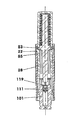
図5のように、バネフック(42)の上方端で、ハウジング(10)中に配列された状態で、それが例えば溝中に締め付けられてある穿孔された誘導ワッシャー(18)がある。必要ならば、それはまたこの点でハウジング(10)に接着される。誘導ワッシャー(18)は、シリンダ−ピストンユニット(100)のピストン(111)の前においてピストン・スライド(76)を中心揃えする。 As shown in FIG. 5, at the upper end of the spring hook (42), there is a perforated guide washer (18) that is clamped in, for example, a groove, arranged in the housing (10). If necessary, it is also glued to the housing (10) at this point. The induction washer (18) centers the piston slide (76) in front of the piston (111) of the cylinder-piston unit (100).
本明細書において示されたハウジング(10)を用いて、圧縮棒(21)は、特別な後ろグリップ側面(25)を持つカム(22)を有する。圧縮棒(21)が変形されると、これらの後ろグリップ側面(25)は、少なくともほぼ中心線(5)と直交する面内に横たわる。注射器が引き金を引かれると、それに従ってそれが端(85)に亘って急激にラッチを下ろす。引き金を引かれた後、それらも作動エレメント(82)の戻り側面(84)上にしっかりとラッチを下ろされて置かれている。 With the housing (10) shown here, the compression rod (21) has a cam (22) with a special rear grip side (25). When the compression rod (21) is deformed, these rear grip sides (25) lie at least in a plane perpendicular to the center line (5). When the syringe is triggered, it suddenly unlatches over the end (85) accordingly. After being triggered, they are also placed securely latched on the return side (84) of the actuating element (82).
バネ荷重エレメント(50)、必要な場合ピストン板及び例えば入手可能な圧縮棒(21)のベアリングローラーを除いて、先に述べられた使い捨て注射器の全ての部分はプラスチック又はプラスチック状又はゴム状の材料で作られる。 Except for the spring-loaded element (50), if necessary the piston plate and the bearing roller of the compression rod (21) available for example, all parts of the disposable syringe mentioned above are made of plastic or plastic-like or rubber-like material Made with.
1 注射溶液;薬物
5 注射器の中心線、長手方向
6 (82)の動きの作動方向、下方向の動きの方向矢印
8 ロックされる位置
9 作動位置、トリガ位置
10 ハウジング、一体物
13 外側面、シリンダ状
16 隆起、レンズ状
18 ガイドワッシャー
21 圧縮棒
22 カム
23 支持面
24 接触面
25 後ろグリップフランク
28 屈曲ビーム
31 シェル領域
33 開口部
38 孔
39 床
41 シリンダ−ピストンユニットのための固定領域
42 バネフック
43 後方グリップ
50 バネ荷重エレメント、ねじ式の圧縮バネ、バネエネルギ貯蔵部
52 (21)上のバネ荷重エレメント
54 バネフック、短い
55 戻り止めカム
56 (82)の環状溝
57 (82)の溝
58 (82)の前端
59 (82)の内壁
60 ピストン−作動プランジャ
62 パイロットピン
73 プランジャ・ディスク
74 襟面、平面状
75 襟面、円錐状
76 ピストン・スライド
77 ピストン・スライド前端、円錐状
79 ワッシャー
80 作動ユニット
81 作動キャップ
82 作動エレメント
83 広くなった領域
84 帰りフランク
85 縁、鋭い縁
86 キャップ床
87 ラッチ・タブ
88 タブ付きノッチ
90 オリジナルファスナー、帯飾り、保持エレメント
91 接着ラベル
92 (91)の主部分
93 (91)のキャップ部
94 切り取り帯飾り
95 切取りタブ
96 ミシン目、所定の破壊点
100 シリンダ−ピストンユニット
101 シリンダ
102 ラッチ・リブ
103 前端
104 接着リング
106 孔、ノズル
107 前端における窪み
108 シリンダ状床
111 ピストン
112 環状溝
114 密封リング、シール
119 密封フィルム
120 密封キャップ、接着剤シール
121 前端、上部
122 接触リンク
123 グリップチューブ
124 構造体、溝加工
125 ポットエリア
126 窓、両側
127 中空ストッパー
128 足
130 押しボタン安全装置、保持エレメント
131 爪
132 爪ノブ
133 爪ボルト
134 ブロック襟
135 ウエスト
136 戻り止めリンク
DESCRIPTION OF SYMBOLS 1 Injection solution; Drug 5 Syringe centerline, Longitudinal direction 6 (82) Movement direction of movement, Downward movement direction arrow 8 Locked position 9 Operation position, Trigger position 10 Housing, Integral body 13 Cylinder 16 Bump, lens 18 Guide washer 21 Compression rod 22 Cam 23 Support surface 24 Contact surface 25
Claims (10)
−そこでハウジング(10)が、各自由端の領域において少なくとも一つの支持面(23)を有する少なくとも一つの圧縮棒(21)を有し、
−そこでピストン−作動プランジャ(60)がプランジャ・ディスク(73)を有する支持面(23)上に載り、
−そこでピストン−作動プランジャ(60)が、バネ荷重エレメント(50)から背けたその前端上に、少なくとも一定のエリアで平らな楔状の面、又は一定のエリアで単一切頭円錐状面(74、75)を有し、該面が圧縮棒(21)の支持面(23)と接触しており、
−そこで圧縮棒(21)のロックする位置が、ロックされる位置(8)に位置する作動エレメント(82)によって固定され、
−そこでハウジング(10)の下方が作動エレメント(82)によって取り囲まれ、作動エレメント(82)がハウジング(10)の外側面(13)上で長さ方向に動くようになっており、作動エレメント(82)が、ロックされる位置(8)を有し、そこで作動エレメントが密封キャップ(120)上で確実に載り、
−そこで密封キャップ(120)が、シリンダ−ピストンユニット(100)のシリンダー(101)の下方領域を囲み、そして
−そこで作動エレメント(82)が、トリガ位置(9)を有し、ピストン−作動プランジャ(60)が開放された場合圧縮棒(21)の横方向への後退を生じさせる、
ことを特徴とする使い捨て注射器。 At least one mechanical spring energy reservoir, at least one cylinder-piston unit (100) for charging active ingredients, at least one piston-actuating plunger (60), and at least one housing (10) One actuating unit (80) is arranged, in which the spring energy store (50) includes at least one prestressed spring load element, and where at least a part of the piston-actuated plunger (60) is a spring energy store ( 50) and the piston (111) of the cylinder-piston unit (100),
The housing (10) has at least one compression rod (21) with at least one support surface (23) in the region of each free end;
The piston-actuated plunger (60) then rests on the support surface (23) with the plunger disc (73);
A piston-actuated plunger (60) is placed on its front end facing away from the spring-loaded element (50), at least in a certain area with a flat wedge-shaped surface or in a certain area with a single frustoconical surface (74, 75), the surface is in contact with the support surface (23) of the compression rod (21),
The locking position of the compression rod (21) is then fixed by the actuating element (82) located in the locked position (8);
The lower part of the housing (10) is then surrounded by the actuating element (82) so that the actuating element (82) moves longitudinally on the outer surface (13) of the housing (10) 82) has a locked position (8) where the actuating element rests securely on the sealing cap (120),
A sealing cap (120) surrounds the lower region of the cylinder (101) of the cylinder-piston unit (100), and-the actuating element (82) has a trigger position (9), and the piston-actuating plunger Causing the compression rod (21) to retreat laterally when (60) is opened,
A disposable syringe characterized by that.
Applications Claiming Priority (3)
| Application Number | Priority Date | Filing Date | Title |
|---|---|---|---|
| DE102007031714A DE102007031714A1 (en) | 2007-07-06 | 2007-07-06 | Disposable injector with at least one push rod and a cap |
| DE102007031714.1 | 2007-07-06 | ||
| PCT/EP2008/004949 WO2009006986A1 (en) | 2007-07-06 | 2008-06-19 | Disposable injector with at least one compression bar and a closure cap |
Publications (3)
| Publication Number | Publication Date |
|---|---|
| JP2010532185A JP2010532185A (en) | 2010-10-07 |
| JP2010532185A5 true JP2010532185A5 (en) | 2014-04-10 |
| JP5524831B2 JP5524831B2 (en) | 2014-06-18 |
Family
ID=39709468
Family Applications (1)
| Application Number | Title | Priority Date | Filing Date |
|---|---|---|---|
| JP2010513727A Active JP5524831B2 (en) | 2007-07-06 | 2008-06-19 | Disposable syringe having at least one compression rod and a sealing cap |
Country Status (17)
| Country | Link |
|---|---|
| US (1) | US8075515B2 (en) |
| EP (1) | EP2162172B1 (en) |
| JP (1) | JP5524831B2 (en) |
| KR (1) | KR20100041739A (en) |
| CN (1) | CN101678178B (en) |
| AR (1) | AR067392A1 (en) |
| AU (1) | AU2008274626B2 (en) |
| BR (1) | BRPI0813782A2 (en) |
| CA (1) | CA2692567A1 (en) |
| DE (1) | DE102007031714A1 (en) |
| ES (1) | ES2685447T3 (en) |
| HK (1) | HK1138525A1 (en) |
| IL (1) | IL202956A (en) |
| RU (1) | RU2487729C2 (en) |
| TW (1) | TW200920428A (en) |
| WO (1) | WO2009006986A1 (en) |
| ZA (1) | ZA200907120B (en) |
Families Citing this family (13)
| Publication number | Priority date | Publication date | Assignee | Title |
|---|---|---|---|---|
| DE102008003103A1 (en) * | 2008-01-01 | 2009-07-02 | Lts Lohmann Therapie-Systeme Ag | Disposable injector with two-piston two-chamber system |
| WO2011039231A1 (en) * | 2009-09-30 | 2011-04-07 | Sanofi-Aventis Deutschland Gmbh | Drug delivery device |
| EP2438941A1 (en) * | 2010-10-08 | 2012-04-11 | Sanofi-Aventis Deutschland GmbH | Auto injector with a torsion spring |
| CN102188762A (en) * | 2011-03-14 | 2011-09-21 | 张亚根 | Disposable safe injection pump |
| US9060773B2 (en) | 2011-12-16 | 2015-06-23 | Covidien Lp | Occlusive implant delivery devices and associated methods |
| US8834449B2 (en) | 2012-01-23 | 2014-09-16 | Ikomed Technologies, Inc. | Mixing syringe |
| US9751056B2 (en) | 2012-01-23 | 2017-09-05 | Merit Medical Systems, Inc. | Mixing syringe |
| US20150173661A1 (en) * | 2012-07-27 | 2015-06-25 | Abbott Diabetes Care, Inc. | Medical Device Applicators |
| GB2511317A (en) * | 2013-02-27 | 2014-09-03 | Owen Mumford Ltd | Automatic injection device |
| WO2016177390A1 (en) | 2015-05-04 | 2016-11-10 | Lts Lohmann Therapie-Systeme Ag | Disposable injector having a sound-proofing layer |
| FR3038229B1 (en) * | 2015-06-30 | 2017-07-28 | Crossject | NEEDLE-FREE INJECTION DEVICE EQUIPPED WITH AN IMPROVED PERCUSSION DEVICE |
| GB201819059D0 (en) * | 2018-11-22 | 2019-01-09 | Enesi Pharma Ltd | Single-use cassette assembly |
| DE102018129618A1 (en) * | 2018-11-23 | 2020-05-28 | Sfm Medical Devices Gmbh | Device for depositing an element with a cannula |
Family Cites Families (17)
| Publication number | Priority date | Publication date | Assignee | Title |
|---|---|---|---|---|
| US3556100A (en) * | 1968-08-02 | 1971-01-19 | Ampoules Inc | Ampoule applicator |
| DE1957833A1 (en) * | 1968-11-21 | 1970-07-02 | Maurice Steiner | Injection syringe, especially injection syringe handled by the patient himself |
| US4227528A (en) * | 1978-12-26 | 1980-10-14 | Wardlaw Stephen C | Automatic disposable hypodermic syringe |
| US4378015A (en) * | 1981-12-21 | 1983-03-29 | Wardlaw Stephen C | Automatic injecting syringe |
| DE3644984A1 (en) | 1986-07-01 | 1988-07-07 | Eberhardt Schlueter | Cartridge or ampoule for an injection device and automatic injection device |
| WO1994021316A1 (en) * | 1993-03-24 | 1994-09-29 | Owen Mumford Limited | Improvements relating to injection devices |
| US5891086A (en) * | 1993-07-31 | 1999-04-06 | Weston Medical Limited | Needle-less injector |
| RU2181057C2 (en) * | 1998-05-05 | 2002-04-10 | Государственный научно-исследовательский испытательный институт военной медицины | Automated injector device |
| DE19821933C1 (en) * | 1998-05-15 | 1999-11-11 | Disetronic Licensing Ag | Device for administering an injectable product |
| US6428528B2 (en) * | 1998-08-11 | 2002-08-06 | Antares Pharma, Inc. | Needle assisted jet injector |
| US6517517B1 (en) * | 2000-06-08 | 2003-02-11 | Mayo Foundation For Medical Education And Research | Automated injection device for administration of liquid medicament |
| JP4413772B2 (en) * | 2002-05-02 | 2010-02-10 | シラグ・ゲーエムベーハー・インターナショナル | Injection device |
| US6979316B1 (en) * | 2002-05-23 | 2005-12-27 | Seedlings Life Science Ventures Llc | Apparatus and method for rapid auto-injection of medication |
| DE10351594A1 (en) * | 2003-11-05 | 2005-06-16 | Tecpharma Licensing Ag | Device for the administration of an injectable product |
| JP4610567B2 (en) * | 2003-12-05 | 2011-01-12 | ゾゲニクス インコーポレーティッド | Needleless syringe delivery preparation device |
| JP4507671B2 (en) * | 2004-03-31 | 2010-07-21 | パナソニック株式会社 | Medical dosing device |
| DE102005062206B3 (en) * | 2005-12-24 | 2006-12-14 | Lts Lohmann Therapie-Systeme Ag | Disposable injection syringe has comprises piston and cylinder unit filled with active material and spring unit comprising coil spring held in compressed state by band which is cut before syringe is used by blade at its top |
-
2007
- 2007-07-06 DE DE102007031714A patent/DE102007031714A1/en not_active Withdrawn
-
2008
- 2008-06-19 CN CN2008800191853A patent/CN101678178B/en not_active Expired - Fee Related
- 2008-06-19 KR KR1020107000154A patent/KR20100041739A/en not_active Application Discontinuation
- 2008-06-19 RU RU2010103893/14A patent/RU2487729C2/en not_active IP Right Cessation
- 2008-06-19 WO PCT/EP2008/004949 patent/WO2009006986A1/en active Application Filing
- 2008-06-19 AU AU2008274626A patent/AU2008274626B2/en not_active Ceased
- 2008-06-19 CA CA 2692567 patent/CA2692567A1/en not_active Abandoned
- 2008-06-19 ES ES08773533.8T patent/ES2685447T3/en active Active
- 2008-06-19 JP JP2010513727A patent/JP5524831B2/en active Active
- 2008-06-19 BR BRPI0813782A patent/BRPI0813782A2/en not_active IP Right Cessation
- 2008-06-19 EP EP08773533.8A patent/EP2162172B1/en not_active Not-in-force
- 2008-07-01 AR ARP080102847A patent/AR067392A1/en not_active Application Discontinuation
- 2008-07-03 TW TW097125093A patent/TW200920428A/en unknown
-
2009
- 2009-10-13 ZA ZA200907120A patent/ZA200907120B/en unknown
- 2009-11-24 US US12/592,380 patent/US8075515B2/en not_active Expired - Fee Related
- 2009-12-24 IL IL202956A patent/IL202956A/en not_active IP Right Cessation
-
2010
- 2010-04-28 HK HK10104132.9A patent/HK1138525A1/en not_active IP Right Cessation
Similar Documents
| Publication | Publication Date | Title |
|---|---|---|
| JP2010532185A5 (en) | ||
| JP5524831B2 (en) | Disposable syringe having at least one compression rod and a sealing cap | |
| RU2114559C1 (en) | One-time puncturing device | |
| JP5503536B2 (en) | Disposable syringe having at least one support rod | |
| RU2493883C2 (en) | Disposable injector | |
| US8262604B2 (en) | Single-use injector with at least one draw hook | |
| KR101630894B1 (en) | Single-use injector having a flexurally elastic housing | |
| JP5620274B2 (en) | Disposable syringe with dual piston dual chamber system | |
| US8287490B2 (en) | Disposable injector provided with high injector safety | |
| AU2006331121B2 (en) | One-way injector with continuously charged spring energy store | |
| JP5523314B2 (en) | Disposable syringe having at least one elongated hook | |
| JP2011508640A (en) | Disposable syringe with manually actuated piston and twin chamber system | |
| JP5579185B2 (en) | Syringe with sterile components and dual chamber system | |
| JP5176396B2 (en) | Lancet assembly | |
| US3368559A (en) | Hypodermic injector with safely held release means | |
| CN218187476U (en) | Puncture-proof protection device |