RU2487729C2 - Disposable injector with at least one rod and barrier cap - Google Patents
Disposable injector with at least one rod and barrier cap Download PDFInfo
- Publication number
- RU2487729C2 RU2487729C2 RU2010103893/14A RU2010103893A RU2487729C2 RU 2487729 C2 RU2487729 C2 RU 2487729C2 RU 2010103893/14 A RU2010103893/14 A RU 2010103893/14A RU 2010103893 A RU2010103893 A RU 2010103893A RU 2487729 C2 RU2487729 C2 RU 2487729C2
- Authority
- RU
- Russia
- Prior art keywords
- piston
- cylinder
- disposable injector
- injector according
- spring
- Prior art date
Links
- 230000004888 barrier function Effects 0.000 title abstract 5
- 239000013543 active substance Substances 0.000 claims abstract description 3
- 238000006073 displacement reaction Methods 0.000 claims abstract 2
- 239000000853 adhesive Substances 0.000 claims description 14
- 230000001070 adhesive effect Effects 0.000 claims description 14
- 238000005452 bending Methods 0.000 claims description 7
- 230000007246 mechanism Effects 0.000 claims description 2
- 238000004146 energy storage Methods 0.000 claims 1
- 239000007924 injection Substances 0.000 abstract description 12
- 238000002347 injection Methods 0.000 abstract description 12
- 239000007858 starting material Substances 0.000 abstract description 10
- 239000003814 drug Substances 0.000 abstract description 3
- 230000036512 infertility Effects 0.000 abstract 1
- 239000000126 substance Substances 0.000 abstract 1
- 238000007789 sealing Methods 0.000 description 7
- 239000011521 glass Substances 0.000 description 5
- 230000000903 blocking effect Effects 0.000 description 4
- 230000006835 compression Effects 0.000 description 4
- 238000007906 compression Methods 0.000 description 4
- 239000000463 material Substances 0.000 description 3
- 230000009471 action Effects 0.000 description 2
- 229940079593 drug Drugs 0.000 description 2
- 238000000034 method Methods 0.000 description 2
- 239000004033 plastic Substances 0.000 description 2
- 230000008569 process Effects 0.000 description 2
- 239000007787 solid Substances 0.000 description 2
- 235000014676 Phragmites communis Nutrition 0.000 description 1
- 239000004952 Polyamide Substances 0.000 description 1
- 239000012790 adhesive layer Substances 0.000 description 1
- MTAZNLWOLGHBHU-UHFFFAOYSA-N butadiene-styrene rubber Chemical compound C=CC=C.C=CC1=CC=CC=C1 MTAZNLWOLGHBHU-UHFFFAOYSA-N 0.000 description 1
- 239000000919 ceramic Substances 0.000 description 1
- 230000036461 convulsion Effects 0.000 description 1
- 230000001419 dependent effect Effects 0.000 description 1
- 238000010586 diagram Methods 0.000 description 1
- 239000011152 fibreglass Substances 0.000 description 1
- 239000003292 glue Substances 0.000 description 1
- 238000009434 installation Methods 0.000 description 1
- 239000007788 liquid Substances 0.000 description 1
- 230000005923 long-lasting effect Effects 0.000 description 1
- 239000002184 metal Substances 0.000 description 1
- 238000000465 moulding Methods 0.000 description 1
- 229920002647 polyamide Polymers 0.000 description 1
- 238000003825 pressing Methods 0.000 description 1
- 238000005096 rolling process Methods 0.000 description 1
- 239000002356 single layer Substances 0.000 description 1
- 239000000243 solution Substances 0.000 description 1
- 229920002994 synthetic fiber Polymers 0.000 description 1
- 210000003813 thumb Anatomy 0.000 description 1
- 210000002105 tongue Anatomy 0.000 description 1
- 230000007704 transition Effects 0.000 description 1
Images


Classifications
-
- A—HUMAN NECESSITIES
- A61—MEDICAL OR VETERINARY SCIENCE; HYGIENE
- A61M—DEVICES FOR INTRODUCING MEDIA INTO, OR ONTO, THE BODY; DEVICES FOR TRANSDUCING BODY MEDIA OR FOR TAKING MEDIA FROM THE BODY; DEVICES FOR PRODUCING OR ENDING SLEEP OR STUPOR
- A61M5/00—Devices for bringing media into the body in a subcutaneous, intra-vascular or intramuscular way; Accessories therefor, e.g. filling or cleaning devices, arm-rests
- A61M5/178—Syringes
- A61M5/30—Syringes for injection by jet action, without needle, e.g. for use with replaceable ampoules or carpules
-
- A—HUMAN NECESSITIES
- A61—MEDICAL OR VETERINARY SCIENCE; HYGIENE
- A61M—DEVICES FOR INTRODUCING MEDIA INTO, OR ONTO, THE BODY; DEVICES FOR TRANSDUCING BODY MEDIA OR FOR TAKING MEDIA FROM THE BODY; DEVICES FOR PRODUCING OR ENDING SLEEP OR STUPOR
- A61M5/00—Devices for bringing media into the body in a subcutaneous, intra-vascular or intramuscular way; Accessories therefor, e.g. filling or cleaning devices, arm-rests
- A61M5/178—Syringes
- A61M5/20—Automatic syringes, e.g. with automatically actuated piston rod, with automatic needle injection, filling automatically
- A61M2005/2006—Having specific accessories
- A61M2005/2013—Having specific accessories triggering of discharging means by contact of injector with patient body
-
- A—HUMAN NECESSITIES
- A61—MEDICAL OR VETERINARY SCIENCE; HYGIENE
- A61M—DEVICES FOR INTRODUCING MEDIA INTO, OR ONTO, THE BODY; DEVICES FOR TRANSDUCING BODY MEDIA OR FOR TAKING MEDIA FROM THE BODY; DEVICES FOR PRODUCING OR ENDING SLEEP OR STUPOR
- A61M5/00—Devices for bringing media into the body in a subcutaneous, intra-vascular or intramuscular way; Accessories therefor, e.g. filling or cleaning devices, arm-rests
- A61M5/178—Syringes
- A61M5/20—Automatic syringes, e.g. with automatically actuated piston rod, with automatic needle injection, filling automatically
- A61M2005/2073—Automatic syringes, e.g. with automatically actuated piston rod, with automatic needle injection, filling automatically preventing premature release, e.g. by making use of a safety lock
-
- A—HUMAN NECESSITIES
- A61—MEDICAL OR VETERINARY SCIENCE; HYGIENE
- A61M—DEVICES FOR INTRODUCING MEDIA INTO, OR ONTO, THE BODY; DEVICES FOR TRANSDUCING BODY MEDIA OR FOR TAKING MEDIA FROM THE BODY; DEVICES FOR PRODUCING OR ENDING SLEEP OR STUPOR
- A61M5/00—Devices for bringing media into the body in a subcutaneous, intra-vascular or intramuscular way; Accessories therefor, e.g. filling or cleaning devices, arm-rests
- A61M5/178—Syringes
- A61M5/20—Automatic syringes, e.g. with automatically actuated piston rod, with automatic needle injection, filling automatically
- A61M5/2033—Spring-loaded one-shot injectors with or without automatic needle insertion
-
- A—HUMAN NECESSITIES
- A61—MEDICAL OR VETERINARY SCIENCE; HYGIENE
- A61M—DEVICES FOR INTRODUCING MEDIA INTO, OR ONTO, THE BODY; DEVICES FOR TRANSDUCING BODY MEDIA OR FOR TAKING MEDIA FROM THE BODY; DEVICES FOR PRODUCING OR ENDING SLEEP OR STUPOR
- A61M5/00—Devices for bringing media into the body in a subcutaneous, intra-vascular or intramuscular way; Accessories therefor, e.g. filling or cleaning devices, arm-rests
- A61M5/178—Syringes
- A61M5/31—Details
- A61M5/32—Needles; Details of needles pertaining to their connection with syringe or hub; Accessories for bringing the needle into, or holding the needle on, the body; Devices for protection of needles
- A61M5/3202—Devices for protection of the needle before use, e.g. caps
Abstract
Description
Изобретение относится к одноразовому инъектору с корпусом, в котором или на котором - соответственно, по меньшей мере, местами - расположены, по меньшей мере, один механический пружинный энергоаккумулятор, по крайней мере, один - по меньшей мере, периодически заполняемый активным веществом - блок цилиндр-поршень, по меньшей мере, один плунжер управления поршнем и, по меньшей мере, один пусковой блок, причем пружинный энергоаккумулятор включает, по меньшей мере, один предварительно напряженный пружинный элемент и причем, по меньшей мере, часть плунжера управления поршнем расположена между знергоаккумулятором и поршнем блока цилиндр-поршень.The invention relates to a disposable injector with a housing in which or on which, respectively, at least in places, are located at least one mechanical spring energy accumulator, at least one - at least periodically filled with active substance - cylinder block a piston, at least one piston control plunger and at least one starting block, wherein the spring energy accumulator includes at least one prestressed spring element and, at least, frequently the control piston is located between the plunger and the piston znergoakkumulyatorom cylinder-piston unit.
Из заявки на патент Германии DE 3644984 A1 среди прочего известно подобного рода устройство для инъекций. Оно имеет предварительно напряженный пружиной плунжер управления поршнем, задняя плунжерная штанга которого на своем свободном конце имеет упругие тяговые крюки. Тяговые крюки удерживают с геометрическим замыканием плунжер управления поршнем на кромке корпуса инъектора. Для этого они имеют только небольшую опорную поверхность на корпусе. Для приведения в действие инъектора тяговые крюки смещаются с удерживающей их кромки. В результате предварительно нагруженный пружиной плунжер управления поршнем «выстреливается» вперед, чтобы осуществить инъекцию.From German patent application DE 3644984 A1, among other things, such an injection device is known. It has a piston control piston pre-stressed by a spring, the rear plunger rod of which has elastic pull hooks at its free end. Traction hooks hold with a geometric closure the piston for controlling the piston on the edge of the injector body. To do this, they have only a small bearing surface on the housing. To actuate the injector, the traction hooks are displaced from the edge holding them. As a result, the piston control plunger preloaded by the spring “shoots” forward to inject.
Документы WO 2005/044344 A1 и EP 1366419 A1 описывают игловой инъектор с устройством защить иглы, плунжер управления поршнем которого представляет собой тяговый стержень, соответственно тяговую гильзу, плунжер управления поршнем которого нагружаем на растяжение приводящей при инъекции поршень нажимной пружины, опирается рсположенные со стороны корпуса опорные элменты. При этом опорные элементы прилегают к нименьшему диаметру плунжера управления поршнем, вследствие чего в контактной зоне имеется особенное поверхностное прижимание.Documents WO 2005/044344 A1 and EP 1366419 A1 describe a needle injector with a needle shield device, the piston control plunger of which is a pull rod, respectively a pull sleeve, the piston control plunger of which is loaded by tensile pressure spring which injects the piston and relies on the housing side supporting elements. In this case, the support elements are adjacent to the smallest diameter of the piston for controlling the piston, as a result of which there is a special surface pressing in the contact zone.
Задача изобретения заключается в разработке одноразового инъектора модульной конструкции, который при небольших габаритах имеет только небольшое количество конструктивных элементов, и при простом обращении обеспечивают надежное хранение и функционирование.The objective of the invention is to develop a disposable injector of a modular design, which, with small dimensions, has only a small number of structural elements, and with simple handling provide reliable storage and operation.
Поставленная задача решается за счет того, что корпус имеет по меньшей мере один нажимной крюк, который имеет в зоне своего свободного конца по меньшей мере одну опорную поверхность, причем к опорной поверхности прилегает плунжен управления поршнем своим плунжерным диском, при этом блокирующее положение нажимного крюка обеспечено позиционированным в блокировочном положении пусковым элементом, причем пусковой элемент имеет блокировочное положение, в котором он прилегает с предохранением к затворному колпачку, и пусковой элемент имеет пусковое положение, в котором обеспечивается боковое отклонение нажимного крюка при отпускании плунжера управления поршнем.The problem is solved due to the fact that the housing has at least one pressure hook, which has at least one abutment surface in the region of its free end, and the plunger controlling the piston with its plunger disk is adjacent to the abutment surface, while the locking position of the pressure hook is ensured positioned in the locking position by the trigger element, the trigger element has a locking position in which it is attached with protection to the bolt cap, and the trigger element has starting position, which provides lateral deviation of the pressure hook when releasing the piston control piston.
Изобретением представляется не имеющий иглы одноразовый инъектор, плунжен управления поршнем которого при процессе запуска одноразового инъектора освобождается. Для этого для предварительного напряжения и удержания пружинного аккумулятора плунжер управления поршнем удерживается с геометрическим и кинематическим замыканием расположенным на корпусе или интегрированным в корпусе нажимным стержнем. Нажимной стержень или опорные стержни удерживаются и предохраняются пусковым элементом вплоть до употребления одноразового инъектора в его блокировочном положении и посредством запорного колпачка, который одновременно стерильно закрывает блок цилиндр-поршень. Для запуска инъектора освобождается опорный стержень или опорные стержни, так что плунжер управления поршнем - под действием пружинного аккумулятора - может двигаться по меньшей мере приблизительно параллельно средней линии одноразового инъектора.The invention is a needle-less disposable injector, the piston of the piston of which is released during the start-up of the disposable injector. To do this, to pre-tension and hold the spring battery, the piston control piston is held with a geometric and kinematic closure located on the housing or integrated in the housing by a push rod. The pressure rod or support rods are held and secured by the trigger until the use of the disposable injector in its blocking position and by means of a locking cap that at the same time sterically closes the cylinder-piston block. To start the injector, the support rod or support rods are released so that the piston control piston - under the action of the spring accumulator - can move at least approximately parallel to the midline of the disposable injector.
Дальнейшие подробности изобретения вытекают из зависимых пунктов формулы и из нижеследующего описания схематически представленных примеров выполнения.Further details of the invention arise from the dependent claims and from the following description of schematically presented exemplary embodiments.
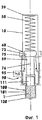
Фиг.1 одноразовый инъектор с двумя нажимными стержнями и конической связующей поверхностью;Figure 1 disposable injector with two pressure rods and a conical bonding surface;
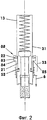
Фиг.2 как на фиг.1, однако со снятым предохранением и приведенный в действие;Figure 2 as in figure 1, however, with the protection removed and powered;
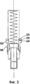
Фиг.3 как на фиг.2, однако после выпуска медикамента;Figure 3 as in figure 2, however, after the release of the medication;
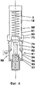
Фиг.4 одноразовый инъекторо с двумя опорными стержнями и плоской торцевой поверхностью;Figure 4 disposable injector with two supporting rods and a flat end surface;
Фиг.5 одноразовый инъектор с двумя деформированными в положении блокировки стержнями и дополнительно направляемым плунжером управления поршнем;5, a disposable injector with two rods deformed in the locked position and an additionally directed piston control plunger;
Фиг.6 как на фиг.5, однако со снятым предохранением и приведенный в действие (фиктивное состояние);Fig.6 as in Fig.5, however, with the protection removed and activated (fictitious state);
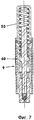
Фиг.7 как на фиг.6, однако с опорожненным цилиндром;Fig.7 as in Fig.6, however, with the cylinder empty;
Фиг.8 диметрический фиг.5;Fig.8 dimetric figure 5;
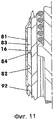
Фиг.9 одноразовый инъектор с двумя деформированными в положении блокировки нажимными стержнями и дополнительным предохранением;Fig. 9 a disposable injector with two pressure rods deformed in the locked position and additional protection;
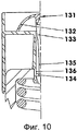
Фиг.10 увеличение вырезов по фиг.9;Figure 10 is an increase in the cutouts of Figure 9;
Фиг.11 увеличение вырезов по фиг.9, однако со смещением на 90 угловых градусов;11, an increase in the cutouts of FIG. 9, however with an offset of 90 degrees;
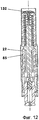
Фиг.12 как на фиг.9, однако удалением бандероли снят с предохранения и приведен в действие (фиктивное состояние);Fig. 12 as in Fig. 9, however, by removing the parcel, it has been deactivated and activated (fictitious state);
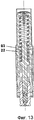
Фиг.13 как на фиг.12, однако с опорожненным цилиндром;Fig. 13 as in Fig. 12, however, with the cylinder empty;
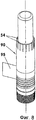
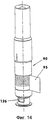
Фиг.14 диметрический вид по фиг.9.Fig.14 is a dimetric view of Fig.9.
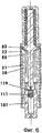
На фигурах 1 до 3 показаны упрощенные принципиальные схемы одного типа одноразового инъектора с имеющим длительную зарядку пружинным энергоаккумулятором в трех различных состояниях приведения в действие. Показанный одноразовый инъектор состоит из корпуса (10), предварительно заполненного раствором для инъекций блока (100) цилиндр-поршень, плунжера (60) управления поршнем, и нажимной винтовой пружины (50) в качестве пружинного энергоаккумулятора. К тому же на корпусе (10) расположены пусковой элемент (82) и предохранительный элемент (90). Блок (100) цилиндр-поршень спереди закрыт запорным колпачком (120).Figures 1 to 3 show simplified schematic diagrams of one type of disposable injector with a long-lasting spring-loaded energy accumulator in three different actuation states. The disposable injector shown consists of a housing (10) pre-filled with an injection solution for a cylinder-piston block (100), a piston control piston (60), and a pressure coil spring (50) as a spring energy accumulator. In addition, a trigger element (82) and a safety element (90) are located on the housing (10). The cylinder-piston block (100) is closed in front by a locking cap (120).
Корпус (10) представляет собой имеющий цилиндрическую форму, открытый снизу полый корпус с расположенным вверху дном (39). В средней области, области оболочки (31) корпус (10) имеет, например, два противолежащих друг другу, имеющих вид окошек проема (33). На соответственно нижнем краю проема (33), см. фиг.2, правую сторону инъектора, шарнирно установлен соответственно опорный стержень (21).The casing (10) is a hollow casing having a cylindrical shape, open from the bottom with a bottom located at the top (39). In the middle region, the region of the shell (31), the housing (10) has, for example, two opposite to each other, having the form of the windows of the opening (33). On the correspondingly lower edge of the opening (33), see FIG. 2, the right side of the injector, the support rod (21) is pivotally mounted accordingly.
Опорные стержни (21) расположены здесь как пример в поворотных шарнирах и опираются на корпус (10) через пружинные элементы (52). Пружинные элементы (52) давят на опорные стержни (21) по меньшей мере приблизительно радиально наружу против пускового элемента (82), см. фиг.1 до 3. Там они прилегают через кулачки (22) к пусковому элементу (82). Кулачки (22) могут при этом лежать, например, 5 до 20 миллиметров под свободным верхним концом опорных стержней (21). Если опорные стержни (21) приформованы к корпусу (10), см. фиг.5 и 9, они пружинят в качестве эластичных балок (28) наружу.The support rods (21) are located here as an example in the swivel joints and are supported on the housing (10) through the spring elements (52). The spring elements (52) are pressed against the support rods (21) at least approximately radially outward against the trigger element (82), see FIGS. 1 to 3. There, they fit through the cams (22) to the trigger element (82). The cams (22) can then lie, for example, 5 to 20 millimeters under the free upper end of the support rods (21). If the support rods (21) are molded to the housing (10), see FIGS. 5 and 9, they spring outward as elastic beams (28).
Оба нагруженных на давление опорных стержня (21) удерживают плунжер (60) управления поршнем на его плунжерном диске (73) в своем предварительно напряженном положении, см. фиг.1. Для этого опорные стержни (21) опираются своими опорными поверхностями (23) на плунжерный диск (73). Величина контактной поверхности между опорной поверхностью (23) и соответствующим местом на плунжерном диске (73) составляет в диапазоне от 2 до 20 мм2.Both pressure-loaded support rods (21) hold the piston control plunger (60) on its plunger disk (73) in their pre-stressed position, see FIG. 1. For this, the support rods (21) are supported by their support surfaces (23) on the plunger disk (73). The size of the contact surface between the supporting surface (23) and the corresponding place on the plunger disk (73) is in the range from 2 to 20 mm 2 .
На удаленной от средней линии (5) стороне каждый напорный стержень (21) имеет на своем кулачке (22) опорную поверхность (24).On the side remote from the midline (5), each pressure rod (21) has a bearing surface (24) on its cam (22).
В нижней зоне корпуса (10) находится удерживающий элемент для крепления блока (100) цилиндр-поршень.In the lower zone of the housing (10) there is a holding element for fastening the cylinder-piston block (100).
Блок (100) цилиндр-поршень состоит в примере выполнения из заполненного инъекционной жидкостью прозрачного цилиндра (101), в котором сидит в задней позиции поршень (111). Поверх поршня (111) в корпусе (10) расположен плунжер (60) управления поршнем таким образом, что он правда не касается поршня, однако своим нижним концом сбоку направляется в верхней зоне цилиндра (101).The cylinder-piston block (100) consists in an example of a transparent cylinder (101) filled with injection liquid, in which the piston (111) sits in the rear position. On top of the piston (111) in the housing (10) is located the piston (60) for controlling the piston so that it does not really touch the piston, however, its lower end is directed to the upper zone of the cylinder (101) from its side.
Согласно фигуре 1 нижняя половина корпуса (10) окружена гильзеобразным пусковым элементом (82). Пусковой элемент (82) установлен с возможностью линейного перемещения на радиальной наружной поверхности корпуса (10). Он имеет в верхней области на высоте кулачков (22) окружное расширение (83). Вместо этого расширения (83) при не вращательно-симметричном пусковом элементе (82) на каждый опорный стержень (21) могут иметься частичные расширения или не покрытые отверстия.According to figure 1, the lower half of the housing (10) is surrounded by a sleeve-like starting element (82). The trigger element (82) is installed with the possibility of linear movement on the radial outer surface of the housing (10). It has a circumferential extension (83) in the upper region at the height of the cams (22). Instead of this expansion (83) with a non-rotationally symmetrical starting element (82), for each support rod (21) there may be partial extensions or uncovered openings.
Расширение (83) расположено так и имеет такие размеры в отношении корпуса (10), что оно может принимать отклоняющиеся назад при процессе освобождения, выталкивающиеся наружу опорные стержни (21) с их кулачками (22). Внутренний контур расширения (83) представляет собой канал с боковой стороной (84) ниши, которая здесь представляет плоскость, нормальную к средней линии (5) инъектора. Переход между, например, цилиндрической внутренней стенкой пускового элемента (82) и боковой стороной (84) ниши выполнен, например, в виде кромки (85) с острыми краями. Согласно фигуре 1 кулачки (22) своими наружными поверхностями (24) с предохранением прилегают к внутренней стенке (59) пускового элемента (82).The extension (83) is located and has such dimensions with respect to the housing (10) that it can take support rods (21) that are deflected back during the release process and are pushed out with their cams (22). The inner contour of the expansion (83) is a channel with the side (84) of the niche, which here represents a plane normal to the midline (5) of the injector. The transition between, for example, the cylindrical inner wall of the launch element (82) and the side side (84) of the niche is made, for example, in the form of an edge (85) with sharp edges. According to figure 1, the cams (22) with their outer surfaces (24) are secured against the inner wall (59) of the trigger element (82).
Расположенный в корпусе (10) плунжер (60) управления поршнем здесь разделен на две области. Нижняя область представлена поршневым золотником (76). Его диаметр несколько меньше, чем внутренний диаметр цилиндра (101) блока (100) цилиндр-поршень. Нижняя торцевая поверхность поршневого золотника (76) воздействует непосредственно на поршень (111).The piston control piston (60) located in the housing (10) is here divided into two areas. The lower region is represented by a piston spool (76). Its diameter is slightly smaller than the inner diameter of the cylinder (101) of the block (100) of the cylinder-piston. The lower end surface of the piston spool (76) acts directly on the piston (111).
Верхняя область, плунжерный диск (73), который представляет собой плоский, по меньшей мере, местами цилиндрический диск. наружный диаметр которого на несколько десятых миллиметра меньше внутреннего диаметра корпуса (10) в области (31) оболочки. Нижняя торцевая сторона (74) имеет расположенную вокруг поршневого золотника (76) свяязующую поверхность (75). Она имеет форму боковой поверхности усеченного конуса, чей угол при вершине составляет приблизительно от 100 до 130°, предпочтительно 120°.The upper region is a plunger disk (73), which is a flat, at least in some places cylindrical disk. the outer diameter of which is several tenths of a millimeter smaller than the inner diameter of the housing (10) in the region (31) of the shell. The lower end side (74) has a bonding surface (75) located around the piston spool (76). It has the shape of a lateral surface of a truncated cone, whose apex angle is from about 100 to 130 °, preferably 120 °.
Воображаемая вершина боковой поверхности усеченного конуса лежит на средней линии (5) в области поршневого золотника (76). Соединительная поверхность (75) может быть также сферически загнутой.The imaginary apex of the lateral surface of the truncated cone lies on the midline (5) in the area of the piston spool (76). The connecting surface (75) can also be spherically bent.
Поршневой золотник (76), разумеется, может быть выполнен в виде обособленного, отдельного от плунжерного диска (73) конструктивного элемента. При этом он направляется тогда по внутренней стенке корпуса (10).The piston spool (76), of course, can be made in the form of a separate structural element separate from the plunger disk (73). In this case, he then goes along the inner wall of the housing (10).
Между плунжерным диском (73) и лежащим вверху дном (39) корпуса (10) установлена предварительно напряженная винтовая нажимная пружина (50). Пружинное усилие передается через плунжерный диск (73) на опорные стержни (21). Благодаря наклону соединительной поверхности (75) опорные стержни (21) наподобие клинового механизма выталкиваются радиально наружу. Пусковая гильза (82) долговременно поддерживает это радиальное усилие.Between the plunger disk (73) and the bottom (39) of the housing (10) lying at the top, a prestressed helical compression spring (50) is installed. The spring force is transmitted through the plunger disk (73) to the support rods (21). Due to the inclination of the connecting surface (75), the support rods (21), like a wedge mechanism, are pushed radially outward. The starter sleeve (82) maintains this radial force for a long time.
К нижнему концу пускового элемента (82) примыкает затворный колпачок (120). Последний стерильно закрывает нижнюю часть блока (100) поршень-цилиндр. Затворный колпачок (120) расположен в нижней зоне корпуса (10). Затворный колпачок (120) и гильзообразный пусковой элемент (82) по меньшей мере по зонам окружен клеевой этикеткой (91), см. фиг.4. Клеевая этикетка (91) состоит из основной части (92), отрывной бандероли (94) и головной части (93). Отрывная бандероль (94) связана с частями (92, 93) этикетки местом отрывания (96), например, перфорацией или тонким местом материала. Отрывная бандероль (94) при этом расположена над лежащим между пусковым элементом (82) и затворным колпачком (120) монтажным швом. Она заканчивается выступающим отрывным флажочком.A closure cap (120) is adjacent to the lower end of the trigger element (82). The latter sterilely closes the lower part of the piston-cylinder block (100). The shutter cap (120) is located in the lower zone of the housing (10). The closure cap (120) and the sleeve-like trigger element (82) are surrounded by an adhesive label (91) in at least zones, see FIG. 4. The adhesive label (91) consists of the main part (92), a tear-off parcel (94) and the head part (93). A tear-off parcel (94) is connected with the parts (92, 93) of the label by a tear-off place (96), for example, by perforation or a thin spot of material. A tear-off parcel (94) is located above the mounting seam lying between the starting element (82) and the shutter cap (120). It ends with a protruding tear-off flag.
Может также применяться полноплоскостная клеевая этикетка, которая в зоне раазделяющего части (82) и (120) монтажного шва содержит прочный на отрывание тяговый орган. Тяговый орган, например, нить, пластмассовая полоска, тонкая проволока или т.п. на одной стороне выступает за этикетку. При отрывании тягового органа этикетку нацеленно отделяют в зоне монтажного шва.A full-plane adhesive label can also be used, which in the area of the separating part (82) and (120) of the mounting seam contains a tear-off pull member. Traction body, e.g. thread, plastic strip, thin wire or the like. on one side stands for the label. When tearing off the traction body, the label is deliberately separated in the area of the mounting seam.
Для снятия предохранения инъектора отрывная бандероль (94) стягивается, так что клеящее соединение между затворным колпачком (120) и пусковым элементом (82) упроздняется. Для последующего приведения в действие одноразового инъектора - после удаления затворного колпачка (120) блока (100) цилиндр-поршень - одноразовый инъектор позиционируется на месте инъекции. Тогда пусковой элемент (82) может перемещаться в направлении блока (100) цилиндр-поршень. При этом процессе пусковой элемент скользит по внешней стенке (13) корпуса (10) линейно вниз, т.е. в направлении места инъекции. Поверхности прилегания (24) нажимных стержней (21) скользят по кромке (85) и соскакивают под действием усилия пружинного элемента (50) радиально вниз, снимая предохранение, в расширение (83). Плунжер (60) управления поршнем спешит вниз без препятствий. см. фиг.3. Цилиндр (100) опорожняется.To remove the protection of the injector, the tear-off parcel (94) is pulled together so that the adhesive connection between the closure cap (120) and the trigger element (82) becomes more rigid. For the subsequent actuation of the disposable injector - after removing the shutter cap (120) of the cylinder-piston block (100) - the disposable injector is positioned at the injection site. Then the starting element (82) can move in the direction of the cylinder-piston block (100). In this process, the trigger element slides along the outer wall (13) of the housing (10) linearly downward, i.e. in the direction of the injection site. The abutment surfaces (24) of the pressure rods (21) slide along the edge (85) and jump off radially downward by the force of the spring element (50), removing the protection, into the extension (83). The piston control piston (60) hurries down without obstacles. see figure 3. The cylinder (100) is empty.
Вместо линейного скользящего движения пускового элемента (82) на корпусе (10) может быть предусмотрено винтообразное движение. В этом случае пусковой элемент (82) и корпус (10) подводятся друг к другу кулисным камнем и кулисой. В случае необходимости запуск может быть реализован чисто качательным движением между корпусом (10) и пусковым элементом (82). Ось качания была бы при этом средней линией (5).Instead of a linear sliding motion of the trigger element (82), a helical motion may be provided on the housing (10). In this case, the starting element (82) and the housing (10) are brought to each other by a rocker and a rocker. If necessary, the launch can be realized by a purely swinging movement between the housing (10) and the starting element (82). The swing axis would be the middle line (5).
На фиг.4 показан вариант с измененным пусковым блоком (80) и другим поршневым золотником (76). На пусковом элементе (82) прикреплен пусковой колпачок (81), который полностью огибает задний конец корпуса (10). При этом пусковой колпачок (81) окружает расширение (83).Figure 4 shows a variant with a modified starting block (80) and another piston spool (76). On the trigger element (82) is attached a trigger cap (81), which completely envelops the rear end of the housing (10). In this case, the starting cap (81) surrounds the extension (83).
В этом варианте связующая поверхность (75) плунжерного диска (73) выполнена плоской. Соединительная поверхность (75) ориентирована нормально к средней линии (5). Через скругленную кромку она контактирует с верхними торцевыми поверхностями опорных стержней (21). Эти торцевые поверхности выполнены клиновидными, в форме боковой поверхности усеченного конуса или сферически изогнуты. Соответственно кривизна ориентирована таким образом, что на опорные стержни (21) - как в вариантах согласно фигурам 1-3 - действует сила, направленная радиально наружу.In this embodiment, the connecting surface (75) of the plunger disk (73) is made flat. The connecting surface (75) is oriented normally to the midline (5). Through a rounded edge, it contacts the upper end surfaces of the support rods (21). These end surfaces are wedge-shaped, in the form of a lateral surface of a truncated cone or spherically bent. Accordingly, the curvature is oriented in such a way that a force directed radially outward acts on the support rods (21), as in the variants according to figures 1-3.
Далее поршневой золотник (76) имее центральную конусообразную вершину (77). Эта вершина (77) входит в соответствующую выемку поршня (111). Таким образом поршень (111) может дополнительно центрировать и направлять движущийся плунжер (60) приведения в действие поршня или его части.Further, the piston spool (76) has a central conical peak (77). This vertex (77) enters the corresponding piston groove (111). In this way, the piston (111) can further center and guide the moving plunger (60) of actuating the piston or part thereof.
На фиг.5-8 показана форма осуществления принципа, описанного на фиг.1-3. Здесь несущий конструктивный элемент представлен цельным корпусом (10). Он изготавливается, например, из усиленного стекловолокном полиамида литьем под давлением. В основном корпус имеет форму трубы и разделен на две функциональные области, это, во-первых, верхняя область (31) оболочки и, во-вторых, нижняя область (41) фиксации.Figure 5-8 shows a form of implementation of the principle described in figures 1-3. Here, the supporting structural element is represented by a solid housing (10). It is made, for example, of fiberglass reinforced polyamide die-cast. Basically, the body has the shape of a pipe and is divided into two functional areas, this is, firstly, the upper region (31) of the shell and, secondly, the lower region (41) of fixation.
В основном имеющая форму трубы область (31) оболочки закрыта вверху, например, плоским дном (39). В нижней половине области (31) оболочки находятся, сравните фиг.8 и 10, два противоположных друг другу отформованных тяговых крюка (21). Место формования тяговых крюков (21) лежит рядом над областью (41) фиксации. Для образования соответствующего опорного стержня (21) в участке (31) оболочки находится узкая, по меньшей мере, приблизительно u-образная щель, которая охватывает отдельный опорный стержень сбоку и сверху. Опорный стержень (21) имеет до 80% своей длины толщину стенки и кривизну стенки корпуса (10). Эта область кроме прочего имеет также функции нагруженной пружиной балки (28), работающей на изгиб. Она имеет серповидное поперечное сечение.Basically, the pipe-shaped region (31) of the shell is closed at the top, for example, with a flat bottom (39). In the lower half of the shell region (31), compare FIGS. 8 and 10, two opposed molded pull hooks (21). The molding location of the traction hooks (21) lies adjacent to the fixing region (41). To form the corresponding support rod (21), a narrow, at least approximately u-shaped slot is located in the section (31) of the shell, which covers a separate support rod from the side and from the top. The support rod (21) has up to 80% of its length the wall thickness and the curvature of the wall of the housing (10). This area, among other things, also has the functions of a spring-loaded beam (28) operating in bending. It has a sickle-shaped cross section.
В случае необходимости часть этой работающей на изгиб балки (28) может быть выполнена прямоугольного поперечного сечения, чтобы уменьшить возникающие при использовании изгибающие напряжения в области балки, работающей на изгиб. На фиг.6 и 7 показан опорный стержень (21) в недеформированном состоянии.If necessary, part of this bending beam (28) can be made of rectangular cross-section in order to reduce the bending stresses arising during use in the region of the bending beam. 6 and 7 show the support rod (21) in an undeformed state.
Здесь верхний свободный конец отдельного опорного стержня (21) выполнен выступающим радиально наружу кулачком (22). Последний имеет, по меньшей мере, одну опорную поверхность (23) и поверхность (24) прилегания. Согласно фиг.5 на опорную поверхность (23) своей соединительной поверхностью (75) опирается плунжерный диск (73) находящегося под нагрузкой одноходового инъектора. Опорная поверхность (23), которая здесь выполняет функцию клиновой поверхности, имеет форму боковой поверхности усеченного конуса с углом при вершине в 120°.Here, the upper free end of a separate support rod (21) is made protruding radially outwardly by a cam (22). The latter has at least one abutment surface (23) and an abutment surface (24). According to Fig. 5, a plunger disk (73) of a one-way injector under load is supported on its supporting surface (23) by its connecting surface (75). The supporting surface (23), which here functions as a wedge surface, has the shape of a lateral surface of a truncated cone with an apex angle of 120 °.
В случае необходимости опорные стержни (21) или связующая поверхность (75) имеют, по меньшей мере, в области контакта керамическую футеровку. В примере осуществления согласно фиг.5 связующая поверхность (75) усилена, например, наклеенной, разделенной по середине и имеющей форму боковой поверхности усеченного конуса подкладной шайбой (79).If necessary, the support rods (21) or the bonding surface (75) have a ceramic lining at least in the contact area. In the embodiment of FIG. 5, the bonding surface (75) is reinforced, for example, by a glued washer (79) glued, divided in the middle and having the shape of a truncated conical side surface with a washer.
Поверхность (24) прилегания кулачков недеформированных опорных стержней (21) представлена частью цилиндрической оболочки, диаметр которой, например, на от 3 до 4 мм больше наружного диаметра корпуса (10). Поверхность (24) прилегания при напряженном одноходовом устройстве для инъекций касается внутренней стенки (59) имеющего форму гильзы пускового элемента (82). При необходимости - для минимизации поверхностного прижима - поверхность (24) прилегания может иметь кривизну, которая соответствует внутренней стенке (59).The contact surface (24) of the cams of the undeformed support rods (21) is represented by a part of the cylindrical shell, the diameter of which, for example, is 3 to 4 mm larger than the outer diameter of the housing (10). The contact surface (24) with a strained one-way injection device touches the inner wall (59) of the sleeve-shaped trigger element (82). If necessary, in order to minimize the surface pressure, the abutment surface (24) may have a curvature that corresponds to the inner wall (59).
Под участком (31) оболочки находится область (41) фиксации для размещения встраиваемого блока (100) цилиндр-поршень. Область (41) фиксации включает, например, восемь пружинных крючков, расположенных параллельно к средней линии (5). Пружинные крючки (42) имеют каждый по меньшей мере двухсторонний захват (43) для беззазорного приема блока (100) поршень-цилиндр. Лежащие друг против друга боковые стороны захвата (43) заключают угол, например, в 90 градусов. Длина и степень пружинения пружинных крючков (42) выбраны таким образом, что цилиндр (101) может быть встроен без пластичной деформации пружинных крючков (42).Under the shell portion (31) is a fixing region (41) for accommodating the cylinder-piston unit (100). The locking region (41) includes, for example, eight spring hooks parallel to the midline (5). Spring hooks (42) have each at least two-way grip (43) for the clearance-free reception of the piston-cylinder unit (100). The lateral sides of the gripper (43) lying against each other enclose an angle of, for example, 90 degrees. The length and degree of springing of the spring hooks (42) are selected so that the cylinder (101) can be integrated without plastic deformation of the spring hooks (42).
Цилиндр (101) представлен, например, толстостенным стаканом. В, к примеру, цилиндрическом отверстии цилиндра (101) установлен не имеющий штока поршень (111). Поршень (111) на своей передней выполненной, по меньшей мере, приближенно в виде конуса торцевой стороне имеет кольцевую канавку (112) для размещения уплотнительного кольца (114) или обладающей длительной упругостью уплотнительной массы. В задней торцевой поверхности поршня (111) при необходимости может быть вставлена, например, цилиндрическая металлическая пластина.The cylinder (101) is represented, for example, by a thick-walled glass. In, for example, a cylindrical bore of the cylinder (101), a piston (111) having no rod is mounted. The piston (111) on its front end, made at least approximately in the form of a cone, has an annular groove (112) for accommodating the sealing ring (114) or having a long elasticity of the sealing mass. In the rear end face of the piston (111), for example, a cylindrical metal plate may be inserted, if necessary.
В центре отверстия цилиндра (101), донная часть которого, по меньшей мере, приближенно подогнана к контуру передней торцевой стороны поршня. находится короткое цилиндрическое подобное соплу отверстие (106). Его диаметр составляет около от 0,1 до 0,5 мм. Это отверстие (106) имеет длину от одного до пяти раз кратную его диаметра. Оно заканчивается в цилиндрической выемке (107), находящейся со стороны дна наружной торцевой поверхности (103) цилиндра (101). Эта торцевая поверхность (103) для повышения надежности применения может быть дополнительно снабжена клеевым кольцом (104).In the center of the cylinder bore (101), the bottom of which is at least approximately fitted to the contour of the front end face of the piston. there is a short cylindrical nozzle-like opening (106). Its diameter is about 0.1 to 0.5 mm. This hole (106) has a length of one to five times a multiple of its diameter. It ends in a cylindrical recess (107) located on the bottom side of the outer end surface (103) of the cylinder (101). This end surface (103) can be additionally provided with an adhesive ring (104) to increase the reliability of use.
Цилиндр (101) на своем обращенном к золотнику (76) конце стерильно закрыт уплотняющей пленкой (119).The cylinder (101) at its end facing the spool (76) is sterilely closed with a sealing film (119).
Между поршнем (111) и дном (39) расположен пружинный энергоаккумулятор (50) или приводной элемент одноразового инъектора. Пружинный энергоаккумулятор (50) представлен винтовой нажимной пружиной, которая расположена на плунжере (60) управления поршнем с плунжерным диском (73). С помощью плунжерного диска (73) находящийся под нагрузкой от пружины плунжер (60) управления поршнем опирается на опорные стержни (21) корпуса (10).Between the piston (111) and the bottom (39) there is a spring energy accumulator (50) or a drive element of a disposable injector. The spring-loaded energy accumulator (50) is represented by a helical compression spring, which is located on the plunger (60) for controlling the piston with a plunger disk (73). Using a plunger disk (73), the piston control piston (60) under load from the spring is supported by the support rods (21) of the housing (10).
Плунжер (60) управления поршнем имеет выше плунжерного диска (73) направляющую цапфу (62). Последняя является направляющей для винтовой нажимной пружины (50). Ниже плунжерного диска (73) находится центрально в продолжении направляющего хвостовика (62) поршневой золотник (76), который при приведении в действие одноразового инъектора действует на поршень (111). Верхняя область поршневого золотника (76) имеет коническое расширение (77), длина которого соответствует половине длины поршневого золотника (76). Диаметр расширения (77) возрастает с увеличивающимся удалением от плунжерного диска (73). При напряженном устройстве для инъекций к расширению (77) прилегают опорные стержни (21). Таким образом, осуществляется противодействие излому находящихся под длительной нагрузкой опорных стержней (21). В примере выполнения поршневой золотник (76) оканчивается, например, на 2 до 4 мл поверх уплотнительной пленки (119) блока (100) цилиндр-поршень.The piston of the piston control (60) has a guide pin (62) above the plunger disk (73). The latter is a guide for the helical compression spring (50). Below the plunger disk (73) is located centrally in the continuation of the guide shaft (62) of the piston spool (76), which, when the disposable injector is actuated, acts on the piston (111). The upper region of the piston spool (76) has a conical extension (77), the length of which corresponds to half the length of the piston spool (76). The expansion diameter (77) increases with increasing distance from the plunger disk (73). With a stressed injection device, support rods (21) are adjacent to the extension (77). Thus, resistance to breaking the supporting rods under a long load is carried out (21). In an exemplary embodiment, the piston spool (76) ends, for example, in 2 to 4 ml over the sealing film (119) of the cylinder-piston block (100).
В корпусе (10) согласно фиг.5 на верхнем конце пружинных крючков (42) расположена перфорированная направляющая шайба (18). Она заклинена здесь, например, в канавке. В случае необходимости, она в этом месте склеена с корпусом (100. Направляющая шайба (18) центрирует поршневой золотник (76) относительно поршня (111) блока (100) поршень-цилиндр.In the housing (10) according to FIG. 5, a perforated guide washer (18) is located at the upper end of the spring hooks (42). It is stuck here, for example, in a groove. If necessary, it is glued to the body (100) at this point. The guide washer (18) centers the piston spool (76) relative to the piston (111) of the piston-cylinder unit (100).
Пусковой элемент (82), частично охватывающий корпус (10) и блок (100) цилиндр-поршень, здесь точно также представлен пусковой гильзой. Имеющая в основном цилиндрическую форму, изготовленная, например, из акринитрил-бутадиенстирола (ABS) пусковая гильза (82) на своем верхнем конце имеет кольцевое радиальное расширение (83), которое после запуска в действие одноразового инъектора принимает кулачки (22) опорных стержней (21), см. фиг.6 и 7. Расширение (83) образовано множеством коротких пружинных крючков (54). Здесь 18 пружинных крючков, например, образуют охватывающую поверхность расширения, см. фиг.8.The trigger element (82), partially covering the housing (10) and the cylinder-piston block (100), is likewise represented here by the trigger sleeve. Having a predominantly cylindrical shape made, for example, of acrynitrile butadiene styrene (ABS), the starting sleeve (82) has an annular radial extension (83) at its upper end, which, when the disposable injector is activated, receives the cams (22) of the support rods (21) ), see FIGS. 6 and 7. The extension (83) is formed by a plurality of short spring hooks (54). Here, 18 spring hooks, for example, form a female extension surface, see FIG.
В нижней зоне пускового элемента (82) находятся в своей внешней стенке несколько окружных рифлений (57) или другая сравнимая структура. Рифления (57) имеют друг к другу одинаковые расстояния и простираются на 10 до 30 мл длины пускового элемента (82).In the lower zone of the starting element (82) are located in their outer wall several circumferential corrugations (57) or another comparable structure. The corrugations (57) have equal distances to each other and extend over 10 to 30 ml of the length of the starting element (82).
На нижней торцевой поверхности (58) пускового элемента (82) к цилиндру (101) блока (100) поршень-цилиндр прилегает центрирующий затворный колпачок (120). Его по крайней мере приблизительно цилиндрическая внешняя поверхность имеет тот же диаметр, что также и цилиндрическая внешняя поверхность пускового элемента (82) вблизи торцевой стороны (58).On the lower end surface (58) of the trigger element (82), the centering closure cap (120) is adjacent to the cylinder (101) of the block (100). Its at least approximately cylindrical outer surface has the same diameter as the cylindrical outer surface of the launch element (82) near the end side (58).
Затворный колпачок (120) представляет собой емкость, которая плотно окружает нижнюю четверть блока (100) поршень-цилиндр. Часть затворного колпачка (120) своей стаканной зоной (125) окружает цилиндрическую внешнюю стенку цилиндра (101) и нижнюю торцевую поверхность (103) укрепленным там клеевым кольцом (104). В центре стаканной зоны (125) выполнена полая пробка (127), которая плотно закрывает выемку (107). Сама стаканная зона окружена захватной трубкой (123). Захватная трубка (123) на своей внешней стенке имеет рифление (124) или другую структуру.The closure cap (120) is a container that tightly surrounds the lower quarter of the piston-cylinder unit (100). A part of the closure cap (120) surrounds the cylindrical outer wall of the cylinder (101) and the lower end surface (103) with an adhesive ring (104) fixed therein with its glass zone (125). In the center of the glass zone (125), a hollow plug (127) is made, which tightly closes the recess (107). The glass zone itself is surrounded by a gripping tube (123). The gripping tube (123) has a corrugation (124) or other structure on its outer wall.
Цилиндрический пусковой элемент (82) по всей своей длине окружен клеевой этикеткой (91). Клеевая этикетка (91) сама представляет собой покрытую с обной стороны местами клеевым материалом бумажную и/или пленочную полоску. Пленочная полоска окружает например в один слой пучок из затворного колпачка (120) и пускового элемента (82). Он в качестве оригинального затвора (90) состоит из трех отдельных полосок, каждая из которых могут отделяться друг от друга по перфорации (96). Верхняя полоска является главной частью (92), средняя полоска является отрывной бандеролью (94) с отрывным флажком (95) длиной от двух до трех см. и нижняя полоска является колпачковой частью (93). Главная часть (92) и колпачковая часть (93) несут клеевой слой, которым они прикреплены к пусковому элементу (82).The cylindrical trigger element (82) is surrounded by an adhesive label (91) along its entire length. The adhesive label (91) itself is a paper and / or film strip coated on the other side with adhesive material in some places. A film strip surrounds, for example, in a single layer, a bundle of a closure cap (120) and a trigger element (82). It as an original shutter (90) consists of three separate strips, each of which can be separated from each other by perforation (96). The upper strip is the main part (92), the middle strip is a tear-off parcel (94) with a tear-off flag (95) from two to three cm long and the lower strip is the cap part (93). The main part (92) and the cap part (93) carry an adhesive layer by which they are attached to the trigger element (82).
Для снятия предохранения одноразового инъектора отрывная бандероль (94) отделяется с помощью отрывного флажка (95) вокруг главной части (92) и колпачковой части (92). Рифления (57) пускового элемента (82) становятся видными. Затворный колпачок (120) оттягивается вниз цилиндра (101).To remove the protection of the disposable injector, the tear-off parcel (94) is separated using the tear-off flag (95) around the main part (92) and the cap part (92). The corrugations (57) of the trigger element (82) become visible. The closure cap (120) is pulled down the cylinder (101).
Инъектор сажается на место инъекции и гильзеобразный пусковой элемент (82) двигается вниз в направлении места инъекции. При этом кулачки (22) скользят за кромку (85) наружу в расширение (83). Опорные стержни (21) эластично изгибаются наружу в их исходное положение. Больше не деформированные опорные стержни (21) отпускают плунжер (60) управления поршнем, см. фиг.6., так что поршень (111) движется рывками под действием пружинного элемента (50) к уплотнительной пленке (119) цилиндра (101). Уплотнительная пленка (119) пробивается и поршень (111) движется для опорожнения цилиндра (101) вниз, см. фиг.7.The injector is seated at the injection site and the sleeve-like starting element (82) moves down towards the injection site. In this case, the cams (22) slide beyond the edge (85) outward into the extension (83). The support rods (21) are elastically bent outward to their original position. The no longer deformed support rods (21) release the piston for controlling the piston (see Fig. 6), so that the piston (111) jerks under the action of the spring element (50) to the sealing film (119) of the cylinder (101). The sealing film (119) breaks through and the piston (111) moves to empty the cylinder (101) downward, see Fig. 7.
Фигуры 9 до 14 показывают инъектор с нажимным стержнем с окружающим корпус (10) почти полностью пусковым блоком (80). На пусковом элементе (82) для этого крепится пусковой колпачок (81), который окружает нижний конец корпуса (10), см. также фиг.4. пусковой колпачок (81) для этого задвинут по нижнему концу пускового элемента (82). Этот конец в качестве торцевой поверхности имеет возвратную боковую сторону (84) с лежащей внутри кромкой (85). Непосредственно поверх возвратной боковой стороны (84) находится в пусковом кулачке (81) расширение (83). Поверх расширения (83) пусковой колпачок (81) прилегает с возможностью скольжения к внешней стенке (13) корпуса (10).Figures 9 to 14 show an injector with a pressure rod with a surrounding housing (10) almost completely starting block (80). For this, a trigger cap (81) is fastened to the trigger element (82), which surrounds the lower end of the housing (10), see also Fig. 4. the trigger cap (81) for this is retracted along the lower end of the trigger element (82). This end as an end surface has a return side (84) with an inside edge (85). Directly on top of the return side (84) is an extension (83) in the trigger cam (81). On top of the extension (83), the starting cap (81) slides against the outer wall (13) of the housing (10).
Для крепления пускового колпачка (81) к пусковому элементу (82) пусковой элемент (82) имеет например кольцевую канавку (56), в которую входит окружная перемычка или фиксирующий кулачок (55) пускового колпачка (81). Согласно фиг.9 и 11 до 14 пусковой кулачок (81) для облегчения монтажа местами имеет, например, два раза продольный шлиц.To fasten the starter cap (81) to the starter element (82), the starter element (82) has, for example, an annular groove (56), which includes a circular jumper or a fixing cam (55) of the starter cap (81). According to Figs. 9 and 11 to 14, the trigger cam (81) has, for example, twice a longitudinal slot in order to facilitate installation in places.
На заднем конце пусковой колпачок (81) имеет углубленное дно (86) колпачка. К дну (86) колпачка приформованы вокруг центрального отверстия несколько выступающих вонутрь фиксирующих язычков (87). Фиксирующие язычки (87) на своих нижних концах имеют язычковые засечки (88), которые охватывают кромку центрального отверстия (38) дна (39) корпуса.At the rear end, the starting cap (81) has a recessed bottom (86) of the cap. To the bottom (86) of the cap, several locking tongues protruding inwardly (87) are formed around the central hole. The locking tabs (87) at their lower ends have reed serifs (88), which cover the edge of the central hole (38) of the bottom (39) of the housing.
Фиксирующие язычки (87) фиксируются стопором (131) предохранения (130) с нажимной кнопкой, см. фиг.10, в окружающей местами дно (39) позиции, так что пусковой колпачок в комбинации с пусковым элементом (82) не может двигаться относительно корпуса (10) в продольном направлении.The locking tabs (87) are fixed by the stopper (131) of the protection (130) with a push button, see figure 10, in the position around the bottom (39), so that the trigger cap in combination with the trigger element (82) cannot move relative to the housing (10) in the longitudinal direction.
Стопор (131) имеет эластичную, имеющую частично форму сферической оболочки стопорную кнопку (132), к которой приформован фиксирующий болт (133). Последний на своем нижнем свободной конце несет блокирующий буртик (134), который расположен с уступом по отношению к талии (135). Блокирующий буртик (134) удерживает фиксирующие язычки (87) в их фиксирующем положении, см. фиг.10, и надежно блокируется позади фиксирующей перемычки (136).The stopper (131) has an elastic, partially shaped spherical shell lock button (132) to which a fixing bolt (133) is molded. The latter at its lower free end carries a blocking collar (134), which is located with a step relative to the waist (135). A locking collar (134) holds the locking tabs (87) in their locking position, see FIG. 10, and is securely locked behind the locking jumper (136).
Если стопор (131) приводится нажатием вниз, пружинно-эластичные фиксирующие язычки (87) выскакивают позади блокирующего буртика (134) и прилегают к талии (135). Стопор (131) сохраняет постоянно свое приведенное в действие положение, см. фиг.12 и 13. Новая окружная поверхность фиксирующих язычков (87) имеет внешний диаметр, который меньше, внутренний диаметр отверстия (38). Вследствие этого отпускается механическая связь между пусковым элементом (82) и корпусом (10).If the stopper (131) is pressed down, the spring-elastic locking tabs (87) pop out behind the locking collar (134) and lie against the waist (135). The stopper (131) constantly maintains its actuated position, see FIGS. 12 and 13. The new circumferential surface of the locking tabs (87) has an outer diameter that is smaller than the inner diameter of the hole (38). As a result, the mechanical connection between the starting element (82) and the housing (10) is released.
Чтобы можно было надежно без потерь фиксировать корпус (10) вместе с пружинным элементом (50) и плунжером (60) управления поршнем в пусковом элементе (82), корпус (10) в зоне между кулачками (22) имеет линзообразное возвышение (16), см. фиг.11, посредством которого корпус (10) прилегает к кромке (85) пускового элемента (82).In order to be able to securely fix the housing (10) together with the spring element (50) and the piston control piston (60) in the trigger element (82) without loss, the housing (10) in the area between the cams (22) has a lens-shaped elevation (16), see Fig. 11, through which the housing (10) is adjacent to the edge (85) of the trigger element (82).
При показанном здесь корпусе (10) нажимные стержни (21) имеют кулачки (22) с особенными захватными кромками (25). Эти захватные кромки (25) при деформированных нажимных стержнях (21) лежат в по меньшей мере приблизительно в перпендикулярной к средней линии (5) плоскости. Вследствие этого они при запуске инъектора ударно спешат за кромку (85). После отпускания они прилегают к тому же плотно зафиксированными к обратной кромке (85) пускового элемента (82).With the housing (10) shown here, the pressure rods (21) have cams (22) with special gripping edges (25). These gripping edges (25) with deformed pressure rods (21) lie in at least approximately plane perpendicular to the midline (5). As a result of this, when starting the injector, they rush to the edge (85). After releasing, they are adjacent to the same tightly fixed to the reverse edge (85) of the trigger element (82).
Используемый при этом варианте плунжер (60) управления поршнем имеет поршневой золотник (76) с имеющей конусную, загнутую во внутрь форму торцевую поверхность (77), см. фиг.4. Этой торцевой поверхностью он контактирует с конусной вершиной поршня (111). Оба конуса имеют по меньшей мере приблизительно одинаковый угол конусности. Представленный поршень (111) является предметом патента DE 2006045959 C1.The piston control piston (60) used in this embodiment has a piston spool (76) with a conical end surface bent inwardly (77), see FIG. 4. With this end surface, it contacts the conical tip of the piston (111). Both cones have at least approximately the same taper angle. Presents the piston (111) is the subject of patent DE 2006045959 C1.
Затворный колпачок (120) по фиг.9 до 12 охватывает частями не только цилиндр (101) и при этом прилегает к пусковому элементу (82), но и опирается дополнительно на корпус (10). Для этого он имеет вблизи верхней конусообразной торцевую поверхности (121) несколько расположенных на внутренней стенке перемычек (122) прилегания. Последние расположены параллельно к средней линии (5). Перемычки прилегания (122) контактируют с пружинными крючками (42).The closure cap (120) of FIGS. 9 to 12 covers in parts not only the cylinder (101) and at the same time is adjacent to the trigger element (82), but also rests additionally on the housing (10). To do this, he has several snug fits located on the inner wall of the lintels (122) near the upper conical end surface (121). The latter are located parallel to the midline (5). The fittings (122) are in contact with the spring hooks (42).
Стаканная зона (125) имеет два противолежащих друг другу окна (126). Окна имеют ширину, которая по меньшей мере соответствует диаметру поршня (111). Нижняя кромка окон (126), т.е. кромки, которые лежат наиболее близко к дискообразной ножке (128) расположены на высоте дна (108) цилиндра. С помощью окон (126) можно контролировать проходящий свет, среди прочего отсутствие пузырьков в содержании цилиндра.The glass zone (125) has two opposing windows (126). Windows have a width that at least corresponds to the diameter of the piston (111). The lower edge of the windows (126), i.e. the edges that lie closest to the disk-shaped leg (128) are located at the height of the bottom (108) of the cylinder. Using windows (126), transmitted light can be controlled, inter alia, the absence of bubbles in the contents of the cylinder.
При этом варианте выполнения все детали конструкции, за исключением пружинного элемента (50), могут быть сконструированы симметричными вращению и/или к лежащей на средней линии (5) плоскости.In this embodiment, all structural parts, with the exception of the spring element (50), can be designed symmetrical to the rotation and / or to the plane lying on the midline (5).
Использование этого инъектора соответствует по меньшей мере в основном использованию описанного до этого варианта инъектора. Однако здесь применяется дополнительный предохранительный элемент (130). После отрывания отрывной бандероли (94) и удаления затворного колпачка (120) инъектора остается предохраненным. После посадки инъектора на место инъекции, например, большим пальцем держащей инъектор руки нужно нажать на стопорную кнопку (132), чтобы можно было двигать пусковой элемент (82) вместе с пусковым колпачком (81).The use of this injector corresponds, at least in general, to the use of the injector described above. However, an additional safety element (130) is used here. After tearing off the tear-off parcel (94) and removing the closure cap (120) of the injector, it remains protected. After the injector is seated at the injection site, for example, with the thumb of the hand holding the injector, you need to press the lock button (132) so that the trigger element (82) can be moved together with the trigger cap (81).
В инъектора, в которых плунжер (60) управления поршнем в корпусе (10) - по меньшей мере, участками - установлен прямолинейно с небольшим зазором и плунжер (60) управления поршнем обладает достаточной жесткостью на изгиб, вместо двух или нескольких опорных стержней (21) может также применяться один единственный опорный стержень (21).In the injector, in which the piston of the piston control (60) in the housing (10) - at least in sections - is installed rectilinearly with a small gap and the piston of the piston control (60) has sufficient bending stiffness, instead of two or more support rods (21) one single support rod (21) may also be used.
В представленных на фигурах вариантах отдельная контактная зона между опорных стержнем (21) и плунжерным диском (73) выполнена в виде поверхностей (23) и (74, 75), где контакт друг с другом осуществляется со скольжением. В особом варианте исполнения в каждой поверхности (23) отдельных опорных стержней может устанавливаться ролик, который при приведении в действие инъектора перекатывается по поверхностям (74, 75) плунжерного диска, т.е. снижает трение.In the embodiments shown in the figures, a separate contact zone between the support rod (21) and the plunger disk (73) is made in the form of surfaces (23) and (74, 75), where contact with each other is carried out with sliding. In a special embodiment, a roller can be installed in each surface (23) of the individual support rods, which, when the injector is actuated, rolls over the surfaces (74, 75) of the plunger disk, i.e. reduces friction.
За исключением пружинного элемента (50), имеющейся при необходимости поршневой пластины и, например, имеющихся контактных роликов опорных стержней (21) все детали описанного выше одноразового инъектора изготовлены из синтетических материалов или синтетических- или резиноподобных материалов.With the exception of the spring element (50), the piston plate, if necessary, and, for example, the contact rollers of the support rods (21), all parts of the disposable injector described above are made of synthetic materials or synthetic- or rubber-like materials.
Перечень позицийList of items
Claims (12)
- причем корпус (10) имеет, по меньшей мере, один нажимной крюк (21), имеющий закрепленный и свободный концы и имеющий в зоне своего свободного конца, по меньшей мере, одну опорную поверхность (23),
- причем блокировочное положение нажимного крюка (21) выполнено позиционированным в блокировочном положении (8) пусковым элементом (82),
- причем пусковой элемент (82) имеет блокировочную позицию (8), в которой он с предохранением прилегает к затворному колпачку (120),
- причем затворный колпачок (120) охватывает нижнюю зону цилиндра (101) блока (100) поршень-цилиндр,
- причем пусковой элемент (82) имеет пусковую позицию (9), которая приводит к боковому смещению нажимного крюка (21) при освобождении плунжера (60) управления поршнем,
- причем, по меньшей мере, один затворный колпачок (120) находится в надежном контакте с, по меньшей мере, одним блоком поршень-цилиндр,
- причем пусковой блок (80) в блокировочной позиции (8) находится в плотном контакте с затворным колпачком (120).1. Disposable injector with a housing (10), in which or on which, at least in places, at least one mechanical spring energy accumulator, at least one at least one periodically filled block of active substance are located (100) ) a piston cylinder, at least one piston control plunger (60) and at least one starting block (80), wherein the spring energy accumulator (50) includes at least one prestressed spring element, and, at least a portion of the plunger (60) controls Ia piston is disposed between energy storage (50) and the piston (111) of the block (100) cylinder-piston,
- moreover, the housing (10) has at least one pressure hook (21) having fixed and free ends and having at least one abutment surface (23) in the area of its free end
- moreover, the locking position of the pressure hook (21) is made by the trigger element (82) positioned in the locking position (8),
- moreover, the trigger element (82) has a locking position (8), in which it is secured against the closure cap (120),
- moreover, the closure cap (120) covers the lower zone of the cylinder (101) of the piston-cylinder unit (100),
- moreover, the trigger element (82) has a trigger position (9), which leads to lateral displacement of the pressure hook (21) when the plunger (60) for controlling the piston is released,
- moreover, at least one closure cap (120) is in reliable contact with at least one piston-cylinder unit,
- moreover, the starting block (80) in the locking position (8) is in close contact with the shutter cap (120).
Applications Claiming Priority (3)
| Application Number | Priority Date | Filing Date | Title |
|---|---|---|---|
| DE102007031714A DE102007031714A1 (en) | 2007-07-06 | 2007-07-06 | Disposable injector with at least one push rod and a cap |
| DE102007031714.1 | 2007-07-06 | ||
| PCT/EP2008/004949 WO2009006986A1 (en) | 2007-07-06 | 2008-06-19 | Disposable injector with at least one compression bar and a closure cap |
Publications (2)
| Publication Number | Publication Date |
|---|---|
| RU2010103893A RU2010103893A (en) | 2011-08-20 |
| RU2487729C2 true RU2487729C2 (en) | 2013-07-20 |
Family
ID=39709468
Family Applications (1)
| Application Number | Title | Priority Date | Filing Date |
|---|---|---|---|
| RU2010103893/14A RU2487729C2 (en) | 2007-07-06 | 2008-06-19 | Disposable injector with at least one rod and barrier cap |
Country Status (17)
| Country | Link |
|---|---|
| US (1) | US8075515B2 (en) |
| EP (1) | EP2162172B1 (en) |
| JP (1) | JP5524831B2 (en) |
| KR (1) | KR20100041739A (en) |
| CN (1) | CN101678178B (en) |
| AR (1) | AR067392A1 (en) |
| AU (1) | AU2008274626B2 (en) |
| BR (1) | BRPI0813782A2 (en) |
| CA (1) | CA2692567A1 (en) |
| DE (1) | DE102007031714A1 (en) |
| ES (1) | ES2685447T3 (en) |
| HK (1) | HK1138525A1 (en) |
| IL (1) | IL202956A (en) |
| RU (1) | RU2487729C2 (en) |
| TW (1) | TW200920428A (en) |
| WO (1) | WO2009006986A1 (en) |
| ZA (1) | ZA200907120B (en) |
Families Citing this family (13)
| Publication number | Priority date | Publication date | Assignee | Title |
|---|---|---|---|---|
| DE102008003103A1 (en) * | 2008-01-01 | 2009-07-02 | Lts Lohmann Therapie-Systeme Ag | Disposable injector with two-piston two-chamber system |
| CA2773918A1 (en) * | 2009-09-30 | 2011-04-07 | Sanofi-Aventis Deutschland Gmbh | Drug delivery device |
| EP2438941A1 (en) * | 2010-10-08 | 2012-04-11 | Sanofi-Aventis Deutschland GmbH | Auto injector with a torsion spring |
| CN102188762A (en) * | 2011-03-14 | 2011-09-21 | 张亚根 | Disposable safe injection pump |
| US9060773B2 (en) | 2011-12-16 | 2015-06-23 | Covidien Lp | Occlusive implant delivery devices and associated methods |
| US8834449B2 (en) | 2012-01-23 | 2014-09-16 | Ikomed Technologies, Inc. | Mixing syringe |
| US9751056B2 (en) | 2012-01-23 | 2017-09-05 | Merit Medical Systems, Inc. | Mixing syringe |
| WO2014018928A1 (en) * | 2012-07-27 | 2014-01-30 | Abbott Diabetes Care Inc. | Medical device applicators |
| GB2511317A (en) * | 2013-02-27 | 2014-09-03 | Owen Mumford Ltd | Automatic injection device |
| CN107405452B (en) | 2015-05-04 | 2020-10-23 | Lts勒曼治疗系统股份公司 | Disposable syringe with sound insulation layer |
| FR3038229B1 (en) * | 2015-06-30 | 2017-07-28 | Crossject | NEEDLE-FREE INJECTION DEVICE EQUIPPED WITH AN IMPROVED PERCUSSION DEVICE |
| GB201819059D0 (en) * | 2018-11-22 | 2019-01-09 | Enesi Pharma Ltd | Single-use cassette assembly |
| DE102018129618A1 (en) * | 2018-11-23 | 2020-05-28 | Sfm Medical Devices Gmbh | Device for depositing an element with a cannula |
Citations (7)
| Publication number | Priority date | Publication date | Assignee | Title |
|---|---|---|---|---|
| US4227528A (en) * | 1978-12-26 | 1980-10-14 | Wardlaw Stephen C | Automatic disposable hypodermic syringe |
| WO1994021316A1 (en) * | 1993-03-24 | 1994-09-29 | Owen Mumford Limited | Improvements relating to injection devices |
| RU2181057C2 (en) * | 1998-05-05 | 2002-04-10 | Государственный научно-исследовательский испытательный институт военной медицины | Automated injector device |
| EP1336419A1 (en) * | 1998-08-11 | 2003-08-20 | Medi-Ject Corporation | Needle assisted jet injector |
| WO2005044344A1 (en) * | 2003-11-05 | 2005-05-19 | Tecpharma Licensing Ag | Device for the administration of an injectable product |
| WO2005056077A2 (en) * | 2003-12-05 | 2005-06-23 | Aradigm Corporation | A device for readying a needle free injector for delivery |
| EA006960B1 (en) * | 2002-05-02 | 2006-06-30 | Па Нолидж Лимитед | Injection device |
Family Cites Families (10)
| Publication number | Priority date | Publication date | Assignee | Title |
|---|---|---|---|---|
| US3556100A (en) * | 1968-08-02 | 1971-01-19 | Ampoules Inc | Ampoule applicator |
| DE1957833A1 (en) * | 1968-11-21 | 1970-07-02 | Maurice Steiner | Injection syringe, especially injection syringe handled by the patient himself |
| US4378015A (en) * | 1981-12-21 | 1983-03-29 | Wardlaw Stephen C | Automatic injecting syringe |
| DE3622399A1 (en) | 1986-07-01 | 1988-02-04 | Eberhardt Schlueter | AUTOMATIC INJECTION DEVICE AND AMPOULE OR CARTRIDGE FOR AN INJECTION DEVICE |
| US5891086A (en) * | 1993-07-31 | 1999-04-06 | Weston Medical Limited | Needle-less injector |
| DE19821933C1 (en) * | 1998-05-15 | 1999-11-11 | Disetronic Licensing Ag | Device for administering an injectable product |
| US6517517B1 (en) * | 2000-06-08 | 2003-02-11 | Mayo Foundation For Medical Education And Research | Automated injection device for administration of liquid medicament |
| US6979316B1 (en) * | 2002-05-23 | 2005-12-27 | Seedlings Life Science Ventures Llc | Apparatus and method for rapid auto-injection of medication |
| JP4507671B2 (en) * | 2004-03-31 | 2010-07-21 | パナソニック株式会社 | Medical dosing device |
| DE102005062206B3 (en) * | 2005-12-24 | 2006-12-14 | Lts Lohmann Therapie-Systeme Ag | Disposable injection syringe has comprises piston and cylinder unit filled with active material and spring unit comprising coil spring held in compressed state by band which is cut before syringe is used by blade at its top |
-
2007
- 2007-07-06 DE DE102007031714A patent/DE102007031714A1/en not_active Withdrawn
-
2008
- 2008-06-19 BR BRPI0813782A patent/BRPI0813782A2/en not_active IP Right Cessation
- 2008-06-19 JP JP2010513727A patent/JP5524831B2/en active Active
- 2008-06-19 KR KR1020107000154A patent/KR20100041739A/en not_active Application Discontinuation
- 2008-06-19 RU RU2010103893/14A patent/RU2487729C2/en not_active IP Right Cessation
- 2008-06-19 CN CN2008800191853A patent/CN101678178B/en not_active Expired - Fee Related
- 2008-06-19 AU AU2008274626A patent/AU2008274626B2/en not_active Ceased
- 2008-06-19 ES ES08773533.8T patent/ES2685447T3/en active Active
- 2008-06-19 CA CA 2692567 patent/CA2692567A1/en not_active Abandoned
- 2008-06-19 WO PCT/EP2008/004949 patent/WO2009006986A1/en active Application Filing
- 2008-06-19 EP EP08773533.8A patent/EP2162172B1/en not_active Not-in-force
- 2008-07-01 AR ARP080102847A patent/AR067392A1/en not_active Application Discontinuation
- 2008-07-03 TW TW097125093A patent/TW200920428A/en unknown
-
2009
- 2009-10-13 ZA ZA200907120A patent/ZA200907120B/en unknown
- 2009-11-24 US US12/592,380 patent/US8075515B2/en not_active Expired - Fee Related
- 2009-12-24 IL IL202956A patent/IL202956A/en not_active IP Right Cessation
-
2010
- 2010-04-28 HK HK10104132.9A patent/HK1138525A1/en not_active IP Right Cessation
Patent Citations (7)
| Publication number | Priority date | Publication date | Assignee | Title |
|---|---|---|---|---|
| US4227528A (en) * | 1978-12-26 | 1980-10-14 | Wardlaw Stephen C | Automatic disposable hypodermic syringe |
| WO1994021316A1 (en) * | 1993-03-24 | 1994-09-29 | Owen Mumford Limited | Improvements relating to injection devices |
| RU2181057C2 (en) * | 1998-05-05 | 2002-04-10 | Государственный научно-исследовательский испытательный институт военной медицины | Automated injector device |
| EP1336419A1 (en) * | 1998-08-11 | 2003-08-20 | Medi-Ject Corporation | Needle assisted jet injector |
| EA006960B1 (en) * | 2002-05-02 | 2006-06-30 | Па Нолидж Лимитед | Injection device |
| WO2005044344A1 (en) * | 2003-11-05 | 2005-05-19 | Tecpharma Licensing Ag | Device for the administration of an injectable product |
| WO2005056077A2 (en) * | 2003-12-05 | 2005-06-23 | Aradigm Corporation | A device for readying a needle free injector for delivery |
Also Published As
| Publication number | Publication date |
|---|---|
| ES2685447T3 (en) | 2018-10-09 |
| AR067392A1 (en) | 2009-10-07 |
| AU2008274626B2 (en) | 2013-11-21 |
| US8075515B2 (en) | 2011-12-13 |
| BRPI0813782A2 (en) | 2019-03-06 |
| CA2692567A1 (en) | 2009-01-15 |
| ZA200907120B (en) | 2010-07-28 |
| RU2010103893A (en) | 2011-08-20 |
| JP2010532185A (en) | 2010-10-07 |
| KR20100041739A (en) | 2010-04-22 |
| EP2162172B1 (en) | 2018-05-30 |
| CN101678178A (en) | 2010-03-24 |
| EP2162172A1 (en) | 2010-03-17 |
| JP5524831B2 (en) | 2014-06-18 |
| CN101678178B (en) | 2012-10-24 |
| DE102007031714A1 (en) | 2009-01-08 |
| WO2009006986A1 (en) | 2009-01-15 |
| AU2008274626A1 (en) | 2009-01-15 |
| US20100076379A1 (en) | 2010-03-25 |
| TW200920428A (en) | 2009-05-16 |
| HK1138525A1 (en) | 2010-08-27 |
| IL202956A (en) | 2013-01-31 |
Similar Documents
| Publication | Publication Date | Title |
|---|---|---|
| RU2487729C2 (en) | Disposable injector with at least one rod and barrier cap | |
| RU2498822C2 (en) | Disposable injector with at least one support bar | |
| RU2493882C2 (en) | Disposable injector with at least one draw hook | |
| US20200139047A1 (en) | Substance dispensing device with signaling device | |
| AU2008214937B2 (en) | Disposable injector with at least one central traction rod | |
| JP5377480B2 (en) | Disposable syringe with manual piston | |
| KR101378322B1 (en) | Injection device with syringe carrier engagement with cap | |
| EP2289582A2 (en) | Injection device having a release mechanism to delay release of the syringe | |
| US8641668B2 (en) | Disposable injector with at least one tension hook | |
| US8070713B2 (en) | Disposable injector with at least one drawer hook which can be forcibly decoupled | |
| JP2010532185A5 (en) | ||
| NO20110093A1 (en) | Vaeskeoverforingssammenstilling |
Legal Events
| Date | Code | Title | Description |
|---|---|---|---|
| MM4A | The patent is invalid due to non-payment of fees |
Effective date: 20140620 |