JP2010530486A - Device to lock the lock - Google Patents
Device to lock the lock Download PDFInfo
- Publication number
- JP2010530486A JP2010530486A JP2010512460A JP2010512460A JP2010530486A JP 2010530486 A JP2010530486 A JP 2010530486A JP 2010512460 A JP2010512460 A JP 2010512460A JP 2010512460 A JP2010512460 A JP 2010512460A JP 2010530486 A JP2010530486 A JP 2010530486A
- Authority
- JP
- Japan
- Prior art keywords
- locking
- drive element
- actuator
- lock
- pin
- Prior art date
- Legal status (The legal status is an assumption and is not a legal conclusion. Google has not performed a legal analysis and makes no representation as to the accuracy of the status listed.)
- Pending
Links
Images


Classifications
-
- E—FIXED CONSTRUCTIONS
- E05—LOCKS; KEYS; WINDOW OR DOOR FITTINGS; SAFES
- E05B—LOCKS; ACCESSORIES THEREFOR; HANDCUFFS
- E05B47/00—Operating or controlling locks or other fastening devices by electric or magnetic means
- E05B47/06—Controlling mechanically-operated bolts by electro-magnetically-operated detents
- E05B47/0611—Cylinder locks with electromagnetic control
- E05B47/0619—Cylinder locks with electromagnetic control by blocking the rotor
- E05B47/0626—Cylinder locks with electromagnetic control by blocking the rotor radially
- E05B47/063—Cylinder locks with electromagnetic control by blocking the rotor radially with a rectilinearly moveable blocking element
-
- E—FIXED CONSTRUCTIONS
- E05—LOCKS; KEYS; WINDOW OR DOOR FITTINGS; SAFES
- E05B—LOCKS; ACCESSORIES THEREFOR; HANDCUFFS
- E05B47/00—Operating or controlling locks or other fastening devices by electric or magnetic means
- E05B47/06—Controlling mechanically-operated bolts by electro-magnetically-operated detents
- E05B47/0611—Cylinder locks with electromagnetic control
- E05B47/0615—Cylinder locks with electromagnetic control operated by handles, e.g. by knobs
-
- E—FIXED CONSTRUCTIONS
- E05—LOCKS; KEYS; WINDOW OR DOOR FITTINGS; SAFES
- E05B—LOCKS; ACCESSORIES THEREFOR; HANDCUFFS
- E05B47/00—Operating or controlling locks or other fastening devices by electric or magnetic means
- E05B47/06—Controlling mechanically-operated bolts by electro-magnetically-operated detents
- E05B47/0611—Cylinder locks with electromagnetic control
- E05B47/0619—Cylinder locks with electromagnetic control by blocking the rotor
- E05B47/0626—Cylinder locks with electromagnetic control by blocking the rotor radially
- E05B47/0634—Cylinder locks with electromagnetic control by blocking the rotor radially with a pivotally moveable blocking element
-
- E—FIXED CONSTRUCTIONS
- E05—LOCKS; KEYS; WINDOW OR DOOR FITTINGS; SAFES
- E05B—LOCKS; ACCESSORIES THEREFOR; HANDCUFFS
- E05B47/00—Operating or controlling locks or other fastening devices by electric or magnetic means
- E05B47/06—Controlling mechanically-operated bolts by electro-magnetically-operated detents
- E05B47/0611—Cylinder locks with electromagnetic control
- E05B47/0638—Cylinder locks with electromagnetic control by disconnecting the rotor
- E05B47/0646—Cylinder locks with electromagnetic control by disconnecting the rotor radially
- E05B47/0649—Cylinder locks with electromagnetic control by disconnecting the rotor radially with a rectilinearly moveable coupling element
-
- E—FIXED CONSTRUCTIONS
- E05—LOCKS; KEYS; WINDOW OR DOOR FITTINGS; SAFES
- E05B—LOCKS; ACCESSORIES THEREFOR; HANDCUFFS
- E05B47/00—Operating or controlling locks or other fastening devices by electric or magnetic means
- E05B47/06—Controlling mechanically-operated bolts by electro-magnetically-operated detents
- E05B47/0611—Cylinder locks with electromagnetic control
- E05B47/0638—Cylinder locks with electromagnetic control by disconnecting the rotor
- E05B47/0646—Cylinder locks with electromagnetic control by disconnecting the rotor radially
- E05B47/0653—Cylinder locks with electromagnetic control by disconnecting the rotor radially with a pivotally moveable coupling element
-
- E—FIXED CONSTRUCTIONS
- E05—LOCKS; KEYS; WINDOW OR DOOR FITTINGS; SAFES
- E05B—LOCKS; ACCESSORIES THEREFOR; HANDCUFFS
- E05B47/00—Operating or controlling locks or other fastening devices by electric or magnetic means
- E05B47/06—Controlling mechanically-operated bolts by electro-magnetically-operated detents
- E05B47/0657—Controlling mechanically-operated bolts by electro-magnetically-operated detents by locking the handle, spindle, follower or the like
- E05B47/0661—Controlling mechanically-operated bolts by electro-magnetically-operated detents by locking the handle, spindle, follower or the like axially, i.e. with an axially engaging blocking element
-
- E—FIXED CONSTRUCTIONS
- E05—LOCKS; KEYS; WINDOW OR DOOR FITTINGS; SAFES
- E05B—LOCKS; ACCESSORIES THEREFOR; HANDCUFFS
- E05B47/00—Operating or controlling locks or other fastening devices by electric or magnetic means
- E05B47/06—Controlling mechanically-operated bolts by electro-magnetically-operated detents
- E05B47/0657—Controlling mechanically-operated bolts by electro-magnetically-operated detents by locking the handle, spindle, follower or the like
- E05B47/0665—Controlling mechanically-operated bolts by electro-magnetically-operated detents by locking the handle, spindle, follower or the like radially
- E05B47/0673—Controlling mechanically-operated bolts by electro-magnetically-operated detents by locking the handle, spindle, follower or the like radially with a rectilinearly moveable blocking element
-
- E—FIXED CONSTRUCTIONS
- E05—LOCKS; KEYS; WINDOW OR DOOR FITTINGS; SAFES
- E05B—LOCKS; ACCESSORIES THEREFOR; HANDCUFFS
- E05B47/00—Operating or controlling locks or other fastening devices by electric or magnetic means
- E05B47/06—Controlling mechanically-operated bolts by electro-magnetically-operated detents
- E05B47/0676—Controlling mechanically-operated bolts by electro-magnetically-operated detents by disconnecting the handle
- E05B47/068—Controlling mechanically-operated bolts by electro-magnetically-operated detents by disconnecting the handle axially, i.e. with an axially disengaging coupling element
-
- E—FIXED CONSTRUCTIONS
- E05—LOCKS; KEYS; WINDOW OR DOOR FITTINGS; SAFES
- E05B—LOCKS; ACCESSORIES THEREFOR; HANDCUFFS
- E05B47/00—Operating or controlling locks or other fastening devices by electric or magnetic means
- E05B47/06—Controlling mechanically-operated bolts by electro-magnetically-operated detents
- E05B47/0676—Controlling mechanically-operated bolts by electro-magnetically-operated detents by disconnecting the handle
- E05B47/0684—Controlling mechanically-operated bolts by electro-magnetically-operated detents by disconnecting the handle radially
- E05B47/0692—Controlling mechanically-operated bolts by electro-magnetically-operated detents by disconnecting the handle radially with a rectilinearly moveable coupling element
-
- E—FIXED CONSTRUCTIONS
- E05—LOCKS; KEYS; WINDOW OR DOOR FITTINGS; SAFES
- E05B—LOCKS; ACCESSORIES THEREFOR; HANDCUFFS
- E05B47/00—Operating or controlling locks or other fastening devices by electric or magnetic means
- E05B47/0001—Operating or controlling locks or other fastening devices by electric or magnetic means with electric actuators; Constructional features thereof
- E05B47/0009—Operating or controlling locks or other fastening devices by electric or magnetic means with electric actuators; Constructional features thereof with thermo-electric actuators, e.g. heated bimetals
-
- Y—GENERAL TAGGING OF NEW TECHNOLOGICAL DEVELOPMENTS; GENERAL TAGGING OF CROSS-SECTIONAL TECHNOLOGIES SPANNING OVER SEVERAL SECTIONS OF THE IPC; TECHNICAL SUBJECTS COVERED BY FORMER USPC CROSS-REFERENCE ART COLLECTIONS [XRACs] AND DIGESTS
- Y10—TECHNICAL SUBJECTS COVERED BY FORMER USPC
- Y10T—TECHNICAL SUBJECTS COVERED BY FORMER US CLASSIFICATION
- Y10T70/00—Locks
- Y10T70/70—Operating mechanism
- Y10T70/7051—Using a powered device [e.g., motor]
- Y10T70/7062—Electrical type [e.g., solenoid]
Abstract
本発明は錠をロックする装置であって、作動部材(6)が、駆動要素(7,7′,7″,15,25,30,30′,36,36′)と電気活性ポリマーからつくられたアクチュエータ(8,8′,8″,16,24,31,31′,38,38′)からなる結合装置を間に配置させて、例えばロッキング突起のようなロッキング装置に結合可能であり、前記駆動要素(7,7′,7″,15,25,30,30′,36,36′)がアクチュエータ(8,8′,8″,16,24,31,31′38,38′)によって係合位置と解放位置の間で運動可能である錠をロックする装置に関するものである。 The present invention is a device for locking a lock, wherein the actuating member (6) is composed of a drive element (7,7 ', 7 ", 15,25,30,30', 36,36 ') and an electroactive polymer. Can be coupled to a locking device such as a locking projection, with a coupling device consisting of the actuators (8, 8 ', 8 ", 16, 24, 31, 31', 38, 38 ') disposed between them The drive elements (7, 7 ', 7 ", 15, 25, 30, 30', 36, 36 ') are actuators (8, 8', 8", 16, 24, 31, 31'38, 38 '). ) For locking a lock that is movable between an engaged position and a released position.
Description
本発明は錠をロックする装置であって、間に配置された結合装置を介して、作動部材を例えばロッキング突起のようなロッキング装置に結合させることができる装置に関する。 The present invention relates to a device for locking a lock, which is capable of coupling an actuating member to a locking device, for example a locking projection, via a coupling device arranged therebetween.
これまで知られているロッキング技術装置は機械式あるいは電子式装置である。なかんずく、例えば扉錠、南京錠などのあらゆるタイプの機械式錠は長い間知られてきている。これら構造の利点は長期に亘り知られている技術を利用して簡単かつ安価に製造できることである。しかしながら、重要な欠点はそのような錠の禁じられた抉じ開け(ピッキング)に対する安全性が時折不十分であることである。 The locking technology devices known so far are mechanical or electronic devices. Above all, all types of mechanical locks have been known for a long time, for example door locks, padlocks. The advantage of these structures is that they can be manufactured easily and inexpensively using techniques that have been known for a long time. An important drawback, however, is that the safety of such locks against forbidden picking is sometimes insufficient.
何らかの不許可アクセスに対する保護の向上は電子ロッキング装置によって提供されるが、それはそのような錠は符号化されたロッキング情報を含み、それらが既知の技術では偽造できないからである。しかしながら、一般的にそのようなロッキング技術装置はロッキング要素を作動させるためには複雑な電子式および機械式要素を必要とし、したがって高いエネルギ消費を伴うことが欠点である。そのような電子式ロッキング装置は通常精巧な機構であるために、これらの構造は製造が高価につき、かつ構成要素が多数であるために頻繁に故障が起こりやすい。 An improved protection against any unauthorized access is provided by an electronic locking device, because such locks contain encoded locking information, which cannot be counterfeited by known techniques. However, it is generally disadvantageous that such locking technology devices require complex electronic and mechanical elements to operate the locking elements and thus involve high energy consumption. Since such electronic locking devices are usually sophisticated mechanisms, these structures are expensive to manufacture and are prone to frequent failure due to the large number of components.
錠をロックするために、例えば扉の取っ手、扉のノブ、キーなどの作動部材が通常設けられ、該作動部材の運動は錠を開閉するために直接に、あるいは間に配置された結合装置を介してロッキング装置に結合されるが、前記結合装置は通常アクセスの許可が検出されたとすれば初めて作動部材をロッキング装置に結合する。そのようなアクセスの許可は適当なキーを挿入することによって機械的に、あるいは電子コードの同一性の確認を通して電子的に検出することができる。従来の結合装置は構造が複雑であり、殆どの場合、結合部材は係合位置と解放位置との間を運動するためにモータによって駆動される必要があるので、特に電子キーに関して保守がしづらい。 In order to lock the lock, an actuating member such as a door handle, door knob, key or the like is usually provided, and movement of the actuating member is caused by a coupling device arranged directly or in between to open and close the lock. The coupling device normally couples the actuating member to the locking device only when access permission is detected. Such access grants can be detected either mechanically by inserting an appropriate key or electronically through confirmation of the identity of the electronic code. Conventional coupling devices are complex in structure, and in most cases, the coupling members need to be driven by a motor to move between the engaged and released positions, which is difficult to maintain, especially with respect to electronic keys. .
特許文献1はロッキングバーを駆動する圧電要素を含む駆動手段からなるロッキングシリンダを記載している。圧電要素が付勢されると、ロッキングバーはロッキングシリンダをロックする位置から開錠位置へ、およびその逆へ運動する。
特許文献2はロッキング部材を係合位置と解放位置とにそれぞれ保持するために電気活性ポリマーを使用しているロッキング機構を記載し、かつ示している。 U.S. Pat. No. 6,089,056 describes and shows a locking mechanism that uses an electroactive polymer to hold the locking member in the engaged and released positions, respectively.
本発明は前述の欠点を排除し、製造が安価で手入れが少なく、一方高度のロッキング安全性を提供するロッキング装置を提供することを目的とする。 It is an object of the present invention to provide a locking device that eliminates the above-mentioned drawbacks, is inexpensive to manufacture and requires little care, while providing a high degree of locking safety.
上記の目的に対して、本発明は結合装置が駆動要素と電気活性ポリマーからつくられたアクチュエータとを含み、前記駆動要素が前記アクチュエータによって係合位置と解放位置との間で運動可能とされていることを基本的に特徴とする。作動部材をロッキング装置と結合させるようにされた前記駆動要素が電気活性ポリマーからつくられ、非結合位置と結合位置との間で運動可能であるアクチュエータから構成されているという事実によって前記駆動要素を簡単に作動させることが可能であり、したがってモータに加え必要な歯車などが排除される。 To this end, the present invention includes a coupling device including a drive element and an actuator made from an electroactive polymer, wherein the drive element is movable between an engaged position and a released position by the actuator. It is basically a feature. Due to the fact that the drive element adapted to couple the actuating member with the locking device is made of an electroactive polymer and consists of an actuator movable between the uncoupled position and the coupled position, It can be easily operated, so that the necessary gears in addition to the motor are eliminated.
電気活性ポリマーは各種の形態で既に知られている。電気活性ポリマーは電気エネルギを機械的な仕事に変換するものである。詳しくは、電気活性ポリマーは電圧を加えるとそれらの形状や寸法を変化させる。特に、電気活性ポリマーの利点は、従来のアクチュエータと異なり、大きな変形や寸法変化を起こし、一方同時に大きな力を加えることができるという事実にある。生物学的組織との同等性、特に達成可能な拡張および達成可能な力に関しての同等性の故に、電気活性ポリマーは屡「人工筋肉」と称されている。 Electroactive polymers are already known in various forms. An electroactive polymer converts electrical energy into mechanical work. Specifically, electroactive polymers change their shape and dimensions when a voltage is applied. In particular, the advantage of electroactive polymers lies in the fact that unlike conventional actuators, they can undergo large deformations and dimensional changes while simultaneously applying large forces. Because of its equivalence with biological tissue, particularly with respect to achievable expansion and achievable force, electroactive polymers have been referred to as sputum “artificial muscles”.
基本的には、二種類の電気活性ポリマーに区別される。誘電性電気活性ポリマーでは、当該ポリマーがそれらの間に保持されている2個の電極の間の静電力によって活性が実行される。活性には数千ボルト程度の極めて高電圧を要するが、電流消費は極めて低い。誘電性電気活性ポリマーの例としては電歪性ポリマーおよび誘電性エラストマを含む。 Basically, a distinction is made between two types of electroactive polymers. In dielectric electroactive polymers, activity is performed by an electrostatic force between two electrodes where the polymer is held between them. The activation requires a very high voltage on the order of several thousand volts, but the current consumption is very low. Examples of dielectric electroactive polymers include electrostrictive polymers and dielectric elastomers.
イオン電気活性ポリマーでは、ポリマー内のイオン移動によって活性が実行される。活性には、数ボルトの電圧ですむが、イオン移動には比較的高い電流を必要とする。電気活性ポリマーは活性電流が切断されると直ちに原形状に復帰する。イオン電気活性ポリマーの群としては、イオン導電性ポリマー、イオン金属ポリマー複合物およびイオンゲルを含む。 In ionic electroactive polymers, activity is performed by ionic movement within the polymer. A voltage of several volts is required for activation, but a relatively high current is required for ion migration. The electroactive polymer returns to its original shape as soon as the active current is disconnected. The group of ionic electroactive polymers includes ionic conductive polymers, ionic metal polymer composites and ionic gels.
本発明の文脈において、電気活性ポリマーの前述の特性は各種の方法で利用することができる。好適な形態においては、アクチュエータは電圧を加えるとその寸法を変えるように構成しうる。例えば、長手方向の変化は、並進移動して案内される駆動要素に直接伝達することができる。駆動要素は平行移動を実行することによって係合位置と解放位置との間を運動することができる。この点について、駆動要素は作動部材の回転軸線に対して平行の方向に平行移動して案内されるようにすることが好ましい。 In the context of the present invention, the aforementioned properties of electroactive polymers can be exploited in various ways. In a preferred form, the actuator may be configured to change its dimensions when a voltage is applied. For example, the change in the longitudinal direction can be directly transmitted to a drive element that is translated and guided. The drive element can move between an engaged position and a released position by performing a translation. In this respect, it is preferable that the drive element is guided by translation in a direction parallel to the rotational axis of the actuating member.
好適な形態によれば、駆動要素は枢動可能に装着することができる。この場合、駆動要素は例えば中央の、あるいは偏向した枢軸の周りで回転するように装着されるレバーとして形成すればよい。アクチュエータは、該アクチュエータのレバーアームの一方と接触して他方のレバーアームを係合位置と解放位置との間で運動させるようにしうる。枢軸をそのように偏向配置することによって電気活性ポリマーの小さい寸法変化も駆動要素の対応する大きな運動に変換されるようにレバー作用を発生させることができる。 According to a preferred form, the drive element can be pivotally mounted. In this case, the drive element may for example be formed as a lever that is mounted to rotate about a central or deflected pivot. The actuator may contact one of the lever arms of the actuator and cause the other lever arm to move between an engaged position and a released position. By such a deflection arrangement of the pivot axis, a lever action can be generated so that a small dimensional change of the electroactive polymer is also converted into a corresponding large movement of the drive element.
修正された実施例によれば、アクチュエータは電圧を加えると曲げ、あるいは弓形となるように構成しうる。電圧を加えるとアクチュエータが曲がるような形態においては、曲げ端自体を駆動要素として設計し、その二つの曲げ位置の一方において係合位置を、他方において解放位置をとるようにしうる。 According to a modified embodiment, the actuator can be configured to bend or bow when applied with voltage. In a configuration in which the actuator bends when a voltage is applied, the bending end itself can be designed as a driving element so that the engagement position is taken in one of the two bending positions and the release position is taken in the other.
好適な形態によれば、駆動要素は電気活性織地(テクスチュラル)ポリマーあるいはイオン電気活性ポリマーの面によって形成される。そのような電気活性ポリマーにより、電圧を加えると相手側の要素と摩擦係合を発生させるように表面構造を修正することができる。この場合、結合装置は従って摩擦結合となる。 According to a preferred form, the driving element is formed by a surface of an electroactive textile polymer or an ionic electroactive polymer. With such electroactive polymers, the surface structure can be modified to generate frictional engagement with the mating element when a voltage is applied. In this case, the coupling device is thus a friction coupling.
図面に概略的に示している実施例によって本発明を以下より詳細に説明する。 The invention is explained in more detail below by means of an embodiment schematically illustrated in the drawings.
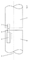
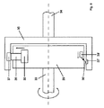
図1はそのロッキング突起が2で指示されているロッキングシリンダを示す。
前記のロッキング突起は軸線3の周りで回転可能となるようにシリンダ1内に装着されたチューブ4に回転可能にしっかりと接続されている。例えば作動ノブ6のような作動部材を支持しているピン5がチューブ4内に装着されている。作動部材6は間に配置された結合装置であって、前記チューブ4と、該チューブ4内に装着されたピン5とによって形成されている結合装置を介してロッキング突起2に接続されている。前記の結合装置は電気活性ポリマーを含有しないことが好ましい材料からつくられた従来の駆動要素7を含み、前記駆動要素はアクチュエータ8によって両方向矢印9の方向に係合位置と解放位置との間で運動可能である。図1に示す位置において、駆動要素7は、ノブ6の回転が空転状態に留まり、詳しくはロッキング突起2を何ら作動させないようにする仕方でピン5がチューブ4内で回転自在とさせうる解放位置にある。電気活性ポリマーからなるアクチュエータ8に電圧あるいは電流を加えた後、アクチュエータの寸法変化によって駆動要素7を移動させ、駆動要素7を(図示していない)チューブ4のくぼみに係合させ、このようにして作動ノブ6をロッキング突起2に結合させる。
FIG. 1 shows a locking cylinder whose locking projection is indicated by 2.
The locking protrusion is firmly connected to a
図1においてそれぞれ参照番号7および8で指示されている駆動要素およびアクチュエータの取り合わせの他に、代替的な取り合わせが示されている。第一の代替的な形態においては、アクチュエータ8′は垂直方向に配置され、矢印9′の方向での寸法変化によりレバーとして設計されている駆動要素7′を軸線10′の周りで枢動させることによってそのような枢動のためアクチュエータ8′から離れる方向に向いた駆動要素7′の端部をチューブ4の方向に枢動させて該駆動要素7′をチューブ4と係合させる。
In addition to the drive element and actuator combinations indicated in FIG. 1 by
別の代替的な形態においては、矢印9″の方向に寸法変化すると、レバーとして設計されている駆動要素7″に対して作用し、該駆動要素の方は軸線10″の周りを枢動して係合位置に到達するようなアクチュエータ8″が設けられている。
In another alternative, a change in size in the direction of the
図1に示すアクチュエータは電圧を加えると長手方向に伸長するか、あるいは横方向に短縮される電気活性ポリマーからつくられている。しかしながら、基本的には、膜として設計され、電圧を加えると所定方向に弓形となるアクチュエータを使用することも可能である。アクチュエータはまた、電圧を加えると曲がり、こうして例えば金属製ピンを運動させる電気活性ポリマーから構成してもよい。電気活性ポリマーは、活性電圧が切られると変化した寸法を保持するものとか、あるいは活性電圧が切られると元の寸法を復元するようなポリマーを含みうる。図1に示す形態によれば、活性電圧が切られると元の寸法を復元する電気活性ポリマーを使用することによって、アクチュエータが活性化された状態においてロッキング部材の作動が初めて可能とされるように保証する。活性電圧が切られた後、駆動要素が元の解放位置へ運動するようにアクチュエータがその元の寸法を復元させ、一方作動ノブ6並びにピン5が何ら作用することなく自在に空転するだけなのでロッキング部材の作動が阻止される。 The actuator shown in FIG. 1 is made of an electroactive polymer that stretches in the longitudinal direction or shortens in the lateral direction when a voltage is applied. However, basically, it is also possible to use an actuator which is designed as a membrane and becomes arcuate in a predetermined direction when a voltage is applied. The actuator may also be composed of an electroactive polymer that bends when a voltage is applied and thus moves, for example, a metal pin. Electroactive polymers can include polymers that retain their altered dimensions when the active voltage is turned off, or restore the original dimensions when the active voltage is turned off. According to the embodiment shown in FIG. 1, the use of an electroactive polymer that restores the original dimensions when the activation voltage is turned off allows the locking member to be activated for the first time in the activated state of the actuator. Guarantee. After the activation voltage has been switched off, the actuator restores its original dimensions so that the drive element moves to its original release position, while the actuating knob 6 and the pin 5 only freely rotate without any action. The operation of the member is prevented.
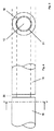
対照的に、図2に示す修正された形態における作動ノブ6はロッキング部材の非解放状態に封じられている。この状態において、ピン5はロッキング突起2を含むリングに回転可能にしっかりと永続的に接続されており、ロッキングシリンダ内で移動可能に案内される駆動要素7がピン5のくぼみと係合しているという点で図2に示す位置における作動ノブ6の回転は封じられている。アクチュエータ8に電圧を加えることによって初めて駆動要素7が解放され、ピンを再度運動自在となるようにしうるようアクチュエータ8が矢印11の方向に短縮される。傾動可能な駆動要素7′および7″を含む代替的な形態も同様に図2において代案として示されている。作動要素として、作動ノブ6はまた、片側あるいは両側においてキー機能を有するロッキングシリンダに代替させてもよい。
In contrast, the actuating knob 6 in the modified configuration shown in FIG. 2 is sealed in the unlocked state of the locking member. In this state, the pin 5 is rotatably and permanently connected to the ring containing the locking projection 2 so that the
図3に示す形態において、結合装置は整合して配置された2個のピン12および13によって構成されており、ピン12は例えば作動部材に接続あるいは結合され、ピン13は、例えばロッキング装置、例えばロッキング突起に接続あるいは結合されている。前記ピン12および13の回転軸線は14で指示されており、駆動要素15が前記回転軸線14に対して平行に横移動可能に案内されていて、該駆動要素15は電気活性ポリマーからつくられたアクチュエータ16によって係合位置と解放位置との間で運動可能である。係合位置において、前記駆動要素15はピン12と13との間での確実な接続と、前記2本のピンの間の回転可能なしっかりした接続との双方を提供するためにピン13の適当なくぼみ17において休止するように進む。駆動要素による結合を提供する代わりに、前記ピン12および13の相互に面する二つの端面に、あるいは二つの面の一方だけに粗面ポリマーあるいはイオン電気活性ポリマーを取り付けることが可能で、活性電圧を加えると二つの面が協働して摩擦係合を提供しピン12をピン13に結合させることができる。
In the form shown in FIG. 3, the coupling device is constituted by two
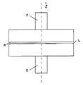
図4が側面図であり、図5が断面図である、図4および図5に示す形態において、ここでも2個のピン18および19が設けられており、ピン18は例えばノブのような作動部材に接続され、ピン19は例えばロッキング突起のようなロッキング装置に接続されている。この場合、ピン19は小径断面部分20を含み、該断面部分はピン18の軸線方向のくぼみに進入する。図3に示す形態とは対照的に、粗面ポリマーあるいはイオン電気活性ポリマーの取り付けは端面では行われず、ピン18および19の相互に面する外周面と内周面において行われる。非作動状態においては、ピン18の内周とピン19の小径部分20の外周との間で空隙21が保たれる。活性電圧を加えると、粗面ポリマーあるいはイオン電気活性ポリマーがピン18の内面とピン19の外面との間で摩擦係合を起こすように変化し、したがってピン18に接続された作動要素をピン19に接続されたロッキング部材と結合させる。
In the form shown in FIGS. 4 and 5 where FIG. 4 is a side view and FIG. 5 is a cross-sectional view, again two
図6に示されている結合装置の修正形態はアーマチュア(armature)、ロックローゼット(lock rosette)および埋込み錠(mortise lock)に組み込むのに特に適している。図6の左側に示されている部分22は例えばアーマチュアのラッチのような作動要素によって接続され、図面の右側に示されている部分23は例えばロックストライカープレート(lock striker−plate)アクチュエータに接続される。電気活性ポリマーからつくられ、例えば鋼ピン25のような駆動要素を解放位置と係合位置の間で運動させることができるアクチュエータ24がまた作動要素をロッキング装置に結合させるために鋼ピン25をくぼみ26中へ進入させることができるように設けられている。
The modified version of the coupling device shown in FIG. 6 is particularly suitable for incorporation in armatures, lock rosettes and mortise locks. The
図7に示す形態においては、図6に示す形態と対比すれば、適当に作動されると部分22および23の間で摩擦係合が形成されるように相互に面する面27および28に粗面ポリマーあるいはイオン電気活性ポリマーが設けられている。必要であれば、前記の相互に面する面27および28は力の伝達を確実に改善するために特殊な面構造を有するようにしてもよい。
In the configuration shown in FIG. 7, in contrast to the configuration shown in FIG. 6, the
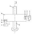
図8は図6および図7に示す形態の修正を示しており、この場合のロッキング装置の作動は、駆動要素30がアクチュエータ31によってくぼみ32中へ移動させられた後要素29の回転運動が封じられることによって阻止される。軸線方向に移動可能な駆動要素30の代わりに、半径方向に調整可能な駆動要素30′を設けることが可能であって、該駆動要素は前記要素29の回転を封じるためにアクチュエータ31′によって半径方向のくぼみ32′中へ移動することができる。この場合の前記要素29は一方では作動要素に繋がるピン33に接続され、他方では、例えばロックストライカープレート(lock striker−plate)アクチュエータに繋がるピン34に接続されている。
FIG. 8 shows a modification of the configuration shown in FIGS. 6 and 7, in which the operation of the locking device is such that the rotational movement of the
図9に類似の形態が示されており、同一の部分に対しては同じ参照番号が再度使用されている。図8に示す形態とは対照的に、基本的にピン33および34が相互に対して回転しうるようにするためにピン34と34の間で前記要素29の側で該要素29を囲むフォーク状あるいは円筒形の要素35が設けられている。駆動要素36がアクチュエータ38によってくぼみ37中へ移動することによって結合が再度行われる。確実係合の代案として、ポリマーが活性化すると摩擦係合を発生させることができるように前記要素29または35の相互に面する面に織地のポリマーあるいはイオン電気活性ポリマーを配置させることができる。アクチュエータ38′によって軸線の周りでくぼみ37′中へ枢動する駆動要素が36′によって指示されている。
A similar configuration is shown in FIG. 9, where the same reference numerals are used again for the same parts. In contrast to the configuration shown in FIG. 8, a fork that essentially surrounds the
要約すれば、ロッキング技術製品において電気活性ポリマーの使用が可能であり、かつ想起しうる複数の取り合わせが考えられ、どのような場合であっても錠が安定して解除され、かつ(または)安定してロックできることは明らかである。 In summary, the use of electroactive polymers in locking technology products is possible and multiple possible combinations are possible, in which case the lock is stably released and / or stable. Obviously it can be locked.
Claims (9)
Applications Claiming Priority (2)
| Application Number | Priority Date | Filing Date | Title |
|---|---|---|---|
| AT9512007A AT504333B8 (en) | 2007-06-19 | 2007-06-19 | DEVICE FOR LOCKING A LOCK |
| PCT/AT2008/000195 WO2008154664A1 (en) | 2007-06-19 | 2008-06-05 | Device for locking a lock |
Publications (1)
| Publication Number | Publication Date |
|---|---|
| JP2010530486A true JP2010530486A (en) | 2010-09-09 |
Family
ID=39367346
Family Applications (1)
| Application Number | Title | Priority Date | Filing Date |
|---|---|---|---|
| JP2010512460A Pending JP2010530486A (en) | 2007-06-19 | 2008-06-05 | Device to lock the lock |
Country Status (7)
| Country | Link |
|---|---|
| US (1) | US20100126240A1 (en) |
| EP (1) | EP2155990A1 (en) |
| JP (1) | JP2010530486A (en) |
| AT (1) | AT504333B8 (en) |
| IL (1) | IL202326A0 (en) |
| RU (1) | RU2010101332A (en) |
| WO (1) | WO2008154664A1 (en) |
Cited By (1)
| Publication number | Priority date | Publication date | Assignee | Title |
|---|---|---|---|---|
| JP2015071914A (en) * | 2013-10-04 | 2015-04-16 | シャーロック株式会社 | Handle lock device |
Families Citing this family (10)
| Publication number | Priority date | Publication date | Assignee | Title |
|---|---|---|---|---|
| CN101918661B (en) * | 2007-10-13 | 2013-09-04 | 索斯科公司 | Latch actuator and latch using same |
| DE202010002874U1 (en) * | 2010-02-26 | 2011-07-28 | Kiekert Ag | Lock for covers |
| DE102012013307A1 (en) * | 2012-06-26 | 2014-01-02 | Assa Abloy Sicherheitstechnik Gmbh | closing device |
| CA2877371A1 (en) | 2012-06-27 | 2014-01-03 | Treefrog Developments, Inc. | Tracking and control of personal effects |
| CA2903811A1 (en) | 2013-03-15 | 2014-09-25 | Spectrum Brands, Inc. | Electro-mechanical locks with bezel turning function |
| US9483891B1 (en) * | 2015-11-20 | 2016-11-01 | International Business Machines Corporation | Wireless lock |
| US11098463B2 (en) * | 2019-11-11 | 2021-08-24 | Caterpillar Inc. | Electrically activated polymer based locking system for earth moving equipment and method |
| DE102021202435A1 (en) | 2021-03-12 | 2022-09-15 | Zf Friedrichshafen Ag | Arrangement with a selector lever of an automatic transmission of a vehicle |
| CN114354158B (en) * | 2021-12-21 | 2023-08-01 | 中船重工鹏力(南京)智能装备系统有限公司 | Door lock inertia function dynamic detection equipment and detection method |
| CN115653414B (en) * | 2022-09-22 | 2024-04-12 | 东风柳州汽车有限公司 | Unlocking device for automobile hood lock |
Family Cites Families (9)
| Publication number | Priority date | Publication date | Assignee | Title |
|---|---|---|---|---|
| DE10343109A1 (en) * | 2003-09-18 | 2005-04-21 | Winkhaus Fa August | lock cylinder |
| US7299630B2 (en) * | 2004-03-12 | 2007-11-27 | Gm Global Technology Operations, Inc. | Positioning and locking mechanisms and articles that employ the same |
| EP1723614B1 (en) * | 2004-03-12 | 2012-01-04 | DOM-Sicherheitstechnik GmbH & Co. KG | Lock cylinder and locking method |
| US20050205364A1 (en) * | 2004-03-12 | 2005-09-22 | Browne Alan L | Variable resistance strut assemblies and articles containing the same |
| GB2412413A (en) * | 2004-03-26 | 2005-09-28 | Pbt | Piezo ceramic actuated clutch in a cylinder lock |
| US7331616B2 (en) * | 2004-07-15 | 2008-02-19 | General Motors Corporation | Hood latch assemblies utilizing active materials and methods of use |
| US7063377B2 (en) * | 2004-08-06 | 2006-06-20 | General Motors Corporation | Hood lift mechanisms utilizing active materials and methods of use |
| DE102004057747A1 (en) * | 2004-11-30 | 2006-06-01 | Normbau Beschläge und Ausstattungs GmbH | Coupling device for a locking technique |
| AT502365B1 (en) * | 2005-08-23 | 2009-05-15 | Evva Werke | RELEASE AND LOCKING ELEMENT |
-
2007
- 2007-06-19 AT AT9512007A patent/AT504333B8/en not_active IP Right Cessation
-
2008
- 2008-06-05 US US12/451,945 patent/US20100126240A1/en not_active Abandoned
- 2008-06-05 WO PCT/AT2008/000195 patent/WO2008154664A1/en active Application Filing
- 2008-06-05 RU RU2010101332/12A patent/RU2010101332A/en not_active Application Discontinuation
- 2008-06-05 EP EP08747911A patent/EP2155990A1/en not_active Withdrawn
- 2008-06-05 JP JP2010512460A patent/JP2010530486A/en active Pending
-
2009
- 2009-11-25 IL IL202326A patent/IL202326A0/en unknown
Cited By (1)
| Publication number | Priority date | Publication date | Assignee | Title |
|---|---|---|---|---|
| JP2015071914A (en) * | 2013-10-04 | 2015-04-16 | シャーロック株式会社 | Handle lock device |
Also Published As
| Publication number | Publication date |
|---|---|
| US20100126240A1 (en) | 2010-05-27 |
| AT504333B1 (en) | 2008-05-15 |
| RU2010101332A (en) | 2011-07-27 |
| EP2155990A1 (en) | 2010-02-24 |
| AT504333A4 (en) | 2008-05-15 |
| AT504333B8 (en) | 2008-09-15 |
| WO2008154664A1 (en) | 2008-12-24 |
| IL202326A0 (en) | 2010-06-30 |
Similar Documents
| Publication | Publication Date | Title |
|---|---|---|
| JP2010530486A (en) | Device to lock the lock | |
| JP4590411B2 (en) | Door lock with controllable handle operation | |
| JP5144500B2 (en) | Electromechanical locking device | |
| JP5148479B2 (en) | Electromechanical locking device | |
| US20100212381A1 (en) | Electro-mechanical lock assembly | |
| CN101903607A (en) | Handle device | |
| JP5144501B2 (en) | Electromechanical locking device | |
| JP5269884B2 (en) | Door lock | |
| US9683389B2 (en) | Movement lock for a locking element or an actuator in a locking system | |
| KR20080092230A (en) | Door lock | |
| KR101806612B1 (en) | vehicle door latch for preventing locking | |
| JP2005251726A (en) | Safety position switch | |
| JP2012180739A (en) | Closing device | |
| JP2020509268A (en) | Collet latch | |
| US6575505B1 (en) | Latch apparatus and method | |
| JP5921455B2 (en) | Latch device | |
| KR20100107270A (en) | Door latch device for automobile | |
| JP2574727B2 (en) | Latch mechanism for electric lock | |
| CN113811661B (en) | Vehicle door opening assembly | |
| FI111748B (en) | Electronic lock | |
| JPH1116437A (en) | Locking device of operating equipment for switch | |
| JP5260046B2 (en) | Locking device | |
| SE2250735A1 (en) | Blocker, arrangement and lock device | |
| JP4823871B2 (en) | Electric lock | |
| JP2010043411A (en) | Signal generating mechanism of emergency unlocking device |