JP2010528933A - Window wiper equipment - Google Patents
Window wiper equipment Download PDFInfo
- Publication number
- JP2010528933A JP2010528933A JP2010511552A JP2010511552A JP2010528933A JP 2010528933 A JP2010528933 A JP 2010528933A JP 2010511552 A JP2010511552 A JP 2010511552A JP 2010511552 A JP2010511552 A JP 2010511552A JP 2010528933 A JP2010528933 A JP 2010528933A
- Authority
- JP
- Japan
- Prior art keywords
- driven shaft
- crank
- window wiper
- wiper device
- screw
- Prior art date
- Legal status (The legal status is an assumption and is not a legal conclusion. Google has not performed a legal analysis and makes no representation as to the accuracy of the status listed.)
- Pending
Links
Images


Classifications
-
- B—PERFORMING OPERATIONS; TRANSPORTING
- B60—VEHICLES IN GENERAL
- B60S—SERVICING, CLEANING, REPAIRING, SUPPORTING, LIFTING, OR MANOEUVRING OF VEHICLES, NOT OTHERWISE PROVIDED FOR
- B60S1/00—Cleaning of vehicles
- B60S1/02—Cleaning windscreens, windows or optical devices
- B60S1/04—Wipers or the like, e.g. scrapers
- B60S1/06—Wipers or the like, e.g. scrapers characterised by the drive
- B60S1/16—Means for transmitting drive
- B60S1/18—Means for transmitting drive mechanically
- B60S1/24—Means for transmitting drive mechanically by rotary cranks
-
- B—PERFORMING OPERATIONS; TRANSPORTING
- B60—VEHICLES IN GENERAL
- B60S—SERVICING, CLEANING, REPAIRING, SUPPORTING, LIFTING, OR MANOEUVRING OF VEHICLES, NOT OTHERWISE PROVIDED FOR
- B60S1/00—Cleaning of vehicles
- B60S1/02—Cleaning windscreens, windows or optical devices
- B60S1/04—Wipers or the like, e.g. scrapers
- B60S1/32—Wipers or the like, e.g. scrapers characterised by constructional features of wiper blade arms or blades
- B60S1/34—Wiper arms; Mountings therefor
-
- B—PERFORMING OPERATIONS; TRANSPORTING
- B60—VEHICLES IN GENERAL
- B60S—SERVICING, CLEANING, REPAIRING, SUPPORTING, LIFTING, OR MANOEUVRING OF VEHICLES, NOT OTHERWISE PROVIDED FOR
- B60S1/00—Cleaning of vehicles
- B60S1/02—Cleaning windscreens, windows or optical devices
- B60S1/04—Wipers or the like, e.g. scrapers
- B60S1/06—Wipers or the like, e.g. scrapers characterised by the drive
- B60S1/16—Means for transmitting drive
- B60S1/166—Means for transmitting drive characterised by the combination of a motor-reduction unit and a mechanism for converting rotary into oscillatory movement
-
- B—PERFORMING OPERATIONS; TRANSPORTING
- B60—VEHICLES IN GENERAL
- B60S—SERVICING, CLEANING, REPAIRING, SUPPORTING, LIFTING, OR MANOEUVRING OF VEHICLES, NOT OTHERWISE PROVIDED FOR
- B60S1/00—Cleaning of vehicles
- B60S1/02—Cleaning windscreens, windows or optical devices
- B60S1/04—Wipers or the like, e.g. scrapers
- B60S1/32—Wipers or the like, e.g. scrapers characterised by constructional features of wiper blade arms or blades
Abstract
本発明は、特に自動車のためのウィンドウワイパ装置(10)であって、少なくとも1つの被駆動軸(102)を有しており、該被駆動軸にはクランク(101)が配置されている形式のものに関する。先行技術により公知のウィンドウワイパ装置では、被駆動軸が雄ねじ山を有しており、該雄ねじ山に、被駆動軸との相対回動不能な固定のためにナットをねじ込むことができる。しかしながらこのような形式の固定は、できるだけ小さな組み込みスペースを求める要求の高まりにもはや対応できるものではない。従って本発明によるウィンドウワイパ装置(10)では、被駆動軸(102)が、専ら及び/又は主として形状接続によりクランク(101,31,41)に固定可能である。 The invention relates to a window wiper device (10), in particular for a motor vehicle, having at least one driven shaft (102) on which a crank (101) is arranged. Related to things. In a window wiper device known from the prior art, the driven shaft has an external thread, and a nut can be screwed into the external thread for non-rotatable fixation with the driven shaft. However, this type of fixation is no longer able to meet the increasing demand for the smallest possible installation space. Therefore, in the window wiper device (10) according to the present invention, the driven shaft (102) can be fixed to the crank (101, 31, 41) exclusively and / or mainly by shape connection.
Description
本発明は、特に自動車のためのウィンドウワイパ装置であって、少なくとも1つの被駆動軸を有しており、該被駆動軸にはクランクが配置されている形式のものに関する。 The present invention relates to a window wiper device, in particular for a motor vehicle, having at least one driven shaft, on which the crank is arranged.
先行技術により公知のウィンドウワイパ装置では、被駆動軸が雄ねじ山を有しており、該雄ねじ山には、クランクを被駆動軸に対して相対回動不能に固定するためにナットがねじ込み可能である。このような形式の固定のためには、被駆動軸が少なくともほぼナットの厚さの寸法分だけクランクを越えて突出しなければならない。しかしながらこのような状況により、ウィンドウワイパ装置の領域における組み込みスペースに課する要求をますます高いものとするという問題が生じる。 In the window wiper device known from the prior art, the driven shaft has a male thread, and a nut can be screwed into the male thread to fix the crank relative to the driven shaft in a non-rotatable manner. is there. For this type of fixation, the driven shaft must protrude beyond the crank by at least the dimension of the nut thickness. However, this situation raises the problem of increasing the demands placed on the installation space in the area of the window wiper device.
発明の開示
そこで本発明の課題は、冒頭で述べた形式のウィンドウワイパ装置を改良して、これまでよりも僅かな組み込みスペースで済むようなウィンドウワイパ装置を提供することである。
DISCLOSURE OF THE INVENTION An object of the present invention is to improve a window wiper device of the type described at the beginning, and to provide a window wiper device that requires less installation space than before.
この課題を解決するために本発明の構成では、被駆動軸が、専ら及び/又は主として形状接続によりクランクに固定可能であるようにした。これにより将来的には、クランク上にねじ込まれる、従って突出するナットによるねじ固定は不要となる。結果としてウィンドウワイパ装置は、これまで必要だったナットの寸法分だけ、より扁平に構成することができる。本発明によるウィンドウワイパ装置により、基本的に、クランクを被駆動軸に固定するためのねじ結合を完全に省くこともできるので、これにより組み付けの手間も減じられる。 In order to solve this problem, in the configuration of the present invention, the driven shaft can be fixed to the crank exclusively and / or mainly by shape connection. In the future, this will eliminate the need for screwing with nuts that are screwed onto the crank and thus project. As a result, the window wiper device can be configured to be flatter by the dimension of the nut that has been required. With the window wiper device according to the invention, the screw connection for fixing the crank to the driven shaft can also be completely eliminated, which reduces the assembly effort.
被駆動軸が円筒状の外側ローレットを有しているならば、少なくとも1つの被駆動軸とクランクとの間の形状接続的な固定が特に簡単かつ安価に実現可能である。円錐状の外側ローレットとは異なり、円筒状の外側ローレットにより、被駆動軸に対して軸方向でクランクの座部に作用する力を吸収することができ、これによりクランクが意図に反して外れる恐れがなくなる。結果として円筒状の外側ローレットを有したクランクは、ねじがなくても確実に被駆動軸上に相対回動不能に位置固定することができる。 If the driven shaft has a cylindrical outer knurl, it is particularly easy and inexpensive to realize a shape-connective fixing between at least one driven shaft and the crank. Unlike the conical outer knurl, the cylindrical outer knurl can absorb the force acting on the crank seat in the axial direction with respect to the driven shaft, which can cause the crank to come off unintentionally. Disappears. As a result, the crank having the cylindrical outer knurl can be securely fixed on the driven shaft so as not to rotate relative to the driven shaft without a screw.
少なくとも1つの被駆動軸とクランクとの間の固定過程を容易にするために、特に自動的な固定のために、被駆動軸は内側孔を有することができる。 In order to facilitate the fixing process between the at least one driven shaft and the crank, the driven shaft can have an inner bore, in particular for automatic locking.
内側孔には雌ねじ山を設けることができる。これにより、クランクが被駆動軸上に押し嵌められる、少なくとも1つの被駆動軸とクランクとの間の固定過程を容易にするために、ねじを組み付け補助手段として使用することができる。組み付け補助手段としてねじを使用することにより、外部圧力を、ウィンドウワイパ装置全体に加える必要がない。従って、クランクの下側に配置されている例えばセンサのような圧力に敏感な構成部分を損傷から保護することができる。 The inner hole can be provided with an internal thread. Thereby, the screw can be used as an assembling auxiliary means in order to facilitate the fixing process between at least one driven shaft and the crank, in which the crank is pressed onto the driven shaft. By using a screw as an assembly auxiliary means, it is not necessary to apply external pressure to the entire window wiper device. Thus, pressure sensitive components such as sensors located under the crank can be protected from damage.
ウィンドウワイパ装置のための組み込みスペースをできるだけ小さくすることができるように、円筒状の外側ローレットが少なくとも1つの被駆動軸の上端部に設けられていると有利である。 Advantageously, a cylindrical outer knurl is provided at the upper end of at least one driven shaft so that the installation space for the window wiper device can be as small as possible.
本発明の別の有利な構成では、クランクはねじ工具によって少なくとも1つの被駆動軸に組み付けられる。これにより固定過程は自動化され、この場合同時に、クランクの下側に配置された圧力に敏感な構成部分が保護される。 In a further advantageous configuration of the invention, the crank is assembled to at least one driven shaft by means of a screw tool. This automates the fixing process, and at the same time protects the pressure-sensitive components located below the crank.
自動化された固定過程のために、ねじ工具が内側孔内にねじ込まれる。この際、雌ねじ山が内側孔に切られる、又は、既に設けられている雌ねじ山を、被駆動軸の熱的又は機械的処理後に場合によっては生じる形状的変化を相殺するために、後加工する。ねじ込まれたねじ工具は、組み付け中、被駆動軸を軸方向でロックする。 A screw tool is screwed into the inner bore for an automated fixing process. At this time, the female thread is cut into the inner hole, or the already provided female thread is post-processed in order to cancel out any shape changes that may occur after thermal or mechanical processing of the driven shaft. . The screwed screw tool locks the driven shaft in the axial direction during assembly.
ねじ工具に押さえプランジャを設けることができる。押さえプランジャはねじ工具が完全にねじ込まれた後、クランクを少なくとも1つの被駆動軸へと押し付ける。従ってクランクは、ねじ工具が外される際に少なくとも1つの被駆動軸から解離されない、又は回されない。 A holding plunger can be provided on the screw tool. The holding plunger presses the crank against the at least one driven shaft after the screw tool is fully screwed. The crank is therefore not disengaged or turned from the at least one driven shaft when the screw tool is removed.
自動化された固定過程のためには、ねじ工具が液圧的又はニューマチック式に操作可能であるならば有利である。 For an automated fastening process, it is advantageous if the screw tool can be operated hydraulically or pneumatically.
少なくとも1つの被駆動軸へのクランクの固定を最良にするためには、クランクを短いねじによって軸方向で固定することができる。このねじは、ねじ工具の個所で使用するねじよりもずっと短くて良い。このねじは高強度の材料から製造する必要もない。ねじは、誤って外れることのないように接着剤によって固定することができる。 In order to best fix the crank to the at least one driven shaft, the crank can be fixed axially with a short screw. This screw may be much shorter than the screw used at the screw tool. The screw does not have to be manufactured from a high strength material. The screw can be fixed with an adhesive so that it cannot be accidentally removed.
発明の実施の形態
次に、本発明による実施例を図面につき詳しく説明する。
Embodiments of the invention will now be described in detail with reference to the drawings.
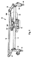
図1には、シートバーから成る管11を備えたウィンドウワイパ装置10が示されている。管11にはワイパモータ12とワイパ軸受13,14とが配置されている。ワイパ軸受13,14内にはワイパ軸15,16が軸受されていて、ワイパ軸15,16にはここには詳しくは示されていないワイパアームを組み付けることができる。ワイパ軸15,16はスイングアーム17,18に相対回動不能に結合されている。スイングアーム17,18はカップラ19に結合されている。押しロッド100はスイングアーム18をクランク101に接続している。クランク101は、被駆動軸102に相対回動不能に結合されている。被駆動軸102はワイパ伝動装置13からワイパモータ12の出力を受ける。
FIG. 1 shows a
図2には被駆動軸20が示されている。この被駆動軸20にはナット21によって固定されたクランク22が公知技術の形式で組み付けられている。クランク22をナット21によって固定することができるように、被駆動軸20は、所定の寸法だけクランク22を越えて突出していなければならない。この寸法は少なくともナット21の厚さに相当するものである。この寸法のために、所定の組み込みスペースが存在しなければならない。
FIG. 2 shows a driven
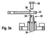
図3aには、被駆動軸30とクランク31とねじ32とが示されている。被駆動軸30は、雌ねじ山を備えた内側孔33を有している。さらに、被駆動軸30の上方領域には外側ローレット35が設けられている。クランク31には貫通孔34が設けられている。ねじ32は、クランク31を被駆動軸30に押し付けるための組み付け補助手段として働く。
FIG. 3 a shows a driven
固定過程の最初に、クランク31が被駆動軸30上に置かれ、ねじ32が貫通孔34に差し込まれる(図3b参照)。
At the beginning of the fixing process, the
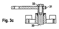
固定過程中に、ねじ32が、被駆動軸30の内側孔33に設けられた雌ねじ山内にねじ込まれる。この場合、クランク31は被駆動軸30上に、被駆動軸30に設けられた外側ローレット35を介して押し付けられる。クランク31が被駆動軸30上に押し嵌められた後、被駆動軸30とクランク31との間には形状接続的な結合が生じている。ねじ32は次の組み付けステップで、内側孔33の雌ねじ山から再びねじ外すことができる。又は、ねじ32は、クランク31が、被駆動軸30において軸方向でその位置を保持することを保証するために、付加的な固定手段として被駆動軸30内に残ることができる。
During the fixing process, the
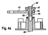
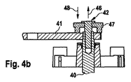
図4aには、被駆動軸40と、クランク41と、押さえプランジャ47を備えたねじ工具42とが示されている。被駆動軸40は、外側ローレット43と内側孔45とを有していて、内側孔45には雌ねじ山を設けることができる。クランク41には貫通孔44が設けられており、この貫通孔44にはねじ工具42を差し込むことができる。
FIG. 4 a shows a driven
固定過程の最初に、クランク41が被駆動軸40上に置かれ、ねじ工具42は内側孔45内に導入される(図4a参照)。
At the beginning of the fixing process, the
次の組み付けステップでは、ねじ工具42が、内側孔45に雌ねじ山を切る、又は、設けられていた雌ねじ山に後加工を施す。ねじ込まれたねじ工具42は被駆動軸40を軸方向でロックする。押さえプランジャ47は、回動を防止するためにクランク41を固定する。同時に、押さえプランジャ47はクランク41を外側ローレット43を介して被駆動軸40上に押し嵌める(図4b参照)。
In the next assembly step, the
ねじ工具42を矢印46の方向で外すように回すと、押さえプランジャ47はクランク41を矢印48の方向でロックし、クランク41を回動しないように固定する(図4b参照)。
When the
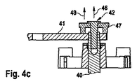
ねじ工具42が矢印46の方向で外されるように回転されると、押さえプランジャ47も矢印49の方向で上方に向かってクランク41から外すことができる(図4c参照)。
When the
最後に、クランク41の軸方向の固定のために、被駆動軸40内には短いねじ(図示せず)がねじ込まれる。このねじは、ねじ32よりも著しく短くて良く、高強度の材料から製造しなくても良い。さらにこのねじは接着剤によって、誤って外れることのないように固定されている。
Finally, in order to fix the
Claims (10)
被駆動軸(102,30,40)が、専ら及び/又は主として形状接続によりクランク(101,31,41)に固定可能であることを特徴とする、特に自動車のためのウィンドウワイパ装置。 In particular, a window wiper device (10) for a motor vehicle having at least one driven shaft (102, 30, 40) on which a crank (101, 31, 41) is arranged. In the form of
Window wiper device, in particular for a motor vehicle, characterized in that the driven shaft (102, 30, 40) can be fixed to the crank (101, 31, 41) exclusively and / or mainly by a shape connection.
Applications Claiming Priority (2)
| Application Number | Priority Date | Filing Date | Title |
|---|---|---|---|
| DE102007027662.3A DE102007027662B4 (en) | 2007-06-15 | 2007-06-15 | wiper device |
| PCT/EP2008/054521 WO2008151871A1 (en) | 2007-06-15 | 2008-04-15 | Windshield wiper device |
Publications (1)
| Publication Number | Publication Date |
|---|---|
| JP2010528933A true JP2010528933A (en) | 2010-08-26 |
Family
ID=39673412
Family Applications (1)
| Application Number | Title | Priority Date | Filing Date |
|---|---|---|---|
| JP2010511552A Pending JP2010528933A (en) | 2007-06-15 | 2008-04-15 | Window wiper equipment |
Country Status (7)
| Country | Link |
|---|---|
| EP (1) | EP2155523A1 (en) |
| JP (1) | JP2010528933A (en) |
| KR (1) | KR20100018565A (en) |
| CN (1) | CN101687491B (en) |
| BR (1) | BRPI0812003A2 (en) |
| DE (1) | DE102007027662B4 (en) |
| WO (1) | WO2008151871A1 (en) |
Families Citing this family (2)
| Publication number | Priority date | Publication date | Assignee | Title |
|---|---|---|---|---|
| DE102008041864A1 (en) * | 2008-08-13 | 2010-02-18 | Robert Bosch Gmbh | Output shaft for a windshield wiper drive |
| DE102009027285A1 (en) * | 2009-06-29 | 2010-12-30 | Robert Bosch Gmbh | Drive unit of a windshield wiper device in a vehicle |
Citations (2)
| Publication number | Priority date | Publication date | Assignee | Title |
|---|---|---|---|---|
| DE4339593A1 (en) * | 1993-11-20 | 1995-05-24 | Teves Gmbh Alfred | Screen wiper system for vehicle |
| JP2005520999A (en) * | 2002-03-22 | 2005-07-14 | ヴァレオ エキプマン エレクトリク モトゥール | Assembly including pulley for automobile alternator and method for assembling the same |
Family Cites Families (10)
| Publication number | Priority date | Publication date | Assignee | Title |
|---|---|---|---|---|
| DE3525215A1 (en) * | 1985-07-15 | 1987-01-22 | Saito Motors Co | TURNTABLE WIPER |
| FR2716658B1 (en) * | 1994-02-28 | 1996-04-19 | Valeo Systemes Dessuyage | Wiper device comprising improved means of coupling between the motor shaft and the drive head. |
| DE19642666A1 (en) * | 1996-03-26 | 1997-10-02 | Bosch Gmbh Robert | Bearing of drive shafts of a wiper system |
| DE19945091A1 (en) * | 1999-09-21 | 2001-04-19 | Bosch Gmbh Robert | Drive shaft for a wiper |
| DE10154640A1 (en) * | 2001-11-07 | 2003-05-15 | Bosch Gmbh Robert | Windscreen wiper device, in particular for a motor vehicle |
| DE10316181A1 (en) * | 2003-04-09 | 2004-12-02 | Robert Bosch Gmbh | Wiper unit especially for a motor vehicle has drive shaft with toothed end connected to oscillating crank |
| KR100537950B1 (en) * | 2003-12-06 | 2005-12-20 | 동양기전 주식회사 | Wiper assembly |
| DE10361454A1 (en) * | 2003-12-23 | 2005-07-28 | Robert Bosch Gmbh | Lever-shaft device, method for producing a lever-shaft device and windshield wiper system with a lever-shaft device |
| DE102004006340A1 (en) * | 2004-02-10 | 2005-08-25 | Robert Bosch Gmbh | Windscreen wiper has arm attached to mounting which fits over wiper shaft and breaks in accidents to reduce injury to pedestrians |
| FR2907080B1 (en) * | 2006-10-13 | 2009-06-26 | Peugeot Citroen Automobiles Sa | DEVICE FOR FIXING A WINDSCREEN WIPER ARM FOR A MOTOR VEHICLE |
-
2007
- 2007-06-15 DE DE102007027662.3A patent/DE102007027662B4/en not_active Expired - Fee Related
-
2008
- 2008-04-15 BR BRPI0812003-0A2A patent/BRPI0812003A2/en not_active IP Right Cessation
- 2008-04-15 JP JP2010511552A patent/JP2010528933A/en active Pending
- 2008-04-15 WO PCT/EP2008/054521 patent/WO2008151871A1/en active Application Filing
- 2008-04-15 EP EP08749559A patent/EP2155523A1/en not_active Withdrawn
- 2008-04-15 CN CN2008800200547A patent/CN101687491B/en not_active Expired - Fee Related
- 2008-04-15 KR KR1020097026134A patent/KR20100018565A/en not_active Application Discontinuation
Patent Citations (2)
| Publication number | Priority date | Publication date | Assignee | Title |
|---|---|---|---|---|
| DE4339593A1 (en) * | 1993-11-20 | 1995-05-24 | Teves Gmbh Alfred | Screen wiper system for vehicle |
| JP2005520999A (en) * | 2002-03-22 | 2005-07-14 | ヴァレオ エキプマン エレクトリク モトゥール | Assembly including pulley for automobile alternator and method for assembling the same |
Also Published As
| Publication number | Publication date |
|---|---|
| DE102007027662A1 (en) | 2008-12-18 |
| EP2155523A1 (en) | 2010-02-24 |
| BRPI0812003A2 (en) | 2014-11-18 |
| CN101687491B (en) | 2012-11-14 |
| DE102007027662B4 (en) | 2017-08-24 |
| KR20100018565A (en) | 2010-02-17 |
| CN101687491A (en) | 2010-03-31 |
| WO2008151871A1 (en) | 2008-12-18 |
Similar Documents
| Publication | Publication Date | Title |
|---|---|---|
| EP2835541B1 (en) | Anti-rattle sleeve for a hinge joint | |
| JP5886286B2 (en) | Apparatus having spherical element to be crimped, crimping method and crimping system | |
| US20070127982A1 (en) | Device for pivotably connecting at least two components and a method for mounting the device | |
| JP2010513866A (en) | Apparatus and method for tightening a nut disposed on a screw end, and assembled washer and nut for such apparatus | |
| JP2002089534A (en) | Screwed type tightener | |
| JP2009530169A (en) | Bolt joint | |
| US9016971B2 (en) | Motor vehicle elastic suspension joint and motor vehicle structure comprising such a joint | |
| CA2706819C (en) | Engagement unit for attaching and for engaging a threaded bolt | |
| JP2010528933A (en) | Window wiper equipment | |
| EP2735747B1 (en) | Nut rotation prevention structure | |
| US9126295B2 (en) | Device for the position-adjustment and attachment of a locking member on a support with compensation for play | |
| US20120121360A1 (en) | Fastening Device and Fastening System | |
| JP2006076560A (en) | Pressing device of rack to pinion | |
| CN101341051B (en) | Fastening device | |
| EP0508856A1 (en) | Safety clamping device of a male element in a caliper of a female element, used particularly to join two lengths of the steering column of an automotive vehicle | |
| US20100224086A1 (en) | Disposable sleeve | |
| JP2007315437A (en) | Fastening device | |
| JP2006132676A (en) | Connection structure of ball bearing | |
| JP2015152079A (en) | Bolt and bolt fastening method | |
| JP5172506B2 (en) | Annular elastic body mounting device | |
| US20150226268A1 (en) | Geared Motor | |
| JP2008309295A (en) | Flare joint | |
| US20080286040A1 (en) | Device for Connecting an Intermediate Shaft to a Pinion of a Steering Mechanism | |
| JP2003511292A (en) | Wiping device | |
| JP2009228833A (en) | Screw looseness preventive structure |
Legal Events
| Date | Code | Title | Description |
|---|---|---|---|
| RD04 | Notification of resignation of power of attorney |
Free format text: JAPANESE INTERMEDIATE CODE: A7424 Effective date: 20101228 |
|
| A131 | Notification of reasons for refusal |
Free format text: JAPANESE INTERMEDIATE CODE: A131 Effective date: 20111111 |
|
| A02 | Decision of refusal |
Free format text: JAPANESE INTERMEDIATE CODE: A02 Effective date: 20120419 |