JP2010528255A - Fuel combustion system, combustion method and burner - Google Patents
Fuel combustion system, combustion method and burner Download PDFInfo
- Publication number
- JP2010528255A JP2010528255A JP2010510439A JP2010510439A JP2010528255A JP 2010528255 A JP2010528255 A JP 2010528255A JP 2010510439 A JP2010510439 A JP 2010510439A JP 2010510439 A JP2010510439 A JP 2010510439A JP 2010528255 A JP2010528255 A JP 2010528255A
- Authority
- JP
- Japan
- Prior art keywords
- burner
- fuel
- air
- outlet
- porous material
- Prior art date
- Legal status (The legal status is an assumption and is not a legal conclusion. Google has not performed a legal analysis and makes no representation as to the accuracy of the status listed.)
- Granted
Links
- 239000000446 fuel Substances 0.000 title claims abstract description 261
- 238000002485 combustion reaction Methods 0.000 title claims abstract description 40
- 238000009841 combustion method Methods 0.000 title claims description 26
- 239000007788 liquid Substances 0.000 claims abstract description 51
- 238000004891 communication Methods 0.000 claims abstract description 40
- 239000012530 fluid Substances 0.000 claims abstract description 39
- 239000007789 gas Substances 0.000 claims description 57
- 239000011148 porous material Substances 0.000 claims description 57
- 238000001704 evaporation Methods 0.000 claims description 19
- 238000002156 mixing Methods 0.000 claims description 15
- 239000000203 mixture Substances 0.000 claims description 8
- QVGXLLKOCUKJST-UHFFFAOYSA-N atomic oxygen Chemical compound [O] QVGXLLKOCUKJST-UHFFFAOYSA-N 0.000 claims description 6
- 229910052760 oxygen Inorganic materials 0.000 claims description 6
- 239000001301 oxygen Substances 0.000 claims description 6
- 238000002347 injection Methods 0.000 claims description 4
- 239000007924 injection Substances 0.000 claims description 4
- 238000005259 measurement Methods 0.000 claims description 4
- 230000008859 change Effects 0.000 abstract description 3
- 230000008020 evaporation Effects 0.000 description 16
- 239000000571 coke Substances 0.000 description 9
- 238000000034 method Methods 0.000 description 9
- 239000006260 foam Substances 0.000 description 8
- ATUOYWHBWRKTHZ-UHFFFAOYSA-N Propane Chemical compound CCC ATUOYWHBWRKTHZ-UHFFFAOYSA-N 0.000 description 6
- 230000007246 mechanism Effects 0.000 description 6
- 239000003350 kerosene Substances 0.000 description 5
- 230000015572 biosynthetic process Effects 0.000 description 4
- 229910052751 metal Inorganic materials 0.000 description 4
- 239000002184 metal Substances 0.000 description 4
- 230000002411 adverse Effects 0.000 description 3
- 230000008901 benefit Effects 0.000 description 3
- 239000001294 propane Substances 0.000 description 3
- 238000012546 transfer Methods 0.000 description 3
- UHZZMRAGKVHANO-UHFFFAOYSA-M chlormequat chloride Chemical compound [Cl-].C[N+](C)(C)CCCl UHZZMRAGKVHANO-UHFFFAOYSA-M 0.000 description 2
- 230000001276 controlling effect Effects 0.000 description 2
- 239000002283 diesel fuel Substances 0.000 description 2
- 230000000694 effects Effects 0.000 description 2
- VNWKTOKETHGBQD-UHFFFAOYSA-N methane Chemical compound C VNWKTOKETHGBQD-UHFFFAOYSA-N 0.000 description 2
- 230000008569 process Effects 0.000 description 2
- 239000007921 spray Substances 0.000 description 2
- 239000000126 substance Substances 0.000 description 2
- UGFAIRIUMAVXCW-UHFFFAOYSA-N Carbon monoxide Chemical compound [O+]#[C-] UGFAIRIUMAVXCW-UHFFFAOYSA-N 0.000 description 1
- NINIDFKCEFEMDL-UHFFFAOYSA-N Sulfur Chemical compound [S] NINIDFKCEFEMDL-UHFFFAOYSA-N 0.000 description 1
- 239000000956 alloy Substances 0.000 description 1
- 229910045601 alloy Inorganic materials 0.000 description 1
- 238000004458 analytical method Methods 0.000 description 1
- 238000013459 approach Methods 0.000 description 1
- 230000036760 body temperature Effects 0.000 description 1
- 238000009529 body temperature measurement Methods 0.000 description 1
- 239000001273 butane Substances 0.000 description 1
- 229910002091 carbon monoxide Inorganic materials 0.000 description 1
- 230000003197 catalytic effect Effects 0.000 description 1
- UPHIPHFJVNKLMR-UHFFFAOYSA-N chromium iron Chemical compound [Cr].[Fe] UPHIPHFJVNKLMR-UHFFFAOYSA-N 0.000 description 1
- 238000004939 coking Methods 0.000 description 1
- 239000004020 conductor Substances 0.000 description 1
- 238000011109 contamination Methods 0.000 description 1
- 238000000354 decomposition reaction Methods 0.000 description 1
- 238000010586 diagram Methods 0.000 description 1
- 239000000835 fiber Substances 0.000 description 1
- 239000002657 fibrous material Substances 0.000 description 1
- 239000006261 foam material Substances 0.000 description 1
- 239000003502 gasoline Substances 0.000 description 1
- 238000010438 heat treatment Methods 0.000 description 1
- 239000000463 material Substances 0.000 description 1
- IJDNQMDRQITEOD-UHFFFAOYSA-N n-butane Chemical compound CCCC IJDNQMDRQITEOD-UHFFFAOYSA-N 0.000 description 1
- OFBQJSOFQDEBGM-UHFFFAOYSA-N n-pentane Natural products CCCCC OFBQJSOFQDEBGM-UHFFFAOYSA-N 0.000 description 1
- 239000003345 natural gas Substances 0.000 description 1
- 238000013021 overheating Methods 0.000 description 1
- 230000003647 oxidation Effects 0.000 description 1
- 238000007254 oxidation reaction Methods 0.000 description 1
- 230000005855 radiation Effects 0.000 description 1
- 230000003134 recirculating effect Effects 0.000 description 1
- 238000011084 recovery Methods 0.000 description 1
- 230000001105 regulatory effect Effects 0.000 description 1
- 230000004044 response Effects 0.000 description 1
- 238000005507 spraying Methods 0.000 description 1
- 230000006641 stabilisation Effects 0.000 description 1
- 238000011105 stabilization Methods 0.000 description 1
- 239000010935 stainless steel Substances 0.000 description 1
- 229910001220 stainless steel Inorganic materials 0.000 description 1
- 229910052717 sulfur Inorganic materials 0.000 description 1
- 239000011593 sulfur Substances 0.000 description 1
- 238000011144 upstream manufacturing Methods 0.000 description 1
- 230000008016 vaporization Effects 0.000 description 1
Images


Classifications
-
- F—MECHANICAL ENGINEERING; LIGHTING; HEATING; WEAPONS; BLASTING
- F02—COMBUSTION ENGINES; HOT-GAS OR COMBUSTION-PRODUCT ENGINE PLANTS
- F02C—GAS-TURBINE PLANTS; AIR INTAKES FOR JET-PROPULSION PLANTS; CONTROLLING FUEL SUPPLY IN AIR-BREATHING JET-PROPULSION PLANTS
- F02C1/00—Gas-turbine plants characterised by the use of hot gases or unheated pressurised gases, as the working fluid
-
- F—MECHANICAL ENGINEERING; LIGHTING; HEATING; WEAPONS; BLASTING
- F23—COMBUSTION APPARATUS; COMBUSTION PROCESSES
- F23D—BURNERS
- F23D17/00—Burners for combustion conjointly or alternatively of gaseous or liquid or pulverulent fuel
- F23D17/002—Burners for combustion conjointly or alternatively of gaseous or liquid or pulverulent fuel gaseous or liquid fuel
-
- F—MECHANICAL ENGINEERING; LIGHTING; HEATING; WEAPONS; BLASTING
- F23—COMBUSTION APPARATUS; COMBUSTION PROCESSES
- F23D—BURNERS
- F23D11/00—Burners using a direct spraying action of liquid droplets or vaporised liquid into the combustion space
- F23D11/36—Details, e.g. burner cooling means, noise reduction means
- F23D11/44—Preheating devices; Vaporising devices
- F23D11/441—Vaporising devices incorporated with burners
- F23D11/443—Vaporising devices incorporated with burners heated by the main burner flame
-
- F—MECHANICAL ENGINEERING; LIGHTING; HEATING; WEAPONS; BLASTING
- F23—COMBUSTION APPARATUS; COMBUSTION PROCESSES
- F23C—METHODS OR APPARATUS FOR COMBUSTION USING FLUID FUEL OR SOLID FUEL SUSPENDED IN A CARRIER GAS OR AIR
- F23C2700/00—Special arrangements for combustion apparatus using fluent fuel
- F23C2700/02—Combustion apparatus using liquid fuel
- F23C2700/026—Combustion apparatus using liquid fuel with pre-vaporising means
-
- F—MECHANICAL ENGINEERING; LIGHTING; HEATING; WEAPONS; BLASTING
- F23—COMBUSTION APPARATUS; COMBUSTION PROCESSES
- F23N—REGULATING OR CONTROLLING COMBUSTION
- F23N2237/00—Controlling
- F23N2237/08—Controlling two or more different types of fuel simultaneously
Landscapes
- Engineering & Computer Science (AREA)
- Chemical & Material Sciences (AREA)
- Combustion & Propulsion (AREA)
- Mechanical Engineering (AREA)
- General Engineering & Computer Science (AREA)
- Spray-Type Burners (AREA)
- Wick-Type Burners And Burners With Porous Materials (AREA)
- Regulation And Control Of Combustion (AREA)
- Gas Burners (AREA)
Abstract
この発明の燃料燃焼システム100は、液体燃料105を含む第1のソース、ガス燃料103を含む第2のソース、及び前記第1及び第2のソースに連結され、前記液体燃料と前記ガス燃料に選択的に流体連通されて前記燃料を収容する燃焼バーナー20を含む。前記バーナー20は、当該バーナー20又は前記システムに変更なく前記液体燃料の燃焼と前記ガス燃料の燃焼との間で切り替えることができる。
【選択図】図7The fuel combustion system 100 of the present invention is connected to a first source including a liquid fuel 105, a second source including a gas fuel 103, and the first and second sources, and the liquid fuel and the gas fuel are connected to each other. A combustion burner 20 is provided that is selectively in fluid communication and contains the fuel. The burner 20 can be switched between combustion of the liquid fuel and combustion of the gas fuel without change to the burner 20 or the system.
[Selection] Figure 7
Description
本発明は、燃料燃焼システム、その構成要素及び燃焼方法に関するものである。 The present invention relates to a fuel combustion system, components thereof, and a combustion method.
液体燃料バーナーは、二つのカテゴリー、すなわち噴霧バーナーと蒸発バーナーとに分類できる。噴霧バーナーで、高圧と高速エアの組み合わせを用いて、オリフィスを通じて液体燃料をフローイングし、燃料を小さな滴に分散する。燃料の小さな滴は、表面対体積の割合効果によってエアと混合し、一般的に燃料の大きな滴より更に容易に蒸発し、燃焼する。蒸発バーナーで、燃料は噴霧の援助なく加熱され、蒸発する。その後、蒸発した燃料はエアと混合し、燃焼される。一部の場合、電気ヒーターが用いられ、燃料の蒸発を助ける。その他の場合、燃焼工程からの熱は燃料を蒸発させるのに十分である。また、予熱されたエアは、芯から燃料の蒸発を助けることができる。 Liquid fuel burners can be divided into two categories: spray burners and evaporative burners. A spray burner uses a combination of high pressure and high velocity air to flow liquid fuel through an orifice and disperse the fuel into small drops. Small drops of fuel mix with air by the surface-to-volume ratio effect and generally evaporate and burn more easily than large drops of fuel. With an evaporative burner, the fuel is heated and evaporated without the aid of spraying. The evaporated fuel is then mixed with air and burned. In some cases, electric heaters are used to help fuel evaporation. In other cases, the heat from the combustion process is sufficient to evaporate the fuel. The preheated air can also help fuel evaporation from the wick.
ガス燃料バーナーは、燃料が気体状態で始まるため、燃料を蒸発させる必要がない。多くのガス燃料バーナーは、燃焼前に燃料とエアを予め混合したり、部分的に予め混合する。フレームは、熱い排気物の再循環を用いたり、鈍頭物体を用いたり、燃料-エア混合物を予熱した後、フレームを金属繊維や泡に安定化させるために、泡又は繊維材料を用いたり、又は排気物を再循環させ、供給速度において大きい変動のフレームを安定化させる旋回フローフィールドを用いることで安定化できる。 The gas fuel burner does not need to evaporate the fuel because the fuel starts in a gaseous state. Many gas fuel burners pre-mix or partially pre-mix fuel and air before combustion. The frame uses hot exhaust recirculation, blunt bodies, or after preheating the fuel-air mixture, using foam or fiber material to stabilize the frame to metal fibers or foam, Alternatively, it can be stabilized by recirculating the exhaust and using a swirl flow field that stabilizes the frame with large fluctuations in the feed rate.
本発明は、燃料燃焼システム、その構成要素及び燃焼方法に関するものである。
本発明は、液体燃料を蒸発させ、ガス燃料を完全に燃焼させることもできるバーナーで、非常に低い排出で液体燃料を燃焼する構成要素、システム及び方法を提供する。例えば、バーナーと、バーナーのコントローラが外部燃焼エンジン、化学プロセッサー又はヒーターに用いられる。一部の実施形態で、バーナーは液体又はガス燃料、点火率及びエア/燃料の割合を含む燃料形態の様々な範囲に関して燃焼を安定化させ得る旋回の安定したバーナーである。バーナー又は外部燃焼システムの燃料柔軟性は、燃料の選択が限定される際の緊急状況で非常に有用であり得る。
The present invention relates to a fuel combustion system, components thereof, and a combustion method.
The present invention provides components, systems and methods for burning liquid fuel with very low emissions, with a burner that can also evaporate liquid fuel and burn gas fuel completely. For example, burners and burner controllers are used for external combustion engines, chemical processors or heaters. In some embodiments, the burner is a swirling stable burner that can stabilize combustion for various ranges of fuel forms including liquid or gas fuel, ignition rate and air / fuel ratio. The fuel flexibility of the burner or external combustion system can be very useful in emergency situations when the choice of fuel is limited.
バーナーは、旋回安定を妨害せず、コークスの形成に対して限られた傾向で液体燃料を蒸気化させるためのメカニズムを含む。ガス燃料は、同一のバーナーで作動され、エアとの混合と燃焼前に蒸発させるメカニズムを通過できる。コントローラは、一つのシステムを如何なるハードウェアの変更もなく、気体又は液体燃料で作動させるようにし、即ち、単一のバーナーは液体燃料だけでなく、ガス燃料でも作動できる。 The burner includes a mechanism for vaporizing the liquid fuel with a limited tendency to coke formation without disturbing swirl stability. The gas fuel is operated with the same burner and can pass through a mechanism that mixes with air and evaporates prior to combustion. The controller allows one system to operate with gas or liquid fuel without any hardware changes, i.e. a single burner can operate with gas fuel as well as liquid fuel.
一実施形態で、本発明は、液体燃料を含む第1のソース、ガス燃料を含む第2のソース、及び第1及び第2のソースに接続され、液体燃料とガス燃料に選択的に流体連通され、燃料を収容する燃焼バーナーを含むシステムであって、バーナーは、バーナー又はシステムの変更なく、液体燃料の燃焼とガス燃料の燃焼との間で切り替えることができることを特徴とする。 In one embodiment, the present invention is connected to a first source including liquid fuel, a second source including gas fuel, and first and second sources, and selectively in fluid communication with the liquid fuel and the gas fuel. And a system comprising a combustion burner containing fuel, characterized in that the burner can be switched between combustion of liquid fuel and combustion of gas fuel without change of the burner or system.
実施形態は、以下の特徴のうち一つ以上を含むことができる。システムは、第1のソース又は第2のソースからバーナーへ燃料のフローをコントロールするように構成されたコントローラを更に含む。システムは、バーナーの出力測定に基づいて第1のソース又は第2のソースからバーナーへ燃料のフローをコントロールするように構成されたコントローラを更に含む。システムは、燃料/ガス混合物の温度又は化学量論を感知するように構成されたセンサを更に含む。バーナーは、燃料注入口、燃料排出口、及びバーナーの縦軸に沿って、燃料排出口の少なくとも一部をオーバーラップするエア注入口を含む。エア注入口は、燃料排出口の少なくとも一つの寸法より更に大きい少なくとも一つの寸法を有する。バーナーはバーナーの略周囲に位置し、エアを非垂直角度で向わせるように構成された複数のエア注入口を含む。バーナーは、液体燃料を蒸発させるように構成された熱伝導性多孔質材料を含む。バーナーは、多孔質材料を囲む空間を含む。バーナーは、エア注入口と、エアと蒸発した燃料を曲がった方向に向わせるように構成されたエア注入口の下流側の突出部を含む。バーナーは、円錐の一部の形状からなるバーナー排出口を含む。円錐は、略0°から略120°までの角度を有する。バーナーは、燃料注入口と、燃料注入口と流体連通される蒸発器キャビティと、蒸発器キャビティと流体連通される燃料排出口と、燃料排出口と流体連通されるエア注入口と、エア注入口と流体連通されるバーナー排出口を含む。バーナーは、蒸発器キャビティに、熱伝導性多孔質材料を更に含む。多孔質材料は、燃料排出口を通じてのみバーナー排出口と流体連通される。バーナーは、多孔質材料を加熱するように構成されたヒーターを更に含む。バーナーは、エア注入口の下流側に位置し、蒸発器キャビティを囲む空間を更に含む。バーナーは、空間内に、エアとガス燃料を曲がった方向に向わせるように構成された突出部を更に含む。エア注入口は、バーナーの縦軸に沿って燃料排出口の少なくとも一部とオーバーラップする。 Embodiments can include one or more of the following features. The system further includes a controller configured to control the flow of fuel from the first source or the second source to the burner. The system further includes a controller configured to control the flow of fuel from the first source or the second source to the burner based on the burner power measurement. The system further includes a sensor configured to sense the temperature or stoichiometry of the fuel / gas mixture. The burner includes a fuel inlet, a fuel outlet, and an air inlet that overlaps at least a portion of the fuel outlet along the longitudinal axis of the burner. The air inlet has at least one dimension that is greater than at least one dimension of the fuel outlet. The burner includes a plurality of air inlets positioned approximately around the burner and configured to direct air at a non-vertical angle. The burner includes a thermally conductive porous material configured to evaporate liquid fuel. The burner includes a space surrounding the porous material. The burner includes an air inlet and a protrusion on the downstream side of the air inlet configured to direct the air and evaporated fuel in a bent direction. The burner includes a burner outlet having a partial cone shape. The cone has an angle of approximately 0 ° to approximately 120 °. The burner includes a fuel inlet, an evaporator cavity in fluid communication with the fuel inlet, a fuel outlet in fluid communication with the evaporator cavity, an air inlet in fluid communication with the fuel outlet, and an air inlet Including a burner outlet in fluid communication with The burner further includes a thermally conductive porous material in the evaporator cavity. The porous material is in fluid communication with the burner outlet only through the fuel outlet. The burner further includes a heater configured to heat the porous material. The burner further includes a space located downstream of the air inlet and surrounding the evaporator cavity. The burner further includes a protrusion configured in the space to direct the air and gas fuel in a bent direction. The air inlet overlaps at least a portion of the fuel outlet along the longitudinal axis of the burner.
他の実施形態で、本発明は、燃焼システムのバーナーの燃料注入口を通じて第1のフェーズで第1の燃料を導入すること、及び燃料注入口を通じて第1のフェーズと他の第2のフェーズにある第2の燃料を導入することを含む燃焼方法であって、バーナーへの第2の燃料の導入は、バーナー又は燃焼システムを変更せず行なわれることを特徴とする。
実施形態は、以下の特徴のうち一つ以上を含むことができる。方法は、バーナーの出力測定に基づき、バーナーへ第1の燃料又は第2の燃料のフローをコントロールすることを更に含む。前記方法は、バーナーの排出口の燃料エア混合物の温度又は化学量論の表示を測定することを更に含む。バーナーは、燃料排出口と、半径方向へ燃料排出口の少なくとも一部をオーバーラップするエア注入口を含む。エア注入口は、燃料排出口の少なくとも一つの寸法より更に大きい少なくとも一つの寸法を有する。前記方法は、エアをバーナーの周囲に非垂直角度で向わせることを更に含む。前記方法は、熱伝導性多孔質材料で液体燃料を蒸発させることを更に含む。前記方法は、多孔質材料を囲む空間に、燃料とエアを混合することを更に含む。前記方法は、曲がった方向にエアと燃料を向うようにすることを更に含む。バーナーは、円錐の一部の形状からなるバーナー排出口を含む。円錐は、略0°から略120°までの角度を有する。バーナーは、燃料注入口と、燃料注入口と流体連通される蒸発器キャビティと、蒸発器キャビティと流体連通される燃料排出口と、燃料排出口と流体連通されるエア注入口と、エア注入口と流体連通されるバーナー排出口を含む。バーナーは、蒸発器キャビティに、熱伝導性多孔質材料を更に含む。多孔質材料は、燃料排出口を通じてのみバーナー排出口と流体連通される。バーナーは、多孔質材料を加熱するように構成されたヒーターを更に含む。バーナーは、エア注入口の下流側に位置し、蒸発器キャビティを囲む空間を更に含む。バーナーは、空間内にエアとガス燃料を曲がった方向に向わせるように構成された突出部を更に含む。エア注入口は、バーナーの半径方向に沿って燃料排出口の少なくとも一部とオーバーラップする。バーナーは、バーナーの略周囲に位置し、エアを周囲に非垂直角度で向わせるように構成された複数のエア注入口を含む。バーナー排出口は、円錐の一部の形状からなる。円錐は略0°から略120°までの角度を有する。
In another embodiment, the present invention introduces the first fuel in the first phase through the fuel inlet of the burner of the combustion system, and enters the first phase and the other second phase through the fuel inlet. A combustion method including introducing a second fuel, wherein the introduction of the second fuel into the burner is performed without changing the burner or the combustion system.
Embodiments can include one or more of the following features. The method further includes controlling the flow of the first fuel or the second fuel to the burner based on the burner power measurement. The method further includes measuring a temperature or stoichiometric indication of the fuel air mixture at the burner outlet. The burner includes a fuel outlet and an air inlet that overlaps at least a portion of the fuel outlet in a radial direction. The air inlet has at least one dimension that is greater than at least one dimension of the fuel outlet. The method further includes directing air around the burner at a non-vertical angle. The method further includes evaporating the liquid fuel with a thermally conductive porous material. The method further includes mixing fuel and air in a space surrounding the porous material. The method further includes directing air and fuel in a curved direction. The burner includes a burner outlet having a partial cone shape. The cone has an angle of approximately 0 ° to approximately 120 °. The burner includes a fuel inlet, an evaporator cavity in fluid communication with the fuel inlet, a fuel outlet in fluid communication with the evaporator cavity, an air inlet in fluid communication with the fuel outlet, and an air inlet Including a burner outlet in fluid communication with The burner further includes a thermally conductive porous material in the evaporator cavity. The porous material is in fluid communication with the burner outlet only through the fuel outlet. The burner further includes a heater configured to heat the porous material. The burner further includes a space located downstream of the air inlet and surrounding the evaporator cavity. The burner further includes a protrusion configured to direct the air and gas fuel in the direction of curvature in the space. The air inlet overlaps at least part of the fuel outlet along the radial direction of the burner. The burner includes a plurality of air inlets positioned approximately around the burner and configured to direct air around the non-vertical angle. The burner outlet has a partial cone shape. The cone has an angle from approximately 0 ° to approximately 120 °.
他の実施形態で本発明は、燃料注入口、燃料注入口と流体連通される蒸発器キャビティ、蒸発器キャビティと流体連通される燃料排出口、及び燃料排出口と流体連通されるエア注入口を含むバーナーであって、エア注入口は、バーナーの半径方向に沿って燃料排出口の少なくとも一部とオーバーラップすることを特徴とする。
実施形態は、以下の特徴のうち一つ以上を含むことができる。バーナーは、蒸発器キャビティに熱伝導性多孔質材料を更に含む。多孔質材料は、燃料排出口を通じてのみバーナー排出口と流体連通される。バーナーは、多孔質材料を加熱するように構成されたヒーターを更に含む。バーナーは、エア注入口の下流側に位置し、蒸発器キャビティを囲む空間を更に含む。バーナーは、空間内にエアとガス燃料を曲がった方向に向わせるように構成された突出部を更に含む。エア注入口は、バーナーの縦軸に沿って燃料排出口の少なくとも一部とオーバーラップする。バーナーは、バーナーの略周囲に位置し、エアを周囲に非垂直角度で向わせるように構成された複数のエア注入口を含む。バーナーは、円錐の一部の形状からなるバーナー排出口を更に含む。円錐は、略0°から略120°までの角度を有する。
In another embodiment, the present invention includes a fuel inlet, an evaporator cavity in fluid communication with the fuel inlet, a fuel outlet in fluid communication with the evaporator cavity, and an air inlet in fluid communication with the fuel outlet. The burner is characterized in that the air inlet overlaps at least a part of the fuel outlet along the radial direction of the burner.
Embodiments can include one or more of the following features. The burner further includes a thermally conductive porous material in the evaporator cavity. The porous material is in fluid communication with the burner outlet only through the fuel outlet. The burner further includes a heater configured to heat the porous material. The burner further includes a space located downstream of the air inlet and surrounding the evaporator cavity. The burner further includes a protrusion configured to direct the air and gas fuel in the direction of curvature in the space. The air inlet overlaps at least a portion of the fuel outlet along the longitudinal axis of the burner. The burner includes a plurality of air inlets positioned approximately around the burner and configured to direct air around the non-vertical angle. The burner further includes a burner outlet having the shape of a part of a cone. The cone has an angle of approximately 0 ° to approximately 120 °.
他の実施形態で本発明は、燃料注入口、燃料注入口と流体連通される蒸発器キャビティ、蒸発器キャビティと流体連通される燃料排出口、燃料排出口と流体連通されるエア注入口、及びエア注入口の下流側に位置し、蒸発器キャビティを囲む空間を含むことを特徴とする。
実施形態は、以下の特徴のうち一つ以上を含むことができる。バーナーは、蒸発器キャビティに熱伝導性多孔質材料を更に含む。多孔質材料は、燃料排出口を通じてのみバーナー排出口と流体連通される。バーナーは、多孔質材料を加熱するように構成されたヒーターを更に含む。バーナーは、空間内にエアとガス燃料を曲がった方向に向わせるように構成された突出部を更に含む。バーナーは、バーナーの略周囲に位置し、エアを周囲に非垂直角度で向わせるように構成された複数のエア注入口とを含む。バーナーは、円錐の一部の形状からなるバーナー排出口を更に含む。円錐は、略0°から略120°までの角度を有する。
In other embodiments, the invention includes a fuel inlet, an evaporator cavity in fluid communication with the fuel inlet, a fuel outlet in fluid communication with the evaporator cavity, an air inlet in fluid communication with the fuel outlet, and It is located downstream of the air inlet and includes a space surrounding the evaporator cavity.
Embodiments can include one or more of the following features. The burner further includes a thermally conductive porous material in the evaporator cavity. The porous material is in fluid communication with the burner outlet only through the fuel outlet. The burner further includes a heater configured to heat the porous material. The burner further includes a protrusion configured to direct the air and gas fuel in the direction of curvature in the space. The burner includes a plurality of air inlets positioned approximately around the burner and configured to direct air around the non-vertical angle. The burner further includes a burner outlet having the shape of a part of a cone. The cone has an angle of approximately 0 ° to approximately 120 °.
ここに記載されるバーナーを用いる燃焼工程は、略0.2から略1.5まで(例えば、略0.5から略0.7まで)の旋回数で旋回安定したフレームが製造できる。
一部の実施形態でエアは、バーナーの端部に位置する開口又は通路を通じて導入できる。
実施形態は、以下の利点のうち一つ以上を含むことができる。
The combustion process using the burner described here can produce a frame that is swirl-stable at a swirl number of approximately 0.2 to approximately 1.5 (for example, approximately 0.5 to approximately 0.7).
In some embodiments, air can be introduced through an opening or passage located at the end of the burner.
Embodiments can include one or more of the following advantages.
蒸発器周りに沿ってフレームを旋回させて、多重燃料に対するフレームの安定化が図られる。一部の出願で、液体とガス燃料は、フレーム長さとフレーム速度が顕著に異なるため、同一のバーナーで利用できない。フレームを強く旋回させて他のフレーム特性に対して相殺できる。旋回されたフレームはまた、フレームフローフィールドへの最小限の影響で蒸発表面をフレームの中央に位置付けることができる。 The frame is swiveled around the evaporator to stabilize the frame against multiple fuels. In some applications, liquid and gas fuel cannot be used in the same burner because the frame length and frame speed are significantly different. The frame can be swung strongly to offset other frame characteristics. The swiveled frame can also position the evaporation surface in the center of the frame with minimal impact on the frame flow field.
蒸気孔周りの高速エアの利用は、燃料の形態に関係なく、燃料蒸気を抽出し、燃料とエアとの事前混合が促進できる。実施形態は、バーナーの変更なく、液体又はガス燃料を用いて作動できる。
泡との蒸発は、コークスが泡内に形成されても、熱が供給燃料に伝達されるようにする。コーキングが発生すると、泡の最も熱い部分から熱が分散でき、コークスは絶縁特性によってそれ以上の蒸発を防止しないので、破壊されない。
The use of high-speed air around the steam hole can extract fuel vapor and promote premixing of fuel and air regardless of the form of fuel. Embodiments can operate with liquid or gas fuel without changing the burner.
Evaporation with the foam allows heat to be transferred to the feed fuel even if coke is formed within the foam. When coking occurs, heat can be dissipated from the hottest part of the foam, and the coke is not destroyed because it does not prevent further evaporation due to its insulating properties.
泡の構造は、総じて空隙からなっているので、大きな蒸発表面が提供できる。総じて空隙を有し、どんな小さなオリフィスも有しないので、詰まりの発生を減らすことができる。
一部の実施形態で、バーナーは、触媒バーナーのような他の多重燃料バーナーで発生し得る、硫黄による容易な汚染、及び/又は、高温での容易な腐敗が発生しない。
Since the foam structure generally consists of voids, a large evaporation surface can be provided. Since there are generally voids and no small orifices, the occurrence of clogging can be reduced.
In some embodiments, the burner does not experience the easy contamination with sulfur and / or easy decay at high temperatures that can occur with other multiple fuel burners such as catalytic burners.
コントロールシステムは、ハードウェアの変更なく、様々な燃料で作動できる。
ここで用いられている通り、「バーナーの変更なく」とは、如何なる物理的構成要素もバーナーに追加されたりバーナーから除去されないことを意味する。しかし、燃料流量、エア流量及び温度のようなバーナーの作動上のパラメータは変更できない。
ここで用いられた通り、「システムの変更なく」とは、如何なる物理的構成要素もシステムに加わったりシステムから除去されないことを意味する。しかし、流量、温度、切り替え状態のようなシステム作動上のパラメータは変更できない。
The control system can be operated with various fuels without hardware changes.
As used herein, “without changing the burner” means that no physical components are added to or removed from the burner. However, burner operational parameters such as fuel flow, air flow and temperature cannot be changed.
As used herein, “without system change” means that no physical components are added to or removed from the system. However, system operating parameters such as flow rate, temperature, and switching status cannot be changed.
一つ以上の実施形態の細部事項は、以下に添付される解説で説明される。本発明の他の形態、特徴及び利点は、以下の図面、実施形態の詳細な説明及び添付される請求項から明確になる。 The details of one or more embodiments are set forth in the accompanying description below. Other aspects, features and advantages of the present invention will become apparent from the following drawings, detailed description of embodiments and the appended claims.
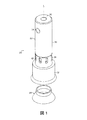
図1及び2は、燃焼バーナー(20)がガス燃料だけでなく、液体燃料を燃焼するのに用いられることを示す。バーナー(20)は、外部燃焼エンジン、化学プロセッサ及びヒーターのようなシステムに用いられる。ここで説明された通り、液体燃料の燃焼及びガス燃料の燃焼間の切り替えは、バーナー(20)やバーナーを含むシステム(例えば、ハードウェアを追加したり除去することで)を変更せず行うことができる。また、バーナー(20)は、低排出で広範囲な燃料を燃焼することができる。例えば、灯油の燃焼は、排気ガスで4%の過剰酸素(略0.8π)下でも、略500ppmCO以下の排出が可能である。100ppmCO以下のより低い排出は、フレームで更に多い過剰エア(例えば、0.7〜0.75π)とともに可能である。
1 and 2 show that the combustion burner (20) can be used to burn liquid fuel as well as gas fuel. The
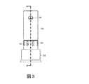
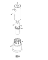
図3、4及び5を参照すると、一般的にバーナー(20)は、ハウジング(22)とハウジング内部の蒸発器(40)を含む。作動の間、燃料は蒸発器(40)(例えば、液体燃料を蒸発させる)に導かれ、ガス燃料とエアは、蒸発器とハウジング(22)との間に規定された混合領域(50)で混合される。混合された燃料とエアは、バーナー排出口(28)で燃焼される。より具体的に、ハウジング(22)は、上部ボディ(30)と上部ボディに結合される下部ボディ(32)を含む。上部ボディ(30)は、燃料注入口(34)と上部ボディの縦軸(L)に沿って延長される通路(36)を含む。下部ボディ(32)は、下部ボディの外周に沿って配列される複数のエア注入口(38)を含む。図1及び2に示された通り、バーナー(20)は、バーナー排出口(28)を設定する円錐形状の端部(24)[下部ボディ(32)と一つに形成できる]を含む。ハウジング(22)内で蒸発器(40)(図示された通り、開口端と閉鎖端を有する円筒ボディ)は、通路(36)及びバーナー排出口(28)と同軸にある。蒸発器(40)とハウジング(22)との間にガス燃料とエアが燃焼前に混合されるエア/ガス燃料混合領域(50)(図示された通り、円筒空間)がある。蒸発器(40)は、蒸発器の外周に沿って位置する複数の燃料排出口(42)(図示された通り、丸い開口)を有する。図2に示した通り、蒸発器(40)内に、バーナー(20)は、使用中に、液体燃料を蒸発させ得る熱伝導性多孔質材料(44)(例えば、発泡金属)と、多孔質材料を加熱するように構成されたグロープラグ(glow plug)(46)を更に含む。一部の実施形態で、バーナー(20)は多孔質材料(44)を含まないが、グロープラグ(46)を含み得る。 Referring to FIGS. 3, 4 and 5, the burner (20) generally includes a housing (22) and an evaporator (40) inside the housing. During operation, fuel is directed to the evaporator (40) (e.g., to evaporate liquid fuel), and gaseous fuel and air are mixed in the mixing zone (50) defined between the evaporator and the housing (22). Mixed. The mixed fuel and air are burned at the burner outlet (28). More specifically, the housing (22) includes an upper body (30) and a lower body (32) coupled to the upper body. The upper body (30) includes a fuel inlet (34) and a passageway (36) extending along the longitudinal axis (L) of the upper body. The lower body (32) includes a plurality of air inlets (38) arranged along the outer periphery of the lower body. As shown in FIGS. 1 and 2, the burner (20) includes a conical end (24) [can be formed with the lower body (32)] that defines a burner outlet (28). Within the housing (22), the evaporator (40) (as shown, a cylindrical body having an open end and a closed end) is coaxial with the passage (36) and the burner outlet (28). Between the evaporator (40) and the housing (22) is an air / gas fuel mixing region (50) (cylindrical space as shown) where gas fuel and air are mixed before combustion. The evaporator (40) has a plurality of fuel discharge ports (42) (round openings as shown) located along the outer periphery of the evaporator. As shown in FIG. 2, in the evaporator (40), the burner (20) includes a thermally conductive porous material (44) (e.g., foam metal) capable of evaporating liquid fuel during use, and porous It further includes a glow plug (46) configured to heat the material. In some embodiments, the burner (20) does not include a porous material (44), but may include a glow plug (46).
作動の間、液体燃料(ディーゼル燃料等)又はガス燃料(プロパン等)は、バーナー排出口(28)での燃焼のために燃料注入口(34)を通じて導入される。より具体的に、液体燃料を燃焼するための「液体モード」においてグロープラグ(46)は、液体燃料を蒸発させる蒸発熱を提供するのに用いられる多孔質材料(44)を加熱する開始点で活性化される。一部の実施形態においてグロープラグ(46)は、開始点での完全な蒸発を確かにするために、燃料導入前に5分間、また点火後5分間まで活性化され、液体燃料の燃焼が進行するにつれ、蒸発熱は、バーナー(20)に近い熱いガスから、燃焼と対流からの放射によりさらに生成できる。グロープラグ(46)と多孔質材料(44)が十分に加熱され液体燃料を蒸発させると、液体燃料は燃料注入口(34)を通じてバーナー(20)に導入される。液体燃料は、液体燃料がガス燃料に蒸発する多孔質材料(44)にフローイングし、燃料排出口(42)を通じてフローイングする。同時に、エアは、エア注入口(38)(例えば、ファン、ブロワー又はコンプレッサーにより加圧される)を通じてフローイングされ、このエアは、バーナー排出口(28)近傍で燃焼前に混合領域(50)で燃料排出口(42)から出るガス燃料と混合される。フレームは、排出口(28)近傍の、例えば、スパークプラグ、グロープラグ又は熱い表面点火装置を有する点火源によって初めて点火される。バーナー(20)が点火されると、点火源は燃焼を維持するためにそれ以上要求されない。グロープラグ(46)は、例えば、点火後約5分後に非活性化できる。 During operation, liquid fuel (such as diesel fuel) or gas fuel (such as propane) is introduced through the fuel inlet (34) for combustion at the burner outlet (28). More specifically, in the “liquid mode” for burning liquid fuel, the glow plug (46) is the starting point for heating the porous material (44) used to provide the evaporation heat that evaporates the liquid fuel. Activated. In some embodiments, the glow plug (46) is activated for 5 minutes prior to fuel introduction and up to 5 minutes after ignition to ensure complete evaporation at the starting point and liquid fuel combustion proceeds. As such, heat of evaporation can be further generated from the hot gas near the burner (20) by radiation from combustion and convection. When the glow plug (46) and the porous material (44) are sufficiently heated to evaporate the liquid fuel, the liquid fuel is introduced into the burner (20) through the fuel inlet (34). The liquid fuel flows to the porous material (44) from which the liquid fuel evaporates into the gas fuel, and flows through the fuel discharge port (42). At the same time, air is flowed through an air inlet (38) (e.g., pressurized by a fan, blower or compressor), this air is mixed near the burner outlet (28) before combustion in the mixing zone (50). And mixed with the gaseous fuel exiting from the fuel outlet (42). The frame is ignited for the first time by an ignition source, for example having a spark plug, glow plug or hot surface igniter, near the outlet (28). When the burner (20) is ignited, no further ignition source is required to maintain combustion. The glow plug (46) can be deactivated, for example, about 5 minutes after ignition.
ガス燃料を燃焼させるための「ガスモード」で、ガス燃料は、上述した液体燃料の流路と略同一の流路を通じてフローイングする。より具体的に、ガス燃料は、燃料注入口(34)を通じてバーナー(20)に導入される。ガス燃料は、多孔質材料(44)と接触し、少量の熱が吸収できるが、燃料は、液体燃料のような相変化を経験しない。その後、ガス燃料は、燃料排出口(42)を通じフローイングされる。その後、エア注入口(38)を通じて導入されるエアは、混合領域(50)で燃料排出口(42)を出るガス燃料と混合され、このエア及び燃料混合物は、バーナー排出口(28)近くで燃焼され、「液体モード」の作動で説明された通り、点火源によって初めて点火される。 In the “gas mode” for burning the gas fuel, the gas fuel flows through substantially the same flow path as the liquid fuel flow path described above. More specifically, the gas fuel is introduced into the burner (20) through the fuel inlet (34). Although the gas fuel contacts the porous material (44) and can absorb a small amount of heat, the fuel does not experience phase changes like liquid fuel. Thereafter, the gas fuel flows through the fuel discharge port (42). The air introduced through the air inlet (38) is then mixed with the gaseous fuel leaving the fuel outlet (42) in the mixing zone (50), and this air and fuel mixture is near the burner outlet (28). It is burned and ignited for the first time by an ignition source as described in the “liquid mode” operation.
図2を再度参照すると、蒸発器(40)内とその閉鎖端近くで、バーナー(20)は熱交換器と蒸発表面として機能する多孔質材料(44)を含む。ガス燃料は、熱い表面からガスへの熱伝達が、液体への熱伝達よりはるかに効果的でないので、作動に顕著な熱伝達なく蒸発器(40)を出入することができる。しかし、液体燃料とともに、多孔質材料(44)は、表面の蒸発ホットスポットの制限、熱の分散で温度の均一性を増大することができ、この均一温度で拡張された表面領域に提供できる。作動の間、燃料が底面上の多孔質材料によって蒸発すると、多孔質材料(44)の最も熱い表面に到達しない。大量の燃料蒸留液の軽い部分であるほど、より低温でより速く蒸発でき、燃料の過熱とコークス形成は、このメカニズムによって制限され得る。さらに、この蒸発接近法においてコークス形成は、バーナー(20)に悪い影響を与えない。事実、一部の非常に遅いコークスは、多孔質材料(44)の大きく開放された体積と表面積のため、コークス形成が燃料蒸発にさらに影響を与える前に構成され得る。多孔質材料(44)は、バーナー(20)の寿命を増加させるのに有用であり得る。また、多孔質材料(44)は、コークスが最も熱い表面に形成されると、熱が表面から離れて形成される蒸気に十分遠くまで伝わるので、優れた熱伝導性を提供する。 Referring again to FIG. 2, in the evaporator (40) and near its closed end, the burner (20) includes a heat exchanger and a porous material (44) that functions as the evaporation surface. Gaseous fuel can enter and exit the evaporator (40) without significant heat transfer in operation because heat transfer from the hot surface to the gas is much less effective than heat transfer to the liquid. However, along with the liquid fuel, the porous material (44) can increase the uniformity of temperature by limiting the evaporation hot spots on the surface, the distribution of heat, and can provide an extended surface area at this uniform temperature. During operation, as the fuel evaporates by the porous material on the bottom surface, it does not reach the hottest surface of the porous material (44). The lighter portion of the bulk fuel distillate can evaporate faster at lower temperatures, and fuel overheating and coke formation can be limited by this mechanism. Furthermore, coke formation in this evaporation approach does not adversely affect the burner (20). In fact, some very slow coke can be configured before coke formation further affects fuel evaporation due to the large open volume and surface area of the porous material (44). The porous material (44) may be useful for increasing the life of the burner (20). The porous material (44) also provides excellent thermal conductivity when coke is formed on the hottest surface, since heat is transferred far enough to the vapor formed away from the surface.
多孔質材料(44)は、高表面積を有する高温耐性、熱伝導性の物質で形成できる。例えば、バーナーのコンピュータによる流体力学分析は、バーナーが灯油燃料により作動されるとき、600℃に近い発泡金属多孔質材料の最大温度を示す。結果的に、一部の実施形態で多孔質材料(44)は、酸化及び分解のような逆効果なしで、少なくとも略600℃、少なくとも略800℃の温度で耐えることができる。多孔質材料(44)は、略60%から略95%までの空隙率を有することができる。多孔質材料(44)のセルサイズは、略10ppi(インチ当りの気孔)〜100ppiを有することができるので、多孔質材料に悪い影響を与えるフローイング抵抗なしで、高表面積の利点を得る。多孔質材料(44)の構造は、例えば、多孔質材料の一部がコークスでいっぱいになり始めると、液体燃料を蒸発させるのに要求される熱を提供するように残っている蒸発表面を提供する。多孔質材料(44)の例は、ステンレススチール又は鉄クロム(FeCr)合金を含む(例えば、完全に形成される)発泡金属を含む。 The porous material (44) can be formed of a high temperature resistant, heat conductive material having a high surface area. For example, burner computer hydrodynamic analysis shows the maximum temperature of the foam metal porous material close to 600 ° C. when the burner is operated with kerosene fuel. As a result, in some embodiments, the porous material (44) can withstand temperatures of at least about 600 ° C. and at least about 800 ° C. without adverse effects such as oxidation and decomposition. The porous material (44) can have a porosity of about 60% to about 95%. The cell size of the porous material (44) can have approximately 10 ppi (pores per inch) to 100 ppi, thus obtaining the advantage of high surface area without the flow resistance that adversely affects the porous material. The structure of the porous material (44) provides the remaining evaporation surface to provide the heat required to evaporate the liquid fuel, for example, when a portion of the porous material begins to fill with coke To do. Examples of porous material (44) include foam metal including (eg, fully formed) stainless steel or iron chromium (FeCr) alloy.
図2を続けて参照すると、ガス燃料が(導かれたり、蒸発した後)、燃料排出口(42)を出るとき、ガス燃料は、エア注入口(38)を通じて入るエアと混合される。図示された通り、ガス燃料とエアとの間の混合を増加させるために、燃料排出口(42)とエア注入口(38)は、一つ以上の燃料排出口の少なくとも一部が、軸(L)に沿う一つ以上のエア注入口の少なくとも一部とオーバーラップするように縦軸(L)の方向に沿って整列される。図2に示した通り、燃料排出口(42)は、エア注入口(38)と完全にオーバーラップする。このオーバーラップは、ガス燃料が蒸発器(40)を出ていくときに入ってくるエアがガス燃料をスワイプ(swipe)できるようにし、優れた混合を提供する。一部の実施形態で、エア注入口(38)は、縦軸(L)に沿う燃料排出口(42)の寸法と同一であるか、より大きな縦軸(L)に沿う寸法を有する。一部の実施形態で、エア注入口(38)と燃料排出口(42)は、縦軸(L)に沿ってオーバーラップされない。例えば、燃料排出口(42)は、バーナーに注入されるエアの流路に沿ってエア注入口(38)の下流側に位置し得る。 Continuing to refer to FIG. 2, when the gaseous fuel exits the fuel outlet (42) (after being directed or evaporated), the gaseous fuel is mixed with the air entering through the air inlet (38). As shown, in order to increase mixing between gaseous fuel and air, the fuel outlet (42) and the air inlet (38) have at least a portion of one or more fuel outlets on the shaft ( Aligned along the direction of the longitudinal axis (L) to overlap at least a portion of one or more air inlets along L). As shown in FIG. 2, the fuel discharge port (42) completely overlaps the air injection port (38). This overlap allows the incoming air as the gas fuel exits the evaporator (40) to swipe the gas fuel and provides excellent mixing. In some embodiments, the air inlet (38) has the same dimension as the fuel outlet (42) along the longitudinal axis (L) or a larger dimension along the longitudinal axis (L). In some embodiments, the air inlet (38) and the fuel outlet (42) are not overlapped along the longitudinal axis (L). For example, the fuel discharge port (42) may be located downstream of the air injection port (38) along the flow path of air injected into the burner.
混合を更に増加させるために、エア注入口(38)を傾けて入ってくるエアをバーナー(20)の外周へ非垂直角度で向かわせる。例えば、エア注入口(38)を規定する下部ボディ(32)の壁は、入ってくるエアが、バーナー(20)の外周に接線方向に向かうように傾けて、エアと混合領域(50)のエア/ガス燃料混合物を旋回させることを助ける。
一部の実施形態で、図5を参照すると、混合領域(50)で混合を更に増加させるため、バーナー(20)は、エア/ガス燃料を縦軸(L)に対して傾斜したり曲がった方向(例えば、混合領域(50)の外周に接する)に向かわせるのに役立つ混合領域での構造的特徴を含む。図示された通り、バーナー(20)は、蒸発器(40)の外周から延長される複数の旋回羽根(60)を含む。
To further increase mixing, the air inlet (38) is tilted to direct incoming air to the outer periphery of the burner (20) at a non-vertical angle. For example, the wall of the lower body (32) that defines the air inlet (38) is inclined so that the incoming air is tangentially directed to the outer periphery of the burner (20), and the Help swirl the air / gas fuel mixture.
In some embodiments, referring to FIG. 5, to further increase mixing in the mixing zone (50), the burner (20) tilts or bends the air / gas fuel relative to the longitudinal axis (L). It includes structural features in the mixing region that help direct the direction (eg, touching the outer periphery of the mixing region (50)). As shown, the burner (20) includes a plurality of swirl vanes (60) extending from the outer periphery of the evaporator (40).
エア注入口(38)を通じて入るエアの傾斜した方向及び/又は混合領域(50)の構造的特徴は、バーナー(20)でのエア/ガス燃料旋回を発生させることを助けることができる。旋回は応力層と強い混合ストリームが提供できるので、灯油やDF-2ディーゼル燃料のような低い拡散率を有する大きな燃料分子に対して特に重要になり得る。また、旋回は広範囲なフレームの速度や等価率において作動するフレーム安定メカニズムも提供できる。例えば、灯油は略0.6から略0.9までの等価率で燃焼できる。同一のバーナーは、2つの燃料のフレーム速度は同一でなくても、略0.6から0.9までの等価率を有するプロパンにより作動できる。一部の実施形態で、ガス燃料とエアが混合されると、燃焼工程はバーナー排出口(28)で略0.2から略1.5まで(略0.5から略0.7までのような)の旋回数(SN)で旋回安定したフレームに安定化し、SNは軸モメンタムの軸流動に対する各運動量の軸流動の割合で定義される。 The slanted direction of air entering through the air inlet (38) and / or the structural features of the mixing zone (50) can help generate air / gas fuel swirl at the burner (20). Swirl can be particularly important for large fuel molecules with low diffusivity, such as kerosene and DF-2 diesel fuel, as they can provide a stress layer and a strong mixing stream. Swing can also provide a frame stabilization mechanism that operates over a wide range of frame speeds and equivalence rates. For example, kerosene can burn at an equivalent rate from about 0.6 to about 0.9. The same burner can be operated with propane having an equivalent ratio of approximately 0.6 to 0.9, even though the flame speeds of the two fuels are not the same. In some embodiments, when the gas fuel and air are mixed, the combustion process is performed at the burner outlet (28) from about 0.2 to about 1.5 (such as from about 0.5 to about 0.7) number of turns (S N ), And the S N is defined as the ratio of the axial flow of each momentum to the axial flow of the axial momentum.
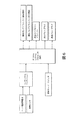
図6と図7を参照すると、ここで説明されるバーナー(20)の実施形態は、適用可能なコントロールシステム(100)に用いられる。例えば、適用可能なコントロールシステムは、ガスと液体燃料で燃焼工程をコントロールする外部燃焼エンジンとともに利用できる。図示された通り、コントロールシステム(100)は、エアと燃料の供給をコントロールするためのメカニズムを含む。調整バルブ(102)は、ガス燃料(103)のフローをコントロールするように利用できる。ポンプ(104)は、液体燃料(105)をコントロールするのに利用できる。ブロワー(106)は、システムに燃焼エアを供給するために利用できる。図示された通り、システム(100)は、2つの連結点を有する燃料供給ライン(108、110)を含む。一つは液体燃料(108)のためのものであり、もう一つはガス燃料(110)のためのものである。ラインのうち一つを作動させる3方向バルブ(112)は、バーナー(20)の上流側のシステム(100)で利用できる。一部の実施形態で、バルブ(112)は、バルブが選択モードにある肯定指示を提供する、スイッチのようなメカニズムを有する。燃料選択器のスイッチは、バルブ(112)がシステム(100)の適切な作動のために選択されるガスモードにある肯定指示が提供できる。 With reference to FIGS. 6 and 7, the embodiment of the burner (20) described herein is used in an applicable control system (100). For example, applicable control systems can be used with external combustion engines that control the combustion process with gas and liquid fuel. As shown, the control system (100) includes a mechanism for controlling the supply of air and fuel. The regulating valve (102) can be used to control the flow of gas fuel (103). The pump (104) can be used to control the liquid fuel (105). A blower (106) can be utilized to provide combustion air to the system. As shown, the system (100) includes a fuel supply line (108, 110) having two connection points. One is for liquid fuel (108) and the other is for gas fuel (110). A three-way valve (112) that activates one of the lines is available in the system (100) upstream of the burner (20). In some embodiments, the valve (112) has a switch-like mechanism that provides an affirmative indication that the valve is in a select mode. The fuel selector switch can provide an affirmative indication that the valve (112) is in the gas mode selected for proper operation of the system (100).
作動の間、ユーザー設定スイッチは、コントロールシステム(100)に「液体モード」又は「ガスモード」を作動させ得る。システム(100)のモードは、例えば、燃料とエアのための供給システムを含むバーナー(20)のコントロールを作動させ得る。燃料フローは、温度設定ポイントとバーナー(20)の温度測定(116)からのフィードバックシグナルに基づいて設定できる。エアフローイングは、燃料フローイングに基づく設定ポイントと、燃焼混合物の化学量論を示すフィードバックシグナルに基づいて設定できる。燃料率に基づいて「フィード-フォワード」用語と結合したセンサ(114)からの「フィードバック」用語を有するこのハイブリッドコントロールシステムは、例えば「フィードバック」の応答にのみ基づくコントロールシステムに関する安定性を向上させ得る。ユーザーは、システム(100)の所望のモードを作動させたり選択でき、バーナー(20)は、液体とガス燃料とに非常に類似して作動できるので、同一のセンサ(114、116)は、両方モードにフィードバックのために利用できる。 During operation, the user setting switch may cause the control system (100) to activate “liquid mode” or “gas mode”. The mode of the system (100) may activate the control of the burner (20) including, for example, a supply system for fuel and air. The fuel flow can be set based on the temperature set point and the feedback signal from the temperature measurement (116) of the burner (20). Airflow can be set based on a set point based on fuel flow and a feedback signal indicating the stoichiometry of the combustion mixture. This hybrid control system with a “feedback” term from the sensor (114) combined with a “feed-forward” term based on fuel rate can improve stability for a control system based solely on a “feedback” response, for example . The user can activate or select the desired mode of the system (100), and the burner (20) can operate very similar to liquid and gas fuel, so the same sensor (114, 116) is both Available for feedback to mode.
燃料とエアに対するフィードバックシステムは、両方のモードに対して同一のハードウェアを利用できるが、モードに応じて異なる設定ポイントを有する。例えば、外部燃焼エンジンの場合、一つは燃料率をコントロールしてエンジンの特定のボディ温度が維持できる。温度は、例えば、熱電対や抵抗温度検出器(RTD)によって測定できる。温度はモードが液体又はガス燃料であるかに応じて変わり得る。エアの量は、例えば自動酸素センサ、一酸化炭素センサ又はフレーム整流センサような化学量論のセンサからのフィードバックを用いてコントロールできる。酸素センサの場合、消費される酸素の量は予め指定されるか、液体燃料とガス燃料に応じて異なり得る。フィードバック値に対する他の設定は、液体燃料が燃料されるのであれガス燃料が燃焼されるのであれ、クリーンな排出を維持するために、システム(100)のモードによって指定され得る。フレームの速度は、燃料(天然ガス、プロパン、ブタン及びガソリン、灯油又はディーゼル等の液体燃料を含むガス燃料)の各モード内で更に類似するので、一つの酸素設定のみ各モードに対し必要であり、システム(100)に対するモードは一つのスイッチで指定され得る。 The fuel and air feedback system can utilize the same hardware for both modes, but has different set points depending on the mode. For example, in the case of an external combustion engine, one can control the fuel rate to maintain a specific body temperature of the engine. The temperature can be measured by, for example, a thermocouple or a resistance temperature detector (RTD). The temperature can vary depending on whether the mode is liquid or gas fuel. The amount of air can be controlled using feedback from a stoichiometric sensor such as an automatic oxygen sensor, a carbon monoxide sensor or a flame rectification sensor. In the case of an oxygen sensor, the amount of oxygen consumed can be pre-specified or can vary depending on the liquid fuel and the gas fuel. Other settings for the feedback value may be specified by the mode of the system (100) to maintain clean emissions whether liquid fuel or gas fuel is burned. The speed of the flame is more similar within each mode of fuel (gas fuels including natural gas, propane, butane and liquid fuel such as gasoline, kerosene or diesel), so only one oxygen setting is required for each mode. The mode for the system (100) can be specified with one switch.
多数の実施形態が記載されているが、本発明が限定されることはない。
例として、予熱されたエアは、例えばバーナーエアが回復すれば、蒸発工程を促進できもする。例えば、バーナーエアが排気ガスにより回復され得、回復の程度に応じて600℃に近接する温度に到達し得る。この温度のエアは燃料の蒸発工程を促進できる。
他の実施例として、図2を参照すると、バーナー排出口(28)は、略0°から略120°まで(略40°から略80°までのような)の角度(α)を有することができる。円錐角度が大きければ、半径方向へフレームを延長することができ、ある程度の熱がフレームから加熱されるボディに伝達されるのみならず、フレームの安定にも影響を与え得る。
A number of embodiments have been described, but the invention is not limited.
As an example, preheated air can also facilitate the evaporation process if, for example, the burner air is restored. For example, the burner air can be recovered by exhaust gas and reach a temperature close to 600 ° C. depending on the degree of recovery. This temperature of air can accelerate the fuel evaporation process.
As another example, referring to FIG. 2, the burner outlet (28) may have an angle (α) of approximately 0 ° to approximately 120 ° (such as approximately 40 ° to approximately 80 °). it can. If the cone angle is large, the frame can be extended in the radial direction, and not only can some heat be transferred from the frame to the heated body, but it can also affect the stability of the frame.
一部の実施形態で、バーナーは多孔質材料(44)及び/又はグロープラグ(46)が選択された作動間隔後に容易に代替(フィルタと類似する)できるように考案できる。例えば、グロープラグ(46)と多孔質材料(44)は、パッケージを除去したりインストールするためのグロープラグのスレッドを用いることで、共に除去したり代替できる一つの予め組立てられたパッケージのように製造され得る。 In some embodiments, the burner can be devised so that the porous material (44) and / or the glow plug (46) can be easily replaced (similar to a filter) after a selected operating interval. For example, the glow plug (46) and porous material (44) are like a pre-assembled package that can be removed or replaced together by using a glow plug thread to remove or install the package. Can be manufactured.
追加的に又は代案として、バーナーの側部に位置するエア注入口を通じてエアをバーナーへ注入するために、エアはバーナーの端部から導入され得る。例えば、バーナーはグロープラグを同軸に囲み、蒸発器と流体連通される環状通路を含むことができる。グロープラグのない実施形態では、エアは通路(36)を通じて導入され得る。
「上部」、「下部」及び「底部」のような位置を示す用語は、図面に関連して便宜上用いられたもので限定されはしない。
Additionally or alternatively, air can be introduced from the end of the burner to inject air into the burner through an air inlet located on the side of the burner. For example, the burner can include an annular passage coaxially surrounding the glow plug and in fluid communication with the evaporator. In embodiments without a glow plug, air may be introduced through the passage (36).
Terms indicating positions such as “top”, “bottom” and “bottom” are used for convenience in connection with the drawings and are not limited.
請求の範囲内において、さらに他の実施形態が存在し得る。 Still other embodiments may exist within the scope of the claims.
Claims (61)
ガス燃料を含む第2のソース、及び
前記第1及び第2のソースに連結され、前記液体燃料と前記ガス燃料とに選択的に連通され前記燃料を収容する燃焼バーナーを含むシステムであって、
前記バーナーは、当該バーナー又は前記システムの変更なく、前記液体燃料の燃焼と前記ガス燃料の燃焼との間でスイッチングできることを特徴とする燃料燃焼システム。 A first source containing liquid fuel,
A system comprising: a second source containing gas fuel; and a combustion burner coupled to the first and second sources, selectively in communication with the liquid fuel and the gas fuel and containing the fuel,
The fuel combustion system characterized in that the burner can be switched between the combustion of the liquid fuel and the combustion of the gas fuel without changing the burner or the system.
前記燃料注入口を通じて前記第1のフェイズと異なる第2のフェイズにある第2の燃料を導入するステップを含む燃焼方法であって、
前記バーナーへの前記第2の燃料の導入は、前記バーナー又は前記燃焼システムを変更せずに行うことを特徴とする燃焼方法。 Introducing a first fuel in a first phase through a fuel inlet of a burner of a combustion system; and introducing a second fuel in a second phase different from the first phase through the fuel inlet A combustion method comprising:
2. The combustion method according to claim 1, wherein the introduction of the second fuel into the burner is performed without changing the burner or the combustion system.
前記燃料注入口と流体連通される蒸発器キャビティ、
前記蒸発器キャビティと流体連通される燃料排出口、及び
前記燃料排出口と流体連通されるエア注入口を含むバーナーであって、
前記エア注入口は、前記バーナーの半径方向に沿って前記燃料排出口の少なくとも一部とオーバーラップすることを特徴とするバーナー。 Fuel inlet,
An evaporator cavity in fluid communication with the fuel inlet;
A burner including a fuel outlet in fluid communication with the evaporator cavity, and an air inlet in fluid communication with the fuel outlet;
The burner, wherein the air inlet overlaps at least a part of the fuel outlet along a radial direction of the burner.
前記燃料注入口と流体連通される蒸発器キャビティ、
前記蒸発器キャビティと流体連通される燃料排出口、
前記燃料排出口と流体連通されるエア注入口、及び
前記エア注入口の下流側に位置し、前記蒸発器キャビティを囲む空間、を含むことを特徴とするバーナー。 Fuel inlet,
An evaporator cavity in fluid communication with the fuel inlet;
A fuel outlet in fluid communication with the evaporator cavity;
A burner comprising: an air inlet that is in fluid communication with the fuel outlet; and a space that is located downstream of the air inlet and surrounds the evaporator cavity.
Applications Claiming Priority (3)
| Application Number | Priority Date | Filing Date | Title |
|---|---|---|---|
| US93191907P | 2007-05-25 | 2007-05-25 | |
| US60/931,919 | 2007-05-25 | ||
| PCT/US2008/064695 WO2008147987A1 (en) | 2007-05-25 | 2008-05-23 | Fuel combustion |
Publications (2)
| Publication Number | Publication Date |
|---|---|
| JP2010528255A true JP2010528255A (en) | 2010-08-19 |
| JP5563976B2 JP5563976B2 (en) | 2014-07-30 |
Family
ID=40075513
Family Applications (1)
| Application Number | Title | Priority Date | Filing Date |
|---|---|---|---|
| JP2010510439A Expired - Fee Related JP5563976B2 (en) | 2007-05-25 | 2008-05-23 | Fuel combustion system, combustion method and burner |
Country Status (7)
| Country | Link |
|---|---|
| US (1) | US8221115B2 (en) |
| EP (1) | EP2153042B1 (en) |
| JP (1) | JP5563976B2 (en) |
| KR (1) | KR101591317B1 (en) |
| CA (1) | CA2688307C (en) |
| ES (1) | ES2691709T3 (en) |
| WO (1) | WO2008147987A1 (en) |
Cited By (2)
| Publication number | Priority date | Publication date | Assignee | Title |
|---|---|---|---|---|
| JP2014514521A (en) * | 2011-01-20 | 2014-06-19 | カスケード デザイン,インク. | Combined metering jet of fuel and oxidant, system and method for metering fuel and oxidant simultaneously |
| JP2015061998A (en) * | 2007-10-15 | 2015-04-02 | エンウェイブ コーポレイションEnwave Corporation | Apparatus for microwave vacuum-drying of organic material |
Families Citing this family (14)
| Publication number | Priority date | Publication date | Assignee | Title |
|---|---|---|---|---|
| TR200904537A2 (en) * | 2009-06-10 | 2009-11-23 | Özti̇ryaki̇ler Madeni̇ Eşya Sanayi̇ Ve Ti̇caret A.Ş. | Electronically controlled liquid, gas fuel burner |
| CN102330991A (en) * | 2011-05-31 | 2012-01-25 | 黑龙江建龙钢铁有限公司 | Coal gas diffusion device capable of diffusing a plurality of coal gases |
| US9689615B2 (en) * | 2012-08-21 | 2017-06-27 | Uop Llc | Steady state high temperature reactor |
| US20140058168A1 (en) * | 2012-08-21 | 2014-02-27 | Uop Llc | Methane Conversion Apparatus and Process with Improved Mixing Using a Supersonic Flow Reactor |
| US9707530B2 (en) * | 2012-08-21 | 2017-07-18 | Uop Llc | Methane conversion apparatus and process using a supersonic flow reactor |
| US10029957B2 (en) * | 2012-08-21 | 2018-07-24 | Uop Llc | Methane conversion apparatus and process using a supersonic flow reactor |
| US9656229B2 (en) * | 2012-08-21 | 2017-05-23 | Uop Llc | Methane conversion apparatus and process using a supersonic flow reactor |
| US10160697B2 (en) * | 2012-08-21 | 2018-12-25 | Uop Llc | Methane conversion apparatus and process using a supersonic flow reactor |
| US10281146B1 (en) * | 2013-04-18 | 2019-05-07 | Astec, Inc. | Apparatus and method for a center fuel stabilization bluff body |
| US9638413B2 (en) | 2014-03-05 | 2017-05-02 | Progreen Labs, Llc | Treatment device of a heating system |
| US9488373B2 (en) | 2014-03-06 | 2016-11-08 | Progreen Labs, Llc | Treatment device of a heating system |
| US9593857B2 (en) | 2014-03-07 | 2017-03-14 | ProGreen Labs, LLC. | Heating system |
| TWM554151U (en) * | 2017-10-02 | 2018-01-11 | Shang Chtao Precision Co Ltd | Vaporization tube of kerosene lamp |
| CN108167827B (en) * | 2017-12-29 | 2024-04-30 | 安徽醇生新能源科技有限公司 | Alcohol-based fuel combustion device |
Citations (8)
| Publication number | Priority date | Publication date | Assignee | Title |
|---|---|---|---|---|
| GB1122929A (en) * | 1966-09-27 | 1968-08-07 | Sun Oil Co | Method of making a normally liquid fuel interchangeable with gas |
| JPS5649814A (en) * | 1979-09-28 | 1981-05-06 | Sanyo Electric Co Ltd | Control circuit for combustion unit |
| JPS56124820A (en) * | 1980-03-05 | 1981-09-30 | Toshiba Corp | Combustion device |
| JPS56168022A (en) * | 1980-05-28 | 1981-12-24 | Toshiba Corp | Burner employing different kinds of fuel |
| US5400969A (en) * | 1993-09-20 | 1995-03-28 | Keene; Christopher M. | Liquid vaporizer and diffuser |
| US5680766A (en) * | 1996-01-02 | 1997-10-28 | General Electric Company | Dual fuel mixer for gas turbine combustor |
| JP2001050508A (en) * | 1999-03-24 | 2001-02-23 | Denso Corp | Catalyst combustion apparatus with vaporization function |
| US20050250061A1 (en) * | 2002-09-04 | 2005-11-10 | Rainer Lochschmied | Burner controller and adjusting method for a burner controller |
Family Cites Families (4)
| Publication number | Priority date | Publication date | Assignee | Title |
|---|---|---|---|---|
| US1865056A (en) | 1928-07-19 | 1932-06-28 | Doherty Res Co | Flambeau type of burner |
| US3308868A (en) * | 1965-05-05 | 1967-03-14 | Comb Efficiency Corp | Combination oil and gas burner construction |
| US3291191A (en) * | 1966-01-28 | 1966-12-13 | Sun Oil Co | Method of making a normally liquid fuel interchangeable with gas |
| DE10360458A1 (en) | 2003-12-22 | 2005-07-28 | J. Eberspächer GmbH & Co. KG | The fuel cell system |
-
2008
- 2008-05-23 JP JP2010510439A patent/JP5563976B2/en not_active Expired - Fee Related
- 2008-05-23 ES ES08769699.3T patent/ES2691709T3/en active Active
- 2008-05-23 CA CA2688307A patent/CA2688307C/en active Active
- 2008-05-23 US US12/601,802 patent/US8221115B2/en not_active Expired - Fee Related
- 2008-05-23 EP EP08769699.3A patent/EP2153042B1/en active Active
- 2008-05-23 WO PCT/US2008/064695 patent/WO2008147987A1/en active Application Filing
- 2008-05-23 KR KR1020097026260A patent/KR101591317B1/en not_active Expired - Fee Related
Patent Citations (8)
| Publication number | Priority date | Publication date | Assignee | Title |
|---|---|---|---|---|
| GB1122929A (en) * | 1966-09-27 | 1968-08-07 | Sun Oil Co | Method of making a normally liquid fuel interchangeable with gas |
| JPS5649814A (en) * | 1979-09-28 | 1981-05-06 | Sanyo Electric Co Ltd | Control circuit for combustion unit |
| JPS56124820A (en) * | 1980-03-05 | 1981-09-30 | Toshiba Corp | Combustion device |
| JPS56168022A (en) * | 1980-05-28 | 1981-12-24 | Toshiba Corp | Burner employing different kinds of fuel |
| US5400969A (en) * | 1993-09-20 | 1995-03-28 | Keene; Christopher M. | Liquid vaporizer and diffuser |
| US5680766A (en) * | 1996-01-02 | 1997-10-28 | General Electric Company | Dual fuel mixer for gas turbine combustor |
| JP2001050508A (en) * | 1999-03-24 | 2001-02-23 | Denso Corp | Catalyst combustion apparatus with vaporization function |
| US20050250061A1 (en) * | 2002-09-04 | 2005-11-10 | Rainer Lochschmied | Burner controller and adjusting method for a burner controller |
Cited By (2)
| Publication number | Priority date | Publication date | Assignee | Title |
|---|---|---|---|---|
| JP2015061998A (en) * | 2007-10-15 | 2015-04-02 | エンウェイブ コーポレイションEnwave Corporation | Apparatus for microwave vacuum-drying of organic material |
| JP2014514521A (en) * | 2011-01-20 | 2014-06-19 | カスケード デザイン,インク. | Combined metering jet of fuel and oxidant, system and method for metering fuel and oxidant simultaneously |
Also Published As
| Publication number | Publication date |
|---|---|
| WO2008147987A1 (en) | 2008-12-04 |
| CA2688307C (en) | 2016-05-17 |
| KR101591317B1 (en) | 2016-02-03 |
| EP2153042A1 (en) | 2010-02-17 |
| CA2688307A1 (en) | 2008-12-04 |
| US8221115B2 (en) | 2012-07-17 |
| JP5563976B2 (en) | 2014-07-30 |
| EP2153042B1 (en) | 2018-07-25 |
| KR20100022048A (en) | 2010-02-26 |
| ES2691709T3 (en) | 2018-11-28 |
| US20100216079A1 (en) | 2010-08-26 |
| EP2153042A4 (en) | 2015-10-28 |
Similar Documents
| Publication | Publication Date | Title |
|---|---|---|
| JP5563976B2 (en) | Fuel combustion system, combustion method and burner | |
| JP4029179B2 (en) | Processes and apparatus for the combustion of liquid fuels | |
| US20040058290A1 (en) | Self-sustaining premixed pilot burner for liquid fuels | |
| CA1303477C (en) | Catalytic combustion device | |
| JP5279725B2 (en) | Heating device including catalytic combustion of liquid fuel | |
| EP3152490B1 (en) | Non-symmetrical low nox burner apparatus and method | |
| JP3675163B2 (en) | Tubular flame burner | |
| US20050079458A1 (en) | Heater with an atomizer nozzle | |
| JP3873119B2 (en) | In-cylinder swirl combustor | |
| JP5525855B2 (en) | Combustion device | |
| JPS6179864A (en) | Engine warming up device | |
| KR101827090B1 (en) | Burner of heat vaporation with air staging type | |
| JP2005003360A (en) | Tubular flame burner | |
| JP2002295811A (en) | Multistage combustion device | |
| KR200159467Y1 (en) | An evaporator in kerosene fan heater | |
| JP4482858B2 (en) | Lean pre-evaporation premix combustor | |
| JPH01139915A (en) | Control method of slurry burner | |
| JPH0464802A (en) | Liquid fuel burner | |
| RU2670641C9 (en) | Fuel combustion device | |
| JPS6118084B2 (en) | ||
| JPH01306709A (en) | Catalyst combustion device | |
| JPS58193007A (en) | Combustion apparatus for liquid fuel | |
| JPH0120502Y2 (en) | ||
| JP2523777B2 (en) | Combustor | |
| JPS6323445B2 (en) |
Legal Events
| Date | Code | Title | Description |
|---|---|---|---|
| A621 | Written request for application examination |
Free format text: JAPANESE INTERMEDIATE CODE: A621 Effective date: 20110520 |
|
| A131 | Notification of reasons for refusal |
Free format text: JAPANESE INTERMEDIATE CODE: A131 Effective date: 20130117 |
|
| RD03 | Notification of appointment of power of attorney |
Free format text: JAPANESE INTERMEDIATE CODE: A7423 Effective date: 20130409 |
|
| A601 | Written request for extension of time |
Free format text: JAPANESE INTERMEDIATE CODE: A601 Effective date: 20130415 |
|
| A521 | Request for written amendment filed |
Free format text: JAPANESE INTERMEDIATE CODE: A821 Effective date: 20130409 |
|
| A602 | Written permission of extension of time |
Free format text: JAPANESE INTERMEDIATE CODE: A602 Effective date: 20130507 |
|
| A521 | Request for written amendment filed |
Free format text: JAPANESE INTERMEDIATE CODE: A523 Effective date: 20130716 |
|
| A521 | Request for written amendment filed |
Free format text: JAPANESE INTERMEDIATE CODE: A523 Effective date: 20130717 |
|
| A131 | Notification of reasons for refusal |
Free format text: JAPANESE INTERMEDIATE CODE: A131 Effective date: 20140128 |
|
| A521 | Request for written amendment filed |
Free format text: JAPANESE INTERMEDIATE CODE: A523 Effective date: 20140428 |
|
| TRDD | Decision of grant or rejection written | ||
| A01 | Written decision to grant a patent or to grant a registration (utility model) |
Free format text: JAPANESE INTERMEDIATE CODE: A01 Effective date: 20140603 |
|
| A61 | First payment of annual fees (during grant procedure) |
Free format text: JAPANESE INTERMEDIATE CODE: A61 Effective date: 20140613 |
|
| R150 | Certificate of patent or registration of utility model |
Ref document number: 5563976 Country of ref document: JP Free format text: JAPANESE INTERMEDIATE CODE: R150 |
|
| R250 | Receipt of annual fees |
Free format text: JAPANESE INTERMEDIATE CODE: R250 |
|
| R250 | Receipt of annual fees |
Free format text: JAPANESE INTERMEDIATE CODE: R250 |
|
| R250 | Receipt of annual fees |
Free format text: JAPANESE INTERMEDIATE CODE: R250 |
|
| R250 | Receipt of annual fees |
Free format text: JAPANESE INTERMEDIATE CODE: R250 |
|
| R250 | Receipt of annual fees |
Free format text: JAPANESE INTERMEDIATE CODE: R250 |
|
| R250 | Receipt of annual fees |
Free format text: JAPANESE INTERMEDIATE CODE: R250 |
|
| LAPS | Cancellation because of no payment of annual fees |