JP2010526679A - Bevel gear cutting tool with cutter bar - Google Patents
Bevel gear cutting tool with cutter bar Download PDFInfo
- Publication number
- JP2010526679A JP2010526679A JP2010507868A JP2010507868A JP2010526679A JP 2010526679 A JP2010526679 A JP 2010526679A JP 2010507868 A JP2010507868 A JP 2010507868A JP 2010507868 A JP2010507868 A JP 2010507868A JP 2010526679 A JP2010526679 A JP 2010526679A
- Authority
- JP
- Japan
- Prior art keywords
- cutter bar
- tool
- cutter
- cutting
- base body
- Prior art date
- Legal status (The legal status is an assumption and is not a legal conclusion. Google has not performed a legal analysis and makes no representation as to the accuracy of the status listed.)
- Pending
Links
Images
Classifications
-
- B—PERFORMING OPERATIONS; TRANSPORTING
- B23—MACHINE TOOLS; METAL-WORKING NOT OTHERWISE PROVIDED FOR
- B23C—MILLING
- B23C3/00—Milling particular work; Special milling operations; Machines therefor
- B23C3/28—Grooving workpieces
-
- B—PERFORMING OPERATIONS; TRANSPORTING
- B23—MACHINE TOOLS; METAL-WORKING NOT OTHERWISE PROVIDED FOR
- B23C—MILLING
- B23C5/00—Milling-cutters
- B23C5/16—Milling-cutters characterised by physical features other than shape
- B23C5/20—Milling-cutters characterised by physical features other than shape with removable cutter bits or teeth or cutting inserts
- B23C5/22—Securing arrangements for bits or teeth or cutting inserts
- B23C5/2204—Securing arrangements for bits or teeth or cutting inserts with cutting inserts clamped against the walls of the recess in the cutter body by a clamping member acting upon the wall of a hole in the insert
- B23C5/2208—Securing arrangements for bits or teeth or cutting inserts with cutting inserts clamped against the walls of the recess in the cutter body by a clamping member acting upon the wall of a hole in the insert for plate-like cutting inserts
-
- B—PERFORMING OPERATIONS; TRANSPORTING
- B23—MACHINE TOOLS; METAL-WORKING NOT OTHERWISE PROVIDED FOR
- B23C—MILLING
- B23C5/00—Milling-cutters
- B23C5/16—Milling-cutters characterised by physical features other than shape
- B23C5/20—Milling-cutters characterised by physical features other than shape with removable cutter bits or teeth or cutting inserts
- B23C5/22—Securing arrangements for bits or teeth or cutting inserts
- B23C5/24—Securing arrangements for bits or teeth or cutting inserts adjustable
- B23C5/2479—Securing arrangements for bits or teeth or cutting inserts adjustable the adjusting means being eccentrics
-
- B—PERFORMING OPERATIONS; TRANSPORTING
- B23—MACHINE TOOLS; METAL-WORKING NOT OTHERWISE PROVIDED FOR
- B23F—MAKING GEARS OR TOOTHED RACKS
- B23F21/00—Tools specially adapted for use in machines for manufacturing gear teeth
- B23F21/12—Milling tools
- B23F21/126—Milling tools with inserted cutting elements
- B23F21/128—Milling tools with inserted cutting elements in exchangeable arrangement
-
- B—PERFORMING OPERATIONS; TRANSPORTING
- B23—MACHINE TOOLS; METAL-WORKING NOT OTHERWISE PROVIDED FOR
- B23F—MAKING GEARS OR TOOTHED RACKS
- B23F21/00—Tools specially adapted for use in machines for manufacturing gear teeth
- B23F21/12—Milling tools
- B23F21/22—Face-mills for longitudinally-curved gear teeth
- B23F21/223—Face-mills for longitudinally-curved gear teeth with inserted cutting elements
- B23F21/226—Face-mills for longitudinally-curved gear teeth with inserted cutting elements in exchangeable arrangement
-
- B—PERFORMING OPERATIONS; TRANSPORTING
- B23—MACHINE TOOLS; METAL-WORKING NOT OTHERWISE PROVIDED FOR
- B23C—MILLING
- B23C2200/00—Details of milling cutting inserts
- B23C2200/36—Other features of the milling insert not covered by B23C2200/04 - B23C2200/32
- B23C2200/367—Mounted tangentially, i.e. where the rake face is not the face with largest area
-
- B—PERFORMING OPERATIONS; TRANSPORTING
- B23—MACHINE TOOLS; METAL-WORKING NOT OTHERWISE PROVIDED FOR
- B23C—MILLING
- B23C2240/00—Details of connections of tools or workpieces
- B23C2240/24—Connections using screws
-
- B—PERFORMING OPERATIONS; TRANSPORTING
- B23—MACHINE TOOLS; METAL-WORKING NOT OTHERWISE PROVIDED FOR
- B23C—MILLING
- B23C2265/00—Details of general geometric configurations
- B23C2265/08—Conical
-
- Y—GENERAL TAGGING OF NEW TECHNOLOGICAL DEVELOPMENTS; GENERAL TAGGING OF CROSS-SECTIONAL TECHNOLOGIES SPANNING OVER SEVERAL SECTIONS OF THE IPC; TECHNICAL SUBJECTS COVERED BY FORMER USPC CROSS-REFERENCE ART COLLECTIONS [XRACs] AND DIGESTS
- Y10—TECHNICAL SUBJECTS COVERED BY FORMER USPC
- Y10T—TECHNICAL SUBJECTS COVERED BY FORMER US CLASSIFICATION
- Y10T407/00—Cutters, for shaping
- Y10T407/17—Gear cutting tool
- Y10T407/1705—Face mill gear cutting tool
- Y10T407/171—Adjustable teeth
-
- Y—GENERAL TAGGING OF NEW TECHNOLOGICAL DEVELOPMENTS; GENERAL TAGGING OF CROSS-SECTIONAL TECHNOLOGIES SPANNING OVER SEVERAL SECTIONS OF THE IPC; TECHNICAL SUBJECTS COVERED BY FORMER USPC CROSS-REFERENCE ART COLLECTIONS [XRACs] AND DIGESTS
- Y10—TECHNICAL SUBJECTS COVERED BY FORMER USPC
- Y10T—TECHNICAL SUBJECTS COVERED BY FORMER US CLASSIFICATION
- Y10T407/00—Cutters, for shaping
- Y10T407/17—Gear cutting tool
- Y10T407/1715—Hob
- Y10T407/1725—Hob including holder having seat for inserted tool
-
- Y—GENERAL TAGGING OF NEW TECHNOLOGICAL DEVELOPMENTS; GENERAL TAGGING OF CROSS-SECTIONAL TECHNOLOGIES SPANNING OVER SEVERAL SECTIONS OF THE IPC; TECHNICAL SUBJECTS COVERED BY FORMER USPC CROSS-REFERENCE ART COLLECTIONS [XRACs] AND DIGESTS
- Y10—TECHNICAL SUBJECTS COVERED BY FORMER USPC
- Y10T—TECHNICAL SUBJECTS COVERED BY FORMER US CLASSIFICATION
- Y10T407/00—Cutters, for shaping
- Y10T407/19—Rotary cutting tool
- Y10T407/1906—Rotary cutting tool including holder [i.e., head] having seat for inserted tool
- Y10T407/1942—Peripherally spaced tools
- Y10T407/1944—Sectional support
Landscapes
- Engineering & Computer Science (AREA)
- Mechanical Engineering (AREA)
- Milling Processes (AREA)
- Knives (AREA)
Abstract
本発明は、傘歯車のフライス加工のための総形刃(10)に関し、該総形刃は、取付領域を有するベース本体部(11)と、切削エッジ(18.1)を備えた少なくとも2つのカッティング・ストリップ(13.1,13.2)を備えている。このカッティング・ストリップ(13.1,13.2)は、ベース本体部(11)の対応する取付領域(12.1,12.2)に取り外し可能に固定されている。The present invention relates to a general blade (10) for milling a bevel gear, the general blade having a base body part (11) having a mounting area and at least two cutting edges (18.1). With two cutting strips (13.1, 13.2). The cutting strips (13.1, 13.2) are detachably fixed to the corresponding attachment areas (12.1, 12.2) of the base body (11).
Description
本発明は、傘歯車(ベベルギヤ:bevel gear)を平削りするための傘歯車切削工具(傘歯車フライス工具)、並びに、軟質材の−及び硬質材の歯車切削におけるかかる工具の使用、に関する。 The present invention relates to a bevel gear cutting tool (bevel gear milling tool) for planing a bevel gear and the use of such a tool in soft material- and hard material gear cutting.
「カッターバーを備えた傘歯車切削工具」の名称で2007年5月16日に寄託(デポジット:deposit)されたドイツ実用新案デポジション(deposition)DE 20 2007 007063.2の優先権が主張される。 The priority of the German utility model deposition DE 20 2007 007063.2, deposited on May 16, 2007 under the name "Bevel gear cutting tool with cutter bar" is claimed .
傘歯車を機械加工するための様々な工具がある。所謂、正面フライスカッター(face mill cutter)を用いた機械加工は、今日では特に、若干数の棒状の切刃(bar cutting blade)を装備したものが好まれる。これら棒状切刃は、正面フライスカッターの軸方向に突出し、傘歯車のツースギャップ(tooth gap)のフランク(flank)面が機械加工されるように構成され配列される。典型的には、各棒状切刃で1つのツースギャップのフランク面の一方のみが切削される。 There are various tools for machining bevel gears. Machining using a so-called face mill cutter is particularly preferred today with a few bar cutting blades. These bar-shaped cutting edges protrude and project in the axial direction of the face milling cutter, and are configured and arranged so that the flank surface of the tooth gap of the bevel gear is machined. Typically, only one of the flank surfaces of one tooth gap is cut with each bar-shaped cutting edge.
ドイツのクリンゲルンバーグ社(Klingelnberg GmbH)のツインブレード(TWIN Blade:登録商標)の場合には、1つの棒状切刃が2つの同等の切削エッジを備えており、これら2つのエッジが、1つのツースギャップの凹状および凸状のフランク面を同時に機械加工する。 In the case of the KINGelnberg GmbH twin blade (TWIN Blade), one rod-shaped cutting edge has two equivalent cutting edges, and these two edges are one The concave and convex flank surfaces of the tooth gap are machined simultaneously.
その代わりに、今日では、いわゆる総形刃(フォームブレード:form blade)を備えたカッターヘッドも用いられている。これら総形刃は、棒状切刃とは異なった形状を有し、ブレスト(breast)部分で再研磨されるだけである。切刃を再研磨するのに何ら特別な研磨機を要しないことは、総形刃を備えた傘歯車フライスの利点である。既知のジクロ・パロイド法(Zyklo-Palloid method)は、螺旋状の傘歯車を製作するのに、例えば、かかる総形刃を用いる。 Instead, a cutter head having a so-called form blade is also used today. These full-cutting blades have a different shape from the bar-shaped cutting blades and are only re-polished at the breast portion. It is an advantage of a bevel gear mill with a full-cutting blade that no special grinding machine is required to regrind the cutting edge. The known Zyklo-Palloid method uses, for example, such a general blade to produce a helical bevel gear.
総形刃は,典型的には、高速度鋼(HSS材料)や硬質金属(ハードメタル:hard metal(HM))で製作される。しかしながら、ハードメタル製の総形刃は、衝撃感受性が高いという不利益を招来する。大モジュール(large-module)の傘歯車を製作するのにハードメタル製の総形刃が用いられる場合、当該総形刃はそれぞれ、かなり大きく重く、そして特に高価なものとなろう。 The full blade is typically made of high speed steel (HSS material) or hard metal (HM). However, the hard metal made blade is disadvantageous in that it has high impact sensitivity. If a hard metal profile blade is used to make a large-module bevel gear, each profile blade will be considerably larger, heavier and particularly expensive.
それ故、本発明は、大モジュールの傘歯車の切削、特にフライス加工のための工具であって、既知の解決法に比してよりコスト効果の高い工具、を提供するという目的に基づいたものである。 The present invention is therefore based on the object of providing a tool for cutting, in particular milling, large modular bevel gears, which is more cost effective than known solutions. It is.
総形刃を取り外し、再研磨し、再び取り付けるのに要する時間を減縮せしめることも、本発明の更なる目的である。 It is a further object of the present invention to reduce the time required to remove, re-grind and re-fit the shaped blade.
これらの目的は、請求項1に係る装置による発明、及び請求項10に係る使用による発明、に従って達成される。
These objects are achieved in accordance with the invention by the device according to claim 1 and by the use according to
この目的は、本発明に従って、一体構造のバー若しくは総形刃に代えて、幾つかのカッターバーを備えた幾つかの新規なベースホルダ(base holder)を担持するカッターヘッドが用いられる方法で達成される。本発明によれば、これらカッターバーは、クリアランス面(clearance face)の領域に配置されている、すなわち、前記ベースホルダの側方に伸長している。 This object is achieved in accordance with the invention in such a way that a cutter head carrying several new base holders with several cutter bars is used instead of a monolithic bar or a full blade. Is done. According to the invention, these cutter bars are arranged in the area of a clearance face, i.e. extending laterally of the base holder.
前記カッターバーは、好ましくは、ハードメタル、又は立方晶窒化ホウ素(CBN:cubic crystal boron nitride)メッキした金属で製作されている。 The cutter bar is preferably made of a hard metal or a metal plated with cubic crystal boron nitride (CBN).
従前のハードメタル製の工具よりもかなり安価であることが、本発明に従った工具の利点である。しかも、それにも拘わらず、高い精度と長い工具寿命とを提供する。 It is an advantage of the tool according to the invention that it is considerably cheaper than previous hard metal tools. And yet, it provides high accuracy and long tool life.
カッターバーは、何らの再研磨を要することなく、何回にもわたって使用可能であることも、本発明に従った工具の利点である。この目的のために、カッターバーは、ベースホルダ内で再び固定されることができるように、逆向きにされる。 It is also an advantage of the tool according to the invention that the cutter bar can be used over and over without requiring any re-grinding. For this purpose, the cutter bar is turned upside down so that it can be fixed again in the base holder.
更なる有益な態様が、従属請求項に示されている。 Further advantageous embodiments are indicated in the dependent claims.
以下、図面を参照しながら、本発明の実施の形態を詳細に説明する。
用語は、本記載と関連して用いられ、それらは関連する刊行物や特許においても用いられている。しかしながら、そのような用語の使用は、単により良い理解のために過ぎないことに、留意されるべきである。発明の思想およびクレームの保護範囲は、用語の特定の使用による解釈において制限されるべきものではない。本発明は、他の用語のシステム及び/又は専門領域に容易に適用し得るものである。用語は、他の専門領域において類似して適用されるべきものである。
Hereinafter, embodiments of the present invention will be described in detail with reference to the drawings.
Terminology is used in connection with the present description and is also used in related publications and patents. However, it should be noted that the use of such terms is merely for better understanding. The spirit of the invention and the scope of protection of the claims should not be limited in interpretation by the specific use of the term. The present invention is readily applicable to other terminology systems and / or specialties. Terminology should be applied analogously in other disciplines.
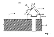
本発明の第1の実施形態が図1に示されている。図1は、好ましくは硬質材加工(hard machining)に用いられる、本発明に従った第1の工具100の模式的な断面図を示したものである。この工具100は、素材(ワークピース:work piece)のツースギャップ(tooth gap)を機械加工するために示されている。
工具100は、図1では模式的にのみ示されているカッターヘッド(cutter head)40を備えている。該カッターヘッド40は、工具100がその廻りに回転する工具軸線Aを備えている。カッターヘッド40は、その周囲に沿って幾つかのグループの工具を担持している。各工具グループは、この場合、2個の総形刃(フォームブレード:form blade)30を備えている。
図1は、かかる総形刃20の一つのみを示している。各総形刃20はベース本体部(ベースボディ:base body)21を備えており、該ベース本体部には、カーターヘッド40への取付のためのクランプ本体(クランプボディ:clamping body)21.1が、備えられ或いは設けられている。該クランプ本体21.1は、接線方向における様々の位置決めと、例えば、締め付けネジ部材により、或いは、図1に示されるように蟻継(dovetail)の固定システム22により、ベース本体部21をしっかりと固定(クランプ:clamp)することを許容している。
A first embodiment of the present invention is shown in FIG. FIG. 1 shows a schematic cross-sectional view of a
The
FIG. 1 shows only one such general blade 20. Each total shape blade 20 is provided with a base body portion (base body) 21, and the base body portion includes a clamp body (clamping body) 21.1 for attachment to the
前記カッターヘッド40は、軟質材加工および硬質材加工に対して、等しく役目を果たし得る。総形刃10又は20は、好ましくは、それぞれの加工形状に調整されている。軟質材加工においては、好ましくは、その切削エッジ(カッティングエッジ:cutting edge)を再研磨することができない硬質金属製のカッターバー13.1から13.3が、本発明に従って用いられる。総形刃を取り外し,再研磨し,蘇生して取り付けるのに今まで要していた時間は、本発明に従って、その発生を回避することができる。
The
立方晶窒化ホウ素(CBN:cubic crystal boron nitride)メッキしたカッターバー13.1から13.3は、本発明に従って、好ましくは硬質材加工に用いられる。それらは再研磨することができる。 Cubic crystal boron nitride (CBN) plated cutter bars 13.1 to 13.3 are preferably used for hard material processing according to the present invention. They can be reground.
更に、第1切削体(カッティングボディ:cutting body)に対して第1取付領域12.1が設けられている。第1切削体とは、ここでは第1カッターバーと指称されるカッターバー13.1である。 Furthermore, a first attachment region 12.1 is provided for the first cutting body (cutting body). Here, the first cutting body is a cutter bar 13.1, referred to herein as a first cutter bar.
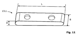
本特許出願では、用語カッターバーは、横長の平坦な切削体を表している。本発明に従ったカッターバー13.1は、典型的には、図11に示されるように、幅B及び厚さDよりも大きい長さLを有している。このことは、次の関係が成り立つことを意味している:
L>>B、且つ、L>>Dであり、しばしばB>D
カッターバー13.1は、その寸法が以下のグリッド(grid)に入っていることが特に好ましい:
L/Bの比が、1.5から5の間、好ましくは、1.7から4.7の間;
L/HGの比が、4から10の間、好ましくは、5から7の間。
更に、B/Hの比は、1.2から3の間、好ましくは、1.25から2.9の間、を取り得る。B/Hの比についてのこれら詳細は、随意(オプショナル:optional)である。カッターバー13.2の寸法は、カッターバー13.1の寸法とは異なっている。厚さD及び幅Bは、典型的には、カッターバー13.1の幅B及び厚さDと同じであるが、長さは僅かに短い。カッターバー13.2は、1.1から1.5の間のその長さLが、カッターバー13.1の長さよりも短いことが、特に好ましい。
In this patent application, the term cutter bar represents a horizontally long flat cutting body. A cutter bar 13.1 according to the present invention typically has a length L greater than a width B and a thickness D, as shown in FIG. This means that the following relationship holds:
L >> B and L >> D, often B> D
The cutter bar 13.1 is particularly preferably dimensioned in the following grid:
The ratio of L / B is between 1.5 and 5, preferably between 1.7 and 4.7;
The ratio of L / HG is between 4 and 10, preferably between 5 and 7.
Furthermore, the ratio of B / H can be between 1.2 and 3, preferably between 1.25 and 2.9. These details about the ratio of B / H are optional. The dimensions of the cutter bar 13.2 are different from the dimensions of the cutter bar 13.1. The thickness D and width B are typically the same as the width B and thickness D of the cutter bar 13.1, but the length is slightly shorter. It is particularly preferred that the cutter bar 13.2 has a length L between 1.1 and 1.5 shorter than the length of the cutter bar 13.1.
かかるカッターバー13.1,13.2は、全ての実施形態において用いられる。 Such cutter bars 13.1, 13.2 are used in all embodiments.
本発明に従ったカッターバー13.1は、好ましくは、平面視で長方形もしくは殆ど長方形の形状を有しており、各長方形は、図12Aから図12Dに示されるように、長さL及びBの縁部(エッジ:edge)によって規定されている。本発明に従ったカッターバー13.1は、また、斜方形の形状を有することもでき、この斜方形の側縁部は、図13Aから図13Bに示されるように、長さL及びBによって規定される。 The cutter bar 13.1 according to the invention preferably has a rectangular or almost rectangular shape in plan view, each rectangle having a length L and B, as shown in FIGS. 12A to 12D. Is defined by the edge. The cutter bar 13.1 according to the invention can also have a rhombic shape, the side edges of which are according to the lengths L and B, as shown in FIGS. 13A to 13B. It is prescribed.
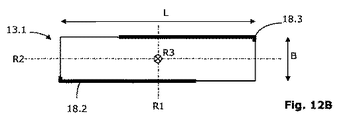
カッターバー13.1,13.2及び13.3は、それら各々が4つの切削エッジを有するように配置されているものであることが、特に好ましい。4つの切削エッジ18.1から18.4を備えた長方形状のカッターバー13.1が、図12Aから図12Dに示されている。このカッターバー13.1は、3本の軸R1,R2及びR3の廻りに回転させられることができる。他の切削エッジは、これらの軸廻りの回転によって使用される。
図12Aでは、切削エッジ18.1は、当該切削エッジ18.1が切削するように配列されている。カッターバー13.1が、ベース本体部11から取り外されて、軸R1の廻りに回転させられると、図12Bに示されるように、切削エッジ18.2が用いられる。
−切削エッジ18.2は、カッターバー13.1の後部側で、切削エッジ18.1の反対側に斜め方向に配置されている。カッターバー13.1が、ベース本体部11から取り外されて、軸R3の廻りに回転させられると、図12Cに示されるように、切削エッジ18.3が用いられる。切削エッジ18.3は、切削エッジ18.2と共に、カッターバー13.1の後部側に位置している。カッターバー13.1が、ベース本体部11から取り外されて、軸R2の廻りに回転させられると、図12Dに示されるように、切削エッジ18.4が用いられる。切削エッジ18.4は、切削エッジ18.1と共に、カッターバー13.1の前部側に位置している。
It is particularly preferred that the cutter bars 13.1, 13.2, and 13.3 are arranged so that each of them has four cutting edges. A rectangular cutter bar 13.1 with four cutting edges 18.1 to 18.4 is shown in FIGS. 12A to 12D. This cutter bar 13.1 can be rotated about three axes R1, R2 and R3. Other cutting edges are used by rotation around these axes.
In FIG. 12A, the cutting edges 18.1 are arranged such that the cutting edges 18.1 cut. When the cutter bar 13.1 is removed from the
The cutting edge 18.2 is arranged obliquely on the rear side of the cutter bar 13.1 on the opposite side of the cutting edge 18.1. When the cutter bar 13.1 is removed from the
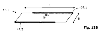
カッターバー13.1は、また、それら各々が2つの切削エッジを有するように構成されたものも、好適である。図13A及び図13Bは、2つの切削エッジ18.1及び18.2を備えた斜方形状のカッターバー13.1を示している。このカッターバー13.1は、軸R3の廻りに回転させられることができる。図13Aでは、切削エッジ18.1は、当該切削エッジ18.1が切削するように配列されている。カッターバー13.1が、ベース本体部11から取り外されて、軸R3の廻りに回転させられると、図13Bに示されるように、切削エッジ18.2が用いられる。切削エッジ18.2は、カッターバー13.1の同じ側(前部側)で、切削エッジ18.1の反対側に斜め方向に配置されている。
Cutter bars 13.1 are also suitable that are each configured to have two cutting edges. 13A and 13B show an obliquely shaped cutter bar 13.1 with two cutting edges 18.1 and 18.2. This cutter bar 13.1 can be rotated about the axis R3. In FIG. 13A, the cutting edges 18.1 are arranged so that the cutting edges 18.1 cut. When the cutter bar 13.1 is removed from the
2つ若しくはそれ以上の切削エッジを備えたかかるカッターバーは、全ての実施形態において用いられる。 Such a cutter bar with two or more cutting edges is used in all embodiments.
本発明に従った工具100は、更に、ベース本体部21上に第2取付領域12.2(例えば図4A参照)を備えている。該第2取付領域12.2は、第2カッターバー13.2を取り付けるために配置されている。
本発明によれば、第1取付領域12.1と第2取付領域12.2とは、ベース本体部21上で、空間的にずれる(オフセットする:offset)ように配置されている。この空間的なオフセットは、機械加工中に生成する切削屑(チップ:chip)の厚さとサイズを決定付ける。切削屑スペース(チップスペース:chip space)16のサイズは、それに応じて計画することができる(かかるチップスペース16は、例えば、図7B或いは図10に示されている)。
The
According to the present invention, the first attachment region 12.1 and the second attachment region 12.2 are arranged on the
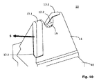
空間的なオフセットは、切削方向S(例えば図7B参照)において見たとき、第1カッターバー13.1が、ベース本体部11上で第2カッターバー13.2の前にあることを意味している。第1カッターバー13.1は、好ましくは、第2カッターバー13.2よりも長く(Lがより長い)、第1カッターバー13.1が主切刃(main cutting blade)18.1を与える一方、第2カッターバー13.2は第二次的な切刃(secondary cutting blade)18.5を与える(例えば図7E参照)。
The spatial offset means that the first cutter bar 13.1 is in front of the second cutter bar 13.2 on the
本特許出願では、用語ベース本体部11,21は、カッターバー13.1から13.4に対する支持体を規定するために用いられるべきものである。好ましくは、ベース本体部11,21は、錐体状(ピラミッド状:pyramidal)或いは先細の形状を有している。かかるベース本体部11,21は、全ての実施形態において用いられる。
In the present patent application, the term
本発明の第2の実施形態が図2に示されている。
図2は、好ましくは軟質材加工(soft machining)に用いられる、本発明に従った第2の工具100の模式的な断面図を示したものである。この工具100は、未だ硬化処理されていないワークピースのツースギャップを機械加工するために示されている。工具100は、図2では模式的にのみ示されているカッターヘッド40を備えている。該カッターヘッド40は、工具100がその廻りに回転する工具軸線Aを備えている。カッターヘッド40は、その周囲に沿って幾つかのグループの工具を備えている。各工具グループは、この場合、2個の総形刃10を備えている。
図1は、かかる総形刃10の一つのみを示している。各総形刃10はベース本体部11を備えており、該ベース本体部には、カーターヘッド40への挿入のための結合領域11.1が設けられている。該結合領域11.1は、好ましくは、ベース本体部11の一体的な要素である。結合領域11.1は、ねじ込むことができ、溶接することもでき、或いは、他の如何なる方法でもベース本体部11に固定することができる。
A second embodiment of the invention is shown in FIG.
FIG. 2 shows a schematic cross-sectional view of a
FIG. 1 shows only one such
更に、第1切削体に対して第1取付領域12.1が設けられている。第1切削体とは、ここでは第1カッターバーと指称されるカッターバー13.1である。本発明に従った工具100は、更に、ベース本体部11上に第2取付領域12.2(例えば図7D参照)を備えている。該第2取付領域12.2は、第2カッターバー13.2を取り付けるために配置されている。本発明によれば、第1取付領域12.1と第2取付領域12.2とは、ベース本体部11上で、お互いに関して空間的にオフセットするように(in a spatially offset manner)配置されている。
Furthermore, a first attachment region 12.1 is provided for the first cutting body. Here, the first cutting body is a cutter bar 13.1, referred to herein as a first cutter bar. The
切削屑スペース(チップスペース)16として用いられる空洞部がベース本体部11,21に設けられている実施形態が、特に好ましい。このような特に好ましい実施形態の詳細が、図10に示されている。かかるチップスペース16は全ての実施形態において設けることができ、金属の切り屑が、工具100の過熱を何ら伴うことなく、容易に除去できるという利点をもたらす。この空洞部は、内側に面する凹所,窪み或いは切欠部を形成するように選定される。
An embodiment in which a hollow portion used as the cutting waste space (chip space) 16 is provided in the
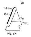
カッターバー13.1を備えた総形刃10が、図3Aから図3Cに示されている。
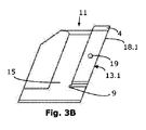
図3Aは総形刃10の正面図を、図3Bは総形刃10の左方からの側面図を、また、図3Cは総形刃10の全体図を、それぞれ示している。総形刃10は、図示された実施形態においてはカッターバー13.1を受容するように構成されたベース本体部11(プレートホルダ1)を備えている。ベース本体部11及びカッターバー2は、従来の総形刃に代わるものとして一緒に用いられ、従って、ここでは、やはり総形刃10と指称される。
この総形刃10には、2つの刃先(切削エッジ)が設けられている。それらは、主カッターと、通常はヘッドカッター(head cutter)と呼ばれる第二次的なカッターである。図13Aにおいては、これらのカッターは、参照符号18.1で明示され、太線で模式的に示されている。
A
3A is a front view of the
The
このカッターバー13.1は、ベース本体部11の浮き彫り(レリーフ:relief)面15の領域に配置されている、すなわち、ベース本体部11の側部に張り出している。
The cutter bar 13.1 is arranged in the region of the
カッターバー13.1は、硬質金属(ハードメタル)で製作され、長手方向側部に沿ってヘッド領域4まで延びるグラウンド(ground)刃先(グラウンド切削エッジ)を備えている。切削エッジ13.1は、好ましくは、大モジュールの傘歯車の端部加工(エンドマシーニング:end machining)のためのグラウンドイン突起部(ground-in protuberance)を備えている。切削エッジ18.1のエッジ長さは、様々のサイズのモジュールに好適であり、このことは、カッターバー13.1が、異なるモジュールの傘歯車のギヤ加工に使用し得ることを意味している。
The cutter bar 13.1 is made of hard metal and has a ground cutting edge that extends to the
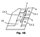
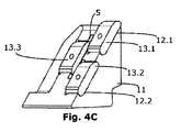
本発明に従った第1の実施形態が図4Aから図4Cに示されている。図4Aは新規な総形刃10の正面図を、図4Bは前記総形刃10の左方からの側面図を、また、図4Cは前記総形刃10の全体図を、それぞれ示している。総形刃10は、図示された例においては3つのカッターバー13.1,13.2及び13.3を受容するように設計されたベース本体部11を備えている。
A first embodiment according to the present invention is shown in FIGS. 4A to 4C. 4A is a front view of the new
カッターバー13.1,13.2及び13.3の特別な種類の配置の結果、傘歯車のツースギャップのフライス加工中、所謂カッティング・ディビジョン(cutting division)が生じる。このカッティング・ディビジョンは、例えば、カッターバー13.1の一つが主カッター18.1を与える一方、第2のカッターバー13.2が第二次的なカッター18.5を与えるようにして得られる。 As a result of the special kind of arrangement of the cutter bars 13.1, 13.2 and 13.3, a so-called cutting division occurs during milling of the tooth gap of the bevel gear. This cutting division is obtained, for example, such that one of the cutter bars 13.1 gives the main cutter 18.1, while the second cutter bar 13.2 gives the secondary cutter 18.5. .
この実施形態は、大モジュールの傘歯車に対する荒加工に特に好適である。 This embodiment is particularly suitable for roughing a large module bevel gear.
焼結構造の硬質金属製カッターバー13.1,13.2及び13.3は、廉価であるので、本実施形態においては特に好ましい。 Sintered hard metal cutter bars 13.1, 13.2, and 13.3 are particularly preferred in this embodiment because they are inexpensive.
カッターバー13.1,13.2及び13.3は、好ましくは、それら各々が、図12Aから図12Dに関連して説明されるように、4つの切削エッジを備えるように設計されている。後部のカッティングバー13.3は、異なるピッチ円半径を橋渡しするために、接線方向の調整可能性を有していなければならない。各々のピッチ円半径は、カッターヘッド40の軸線に関するカッターバー13.1,13.2及び13.3の距離から得られる。接線方向の調整可能性は、図示された実施形態では、図4B及び図4Cに示されように、ベース本体部11に長手方向の溝部5が設けられるようにして、達成される。
The cutter bars 13.1, 13.2, and 13.3 are preferably designed so that each of them has four cutting edges, as described in connection with FIGS. 12A-12D. The rear cutting bar 13.3 must have tangential adjustability to bridge different pitch circle radii. Each pitch circle radius is obtained from the distance of the cutter bars 13.1, 13.2, and 13.3 with respect to the axis of the
更なる総形刃10が図5Aから図5Cに示されている。
図5Aは前記総形刃10の正面図を、図5Bは前記総形刃10の左方からの側面図を、また、図5Cは前記総形刃10の全体図を、それぞれ示している。総形刃10は、図示された例においてはカッターバー13.1を受容するように構成されたベース本体部11を備えている。図3Aから図3C及び図4Aから図4Cに示された総形刃10とは対照的に、ここでは、カッターバー13.1の下側の領域に配置された偏向要素(エキセントリック・エレメント:eccentric element)6が用いられている。
A
5A is a front view of the
図5Bに示されるように、偏向要素6はネジ部6.1を備えることができる。偏向アーム6.2(図5A参照)は、ネジ6.1を回すことによって動かされる。前記偏向アーム6.2は、カッターバー13.1の底端部と相互作用しており、図5Cにおいて往復矢印Hで示されるように、カッターバー13.1の底端部の高さ位置を変位させることができる。
As shown in FIG. 5B, the
この総形刃10は、偏向要素6を介して高さ調節が可能であることにより容易な調節機能が付与されているので、荒加工および仕上げ加工に特に好適である。偏向要素6は、全ての他の実施形態においても同様に使用することができる。個々の高さ調節機能のために、カッターバー13.1,13.2,13.3の一つが幾つかの偏向要素6を備えているか、或いは、全てのカッターバー13.1,13.2,13.3が一つの偏向要素6を備えている。
The
更なる実施形態が図6Aから図6Cに示されている。
図6Aは新規な総形刃10の正面図を、図6Bは前記総形刃10の左方からの側面図を、また、図6Cは前記総形刃10の全体図を、それぞれ示している。総形刃10は、図示された例においてはカッターバー13.1を受容するように構成されたベース本体部11を備えている。他の実施形態とは対照的に、ここでは、カッターバー13.1の下側の領域に配置された支持板17が用いられている。この支持板17には、前記偏向要素6よりも堅固であるという利点がある。
A further embodiment is shown in FIGS. 6A to 6C.
6A is a front view of the new
この総形刃10も、支持板17を介して高さ調節が可能であることにより容易な調節機能が付与されているので、荒加工および仕上げ加工に特に好適である。支持板17は、全ての他の実施形態においても同様に使用することができる。
The
支持板17は、単なる支持作用に加えて、切削エッジを備えることもできる。支持板17が切削エッジを備えている場合には、図6Aから図6Cに示された実施形態においても、カッターバー13.1と支持板17との間でカッティング・ディビジョンが在る。
The
本発明の実施形態は、(複数の)カッターバー13.1,13.2,13.3がベース本体部11に接線方向にクランプされているものが、特に好ましい(この場合、「接線方向に」は切削速度の方向に略対応している;換言すれば、「接線方向」は、ここでは、工具の直径またはカッターヘッドの直径の接線に対応している)。この接線方向にクランプすることは、切削中(複数の)カッターバー13.1,13.2,13.3がそれぞれの取付領域12.1,12.2,12.3に押し付けられているので、非常に堅固である。 In the embodiment of the present invention, it is particularly preferable that the cutter bars 13.1, 13.2, 13.3 are clamped in the tangential direction to the base body 11 (in this case, “in the tangential direction”). "Roughly corresponds to the direction of the cutting speed; in other words" tangential direction "here corresponds to the tangent of the diameter of the tool or the diameter of the cutter head). Clamping in this tangential direction is because the cutting bar (s) 13.1, 13.2, 13.3 are pressed against the respective attachment areas 12.1, 12.2, 12.3 during cutting. Is very solid.
しかも、ベース本体部11の自由表面(free surface)3上にクランプすることは、それぞれの取付領域12.1,12.2,12.3における(複数の)カッターバー13.1,13.2,13.3の広い接触面をもたらす。この広い接触面の結果として、傘歯車のフライス加工中に発生する力は、ベース本体部11内によりうまく導かれて分散される。
Moreover, clamping onto the
(複数の)カッターバー13.1,13.2,13.3は、好ましくは、ネジでベース本体部11に結合されている。図3B及び図3Cは、参照数字符号19を伴った各ネジ穴を示している。図4B,4C,5B,5C,6B,6C,7B,7C,7D,7E及び11は、類似した穴部を示している。それらは、図の明瞭化のために、参照数字符号を伴った表示はされていない。
The cutter bar (s) 13.1, 13.2, 13.3 are preferably coupled to the
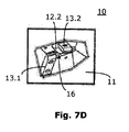
図7Aから図7Eは、特に軟質材加工用に構成された特に好ましい実施形態を示している。
カッターヘッド40に挿入されるべき全ての総形刃10は、カッターヘッド40内への挿入用の結合領域11.1を有するベース本体部11を備えている(図2も参照)。第1切削体として用いられる第1カッターバー13.1がベース本体部11に結合されている。ベース本体部11の第2取付領域12.2は、第2カッターバー13.2を受容して結合させるために用いられる。
チップスペース16として用いられる空洞部が、好ましくは2つのカッターバー13.1,13.2の間に設けられている。図示された実施形態では、チップスペース16として用いられる空洞部は、2つのカッターバー13.1,13.2が、その上端がベース本体部11の領域を僅かに越えて突き出るようにして得られる。このようにして、チップスペース16として用いられる中間の空間部が、突出したカッターバー13.1,13.2の間に得られる。前記チップスペース16は、また、ベース本体部に(つまり、ベース本体部11の素材に)凹所が設けられるようにして形成される(或いは、追加して形成される)こともできる(例えば、図10参照)。
Figures 7A to 7E show a particularly preferred embodiment configured especially for soft material processing.
All the
A cavity used as the
カッターバー13.1,13.2,13.3用の取付領域は、第1カッターバー13.1及び第2カッターバー13.2が空間的にオフセットするようにして配置され、チップスペース16が第1カッターバー13.1と第2カッターバー13.2との間の領域に設けられるようにして、ベース本体部11上に配設される。
The mounting area for the cutter bars 13.1, 13.2, 13.3 is arranged such that the first cutter bar 13.1 and the second cutter bar 13.2 are spatially offset, and the
図7Eには、軸R1,R2及びR3が示されている。カッターバー13.1は、他の切削エッジ18.1,18.2,18.3若しくは18.4の各々を使用するために、前記3つの軸廻りに回転または絡まされることができる。切削エッジ18.3は、反対側に在るので、図7Eには表示されていない。切削エッジ18.1,18.2及び18.4は、太い黒線で概略的に表示されている。軸R1は、切削方向Sと略一致している。 In FIG. 7E, axes R1, R2 and R3 are shown. The cutter bar 13.1 can be rotated or entangled about the three axes in order to use each of the other cutting edges 18.1, 18.2, 18.3 or 18.4. The cutting edge 18.3 is not shown in FIG. 7E because it is on the opposite side. The cutting edges 18.1, 18.2, and 18.4 are schematically indicated by thick black lines. The axis R1 substantially coincides with the cutting direction S.
図8A及び図8Bは、7つの総形刃10のグループを収容することができる第1のカッターヘッド40を示している。この場合、各グループは、2つの総形刃10を備えている。半径方向に指向させられた14のガイド溝41がカッターヘッド40上に設けられ、これらガイド溝は外側の円筒面42に開口している。ベース本体部11又は21の結合領域11.1又は21.1は、外側の円筒面42からガイド溝41内へ挿入することができる。ベース本体部11,21は、半径方向に指向したガイド溝41内において、個々にそして連続的に、半径方向に位置して固定することができる。
8A and 8B show a
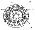
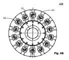
図9A及び図9Bは、図8A及び図8Bに係るカッターヘッド40を、当該カッターヘッドが総形刃10を完全に装備した状態で示している。7つのグループの各々は、(創成されるべき歯間の内側および外側のフランク面のための)内側カッターと外側カッターとを備えている。図7は、内側カッターとして使用される各総形刃10を示している。
FIGS. 9A and 9B show the
図面は、更に、カッターバー13.1,13.2,13.3の底部端末に、例えば丸穴9の形態で凹所を備えることができる(図3B,3C,4B,4C,5B,5C,6B,6C,7B,7C,7E参照)。この凹所は、各カッターバー13.1,13.2,13.3の各尖ったエッジ部を受容するのに用いられる。この方法の結果、ベース本体部11の取付領域12.1,12.2,12.3の精度は、より低くて済む。各凹所の適用は随意的なものである。
The drawing can further be provided with a recess in the bottom end of the cutter bar 13.1, 13.2, 13.3, for example in the form of a round hole 9 (FIGS. 3B, 3C, 4B, 4C, 5B, 5C). , 6B, 6C, 7B, 7C, 7E). This recess is used to receive each sharp edge of each cutter bar 13.1, 13.2, 13.3. As a result of this method, the accuracy of the attachment regions 12.1, 12.2, and 12.3 of the base
更なる随意的な特徴が、図3C,4C及び6Cに示されている。カッターバー13.1,13.2,13.3の底部端末に、カッターバー13.1,13.2,13.3及び/又は支持板17が、窪み又は背面側に向かってオフセットした背面側を備えていてもよい。これらの随意的な方法は、ベース本体部11上へのカッターバー13.1,13.2,13.3のより良好な着座を確かなものとする。背面側が窪んでいたり背面側に向かってオフセットしていれば、各カッターバーは、もはや他の切削エッジの使用のために回転したり向きを変えたりすることはできない。
A further optional feature is shown in FIGS. 3C, 4C and 6C. The back side where the cutter bars 13.1, 13.2, 13.3 and / or the
カッターバー13.1,13.2,13.3の研磨の品質および幾何学的な精度は、傘歯車のワークピースの製作品質を達成するために非常に重要である。 The polishing quality and geometric accuracy of the cutter bars 13.1, 13.2, 13.3 are very important to achieve the fabrication quality of the bevel gear workpiece.
本発明に従ったカッターバー13.1,13.2,13.3は、既に述べたように、硬質金属で製作されている。カッターバー13.1,13.2,13.3は、特に、少なくとも部分的に被覆加工されていることが好ましい。 The cutter bars 13.1, 13.2, 13.3 according to the invention are made of hard metal, as already mentioned. The cutter bars 13.1, 13.2, 13.3 are particularly preferably at least partially coated.
本発明に従ったカッターバー13.1,13.2,13.3は、高速度鋼(HSS)で製作することもできる。 The cutter bars 13.1, 13.2, 13.3 according to the invention can also be made of high speed steel (HSS).
本発明の工具10は、軟質材加工あるいは大モジュールの傘歯車に、特に好適である。
−また、この工具は、典型的には小さいモジュールの傘歯車が使用されるのであるが、例えば自動車産業での使用にも好適である。
The
The tool is also suitable for use in the automotive industry, for example, although typically small module bevel gears are used.
本発明に従った工具10は、ジクロ・パロイド(Zyklo-Palloid)螺旋状傘歯車を機械加工するのに、特に好適である。
The
本発明の工具10は、傘歯車の乾式機械加工用に設計することもできる。
The
前記カッターバー13.1,13.2,13.3は、好ましくは、本発明に従った硬質金属で製作され、メインの切刃からヘッドの切刃に収束する、少なくとも1つのグランド・切削エッジ18.1を備えている。 Said cutter bar 13.1, 13.2, 13.3 is preferably made of hard metal according to the invention and has at least one ground cutting edge that converges from the main cutting edge to the cutting edge of the head 18.1.
焼結された形態の硬質金属製のカッターバー13.1,13.2,13.3は、軟質材加工に特に好ましい。 Sintered hard metal cutter bars 13.1, 13.2, 13.3 are particularly preferred for soft material processing.
ベース本体部11及び12は、好ましくは、本発明に従った表面硬化で硬化された鋼で製作される。
The
図に示され説明されたカッターヘッド40は、柔軟性をもって各総形刃10を装備することができ、また、1つの同じカッターヘッド40を、種々の調整および設定の結果、異なるモジュール範囲に対して使用し得る点で、特徴付けられる。非常に柔軟に使用することのできる標準的な工具システムが提供される。
The
本発明は、ベース本体部とカッターバーの形態に応じて、歯車の軟質材加工と硬質材加工とに用いることができる、新しい工具システムを提供するものである。工具100でもって生産性を顕著に高めることができる。しかも、他の対比できる解決法と比較して、コストをかなり低減することができる。
The present invention provides a new tool system that can be used for soft material processing and hard material processing of gears according to the form of the base body and the cutter bar. With the
10 軟質材加工用の工具(総形刃)
11 軟質材加工用のベース本体部
11.1 結合領域
12.1 第1取付領域
12.2 第2取付領域
13.1 第1カッターバー
13.2 第2カッターバー
13.3 第3カッターバー
15 自由表面
16 切削屑スペース
17 結合手段(支持板)
18.1,18.2,18.3,18.4,18.5 切削エッジ
19 ネジ部材
20 硬質材加工用の工具
21 硬質材加工用のベース本体部
21.1 硬質材加工用のクランプ本体(結合領域)
22 蟻継クランプシステム
40 カッターヘッド
41 半径方向に指向したガイド溝
42 円筒外周面
43 工具スピンドル受け
100 工具
A 工具スピンドル軸
B 幅
D 厚さ
L 長さ
S 切削方向
R1 軸
R2 軸
R3 軸
10 Tools for machining soft materials (general blade)
11. Base body for processing soft material 11.1 Bonding area 12.1 First mounting area 12.2 Second mounting area 13.1 First cutter bar 13.2 Second cutter bar 13.3
18.1, 18.2, 18.3, 18.4, 18.5
22
Claims (13)
−第1切削体としての役割を果たす第1カッターバー(13.1)と、
−第2カッターバー(13.2)のための、前記ベース本体部(11;21)上の第2取付領域(12.2)と、
−第2カッターバー(13.2)と、
−切削屑スペース(16)としての役割を果たすキャビティ部と、を備え、
第1カッターバー(13.1)と第2カッターバー(13.2)とが互いに空間的にオフセットし、前記切削屑スペース(16)が第1カッターバー(13.1)と第2カッターバー(13.2)の間の領域に配置されるように、前記第1取付領域(12.1)と第2取付領域(12.2)とが前記ベース本体部(11;21)上に位置決めされている、
ことを特徴とする工具(100)。 A cutter head (40) and several groups of tools, each group of tools having a first attachment area (12.1) for a first cutting body and insertion in the cutter head (40). A tool (100) having a base body part (11; 21) comprising a coupling region (11.1) for and a first cutting body,
A first cutter bar (13.1) serving as a first cutting body;
A second mounting area (12.2) on the base body (11; 21) for the second cutter bar (13.2);
-A second cutter bar (13.2);
-A cavity part serving as a cutting waste space (16),
The first cutter bar (13.1) and the second cutter bar (13.2) are spatially offset from each other, and the cutting waste space (16) is the first cutter bar (13.1) and the second cutter bar. The first mounting region (12.1) and the second mounting region (12.2) are positioned on the base body (11; 21) so as to be disposed in a region between (13.2). Being
A tool (100) characterized in that.
前記カッターバー(13.1,13.2,13.3)は、高速度鋼(HSS)で成り、好ましくは、CBNコーティングされている、ことを特徴とする工具(100)の使用。 Use of the tool (100) according to any one of claims 1 to 9 for hard material processing of a gear material, preferably a bevel gear material, after the curing step,
Use of a tool (100) characterized in that the cutter bar (13.1, 13.2, 13.3) is made of high speed steel (HSS), preferably CBN coated.
Applications Claiming Priority (2)
| Application Number | Priority Date | Filing Date | Title |
|---|---|---|---|
| DE202007007063U DE202007007063U1 (en) | 2007-05-16 | 2007-05-16 | Bevel gear milling tool with milling cutting plates |
| PCT/EP2008/054926 WO2008138718A1 (en) | 2007-05-16 | 2008-04-23 | Cutting tool for bevel gears with cutting strips |
Related Child Applications (1)
| Application Number | Title | Priority Date | Filing Date |
|---|---|---|---|
| JP2013132981A Division JP5746734B2 (en) | 2007-05-16 | 2013-06-25 | Umbrella gear cutting tool with cutter bar and method of using the same |
Publications (2)
| Publication Number | Publication Date |
|---|---|
| JP2010526679A true JP2010526679A (en) | 2010-08-05 |
| JP2010526679A5 JP2010526679A5 (en) | 2013-02-28 |
Family
ID=38542743
Family Applications (2)
| Application Number | Title | Priority Date | Filing Date |
|---|---|---|---|
| JP2010507868A Pending JP2010526679A (en) | 2007-05-16 | 2008-04-23 | Bevel gear cutting tool with cutter bar |
| JP2013132981A Expired - Fee Related JP5746734B2 (en) | 2007-05-16 | 2013-06-25 | Umbrella gear cutting tool with cutter bar and method of using the same |
Family Applications After (1)
| Application Number | Title | Priority Date | Filing Date |
|---|---|---|---|
| JP2013132981A Expired - Fee Related JP5746734B2 (en) | 2007-05-16 | 2013-06-25 | Umbrella gear cutting tool with cutter bar and method of using the same |
Country Status (7)
| Country | Link |
|---|---|
| US (1) | US8454275B2 (en) |
| EP (1) | EP2146814A1 (en) |
| JP (2) | JP2010526679A (en) |
| KR (1) | KR20100029206A (en) |
| CN (1) | CN101687261B (en) |
| DE (1) | DE202007007063U1 (en) |
| WO (1) | WO2008138718A1 (en) |
Cited By (1)
| Publication number | Priority date | Publication date | Assignee | Title |
|---|---|---|---|---|
| KR20150088289A (en) * | 2012-11-26 | 2015-07-31 | 발터 악티엔게젤샤프트 | Bell-shaped cutter |
Families Citing this family (14)
| Publication number | Priority date | Publication date | Assignee | Title |
|---|---|---|---|---|
| DE102007013153B4 (en) * | 2007-03-20 | 2019-01-24 | Kennametal Inc. | Tool |
| DE202007007063U1 (en) | 2007-05-16 | 2007-09-27 | Klingelnberg Ag | Bevel gear milling tool with milling cutting plates |
| DE102008063858A1 (en) * | 2008-12-19 | 2010-07-01 | Gebr. Heller Maschinenfabrik Gmbh | Machine tool and method for producing gears |
| DE102009008122B4 (en) * | 2009-02-09 | 2012-04-05 | Deckel Maho Pfronten Gmbh | Machine tool for machining a workpiece by machining and method for producing a toothed workpiece by hobbing |
| DE102011050451A1 (en) * | 2011-05-18 | 2012-11-22 | Renate Richardt | Bar blade head has connection region that is provided in lower position in relation to level of front end of outer edge of cutting head main portion to couple main portion to adapter |
| CN103252538B (en) * | 2012-02-16 | 2020-01-17 | 山特维克知识产权股份有限公司 | Face hobbing cutter system and indexable milling insert therefor |
| MX357653B (en) * | 2012-11-09 | 2018-07-18 | The Gleason Works | Gear cutter with radial adjustability of stick blades. |
| EP2810729A1 (en) | 2013-06-05 | 2014-12-10 | Boehlerit GmbH & Co. KG. | Tool with cutting plates, adapter with cutting plates and use of such a tool |
| SE1350983A1 (en) * | 2013-08-27 | 2015-02-28 | Sandvik Intellectual Property | Tools and cutters for shell milling |
| EP2871015B1 (en) * | 2013-11-11 | 2018-10-10 | Sandvik Intellectual Property AB | Gear milling cutter as well as an insert holder and a chip removal unit |
| US20160332240A1 (en) | 2015-05-15 | 2016-11-17 | Arvinmeritor Technology, Llc | Cutting tool assembly and method of manufacture |
| DE102016101145B4 (en) * | 2016-01-22 | 2019-06-27 | Hartmetall-Werkzeugfabrik Paul Horn Gmbh | milling tool |
| US10384270B1 (en) * | 2018-03-08 | 2019-08-20 | Honda Motor Co., Ltd. | Cutting tool |
| US11117203B2 (en) * | 2018-12-20 | 2021-09-14 | Kennametal Inc. | Cutting insert holder and applications thereof |
Citations (6)
| Publication number | Priority date | Publication date | Assignee | Title |
|---|---|---|---|---|
| JPS57102722A (en) * | 1980-10-16 | 1982-06-25 | Fette Wilhelm Gmbh | Cylindrical edge tool with edge plate |
| JPS62817Y2 (en) * | 1981-12-24 | 1987-01-09 | ||
| JPS62166920A (en) * | 1986-01-21 | 1987-07-23 | Nissho Seiko Kk | Throwaway type gear hob |
| JPH0160825U (en) * | 1987-10-14 | 1989-04-18 | ||
| JPH1058219A (en) * | 1991-04-11 | 1998-03-03 | Gleason Corp | Rotary ring cutter |
| JP2005177938A (en) * | 2003-12-19 | 2005-07-07 | Mitsubishi Fuso Truck & Bus Corp | Bevel gear cutter |
Family Cites Families (18)
| Publication number | Priority date | Publication date | Assignee | Title |
|---|---|---|---|---|
| US1495067A (en) * | 1922-12-22 | 1924-05-20 | O K Tool Co | Hob having side-tooth inserts |
| US1667299A (en) * | 1927-03-16 | 1928-04-24 | Gleason Works | Gear cutter |
| GB485279A (en) * | 1937-01-15 | 1938-05-17 | Gleason Works | Improvements in gear cutting tools |
| US2932239A (en) * | 1956-06-04 | 1960-04-12 | Wildhaber Ernest | Face hob and method of hobbing straight-tooth bevel gears |
| US2974399A (en) * | 1958-03-27 | 1961-03-14 | Gleason Works | Cutter for gears of tapering tooth depth |
| CH512957A (en) * | 1970-09-09 | 1971-09-30 | Wahli Freres Sa | Process for milling, chamfering and deburring straight or helical toothed wheels using hobs |
| DD109817A1 (en) * | 1974-02-18 | 1974-11-20 | ||
| DE2515937B1 (en) * | 1975-04-11 | 1976-10-21 | Ingersoll Mach & Tool Co | Annular milling tool cutting plate - segments with flange parallel to rotation plane, crossways support |
| US4218159A (en) * | 1977-01-07 | 1980-08-19 | Sack Gmbh | Multiple-part hobbing cutter |
| US4565474A (en) | 1980-11-01 | 1986-01-21 | The Ingersoll Milling Machine Company | Method of generating involute tooth forms with a milling cutter |
| DE3241696C1 (en) * | 1982-11-11 | 1984-06-07 | Wälztechnik Saacke-Zorn GmbH & Co KG, 7530 Pforzheim | High performance hob cutter |
| CH660320A5 (en) * | 1983-02-18 | 1987-04-15 | Maag Zahnraeder & Maschinen Ag | TOOLING TOOLS. |
| GB8925360D0 (en) * | 1989-11-09 | 1989-12-28 | Sandvik Ltd | Milling cutters |
| SE501915C2 (en) * | 1993-03-18 | 1995-06-19 | Sandvik Ab | Fine cutter with recesses for axially adjustable cassettes |
| DE20016673U1 (en) * | 2000-09-27 | 2000-12-14 | Ingersoll Werkzeuge GmbH, 57299 Burbach | Tooth form cutter |
| MXPA04010231A (en) | 2002-04-18 | 2005-07-26 | Kennametal Inc | Gear hobbing cutter system. |
| EP1592529B2 (en) * | 2003-05-22 | 2011-03-09 | Klingelnberg GmbH | Bar blade for milling spiral bevel gears and hypoid gears |
| DE202007007063U1 (en) | 2007-05-16 | 2007-09-27 | Klingelnberg Ag | Bevel gear milling tool with milling cutting plates |
-
2007
- 2007-05-16 DE DE202007007063U patent/DE202007007063U1/en not_active Expired - Lifetime
-
2008
- 2008-04-23 EP EP08736500A patent/EP2146814A1/en not_active Withdrawn
- 2008-04-23 US US12/599,528 patent/US8454275B2/en active Active
- 2008-04-23 CN CN200880023819.2A patent/CN101687261B/en not_active Expired - Fee Related
- 2008-04-23 KR KR1020097026183A patent/KR20100029206A/en not_active Application Discontinuation
- 2008-04-23 WO PCT/EP2008/054926 patent/WO2008138718A1/en active Application Filing
- 2008-04-23 JP JP2010507868A patent/JP2010526679A/en active Pending
-
2013
- 2013-06-25 JP JP2013132981A patent/JP5746734B2/en not_active Expired - Fee Related
Patent Citations (6)
| Publication number | Priority date | Publication date | Assignee | Title |
|---|---|---|---|---|
| JPS57102722A (en) * | 1980-10-16 | 1982-06-25 | Fette Wilhelm Gmbh | Cylindrical edge tool with edge plate |
| JPS62817Y2 (en) * | 1981-12-24 | 1987-01-09 | ||
| JPS62166920A (en) * | 1986-01-21 | 1987-07-23 | Nissho Seiko Kk | Throwaway type gear hob |
| JPH0160825U (en) * | 1987-10-14 | 1989-04-18 | ||
| JPH1058219A (en) * | 1991-04-11 | 1998-03-03 | Gleason Corp | Rotary ring cutter |
| JP2005177938A (en) * | 2003-12-19 | 2005-07-07 | Mitsubishi Fuso Truck & Bus Corp | Bevel gear cutter |
Cited By (4)
| Publication number | Priority date | Publication date | Assignee | Title |
|---|---|---|---|---|
| KR20150088289A (en) * | 2012-11-26 | 2015-07-31 | 발터 악티엔게젤샤프트 | Bell-shaped cutter |
| JP2015535492A (en) * | 2012-11-26 | 2015-12-14 | バルター アクチェンゲゼルシャフト | Bell-shaped cutter |
| US9776256B2 (en) | 2012-11-26 | 2017-10-03 | Walter Ag | Bell-shaped cutter |
| KR102113894B1 (en) * | 2012-11-26 | 2020-05-22 | 발터 악티엔게젤샤프트 | Bell-shaped cutter |
Also Published As
| Publication number | Publication date |
|---|---|
| US20100196107A1 (en) | 2010-08-05 |
| DE202007007063U1 (en) | 2007-09-27 |
| KR20100029206A (en) | 2010-03-16 |
| WO2008138718A1 (en) | 2008-11-20 |
| CN101687261B (en) | 2015-06-03 |
| JP5746734B2 (en) | 2015-07-08 |
| US8454275B2 (en) | 2013-06-04 |
| EP2146814A1 (en) | 2010-01-27 |
| JP2013223920A (en) | 2013-10-31 |
| CN101687261A (en) | 2010-03-31 |
Similar Documents
| Publication | Publication Date | Title |
|---|---|---|
| JP5746734B2 (en) | Umbrella gear cutting tool with cutter bar and method of using the same | |
| RU2114721C1 (en) | Cutting tip | |
| CA2249960C (en) | Milling cutter | |
| US5704736A (en) | Dove-tail end mill having replaceable cutter inserts | |
| JP5641204B2 (en) | Christmas cutter and turbine blade root cutting method using the same | |
| JP4420827B2 (en) | Disc or strip tool | |
| JP7061371B2 (en) | Machine parts and their applications in cutting | |
| JP7481358B2 (en) | Milling cutter and its cutting edge | |
| KR20160050035A (en) | Peripheral cutting tool utilizing stick blades | |
| JP2019503877A (en) | Single blade bevel gear cutting tool | |
| US6540446B2 (en) | Cylindrical cutting blade and cutter head assembly which carries the cutting blade | |
| EP2186584A1 (en) | Cutting tool, method of forming cutting tool, and method of manufacturing cutting tool | |
| US20080118313A1 (en) | Milling insert and a milling insert tool for chip removing machining | |
| US3740808A (en) | Cutter particularly for gear hobbing | |
| JP2002301603A (en) | Throwaway cutting tip and method of positioning cutting tip holder and throwaway cutting tip | |
| WO2016165577A1 (en) | Manufacturing method for cutting tool | |
| KR20220051265A (en) | Method and device for deburring workpieces with internal teeth | |
| JPH11254222A (en) | Cutting tool | |
| JP2018103355A (en) | Cutting tool for thread whirling processing and cutting insert | |
| JP4940864B2 (en) | Throw-away rotary tool and tip mounted on it | |
| RU2424878C2 (en) | Cutting tool and milling head | |
| JP6609925B2 (en) | Hob | |
| JP7004250B2 (en) | Rotary cutting tools and chip dividers | |
| JP2007253307A (en) | Milling cutter and insert | |
| JP3029653U (en) | Spare blade type cutting tool |
Legal Events
| Date | Code | Title | Description |
|---|---|---|---|
| A621 | Written request for application examination |
Free format text: JAPANESE INTERMEDIATE CODE: A621 Effective date: 20100914 |
|
| A977 | Report on retrieval |
Free format text: JAPANESE INTERMEDIATE CODE: A971007 Effective date: 20120827 |
|
| A131 | Notification of reasons for refusal |
Free format text: JAPANESE INTERMEDIATE CODE: A131 Effective date: 20120904 |
|
| A601 | Written request for extension of time |
Free format text: JAPANESE INTERMEDIATE CODE: A601 Effective date: 20121203 |
|
| A602 | Written permission of extension of time |
Free format text: JAPANESE INTERMEDIATE CODE: A602 Effective date: 20121210 |
|
| A524 | Written submission of copy of amendment under article 19 pct |
Free format text: JAPANESE INTERMEDIATE CODE: A524 Effective date: 20130104 |
|
| A02 | Decision of refusal |
Free format text: JAPANESE INTERMEDIATE CODE: A02 Effective date: 20130226 |
