JP2010525974A - Fire barrier - Google Patents
Fire barrier Download PDFInfo
- Publication number
- JP2010525974A JP2010525974A JP2010504565A JP2010504565A JP2010525974A JP 2010525974 A JP2010525974 A JP 2010525974A JP 2010504565 A JP2010504565 A JP 2010504565A JP 2010504565 A JP2010504565 A JP 2010504565A JP 2010525974 A JP2010525974 A JP 2010525974A
- Authority
- JP
- Japan
- Prior art keywords
- fire barrier
- barrier according
- shaped member
- panel
- fire
- Prior art date
- Legal status (The legal status is an assumption and is not a legal conclusion. Google has not performed a legal analysis and makes no representation as to the accuracy of the status listed.)
- Withdrawn
Links
Images


Classifications
-
- B—PERFORMING OPERATIONS; TRANSPORTING
- B61—RAILWAYS
- B61D—BODY DETAILS OR KINDS OF RAILWAY VEHICLES
- B61D17/00—Construction details of vehicle bodies
- B61D17/04—Construction details of vehicle bodies with bodies of metal; with composite, e.g. metal and wood body structures
- B61D17/10—Floors
-
- B—PERFORMING OPERATIONS; TRANSPORTING
- B61—RAILWAYS
- B61D—BODY DETAILS OR KINDS OF RAILWAY VEHICLES
- B61D17/00—Construction details of vehicle bodies
- B61D17/04—Construction details of vehicle bodies with bodies of metal; with composite, e.g. metal and wood body structures
- B61D17/18—Internal lining, e.g. insulating
Abstract
Description
本発明は、防火障壁、より詳細には、限定されるものではないが、アルミニウム又はスチール製の車両構造体のための床下防火障壁に関する。本明細書において使用される用語“車両構造体”は、列車、路面電車、地下鉄電車及び同種の車両の構造体を包含する。 The present invention relates to fire barriers, and more particularly, but not exclusively, to underfloor fire barriers for aluminum or steel vehicle structures. The term “vehicle structure” as used herein encompasses trains, trams, subway trains, and similar vehicle structures.
アルミニウム又はスチール製の車両構造体には、通常、下向きに向いている細長いスロットを有する、細長くて実質的にC形の部材(一般的には“Cスロット”と称されている)が設けられている。これらのCスロットは、車両構造体のための実質的にすべての床下装備品の取り付けを容易にするために設けられている。したがって、これらのCスロットへのアクセスが車両構造体の組み立て中のすべてのときにおいて要求される。 Aluminum or steel vehicle structures are typically provided with an elongated, substantially C-shaped member (commonly referred to as a “C slot”) having an elongated slot facing downward. ing. These C slots are provided to facilitate the installation of substantially all underfloor equipment for the vehicle structure. Accordingly, access to these C slots is required at all times during assembly of the vehicle structure.
規則EN45.545及び防火に関する他の国際規則に従うためには、少なくともアルミニウム製の車両構造体でもって、車両構造体の床及びCスロットの両方を保護する床下パッシブ防火システムを提供することが必要とされる。 In order to comply with Regulation EN 45.545 and other international regulations relating to fire protection, it is necessary to provide an underfloor passive fire protection system that protects both the floor of the vehicle structure and the C-slot with at least an aluminum vehicle structure. Is done.
Cスロットのための防火体を設けることは、とりわけ、非常に時間を消費してコスト高となり、また床下装備品のレイアウトの融通性を制限する。すなわち、一般には、防火体はボルト及び/又はリベットを用いてまたブラケットを用いて取り付けられ、かつその取り付けには車両構造体を逆にすることが要求される。 Providing fire protection for the C-slot, among other things, is very time consuming and costly, and limits the flexibility of layout of underfloor equipment. That is, in general, the fire protection body is attached using bolts and / or rivets and using brackets, and the attachment requires reversing the vehicle structure.
したがって、本発明の目的は上述した欠点を除去又は少なくとも改善する防火障壁を提供することにある。 Accordingly, it is an object of the present invention to provide a fire barrier that eliminates or at least ameliorates the aforementioned disadvantages.
本発明によれば、実質的に平らな部材を包含する構造体であって、前記平らな部材がこの平らな部材に取り付けた、細長くて実質的にC形の部材を有し、前記C形部材がこのC形部材に形成した長手方向のスロットを有し、また前記C形部材がこのC形部材から前記平らな部材と実質的に平行な面内に横向きに突出していると共に長手方向へ延びている、両側のフランジを有している構造体用の防火障壁において、
前記平らな部材に隣接して支持されていると共に前記平らな部材と前記フランジのひとつとの間に延びている、耐火材料の複数のパネルと、
前記C形部材の前記細長いスロットを覆っている、膨張材料のシートと、
前記膨張材料のシート及び前記耐火材料のパネルを支持するために前記C形部材のまわりに部分的に延びて前記フランジの裏に係合している弾性保持手段と、
を包含することを特徴としている防火障壁が提供される。
In accordance with the present invention, a structure including a substantially flat member, the flat member having an elongated, substantially C-shaped member attached to the flat member, the C-shaped A member has a longitudinal slot formed in the C-shaped member, and the C-shaped member protrudes laterally from the C-shaped member in a plane substantially parallel to the flat member and extends longitudinally. In a fire barrier for a structure having extended flanges on both sides,
A plurality of panels of refractory material supported adjacent to the flat member and extending between the flat member and one of the flanges;
A sheet of intumescent material covering the elongated slot of the C-shaped member;
Resilient retaining means extending partially around the C-shaped member and engaging the back of the flange to support the sheet of intumescent material and the panel of refractory material;
There is provided a fire barrier characterized in that
前記パネルは、熱絶縁材料、例えば微孔性熱絶縁材料から成ることができる。 The panel may be made of a heat insulating material, such as a microporous heat insulating material.
前記パネルは、エンベロープ、例えばガラス繊維織物及び/又はアルミ箔のエンベロープの中に収容することができる。 The panel can be housed in an envelope, for example a glass fiber fabric and / or an aluminum foil envelope.
前記パネルは、例えば接着剤、例えば感圧接着剤又は熱応動接着剤の手段により前記平らな部材に取り付けることができる。前記接着剤は、前記平らな部材と前記パネルとの間に施すことができる。 The panel can be attached to the flat member by means of, for example, an adhesive, such as a pressure sensitive adhesive or a thermally responsive adhesive. The adhesive can be applied between the flat member and the panel.
前記膨張材料は、テープに取り付けることができる。前記膨張材料を担持している前記テープは、自己接着剤とすることができる。前記膨張材料は、前記C形部材の両側部及び前記フランジの表面を覆うことができる。 The intumescent material can be attached to the tape. The tape carrying the intumescent material can be a self-adhesive. The inflatable material can cover both sides of the C-shaped member and the surface of the flange.
前記弾性保持手段は、シートの形のばね部材から成ることができる。前記ばね部材は、前記両側のフランジの自由端のまわりに延びて前記ばね部材を適所に保持する、両側の曲り部分を包含することができる。 The elastic holding means may comprise a spring member in the form of a sheet. The spring member may include bent portions on both sides that extend around the free ends of the flanges on both sides to hold the spring member in place.
前記曲り部分は、また、前記膨張材料を前記フランジに対して保持する働きをすることができる。横ギャップを前記フランジの自由端と前記曲り部分との間に設けて、前記パネルを支持する延長部分を形成することができる。前記ばね部材は、前記パネルに対して偏倚されて前記パネルを支持する、横向きに延びている部分を包含することができる。前記ばね部材は、前記C形部材を覆って延びている、実質的にV形の部材を包含することができる。代替的に、前記ばね部材は前記C形部材を覆って延びているキャップ部材を包含することができ、前記キャップ部分は外向きに傾斜している部分により前記曲り部分に結合することができる。 The bent portion may also serve to hold the inflatable material against the flange. A lateral gap may be provided between the free end of the flange and the bent portion to form an extended portion that supports the panel. The spring member may include a laterally extending portion that is biased relative to the panel to support the panel. The spring member may include a substantially V-shaped member extending over the C-shaped member. Alternatively, the spring member may include a cap member extending over the C-shaped member, and the cap portion may be coupled to the bent portion by an outwardly inclined portion.
耐候カバー、例えば金属の耐候カバーを前記パネルのために設けることができる。 A weatherproof cover, for example a metal weatherproof cover, can be provided for the panel.
本発明を良く理解し、また本発明が実際にどのようにして実施されるかを一層明確に示すために、以下添付図面を参照して本発明の実施形態について詳述する。 In order to better understand the present invention and to more clearly show how the present invention is actually implemented, embodiments of the present invention will be described in detail below with reference to the accompanying drawings.
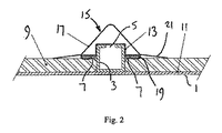
図1及び図2は床1を包含する車両構造体の一部分を示し、床1はこの床1に例えば溶接により取り付けられている、細長いC形部材3を有する。この細長いC部材3には、車両構造体の床下装備品(図示せず)を取り付けるための、細長くて下向きに向いているスロット5が設けられている。そして、長手方向に延びているフランジ7が、C形部材3の両側の各々に沿って設けられて、このC形部材から横向きに突出している。これらのフランジ7は溶接によりC形部材に取り付けることができるし、又はこれらのフランジ7は押し出し加工によりC形部材と一体に形成することもできる。代替的に、床1、C形部材3及びフランジ7は単一の押し出し品として一緒に形成することができる。図示されているように、フランジ7はC形部材3の各側部の高さにおけるほぼ中間のところに位置するようにされている。しかし、実際には、フランジ7はC形部材3の各側部の高さにおける都合のよい位置に位置させることができる。便宜上たった1つのC形部材が示されているけれども、実際には、複数の横に間隔を置いて離れているC形部材が設けられる。
1 and 2 show a portion of a vehicle structure that includes a floor 1, which has an elongated C-
防火障壁は耐火性及び熱絶縁性材料のパネル9を包含し、このパネル9は自立支持パネルであって、2つのC形部材3間に配置される。例えば、パネル9は、ひとつ又はそれ以上のガラス繊維、他の適当な織物材料又はアルミニウム箔から成るエンベロープの中に圧縮されて収容されている、微孔性のシリカをベースとした熱絶縁材料から成ることができる。代替的に、この圧縮した微孔性の熱絶縁材料はカバー無しにすることもできる。パネル9は、例えば、3〜25mmの厚さを有することができる。
The fire barrier includes a panel 9 of refractory and thermally insulating material, which is a self-supporting support panel and is disposed between two C-
パネル9は、その対向する両縁で、C形部材3に設けられたフランジ7により支持されると共に、接着フィルム11の手段により車両床1に取り付けられる。接着フィルム11は、例えば約250℃までの温度でも有効である感圧シリコーン接着剤をベースとしており、パネル9と実質的に同一の面積を有する。接着フィルム11は、パネル9と車両床1との間に配置されて、パネル9を車両床1に接着せしめる働きをなし、したがってフランジ7を越えての追加の支持体を提供する。接着フィルム11は、準備の段階において、その材料を加熱ローラを通して通過させることによりパネル9にラミネートすることができ、そして、それから、この得られた結合品を車両床1に取り付けることができる。
The panel 9 is supported by
C形部材3のスロット5は、膨張材料を担持している自己接着テープ13の手段により閉じられている。テープ13は、スロット5を覆うために任意適当な幅、例えば20mmから100mmまでの幅を有することができ、床下装備品のアイテム間においてC形部材3の下面にストリップの形で取り付けられる。図2から見ることができるように、膨張テープ13は、スロット5を包含する、C形部材3の下面の全体を覆ってかつC形部材3の両側壁及びフランジ7を覆って延びて、両側のフランジ7の自由端で終わっている。このような自己接着膨張テープ13のストリップを使用する利点は、車両構造体の組み立て中における都合によい時機にテープ13をC形部材3に取り付けることができること、及びテープ13の位置を床下装備品の位置に適合させることができ、これにより床下装備品の変形を容易にすることにある。火災の場合には、膨張材料が膨張してスロット5及びC形部材3を詰めて閉じ、これにより火がC形部材3に沿って広がるのを防止する。
The slot 5 of the C-
防火障壁の一体性を確保するために、防火障壁は更に複数の保持ばね部材15を包含し、これらの保持ばね部材15は膨張テープ13及びパネル9の両方を適所に保持する働きをする。
In order to ensure the integrity of the fire barrier, the fire barrier further includes a plurality of retaining
図1及び図2に示されている保持ばね部材15は、シートの形の材料から作られ、両側のフランジ7、膨張テープ13及びC形部材3のベース部を覆うV状部分17を包含する。V状部分17の両側の自由端の各々には更に2つの部分が形成されている。すなわち、第1の部分は膨張テープ13をフランジ7の自由端に対して保持するためにフランジ7の自由端のまわり及びフランジ7の反対側の側部に係合する曲げ部分19であり、また、第2の部分は外向きに延びている部分21であって、この部分21はその自由端がパネル9に対して偏倚されている。ばね部材15は、例えば、約10〜50mmの距離(ばね幅)にわたってC形部材3の長手方向へ延びることができ、また曲り部分19も約10〜50mmの長さを有することができ、更に外向きに延びている部分21も同じく約10〜50mmの長さを有することができる。ばね部材15は、任意適当な高温弾性材料、例えばばね鋼で作られる。そして、ばね部材15は、このばね部材をC形部材3にはさみ止め(クリップ)することにより又はC形部材3から抜き外し(アンクリップ)することにより、すなわち、いかなる工具を用いることなしに、人為的に取り付けたり又は取り外すことができる。このようなばね部材の使用は、防火障壁の取り付けをかなりスピードアップさせ、また重量を減少せしめ、更に例えばボルト及び/又はリベットのような追加の留め金具の必要性を除去する。更に、防火障壁を取り付け又は取り外すために車両構造体を逆にする必要もなく、防火障壁のための取り付け時間を更に減少せしめる。
The retaining
図示していないけれども、もし所望するならば、パネル9の外面には例えば金属シートのような耐候性コーティング又はカバーを設けることができる。 Although not shown, if desired, the outer surface of the panel 9 can be provided with a weathering coating or cover, such as a metal sheet.
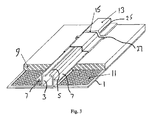
図3及び図4の実施形態は、図1及び図2の実施形態とは保持ばね部材15の形状のみが異なっている。図3及び図4の保持ばね部材15は、低プロフィルを有し、C形部材3の下(使用時)側部を覆って延びているキャップ部材23と、両側のフランジ7の各々の下(使用時)側部へと延びている、外向きに傾斜している部分25と、パネル9のための支持体を提供するためにフランジ7の下(使用時)側部に沿ってかつフランジ7の自由端を越える距離でフランジ7の自由端のまわりに延びていると共にフランジ7とパネル9との間でフランジ7の上(使用時)側部に沿って延びている曲り部分27とを包含する。ばね幅及び曲り部分の長さは、図1及び図2のばね幅及び曲り部分の長さと実質的に同じにすることができる。
The embodiment of FIGS. 3 and 4 differs from the embodiment of FIGS. 1 and 2 only in the shape of the holding
明らかに、保持ばね部材は、膨張テープ13及びパネル9を適所に保持する働きをすることを提供する他の形状を有することができる。
Obviously, the retaining spring member can have other shapes that serve to hold the
Claims (20)
前記平らな部材(1)に隣接して支持されていると共に前記平らな部材(1)と前記フランジ(7)のひとつとの間に延びている、耐火材料の複数のパネル(9)と、
前記C形部材(3)の前記細長いスロット(5)を覆っている、膨張材料(13)のシートと、
前記膨張材料(13)のシート及び前記耐火材料のパネル(9)を支持するために前記C形部材(3)のまわりに部分的に延びて前記フランジ(7)の裏に係合している弾性保持手段(15)と、
を包含することを特徴としている防火障壁。 A structure comprising a substantially flat member (1), said flat member (1) having an elongated, substantially C-shaped member (3) attached to the flat member; The C-shaped member (3) has a longitudinal slot (5) formed in the C-shaped member, and the C-shaped member (3) is substantially parallel to the flat member from the C-shaped member. In a fire barrier for a structure having flanges (7) on both sides, projecting laterally in the plane and extending longitudinally,
A plurality of panels (9) of refractory material supported adjacent to the flat member (1) and extending between the flat member (1) and one of the flanges (7);
A sheet of intumescent material (13) covering the elongated slot (5) of the C-shaped member (3);
Partially extends around the C-shaped member (3) and engages the back of the flange (7) to support the sheet of expandable material (13) and the panel of refractory material (9). Elastic holding means (15);
A fire barrier characterized by containing.
Applications Claiming Priority (2)
| Application Number | Priority Date | Filing Date | Title |
|---|---|---|---|
| GBGB0708545.9A GB0708545D0 (en) | 2007-05-03 | 2007-05-03 | Fire barrier |
| PCT/EP2008/003411 WO2008135190A1 (en) | 2007-05-03 | 2008-04-28 | Fire barrier |
Publications (1)
| Publication Number | Publication Date |
|---|---|
| JP2010525974A true JP2010525974A (en) | 2010-07-29 |
Family
ID=38198652
Family Applications (1)
| Application Number | Title | Priority Date | Filing Date |
|---|---|---|---|
| JP2010504565A Withdrawn JP2010525974A (en) | 2007-05-03 | 2008-04-28 | Fire barrier |
Country Status (9)
| Country | Link |
|---|---|
| EP (1) | EP2142410B1 (en) |
| JP (1) | JP2010525974A (en) |
| KR (1) | KR20100015536A (en) |
| CN (1) | CN101678838B (en) |
| AT (1) | ATE485206T1 (en) |
| DE (1) | DE602008003114D1 (en) |
| ES (1) | ES2353451T3 (en) |
| GB (1) | GB0708545D0 (en) |
| WO (1) | WO2008135190A1 (en) |
Families Citing this family (6)
| Publication number | Priority date | Publication date | Assignee | Title |
|---|---|---|---|---|
| JP5227298B2 (en) | 2009-12-16 | 2013-07-03 | 株式会社日立製作所 | Rail vehicle |
| CA2806886C (en) | 2013-02-20 | 2015-04-28 | Bombardier Transportation Gmbh | Heat resistant floor assembly for a rail vehicle |
| US9853262B2 (en) * | 2014-11-06 | 2017-12-26 | Ford Global Technologies, Llc | Battery pack retention assembly and retention method |
| ITUB20152549A1 (en) | 2015-07-28 | 2017-01-28 | Hitachi Rail Italy S P A | FLOOR STRUCTURE PROVIDED WITH A FIRE PROTECTION SYSTEM FOR RAIL VEHICLES |
| FR3092555B1 (en) * | 2019-02-11 | 2021-05-21 | Alstom Transp Tech | Frame and traction box, vehicle and associated manufacturing process |
| EP4140850A1 (en) * | 2021-08-31 | 2023-03-01 | 3A Composites Mobility AG | Fireproof floor structure of a car body in lightweight design |
Family Cites Families (5)
| Publication number | Priority date | Publication date | Assignee | Title |
|---|---|---|---|---|
| FR1417300A (en) * | 1964-09-30 | 1965-11-12 | Ferodo Sa | profiled construction elements |
| DE3115699A1 (en) * | 1981-04-18 | 1982-10-28 | Messerschmitt-Bölkow-Blohm GmbH, 8000 München | TRAINING OF THE FLOOR AREA OF VEHICLES WITH FASTENING DEVICES |
| GB2324816B (en) * | 1997-04-30 | 2001-03-14 | Exton | A fire break |
| DE19927006C2 (en) * | 1999-06-09 | 2001-05-10 | Daimler Chrysler Ag | Flooring for vehicles, in particular rail vehicles for the transportation of people |
| DE102005042682A1 (en) * | 2005-09-08 | 2007-03-22 | Daimlerchrysler Ag | Fastening device for e.g. vehicle seat, has panels integrated in U-shaped longitudinal support of vehicle base structure, where panels are designed as carrier-U-profile, which is designed as metallic roller profile |
-
2007
- 2007-05-03 GB GBGB0708545.9A patent/GB0708545D0/en not_active Ceased
-
2008
- 2008-04-28 CN CN2008800146881A patent/CN101678838B/en not_active Expired - Fee Related
- 2008-04-28 WO PCT/EP2008/003411 patent/WO2008135190A1/en active Application Filing
- 2008-04-28 EP EP08749184A patent/EP2142410B1/en not_active Not-in-force
- 2008-04-28 DE DE602008003114T patent/DE602008003114D1/en active Active
- 2008-04-28 AT AT08749184T patent/ATE485206T1/en not_active IP Right Cessation
- 2008-04-28 KR KR1020097021346A patent/KR20100015536A/en active IP Right Grant
- 2008-04-28 JP JP2010504565A patent/JP2010525974A/en not_active Withdrawn
- 2008-04-28 ES ES08749184T patent/ES2353451T3/en active Active
Also Published As
| Publication number | Publication date |
|---|---|
| KR20100015536A (en) | 2010-02-12 |
| WO2008135190A1 (en) | 2008-11-13 |
| EP2142410A1 (en) | 2010-01-13 |
| GB0708545D0 (en) | 2007-06-13 |
| ATE485206T1 (en) | 2010-11-15 |
| EP2142410B1 (en) | 2010-10-20 |
| DE602008003114D1 (en) | 2010-12-02 |
| ES2353451T3 (en) | 2011-03-02 |
| CN101678838A (en) | 2010-03-24 |
| CN101678838B (en) | 2012-03-28 |
Similar Documents
| Publication | Publication Date | Title |
|---|---|---|
| JP5542351B2 (en) | Chassis for rail vehicles with thermal insulation panels | |
| US11896859B2 (en) | Wall gap fire block device, system and method | |
| JP2010525974A (en) | Fire barrier | |
| US8353139B2 (en) | Wall gap fire block device, system and method | |
| US11230839B2 (en) | Thermal and acoustic insulating and sealing system for fluted deck constructions | |
| CA2784018C (en) | Thermal clip system and apparatus for a building wall assembly | |
| CA2433465A1 (en) | Passive fire protection system for walls | |
| ES2682461T3 (en) | Sound absorbing sandwich panel | |
| US10301818B1 (en) | Insulation support system | |
| JP2015048690A (en) | Waterproof sheet fixing structure | |
| US9428904B2 (en) | Modular joint barrier retainer assembly and method | |
| IES80741B2 (en) | A fire-retardant roof construction | |
| WO2015033174A1 (en) | Assembly, structure and method | |
| EP1111147A2 (en) | Structure of an arched and thermally and acoustically insulated monolithic panel, particularly useful for the roofing of industrial and civil buildings and the like | |
| CA2949413C (en) | Thermal insulating element and method for assembling a thermal insulating element on an interior surface of a rail vehicle | |
| US20230323657A1 (en) | Sealing device for edge joints and drywall | |
| EP2527555B1 (en) | Tile for a suspended ceiling system | |
| SE430085B (en) | DEVICE CARTRIDGE DEVICE | |
| GB2514072A (en) | Assembly, structure and method | |
| MXPA99006249A (en) | Fire barrier | |
| GB2529269A (en) | Insulation module | |
| PL67233Y1 (en) | Mounting profile |
Legal Events
| Date | Code | Title | Description |
|---|---|---|---|
| A300 | Application deemed to be withdrawn because no request for examination was validly filed |
Free format text: JAPANESE INTERMEDIATE CODE: A300 Effective date: 20110705 |