JP2010524375A - Vehicle communication system and communication system operation method - Google Patents
Vehicle communication system and communication system operation method Download PDFInfo
- Publication number
- JP2010524375A JP2010524375A JP2010502518A JP2010502518A JP2010524375A JP 2010524375 A JP2010524375 A JP 2010524375A JP 2010502518 A JP2010502518 A JP 2010502518A JP 2010502518 A JP2010502518 A JP 2010502518A JP 2010524375 A JP2010524375 A JP 2010524375A
- Authority
- JP
- Japan
- Prior art keywords
- communication system
- network
- data
- interface unit
- main operating
- Prior art date
- Legal status (The legal status is an assumption and is not a legal conclusion. Google has not performed a legal analysis and makes no representation as to the accuracy of the status listed.)
- Pending
Links
Images


Classifications
-
- H—ELECTRICITY
- H04—ELECTRIC COMMUNICATION TECHNIQUE
- H04L—TRANSMISSION OF DIGITAL INFORMATION, e.g. TELEGRAPHIC COMMUNICATION
- H04L12/00—Data switching networks
- H04L12/28—Data switching networks characterised by path configuration, e.g. LAN [Local Area Networks] or WAN [Wide Area Networks]
- H04L12/40—Bus networks
- H04L12/403—Bus networks with centralised control, e.g. polling
-
- H—ELECTRICITY
- H04—ELECTRIC COMMUNICATION TECHNIQUE
- H04L—TRANSMISSION OF DIGITAL INFORMATION, e.g. TELEGRAPHIC COMMUNICATION
- H04L12/00—Data switching networks
- H04L12/28—Data switching networks characterised by path configuration, e.g. LAN [Local Area Networks] or WAN [Wide Area Networks]
-
- H—ELECTRICITY
- H04—ELECTRIC COMMUNICATION TECHNIQUE
- H04L—TRANSMISSION OF DIGITAL INFORMATION, e.g. TELEGRAPHIC COMMUNICATION
- H04L12/00—Data switching networks
- H04L12/28—Data switching networks characterised by path configuration, e.g. LAN [Local Area Networks] or WAN [Wide Area Networks]
- H04L12/40—Bus networks
- H04L2012/40267—Bus for use in transportation systems
- H04L2012/40273—Bus for use in transportation systems the transportation system being a vehicle
Abstract
本発明は、車両(12)、特に、工業用または農業用の商用車両における通信システム(10)に関する。前記通信システム(10)は、少なくとも2つの主要動作コンポーネント(14)と、ネットワーク(16)とを備えている。車両(12)、そして好ましくは少なくとも1つの作業機能は、主要動作コンポーネント(14)によって動作させることができる。1つの主要動作コンポーネント(14)には、インターフェース・ユニット(32)と、主要動作コンポーネント(14)を作動させるおよび/または調整することができる任意の制御ユニットとが装備されている。1つの主要動作コンポーネント(14)上にあるインターフェース・ユニット(32)から、別の主要動作コンポーネント(14)上にあるインターフェース・ユニット(32)に、ネットワーク(16)を通じてデータを送信することができる。更に、本発明は、通信システム(10)の動作方法にも関する。簡略化したアーキテクチャおよび/またはより広い帯域幅を有する通信システムを設計するために、インターフェース・ユニット(32)に接続するネットワーク(16)には、イーサネット・データ・ネットワークが設けられている。
【選択図】図1The present invention relates to a communication system (10) in a vehicle (12), in particular an industrial or agricultural commercial vehicle. The communication system (10) comprises at least two main operational components (14) and a network (16). The vehicle (12), and preferably at least one work function, can be operated by the main operating component (14). One main operating component (14) is equipped with an interface unit (32) and an optional control unit capable of operating and / or adjusting the main operating component (14). Data can be transmitted over the network (16) from an interface unit (32) on one main operating component (14) to an interface unit (32) on another main operating component (14). . The invention further relates to a method of operating the communication system (10). In order to design a communication system with a simplified architecture and / or wider bandwidth, the network (16) connected to the interface unit (32) is provided with an Ethernet data network.
[Selection] Figure 1
Description
本発明は、車両、特に、工業用または農業用の商用車両における通信システムに関する。この通信システムは、少なくとも2つの主要動作コンポーネントと、ネットワークとを備えている。車両、そして好ましくは少なくとも1つの作業機能は、主要動作コンポーネントによって動作させることができる。主要動作コンポーネントは、インターフェース・ユニットを有し、更に主要動作コンポーネントを作動させるおよび/または調整するために用いることができる制御ユニットも有することができる。データおよび/または情報は、主要動作コンポーネント上にあるインターフェース・ユニットから、別の主要動作コンポーネント上にあるインターフェース・ユニットに、ネットワークと通じて送信することができる。また、本発明は、通信システムの動作方法にも関する。 The present invention relates to a communication system in a vehicle, in particular, an industrial or agricultural commercial vehicle. This communication system comprises at least two main operational components and a network. The vehicle, and preferably at least one work function, can be operated by the main operating component. The main operating component has an interface unit and can also have a control unit that can be used to operate and / or adjust the main operating component. Data and / or information may be transmitted over the network from an interface unit on one main operating component to an interface unit on another main operating component. The present invention also relates to a method of operating a communication system.
過去数十年の間に、電子回路ならびに電子コントローラおよびレギュレータの使用は、農業機械セクタにおいて徐々に重要になってきた。多くの用途は、簡略化することができ、一層効率的にそしてより良く動作し使用することができる。何故なら、電子コントローラは複数のプロセスを、手動動作で可能な場合よりも正確且つ素早く実行することができるからである。 During the past decades, the use of electronic circuits and electronic controllers and regulators has become increasingly important in the agricultural machinery sector. Many applications can be simplified and can be operated and used more efficiently and better. This is because the electronic controller can perform multiple processes more accurately and quickly than is possible with manual operation.
種々のコントローラは、それらのプロセスを互いに同調させ合い同期を取ることができ、必要なデータを互いに相互交換することができるように、これらはCANバスを通じて通信する。これは、シリアル・バス・システムであり、長年にわたって自動車および自動化工業において広く用いられてきる。CANバスは、理想的な条件の下で、1Mビット/Sまでのデータ送信レートに備えている。典型的なデータ送信レートは、125kビット/S、250kビット/S、および500kビット/Sである。 The various controllers communicate through the CAN bus so that their processes can be tuned and synchronized with each other and the necessary data can be exchanged with each other. This is a serial bus system and has been widely used in the automotive and automation industries for many years. The CAN bus provides for data transmission rates up to 1 Mbit / S under ideal conditions. Typical data transmission rates are 125 kbit / S, 250 kbit / S, and 500 kbit / S.
近年の車両システムにおける機能の範囲と共に増大しつつある大量のデータを送信および処理可能にするためには、複数のバスまたはバス・システムを並べて動作させる。前記バス・システムは、ゲートウェイによって互いに接続することができる。この結果、システムは増々複雑になり、問題を特定し解消することが増々困難になる。 In order to be able to transmit and process large amounts of data that is increasing with the range of functions in modern vehicle systems, multiple buses or bus systems are operated side by side. The bus systems can be connected to each other by a gateway. As a result, the system becomes more complex and it becomes increasingly difficult to identify and resolve problems.
農業機械設計におけるCAN通信の応用下位分野に、制御コマンドを相互交換する目的での、トラクタと機材(appliance)との間における通信がある。このために、製造業者相互国際規格(ISO11783またはISOBUS)があり、異なる製造業者からの機材およびトラクタが互いに通信できることを確保し、これを行うことができる様式および形態を示す。 CAN communication in agricultural machine design is a sub-field of communication between tractors and appliances for the purpose of exchanging control commands. To this end, there is a manufacturer's international standard (ISO11783 or ISOBUS), which ensures that equipment and tractors from different manufacturers can communicate with each other and shows the manner and form in which this can be done.
したがって、本発明は、文頭において引用した形式で、前述の問題を克服する通信システムの仕様を決定し開発する目的に基づく。即ち、その目的は、簡略化したアーキテクチャ、および/または帯域幅を広げた(higher)通信システムを提供することである。 Accordingly, the present invention is based on the objective of determining and developing a communication system specification that overcomes the aforementioned problems in the form cited at the beginning of the sentence. That is, the objective is to provide a simplified communication system and / or a higher communication system.
本発明は、この目的を、請求項1の特徴によって達成する。本発明の更に進んだ改良および発展は、従属請求項において見出すことができる。 The present invention achieves this object with the features of claim 1. Further improvements and developments of the invention can be found in the dependent claims.
本発明によれば、文頭において引用した形式の通信システムは、インターフェース・ユニットを接続するネットワークがイーサネット・データ・ネットワークを有するという点において格別である。 According to the invention, the communication system of the type cited at the beginning of the sentence is exceptional in that the network connecting the interface units has an Ethernet data network.
原則として、全ての主要動作コンポーネント間に、イーサネット・データ・ネットワークを設けることができる。あるいは、車両内において選択した主要動作コンポーネント間のみに、イーサネット・データ・ネットワークを設けることもできる。 In principle, an Ethernet data network can be provided between all major operating components. Alternatively, an Ethernet data network can be provided only between selected major operating components in the vehicle.
第1に、ISOBUSの可能性が最大限用いられている場合、前述のISO規格に基づくCANバスの利用することができることが認識されている。ISOBUSを通じて敷設する制御ループは、車両とそれに合わせて構成することができる器具との間の相互作用におけるワークフローの自動化のためのアプリケーションと全く同様に、前記ISOBUSの性能能力を超過する。加えて、用途によっては、現行のCANバスによって実現できる反応時間よりも短い反応時間を要求する場合もある。また、CANバスは応答時間が保証されていない。更に別の問題は、ISOBUSの範囲である。何故なら、付属機材の中には、物理的な理由のために、その測定値の寸法が、バスが許容するよりも大きくなることもあるからである。 First, it is recognized that a CAN bus based on the aforementioned ISO standard can be used when the ISOBUS potential is utilized to the fullest extent. The control loop laid through ISOBUS exceeds the performance capability of the ISOBUS, just as the application for workflow automation in the interaction between the vehicle and the equipment that can be configured accordingly. In addition, depending on the application, a reaction time shorter than that which can be realized by the current CAN bus may be required. Also, the response time of the CAN bus is not guaranteed. Yet another problem is the scope of ISOBUS. This is because, for some physical equipment, the dimensions of the measurements may be larger than the bus allows for some physical reasons.
したがって、工業用イーサネット・データ・ネットワークを、車両の主要動作コンポーネント間の通信のためのインフラストラクチャまたはプラットフォームとして用いることを、特に提案する。工業用イーサネット・データ・ネットワークは、工業用自動化ではほんの数年しか知られておらず、工業用生産プラントの製造業者および運営業者によって使用または応用されている。 Therefore, it is specifically proposed to use an industrial Ethernet data network as an infrastructure or platform for communication between the main operational components of a vehicle. Industrial Ethernet data networks are known for only a few years in industrial automation and are used or applied by manufacturers and operators of industrial production plants.
比較的高い帯域幅(100Mビット/Sまたは1Gビット/S)および比較的長い距離(銅線によって接続するときは100mまで)を考慮すると、比較的大量のデータを、全く問題なく、送信することも可能である。リアルタイム要求がある複雑な制御ループを動作させることを可能にするために、現在では、短いサイクル時間(例えば、数百マイクロ秒)の場合でも高い要求を満たす工業用イーサネット・データ・ネットワークに基づく、複数の異なるリアルタイム解決策がある。更に、工業用イーサネット・データ・ネットワークでは、車両の事務所および管理世界への連結を簡素化することができる。移動使用の特異性は、システムに対する要求の増大、したがって特に一般道路以外の区域(offroad area)における技術的課題を表す。リアルタイム互換ネットワークを実現するためには、例えば、正確時間プロトコル(IEEE1588)を用いることもできる。 Consider relatively high bandwidth (100 Mbit / S or 1 Gbit / S) and relatively long distances (up to 100 m when connected by copper wire), transmit relatively large amounts of data without any problems Is also possible. Based on an industrial Ethernet data network that now meets high demands even in the case of short cycle times (eg hundreds of microseconds) to enable operating complex control loops with real-time requirements, There are several different real-time solutions. Furthermore, industrial Ethernet data networks can simplify the connection of vehicles to the office and the management world. The idiosyncrasies of mobile use represent an increasing demand for the system and thus technical challenges, especially in offroad areas. In order to realize a real-time compatible network, for example, an accurate time protocol (IEEE 1588) can be used.
以下の車両コンポーネントは、本発明の想定においては、主要動作コンポーネントと見なされる。
−内燃エンジン
−トランスミッション
−液圧ポンプ
−電力引き取り軸
−電気機械を作動させるための変換器
−電力電子回路ユニット
−電気機械
−発電機
−電動機
−コンプレッサ
−特に能動的作動(active actuation)の場合における車両サスペンション・システム
言い換えると、主要動作コンポーネントは、移動(locomotion)または作業機能の実行というような、車両の必須機能遂行の実行のために通常比較的大量の電力引き出し即ち電力出力を要する、比較的大きなユニットまたは比較的大きなアセンブリである。
The following vehicle components are considered primary operational components in the context of the present invention.
--Internal combustion engine --Transmission --Hydraulic pump --Power take-up shaft --Converter for operating an electric machine --Power electronics unit --Electric machine --Generator --Electric motor --Compressor --Especially in the case of active actuation Vehicle Suspension System In other words, the primary motion component is a relatively high power draw or power output that usually requires a relatively large amount of power draw or power output to perform the essential functions of the vehicle, such as performing locomotion or work functions. A large unit or a relatively large assembly.
通信システムの一好適実施形態によれば、発電機における変換器が、インターフェース・ユニットを通じて、ネットワーク内に組み込まれている。加えて、電動機における変換器も同様に、インターフェース・ユニットを通じてネットワーク内に組み込まれている。少なくとも2つのインターフェース・ユニット間において、ネットワークはイーサネット・データ・ネットワークの形態をなし、特に、これはリアルタイム互換性があるので、発電機および電動機を互いに順番に動作させることができる。 According to one preferred embodiment of the communication system, the converter in the generator is integrated into the network through the interface unit. In addition, the converter in the motor is likewise integrated into the network through the interface unit. Between at least two interface units, the network is in the form of an Ethernet data network, in particular it is real-time compatible so that the generator and the motor can be operated in sequence with each other.
通信システムの更に別の好適な実施形態では、主要動作コンポーネントの個々のインターフェース・ユニットを作動させる通信システム・サーバが設けられている。個々のインターフェース・ユニットは、通信システム・サーバによって集中的に作動させることができ、これは、必ずしも星形ネットワーク構成となる必要はない。 In yet another preferred embodiment of the communication system, a communication system server is provided that operates the individual interface units of the main operating component. Individual interface units can be centrally operated by a communication system server, which need not necessarily be a star network configuration.
主要動作コンポーネントの一部、または制御ループの少なくとも1つの主要動作コンポーネントを作動させる場合、ネットワークを通じて送信するデータ・レートは1から数Mビット/Sの範囲であることが期待される。更に、このような制御ループは、非常に短い反応時間を必要とする可能性もある。したがって、通信システムの一好適実施形態では、リアルタイム互換データ送信を実現できるように、イーサネット・データ・ネットワークを設計する。 When operating part of the main operating component or at least one main operating component of the control loop, the data rate transmitted over the network is expected to be in the range of 1 to several Mbit / S. Furthermore, such control loops may require very short reaction times. Thus, in a preferred embodiment of the communication system, the Ethernet data network is designed so that real-time compatible data transmission can be achieved.
リアルタイム互換データ送信は、特に、規定可能な時間期間以内に少なくとも2つのインターフェース・ユニット間でデータ送信が行われる場合に実施することができ、規定可能な時間期間は、10μsから10msの範囲である。 Real-time compatible data transmission can be implemented in particular when data transmission takes place between at least two interface units within a definable time period, the definable time period being in the range of 10 μs to 10 ms. .
また、リアルタイム互換データ送信は、決定論的データ送信として知られているものの一部として実現することもできる。この場合、それぞれのデータ送信は、規定の時点において行われる。これは、個々のデータ・パケットの形態で設けることができる。典型的なサイクル時間は、約200μsであるが、これよりも短くてもよいことは確かである。ネットワーク加入者間のデータ送信は、このようなサイクル時間以内に終了する。 Real-time compatible data transmission can also be implemented as part of what is known as deterministic data transmission. In this case, each data transmission is performed at a specified time. This can be provided in the form of individual data packets. A typical cycle time is about 200 μs, but it can certainly be shorter. Data transmission between network subscribers is completed within such a cycle time.
加えてあるいは代わりに、リアルタイム互換データ送信は、少なくとも1つの別のインターフェース・ユニットに宛てたデータをインターフェース・ユニットが送る場合に行うことができる。この文脈では、最大時間期間は、送出側のインターフェース・ユニットによって規定することができる。あるいは、最大時間期間を別の方法で規定してもよい。この最大時間期間内に、データ送信成功の承認または検証が、受信側インターフェース・ユニットから受信されなければならない。 In addition or alternatively, real-time compatible data transmission can occur when the interface unit sends data addressed to at least one other interface unit. In this context, the maximum time period can be defined by the sending interface unit. Alternatively, the maximum time period may be defined by another method. Within this maximum time period, an acknowledgment or verification of successful data transmission must be received from the receiving interface unit.
また、リアルタイム互換データ送信は、少なくとも1つの別のインターフェース・ユニットに宛てたデータをインターフェース・ユニットが送り、送られたデータも実際に受信機によって、例えば、サイクル時間の後に受信された場合にも、行うことができる。このようなリアルタイム互換データ送信の設計は、異なる形態での静的用途のための先行技術から周知である。このような設計は、本願に対しても本質的に変更せずに採用することができ、あるいは本願に特定的に合わせることもできる。 Real-time compatible data transmission is also used when an interface unit sends data addressed to at least one other interface unit, and the transmitted data is also actually received by the receiver, for example after a cycle time. ,It can be carried out. Such real-time compatible data transmission designs are well known from the prior art for static applications in different forms. Such a design can be adopted for the present application essentially without change, or can be specifically adapted to the present application.
通信システムの一好適実施形態によれば、ネットワークは、以下のイーサネット規格の仕様に完全にまたは大方基づいて設計することができる。
−IEEE802.3(イーサネット)
−IEC SC5C(リアルタイム・イーサネット)
−IEEE802.11(WLAN)
−FlexRay
特に、IEC SC5C(リアルタイム・イーサネット)に基づいてイーサネット・データ・ネットワークを設計する場合、安全性が極めて重要な用途について既に証明されている規格に頼ることができるという利点がある。
According to one preferred embodiment of the communication system, the network can be designed completely or largely based on the following Ethernet standard specifications.
-IEEE802.3 (Ethernet)
-IEC SC5C (Real-time Ethernet)
-IEEE 802.11 (WLAN)
-FlexRay
In particular, when designing an Ethernet data network based on IEC SC5C (Real Time Ethernet), there is the advantage that it is possible to rely on standards that have already been proven for applications where safety is crucial.
ここでは、インターフェース・ユニットは、互いに、クライアントおよび/またはサーバとして、ネットワークを通じて通信することができる。加えてあるいは代わりに、マスタと少なくとも1つのスレーブとを有することはネットワークにとって役立つ場合がある。マスタは、特に規定の時刻に、要求データ・パケットを少なくとも1つのスレーブおよび/または全てのインターフェース・ユニットに、ネットワークを通じて送ることができる。これに関して、ネットワークにおけるデータ送信に対して周知のまたは定評のある概念に、これらの概念の内どれが本願にとって役に立つと思われるかに応じて、頼ることが可能である。 Here, the interface units can communicate with each other as a client and / or server over a network. In addition or alternatively, having a master and at least one slave may be useful for the network. The master can send request data packets over the network to at least one slave and / or all interface units, especially at a defined time. In this regard, it is possible to rely on well-known or well-established concepts for data transmission in the network, depending on which of these concepts seems useful for the present application.
これに関して、ネットワークを通じて送信するフレームにおけるフレーム・サイズまたはデータ・パケットのサイズも、規定可能および/または可変の形態とするとよい。好ましくは、フレーム・サイズは、送信する情報に基づいて、および/または時間に基づく送信密度に基づいて、可変に取り決めることができる。 In this regard, the frame size or data packet size in frames transmitted over the network may also be in a definable and / or variable form. Preferably, the frame size can be variably negotiated based on information to be transmitted and / or based on transmission density based on time.
通信システムの一好適実施形態によれば、インターフェース・ユニットは、マスタ/スレーブ・プロトコルに基づいて、ネットワークを通じて互いに通信する。特に、主要動作コンポーネントの個々のインターフェース・ユニットを集中的に作動させる通信システム・サーバが設けられている場合、この通信システム・サーバをマスタとして構成し、主要動作コンポーネント上のインターフェース・ユニットをスレーブとして構成すると役に立つ。 According to a preferred embodiment of the communication system, the interface units communicate with each other over a network based on a master / slave protocol. In particular, if there is a communication system server that centrally operates the individual interface units of the main operating component, this communication system server is configured as a master and the interface unit on the main operating component is a slave. It is useful to configure.
好ましくは、ネットワークは、少なくとも1Mビット/S、好ましくは10Mビット/S以上のデータ送信レートを有するような形態とする。
個々のインターフェース・ユニットは、ネットワークにおいて異なる方法で互いに接続することができる。この文脈では、異なるトポロジが役立つこともあり、少なくとも2つのインターフェース・ユニットまたは3つ以上のインターフェース・ユニットを互いに区間毎にそれぞれのトポロジで接続することを実質的に仮定する。特に好ましいのは、少なくとも2つのインターフェース・ユニットを線形トポロジで互いに接続することである。加えてあるいは代わりに、少なくとも2つのインターフェース・ユニットは、環状トポロジ、ツリー・トポロジ、および/または星形トポロジの形態で互いに接続することもできる。環状トポロジは特に有利である。何故なら、ネットワークが一地点で中断された場合でも、残りの団結した部分によって、データ送信が相変わらず可能であるからである。
Preferably, the network is configured to have a data transmission rate of at least 1 Mbit / S, preferably 10 Mbit / S or more.
Individual interface units can be connected to each other in different ways in the network. In this context, different topologies may be useful, substantially assuming that at least two interface units or more than two interface units are connected to each other in their respective topologies for each section. Particular preference is given to connecting at least two interface units together in a linear topology. Additionally or alternatively, the at least two interface units can be connected to each other in the form of a circular topology, a tree topology, and / or a star topology. An annular topology is particularly advantageous. This is because even if the network is interrupted at one point, data transmission can still be performed by the remaining united parts.
全ての主要動作コンポーネントまたはそのインターフェースおよび/または制御ユニットが互いにリアル・タイムで通信する必要がない場合、ネットワークの1区間だけがリアルタイム互換データ送信を有するような設備としてもよい。加えて、個々のネットワーク区間の最大データ送信レートは、特に、関連するインターフェース・ユニット間で通常予期されるデータ・トラフィックに特に基づいて、異なる値を有してもよい。 If all the main operating components or their interfaces and / or control units do not need to communicate with each other in real time, only one section of the network may be equipped with real-time compatible data transmission. In addition, the maximum data transmission rate of an individual network segment may have different values, particularly based on data traffic normally expected between associated interface units.
通信システムの一好適実施形態によれは、ネットワークは、車両に合わせて構成することができる器具まで及ぶ。車両が農業用商用車両、特に農業用トラクタの形態をなす場合、適した実現例は、一例として、鋤、ラウンド・ベーラ、噴霧器、ハロー、種まき機、および/または芝刈り機である。したがって、本発明の意味における器具とは、具体的には、作業機能を実行することができ、車両に合わせて可逆的に(reversibly)構成することができる機器である。車両と器具との間におけるネットワーク接続は、ケーブル・リンクおよび/または無線リンクによって実現することができる。車両のオンボード・ネットワークを、車両に合わせて可逆的に構成することができる器具まで延長することは、特に器具がインターフェース・ユニットを含む主要動作コンポーネントを有する場合には役に立つ。器具の主要動作コンポーネントは、例えば、電動機、またはこの電動機を作動させる変換器とすることができ、前記電動機は、例えば、飼料混合トラックにおいて混合スクリューを駆動することができる。電動機には、電源線を通じて電力を供給することができ、前記電力は、車両上に設けられる発電機によって生成し、飼料混合トラックに利用可能にすることができる。飼料混合トラックの電動機は、走行速度、分配する飼料、飼料混合トラック内にあるコンテナの充填状態、およびその他の動作パラメータに基づいて、適宜作動または調整することができる。器具および/または車両上にあるセンサからのセンサ・データも、ネットワークを通じて送信することができる。 According to one preferred embodiment of the communication system, the network extends to appliances that can be configured for the vehicle. If the vehicle is in the form of an agricultural commercial vehicle, in particular an agricultural tractor, suitable implementations are, by way of example, dredging, round balers, sprayers, halos, seeders and / or lawn mowers. Thus, an instrument in the sense of the present invention is specifically a device that can perform a work function and can be reversibly configured for the vehicle. The network connection between the vehicle and the appliance can be realized by a cable link and / or a wireless link. Extending the vehicle's on-board network to an instrument that can be reversibly configured for the vehicle is particularly useful when the instrument has major operating components including an interface unit. The main operating component of the instrument can be, for example, an electric motor or a converter that operates the electric motor, which can drive a mixing screw, for example, in a feed mixing truck. Electric power can be supplied to the electric motor through a power line, and the electric power can be generated by a generator provided on the vehicle and made available to the feed mixing truck. The electric motor of the feed mixing truck can be appropriately operated or adjusted based on the traveling speed, the feed to be distributed, the filling state of the containers in the feed mixing truck, and other operating parameters. Sensor data from appliances and / or sensors on the vehicle can also be transmitted over the network.
ネットワークは、装置データを送信するために用いることができ、これらは特に、ネットワーク上にある個々のインターフェース・ユニットの登録に関するデータとすることができる。加えて、インターフェースの識別に関するデータ、あるいはインターフェース・ユニットおよび主要動作コンポーネントからの特性データ、あるいはこれらのコンポーネントからのプリセット・パラメータおよび/またはステータス・データも考慮に入る。 The network can be used to transmit device data, which can in particular be data relating to the registration of individual interface units on the network. In addition, data relating to the identification of the interface, or characteristic data from the interface unit and main operating components, or preset parameters and / or status data from these components are also taken into account.
代わりにあるいは加えて、ネットワークは、プロセス・データを送信するために用いることができる。プロセス・データとは、具体的には、主要動作コンポーネントへのコマンド・データ、主要動作コンポーネントからの入力データ、主要動作コンポーネントからのパラメータ、および/またはセンサ・データとすることができる。特に好ましくは、これらは、発電機と電動機との間において、発電機の中にある変換器と電動機の中にある変換器との間で送信する必要がある、電力流についての調整データとするとよい。この場合、発電機および電動機の双方共、車両上に配置することができる。代わりにあるいは加えて、発電機を車両上に配置し、電動機を、車両に合わせて構成することができる器具上に配置することも着想することができる。 Alternatively or additionally, the network can be used to transmit process data. The process data may specifically be command data to the main operating component, input data from the main operating component, parameters from the main operating component, and / or sensor data. Particularly preferably, these are the adjustment data on the power flow that need to be transmitted between the generator and the motor between the converter in the generator and the converter in the motor. Good. In this case, both the generator and the electric motor can be arranged on the vehicle. Alternatively or additionally, it is also conceivable to arrange the generator on the vehicle and the electric motor on an appliance that can be configured for the vehicle.
また、ネットワークを通じて、エラー・メッセージを送信できるようにすることも可能である。これらは、特に、エラーの時刻、エラーの種類、エラーの理由、および/または主要動作コンポーネントの状態を含むとよい。 It is also possible to send error messages over the network. These may include, among other things, the time of the error, the type of error, the reason for the error, and / or the state of the main operating component.
とりわけ、診断データを送るためにネットワークを用いることが可能であり、診断データは、特に、主要動作コンポーネントからの動作状態および/またはパラメータを有する。 In particular, it is possible to use a network to send diagnostic data, which diagnostic data has in particular operating conditions and / or parameters from the main operating components.
通信システムの特に好ましい一実施形態では、インターフェース・ユニットは、単一チップ技術に基づく。この場合、特に、主要動作コンポーネントのネットワーク通信および作動を、半導体チップに組み合わせる。これによって、第1に簡潔な設計が可能となり、第2にほぼエラーのない信頼性が高いネットワーク動作が可能となる。何故なら、用いる必要がある別個のコンポーネントは数個に過ぎないからである。 In a particularly preferred embodiment of the communication system, the interface unit is based on single chip technology. In this case, in particular, the network communication and operation of the main operating components are combined into a semiconductor chip. This allows first a simple design and secondly a highly reliable network operation with almost no errors. This is because there are only a few separate components that need to be used.
好ましくは、ネットワーク動作の最中にインターフェース・ユニットを追加または除去することができる。ネットワークのこのような固有性は、「ホット・プラグ」という用語でも呼ばれており、特に、器具が車両に合わせて構成されており、ネットワークが器具まで及んでいる場合に役に立つ。この場合、器具の主要動作コンポーネント上にあるインターフェース・ユニットは、ネットワーク動作の最中に車両ネットワーク上に登録することができ、続いてネットワークを通じて作動させることができる。 Preferably, interface units can be added or removed during network operation. This uniqueness of the network is also called the term “hot plug” and is particularly useful when the appliance is configured for the vehicle and the network extends to the appliance. In this case, the interface units on the main operational component of the appliance can register on the vehicle network during network operation and can subsequently be activated through the network.
特に、農業用器具即ちトラクタの場合、器具を頻繁に変えて、例えば、更に別のインターフェース・ユニットをネットワークに接続するためにネットワークの電力を落としたり、この時間中には車両の限られた機能しか利用可能できなくする必要がないようにしている。 Especially in the case of agricultural equipment or tractors, the equipment is frequently changed, for example to turn off the network to connect another interface unit to the network, or during this time the limited functionality of the vehicle It only needs to be unavailable.
好ましくは、ネットワークへの不正アクセスを防止するために用いることができる少なくとも1つの対策を設ける。このような対策は、ファイアウオール、プログラム・ルーチン、パスワード・チェック、ユーザ権利管理、および/または暗号化方法を有することができる。これに関して、既存のメカニズムまたは規格に頼ることができる。 Preferably, at least one measure is provided that can be used to prevent unauthorized access to the network. Such countermeasures can include firewalls, program routines, password checks, user rights management, and / or encryption methods. In this regard, existing mechanisms or standards can be relied upon.
特に好ましくは、ネットワークの個々のコンポーネントをファイル・システムにマッピングするために用いることができる手段を設ける。このような手段は、特に、ルーチン、あるいはNFS、FPT、SFTP、RSH、SSH、Telnet、Rloginおよび/またはX−Windowsを含むことができる。したがって、一例として、通信システムを単純なファイル・システムの形態で外部に対して表現することができる。この設計は、車両用「仮想サーバ」と呼ぶことができる。 Particularly preferably, means are provided that can be used to map individual components of the network to the file system. Such means may in particular include routines or NFS, FPT, SFTP, RSH, SSH, Telnet, Rlogin and / or X-Windows. Therefore, as an example, the communication system can be expressed to the outside in the form of a simple file system. This design can be referred to as a “virtual server” for vehicles.
これに関して、例えば、通信システム・サーバを通じて新たなソフトウェアおよび/または変更したソフトウェアを集中的にロードすることが可能になる。これは、個々のインターフェース・ユニットおよび個々の主要動作コンポーネントの新たなファームウェアにも当てはまる。この場合、個々のデータまたはファイルの実際の物理的記憶位置を知る必要はない。何故なら、前記記憶位置は、例えば、通信システム・サーバによって調整されるからである。適したアドレシングが必要条件となろう。 In this regard, for example, new and / or modified software can be centrally loaded through the communication system server. This is also true for new firmware for individual interface units and individual key operating components. In this case, it is not necessary to know the actual physical storage location of individual data or files. This is because the storage location is adjusted by the communication system server, for example. Appropriate addressing will be a requirement.
加えて、これによって、イーサネット・データ・ネットワークの全てのサービスおよび機能を原則として実現し用いることが可能となる。特に、一般道路以外の区域のためのネットワークの実現例に関しては、本願では、イーサネット・データ・ネットワークは、その信頼性がありロバストなネットワークという固有性を考慮すると、しかるべきインターフェース・ユニットを通じた車両の個々の主要動作コンポーネント間における通信に適していることが好ましい。 In addition, this makes it possible in principle to implement and use all services and functions of the Ethernet data network. In particular, with regard to network implementations for areas other than general roads, in this application, the Ethernet data network is considered to be a vehicle through an appropriate interface unit in view of its uniqueness as a reliable and robust network. It is preferably suitable for communication between the individual main operating components.
個々のインターフェース・ユニットおよび/または通信システム・サーバのために提供するオペレーティング・システムは、UnixまたはUnix派生物とするとよい。これは、マルチタスキング互換オペレーティング・システムであり、リアルタイム処理能力も装備することができる。あるいは、個々のインターフェース・ユニットおよび/または通信システム・サーバのために提供するオペレーティング・システムは、Microsoft Windowsまたはしかるべき派生物としてもよい。 The operating system provided for individual interface units and / or communication system servers may be Unix or a Unix derivative. This is a multitasking compatible operating system and can also be equipped with real-time processing capabilities. Alternatively, the operating system provided for individual interface units and / or communication system servers may be Microsoft Windows or a suitable derivative.
ネットワーク・コンポーネント上で走るオペレーティング・システムには関わらず、車両ユーザには、グラフィカルおよび/またはマルチメディア・ユーザ・インターフェース(GUI)を設けることができる。これは、用いるのが簡単で直観的であり、車両を動作させるために必要な情報をユーザに提供する。この場合、グラフィカル・ユーザ・インターエースは、広く用いられているユーザ方式「ルック&フィール」(Look & Feel)の異なる形態と一致するとよい。これらの例は、Microsoft WindowsまたはAppleからのオペレーティング・システムのユーザ・インターフェースから周知である。Unixオペレーティング・システム、特にLinuxは、KDEまたはGNOMEと呼ばれるシステムを、ユーザ・インターフェースとして提供する。これらのユーザ・インターフェースは、個々に構成することができる。これが意味するのは、これらも、例えば、オペレーティング・システムMicrosoft Windowsの「ルック&フィール」を有することができるということである。 Regardless of the operating system running on the network component, the vehicle user can be provided with a graphical and / or multimedia user interface (GUI). This is easy to use and intuitive and provides the user with the information necessary to operate the vehicle. In this case, the graphical user interface may coincide with a different form of the widely used user method “Look & Feel”. Examples of these are well known from operating system user interfaces from Microsoft Windows or Apple. The Unix operating system, in particular Linux, provides a system called KDE or GNOME as a user interface. These user interfaces can be configured individually. This means that they can also have, for example, the “look and feel” of the operating system Microsoft Windows.
特に好ましくは、通信システムは、少なくとも他の1つのネットワークおよび/またはセクタ特定ソフトウェアの1つおよび/または工業用または農業用商用車両を管理するソフトウェアの1つへのインターフェースを有する。この種の別のネットワークは、例えば、中央コンピュータ・システムを内部に備えた、農業経営(agricultural operation)からの基本ネットワークとするとよい。このようなコンピュータ・システムは、セクタ特定プログラムがインストールされており、農業経営の作業を処理し、管理し、および/または統計的に評価するために用いることができる。特に、このような他のネットワークへのインターフェースにより、事務所用アプリケーションおよびマルチメディア・アプリケーションを、車両のネットワークに統合することが可能になり、あるいはこれとデータを伝達または相互交換することが可能になる。 Particularly preferably, the communication system has an interface to at least one other network and / or one of the sector specific software and / or one of the software managing industrial or agricultural commercial vehicles. Another network of this kind may be, for example, a basic network from agricultural operation with a central computer system inside. Such a computer system has a sector specific program installed and can be used to process, manage and / or statistically evaluate farming operations. In particular, such interfaces to other networks allow office applications and multimedia applications to be integrated into the vehicle network, or to communicate or exchange data with it. Become.
前述した他のネットワークは、具体的には、次のネットワーク仕様の1つにそれぞれ完全にまたはほぼ準拠する。
−IEEE802.15.1(Bluetooth)
−IEEE802.15.4(ZigBee)
−IEEE802.1(WiMAX)
−GPS
−USB
−UMTSまたはGSM。
Specifically, the other networks described above are each fully or nearly compliant with one of the following network specifications:
-IEEE802.15.1 (Bluetooth)
-IEEE802.15.4 (ZigBee)
-IEEE 802.1 (WiMAX)
-GPS
-USB
-UMTS or GSM.
以下の文章は、本発明による通信システムの利点を纏めたものである。つまり、本発明による通信システムは、相応の用途例に基づいて、従来技術と比較すると、高速化したデータ送信を有し、拡大した帯域幅を提供する。制御ユニットおよび/またはインターフェース・ユニットおよび/または主要動作コンポーネントのための制御および調整プログラムは、更に、より簡単にそしてより素早く開発することができる。何故なら、各単一制御ユニットの場合に、ときとして具体的なインターフェースに明示的に接続する必要なく、単純で、自動化した、包括的なプログラミングが可能であるからである。通信システム・サーバに直接ログ・インし、そこから、ネットワークを通じて互いに接続されている全てのコンポーネントにアクセスすることができる。 The following text summarizes the advantages of the communication system according to the present invention. In other words, the communication system according to the present invention has an increased data transmission and provides an increased bandwidth compared to the prior art based on a corresponding application example. Control and adjustment programs for control units and / or interface units and / or main operating components can be further developed more easily and more quickly. This is because in the case of each single control unit, simple, automated and comprehensive programming is possible, sometimes without the need to explicitly connect to a specific interface. You can log in directly to the communication system server and from there you can access all the components connected to each other through the network.
これに関して、ユーザ権利の割り当ておよび/またはユーザ権利の管理を用いることができる。診断の選択肢に関しても、先行技術から周知のシステムと比較すると、改良を達成することができる。何故なら、診断データをより高いレートで送信することができるからである。通信システムは、コンポーネント、ネットワーク・プロトコル、および概念で設計することができ、これらを切り離すと、比較的長い時間知られており、設計に関しては優れていることが実証されている。これによって、特に、安全で高速なネットワーク通信が可能となる。これは利用可能な技術であり、標準的なコンポーネントは、大量に低材料コストで入手可能である。特に時間が極めて重要な用途および/または安全性に関係する用途に対して保証されている規格を用いることができる。 In this regard, user rights assignment and / or user rights management can be used. With regard to diagnostic options, improvements can also be achieved when compared to systems known from the prior art. This is because diagnostic data can be transmitted at a higher rate. Communication systems can be designed with components, network protocols, and concepts that, apart, have been known for a relatively long time and have proven to be excellent in design. This enables particularly safe and high-speed network communication. This is an available technology, and standard components are available in large quantities at low material costs. Standards guaranteed for time critical applications and / or safety related applications can be used.
方法に関して、文頭においてあげた目的は、請求項34の特徴によって達成する。したがって、本発明による方法は、車両において通信システムを動作させるために用いることができる。通信システムは、特に、請求項1から33の1つに基づいて設計する。通信システムは、少なくとも2つの主要動作コンポーネントとネットワークとを備えている。主要動作コンポーネントによって車両を動作させる。主要動作コンポーネントは、インターフェース・ユニットと、可能であれば、主要動作コンポーネントを作動および/または調整するために用いられる制御ユニットとを有する。1つの主要動作コンポーネント上にあるインターフェース・ユニットから別の主要動作コンポーネント上にあるインターフェース・ユニットへ、ネットワークを通じてデータを送信する。インターフェース・ユニットを接続するネットワークは、イーサネット・データ・ネットワークを有する。
With regard to the method, the object mentioned at the beginning of the sentence is achieved by the features of
本発明による方法は、請求項1から34の1項に記載の通信システムを車両において動作させるのに適しているので、本発明の分野において活動する当業者であれば、請求項1から34のいずれか1項に記載の通信システムを参照することにより、本発明による方法の有利な改良および発展への糸口をつかめる。これに関して、繰り返しを避けるために、この説明の直前部分を引用する。 The method according to the invention is suitable for operating a communication system according to one of claims 1 to 34 in a vehicle, so that a person skilled in the art working in the field of the invention By referring to the communication system according to any one of the claims, the clues to advantageous improvements and developments of the method according to the invention can be found. In this regard, in order to avoid repetition, we quote the part immediately before this description.
ここで、本発明の教示を有利に改良し発展させるための様々な選択肢がある。このため、図面を参照しながら最初に従属請求項に言及し、次いで本発明の好ましい実施形態例の以下の説明に言及する。一般に、好ましい改良や発展も、本発明の好ましい実施形態例の記載と合わせて、図面を参照しながら説明する。 There are now various options for advantageously improving and developing the teachings of the present invention. For this reason, reference is first made to the dependent claims with reference to the drawings, and then to the following description of preferred exemplary embodiments of the invention. In general, preferred improvements and developments will be described with reference to the drawings in conjunction with the description of preferred embodiments of the invention.
これらの図において、同一または同様のコンポーネントは、同じ参照符号によって特定することとする。 In these figures, identical or similar components will be identified by the same reference numerals.
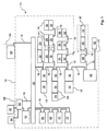
図1は、車両12における通システム10を示す。車両12は、トラクタの形状、即ち、農業用商用車両の形態をなす。図1において、破線の枠12は、単に、車両12と関連のあるコンポーネントを示すに過ぎない。通信システム10は、複数の主要動作コンポーネント14と、ネットワーク16とを備えている。車両12は、主要動作コンポーネント14によって動作させることができる。
FIG. 1 shows a
図1に示す実施形態例に設けられている主要動作コンポーネント14は次の通りである。内燃エンジン18、トランスミッション20、液圧装置22、発電機24と関連付けられている変換器25を有する発電機24、および各々電動機または発電機として動作させることができる複数の電気機械である。具体的には、冷却装置においてクーラ(図示せず)のためにファン(図示せず)を駆動するために用いられるのは電気機械26である。電気機械28は、空調装置においてコンプレッサ(図示せず)を駆動する。変換器30は、電気インターフェース(図示せず)を用いて、車両に合わせて構成されている、器具(implement)40に電力をそれぞれに要求される形態で供給する。これは、直流、交流、または規定可能な周波数の三相交流でもよい。ネットワーク16は、したがって、具体的にはケーブル・リンクを通じておよび/または無線リンクを通じて、車両12に合わせて構成することができる器具40にまで及ぶ。器具40は、主要動作コンポーネント44およびインターフェース・ユニット46を有する・インターフェース・ユニット46は、ネットワーク動作の最中でもネットワーク16に追加すること、またはネットワーク16から取り外すことができる。診断システム52も、ネットワーク動作の最中にネットワーク16に接続することができる。診断システム52は、ネットワーク16に接続されているコンポーネントを診断するために用いることができる。
The main
前述の主要動作コンポーネント14は、各々、インターフェース・ユニット32を有する。インターフェース・ユニット32は、それぞれの主要動作コンポーネント14を作動および/または調整するために用いることができる。図1に示す通信システム10では、データは、一方の主要動作コンポーネント14上にあるインターフェース・ユニット32から、別の主要動作コンポーネント14上にあるインターフェース・ユニット32に、ネットワーク16を通じて送信することができる。
Each of the main
加えて、ネットワーク16は、それに接続されているコンポーネントを有し、この実施形態例では、主要動作コンポーネントとは見なされないが、重要な車両機能または作業機能を作動させる。具体的には、これらは電磁的に作動可能な液圧弁34、個別センサ36、および個別液圧アクチュエータ38である。これらのコンポーネントは、それぞれ、インターフェース・ユニット32と関連付けられており、インターフェース・ユニット32はネットワーク16を通じてこれらのコンポーネントを作動させるために用いることができる。
In addition, the
本発明によれば、インターフェース・ユニット32を接続するネットワーク16は、イーサネット・データ・ネットワークを有する。
通信システム・サーバ42を用いて、主要動作コンポーネント14の個々のインターフェース・ユニット32を作動させる。通信システム・サーバ42は、ネットワーク16とのダイアローグ(dialog)に関する限り、マスタとして構成されている。インターフェース・ユニット32は、ネットワーク動作についてはスレーブとして構成されている。したがって、マスタ/スレーブ・プロトコルが、通信システム・サーバ42とインターフェース・ユニット32との間において用いられる。
According to the present invention, the
A
少なくとも変換器25のインターフェース・ユニット32と電気機械26、28および変換器30との間にあるネットワーク16の部分は、IEC SC5Cに基づく仕様に従ったリアルタイム互換イーサネット・データ・ネットワークの形態をなす。これによって、これらのインターフェース・ユニット32と関連のある主要動作コンポーネント25、26、28、30との間において、リアルタイム互換データ送信が可能となる。ネットワーク16は、100Mビット/S以上のデータ送信レートを有する。
At least the portion of the
車両のユーザには、モニタおよびユーザ・ユニット48上に、グラフィカルおよびマルチメディア・ユーザ・インターフェースが設けられている。これによって、ユーザは車両12またはその主要動作コンポーネント14についての現行状態データを読み取り、車両12の動作の個々のモードを活性化および/または不活性化することができる。このために、制御およびインターフェース・ユニット49が設けられており、ユーザと車両12の通信システム・サーバ42との相互作用を実行するために用いることができる。
Vehicle users are provided with graphical and multimedia user interfaces on the monitor and
ネットワーク16は、他のネットワークに対して複数のインターフェースを有する。つまり、診断システム52が接続されているインターフェース50が設けられている。インターフェース50、したがってネットワーク16は、主要動作コンポーネント14から診断データを送信するために用いることができ、診断データは、特定的な動作状態および/またはパラメータを有する。
The
加えて、車両12が、例えば、ディーラ、修理工場のコンピュータ・システム、および/またはユーザに属する基本的コンピュータ・システムに接続するために用いることができるインターフェース54も設けられている。このためのプログラム・ルーチンを実行し、外部コンピュータ・システムとの通信のための車両特定データを調整する(condition)車両コンピュータ・ユニットが、参照符号53によって示されている。この種の外部コンピュータおよび/またはネットワーク・システムは、参照符号56によって模式的に示すのみとする。インターフェース54は、ケーブル・リンクおよび従来のイーサネット・リンクとすることができる(車両は、工場(garage)においてネットワーク・ケーブルによって接続する)。しかしながら、インターフェース54は、IEEE802.11(WLAN)またはIEEE802.16(WiMAX)に基づく仕様に準拠して設計する無線リンクの形態をなすこともできる。
In addition, an
車両12は、車両ナビゲーション・システム62を有する。車両ナビゲーション・システム62は、インターフェース58または無線リンクを用いて、少なくとも1機の衛星60からGPS測地信号を受信することができる。また、車両ナビゲーション・システム62は、インターフェース58を用いて基地局64と通信することもできる。基地局64も同様に測地信号を送り、現場の端縁(edge)に位置付けることができるので、現場作業の最中に、トラクタの形態をなす車両12の位置発見を、一層精度高く行うことが可能である。
The
参照番号66から72は、安全性に関する制御ユニットを示し、これらは車両12を操縦および制動するために用いることができる。これに関係するネットワーク16の部分は、リアルタイム互換イーサネット・データ・ネットワークによって、通信システム・サーバ42に環状トポロジで接続されている。リアルタイム互換イーサネット・データ・ネットワークは、安全性が極めて重大なデータ送信のための仕様、例えば、TTP(時間誘起プロトコル:Time Triggered Protocol)またはFlexRayに準拠する。
Reference numbers 66 to 72 indicate safety control units that can be used to steer and brake the
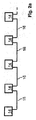
図2aは、線形トポロジの形態で互いに接続されている主要動作コンポーネント(図2から図2dには示されていない)に合わせた複数のインターフェース・ユニット32を示すために模式図を用いる。図2bは、ツリー・トポロジの形態で互いに接続されている主要動作コンポーネントに合わせた複数のインターフェース・ユニット32の模式図を示す。個々のインターフェース・ユニット32は、区間内では、線形トポロジで互いに接続されている。図2cは、星形トポロジの形態で互いに接続されている主要動作コンポーネントのインターフェース・ユニット32の模式図を示す。図2dは、環状トポロジの形態で互いに接続されている主要動作コンポーネントのインターフェース・ユニット32の模式図を示す。好ましくは、車両12における少なくとも区間単位で線形トポロジおよび/または環状トポロジを用いる。図1および図2aから図2dにおけるインターフェース・ユニット32は、単一チップ技術に基づいている。
FIG. 2a uses a schematic diagram to show a plurality of
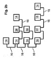
図3は、例えば、図1に示す通信システム10に用いることができる、サーバ構成の実施形態例を示すために、模式図を用いる。この場合、個々の矩形は、ファイル・システムの部分74を示す。ファイル・システムは、個々の関連システム・データおよび/またはプログラム・モジュールを格納する。ファイル・システムのそれぞれの経路表現(path statement)は、一例として、それぞれの部分74の上に示されている。
FIG. 3 uses a schematic diagram to illustrate an example embodiment of a server configuration that can be used, for example, in the
図3に示すファイル・システムの構成に基づけば、通信システム・サーバ42によって集中的に新たなソフトウェアおよび/または変更したソフトウェアをロードすることができるという利点がある。
Based on the configuration of the file system shown in FIG. 3, there is an advantage that new and / or changed software can be loaded centrally by the
個々のインターフェース・ユニット32および/または通信システム・サーバ42に設けられるオペレーティング・システムは、Unix派生物、即ち、Linuxである。
ネットワーク16に対する不正アクセスを防止するために用いることができる対策76が設けられている。これらの対策76は、それぞれ、ファイアウオールの形態となっている。
The operating system provided in the
A
最後に、以上で論じた実施形態例は、特許請求する教示を説明する役割を果たすだけであり、実施形態例に限定するのではないことを、特別に指摘しておく。 Finally, it is specifically pointed out that the example embodiments discussed above serve only to explain the claimed teachings and are not limited to the example embodiments.
Claims (34)
Applications Claiming Priority (3)
| Application Number | Priority Date | Filing Date | Title |
|---|---|---|---|
| DE102007016804 | 2007-04-12 | ||
| DE102007056318A DE102007056318A1 (en) | 2007-04-12 | 2007-11-22 | Communication system of a vehicle and method for operating a communication system |
| PCT/EP2008/054405 WO2008125614A2 (en) | 2007-04-12 | 2008-04-11 | Vehicle communication system, and method for the operation of a communication system |
Publications (2)
| Publication Number | Publication Date |
|---|---|
| JP2010524375A true JP2010524375A (en) | 2010-07-15 |
| JP2010524375A5 JP2010524375A5 (en) | 2013-09-12 |
Family
ID=39744363
Family Applications (1)
| Application Number | Title | Priority Date | Filing Date |
|---|---|---|---|
| JP2010502518A Pending JP2010524375A (en) | 2007-04-12 | 2008-04-11 | Vehicle communication system and communication system operation method |
Country Status (8)
| Country | Link |
|---|---|
| EP (2) | EP2137030A2 (en) |
| JP (1) | JP2010524375A (en) |
| KR (1) | KR20100015510A (en) |
| CN (1) | CN101652270B (en) |
| BR (1) | BRPI0809449A2 (en) |
| DE (1) | DE102007056318A1 (en) |
| MX (1) | MX2009010005A (en) |
| WO (1) | WO2008125614A2 (en) |
Cited By (2)
| Publication number | Priority date | Publication date | Assignee | Title |
|---|---|---|---|---|
| JP2014521538A (en) * | 2011-04-21 | 2014-08-28 | ディーア・アンド・カンパニー | Data communication interface for agricultural utility vehicles |
| US11497155B2 (en) | 2018-04-27 | 2022-11-15 | Kubota Corporation | Generator unit and working machine |
Families Citing this family (22)
| Publication number | Priority date | Publication date | Assignee | Title |
|---|---|---|---|---|
| DE102011112707B4 (en) | 2011-09-07 | 2020-11-05 | Volkswagen Aktiengesellschaft | Display device for a hybrid vehicle and method for display and hybrid vehicle |
| EP2587752B1 (en) * | 2011-10-27 | 2014-05-07 | Siemens Aktiengesellschaft | Data exchange in a transport system using positive and negative half-waves of an alternating signal for transmitting the data |
| NL2009105C2 (en) * | 2012-07-02 | 2014-01-06 | Mci Mirror Controls Int Nl Bv | ADJUSTMENT SYSTEM, PRIMARY SERVICE UNIT AND SECONDARY SERVICE UNIT. |
| KR102004926B1 (en) * | 2012-11-06 | 2019-07-29 | 한국전자통신연구원 | Frame conversion apparatus for converting Controller Area Network frame to Ethernet frame and frame conversion method threrof |
| DE102013101502A1 (en) | 2013-02-14 | 2014-08-14 | Knorr-Bremse Systeme für Schienenfahrzeuge GmbH | Air supply system with electronic converter |
| KR101491260B1 (en) | 2013-06-07 | 2015-02-06 | 현대자동차주식회사 | ECU Multiple Diagnostic System and Method on Vehicle Network |
| KR101500094B1 (en) | 2013-07-01 | 2015-03-06 | 현대자동차주식회사 | Message transmission/reception system and method for ethernet-based vehicle network |
| DE102013214577A1 (en) * | 2013-07-25 | 2015-01-29 | Continental Automotive Gmbh | Monitoring and diagnosis of a control unit |
| US20150135271A1 (en) * | 2013-11-11 | 2015-05-14 | GM Global Technology Operations LLC | Device and method to enforce security tagging of embedded network communications |
| KR101443276B1 (en) * | 2013-11-21 | 2014-09-22 | 현대자동차주식회사 | Control unit for in-vehicle ethernet and method for controlling therof |
| US9118651B2 (en) | 2013-11-22 | 2015-08-25 | Hyundai Motor Company | Control unit for in-vehicle ethernet and method for controlling thereof |
| KR101512401B1 (en) * | 2013-12-17 | 2015-04-15 | 주식회사 경신 | An apparatus and a method for controlling a ECU of a vehicle, and a system for controlling the ECU of the vehicle with the apparatus |
| DE102013227059A1 (en) * | 2013-12-23 | 2015-06-25 | Robert Bosch Gmbh | METHOD FOR DETERMINISTIC DATA TRANSMISSION IN A BUS SYSTEM AND BUS SYSTEM |
| US10126754B2 (en) * | 2014-02-06 | 2018-11-13 | Yanmar Co., Ltd. | Method for setting travel path of work vehicle |
| CN104163151B (en) * | 2014-08-22 | 2016-09-07 | 东南(福建)汽车工业有限公司 | A kind of whole vehicle bus control system |
| ITUA20161643A1 (en) * | 2016-03-14 | 2017-09-14 | Iveco Magirus | VEHICLE ARCHITECTURE |
| CN105882566A (en) * | 2016-04-20 | 2016-08-24 | 徐州徐工汽车制造有限公司 | Vehicle control system based on Zigbee communication module |
| DE102016117169B4 (en) * | 2016-09-13 | 2020-07-02 | HELLA GmbH & Co. KGaA | System for energy and / or data transmission |
| KR102524290B1 (en) * | 2017-12-26 | 2023-04-21 | 현대자동차주식회사 | Ethernet Switch, In-vehicle Network Configuration Method and Vehicle |
| WO2020039295A1 (en) * | 2018-08-23 | 2020-02-27 | Precision Planting Llc | Expandable network architecture for communications between machines and implements |
| US11369056B2 (en) | 2019-02-01 | 2022-06-28 | Cnh Industrial Canada, Ltd. | Agitation control system |
| DE102020134176A1 (en) | 2020-12-18 | 2022-06-23 | Horsch Maschinen Gmbh | COMMUNICATION SYSTEM FOR AN AGRICULTURAL MACHINE AND METHOD FOR MANUFACTURING AN AGRICULTURAL MACHINE |
Citations (2)
| Publication number | Priority date | Publication date | Assignee | Title |
|---|---|---|---|---|
| JP2001275211A (en) * | 2000-03-24 | 2001-10-05 | Toshiba Corp | Vehicle information device for electric rolling stock |
| JP2006222908A (en) * | 2005-02-14 | 2006-08-24 | Canon Inc | Retransmission method |
Family Cites Families (10)
| Publication number | Priority date | Publication date | Assignee | Title |
|---|---|---|---|---|
| AU7110698A (en) * | 1997-04-16 | 1998-11-11 | Carnegie Wave Energy Limited | Agricultural harvester with robotic control |
| DE10059601A1 (en) | 2000-11-30 | 2002-08-29 | John Deere Fabriek Horst Bv | Bus system for an agricultural vehicle |
| DE10243319B4 (en) * | 2002-09-18 | 2004-08-12 | Daimlerchrysler Ag | Secure data transmission |
| US6934612B2 (en) * | 2003-06-12 | 2005-08-23 | Motorola, Inc. | Vehicle network and communication method in a vehicle network |
| US7089721B2 (en) * | 2003-10-30 | 2006-08-15 | Deere & Company | Modular vehicle system having engine unit and mower unit for communication therewith |
| US7289889B2 (en) * | 2004-04-13 | 2007-10-30 | General Motors Corporation | Vehicle control system and method |
| US7258072B2 (en) * | 2004-08-26 | 2007-08-21 | Teleflex Canada Incorporated | Multiple steer by wire helm system |
| DE102004054016A1 (en) * | 2004-11-09 | 2006-05-11 | Robert Bosch Gmbh | Control unit for controlling and / or regulating at least one vehicle function |
| DE102004059706B4 (en) * | 2004-12-07 | 2012-07-26 | Volkswagen Ag | Method and device for exchanging information of a vision system in a vehicle |
| CN1794690A (en) * | 2006-01-12 | 2006-06-28 | 北京交通大学 | Method of realizing locomotive signal principalization using radio locomotive signal |
-
2007
- 2007-11-22 DE DE102007056318A patent/DE102007056318A1/en not_active Withdrawn
-
2008
- 2008-04-11 MX MX2009010005A patent/MX2009010005A/en not_active Application Discontinuation
- 2008-04-11 KR KR1020097021263A patent/KR20100015510A/en not_active Application Discontinuation
- 2008-04-11 JP JP2010502518A patent/JP2010524375A/en active Pending
- 2008-04-11 CN CN200880011373.1A patent/CN101652270B/en active Active
- 2008-04-11 EP EP08736118A patent/EP2137030A2/en not_active Withdrawn
- 2008-04-11 WO PCT/EP2008/054405 patent/WO2008125614A2/en active Application Filing
- 2008-04-11 BR BRPI0809449-7A patent/BRPI0809449A2/en not_active Application Discontinuation
- 2008-04-11 EP EP11161527A patent/EP2335981B1/en active Active
Patent Citations (2)
| Publication number | Priority date | Publication date | Assignee | Title |
|---|---|---|---|---|
| JP2001275211A (en) * | 2000-03-24 | 2001-10-05 | Toshiba Corp | Vehicle information device for electric rolling stock |
| JP2006222908A (en) * | 2005-02-14 | 2006-08-24 | Canon Inc | Retransmission method |
Cited By (2)
| Publication number | Priority date | Publication date | Assignee | Title |
|---|---|---|---|---|
| JP2014521538A (en) * | 2011-04-21 | 2014-08-28 | ディーア・アンド・カンパニー | Data communication interface for agricultural utility vehicles |
| US11497155B2 (en) | 2018-04-27 | 2022-11-15 | Kubota Corporation | Generator unit and working machine |
Also Published As
| Publication number | Publication date |
|---|---|
| EP2335981B1 (en) | 2012-12-12 |
| KR20100015510A (en) | 2010-02-12 |
| MX2009010005A (en) | 2009-12-08 |
| WO2008125614A2 (en) | 2008-10-23 |
| DE102007056318A1 (en) | 2008-10-16 |
| BRPI0809449A2 (en) | 2014-09-09 |
| WO2008125614A3 (en) | 2009-01-15 |
| EP2137030A2 (en) | 2009-12-30 |
| CN101652270B (en) | 2014-06-25 |
| EP2335981A1 (en) | 2011-06-22 |
| CN101652270A (en) | 2010-02-17 |
Similar Documents
| Publication | Publication Date | Title |
|---|---|---|
| JP2010524375A (en) | Vehicle communication system and communication system operation method | |
| US9305408B2 (en) | Multiple electronic control unit diagnosing system and method for vehicle | |
| US7516244B2 (en) | Systems and methods for providing server operations in a work machine | |
| US7835295B2 (en) | Interface module with power over Ethernet function | |
| US8379546B2 (en) | Methods and apparatus to communicatively couple a portable device to process control devices in a process control system | |
| JP2010524375A5 (en) | ||
| US20060235580A1 (en) | Method and device for a vehicle-related telematics service | |
| KR102100005B1 (en) | Method and device for connecting a diagnostic unit to a control unit in a motor vehicle | |
| US20050002354A1 (en) | Systems and methods for providing network communications between work machines | |
| JP2005529424A (en) | Method and apparatus for transmitting information related to vehicle, method and apparatus for transmitting / receiving information related to vehicle | |
| CN113191652A (en) | Vehicle-mounted information interaction system based on Ethernet | |
| CN110858964B (en) | Method for connecting a machine to a wireless network | |
| EP3543815B1 (en) | Gateway system for heterogeneous fieldbus | |
| WO2015017246A1 (en) | Point-to-multipoint polling in a monitoring system for an electric power distribution system | |
| CN104821888A (en) | Method and apparatus for operating a communication network in particular of a motor vehicle | |
| US20020010801A1 (en) | Server to third party serial gateway in a power control management system | |
| WO2005115096A2 (en) | Home network system | |
| EP4292249A1 (en) | A gateway device with a routing function | |
| CN113377393B (en) | Diagnosis refreshing system and method for vehicle-mounted system main node | |
| CN106257871B (en) | Method for configuring communication of control unit and control unit | |
| US20240137243A1 (en) | A gateway device having a format adaptation function | |
| US20240106681A1 (en) | A gateway device comprising a hydraulic pressure release function | |
| CN116709253B (en) | Vehicle-mounted gateway and vehicle | |
| EP4292250A1 (en) | A gateway device having a format adaptation function | |
| CN116095199A (en) | Multi-protocol access device based on FPGA |
Legal Events
| Date | Code | Title | Description |
|---|---|---|---|
| A621 | Written request for application examination |
Free format text: JAPANESE INTERMEDIATE CODE: A621 Effective date: 20110411 |
|
| A977 | Report on retrieval |
Free format text: JAPANESE INTERMEDIATE CODE: A971007 Effective date: 20120920 |
|
| A131 | Notification of reasons for refusal |
Free format text: JAPANESE INTERMEDIATE CODE: A131 Effective date: 20120926 |
|
| A601 | Written request for extension of time |
Free format text: JAPANESE INTERMEDIATE CODE: A601 Effective date: 20121221 |
|
| A602 | Written permission of extension of time |
Free format text: JAPANESE INTERMEDIATE CODE: A602 Effective date: 20130104 |
|
| A601 | Written request for extension of time |
Free format text: JAPANESE INTERMEDIATE CODE: A601 Effective date: 20130128 |
|
| A602 | Written permission of extension of time |
Free format text: JAPANESE INTERMEDIATE CODE: A602 Effective date: 20130204 |
|
| A601 | Written request for extension of time |
Free format text: JAPANESE INTERMEDIATE CODE: A601 Effective date: 20130225 |
|
| A602 | Written permission of extension of time |
Free format text: JAPANESE INTERMEDIATE CODE: A602 Effective date: 20130304 |
|
| A521 | Written amendment |
Free format text: JAPANESE INTERMEDIATE CODE: A523 Effective date: 20130326 |
|
| A131 | Notification of reasons for refusal |
Free format text: JAPANESE INTERMEDIATE CODE: A131 Effective date: 20130425 |
|
| A524 | Written submission of copy of amendment under section 19 (pct) |
Free format text: JAPANESE INTERMEDIATE CODE: A524 Effective date: 20130725 |
|
| A131 | Notification of reasons for refusal |
Free format text: JAPANESE INTERMEDIATE CODE: A131 Effective date: 20130902 |
|
| A521 | Written amendment |
Free format text: JAPANESE INTERMEDIATE CODE: A523 Effective date: 20131128 |
|
| A131 | Notification of reasons for refusal |
Free format text: JAPANESE INTERMEDIATE CODE: A131 Effective date: 20140114 |
|
| A521 | Written amendment |
Free format text: JAPANESE INTERMEDIATE CODE: A523 Effective date: 20140409 |
|
| A131 | Notification of reasons for refusal |
Free format text: JAPANESE INTERMEDIATE CODE: A131 Effective date: 20140514 |
|
| A02 | Decision of refusal |
Free format text: JAPANESE INTERMEDIATE CODE: A02 Effective date: 20141014 |