JP2010519084A - Layered structure containing nanoparticles - Google Patents
Layered structure containing nanoparticles Download PDFInfo
- Publication number
- JP2010519084A JP2010519084A JP2009550717A JP2009550717A JP2010519084A JP 2010519084 A JP2010519084 A JP 2010519084A JP 2009550717 A JP2009550717 A JP 2009550717A JP 2009550717 A JP2009550717 A JP 2009550717A JP 2010519084 A JP2010519084 A JP 2010519084A
- Authority
- JP
- Japan
- Prior art keywords
- layer
- oxide
- refractive index
- nanoparticles
- matrix material
- Prior art date
- Legal status (The legal status is an assumption and is not a legal conclusion. Google has not performed a legal analysis and makes no representation as to the accuracy of the status listed.)
- Granted
Links
- 239000002105 nanoparticle Substances 0.000 title claims abstract description 81
- 239000000758 substrate Substances 0.000 claims abstract description 63
- 238000000576 coating method Methods 0.000 claims abstract description 54
- 239000011248 coating agent Substances 0.000 claims abstract description 50
- 238000000034 method Methods 0.000 claims abstract description 18
- 239000010410 layer Substances 0.000 claims description 128
- 239000011159 matrix material Substances 0.000 claims description 44
- 239000002245 particle Substances 0.000 claims description 26
- 239000011521 glass Substances 0.000 claims description 18
- 239000011247 coating layer Substances 0.000 claims description 17
- 239000000203 mixture Substances 0.000 claims description 10
- UCKMPCXJQFINFW-UHFFFAOYSA-N Sulphide Chemical compound [S-2] UCKMPCXJQFINFW-UHFFFAOYSA-N 0.000 claims description 8
- XLOMVQKBTHCTTD-UHFFFAOYSA-N Zinc monoxide Chemical compound [Zn]=O XLOMVQKBTHCTTD-UHFFFAOYSA-N 0.000 claims description 6
- NIXOWILDQLNWCW-UHFFFAOYSA-M acrylate group Chemical group C(C=C)(=O)[O-] NIXOWILDQLNWCW-UHFFFAOYSA-M 0.000 claims description 6
- 150000004767 nitrides Chemical class 0.000 claims description 6
- 125000000962 organic group Chemical group 0.000 claims description 6
- 229910003437 indium oxide Inorganic materials 0.000 claims description 5
- PJXISJQVUVHSOJ-UHFFFAOYSA-N indium(iii) oxide Chemical compound [O-2].[O-2].[O-2].[In+3].[In+3] PJXISJQVUVHSOJ-UHFFFAOYSA-N 0.000 claims description 5
- GWEVSGVZZGPLCZ-UHFFFAOYSA-N Titan oxide Chemical compound O=[Ti]=O GWEVSGVZZGPLCZ-UHFFFAOYSA-N 0.000 claims description 4
- XHCLAFWTIXFWPH-UHFFFAOYSA-N [O-2].[O-2].[O-2].[O-2].[O-2].[V+5].[V+5] Chemical compound [O-2].[O-2].[O-2].[O-2].[O-2].[V+5].[V+5] XHCLAFWTIXFWPH-UHFFFAOYSA-N 0.000 claims description 4
- AMGQUBHHOARCQH-UHFFFAOYSA-N indium;oxotin Chemical compound [In].[Sn]=O AMGQUBHHOARCQH-UHFFFAOYSA-N 0.000 claims description 4
- QGLKJKCYBOYXKC-UHFFFAOYSA-N nonaoxidotritungsten Chemical compound O=[W]1(=O)O[W](=O)(=O)O[W](=O)(=O)O1 QGLKJKCYBOYXKC-UHFFFAOYSA-N 0.000 claims description 4
- RVTZCBVAJQQJTK-UHFFFAOYSA-N oxygen(2-);zirconium(4+) Chemical compound [O-2].[O-2].[Zr+4] RVTZCBVAJQQJTK-UHFFFAOYSA-N 0.000 claims description 4
- OGIDPMRJRNCKJF-UHFFFAOYSA-N titanium oxide Inorganic materials [Ti]=O OGIDPMRJRNCKJF-UHFFFAOYSA-N 0.000 claims description 4
- 229910001930 tungsten oxide Inorganic materials 0.000 claims description 4
- 229910001935 vanadium oxide Inorganic materials 0.000 claims description 4
- 229910001928 zirconium oxide Inorganic materials 0.000 claims description 4
- 229910052581 Si3N4 Inorganic materials 0.000 claims description 3
- VYPSYNLAJGMNEJ-UHFFFAOYSA-N Silicium dioxide Chemical compound O=[Si]=O VYPSYNLAJGMNEJ-UHFFFAOYSA-N 0.000 claims description 3
- 229910000410 antimony oxide Inorganic materials 0.000 claims description 3
- 229910000420 cerium oxide Inorganic materials 0.000 claims description 3
- 229910000484 niobium oxide Inorganic materials 0.000 claims description 3
- URLJKFSTXLNXLG-UHFFFAOYSA-N niobium(5+);oxygen(2-) Chemical compound [O-2].[O-2].[O-2].[O-2].[O-2].[Nb+5].[Nb+5] URLJKFSTXLNXLG-UHFFFAOYSA-N 0.000 claims description 3
- TWNQGVIAIRXVLR-UHFFFAOYSA-N oxo(oxoalumanyloxy)alumane Chemical compound O=[Al]O[Al]=O TWNQGVIAIRXVLR-UHFFFAOYSA-N 0.000 claims description 3
- BMMGVYCKOGBVEV-UHFFFAOYSA-N oxo(oxoceriooxy)cerium Chemical compound [Ce]=O.O=[Ce]=O BMMGVYCKOGBVEV-UHFFFAOYSA-N 0.000 claims description 3
- VTRUBDSFZJNXHI-UHFFFAOYSA-N oxoantimony Chemical compound [Sb]=O VTRUBDSFZJNXHI-UHFFFAOYSA-N 0.000 claims description 3
- HQVNEWCFYHHQES-UHFFFAOYSA-N silicon nitride Chemical compound N12[Si]34N5[Si]62N3[Si]51N64 HQVNEWCFYHHQES-UHFFFAOYSA-N 0.000 claims description 3
- 229910052814 silicon oxide Inorganic materials 0.000 claims description 3
- XOLBLPGZBRYERU-UHFFFAOYSA-N tin dioxide Chemical compound O=[Sn]=O XOLBLPGZBRYERU-UHFFFAOYSA-N 0.000 claims description 3
- 229910001887 tin oxide Inorganic materials 0.000 claims description 3
- 239000011787 zinc oxide Substances 0.000 claims description 3
- 238000010521 absorption reaction Methods 0.000 claims description 2
- 239000000853 adhesive Substances 0.000 claims description 2
- 230000001070 adhesive effect Effects 0.000 claims description 2
- CERQOIWHTDAKMF-UHFFFAOYSA-M methacrylate group Chemical group C(C(=C)C)(=O)[O-] CERQOIWHTDAKMF-UHFFFAOYSA-M 0.000 claims description 2
- HCHKCACWOHOZIP-UHFFFAOYSA-N Zinc Chemical compound [Zn] HCHKCACWOHOZIP-UHFFFAOYSA-N 0.000 claims 2
- BPUBBGLMJRNUCC-UHFFFAOYSA-N oxygen(2-);tantalum(5+) Chemical compound [O-2].[O-2].[O-2].[O-2].[O-2].[Ta+5].[Ta+5] BPUBBGLMJRNUCC-UHFFFAOYSA-N 0.000 claims 2
- 229920000307 polymer substrate Polymers 0.000 claims 2
- 229910001936 tantalum oxide Inorganic materials 0.000 claims 2
- 229910052725 zinc Inorganic materials 0.000 claims 2
- 239000011701 zinc Substances 0.000 claims 2
- 239000000463 material Substances 0.000 claims 1
- 239000010408 film Substances 0.000 description 29
- 239000012790 adhesive layer Substances 0.000 description 14
- 239000011230 binding agent Substances 0.000 description 7
- 239000002932 luster Substances 0.000 description 7
- 229920005989 resin Polymers 0.000 description 7
- 239000011347 resin Substances 0.000 description 7
- 238000001228 spectrum Methods 0.000 description 6
- 239000003999 initiator Substances 0.000 description 5
- 229920000139 polyethylene terephthalate Polymers 0.000 description 5
- 239000005020 polyethylene terephthalate Substances 0.000 description 5
- 239000000654 additive Substances 0.000 description 4
- 229920002799 BoPET Polymers 0.000 description 3
- 239000003795 chemical substances by application Substances 0.000 description 3
- 239000003607 modifier Substances 0.000 description 3
- -1 polyethylene terephthalate Polymers 0.000 description 3
- 229920002554 vinyl polymer Polymers 0.000 description 3
- 238000003848 UV Light-Curing Methods 0.000 description 2
- 238000007756 gravure coating Methods 0.000 description 2
- 230000003287 optical effect Effects 0.000 description 2
- 229920000642 polymer Polymers 0.000 description 2
- 239000011148 porous material Substances 0.000 description 2
- SKRWFPLZQAAQSU-UHFFFAOYSA-N stibanylidynetin;hydrate Chemical compound O.[Sn].[Sb] SKRWFPLZQAAQSU-UHFFFAOYSA-N 0.000 description 2
- 125000000391 vinyl group Chemical group [H]C([*])=C([H])[H] 0.000 description 2
- 239000004925 Acrylic resin Substances 0.000 description 1
- 229920000178 Acrylic resin Polymers 0.000 description 1
- OKTJSMMVPCPJKN-UHFFFAOYSA-N Carbon Chemical compound [C] OKTJSMMVPCPJKN-UHFFFAOYSA-N 0.000 description 1
- JOYRKODLDBILNP-UHFFFAOYSA-N Ethyl urethane Chemical compound CCOC(N)=O JOYRKODLDBILNP-UHFFFAOYSA-N 0.000 description 1
- BPQQTUXANYXVAA-UHFFFAOYSA-N Orthosilicate Chemical compound [O-][Si]([O-])([O-])[O-] BPQQTUXANYXVAA-UHFFFAOYSA-N 0.000 description 1
- 239000004697 Polyetherimide Substances 0.000 description 1
- BQCADISMDOOEFD-UHFFFAOYSA-N Silver Chemical compound [Ag] BQCADISMDOOEFD-UHFFFAOYSA-N 0.000 description 1
- BZHJMEDXRYGGRV-UHFFFAOYSA-N Vinyl chloride Chemical compound ClC=C BZHJMEDXRYGGRV-UHFFFAOYSA-N 0.000 description 1
- 239000005083 Zinc sulfide Substances 0.000 description 1
- ZCZFEIZSYJAXKS-UHFFFAOYSA-N [3-hydroxy-2,2-bis(hydroxymethyl)propyl] prop-2-enoate Chemical compound OCC(CO)(CO)COC(=O)C=C ZCZFEIZSYJAXKS-UHFFFAOYSA-N 0.000 description 1
- 239000006096 absorbing agent Substances 0.000 description 1
- 229920005822 acrylic binder Polymers 0.000 description 1
- 230000000996 additive effect Effects 0.000 description 1
- 239000002318 adhesion promoter Substances 0.000 description 1
- 238000007754 air knife coating Methods 0.000 description 1
- 238000013459 approach Methods 0.000 description 1
- 239000003139 biocide Substances 0.000 description 1
- 238000004364 calculation method Methods 0.000 description 1
- 239000002041 carbon nanotube Substances 0.000 description 1
- 229910021393 carbon nanotube Inorganic materials 0.000 description 1
- 239000003086 colorant Substances 0.000 description 1
- 239000006258 conductive agent Substances 0.000 description 1
- 238000005260 corrosion Methods 0.000 description 1
- 238000001723 curing Methods 0.000 description 1
- 238000007766 curtain coating Methods 0.000 description 1
- 238000003618 dip coating Methods 0.000 description 1
- 239000002270 dispersing agent Substances 0.000 description 1
- 238000001227 electron beam curing Methods 0.000 description 1
- 239000003822 epoxy resin Substances 0.000 description 1
- 239000005038 ethylene vinyl acetate Substances 0.000 description 1
- 238000001125 extrusion Methods 0.000 description 1
- 238000007765 extrusion coating Methods 0.000 description 1
- 239000006260 foam Substances 0.000 description 1
- 239000010954 inorganic particle Substances 0.000 description 1
- 230000001788 irregular Effects 0.000 description 1
- 238000007759 kiss coating Methods 0.000 description 1
- 239000004611 light stabiliser Substances 0.000 description 1
- 230000005499 meniscus Effects 0.000 description 1
- 229910052751 metal Inorganic materials 0.000 description 1
- 239000002184 metal Substances 0.000 description 1
- 239000000178 monomer Substances 0.000 description 1
- 239000002077 nanosphere Substances 0.000 description 1
- 229920003207 poly(ethylene-2,6-naphthalate) Polymers 0.000 description 1
- 229920001200 poly(ethylene-vinyl acetate) Polymers 0.000 description 1
- 229920002037 poly(vinyl butyral) polymer Polymers 0.000 description 1
- 229920006122 polyamide resin Polymers 0.000 description 1
- 229920005668 polycarbonate resin Polymers 0.000 description 1
- 239000004431 polycarbonate resin Substances 0.000 description 1
- 229920000647 polyepoxide Polymers 0.000 description 1
- 229920001225 polyester resin Polymers 0.000 description 1
- 239000004645 polyester resin Substances 0.000 description 1
- 229920001601 polyetherimide Polymers 0.000 description 1
- 239000011112 polyethylene naphthalate Substances 0.000 description 1
- 229920001721 polyimide Polymers 0.000 description 1
- 239000009719 polyimide resin Substances 0.000 description 1
- 229920006254 polymer film Polymers 0.000 description 1
- 239000003505 polymerization initiator Substances 0.000 description 1
- 229920005672 polyolefin resin Polymers 0.000 description 1
- 229920005749 polyurethane resin Polymers 0.000 description 1
- 230000005855 radiation Effects 0.000 description 1
- 238000007763 reverse roll coating Methods 0.000 description 1
- 239000006254 rheological additive Substances 0.000 description 1
- 229910052709 silver Inorganic materials 0.000 description 1
- 239000004332 silver Substances 0.000 description 1
- 238000007767 slide coating Methods 0.000 description 1
- 238000007764 slot die coating Methods 0.000 description 1
- 239000007787 solid Substances 0.000 description 1
- 239000002904 solvent Substances 0.000 description 1
- 230000003595 spectral effect Effects 0.000 description 1
- 238000004528 spin coating Methods 0.000 description 1
- 238000005507 spraying Methods 0.000 description 1
- 238000010345 tape casting Methods 0.000 description 1
- 229910052716 thallium Inorganic materials 0.000 description 1
- BKVIYDNLLOSFOA-UHFFFAOYSA-N thallium Chemical compound [Tl] BKVIYDNLLOSFOA-UHFFFAOYSA-N 0.000 description 1
- 229920001187 thermosetting polymer Polymers 0.000 description 1
- 239000010409 thin film Substances 0.000 description 1
- 239000000080 wetting agent Substances 0.000 description 1
- 229910052984 zinc sulfide Inorganic materials 0.000 description 1
- DRDVZXDWVBGGMH-UHFFFAOYSA-N zinc;sulfide Chemical compound [S-2].[Zn+2] DRDVZXDWVBGGMH-UHFFFAOYSA-N 0.000 description 1
Images
Classifications
-
- B—PERFORMING OPERATIONS; TRANSPORTING
- B32—LAYERED PRODUCTS
- B32B—LAYERED PRODUCTS, i.e. PRODUCTS BUILT-UP OF STRATA OF FLAT OR NON-FLAT, e.g. CELLULAR OR HONEYCOMB, FORM
- B32B17/00—Layered products essentially comprising sheet glass, or glass, slag, or like fibres
- B32B17/06—Layered products essentially comprising sheet glass, or glass, slag, or like fibres comprising glass as the main or only constituent of a layer, next to another layer of a specific material
- B32B17/10—Layered products essentially comprising sheet glass, or glass, slag, or like fibres comprising glass as the main or only constituent of a layer, next to another layer of a specific material of synthetic resin
-
- B—PERFORMING OPERATIONS; TRANSPORTING
- B32—LAYERED PRODUCTS
- B32B—LAYERED PRODUCTS, i.e. PRODUCTS BUILT-UP OF STRATA OF FLAT OR NON-FLAT, e.g. CELLULAR OR HONEYCOMB, FORM
- B32B27/00—Layered products comprising a layer of synthetic resin
- B32B27/18—Layered products comprising a layer of synthetic resin characterised by the use of special additives
-
- C—CHEMISTRY; METALLURGY
- C08—ORGANIC MACROMOLECULAR COMPOUNDS; THEIR PREPARATION OR CHEMICAL WORKING-UP; COMPOSITIONS BASED THEREON
- C08J—WORKING-UP; GENERAL PROCESSES OF COMPOUNDING; AFTER-TREATMENT NOT COVERED BY SUBCLASSES C08B, C08C, C08F, C08G or C08H
- C08J7/00—Chemical treatment or coating of shaped articles made of macromolecular substances
- C08J7/04—Coating
- C08J7/0427—Coating with only one layer of a composition containing a polymer binder
-
- C—CHEMISTRY; METALLURGY
- C08—ORGANIC MACROMOLECULAR COMPOUNDS; THEIR PREPARATION OR CHEMICAL WORKING-UP; COMPOSITIONS BASED THEREON
- C08J—WORKING-UP; GENERAL PROCESSES OF COMPOUNDING; AFTER-TREATMENT NOT COVERED BY SUBCLASSES C08B, C08C, C08F, C08G or C08H
- C08J7/00—Chemical treatment or coating of shaped articles made of macromolecular substances
- C08J7/04—Coating
- C08J7/046—Forming abrasion-resistant coatings; Forming surface-hardening coatings
-
- C—CHEMISTRY; METALLURGY
- C08—ORGANIC MACROMOLECULAR COMPOUNDS; THEIR PREPARATION OR CHEMICAL WORKING-UP; COMPOSITIONS BASED THEREON
- C08J—WORKING-UP; GENERAL PROCESSES OF COMPOUNDING; AFTER-TREATMENT NOT COVERED BY SUBCLASSES C08B, C08C, C08F, C08G or C08H
- C08J7/00—Chemical treatment or coating of shaped articles made of macromolecular substances
- C08J7/04—Coating
- C08J7/054—Forming anti-misting or drip-proofing coatings
-
- C—CHEMISTRY; METALLURGY
- C08—ORGANIC MACROMOLECULAR COMPOUNDS; THEIR PREPARATION OR CHEMICAL WORKING-UP; COMPOSITIONS BASED THEREON
- C08J—WORKING-UP; GENERAL PROCESSES OF COMPOUNDING; AFTER-TREATMENT NOT COVERED BY SUBCLASSES C08B, C08C, C08F, C08G or C08H
- C08J2367/00—Characterised by the use of polyesters obtained by reactions forming a carboxylic ester link in the main chain; Derivatives of such polymers
-
- C—CHEMISTRY; METALLURGY
- C08—ORGANIC MACROMOLECULAR COMPOUNDS; THEIR PREPARATION OR CHEMICAL WORKING-UP; COMPOSITIONS BASED THEREON
- C08J—WORKING-UP; GENERAL PROCESSES OF COMPOUNDING; AFTER-TREATMENT NOT COVERED BY SUBCLASSES C08B, C08C, C08F, C08G or C08H
- C08J2433/00—Characterised by the use of homopolymers or copolymers of compounds having one or more unsaturated aliphatic radicals, each having only one carbon-to-carbon double bond, and only one being terminated by only one carboxyl radical, or of salts, anhydrides, esters, amides, imides, or nitriles thereof; Derivatives of such polymers
-
- C—CHEMISTRY; METALLURGY
- C08—ORGANIC MACROMOLECULAR COMPOUNDS; THEIR PREPARATION OR CHEMICAL WORKING-UP; COMPOSITIONS BASED THEREON
- C08J—WORKING-UP; GENERAL PROCESSES OF COMPOUNDING; AFTER-TREATMENT NOT COVERED BY SUBCLASSES C08B, C08C, C08F, C08G or C08H
- C08J7/00—Chemical treatment or coating of shaped articles made of macromolecular substances
- C08J7/04—Coating
- C08J7/042—Coating with two or more layers, where at least one layer of a composition contains a polymer binder
- C08J7/0423—Coating with two or more layers, where at least one layer of a composition contains a polymer binder with at least one layer of inorganic material and at least one layer of a composition containing a polymer binder
-
- Y—GENERAL TAGGING OF NEW TECHNOLOGICAL DEVELOPMENTS; GENERAL TAGGING OF CROSS-SECTIONAL TECHNOLOGIES SPANNING OVER SEVERAL SECTIONS OF THE IPC; TECHNICAL SUBJECTS COVERED BY FORMER USPC CROSS-REFERENCE ART COLLECTIONS [XRACs] AND DIGESTS
- Y10—TECHNICAL SUBJECTS COVERED BY FORMER USPC
- Y10T—TECHNICAL SUBJECTS COVERED BY FORMER US CLASSIFICATION
- Y10T428/00—Stock material or miscellaneous articles
- Y10T428/24—Structurally defined web or sheet [e.g., overall dimension, etc.]
- Y10T428/24942—Structurally defined web or sheet [e.g., overall dimension, etc.] including components having same physical characteristic in differing degree
Landscapes
- Chemical & Material Sciences (AREA)
- Health & Medical Sciences (AREA)
- Chemical Kinetics & Catalysis (AREA)
- Medicinal Chemistry (AREA)
- Polymers & Plastics (AREA)
- Organic Chemistry (AREA)
- Laminated Bodies (AREA)
- Surface Treatment Of Optical Elements (AREA)
- Surface Treatment Of Glass (AREA)
Abstract
本発明は、第1の層または第2の層のうちの少なくとも1つの層にナノ粒子を添加することにより、第1の層および第2の層の屈折率を適合させて真珠光沢を回避する、少なくとも第1の層および第2の層を含む層構造に関する。本発明はまた、基板および低真珠光沢コーティングを含むウィンドウフィルムに関する。本発明はさらに、2つの層の屈折率の指数を適合させ、それにより真珠光沢を回避する方法に関する。 The present invention adapts the refractive index of the first layer and the second layer to avoid iridescence by adding nanoparticles to at least one of the first layer or the second layer. , And a layer structure including at least a first layer and a second layer. The invention also relates to a window film comprising a substrate and a low pearlescent coating. The invention further relates to a method for adapting the index of refraction of the two layers, thereby avoiding iridescence.
Description
本発明は、真珠光沢(iridescence)を回避するために第1および第2の層の屈折率を適合させる、少なくとも第1および第2の層を含む層構造(layered structure)に関する。本発明はまた、基板および低真珠光沢コーティング(low iridescent coating)を含むウィンドウフィルムに関する。本発明はさらに、2つの層の屈折率の指数を適合させ、それにより真珠光沢を回避する方法に関する。 The present invention relates to a layered structure comprising at least a first and a second layer that adapts the refractive indices of the first and second layers to avoid irradiance. The present invention also relates to a window film comprising a substrate and a low irradiance coating. The invention further relates to a method for adapting the index of refraction of the two layers, thereby avoiding iridescence.
太陽光制御フィルムおよび安全フィルムなどのウィンドウフィルムは当分野で公知である。これらのウィンドウフィルムは、例えば赤外線を吸収または反射するために、1つ以上の層を備えた高分子基板を含む。 Window films such as solar control films and safety films are known in the art. These window films include polymeric substrates with one or more layers, for example to absorb or reflect infrared radiation.
しかし、この種類の薄い厚さのフィルムに関する問題は、真珠光沢の発生である。真珠光沢は、反射光および程度は低いが透過光中に干渉色を示す光学現象として公知である。この真珠光沢現象は、人工光を用いると、より具体的には蛍光灯を用いると最も顕著である。 However, a problem with this type of thin film is the occurrence of pearl luster. Nacreous is known as an optical phenomenon that exhibits interference colors in reflected light and, to a lesser extent, transmitted light. This pearly luster phenomenon is most prominent when artificial light is used, more specifically, when a fluorescent lamp is used.
本発明の目的は、第1および第2の層の屈折率が適合している、少なくとも第1および第2の層を含む層構造を提供することである。 It is an object of the present invention to provide a layer structure comprising at least a first and a second layer in which the refractive indices of the first and second layers are matched.
もう一つの目的は、真珠光沢の発生を回避する層構造を提供することである。 Another object is to provide a layer structure that avoids the occurrence of pearl luster.
本発明のさらなる目的は、真珠光沢の発生を回避する基板およびコーティングを含むウィンドウフィルムを提供することである。 A further object of the present invention is to provide a window film comprising a substrate and a coating that avoids the occurrence of pearl luster.
本発明のなおさらなる目的は、2つの層の屈折率の指数を適合させる方法を提供し、それによって真珠光沢の発生を回避することである。 A still further object of the present invention is to provide a method for adapting the refractive index of the two layers, thereby avoiding the occurrence of pearl luster.
本発明の第1の態様によれば、第1の層の屈折率η1および第2の層の屈折率η2が適合している、少なくとも、屈折率η1を有する第1の層および屈折率η2を有する第2の層を含む層構造が提供される。第1の層は、屈折率ηmatrix1を有する第1のマトリックス材料を含み、第2の層は、屈折率ηmatrix2を有する第2のマトリックス材料を含む。第1のマトリックス材料の屈折率ηmatrix1は、第2のマトリックス材料の屈折率ηmatrix2とは異なる。波長510nmでの第1のマトリックス材料の屈折率ηmatrix1と第2のマトリックス材料の屈折率ηmatrix2との差は、少なくとも0.1である。層構造は、可視域の各々の波長での第1の層の屈折率η1と第2の層の屈折率η2との差が0.08未満であるように、第1のマトリックス材料の屈折率ηmatrix1と第2のマトリックス材料の屈折率ηmatrix2との差を適合させるために、第1の層または第2の層のうちの少なくとも1つの層がナノ粒子を含むことを特徴とする。本発明の目的において、可視域は、380〜750nmの範囲と定義される。 According to a first aspect of the present invention, the refractive index eta 2 of the first layer refractive index eta 1 and a second layer of meets at least a first layer and the refractive having a refractive index eta 1 A layer structure comprising a second layer having a factor η 2 is provided. The first layer includes a first matrix material having a refractive index η matrix1 , and the second layer includes a second matrix material having a refractive index η matrix2 . The refractive index η matrix1 of the first matrix material is different from the refractive index η matrix2 of the second matrix material. The difference between the refractive index ηmatrix1 of the first matrix material and the refractive index ηmatrix2 of the second matrix material at a wavelength of 510 nm is at least 0.1. Layer structure, as the difference between the refractive index eta 2 of the first refractive index of the layer eta 1 and the second layer at the wavelength of each of the visible range is less than 0.08, the first matrix material in order to adapt the refractive index eta matrix1 the difference between the refractive index eta matrix2 the second matrix material, at least one layer of the first layer or second layer, characterized in that it comprises nanoparticles . For the purposes of the present invention, the visible range is defined as the range of 380-750 nm.
好ましい実施形態では、波長510nmでの第1のマトリックス材料の屈折率ηmatrix1と第2のマトリックス材料の屈折率ηmatrix2との差は0.12より大きく、例えば0.15より大きい。 In a preferred embodiment, the difference between the refractive index ηmatrix1 of the first matrix material and the refractive index ηmatrix2 of the second matrix material at a wavelength of 510 nm is greater than 0.12, for example greater than 0.15.
上に述べたように、可視域中の各々の波長での第1の層の屈折率η1と第2の層の屈折率η2との差は、0.8より小さい。より好ましくは、可視域中の各々の波長での第1の層の屈折率η1と第2の層の屈折率η2との差は、0.6より小さく、最も好ましくは0.05よりも小さいかまたはさらに0.02よりも小さい。 As mentioned above, the difference between the refractive index eta 2 of the first refractive index of the layer eta 1 and the second layer at the wavelength of each in the visible range, less than 0.8. More preferably, the difference between the refractive index eta 2 of the first refractive index of the layer eta 1 and the second layer at the wavelength of each in the visible range is less than 0.6, and most preferably from 0.05 Is smaller or even smaller than 0.02.
ナノ粒子を使用して第1の層および第2の層の屈折率を適合させることにより、透明度および曇りなどの層構造の光学特性は、影響を受けないか、または非常に低い程度しか影響を受けない。 By using nanoparticles to match the refractive index of the first and second layers, the optical properties of the layer structure, such as transparency and haze, are not affected or are affected to a very low extent. I do not receive it.
第1の実施形態では、第1の層かまたは第2の層のいずれかがナノ粒子を含む。もう一つの実施形態では、第1の層および第2の層の両方がナノ粒子を含む。 In the first embodiment, either the first layer or the second layer comprises nanoparticles. In another embodiment, both the first layer and the second layer comprise nanoparticles.
本発明の目的において、ナノ粒子は1〜500nmの間の範囲の直径を有する粒子として定義される。より好ましくは、粒子の直径は、10〜100nmの間、例えば20〜80nmの間の範囲である。 For the purposes of the present invention, nanoparticles are defined as particles having a diameter in the range between 1 and 500 nm. More preferably, the diameter of the particles ranges between 10 and 100 nm, such as between 20 and 80 nm.
ナノ粒子はどのような形状であってもよい。それらは例えば球状、細長い形状、立体形状、楕円形状または任意のその他の規則的もしくは不規則的な形状を有してよい。ナノ粒子は、非晶質、半晶質、または結晶質であってよい。 The nanoparticles may have any shape. They may have, for example, a spherical shape, an elongated shape, a solid shape, an elliptical shape or any other regular or irregular shape. Nanoparticles can be amorphous, semi-crystalline, or crystalline.
ナノ粒子は、有機ナノ粒子または無機ナノ粒子のどちらも含み得る。有機ナノ粒子の例は、カーボンナノチューブまたはナノスフェアである。無機粒子の例は、酸化物粒子、硫化物粒子および窒化物粒子である。酸化物粒子は、好ましくは、酸化アルミニウム、酸化シリコン、酸化ジルコニウム、酸化チタン、酸化アンチモン、酸化亜鉛、酸化スズ、酸化インジウム、酸化インジウムスズ、酸化セリウム、酸化ニオブ、酸化バナジウム、酸化タングステン、酸化タンタリウム、ドープ酸化物およびこれらの酸化物のうち1つ以上の混合物からなる群から選択される。ドープ酸化物は、例えばスズでドープした酸化インジウムなどのドープ酸化インジウム、ドープ酸化バナジウム、ドープ酸化タングステンを含む。硫化物粒子は、例えば硫化亜鉛を含む。窒化物粒子は、例えば窒化珪素を含む。 Nanoparticles can include either organic or inorganic nanoparticles. Examples of organic nanoparticles are carbon nanotubes or nanospheres. Examples of inorganic particles are oxide particles, sulfide particles, and nitride particles. The oxide particles are preferably aluminum oxide, silicon oxide, zirconium oxide, titanium oxide, antimony oxide, zinc oxide, tin oxide, indium oxide, indium tin oxide, cerium oxide, niobium oxide, vanadium oxide, tungsten oxide, tan oxide. Selected from the group consisting of thallium, doped oxides and mixtures of one or more of these oxides. The doped oxide includes, for example, doped indium oxide such as tin-doped indium oxide, doped vanadium oxide, and doped tungsten oxide. The sulfide particles include, for example, zinc sulfide. The nitride particles include, for example, silicon nitride.
2以上のナノ粒子の混合物を使用することが好ましい。異なる種類のナノ粒子を使用することにより、第1の層と第2の層の間の屈折率の差を、より広い波長範囲にわたってより良好に適合させることができる。好ましいナノ粒子の混合物は、酸化チタンと酸化ジルコニウム粒子の組合せを含む。 It is preferred to use a mixture of two or more nanoparticles. By using different types of nanoparticles, the refractive index difference between the first and second layers can be better adapted over a wider wavelength range. A preferred nanoparticle mixture comprises a combination of titanium oxide and zirconium oxide particles.
第1の層および第2の層の屈折率は、マトリックス材料の屈折率、ナノ粒子の屈折率、ナノ粒子の体積分率、マトリックス材料の体積分率、ナノ粒子のサイズおよび形状などに影響される。 The refractive index of the first layer and the second layer is affected by the refractive index of the matrix material, the refractive index of the nanoparticles, the volume fraction of the nanoparticles, the volume fraction of the matrix material, the size and shape of the nanoparticles, etc. The
本発明の目的において、1つの層のナノ粒子の体積分率は、該層の総体積で除算した、該層中に存在するナノ粒子の体積と定義される。層に気孔が存在する場合、これらの気孔は層の総体積に含められる。マトリックス材料の体積分率は、該層の総体積で除算した、該層中に存在するマトリックス材料の体積と定義される。 For the purposes of the present invention, the volume fraction of a layer of nanoparticles is defined as the volume of nanoparticles present in the layer divided by the total volume of the layer. If pores are present in the layer, these pores are included in the total volume of the layer. The volume fraction of the matrix material is defined as the volume of matrix material present in the layer divided by the total volume of the layer.
マトリックス材料は、例えば無機もしくは有機結合剤などの結合剤または樹脂を含む。無機結合剤の例として、ケイ酸塩結合剤を検討することができる。有機結合剤として、アクリル系結合剤、ビニル系結合剤、ウレタン系結合剤および同類のものを検討することができる。 The matrix material includes, for example, a binder such as an inorganic or organic binder or a resin. As an example of an inorganic binder, a silicate binder can be considered. As organic binders, acrylic binders, vinyl binders, urethane binders and the like can be considered.
場合により、1以上の添加剤がマトリックス材料に加えられる。添加剤の例には、表面調整剤、泡制御剤、レオロジー改質剤、分散剤、湿潤剤、色調調整剤、表面改質剤、硬化開始剤、例えばUV硬化開始剤または電子線硬化開始剤、熱硬化開始剤、光沢防止剤(anti−shining agents)、腐蝕防止剤、導電剤(conductivity agents)、UV吸収剤、光安定剤、殺生物剤、接着促進剤、重合開始剤、ナノ粒子などの太陽光制御添加剤、例えば酸化インジウムスズ(ITO)ナノ粒子またはアンチモン酸化スズ(ATO)ナノ粒子などが含まれる。 Optionally, one or more additives are added to the matrix material. Examples of additives include surface modifiers, foam control agents, rheology modifiers, dispersants, wetting agents, color modifiers, surface modifiers, curing initiators such as UV curing initiators or electron beam curing initiators. , Thermosetting initiators, anti-shining agents, anti-corrosion agents, conductive agents, UV absorbers, light stabilizers, biocides, adhesion promoters, polymerization initiators, nanoparticles, etc. Solar control additives such as indium tin oxide (ITO) nanoparticles or antimony tin oxide (ATO) nanoparticles.
本発明によれば、低真珠光沢コーティングのナノ粒子の濃度は、低真珠光沢コーティングの屈折率が基板の屈折率に近づくような方法で選択される。 According to the present invention, the concentration of low pearlescent coating nanoparticles is selected in such a way that the refractive index of the low pearlescent coating approaches the refractive index of the substrate.
1種類のナノ粒子を使用する場合、特定の波長λでの層nの屈折率は、次の方程式に従って計算される。
ηlayer n(λ)=VNP・ηNP(λ)+Vmatrix・ηmatrix(λ)
式中、
ηlayer n(λ)は、波長λでの層nの屈折率であり、
VNPは、層n中のナノ粒子の体積分率であり、
ηNP(λ)は、波長λでのナノ粒子の屈折率であり、
Vmatrixは、層n中のマトリックス材料の体積分率であり、
ηmatrix(λ)は、波長λでのマトリックス材料の屈折率である。
If one type of nanoparticle is used, the refractive index of layer n at a particular wavelength λ is calculated according to the following equation:
η layer n (λ) = V NP · η NP (λ) + V matrix · η matrix (λ)
Where
η layer n (λ) is the refractive index of layer n at wavelength λ,
V NP is the volume fraction of the nanoparticles in layer n,
η NP (λ) is the refractive index of the nanoparticles at wavelength λ,
V matrix is the volume fraction of the matrix material in layer n,
η matrix (λ) is the refractive index of the matrix material at the wavelength λ.
異なる種類のナノ粒子の混合物を使用する場合、特定の波長λでの層nの屈折率は、次の方程式に従って計算される。
ηlayer n(λ)=VNP1・ηNP1(λ)+…+VNPn・ηNPn(λ)+Vmatrix・ηmatrix(λ)
式中、
ηNP1(λ)は、波長λでの第1の種類のナノ粒子の屈折率であり、
VNP1は、層n中の第1の種類のナノ粒子の体積分率であり、
ηNP2(λ)は、波長λでの第2の種類のナノ粒子の屈折率であり、
VNP2は、層n中の第2の種類のナノ粒子の体積分率であり、
ηNPn(λ)は、波長λでのn番目の種類のナノ粒子の屈折率であり、
VNPnは、層n中のn番目の種類のナノ粒子の体積分率である。
When using a mixture of different types of nanoparticles, the refractive index of layer n at a particular wavelength λ is calculated according to the following equation:
η layer n (λ) = V NP1 · η NP1 (λ) +... + V NPn · η NPn (λ) + V matrix × η matrix (λ)
Where
η NP1 (λ) is the refractive index of the first type of nanoparticles at wavelength λ,
V NP1 is the volume fraction of the first type of nanoparticles in layer n;
η NP2 (λ) is the refractive index of the second type of nanoparticles at wavelength λ,
V NP2 is the volume fraction of the second type of nanoparticles in layer n;
η NPn (λ) is the refractive index of the nth type of nanoparticles at wavelength λ,
V NPn is the volume fraction of the nth type of nanoparticles in layer n.
本発明によれば、ナノ粒子は、マトリックス材料中に組み込まれるかまたは埋封される。ナノ粒子をマトリックス材料中に組み込むかまたは埋封するためのあらゆる方法が使用されてよい。一つの可能性のある方法には、押出または共押出が含まれる。あるいは、マトリックス材料とナノ粒子を含む層は、マトリックス材料とナノ粒子を含む混合物を基板上に適用することにより得ることができる。この混合物は、当分野で公知の任意の技法により、好ましくはウェットコーティング法により適用することができる。適した技法は、スピンコーティング、浸漬コーティング、リバースロールコーティング、リバースロール精密コーティング、直接ロールコーティング、ニップロールコーティングおよびフォワードロールコーティングのような自動定量(self−metered)コーティング法;メイヤーロッドコーティング、ブレードコーティング、ナイフコーティング、エアナイフコーティング、キスコーティングのようなドクター(doctored)コーティング法;スロットダイコーティング、スライドコーティング、押出コーティング、カーテンコーティング、カーテン精密コーティング、スプレーコーティングのような事前定量(pre−metered)コーティング法、または上述の技法のうちの1以上の組合せを用いるハイブリッドコーティング法、例えばグラビアコーティング、マイクログラビアコーティングおよびメニスカスコーティングである。場合により、溶媒が混合物に加えられる。 According to the invention, the nanoparticles are incorporated or embedded in the matrix material. Any method for incorporating or embedding the nanoparticles in the matrix material may be used. One possible method includes extrusion or coextrusion. Alternatively, the layer comprising the matrix material and nanoparticles can be obtained by applying a mixture comprising the matrix material and nanoparticles onto the substrate. This mixture can be applied by any technique known in the art, preferably by a wet coating method. Suitable techniques include spin coating, dip coating, reverse roll coating, reverse roll precision coating, direct roll coating, nip roll coating and self-metered coating methods such as forward roll coating; Mayer rod coating, blade coating, Doctor coating methods such as knife coating, air knife coating, kiss coating; pre-metered coating methods such as slot die coating, slide coating, extrusion coating, curtain coating, curtain precision coating, spray coating, Or a hybrid using a combination of one or more of the techniques described above Computing methods, for example gravure coating, micro gravure coating and meniscus coating. Optionally, a solvent is added to the mixture.
本発明の具体的な実施形態では、ナノ粒子は、それらの表面に有機基を含む。これらの有機基は、マトリックス材料と架橋ネットワークを形成することができる。これらの有機基は、例えばナノ粒子表面にグラフトされる。例としては、アクリレート基および/またはメタクリレート基を含むナノ粒子である。 In a specific embodiment of the invention, the nanoparticles contain organic groups on their surface. These organic groups can form a crosslinked network with the matrix material. These organic groups are grafted onto the nanoparticle surface, for example. Examples are nanoparticles containing acrylate groups and / or methacrylate groups.
本発明による層構造は、層構造の層のうちの1つの厚さが5μmより薄い(例えば1〜3.5μmの間の)場合に特に重要である。そのような薄層が使用される場合に真珠光沢が最も顕著であることは当分野で公知である。 The layer structure according to the invention is particularly important when the thickness of one of the layers of the layer structure is less than 5 μm (for example between 1 and 3.5 μm). It is known in the art that iridescence is most pronounced when such thin layers are used.
本発明の第2の態様によれば、上記のように少なくとも第1の層と第2の層を含む層構造を含むウィンドウフィルムが提供される。 According to the second aspect of the present invention, there is provided a window film including a layer structure including at least a first layer and a second layer as described above.
ウィンドウフィルムは、例えば太陽光制御フィルムとして、または安全フィルムとして機能することができる。 The window film can function, for example, as a solar control film or as a safety film.
好ましくは、第1の層および第2の層のうちの少なくとも1つの層は基板を含む。基板として、原則として、例えば透明な基板、染色した基板、反射基板および吸収基板のような、あらゆる基板を考えることができる。基板は軟質であっても硬質であってもよい。好ましい基板には、ガラス基板およびポリマーフィルムが含まれる。適したポリマーには、ポリカーボネート樹脂、アクリル樹脂、ポリエステル樹脂、ポリエチレンテレフタラート樹脂、ポリエチレンナフタレート樹脂、ポリアミド樹脂、塩化ビニル樹脂、オレフィン樹脂、エポキシ樹脂、ポリイミド樹脂、フルオロ樹脂、ビニル系樹脂、例えばポリビニルブチラール樹脂またはエチレン酢酸ビニル共重合体樹脂、ポリウレタン樹脂およびポリエーテルイミド樹脂が含まれる。 Preferably, at least one of the first layer and the second layer includes a substrate. As substrates, in principle, any substrate can be considered, for example transparent substrates, dyed substrates, reflective substrates and absorbing substrates. The substrate may be soft or hard. Preferred substrates include glass substrates and polymer films. Suitable polymers include polycarbonate resin, acrylic resin, polyester resin, polyethylene terephthalate resin, polyethylene naphthalate resin, polyamide resin, vinyl chloride resin, olefin resin, epoxy resin, polyimide resin, fluororesin, vinyl resin such as polyvinyl A butyral resin or an ethylene vinyl acetate copolymer resin, a polyurethane resin and a polyetherimide resin are included.
好ましくは、第1の層および第2の層のうちの少なくとも1つの層は、基板上に適用されたコーティング層を含む。 Preferably, at least one of the first layer and the second layer includes a coating layer applied on the substrate.
本発明によるコーティング層は、5μmより薄い、例えば1〜3.5μmの間の厚さを有することが好ましい。 The coating layer according to the invention preferably has a thickness of less than 5 μm, for example between 1 and 3.5 μm.
層構造またはウィンドウフィルムがコーティング層を含む場合、コーティング層の屈折率は、コーティング層自体の屈折率である。 When the layer structure or window film includes a coating layer, the refractive index of the coating layer is the refractive index of the coating layer itself.
ウィンドウフィルムの第1の群は、第1の層である基板およびこの基板の上に適用された第2の層であるコーティング層を有する層構造を含むウィンドウフィルムを含む。コーティング層は、例えばハードコーティング、接着剤層、赤外線吸収層、防曇層、その他の機能を有し得る。コーティング層は、コーティング層の屈折率と基板の屈折率を適合させるためにナノ粒子を含む。 The first group of window films includes window films comprising a layer structure having a substrate that is a first layer and a coating layer that is a second layer applied over the substrate. The coating layer may have, for example, a hard coating, an adhesive layer, an infrared absorption layer, an antifogging layer, and other functions. The coating layer includes nanoparticles to match the refractive index of the coating layer and the refractive index of the substrate.
ウィンドウフィルムのこの第1の群の特定の実施形態では、ウィンドウフィルムは基板およびハードコーティングを含む。ハードコーティングは、例えばアクリレート系コーティング層を含む。ハードコーティングは、ナノ粒子を含む。ハードコーティング中のナノ粒子の体積分率は、可視域の各々の波長でのナノ粒子を含むハードコーティングの屈折率と金属化された基板の屈折率との差が、0.08未満、より好ましくは0.06未満、最も好ましくはさらに0.02未満であるように選択される。ハードコーティングの屈折率は基板の屈折率と適合しているので、この種類のウィンドウフィルムは、真珠光沢を示さない。 In certain embodiments of this first group of window films, the window film includes a substrate and a hard coating. The hard coating includes, for example, an acrylate-based coating layer. The hard coating includes nanoparticles. The volume fraction of the nanoparticles in the hard coating is preferably such that the difference between the refractive index of the hard coating containing nanoparticles at each wavelength in the visible range and the refractive index of the metallized substrate is less than 0.08. Is selected to be less than 0.06, most preferably still less than 0.02. Since the refractive index of the hard coating is compatible with the refractive index of the substrate, this type of window film does not exhibit iridescence.
この種類のウィンドウフィルムは、接着剤層を用いてガラス基板に付着させることができる。接着剤層とガラス基板の屈折率は異なっているので、接着剤−ガラス基板の界面で真珠光沢が生じる可能性がある。これを回避するため、場合によりナノ粒子を接着剤層に添加して、接着剤層とガラス基板の屈折率の差を適合させることができる。 This type of window film can be attached to a glass substrate using an adhesive layer. Since the refractive index of the adhesive layer and the glass substrate is different, pearly luster may occur at the adhesive-glass substrate interface. In order to avoid this, nanoparticles can optionally be added to the adhesive layer to adapt the difference in refractive index between the adhesive layer and the glass substrate.
ウィンドウフィルムの第2の群は、金属化された基板および、例えばハードコーティングであるコーティング層を含む。金属化された基板は、例えば銀層などの金属層を備えた高分子もしくはガラス基板を含む。ハードコーティングは、ナノ粒子を含む。ハードコーティング中のナノ粒子の体積分率は、可視域の各々の波長でのナノ粒子を含むハードコーティングの屈折率と金属化された基板の屈折率との差が、0.08未満、より好ましくは0.06未満、最も好ましくはさらに0.02未満であるように選択される。ハードコーティングの屈折率は基板の屈折率と適合しているので、この種類のウィンドウフィルムは、真珠光沢を示さない。 A second group of window films includes a metallized substrate and a coating layer, for example a hard coating. The metallized substrate includes, for example, a polymer or glass substrate provided with a metal layer such as a silver layer. The hard coating includes nanoparticles. The volume fraction of the nanoparticles in the hard coating is preferably such that the difference between the refractive index of the hard coating containing nanoparticles at each wavelength in the visible range and the refractive index of the metallized substrate is less than 0.08. Is selected to be less than 0.06, most preferably still less than 0.02. Since the refractive index of the hard coating is compatible with the refractive index of the substrate, this type of window film does not exhibit iridescence.
また、この種類のウィンドウフィルムは、接着剤層を用いてガラス基板に付着させることができる。場合によりナノ粒子を接着剤層に添加して、接着剤層とガラス基板の屈折率の差を適合させることができる。 This type of window film can also be attached to a glass substrate using an adhesive layer. Optionally, nanoparticles can be added to the adhesive layer to accommodate the difference in refractive index between the adhesive layer and the glass substrate.
ウィンドウフィルムの第3の群は、少なくとも第1の基板および第2の基板を含む。ウィンドウフィルムは、第1の基板、接着剤層、第2の基板およびハードコーティングを連続的に含む。ハードコーティングは、ハードコーティングの屈折率と第2の基板の屈折率を適合させるため、および真珠光沢を回避するためにナノ粒子を含む。ハードコーティング中のナノ粒子の体積分率は、可視域の各々の波長でのハードコーティングの屈折率と第2の基板の屈折率との差が、0.08未満、より好ましくは0.06未満、最も好ましくはさらに0.02未満であるように選択される。 The third group of window films includes at least a first substrate and a second substrate. The window film continuously comprises a first substrate, an adhesive layer, a second substrate and a hard coating. The hard coating includes nanoparticles to match the refractive index of the hard coating with the refractive index of the second substrate and to avoid iridescence. The volume fraction of the nanoparticles in the hard coating is such that the difference between the refractive index of the hard coating and the refractive index of the second substrate at each wavelength in the visible range is less than 0.08, more preferably less than 0.06. Most preferably, it is further selected to be less than 0.02.
場合により、ナノ粒子をまた接着剤層に添加して、接着剤層の屈折率と第1の基板の屈折率を適合させる。 Optionally, nanoparticles are also added to the adhesive layer to match the refractive index of the adhesive layer and the refractive index of the first substrate.
また、この種類のウィンドウフィルムを、接着剤層を用いてガラス基板に付着させることができる。場合により、ナノ粒子を接着剤層に添加して、接着剤層とガラス基板の屈折率の差を適合させることができる。 Also, this type of window film can be attached to a glass substrate using an adhesive layer. Optionally, nanoparticles can be added to the adhesive layer to adapt the difference in refractive index between the adhesive layer and the glass substrate.
本発明の第3の態様によれば、第1の層と第2の層との間の屈折率の差を適合させるための方法が提供される。第1の層は、屈折率η1を有する。第2の層は、屈折率η2を有する。第1の層は、屈折率nmatrix1を有する第1のマトリックスを含み、第2の層は、屈折率nmatrix2を有する第2のマトリックス材料を含む。屈折率nmatrix1は、屈折率nmatrix2とは異なる。510nmの波長での屈折率nmatrix1と屈折率nmatrix2との差は、少なくとも0.1である。
本発明による方法は、前記第1のマトリックス材料および/または前記第2のマトリックス材料のうちの少なくとも1つにナノ粒子を組み込むステップを含む。前記第1および/または前記第2のマトリックス材料中の前記ナノ粒子の体積分率は、第1の層の屈折率n1と第2の層の屈折率n2との差が0.08未満となるように選択される。
According to a third aspect of the invention, a method is provided for adapting the refractive index difference between the first layer and the second layer. The first layer has a refractive index eta 1. The second layer has a refractive index eta 2. The first layer includes a first matrix having a refractive index n matrix1 , and the second layer includes a second matrix material having a refractive index n matrix2 . The refractive index nmatrix1 is different from the refractive index nmatrix2 . The difference between the refractive index n matrix1 and the refractive index n matrix2 at a wavelength of 510 nm is at least 0.1.
The method according to the invention comprises the step of incorporating nanoparticles into at least one of the first matrix material and / or the second matrix material. The volume fraction of the nanoparticles in the first and / or the second matrix material is such that the difference between the refractive index n 1 of the first layer and the refractive index n 2 of the second layer is less than 0.08 Is selected.
より好ましくは、屈折率n1の屈折率と第2の層の屈折率n2との屈折率の差は、0.06未満、またはさらに0.02未満である。 More preferably, the difference in refractive index between the refractive index n 1 and the second layer refractive index n 2 is less than 0.06, or even less than 0.02.
以下、本発明を、添付の図面を参照してより詳細に説明する。 Hereinafter, the present invention will be described in more detail with reference to the accompanying drawings.
本発明を、特定の実施形態に関して、かつ、特定の図面を参照してさらに説明する。 The invention will be further described with respect to particular embodiments and with reference to certain drawings.
明細書および特許請求の範囲中の第1の、第2の、および同様の用語は、同様の要素を区別するために用いられるものであり、必ずしも時間的または空間的に順位を付けて、またはその他のいずれの方法で、順序を説明するためのものではない。 The first, second, and similar terms in the specification and claims are used to distinguish similar elements and are not necessarily ranked temporally or spatially, or It is not intended to explain the order in any other way.
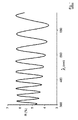
被覆された基板の第1の例には、ハードコーティングで被覆されたPETフィルムが含まれる。ハードコーティングは、アクリレート系コーティング、より特に、95重量%のペンタエリトリトールアクリレート多官能性モノマーの混合物、2重量%の添加剤および3重量%のUV硬化開始剤を含む。コーティングの厚さは、1.5〜3μmの間の範囲である。ハードコーティングは、510で1.48の屈折率を有する。PETフィルムは、厚さが23μmであり、510nmで1.65の屈折率を有する。 A first example of a coated substrate includes a PET film coated with a hard coating. The hard coating comprises an acrylate-based coating, more particularly a mixture of 95% by weight pentaerythritol acrylate multifunctional monomer, 2% by weight additive and 3% by weight UV curing initiator. The thickness of the coating ranges between 1.5 and 3 μm. The hard coating has a refractive index of 510 and 1.48. The PET film is 23 μm thick and has a refractive index of 1.65 at 510 nm.
この被覆された基板の反射スペクトルを図1に示す。図1の反射パターンは、可視域において顕著なフリンジ(fringes)を示す。 The reflection spectrum of this coated substrate is shown in FIG. The reflection pattern of FIG. 1 shows significant fringes in the visible range.
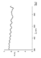
第2の例には、本発明によるハードコーティング層で被覆された基板が含まれる。ハードコーティングは、第1の例で述べたような、1.5〜3μmの間の範囲の厚さを有するアクリレート系コーティングを含む。基板は、厚さが23μmの、510nmで1.65の屈折率を有するPETフィルムを含む。ハードコーティングは、ZrO2ナノ粒子をさらに含む。ZrO2ナノ粒子の濃度は、基板とハードコーティングの間の屈折率の差が適合するように選択される。 A second example includes a substrate coated with a hard coating layer according to the present invention. The hard coating comprises an acrylate-based coating having a thickness in the range between 1.5 and 3 μm, as described in the first example. The substrate comprises a PET film having a thickness of 23 μm and a refractive index of 510 nm at 510 nm. The hard coating further comprises ZrO 2 nanoparticles. The concentration of ZrO 2 nanoparticles is selected such that the refractive index difference between the substrate and the hard coating is matched.
この被覆された基板の反射スペクトルを図2に示す。図2と比較して、可視域のフリンジはあまりはっきりせず、その結果、被覆された基板は真珠光沢を示さない。 The reflection spectrum of this coated substrate is shown in FIG. Compared to FIG. 2, the visible fringes are less pronounced, so that the coated substrate does not show iridescence.
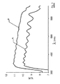
第3の例には、ウィンドウフィルムを備えたガラス基板が含まれる。ウィンドウフィルムは、PET基板およびZrO2粒子を含むハードコーティングを含む。ウィンドウフィルムは接着剤を用いてガラス基板に積層される。PET基板の厚さは23μmであり、ガラス基板は3mmの透明ガラスである。ハードコーティングは、第1の例で述べたような、アクリレート系コーティングを含む。 A third example includes a glass substrate with a window film. The window film includes a hard coating comprising a PET substrate and ZrO 2 particles. The window film is laminated on the glass substrate using an adhesive. The thickness of the PET substrate is 23 μm, and the glass substrate is 3 mm transparent glass. The hard coating includes an acrylate-based coating as described in the first example.
各々異なる濃度のZrO2粒子を有する、3種類の異なる実施形態のウィンドウフィルムが検討される。
第1の実施形態Aは、ZrO2粒子を加えないハードコーティングを含む。
第2の実施形態Bは、低い体積分率のZrO2粒子を有するハードコーティングを含む。
第3の実施形態Cは、PET基板とハードコーティングの屈折率の差を適合させる体積分率のZrO2粒子を有するハードコーティングを含む。
Three different embodiments of window films are considered, each having a different concentration of ZrO 2 particles.
The first embodiment A includes a hard coating without the addition of ZrO 2 particles.
The second embodiment B includes a hard coating with low volume fraction ZrO 2 particles.
The third embodiment C includes a hard coating having a volume fraction of ZrO 2 particles to match the refractive index difference between the PET substrate and the hard coating.
3種類の異なる実施形態のウィンドウフィルムを備えたガラスの反射スペクトルを図3に示す。図3から、スペクトルのフリンジは、PET基板とハードコーティングの屈折率の差が小さくなるように、ハードコーティング中のナノ粒子の濃度を増加させることにより減少すると結論づけることができる。 The reflection spectrum of the glass with the window film of three different embodiments is shown in FIG. From FIG. 3, it can be concluded that the spectral fringes decrease with increasing concentration of nanoparticles in the hard coating so that the difference in refractive index between the PET substrate and the hard coating is reduced.
Claims (21)
Applications Claiming Priority (3)
| Application Number | Priority Date | Filing Date | Title |
|---|---|---|---|
| EP07103056 | 2007-02-26 | ||
| EP07103056.3 | 2007-02-26 | ||
| PCT/EP2008/052152 WO2008104502A1 (en) | 2007-02-26 | 2008-02-21 | A layered structure comprising nanoparticles |
Publications (2)
| Publication Number | Publication Date |
|---|---|
| JP2010519084A true JP2010519084A (en) | 2010-06-03 |
| JP5453113B2 JP5453113B2 (en) | 2014-03-26 |
Family
ID=38261520
Family Applications (1)
| Application Number | Title | Priority Date | Filing Date |
|---|---|---|---|
| JP2009550717A Expired - Fee Related JP5453113B2 (en) | 2007-02-26 | 2008-02-21 | Layered structure containing nanoparticles |
Country Status (6)
| Country | Link |
|---|---|
| US (1) | US20090305013A1 (en) |
| EP (1) | EP2125941B1 (en) |
| JP (1) | JP5453113B2 (en) |
| CN (1) | CN101611080B (en) |
| ES (1) | ES2424189T3 (en) |
| WO (1) | WO2008104502A1 (en) |
Families Citing this family (7)
| Publication number | Priority date | Publication date | Assignee | Title |
|---|---|---|---|---|
| CN102127326B (en) * | 2010-12-28 | 2012-10-31 | 中国科学院上海硅酸盐研究所 | A kind of vanadium dioxide-based composite coating liquid and composite thin film and its preparation method and application |
| WO2014001404A2 (en) * | 2012-06-26 | 2014-01-03 | Nikon Corporation | Liquid polymerizable composition comprising mineral nanoparticles and its use to manufacture an optical article |
| CN103640302B (en) * | 2013-11-26 | 2016-05-18 | 上海紫东薄膜材料股份有限公司 | A kind of 3 layer co-extruding biaxial stretched functional polyester membrane structures |
| CN103640299B (en) * | 2013-11-26 | 2016-05-18 | 上海紫东薄膜材料股份有限公司 | A kind of co-extruding biaxial stretched functional polyester intelligent light modulation film and preparation method thereof |
| US20150175837A1 (en) * | 2013-12-23 | 2015-06-25 | Saint-Gobain Performance Plastics Corporation | Coating materials and low haze heat rejection composites |
| KR20180127461A (en) * | 2016-03-30 | 2018-11-28 | 피피지 코팅스 (텐진) 컴퍼니 리미티드 | Light diffusive reflective coating |
| CN107384231A (en) * | 2017-06-07 | 2017-11-24 | 常州诺澜复合材料有限公司 | A kind of preparation method of nano ceramics heat insulating membrane |
Citations (3)
| Publication number | Priority date | Publication date | Assignee | Title |
|---|---|---|---|---|
| JP2005096298A (en) * | 2003-09-25 | 2005-04-14 | Dainippon Printing Co Ltd | Optical film and optical display device comprising this optical film |
| JP2005215283A (en) * | 2004-01-29 | 2005-08-11 | Toppan Printing Co Ltd | Antistatic hard coat film and display medium |
| JP2006306980A (en) * | 2005-04-27 | 2006-11-09 | Mitsui Chemicals Inc | High refractive index resin composition for coating |
Family Cites Families (21)
| Publication number | Priority date | Publication date | Assignee | Title |
|---|---|---|---|---|
| CA2148115A1 (en) * | 1992-10-29 | 1994-05-11 | Walter J. Schrenk | Formable reflective multilayer body |
| US6498683B2 (en) * | 1999-11-22 | 2002-12-24 | 3M Innovative Properties Company | Multilayer optical bodies |
| TW415888B (en) * | 1998-02-17 | 2000-12-21 | Nippon Kayaku Kk | Transparent sheet or film |
| US6379774B1 (en) * | 1998-05-21 | 2002-04-30 | Teijin Limited | Composite polyester film and magnetic recording medium |
| DE19823732A1 (en) * | 1998-05-27 | 1999-12-02 | Inst Neue Mat Gemein Gmbh | Process for the production of optical multilayer systems |
| US6329058B1 (en) * | 1998-07-30 | 2001-12-11 | 3M Innovative Properties Company | Nanosize metal oxide particles for producing transparent metal oxide colloids and ceramers |
| US5956175A (en) * | 1998-07-31 | 1999-09-21 | Msc Specialty Films Inc | Solar control window film |
| JP4609962B2 (en) * | 2000-02-02 | 2011-01-12 | 日東電工株式会社 | Optical film |
| WO2001088889A1 (en) * | 2000-05-18 | 2001-11-22 | Bridgestone Corporation | Display panel, and electromagnetic shielding light transmitting window material manufacturing method |
| EP2420539A1 (en) * | 2001-10-25 | 2012-02-22 | Panasonic Electric Works Co., Ltd | Composite thin film holding substrate, transparent conductive film holding substrate, and surface light emitting body |
| KR100932873B1 (en) * | 2001-12-10 | 2009-12-21 | 데이진 듀폰 필름 가부시키가이샤 | Optical Adhesive Polyester Film |
| CN1646613A (en) * | 2002-02-19 | 2005-07-27 | 光子-X有限公司 | Polymer nanocomposites for optical applications |
| CN1204170C (en) * | 2002-08-08 | 2005-06-01 | 吉林大学 | Preparation method of nano particles with high refractive index and polymer nano composite film material |
| US7094461B2 (en) * | 2002-12-31 | 2006-08-22 | 3M Innovative Properties Company | P-polarizer with large z-axis refractive index difference |
| CN100439429C (en) * | 2003-03-25 | 2008-12-03 | 帝人杜邦菲林日本株式会社 | Antistatic Laminated Polyester Film |
| US6842288B1 (en) * | 2003-10-30 | 2005-01-11 | 3M Innovative Properties Company | Multilayer optical adhesives and articles |
| US7119140B2 (en) * | 2004-07-22 | 2006-10-10 | Ronald Basham | Transparent films, compositions, and method of manufacture thereof |
| US20070004813A1 (en) * | 2004-09-16 | 2007-01-04 | Eastman Chemical Company | Compositions for the preparation of void-containing articles |
| US7491441B2 (en) * | 2004-12-30 | 2009-02-17 | 3M Innovative Properties Company | High refractive index, durable hard coats |
| US20060255486A1 (en) * | 2005-05-10 | 2006-11-16 | Benson Olester Jr | Method of manufacturing composite optical body containing inorganic fibers |
| US20070292679A1 (en) * | 2006-06-14 | 2007-12-20 | 3M Innovative Properties Company | Optical article having an antistatic fluorochemical surface layer |
-
2008
- 2008-02-21 WO PCT/EP2008/052152 patent/WO2008104502A1/en not_active Ceased
- 2008-02-21 CN CN2008800050412A patent/CN101611080B/en not_active Expired - Fee Related
- 2008-02-21 EP EP08717020.5A patent/EP2125941B1/en not_active Not-in-force
- 2008-02-21 US US12/523,376 patent/US20090305013A1/en not_active Abandoned
- 2008-02-21 ES ES08717020T patent/ES2424189T3/en active Active
- 2008-02-21 JP JP2009550717A patent/JP5453113B2/en not_active Expired - Fee Related
Patent Citations (3)
| Publication number | Priority date | Publication date | Assignee | Title |
|---|---|---|---|---|
| JP2005096298A (en) * | 2003-09-25 | 2005-04-14 | Dainippon Printing Co Ltd | Optical film and optical display device comprising this optical film |
| JP2005215283A (en) * | 2004-01-29 | 2005-08-11 | Toppan Printing Co Ltd | Antistatic hard coat film and display medium |
| JP2006306980A (en) * | 2005-04-27 | 2006-11-09 | Mitsui Chemicals Inc | High refractive index resin composition for coating |
Also Published As
| Publication number | Publication date |
|---|---|
| ES2424189T3 (en) | 2013-09-27 |
| EP2125941B1 (en) | 2013-05-01 |
| WO2008104502A1 (en) | 2008-09-04 |
| CN101611080B (en) | 2011-12-28 |
| US20090305013A1 (en) | 2009-12-10 |
| CN101611080A (en) | 2009-12-23 |
| JP5453113B2 (en) | 2014-03-26 |
| EP2125941A1 (en) | 2009-12-02 |
Similar Documents
| Publication | Publication Date | Title |
|---|---|---|
| JP5453113B2 (en) | Layered structure containing nanoparticles | |
| JP6553897B2 (en) | Transparent thermal insulation member and method of manufacturing the same | |
| CN102034565B (en) | transparent conductive film | |
| TWI460742B (en) | Transparent conductive film | |
| US9778402B2 (en) | Light reflective film and light reflector produced using the same | |
| TWI530839B (en) | Sided transparent conductive film and touch panel | |
| EA031346B1 (en) | Transparent layered element | |
| WO2014010562A1 (en) | Infrared-shielding film | |
| JPWO2018074527A1 (en) | Transparent thermal insulation member | |
| CN104185802A (en) | Optical film | |
| JP4858269B2 (en) | Heat shield glass | |
| JP2017053967A (en) | Transparent thermal insulation member and method for producing the same | |
| JP2017191305A (en) | Optical body, window material, and roll curtain | |
| TWI332088B (en) | Anti-glare film | |
| WO2019065009A1 (en) | Optical body and window material | |
| JP4285059B2 (en) | Transparent conductive material and touch panel | |
| JP5865412B2 (en) | Infrared shielding film for windows | |
| JP2015150851A (en) | Method for producing functional film | |
| JP6326780B2 (en) | Window pasting film | |
| EP3362283A1 (en) | Seasonal solar control composite | |
| JP2013169714A (en) | Infrared suppressing article | |
| JP2016118632A (en) | Method for manufacturing optical control film | |
| JP6783348B2 (en) | Transparent heat shield and heat insulating member and its manufacturing method | |
| WO2017175588A1 (en) | Optical body, window material, and roll curtain | |
| JP2019056873A (en) | Optical body and window material |
Legal Events
| Date | Code | Title | Description |
|---|---|---|---|
| A621 | Written request for application examination |
Free format text: JAPANESE INTERMEDIATE CODE: A621 Effective date: 20110208 |
|
| A977 | Report on retrieval |
Free format text: JAPANESE INTERMEDIATE CODE: A971007 Effective date: 20120809 |
|
| A131 | Notification of reasons for refusal |
Free format text: JAPANESE INTERMEDIATE CODE: A131 Effective date: 20121016 |
|
| A601 | Written request for extension of time |
Free format text: JAPANESE INTERMEDIATE CODE: A601 Effective date: 20130116 |
|
| A711 | Notification of change in applicant |
Free format text: JAPANESE INTERMEDIATE CODE: A711 Effective date: 20130116 |
|
| A521 | Request for written amendment filed |
Free format text: JAPANESE INTERMEDIATE CODE: A523 Effective date: 20130307 |
|
| A521 | Request for written amendment filed |
Free format text: JAPANESE INTERMEDIATE CODE: A523 Effective date: 20130308 |
|
| A602 | Written permission of extension of time |
Free format text: JAPANESE INTERMEDIATE CODE: A602 Effective date: 20130405 |
|
| TRDD | Decision of grant or rejection written | ||
| A01 | Written decision to grant a patent or to grant a registration (utility model) |
Free format text: JAPANESE INTERMEDIATE CODE: A01 Effective date: 20131203 |
|
| A61 | First payment of annual fees (during grant procedure) |
Free format text: JAPANESE INTERMEDIATE CODE: A61 Effective date: 20140106 |
|
| R150 | Certificate of patent or registration of utility model |
Ref document number: 5453113 Country of ref document: JP Free format text: JAPANESE INTERMEDIATE CODE: R150 Free format text: JAPANESE INTERMEDIATE CODE: R150 |
|
| R250 | Receipt of annual fees |
Free format text: JAPANESE INTERMEDIATE CODE: R250 |
|
| R250 | Receipt of annual fees |
Free format text: JAPANESE INTERMEDIATE CODE: R250 |
|
| R250 | Receipt of annual fees |
Free format text: JAPANESE INTERMEDIATE CODE: R250 |
|
| LAPS | Cancellation because of no payment of annual fees |