JP2010514595A - Plastic fan with improved weld ring weld line strength - Google Patents
Plastic fan with improved weld ring weld line strength Download PDFInfo
- Publication number
- JP2010514595A JP2010514595A JP2009544279A JP2009544279A JP2010514595A JP 2010514595 A JP2010514595 A JP 2010514595A JP 2009544279 A JP2009544279 A JP 2009544279A JP 2009544279 A JP2009544279 A JP 2009544279A JP 2010514595 A JP2010514595 A JP 2010514595A
- Authority
- JP
- Japan
- Prior art keywords
- fan
- ring
- mold
- outer ring
- fan blades
- Prior art date
- Legal status (The legal status is an assumption and is not a legal conclusion. Google has not performed a legal analysis and makes no representation as to the accuracy of the status listed.)
- Pending
Links
Images


Classifications
-
- F—MECHANICAL ENGINEERING; LIGHTING; HEATING; WEAPONS; BLASTING
- F01—MACHINES OR ENGINES IN GENERAL; ENGINE PLANTS IN GENERAL; STEAM ENGINES
- F01P—COOLING OF MACHINES OR ENGINES IN GENERAL; COOLING OF INTERNAL-COMBUSTION ENGINES
- F01P5/00—Pumping cooling-air or liquid coolants
- F01P5/02—Pumping cooling-air; Arrangements of cooling-air pumps, e.g. fans or blowers
-
- B—PERFORMING OPERATIONS; TRANSPORTING
- B29—WORKING OF PLASTICS; WORKING OF SUBSTANCES IN A PLASTIC STATE IN GENERAL
- B29C—SHAPING OR JOINING OF PLASTICS; SHAPING OF MATERIAL IN A PLASTIC STATE, NOT OTHERWISE PROVIDED FOR; AFTER-TREATMENT OF THE SHAPED PRODUCTS, e.g. REPAIRING
- B29C33/00—Moulds or cores; Details thereof or accessories therefor
- B29C33/38—Moulds or cores; Details thereof or accessories therefor characterised by the material or the manufacturing process
- B29C33/3835—Designing moulds, e.g. using CAD-CAM
-
- B—PERFORMING OPERATIONS; TRANSPORTING
- B29—WORKING OF PLASTICS; WORKING OF SUBSTANCES IN A PLASTIC STATE IN GENERAL
- B29B—PREPARATION OR PRETREATMENT OF THE MATERIAL TO BE SHAPED; MAKING GRANULES OR PREFORMS; RECOVERY OF PLASTICS OR OTHER CONSTITUENTS OF WASTE MATERIAL CONTAINING PLASTICS
- B29B11/00—Making preforms
- B29B11/06—Making preforms by moulding the material
- B29B11/08—Injection moulding
-
- B—PERFORMING OPERATIONS; TRANSPORTING
- B29—WORKING OF PLASTICS; WORKING OF SUBSTANCES IN A PLASTIC STATE IN GENERAL
- B29C—SHAPING OR JOINING OF PLASTICS; SHAPING OF MATERIAL IN A PLASTIC STATE, NOT OTHERWISE PROVIDED FOR; AFTER-TREATMENT OF THE SHAPED PRODUCTS, e.g. REPAIRING
- B29C45/00—Injection moulding, i.e. forcing the required volume of moulding material through a nozzle into a closed mould; Apparatus therefor
- B29C45/0025—Preventing defects on the moulded article, e.g. weld lines, shrinkage marks
-
- B—PERFORMING OPERATIONS; TRANSPORTING
- B29—WORKING OF PLASTICS; WORKING OF SUBSTANCES IN A PLASTIC STATE IN GENERAL
- B29C—SHAPING OR JOINING OF PLASTICS; SHAPING OF MATERIAL IN A PLASTIC STATE, NOT OTHERWISE PROVIDED FOR; AFTER-TREATMENT OF THE SHAPED PRODUCTS, e.g. REPAIRING
- B29C45/00—Injection moulding, i.e. forcing the required volume of moulding material through a nozzle into a closed mould; Apparatus therefor
- B29C45/17—Component parts, details or accessories; Auxiliary operations
- B29C45/76—Measuring, controlling or regulating
-
- F—MECHANICAL ENGINEERING; LIGHTING; HEATING; WEAPONS; BLASTING
- F04—POSITIVE - DISPLACEMENT MACHINES FOR LIQUIDS; PUMPS FOR LIQUIDS OR ELASTIC FLUIDS
- F04D—NON-POSITIVE-DISPLACEMENT PUMPS
- F04D29/00—Details, component parts, or accessories
- F04D29/02—Selection of particular materials
- F04D29/023—Selection of particular materials especially adapted for elastic fluid pumps
-
- F—MECHANICAL ENGINEERING; LIGHTING; HEATING; WEAPONS; BLASTING
- F04—POSITIVE - DISPLACEMENT MACHINES FOR LIQUIDS; PUMPS FOR LIQUIDS OR ELASTIC FLUIDS
- F04D—NON-POSITIVE-DISPLACEMENT PUMPS
- F04D29/00—Details, component parts, or accessories
- F04D29/26—Rotors specially for elastic fluids
- F04D29/32—Rotors specially for elastic fluids for axial flow pumps
- F04D29/325—Rotors specially for elastic fluids for axial flow pumps for axial flow fans
- F04D29/326—Rotors specially for elastic fluids for axial flow pumps for axial flow fans comprising a rotating shroud
-
- B—PERFORMING OPERATIONS; TRANSPORTING
- B29—WORKING OF PLASTICS; WORKING OF SUBSTANCES IN A PLASTIC STATE IN GENERAL
- B29L—INDEXING SCHEME ASSOCIATED WITH SUBCLASS B29C, RELATING TO PARTICULAR ARTICLES
- B29L2031/00—Other particular articles
- B29L2031/08—Blades for rotors, stators, fans, turbines or the like, e.g. screw propellers
-
- F—MECHANICAL ENGINEERING; LIGHTING; HEATING; WEAPONS; BLASTING
- F05—INDEXING SCHEMES RELATING TO ENGINES OR PUMPS IN VARIOUS SUBCLASSES OF CLASSES F01-F04
- F05D—INDEXING SCHEME FOR ASPECTS RELATING TO NON-POSITIVE-DISPLACEMENT MACHINES OR ENGINES, GAS-TURBINES OR JET-PROPULSION PLANTS
- F05D2300/00—Materials; Properties thereof
- F05D2300/40—Organic materials
- F05D2300/43—Synthetic polymers, e.g. plastics; Rubber
-
- Y—GENERAL TAGGING OF NEW TECHNOLOGICAL DEVELOPMENTS; GENERAL TAGGING OF CROSS-SECTIONAL TECHNOLOGIES SPANNING OVER SEVERAL SECTIONS OF THE IPC; TECHNICAL SUBJECTS COVERED BY FORMER USPC CROSS-REFERENCE ART COLLECTIONS [XRACs] AND DIGESTS
- Y10—TECHNICAL SUBJECTS COVERED BY FORMER USPC
- Y10S—TECHNICAL SUBJECTS COVERED BY FORMER USPC CROSS-REFERENCE ART COLLECTIONS [XRACs] AND DIGESTS
- Y10S415/00—Rotary kinetic fluid motors or pumps
- Y10S415/915—Pump or portion thereof by casting or molding
Landscapes
- Engineering & Computer Science (AREA)
- Mechanical Engineering (AREA)
- General Engineering & Computer Science (AREA)
- Manufacturing & Machinery (AREA)
- Chemical & Material Sciences (AREA)
- Combustion & Propulsion (AREA)
- Structures Of Non-Positive Displacement Pumps (AREA)
- Moulds For Moulding Plastics Or The Like (AREA)
- Injection Moulding Of Plastics Or The Like (AREA)
Abstract
射出成形リングファンの実施形態及びその作製方法。本方法は、射出成形プロセス中に材料フローに対し、外側リングにおいて反対方向に流れる材料の主要な部分が好ましくは互いを通り越して流れ、渦巻く関係で混じり合い、及び/又は互いにある角度で衝突するように影響を及ぼす。この結果、フローフロントのより良好な材料の混合又は融合がもたらされる。一実施形態において、外側リングの厚さは、隣接するファンブレード間の異なる部分において変化する。 Embodiment of injection-molded ring fan and manufacturing method thereof. The method is such that, during the injection molding process, the major parts of the material flowing in opposite directions in the outer ring preferably flow past each other, mix in a swirling relationship and / or collide at an angle with each other during the injection molding process. To affect. This results in better material mixing or coalescence of the flow front. In one embodiment, the thickness of the outer ring varies in different portions between adjacent fan blades.
Description
関連出願の相互参照
本願は、2004年4月26日に出願された米国特許出願第10/831,789号明細書の一部継続出願である。
This application is a continuation-in-part of US application Ser. No. 10 / 831,789, filed Apr. 26, 2004.
本発明は、概してファン駆動システムに関し、及びより具体的にはファンリングのウエルドライン強度が向上したプラスチックファンに関する。 The present invention relates generally to fan drive systems, and more specifically to a plastic fan with improved weld line weld line strength.
本発明は、工業用エンジン又は自動車エンジンによって駆動され、且つその冷却に使用されるファンなどの冷却ファンに関する。より詳細には、本発明のある態様はリングファンに関し、一方で他の特徴はファンブレード設計に関する。 The present invention relates to a cooling fan such as a fan driven by an industrial engine or an automobile engine and used for cooling the engine. More particularly, certain aspects of the invention relate to ring fans, while other features relate to fan blade designs.
ほとんどの工業用エンジン及び自動車エンジン用途では、エンジン駆動冷却ファンを利用して冷媒ラジエータに通す空気を取り入れる。通常、ファンは、エンジンクランク軸と接続されたベルト駆動機構を介して駆動される。 In most industrial and automotive engine applications, an engine driven cooling fan is utilized to take in air that is passed through a refrigerant radiator. Usually, the fan is driven via a belt drive mechanism connected to the engine crankshaft.
典型的な冷却ファンは、中心ハブプレートに取り付けられた複数のブレードを含む。ハブプレートは、例えば、ベルト駆動機構との回転式接続を提供するように構成され得る。ファンブレードのサイズ及び数は、特定の用途に対する冷却要件によって決まる。例えば、小型自動車用ファンは、直径がわずか9インチの4枚のブレードしか要求されないこともある。より大きな用途では、より多くのブレードが要求される。ある典型的な大型自動車用途では、ファン設計に9枚のブレードが含まれ、それらのブレードは外径が704mmである。 A typical cooling fan includes a plurality of blades attached to a central hub plate. The hub plate can be configured, for example, to provide a rotational connection with a belt drive mechanism. The size and number of fan blades depends on the cooling requirements for a particular application. For example, a small car fan may require only four blades with a diameter of only 9 inches. For larger applications, more blades are required. In one typical heavy vehicle application, the fan design includes nine blades that have an outer diameter of 704 mm.
ブレードの数及び直径に加え、特定のファンの冷却能力はまた、ファンがその動作速度で生成できる気流量によっても影響される。この気流量は、特定のブレード幾何形状、例えばブレード面積及び曲率又は外形、並びにファンの回転速度に依存する。 In addition to the number and diameter of blades, the cooling capacity of a particular fan is also affected by the airflow that the fan can generate at its operating speed. This air flow rate depends on the specific blade geometry, such as blade area and curvature or profile, and the rotational speed of the fan.
冷却ファン寸法及び気流容量が増加するに従い、ファン、及び特にブレードが被る負荷もまた増加する。加えて、回転速度が高くなり、ファンを通じた気流が増加すると、ブレードのピッチのずれ(de−pitching)及び深刻な騒音問題につながり得る。こうした問題にある程度対処するため、特定の冷却ファン設計は、ファンの円周を囲むようにリングを組み込んでいる。具体的には、ブレード先端部がリングに装着され、このリングがブレード先端部に対し安定性を提供する。リングはまた、特にリングがリングの円周に従うU字型シュラウドと組み合わされるとき、ブレード先端部に発生する渦流を低減するのにも役立つ。 As the cooling fan size and airflow capacity increase, the load experienced by the fan and especially the blades also increases. In addition, higher rotational speeds and increased airflow through the fan can lead to blade pitch de-pitching and severe noise problems. In order to address these issues to some extent, certain cooling fan designs incorporate rings around the fan circumference. Specifically, the blade tip is attached to a ring, which provides stability to the blade tip. The ring also helps to reduce vortices generated at the blade tip, especially when the ring is combined with a U-shaped shroud that follows the circumference of the ring.
従って、リングファン設計は、従来の支持体のない冷却ファン構成が直面する構造上の課題のいくつかを排除する。しかしながら、リングファンによって強度の増加及び振動特性の改善が提供されることで、こうしたファンについての公称動作条件が高まり、リングファン性能の限界をさらに押し上げてきた。そのうえ、円周方向のリングの慣性質量によりブレード−リング接触面に加わる求心力が増加する。従って、従来の冷却ファン設計と同様、リングファンに対し、それが破損するまで加えることのできる力の大きさには限界がある。射出成形によって形成されるプラスチック又は繊維強化プラスチック成形リングファンについては、典型的には応力に起因して、ウエルドライン又はニットラインに沿って破損が生じる。このウエルドライン又はニットラインは、溶融ポリマー材料の2つの対向するフローフロントが、成形プロセス中に互いに実質的に180度の角度で「真正面から」衝突する場合に形成される。 Thus, the ring fan design eliminates some of the structural challenges faced by conventional supportless cooling fan configurations. However, the provision of increased strength and improved vibration characteristics by ring fans has increased the nominal operating conditions for these fans, further pushing the limits of ring fan performance. In addition, the centripetal force applied to the blade-ring contact surface is increased by the inertial mass of the circumferential ring. Thus, as with conventional cooling fan designs, there is a limit to the amount of force that can be applied to a ring fan until it breaks. For plastic or fiber reinforced plastic molded ring fans formed by injection molding, breakage occurs along the weld line or knit line, typically due to stress. This weld line or knit line is formed when two opposing flow fronts of molten polymer material impinge "from the front" at a substantially 180 degree angle on each other during the molding process.
結果的に、リングファンの冷却気流能力を向上させると同時に、リングファンの強度を増加させる方法の必要性が再び生じている。この必要性は、大型の工業用エンジン及び自動車エンジンについて高まる冷却要件に応えるようファンの動作回転速度が増加するに従い、特に強まっている。 As a result, there is a renewed need for a method that increases the ring fan's strength while simultaneously improving the cooling fan's cooling airflow capability. This need is particularly acute as the operating speed of the fan increases to meet the increasing cooling requirements for large industrial and automotive engines.
本発明は、ポリマー製又は繊維強化ポリマー製リングタイプのファン、特に射出成形プロセスを用いて形成されたファンの強度を増加させるための方法に関する。 The present invention relates to a method for increasing the strength of a polymer or fiber reinforced polymer ring type fan, in particular a fan formed using an injection molding process.
本発明の目的は、ウエルドライン又はニットラインの位置を応力の低い位置に、又はニットラインと対照的な、新しく生じるメルドラインに沿った向きに動かすことである。メルドラインは、対向する溶融材料のフローフロントが合流し、互いに対し180度以外の角度で−すなわち互いと「真正面から」ではなく−互いに衝突する場合に形成される。好ましくは、フローフロントは互いを部分的に越えて滑り込み、及び/又は渦を巻くようにして混ざり得る。目的はまた、メルドラインに沿ったガラス繊維による補強を向上させることである。本発明は、この結果を実現するためのいくつかの実施形態を提案する。 It is an object of the present invention to move the position of the weld line or knit line to a low stress position or to a direction along the newly created melt line as opposed to the knit line. A meldline is formed when the flow fronts of opposing molten materials meet and collide with each other at an angle other than 180 degrees—that is, not “in front of each other” —with each other. Preferably, the flow fronts may mix by sliding and / or swirling partially beyond each other. The aim is also to improve the reinforcement with glass fibers along the meld line. The present invention proposes several embodiments to achieve this result.
一実施形態において、ファンリングのうち2つの隣接するファンブレード間にあり、且つ先述のウエルドライン箇所の近傍に位置する可能性のある部分が厚くされ、従って溶融原材料がその範囲で通り越えるように流れるか、又は渦巻くことが可能となり、この位置で直接衝突する材料が最小量のメルドラインが形成される。こうした実施形態の1つにおいて、2つの隣接するファンブレード間のファンリングは、ブレードの一方に隣接する断面積が他方に隣接する断面積より大きく、且つより大きい面積と小さい面積とが多様な角度をもつ形で交差し、それにより2つのフローが少なくとも部分的に互いの側端に沿って通り越え、混じり合う、又は渦巻くタイプの相互作用を生じ易くなる。 In one embodiment, the portion of the fan ring that is between two adjacent fan blades and that may be located in the vicinity of the aforementioned weld line location is thickened so that the molten raw material passes through that range. It can flow or swirl, forming a meldline with minimal amount of material that impinges directly at this location. In one such embodiment, the fan ring between two adjacent fan blades has a cross-sectional area adjacent to one of the blades that is larger than a cross-sectional area adjacent to the other, and a large and small area with various angles. Crossing, making it easier for two flows to pass at least partially along side edges of each other, intermingling or swirling.
別の実施形態において、材料のフローに影響を及ぼし、直接的な衝突又は180°のニットラインの形成を妨げるために、1つ又は複数のスピルオーバー型リザーバが、成形中に隣接するファンブレード間の外側ファンリングに対し、可能であればメルドラインの近傍の位置に追加される。リザーバは成形ファンの付加物を形成し、また、溶融物から不純物をパージして除去もし得る。こうした不純物としては、限定はされないが、閉じ込められた空気、発生したガス、細かいデブリ、及び離型剤が挙げられ、これらはフローフロントに集まる傾向を有する。こうした不純物は、ポリマーの接着性及びガラス繊維/樹脂界面の接着強度に作用し得る。付加物はファンリングの内側表面上か、又は外側表面上のいずれにあってもよく、車両冷却システムの一部としてファンが組み立てられる前に取り外される。 In another embodiment, one or more spill-over reservoirs are placed between adjacent fan blades during molding to affect material flow and prevent direct impact or 180 ° knit line formation. For the outer fan ring, it is added at a position near the meld line if possible. The reservoir forms an adjunct to the molding fan and can also purge and remove impurities from the melt. Such impurities include, but are not limited to, trapped air, generated gas, fine debris, and release agents, which tend to collect on the flow front. Such impurities can affect polymer adhesion and glass fiber / resin interface adhesion strength. The appendage can be either on the inside surface of the fan ring or on the outside surface and is removed before the fan is assembled as part of the vehicle cooling system.
本発明それ自体は、付随する利点と共に、添付の図面を併せて考慮しながら、以下の詳細な説明を参照することによって最も良く理解されるであろう。 The invention itself, together with attendant advantages, will be best understood by reference to the following detailed description, taken in conjunction with the accompanying drawings.
本発明の原理の理解を促進する目的から、ここで図面に例示される実施形態が参照され、及びそれらを説明するために特定の用語が用いられる。それでもなお、それによって本発明の範囲を限定することは意図されないことは理解されるであろう。本発明は、例示される装置及び説明される方法における任意の変更及びさらなる改良、並びに本発明が関係する当業者に通常想起されるであろう本発明の原理のさらなる適用を含む。 For the purposes of promoting an understanding of the principles of the invention, reference will now be made to the embodiments illustrated in the drawings and specific language will be used to describe the same. It will nevertheless be understood that no limitation of the scope of the invention is thereby intended. The present invention includes any changes and further improvements in the apparatus illustrated and the methods described, as well as further applications of the principles of the invention that would normally occur to those skilled in the art to which the invention pertains.
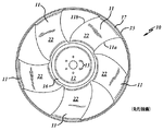
ここで図1及び2を参照すると、先行技術に係る典型的なリングファン10が、中心ハブプレート12に取り付けられた複数のブレード11を備える。図1に示されるとおり、ハブプレート12は、ファンを公知の設計のファン駆動アセンブリに取り付けるように構成された取付けボルトリング13を備え得る。ファン10はさらに、ファンブレード11の各々のブレード先端部17に固定された外側リング15と、ブレード11の各々の根元部19に固定された内側リング16とを備えてもよい。内側リング16、外側リング15及びブレード11は好ましくは高強度の成形可能ポリマー材料から形成され、この材料は好ましくは、従来の公知のプロセスで金属製ハブプレート12の周囲に射出成形される。使用される典型的なプラスチックとしては、ポリアミド(ナイロン6及び商標名Zytel(登録商標)Nytelのナイロンなど)又はポリプロピレンが挙げられる。こうしたプラスチックは典型的には、約15〜50%、及びより好ましくは15〜30%の繊維強化材で補強される。繊維強化材は典型的にはガラス短繊維の形態だが、ガラス長繊維もまた用いられ得る。
1 and 2, a
ブレード11の各々は、リングファン10の有効な吸入口にある前面22を備える。同様に、各ブレードはリングファンの裏側に反対側の後面25(図2を参照)を備える。好ましい実施形態において、5枚のブレード11が設けられてもよく、各々はブレード根元部19からブレード先端部17までほぼ均一な厚さを有する。代替的実施形態において、ブレード11の各々は、ブレードの前縁端11aから後縁端11bにかけて厚さが変わり得る。各ブレード11は好ましくは、リングファン10がその規格回転速度の動作範囲内、且つそのシステム制約上の目標範囲内で動作するとき最大気流を提供するように構成されたエアフォイル型形状に従う。
Each of the
図2を参照すると、ファン10の外側リング15が、概してファンの吐出面に配置された張出しリム28を備えることが分かる。張出しリム28は半径方向外側に張り出した表面29を画定し、これはブレード11の各々の先端部17から漸次離れる曲率に従う。ファン10は、ファンブレードの前縁端11aに吸入側端を、及び後縁端11bに反対側の吐出側端を画定する。外側リング15の張出しリム28は、ファン10の吐出側端に配置される。
Referring to FIG. 2, it can be seen that the
図面には、5枚のブレード及びブレードの長さに沿った均一な曲線を備えるファンが示されるが、ブレードの枚数及びブレードの正確な曲率は本発明の一部ではない。本発明に従う成形プラスチックファンは、任意の断面形状及びブレードの長さに沿った任意の構造曲率を備える任意の枚数のブレードを有し得る。また、図面には張出しリムを備えたファンが示されるが、必ずしもファンが本発明に従う張出しリムを有する必要はない。 Although the drawing shows a fan with five blades and a uniform curve along the length of the blade, the number of blades and the exact curvature of the blades are not part of the present invention. A molded plastic fan according to the present invention may have any number of blades with any cross-sectional shape and any structural curvature along the length of the blade. Also, although the drawings show a fan with an overhang rim, the fan need not necessarily have an overhang rim according to the present invention.
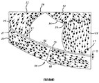
図3は、先行技術に係るリングファン10の外側リング15の拡大した強調図を示し、これは、従来のプラスチック射出成形プロセスで外側リング15を形成するために用いられる溶けた(すなわち溶融された)プラスチック材料のフローフロント50、60を示す。かかるプロセスでは、典型的には2つの半体で形成される金型が射出成形機に位置決めされる。その金型には、最終的に成形される部品の形状をしたキャビティが形成されている。金型が閉じられた後、溶融プラスチック材料がゲート(オリフィスとしても知られる)を通じて金型キャビティの中に注入される。
FIG. 3 shows an enlarged highlight of the
ファンの成形では、プラスチック材料は典型的には、ハブリング16に位置決めされたゲートを通じて注入される。ゲートはブレード11の各々の根元部19に位置決めされる。注入されたプラスチック材料は金型キャビティのブレード部分全体にわたり半径方向外側に同時に流れる。外側リングにおいては、プラスチックは各ブレードから別々に流れ、金型キャビティのリング部分に沿って両方向に流れる。
In fan molding, plastic material is typically injected through a gate positioned in the
上記のとおりポリアミドで形成されるプラスチックファン10については、溶融ポリアミド(すなわち原材料)はゲートを通じ、摂氏約218〜226度(華氏424〜439度)で約500トン〜1,500トンの圧力の能力のプレス機に注入される。金型内に含まれるゲートは、概して直径が約1〜4mm(0.039インチ〜約0.157インチ)の範囲である。
For the
金型キャビティがプラスチック材料で完全に充填されると、典型的には金型にはさらにプラスチックが送り込まれ、プラスチックの冷却に伴う任意の収縮が補償される。プラスチックが冷却され十分に硬化すると、金型が開けられ成形されたファン10が取り出される。
When the mold cavity is completely filled with plastic material, typically, the mold is further pumped with plastic to compensate for any shrinkage associated with plastic cooling. When the plastic is cooled and sufficiently cured, the mold is opened and the molded
原材料が金型キャビティの中に注入されると、溶融原材料は最小抵抗の経路に沿って流れる(図3の矢印によって示されるとおり)。このようにして原材料の一部がハブリング16を形成する。示されるとおり、溶融プラスチック原材料の一部はまた、それぞれのゲートからブレード11を通り、根元部19から先端部17まで流れて外側リングキャビティに入ることにより、外側リング15も形成する。フローフロント50、60は外側リング15内部において、2枚の隣接するブレード先端部から、各ブレードの先端部からほぼ等距離にある中央範囲に向かって進む。2つのフローフロント50、60は典型的には、外側リング15の内周23及び外周27とほぼ垂直な非常に平面的な領域55に沿って互いに合流し、「真正面から」直接衝突する。平面領域55は、この中央範囲内における外側リング15の内周23及び外周27の接線と垂直に延在する。外側リング15の厚さ「T」はリングの長さ及び幅に沿って一定である。フローフロント50、60が合流して固化すると、ブレード11のそれぞれの隣接する各対の間にある外側リング15にニットライン75が生じる。当業者に周知のとおり、ニットライン75は典型的には、外側リング15のうち遠心力で誘起された曲げ応力に対して最も脆弱な部分に相当する。
As the raw material is injected into the mold cavity, the molten raw material flows along the path of minimum resistance (as indicated by the arrows in FIG. 3). In this way, part of the raw material forms the
ニットライン75の形状には部品の幾何形状が影響し得るが、一般にニットラインはかなり直線状であり、外側リング15に沿って軸方向に、隣接するブレード先端部17のほぼ中間を外側リング15の内周23及び外周27の双方を画定する接線と垂直に延在する。
Although the shape of the knit
ニットライン75がなぜ外側リング15のうち最も脆弱な部分に相当するのかについては、多くの理由がある。ニットライン75は閉じ込められた空気及び発生したガスを含み、これらが構造体にボイドを生じさせることによって外側リング15の強度に影響し得る。そのうえ、成形プロセスにおいて導入される溶融材料に含まれる離型剤、細かいデブリ及び/又は他の不純物はニットライン75に沿って集まる傾向を有し、結果として形成された母型構造の不連続性につながり、それによって構造が脆弱となり得る。こうした同じ材料がポリマーの接着性及びポリマー材料とガラス繊維強化材料との間の接着性の双方に影響し、それによりニットライン75の強度がさらに低下し得る。さらに、フローフロントが衝突するため、ガラス繊維に含まれる繊維は熱可塑性材料に入り込んで混じり合うことが容易にはできず、従ってニットライン75に沿った補強に悪影響が及ぶ。
There are many reasons why the
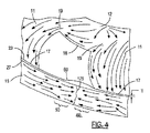
図4は、リングファン10のこうした様々なウエルドラインにおける強度を向上させるための一実施形態を例示する。図4では、プラスチック原材料のフローフロント50、60の方向が、外側リング15の厚さをブレード間の部分80に沿って変化させることによって変えられている。一実施形態において、この厚みは外側リングの内表面23上の膨隆部により形成される。膨隆部は一方のブレード先端部から他方へと厚さが均一且つ連続的に増加して、隣接するブレード間のほぼ等距離にある伸張した隆起又は突起を形成し得る。或いは膨隆部は、2枚の隣接するブレード間のほぼ中間に本質的に「スピードバンプ」のように形成されてもよい。本発明に従い他のサイズ及び形状の膨隆部が設けられてもよい。フローフロント50及び60が膨隆部の範囲に前進すると、非直線的なメルドライン175が形成されると考えられ、これによりメルドライン、ひいては成形ファン製品の強度が向上し得る。
FIG. 4 illustrates one embodiment for improving the strength of these various weld lines of the
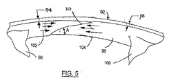
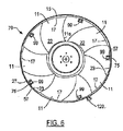
本発明の別の実施形態が図5に図示され、これはファンリング92の内側表面90の図である。ファンの周囲を囲む厚さが一定のリングを、リング92のうちあるファンブレード96と隣り合うか、又はその近傍の一部分94の断面のサイズ及び面積が、リングのうち隣接するブレード100と隣り合うか、又はその近傍の部分98の断面のサイズ及び面積より大きくなる(又は厚くなる)ように変化させる。これと同じ構造が、ファンリングの円周にわたり各ブレード対の間で繰り返され、それによりファンアセンブリの質量について均等に平衡が保たれる。従って、注入された溶融プラスチックがブレードに沿って半径方向外側に流れ、各ブレード先端部において2つのフローに分かれると、ある方向に流れるプラスチック部分が、反対方向に流れるプラスチック部分より大きいサイズ及び容積の範囲に入り込む。各フローは最小抵抗の経路(より大きい容積)を辿ろうとするため、ブレード間の範囲において隣接するブレードからの逆向きにやって来るフローとのパターンに従った流れが始まる。
Another embodiment of the present invention is illustrated in FIG. 5, which is a view of the
部分94の、ファンリングの残りの部分に対する厚さの増加比は、好ましくは約1.25:1〜2:1の範囲である。必要に応じて当業者は厚みの増加及び増加比を変えることにより、最も強度の高いメルドラインを確実にすることができる。
The ratio of thickness increase of
図5に示される実施形態では、2つの対向するフローフロント102及び104はまた、互いにある角度で合流し、フローフロントの各々の少なくとも一部分が好ましくは他方の側端沿いに滑り込むか、又は越えて進む。フローフロントの前縁端における材料はまた、互いに回転し合うか、又は渦を巻き、それにより2つのフローフロントが混ざり合って一体に同化する。図3に示されるような平面領域55又は図4に示されるような非直線状メルドライン175に沿って合流及び固化するのではなく、図5の実施形態の2つのフローフロントは、さらに激しく互い違いになって粗いメルドラインをもたらし得る。
In the embodiment shown in FIG. 5, the two opposing
図5に示される実施形態で指摘されるとおり、ブレードの各対の間の厚くされたリング部分94により、2つのフローフロント102及び104の少なくとも一部分は、新しく形成されるメルドライン110において互いに角度Aに従い合流する。角度Aは好ましくは30°〜60°であるが、2つのフローフロントを大幅に混ぜ合わせる任意の許容可能な角度であってもよい。メルドライン110は直線状か、又は湾曲していてもよく、湾曲している場合、凸形状、凹形状、又は任意の形状を有し得る。
As pointed out in the embodiment shown in FIG. 5, due to the thickened
代替的実施形態において、ファンリングのうち隣接するファンブレード間の部分の厚さは、別の様式で変化し得る。図5に示されるような部分94などの、ファンブレードの一部分の厚さが、図5を見ている観察者の方に向く方向、すなわちファンリングから半径方向内側に拡張し得る。加えて、図5に示されるような部分98などの、ファンブレードのうち隣接するファンブレードの近傍の、又はそれと隣り合う別の部分の厚さが、観察者から遠ざかる方向、すなわちファンリングから半径方向外側に拡張し得る。この構造は、各ファンブレードからの材料フローの各部分が互いの側端沿いに滑り込むか、又は越えて進み、2つのフローフロントの混ざり合いが生じることが確実となるよう支援し得る。ここでも、この同じ構造がファンリングの周囲にわたって繰り返されることにより、ファンの均等な平衡が保たれなければならない。
In alternative embodiments, the thickness of the portion of the fan ring between adjacent fan blades may vary in other ways. The thickness of a portion of the fan blade, such as
図6は、リングファン70の外側リング15の強度を向上させるための別の方法を例示する。複数のスピルオーバー型の付加物99が、プラスチック射出成形プロセス中に形成される。付加物は、外側リング15上の隣接するブレード11の各対の間に形成される。図6では、付加物99は外側リング15の内表面又は内周23に沿って連結されて示される。各ブレード先端部17(図3にあるような)からのフローフロントの材料は、図3に示される領域55などの平面領域に沿って合流及び固化するのとは対照的に、スピルオーバー付加物99へと流れ込む。このようにして、新しく形成されるメルドラインは外側リング15では最小限に抑えられ(除去されるか、又は低減され)、その代わりに付加物99に形成され得る。フロー材料が冷却され、成形ファンが金型から取り出された後、付加物99は捻り取るか、又は切り取るなどして容易に取り外される。
FIG. 6 illustrates another method for improving the strength of the
スピルオーバー付加物99の使用はまた、金型内部に閉じ込められたガスのパージにも役立つ。付加物は、離型時の残渣及び他の不純物、例えば酸化した残渣又はデブリなどを成形プロセス中に回収し得る場所を提供する。こうした不純物の除去は、外側リング内部にあるポリマーの接着性及びポリマー材料とガラス繊維強化材料との間の接着性の双方を向上させる働きをする。
The use of the
付加物99は図6では、隣接するファンブレード間の中央に、外側リング15の内周23に沿って位置するものとして示されるが、代替的実施形態を利用することができる。付加物99をブレードの隣接する対の間の任意の位置に置くことで、新しいメルドラインを種々の位置に形成することが可能である。また、各ファンブレード対の間に2つ以上のスピルオーバー付加物を提供することも可能である。
The
付加物はさらに、破線で示される付加物120によって表されるように、外側リングの外周27に沿って形成され得る。他の実施形態において、ある付加物が内周23上に形成され、別の付加物が外周27上に形成され、且つ付加物の各々が、ブレード先端部17の隣接する各対の間に任意に位置し得る。ブレード先端部17のある隣接する対の間に形成される付加物の数が、ブレード先端部17の別の隣接する対の間に形成される付加物の数と異なり得ることもまた可能であり得るが、その場合には、付加物は全てきれいに、且つ均等に取り外されなければならず、さもなければファンが不均衡な状態のままとなり得る。
An appendage may further be formed along the
図4〜6に関連する上記のとおりの実施形態において、ファン駆動システムで使用されるファンの外側リングの強度を向上させるための方法論は、図7に示されるとおりのフロー図に従い達成され得る。第一に、ステップ200において、所望のリングファンのサイズ及び形状に対応する内空を有するファン用のプロトタイプ金型が作製される。このプロトタイプ金型では、外側リングの厚さは一定に保たれる。次に、ステップ210において、所定量の溶融原材料が、複数のゲートの各々を通じて前記内空の中に所望の温度及び圧力で同時に導入される。ステップ220において、原材料がプロトタイプ金型内で冷却されると、プロトタイプファンが形成される。
In the embodiment as described above in connection with FIGS. 4-6, a methodology for improving the strength of the outer ring of a fan used in a fan drive system may be achieved according to a flow diagram as shown in FIG. First, in
ステップ230において、外側リングに沿った、複数のファンブレードの隣接する各対の間のニットラインの位置が決定される。上記のとおり、ニットラインは、リングファンの外側リングのうち隣接するファンブレード間にある最も脆弱な部分に相当し、前記所定量の溶融プラスチック材料の一部分の第1のフローフロントが前記所定量の溶融プラスチック材料の第2の部分の第2のフローフロントと衝突する位置に形成される。均一な厚さの外側リング(すなわち均一な断面サイズ及び形状)では、理想的な成形条件下で、フローフロントは互いに直接衝突して、図3に示されるタイプの直線状のニットラインを形成する。
At
次に、ステップ240において、前記プロトタイプ金型の内空が付形し直され、それによって成形プロセスでリングファンが形成され、このリングファンにおいては一方のフローフロントの溶融プラスチック材料のフローの一部分が、第2のフローフロントからの溶融プラスチック材料の一部分と異なる形で衝突する。図4ではこのステップは、領域80などにおいて、外側リング15の厚さをその長さ及び幅の各部分に沿って所望のとおり増加させることにより達成される。図5ではこのステップは、領域94などにおいて、外側リング92の厚さをその長さ及び幅の各部分に沿って所望のとおり増加させることにより達成される。図6ではこのステップは、外側リング15に沿って1つ又は複数のスピルオーバー付加物を設けることにより達成される。さらに別の実施形態において、外側リングの厚さを上記に指摘されるとおり変化させてもよく、且つ外側リングに沿ったスピルオーバー付加物もまた設けられてもよい。
Next, in
ステップ250では、所定量の溶融プラスチック材料が、複数のゲートの各々を通じて、付形し直されたプロトタイプの前記内空の中に、所望の温度及び圧力で同時に導入される。
In
ステップ260では、付形し直されたプロトタイプファンの強度が、外側リング全体にわたり一定の厚さを有するプロトタイプファンの強度と比較される。
In
最終的には、必要であれば、ステップ270においてプロトタイプ型が付形し直され、ステップ240〜200が繰り返されることにより、所望の最適強度の外側リングが実現される。
Eventually, if necessary, the prototype mold is reshaped at
図3に示されるリングファンの外側リング15にはニットライン75が形成されるものとして示されるが、リングファンのうちフローフロントが交わる他の範囲にさらなるニットライン(図示せず)が形成され得ることが認識される。例えば、溶融プラスチック材料のフローはまた、原材料がゲートを通じて同時に注入されるとき、内側リング16の範囲内のゲート間においても交わる。従って、リングファン強度を向上させるための本方法が、リングファンの他の部分に組み込まれてもよい。例えば、同様の方法を用いてハブリング16の強度を向上させることもできる。内側リングの厚さをハブリングの周囲にわたり均一に変化させてもよく、及び/又はスピルオーバー付加物が設けられてもよい。
Although the
このように本発明は、成形リングファンの強度を向上させるための特有の方策を説明する。本発明により提供されるさらなるファンリング強度は、大型の工業用エンジン及び自動車エンジンについての高い冷却要件に応えてファンの動作回転速度が増加するに従い、特に重大となる。 Thus, the present invention describes a unique strategy for improving the strength of a molded ring fan. The additional fan ring strength provided by the present invention becomes particularly significant as the operating speed of the fan increases in response to high cooling requirements for large industrial and automotive engines.
さらに、本明細書に記載される実施形態及び方法は、成形プロセス中に溶融原材料のフローが交わるあらゆる成形可能なプラスチック部品の形成にも同様に適用できる。 In addition, the embodiments and methods described herein are equally applicable to the formation of any moldable plastic part where the flow of molten raw material meets during the molding process.
本発明は1つ又は複数の実施形態に関連して説明されているが、説明されている特定の機構及び技術は単に本発明の原理の例示に過ぎず、説明されている方法及び装置に対し、添付の特許請求の範囲によって定義されるとおりの本発明の趣旨及び範囲から逸脱することなく、多くの変更が加えられ得ることは理解されたい。 Although the invention has been described in connection with one or more embodiments, the specific mechanisms and techniques described are merely illustrative of the principles of the present invention and are directed to the methods and apparatus described. It should be understood that many modifications may be made without departing from the spirit and scope of the invention as defined by the appended claims.
Claims (10)
内空を有するプロトタイプ金型を形成するステップであって、前記内空が前記ファンのサイズ及び形状に対応し、前記外側リングの厚さが一定であり、前記金型が前記内側リングの周囲に位置する複数のゲートを有し、前記複数のゲートのうち1つが、前記複数のファンブレードのうちの1枚に対応する位置において前記内側リングと密接に連結される、ステップと、
前記プロトタイプ金型に対し、所定量の溶融プラスチック材料を、前記複数のゲートの各々を通じて前記内空の中に所望の温度及び圧力で同時に導入するステップと、
前記所定量の溶融プラスチック材料を前記プロトタイプ金型の内部で冷却してプロトタイプファンを形成するステップと、
前記プロトタイプファンの内部で前記外側リングに沿って前記複数のファンブレードのそれぞれの隣接する各対の間にあるウエルドラインの位置を決定するステップであって、前記ウエルドラインが前記プロトタイプファンの前記外側リングのうち前記複数のファンブレードのそれぞれの隣接する各対の間にある最も脆弱な部分に相当し、前記外側リングの前記最も脆弱な部分が、前記所定量の溶融原材料の一部分の第1のフローフロントが前記所定量の溶融プラスチック材料の第2の部分の第2のフローフロントと衝突する位置に形成され、前記第1のフローフロントが、前記外側リングに沿って前記複数のファンブレードの前記隣接する対の一方から前記複数のファンブレードの前記隣接する対の他方へと、実質的に第1の方向に流れ、及び前記第2のフローフロントが、前記外側リングに沿って前記複数のファンブレードの前記隣接する対の前記他方から前記複数のファンブレードの前記隣接する対の前記一方へと、実質的に第2の方向に流れる、ステップと、
前記内空を、前記プロトタイプ金型の前記複数のファンブレードの前記それぞれの隣接する対のうち少なくとも1つの対の間で付形し直して金型を形成するステップと、
前記金型に対し、第2の所定量の溶融プラスチック材料を、前記複数のゲートの各々を通じて前記内空の中に所望の温度及び圧力で同時に導入するステップであって、前記第2の所定量の溶融プラスチック材料の第3の部分が、前記複数のファンブレードの前記それぞれの隣接する対の前記一方と前記複数のファンブレードの前記それぞれの隣接する対の前記他方との間に、実質的に第3の方向で流れ、及び前記第2の所定量の溶融プラスチック材料の第4の部分が、前記複数のファンブレードの前記それぞれの隣接する対の前記他方と前記のファンブレードの前記それぞれの隣接する対の前記一方との間に、実質的に第4の方向で流れ、前記第3の部分が前記第4の部分と、前記外側リングにおいて前記複数のファンブレードの前記隣接する対の間で、前記第3の方向と前記第4の方向との間の角度として定義される角度Aで衝突する、ステップと、
前記所定量の溶融原材料を前記金型内で冷却して前記ファンを形成するステップと、
前記ファンを前記金型から取り出すステップと、
を含む、方法。 A fan for use in a fan drive system for improving the outer ring strength of a fan having a plurality of fan blades connected between an outer ring and an inner ring, comprising:
Forming a prototype mold having an inner space, wherein the inner space corresponds to the size and shape of the fan, the outer ring has a constant thickness, and the mold is disposed around the inner ring. A plurality of gates positioned, wherein one of the plurality of gates is intimately connected to the inner ring at a position corresponding to one of the plurality of fan blades;
Simultaneously introducing a predetermined amount of molten plastic material into the interior of the prototype mold through each of the plurality of gates into the interior at a desired temperature and pressure;
Cooling the predetermined amount of molten plastic material within the prototype mold to form a prototype fan;
Determining a position of a weld line between each adjacent pair of the plurality of fan blades along the outer ring within the prototype fan, wherein the weld line is the outer side of the prototype fan. Corresponding to the most vulnerable portion of each of the plurality of fan blades between each adjacent pair of rings, the most vulnerable portion of the outer ring being a first of a portion of the predetermined amount of molten raw material. A flow front is formed at a position where it collides with a second flow front of a second portion of the predetermined amount of molten plastic material, the first flow front extending along the outer ring with the plurality of fan blades. Flowing from one of the adjacent pairs to the other of the adjacent pairs of the plurality of fan blades in a substantially first direction; And the second flow front is substantially second along the outer ring from the other of the adjacent pairs of the plurality of fan blades to the one of the adjacent pairs of the plurality of fan blades. Steps, flowing in the direction of
Reshaping the inner space between at least one of the adjacent pairs of the plurality of fan blades of the prototype mold to form a mold;
Introducing a second predetermined amount of molten plastic material into the mold at a desired temperature and pressure simultaneously through each of the plurality of gates to the mold, wherein the second predetermined amount A third portion of the molten plastic material substantially between the one of the respective adjacent pairs of the plurality of fan blades and the other of the respective adjacent pairs of the plurality of fan blades A fourth portion of the second predetermined amount of molten plastic material flowing in a third direction and the other of the adjacent pairs of the plurality of fan blades and the respective adjacent of the fan blades; The third portion flows in a substantially fourth direction between the one of the plurality of fan blades, and the third portion is adjacent to the fourth portion and the plurality of fan blades in the outer ring. Between pairs, it impinges at an angle A, which is defined as the angle between the third direction and the fourth direction, and a step,
Cooling the predetermined amount of molten raw material in the mold to form the fan;
Removing the fan from the mold;
Including a method.
前記金型の前記内空を、前記外側リングの強度が最適となるまで付形し直すステップと、
をさらに含む、請求項1に記載の方法。 Comparing the strength of the outer ring of the mold with the strength of the outer ring of the prototype mold;
Re-shaping the inner space of the mold until the strength of the outer ring is optimal;
The method of claim 1, further comprising:
前記成形リングファンのサイズ及び形状に対応するキャビティを有する金型を形成するステップであって、前記金型が、前記複数のファンブレードに対応する前記ハブリングの周囲に位置する複数のゲートを有し、及び前記金型が、前記複数のファンブレードの隣接する各対の間の少なくとも一部分に増加するファンリング厚さを有する、ステップと、
所定量の溶融プラスチック材料を前記複数のゲートの各々を通じて所望の温度及び圧力で同時に導入することにより、前記金型キャビティを充填するステップと、
前記所定量の溶融プラスチック材料を前記金型内で冷却して前記リングファンを形成するステップと、
前記リングファンを前記金型から取り出すステップと、
を含む、方法。 A ring fan for use in a fan drive system, the ring fan having a plurality of fan blades connected between an outer ring and a hub ring,
Forming a mold having a cavity corresponding to the size and shape of the molded ring fan, the mold having a plurality of gates located around the hub ring corresponding to the plurality of fan blades; And the mold has a fan ring thickness that increases to at least a portion between each adjacent pair of the plurality of fan blades;
Filling the mold cavity by simultaneously introducing a predetermined amount of molten plastic material through each of the plurality of gates at a desired temperature and pressure;
Cooling the predetermined amount of molten plastic material in the mold to form the ring fan;
Removing the ring fan from the mold;
Including a method.
中心ハブ部材と、
前記ハブ部材から放射状に延在する複数のファンブレードと、
前記ファンブレードの各々の外側端部に取り付けられた外側リングと、
を備え、前記外側リングが、前記ファンブレードの1つに隣接する第1の厚さの第1の部分を有し、且つ隣接するファンブレードに隣接する第2の厚さの第2の部分を有し、
前記第1の厚さが前記第2の厚さより大きい、プラスチック成形リングファン。 A plastic molded ring fan,
A central hub member;
A plurality of fan blades extending radially from the hub member;
An outer ring attached to the outer end of each of the fan blades;
The outer ring has a first portion of a first thickness adjacent to one of the fan blades, and a second portion of a second thickness adjacent to the adjacent fan blade. Have
A plastic molded ring fan, wherein the first thickness is greater than the second thickness.
Applications Claiming Priority (2)
| Application Number | Priority Date | Filing Date | Title |
|---|---|---|---|
| US11/617,696 US7789628B2 (en) | 2004-04-26 | 2006-12-28 | Plastic fans having improved fan ring weld line strength |
| PCT/US2007/088999 WO2008083255A1 (en) | 2006-12-28 | 2007-12-28 | Plastic fans having improved fan ring weld line strength |
Publications (1)
| Publication Number | Publication Date |
|---|---|
| JP2010514595A true JP2010514595A (en) | 2010-05-06 |
Family
ID=39591101
Family Applications (1)
| Application Number | Title | Priority Date | Filing Date |
|---|---|---|---|
| JP2009544279A Pending JP2010514595A (en) | 2006-12-28 | 2007-12-28 | Plastic fan with improved weld ring weld line strength |
Country Status (8)
| Country | Link |
|---|---|
| US (1) | US7789628B2 (en) |
| EP (1) | EP2097626A4 (en) |
| JP (1) | JP2010514595A (en) |
| KR (1) | KR20090094020A (en) |
| CN (3) | CN101548081B (en) |
| BR (1) | BRPI0719614A2 (en) |
| IN (1) | IN2009KN02405A (en) |
| WO (1) | WO2008083255A1 (en) |
Cited By (1)
| Publication number | Priority date | Publication date | Assignee | Title |
|---|---|---|---|---|
| WO2017164398A1 (en) * | 2016-03-24 | 2017-09-28 | Ntn株式会社 | Bearing holder made of resin and method for manufacturing same, and rolling bearing |
Families Citing this family (20)
| Publication number | Priority date | Publication date | Assignee | Title |
|---|---|---|---|---|
| US9903387B2 (en) | 2007-04-05 | 2018-02-27 | Borgwarner Inc. | Ring fan and shroud assembly |
| US20090155076A1 (en) * | 2007-12-18 | 2009-06-18 | Minebea Co., Ltd. | Shrouded Dual-Swept Fan Impeller |
| JP4969493B2 (en) * | 2008-02-28 | 2012-07-04 | 三菱重工業株式会社 | Plastic fan |
| FR2950660B1 (en) * | 2009-09-29 | 2017-08-25 | Valeo Systemes Thermiques | PROPELLER, MOTOR COOLING DEVICE COMPRISING SUCH A PROPELLER, METHOD AND MOLD FOR MANUFACTURING THE SAME |
| WO2011143064A2 (en) | 2010-05-10 | 2011-11-17 | Borgwarner Inc. | Fan with overmolded blades |
| JP5454400B2 (en) | 2010-07-15 | 2014-03-26 | 株式会社富士通ゼネラル | Propeller fan and manufacturing method thereof |
| ES2608791T3 (en) * | 2012-04-17 | 2017-04-17 | D.W. Plastics Nv | Injection molding process to form a bottle box, bottle box and corresponding apparatus to obtain said bottle box |
| CN203453120U (en) * | 2013-09-03 | 2014-02-26 | 讯凯国际股份有限公司 | Fan and fan impeller thereof |
| AT514828B1 (en) | 2013-09-24 | 2015-06-15 | Hoerbiger Kompressortech Hold | Method and mold for the production of sealing plates by injection molding as well as correspondingly produced sealing plates |
| TWD160897S (en) * | 2013-10-09 | 2014-06-01 | 訊凱國際股份有限公司 | Cooling fan (1) |
| TWD160896S (en) * | 2013-10-09 | 2014-06-01 | 訊凱國際股份有限公司 | Cooling fan (2) |
| RU2544898C1 (en) * | 2014-03-18 | 2015-03-20 | Федеральное государственное бюджетное образовательное учреждение высшего профессионального образования "Елецкий государственный университет им. И.А. Бунина" | Fan impeller |
| US20160208823A1 (en) * | 2015-01-19 | 2016-07-21 | Hamilton Sundstrand Corporation | Shrouded fan rotor |
| USD787037S1 (en) * | 2015-07-01 | 2017-05-16 | Dometic Sweden Ab | Fan |
| JP6825995B2 (en) * | 2017-06-02 | 2021-02-03 | 株式会社ブリヂストン | Manufacturing method for injection molding dies, resin members, and resin products |
| DE102017215570A1 (en) * | 2017-09-05 | 2019-03-07 | Robert Bosch Gmbh | Injection molding process for producing a fan with improved weld line strength |
| CN108799197B (en) * | 2018-05-31 | 2024-05-07 | 珠海格力精密模具有限公司 | Fan blade structure, air conditioner and method for detecting fan blade structure |
| DE102020210648A1 (en) * | 2020-08-21 | 2022-02-24 | Brose Fahrzeugteile SE & Co. Kommanditgesellschaft, Würzburg | Process for producing an injection molded part |
| DE102020127199A1 (en) * | 2020-10-15 | 2022-04-21 | Ebm-Papst Mulfingen Gmbh & Co. Kg | Method of manufacturing an impeller |
| US20240239458A1 (en) * | 2021-05-05 | 2024-07-18 | Albert Handtmann Elteka Gmbh & Co.Kg | Propeller for driving watercraft |
Citations (8)
| Publication number | Priority date | Publication date | Assignee | Title |
|---|---|---|---|---|
| JPS51117864U (en) * | 1975-03-19 | 1976-09-24 | ||
| JPH08224762A (en) * | 1994-12-20 | 1996-09-03 | Hitachi Ltd | Injection molding, manufacture thereof, and mold thereof |
| WO2001024986A1 (en) * | 1999-10-05 | 2001-04-12 | Conix Corporation | Injection molding techniques utilizing interlocking knit lines |
| JP2002307475A (en) * | 2001-04-12 | 2002-10-23 | Polyplastics Co | Cylindrical mold for injection-molding, molding method, and molding |
| JP2003094494A (en) * | 2001-09-25 | 2003-04-03 | Denso Corp | Fan and its molding method |
| JP2003145588A (en) * | 2001-11-19 | 2003-05-20 | Shin Etsu Chem Co Ltd | Injection mold and method for manufacturing injection- molded article using the same |
| JP2005313640A (en) * | 2004-04-26 | 2005-11-10 | Borgwarner Inc | Plastic fan having improved melting line intensity of retrofit fan ring |
| JP2006224461A (en) * | 2005-02-17 | 2006-08-31 | Nishikawa Kasei Co Ltd | Ring-shaped product made of resin and its injection molding method |
Family Cites Families (11)
| Publication number | Priority date | Publication date | Assignee | Title |
|---|---|---|---|---|
| US3201857A (en) * | 1963-03-21 | 1965-08-24 | Torrington Mfg Co | Method of making fan with slinger ring |
| US4358245A (en) * | 1980-09-18 | 1982-11-09 | Bolt Beranek And Newman Inc. | Low noise fan |
| US4569632A (en) * | 1983-11-08 | 1986-02-11 | Airflow Research And Manufacturing Corp. | Back-skewed fan |
| CA2104400C (en) * | 1990-12-14 | 2004-03-16 | Windiron Pty. Limited | Propeller with shrouding ring attached to blades |
| JP3666536B2 (en) * | 1997-05-19 | 2005-06-29 | 光洋精工株式会社 | Manufacturing method of cage made of synthetic resin |
| EP0945627B1 (en) * | 1998-03-23 | 2004-01-02 | SPAL S.r.l. | Axial flow fan |
| JP4122111B2 (en) * | 1998-08-07 | 2008-07-23 | 豊田合成株式会社 | Resin molded product having opening hole and method for producing the same |
| US6142733A (en) * | 1998-12-30 | 2000-11-07 | Valeo Thermique Moteur | Stator for fan |
| JP4029035B2 (en) * | 2000-11-08 | 2008-01-09 | ロバート ボッシュ エルエルシー | High efficiency and suitable axial flow fan |
| KR20040104974A (en) * | 2003-06-03 | 2004-12-14 | 삼성전자주식회사 | Turbofan and mold for manufacturing the same |
| US20060026699A1 (en) * | 2004-06-04 | 2006-02-02 | Largaespada David A | Methods and compositions for identification of genomic sequences |
-
2006
- 2006-12-28 US US11/617,696 patent/US7789628B2/en active Active
-
2007
- 2007-12-28 IN IN2405KON2009 patent/IN2009KN02405A/en unknown
- 2007-12-28 WO PCT/US2007/088999 patent/WO2008083255A1/en active Application Filing
- 2007-12-28 KR KR1020097013854A patent/KR20090094020A/en not_active Application Discontinuation
- 2007-12-28 CN CN2007800451305A patent/CN101548081B/en not_active Expired - Fee Related
- 2007-12-28 BR BRPI0719614-8A2A patent/BRPI0719614A2/en not_active IP Right Cessation
- 2007-12-28 EP EP07870009A patent/EP2097626A4/en not_active Withdrawn
- 2007-12-28 CN CN201110207822.3A patent/CN102287400B/en not_active Expired - Fee Related
- 2007-12-28 JP JP2009544279A patent/JP2010514595A/en active Pending
- 2007-12-28 CN CN201110405272.6A patent/CN102490307B/en not_active Expired - Fee Related
Patent Citations (8)
| Publication number | Priority date | Publication date | Assignee | Title |
|---|---|---|---|---|
| JPS51117864U (en) * | 1975-03-19 | 1976-09-24 | ||
| JPH08224762A (en) * | 1994-12-20 | 1996-09-03 | Hitachi Ltd | Injection molding, manufacture thereof, and mold thereof |
| WO2001024986A1 (en) * | 1999-10-05 | 2001-04-12 | Conix Corporation | Injection molding techniques utilizing interlocking knit lines |
| JP2002307475A (en) * | 2001-04-12 | 2002-10-23 | Polyplastics Co | Cylindrical mold for injection-molding, molding method, and molding |
| JP2003094494A (en) * | 2001-09-25 | 2003-04-03 | Denso Corp | Fan and its molding method |
| JP2003145588A (en) * | 2001-11-19 | 2003-05-20 | Shin Etsu Chem Co Ltd | Injection mold and method for manufacturing injection- molded article using the same |
| JP2005313640A (en) * | 2004-04-26 | 2005-11-10 | Borgwarner Inc | Plastic fan having improved melting line intensity of retrofit fan ring |
| JP2006224461A (en) * | 2005-02-17 | 2006-08-31 | Nishikawa Kasei Co Ltd | Ring-shaped product made of resin and its injection molding method |
Cited By (2)
| Publication number | Priority date | Publication date | Assignee | Title |
|---|---|---|---|---|
| WO2017164398A1 (en) * | 2016-03-24 | 2017-09-28 | Ntn株式会社 | Bearing holder made of resin and method for manufacturing same, and rolling bearing |
| JP2017172736A (en) * | 2016-03-24 | 2017-09-28 | Ntn株式会社 | Resin-made cage for bearing, manufacturing method of the same and rolling bearing |
Also Published As
| Publication number | Publication date |
|---|---|
| IN2009KN02405A (en) | 2015-08-07 |
| CN101548081A (en) | 2009-09-30 |
| CN102490307B (en) | 2015-05-13 |
| US20070104581A1 (en) | 2007-05-10 |
| KR20090094020A (en) | 2009-09-02 |
| CN101548081B (en) | 2012-05-16 |
| CN102287400A (en) | 2011-12-21 |
| CN102490307A (en) | 2012-06-13 |
| WO2008083255A1 (en) | 2008-07-10 |
| EP2097626A4 (en) | 2013-02-13 |
| CN102287400B (en) | 2015-02-04 |
| BRPI0719614A2 (en) | 2014-04-01 |
| US7789628B2 (en) | 2010-09-07 |
| EP2097626A1 (en) | 2009-09-09 |
Similar Documents
| Publication | Publication Date | Title |
|---|---|---|
| JP2010514595A (en) | Plastic fan with improved weld ring weld line strength | |
| EP1612023B1 (en) | Molded plastic fans having improved fan ring weld line strength | |
| CN107869483B (en) | Axial fan and outdoor unit using same | |
| JP4969493B2 (en) | Plastic fan | |
| EP3034884B1 (en) | Centrifugal fan assembly | |
| US9790954B2 (en) | Propeller, engine cooling device comprising such a propeller, and mould for producing said propeller | |
| JP2010526960A (en) | Collaborative blade and hub structure for cooling fans | |
| US7192253B2 (en) | Method for producing a fan wheel and fan wheel produced by this method | |
| US20110014052A1 (en) | Fan with structural support ring | |
| US20030231960A1 (en) | Fan blade assembly | |
| US11898569B2 (en) | Banded cooling fan band having knit-line strength improvement | |
| JPH06137298A (en) | Blade structure for fan | |
| CN221401010U (en) | Fan assembly and fan module | |
| US11959489B2 (en) | Banded cooling fan band having knit-line strength improvement | |
| US20230228279A1 (en) | Banded cooling fan band having knit-line strength improvement | |
| JP4950762B2 (en) | cooling fan | |
| KR20240081858A (en) | Axial flow fan | |
| KR20020086142A (en) | Turbo fan and manufacturing process thereof |
Legal Events
| Date | Code | Title | Description |
|---|---|---|---|
| A621 | Written request for application examination |
Free format text: JAPANESE INTERMEDIATE CODE: A621 Effective date: 20101210 |
|
| A521 | Written amendment |
Free format text: JAPANESE INTERMEDIATE CODE: A523 Effective date: 20110912 |
|
| A977 | Report on retrieval |
Free format text: JAPANESE INTERMEDIATE CODE: A971007 Effective date: 20120222 |
|
| A131 | Notification of reasons for refusal |
Free format text: JAPANESE INTERMEDIATE CODE: A131 Effective date: 20120228 |
|
| A601 | Written request for extension of time |
Free format text: JAPANESE INTERMEDIATE CODE: A601 Effective date: 20120524 |
|
| A602 | Written permission of extension of time |
Free format text: JAPANESE INTERMEDIATE CODE: A602 Effective date: 20120531 |
|
| A02 | Decision of refusal |
Free format text: JAPANESE INTERMEDIATE CODE: A02 Effective date: 20120927 |