JP6825995B2 - Manufacturing method for injection molding dies, resin members, and resin products - Google Patents

Manufacturing method for injection molding dies, resin members, and resin products Download PDF

Info

Publication number
JP6825995B2
JP6825995B2 JP2017110451A JP2017110451A JP6825995B2 JP 6825995 B2 JP6825995 B2 JP 6825995B2 JP 2017110451 A JP2017110451 A JP 2017110451A JP 2017110451 A JP2017110451 A JP 2017110451A JP 6825995 B2 JP6825995 B2 JP 6825995B2
Authority
JP
Japan
Prior art keywords
resin
cavity
center line
width center
main body
Prior art date
Legal status (The legal status is an assumption and is not a legal conclusion. Google has not performed a legal analysis and makes no representation as to the accuracy of the status listed.)
Active
Application number
JP2017110451A
Other languages
Japanese (ja)
Other versions
JP2018202730A (en
Inventor
俊輔 深津
俊輔 深津
田中 寛治
寛治 田中
陽一 西室
陽一 西室
Current Assignee (The listed assignees may be inaccurate. Google has not performed a legal analysis and makes no representation or warranty as to the accuracy of the list.)
Bridgestone Corp
Original Assignee
Bridgestone Corp
Priority date (The priority date is an assumption and is not a legal conclusion. Google has not performed a legal analysis and makes no representation as to the accuracy of the date listed.)
Filing date
Publication date
Application filed by Bridgestone Corp filed Critical Bridgestone Corp
Priority to JP2017110451A priority Critical patent/JP6825995B2/en
Priority to US16/618,224 priority patent/US11135753B2/en
Priority to PCT/JP2018/018567 priority patent/WO2018221184A1/en
Priority to EP18808929.6A priority patent/EP3632647A4/en
Priority to CN201880036661.6A priority patent/CN110709229B/en
Priority to TW107118637A priority patent/TWI691396B/en
Publication of JP2018202730A publication Critical patent/JP2018202730A/en
Application granted granted Critical
Publication of JP6825995B2 publication Critical patent/JP6825995B2/en
Active legal-status Critical Current
Anticipated expiration legal-status Critical

Links

Images

Classifications

    • BPERFORMING OPERATIONS; TRANSPORTING
    • B29WORKING OF PLASTICS; WORKING OF SUBSTANCES IN A PLASTIC STATE IN GENERAL
    • B29CSHAPING OR JOINING OF PLASTICS; SHAPING OF MATERIAL IN A PLASTIC STATE, NOT OTHERWISE PROVIDED FOR; AFTER-TREATMENT OF THE SHAPED PRODUCTS, e.g. REPAIRING
    • B29C45/00Injection moulding, i.e. forcing the required volume of moulding material through a nozzle into a closed mould; Apparatus therefor
    • B29C45/17Component parts, details or accessories; Auxiliary operations
    • B29C45/26Moulds
    • B29C45/37Mould cavity walls, i.e. the inner surface forming the mould cavity, e.g. linings
    • BPERFORMING OPERATIONS; TRANSPORTING
    • B29WORKING OF PLASTICS; WORKING OF SUBSTANCES IN A PLASTIC STATE IN GENERAL
    • B29CSHAPING OR JOINING OF PLASTICS; SHAPING OF MATERIAL IN A PLASTIC STATE, NOT OTHERWISE PROVIDED FOR; AFTER-TREATMENT OF THE SHAPED PRODUCTS, e.g. REPAIRING
    • B29C45/00Injection moulding, i.e. forcing the required volume of moulding material through a nozzle into a closed mould; Apparatus therefor
    • B29C45/0005Injection moulding, i.e. forcing the required volume of moulding material through a nozzle into a closed mould; Apparatus therefor using fibre reinforcements
    • BPERFORMING OPERATIONS; TRANSPORTING
    • B29WORKING OF PLASTICS; WORKING OF SUBSTANCES IN A PLASTIC STATE IN GENERAL
    • B29CSHAPING OR JOINING OF PLASTICS; SHAPING OF MATERIAL IN A PLASTIC STATE, NOT OTHERWISE PROVIDED FOR; AFTER-TREATMENT OF THE SHAPED PRODUCTS, e.g. REPAIRING
    • B29C45/00Injection moulding, i.e. forcing the required volume of moulding material through a nozzle into a closed mould; Apparatus therefor
    • B29C45/0025Preventing defects on the moulded article, e.g. weld lines, shrinkage marks
    • BPERFORMING OPERATIONS; TRANSPORTING
    • B29WORKING OF PLASTICS; WORKING OF SUBSTANCES IN A PLASTIC STATE IN GENERAL
    • B29CSHAPING OR JOINING OF PLASTICS; SHAPING OF MATERIAL IN A PLASTIC STATE, NOT OTHERWISE PROVIDED FOR; AFTER-TREATMENT OF THE SHAPED PRODUCTS, e.g. REPAIRING
    • B29C45/00Injection moulding, i.e. forcing the required volume of moulding material through a nozzle into a closed mould; Apparatus therefor
    • B29C45/17Component parts, details or accessories; Auxiliary operations
    • B29C45/72Heating or cooling
    • B29C45/73Heating or cooling of the mould
    • BPERFORMING OPERATIONS; TRANSPORTING
    • B29WORKING OF PLASTICS; WORKING OF SUBSTANCES IN A PLASTIC STATE IN GENERAL
    • B29CSHAPING OR JOINING OF PLASTICS; SHAPING OF MATERIAL IN A PLASTIC STATE, NOT OTHERWISE PROVIDED FOR; AFTER-TREATMENT OF THE SHAPED PRODUCTS, e.g. REPAIRING
    • B29C70/00Shaping composites, i.e. plastics material comprising reinforcements, fillers or preformed parts, e.g. inserts
    • B29C70/04Shaping composites, i.e. plastics material comprising reinforcements, fillers or preformed parts, e.g. inserts comprising reinforcements only, e.g. self-reinforcing plastics
    • B29C70/06Fibrous reinforcements only
    • B29C70/10Fibrous reinforcements only characterised by the structure of fibrous reinforcements, e.g. hollow fibres
    • B29C70/12Fibrous reinforcements only characterised by the structure of fibrous reinforcements, e.g. hollow fibres using fibres of short length, e.g. in the form of a mat
    • B29C70/14Fibrous reinforcements only characterised by the structure of fibrous reinforcements, e.g. hollow fibres using fibres of short length, e.g. in the form of a mat oriented
    • FMECHANICAL ENGINEERING; LIGHTING; HEATING; WEAPONS; BLASTING
    • F16ENGINEERING ELEMENTS AND UNITS; GENERAL MEASURES FOR PRODUCING AND MAINTAINING EFFECTIVE FUNCTIONING OF MACHINES OR INSTALLATIONS; THERMAL INSULATION IN GENERAL
    • F16BDEVICES FOR FASTENING OR SECURING CONSTRUCTIONAL ELEMENTS OR MACHINE PARTS TOGETHER, e.g. NAILS, BOLTS, CIRCLIPS, CLAMPS, CLIPS OR WEDGES; JOINTS OR JOINTING
    • F16B2/00Friction-grip releasable fastenings
    • F16B2/02Clamps, i.e. with gripping action effected by positive means other than the inherent resistance to deformation of the material of the fastening
    • F16B2/06Clamps, i.e. with gripping action effected by positive means other than the inherent resistance to deformation of the material of the fastening external, i.e. with contracting action
    • F16B2/065Clamps, i.e. with gripping action effected by positive means other than the inherent resistance to deformation of the material of the fastening external, i.e. with contracting action using screw-thread elements
    • FMECHANICAL ENGINEERING; LIGHTING; HEATING; WEAPONS; BLASTING
    • F16ENGINEERING ELEMENTS AND UNITS; GENERAL MEASURES FOR PRODUCING AND MAINTAINING EFFECTIVE FUNCTIONING OF MACHINES OR INSTALLATIONS; THERMAL INSULATION IN GENERAL
    • F16BDEVICES FOR FASTENING OR SECURING CONSTRUCTIONAL ELEMENTS OR MACHINE PARTS TOGETHER, e.g. NAILS, BOLTS, CIRCLIPS, CLAMPS, CLIPS OR WEDGES; JOINTS OR JOINTING
    • F16B7/00Connections of rods or tubes, e.g. of non-circular section, mutually, including resilient connections
    • BPERFORMING OPERATIONS; TRANSPORTING
    • B29WORKING OF PLASTICS; WORKING OF SUBSTANCES IN A PLASTIC STATE IN GENERAL
    • B29CSHAPING OR JOINING OF PLASTICS; SHAPING OF MATERIAL IN A PLASTIC STATE, NOT OTHERWISE PROVIDED FOR; AFTER-TREATMENT OF THE SHAPED PRODUCTS, e.g. REPAIRING
    • B29C45/00Injection moulding, i.e. forcing the required volume of moulding material through a nozzle into a closed mould; Apparatus therefor
    • B29C45/0025Preventing defects on the moulded article, e.g. weld lines, shrinkage marks
    • B29C2045/0027Gate or gate mark locations
    • BPERFORMING OPERATIONS; TRANSPORTING
    • B29WORKING OF PLASTICS; WORKING OF SUBSTANCES IN A PLASTIC STATE IN GENERAL
    • B29KINDEXING SCHEME ASSOCIATED WITH SUBCLASSES B29B, B29C OR B29D, RELATING TO MOULDING MATERIALS OR TO MATERIALS FOR MOULDS, REINFORCEMENTS, FILLERS OR PREFORMED PARTS, e.g. INSERTS
    • B29K2105/00Condition, form or state of moulded material or of the material to be shaped
    • B29K2105/06Condition, form or state of moulded material or of the material to be shaped containing reinforcements, fillers or inserts
    • B29K2105/12Condition, form or state of moulded material or of the material to be shaped containing reinforcements, fillers or inserts of short lengths, e.g. chopped filaments, staple fibres or bristles
    • B29K2105/14Condition, form or state of moulded material or of the material to be shaped containing reinforcements, fillers or inserts of short lengths, e.g. chopped filaments, staple fibres or bristles oriented
    • BPERFORMING OPERATIONS; TRANSPORTING
    • B29WORKING OF PLASTICS; WORKING OF SUBSTANCES IN A PLASTIC STATE IN GENERAL
    • B29KINDEXING SCHEME ASSOCIATED WITH SUBCLASSES B29B, B29C OR B29D, RELATING TO MOULDING MATERIALS OR TO MATERIALS FOR MOULDS, REINFORCEMENTS, FILLERS OR PREFORMED PARTS, e.g. INSERTS
    • B29K2105/00Condition, form or state of moulded material or of the material to be shaped
    • B29K2105/06Condition, form or state of moulded material or of the material to be shaped containing reinforcements, fillers or inserts
    • B29K2105/20Inserts

Description

この発明は、射出成形金型、樹脂部材、及び、樹脂製品の製造方法に関するものである。 The present invention relates to an injection molding die, a resin member, and a method for manufacturing a resin product.

射出成形金型のキャビティ内で溶融樹脂が合流してウェルド部が形成される場合、成形品におけるウェルド部の強度が他の部分よりも低くなる傾向がある。ウェルド部の強度を向上するために、従来より様々な試みが行われてきた(例えば、特許文献1)。 When the molten resin merges in the cavity of the injection molding die to form a weld portion, the strength of the weld portion in the molded product tends to be lower than that of other portions. Various attempts have been made conventionally to improve the strength of the weld portion (for example, Patent Document 1).

特開2002-240096号公報JP-A-2002-240096

しかしながら、従来の技術では、ウェルド部の強度を十分に向上できず、改善の余地があった。 However, with the conventional technique, the strength of the weld portion cannot be sufficiently improved, and there is room for improvement.

この発明は、上述した課題を解決するためのものであり、ウェルド部の強度を向上できる、射出成形金型、樹脂部材、及び、樹脂製品の製造方法を、提供することを目的とするものである。 The present invention is for solving the above-mentioned problems, and an object of the present invention is to provide a method for manufacturing an injection molding die, a resin member, and a resin product, which can improve the strength of a weld portion. is there.

本発明の射出成形金型は、ゲート及びキャビティを備え、強化繊維入りの溶融樹脂を前記ゲートから前記キャビティ内に射出することにより、前記キャビティ内でウェルド部が形成されるように構成された、射出成形金型において、前記キャビティに開口する樹脂溜まりを有しており、前記樹脂溜まりの前記キャビティへの開口端面に沿った第1断面において、前記キャビティの幅中心線の垂線に沿って測ったときの、前記樹脂溜まりの幅中心線と前記キャビティの幅中心線との間の距離が、前記キャビティの幅中心線に沿って、少なくとも一部分で変化する。
本発明の射出成形金型によれば、ウェルド部の強度を向上できる。
The injection molding die of the present invention includes a gate and a cavity, and is configured such that a weld portion is formed in the cavity by injecting a molten resin containing reinforcing fibers from the gate into the cavity. The injection-molded mold has a resin pool that opens in the cavity, and is measured along the perpendicular line of the width center line of the cavity in the first cross section of the resin pool along the opening end face of the cavity. When, the distance between the width center line of the resin pool and the width center line of the cavity changes at least in a part along the width center line of the cavity.
According to the injection molding die of the present invention, the strength of the weld portion can be improved.

本発明の射出成形金型においては、前記第1断面において、前記樹脂溜まりの幅中心線は、前記キャビティの幅中心線に対して、非直角に交差する方向に延びていると、好適である。
この構成によれば、ウェルド部の強度をさらに向上できる。
In the injection molding die of the present invention, it is preferable that the width center line of the resin pool extends in a direction not perpendicular to the width center line of the cavity in the first cross section. ..
According to this configuration, the strength of the weld portion can be further improved.

本発明の射出成形金型においては、前記第1断面において、前記樹脂溜まりの幅中心線は、前記キャビティの幅中心線に対して、非直角に交差すると、好適である。
この構成によれば、ウェルド部の強度をさらに向上できる。
In the injection molding die of the present invention, it is preferable that the width center line of the resin pool intersects the width center line of the cavity at a right angle in the first cross section.
According to this configuration, the strength of the weld portion can be further improved.

本発明の射出成形金型においては、前記キャビティは、円筒状部材を成形するように構成されており、前記樹脂溜まりは、前記円筒状部材の軸方向のいずれか一方側の端面を成形するためのキャビティ面に、開口しており、前記第1断面において、前記樹脂溜まりの幅中心線は、前記キャビティの中心軸線からの距離が、前記樹脂溜まりの幅中心線に沿って変化する部分を有すると、好適である。
この構成によれば、円筒状部材のウェルド部の強度を向上できる。
In the injection molding die of the present invention, the cavity is configured to form a cylindrical member, and the resin pool forms an end face of the cylindrical member on either one side in the axial direction. The width center line of the resin pool has a portion in which the distance from the center axis of the cavity changes along the width center line of the resin pool in the first cross section. Then, it is suitable.
According to this configuration, the strength of the weld portion of the cylindrical member can be improved.

本発明の射出成形金型においては、前記第1断面において、前記樹脂溜まりの幅中心線の一方側の端部は、前記樹脂溜まりの幅中心線の他方側の端部よりも、前記キャビティの中心軸線からの距離が長いと、好適である。
この構成によれば、円筒状部材のウェルド部の強度をさらに向上できる。
In the injection molding die of the present invention, in the first cross section, one end of the width center line of the resin pool is more of the cavity than the other end of the width center line of the resin pool. A long distance from the central axis is preferable.
According to this configuration, the strength of the weld portion of the cylindrical member can be further improved.

本発明の射出成形金型においては、前記キャビティは、前記円筒状部材の軸方向のいずれか一方側の内周面にめねじを成形するように構成されていてもよい。
この場合でも、円筒状部材のウェルド部の強度を十分に確保できる。
In the injection molding die of the present invention, the cavity may be configured to form a female screw on the inner peripheral surface of the cylindrical member on any one side in the axial direction.
Even in this case, the strength of the weld portion of the cylindrical member can be sufficiently ensured.

本発明の射出成形金型においては、前記樹脂溜まりは、前記円筒状部材の軸方向両側のうち、前記めねじが成形される側の端面を成形するためのキャビティ面に、開口していると、好適である。
この構成によれば、特に強度が要求されるめねじの周辺で、ウェルド部の強度を十分に確保できる。
In the injection molding die of the present invention, the resin pool is said to be open to the cavity surface for molding the end face of the cylindrical member on the side where the female screw is molded on both sides in the axial direction. , Suitable.
According to this configuration, sufficient strength of the weld portion can be secured around the female screw, which is particularly required to have strength.

本発明の射出成形金型においては、前記樹脂溜まりの前記キャビティへの開口端面の外縁は、非直角の対角を有する平行四辺形状に形成されていると、好適である。
この構成によれば、ウェルド部の強度をさらに向上できる。
In the injection molding die of the present invention, it is preferable that the outer edge of the opening end surface of the resin pool to the cavity is formed in a parallel quadrilateral shape having a non-right angle diagonal shape.
According to this configuration, the strength of the weld portion can be further improved.

本発明の樹脂部材は、強化繊維入りの樹脂から構成され、ウェルド部が形成されている、樹脂部材において、前記樹脂部材の本体部に連結された突起部を有しており、前記突起部の前記本体部への連結端面に沿った第1断面において、前記本体部の幅中心線の垂線に沿って測ったときの、前記突起部の幅中心線と前記本体部の幅中心線との間の距離が、前記本体部の幅中心線に沿って、少なくとも一部分で変化する。
本発明の樹脂部材によれば、ウェルド部の強度を向上できる。
The resin member of the present invention is a resin member composed of a resin containing reinforcing fibers and having a welded portion, and has a protrusion connected to the main body of the resin member. In the first cross section along the end surface connected to the main body, between the width center line of the protrusion and the width center line of the main body when measured along the perpendicular line of the width center line of the main body. The distance of the main body changes at least in a part along the width center line of the main body.
According to the resin member of the present invention, the strength of the weld portion can be improved.

本発明の樹脂部材においては、前記第1断面において、前記突起部の幅中心線は、前記本体部の幅中心線に対して、非直角に交差する方向に延びていると、好適である。
本発明の樹脂部材によれば、ウェルド部の強度をさらに向上できる。
In the resin member of the present invention, it is preferable that the width center line of the protrusion extends in a direction not perpendicular to the width center line of the main body in the first cross section.
According to the resin member of the present invention, the strength of the weld portion can be further improved.

本発明の樹脂部材においては、第1断面において、前記突起部の幅中心線は、前記本体部の幅中心線に対して、非直角に交差すると、好適である。
この構成によれば、ウェルド部の強度をさらに向上できる。
In the resin member of the present invention, it is preferable that the width center line of the protrusion intersects the width center line of the main body at a right angle in the first cross section.
According to this configuration, the strength of the weld portion can be further improved.

本発明の樹脂部材においては、前記本体部は、円筒状部材であり、前記突起部は、前記円筒状部材の軸方向のいずれか一方側の端面に、連結しており、前記第1断面において、前記突起部の幅中心線は、前記本体部の中心軸線からの距離が、前記突起部の幅中心線に沿って変化する部分を有すると、好適である。
この構成によれば、円筒状部材のウェルド部の強度を向上できる。
In the resin member of the present invention, the main body portion is a cylindrical member, and the protrusion portion is connected to an end surface on any one side in the axial direction of the cylindrical member, and in the first cross section. It is preferable that the width center line of the protrusion has a portion in which the distance from the center axis of the main body changes along the width center line of the protrusion.
According to this configuration, the strength of the weld portion of the cylindrical member can be improved.

本発明の樹脂部材においては、前記第1断面において、前記突起部の幅中心線の一方側の端部は、前記突起部の幅中心線の他方側の端部よりも、前記本体部の中心軸線からの距離が長いと、好適である。
この構成によれば、円筒状部材のウェルド部の強度をさらに向上できる。
In the resin member of the present invention, in the first cross section, one end of the width center line of the protrusion is the center of the main body rather than the other end of the width center line of the protrusion. A long distance from the axis is preferable.
According to this configuration, the strength of the weld portion of the cylindrical member can be further improved.

本発明の樹脂部材においては、前記本体部は、前記円筒状部材の軸方向のいずれか一方側の内周面にめねじを有していてもよい。
この場合でも、円筒状部材のウェルド部の強度を十分に確保できる。
In the resin member of the present invention, the main body may have a female screw on the inner peripheral surface on either side of the cylindrical member in the axial direction.
Even in this case, the strength of the weld portion of the cylindrical member can be sufficiently ensured.

本発明の樹脂部材においては、前記突起部は、前記円筒状部材の軸方向両側のうち、前記めねじを有する側の端面に、連結していると、好適である。
この構成によれば、特に強度が要求されるめねじの周辺で、ウェルド部の強度を十分に確保できる。
In the resin member of the present invention, it is preferable that the protrusion is connected to the end face of the cylindrical member on both sides in the axial direction, which side has the female screw.
According to this configuration, sufficient strength of the weld portion can be secured around the female screw, which is particularly required to have strength.

本発明の樹脂部材においては、前記突起部の前記本体部への連結端面の外縁は、非直角の対角を有する平行四辺形状に形成されていると、好適である。
この構成によれば、ウェルド部の強度をさらに向上できる。
In the resin member of the present invention, it is preferable that the outer edge of the connecting end surface of the protrusion to the main body is formed in a parallel quadrilateral shape having a non-right angle diagonal.
According to this configuration, the strength of the weld portion can be further improved.

本発明の樹脂製品の製造方法は、上記の射出成形金型の前記キャビティ内に、強化繊維入りの溶融樹脂を前記ゲートから射出し、樹脂部材を成形する、成形工程を含み、前記成形工程では、前記キャビティによって、前記樹脂部材の本体部が成形され、前記樹脂溜まりによって、前記本体部に連結された突起部が成形される。
本発明の樹脂製品の製造方法によれば、ウェルド部の強度を向上できる。
The method for producing a resin product of the present invention includes a molding step of injecting a molten resin containing reinforcing fibers into the cavity of the injection molding mold from the gate to mold a resin member, and the molding step includes a molding step. The cavity forms the main body of the resin member, and the resin pool forms a protrusion connected to the main body.
According to the method for producing a resin product of the present invention, the strength of the weld portion can be improved.

本発明の樹脂製品の製造方法においては、前記成形工程により得られた前記樹脂部材から、前記突起部を除去する、除去工程をさらに含んでもよい。 The method for producing a resin product of the present invention may further include a removal step of removing the protrusions from the resin member obtained by the molding step.

この発明によれば、ウェルド部の強度を向上できる、射出成形金型、樹脂部材、及び、樹脂製品の製造方法を、提供できる。 According to the present invention, it is possible to provide a method for manufacturing an injection molding die, a resin member, and a resin product, which can improve the strength of the weld portion.

本発明の第1実施形態に係る射出成形金型を示す側面図である。It is a side view which shows the injection molding die which concerns on 1st Embodiment of this invention. 図2(a)は、図1の射出成形金型を示す、図2(b)のB−B線に沿った軸方向断面図であり、図2(b)は、図1の射出成形金型を示す、図2(a)のA−A線に沿った軸直方向断面図である。FIG. 2A is an axial sectional view taken along the line BB of FIG. 2B showing the injection molding die of FIG. 1, and FIG. 2B is an injection molding die of FIG. It is a cross-sectional view in the axial direction along the line AA of FIG. 2A showing a mold. 図3(a)は、図1の射出成形金型を、軸方向一方側から観た様子を示す、正面図であり、図3(b)は、図1の射出成形金型を示す、図2(a)のC−C線に沿った軸直方向断面図である。FIG. 3A is a front view showing a view of the injection molding die of FIG. 1 from one side in the axial direction, and FIG. 3B is a view showing the injection molding die of FIG. 2 (a) is a sectional view taken along the line CC in the axial direction. 図2(a)に示す射出成形金型の要部を、一部軸方向断面図及び斜視図により示す、部分断面斜視図である。2 is a partial cross-sectional perspective view showing a main part of the injection molding die shown in FIG. 2A by a partial axial sectional view and a perspective view. 図1に示す射出成形金型の要部を拡大して示す、側面図であり、本発明の第1実施形態の作用を説明するための図である。It is a side view which shows the main part of the injection molding die shown in FIG. 1 in an enlarged manner, and is the figure for demonstrating the operation of the 1st Embodiment of this invention. 図6(a)は、図1の射出成形金型が離型時にあるときの様子を示す、図6(b)のB’−B’線に沿った軸方向断面図であり、図6(b)は、図1の射出成形金型が離型時にあるときの様子を示す、図6(a)のA’−A’線に沿った軸直方向断面図である。FIG. 6A is an axial sectional view taken along the line B'-B'of FIG. 6B, showing a state when the injection molding die of FIG. 1 is released. b) is a cross-sectional view taken along the axis A'-A'of FIG. 6A, showing a state when the injection molding die of FIG. 1 is at the time of mold release. 図7(a)は、本発明の第1実施形態に係る樹脂部材を示す斜視図であり、図7(b)は、図7(a)の樹脂部材を軸方向一方側から観た様子を示す、正面図である。7 (a) is a perspective view showing a resin member according to the first embodiment of the present invention, and FIG. 7 (b) is a view of the resin member of FIG. 7 (a) as viewed from one side in the axial direction. It is a front view which shows. 図8(a)は、図7の樹脂部材から得られた継手を示す斜視図であり、図8(b)は、図8(a)の継手を示す、図8(a)のE−E線に沿った軸直方向断面図であり、使用時の様子を説明するための図である。8 (a) is a perspective view showing a joint obtained from the resin member of FIG. 7, and FIG. 8 (b) shows the joint of FIG. 8 (a), EE of FIG. 8 (a). It is a cross-sectional view in the axial direction along the line, and is a diagram for explaining a state at the time of use. 図9(a)は、本発明の第2実施形態に係る射出成形金型の要部を、軸方向一方側から観た様子を示す、斜視図であり、図9(b)は、図9(a)の射出成形金型を、軸方向一方側から観た様子を示す、正面図である。9 (a) is a perspective view showing a main part of the injection molding die according to the second embodiment of the present invention as viewed from one side in the axial direction, and FIG. 9 (b) is a perspective view. It is a front view which shows the appearance of the injection molding die (a) seen from one side in the axial direction. 図10(a)は、本発明の第2実施形態に係る樹脂部材の要部を、軸方向一方側から観た様子を示す、斜視図であり、図10(b)は、図10(a)の樹脂部材を、軸方向一方側から観た様子を示す、正面図である。FIG. 10A is a perspective view showing a main part of the resin member according to the second embodiment of the present invention as viewed from one side in the axial direction, and FIG. 10B is FIG. 10A. It is a front view which shows the state which the resin member of) was seen from one side in the axial direction. 本発明の第3実施形態に係る射出成形金型の要部を拡大して示す、側面図であり、本発明の第3実施形態の作用を説明するための図である。It is a side view which shows the main part of the injection molding die which concerns on 3rd Embodiment of this invention in an enlarged manner, and is the figure for demonstrating the operation of 3rd Embodiment of this invention. 図12(a)は、図11のF−F線断面図であり、図12(b)は、図11のG−G線断面図である。12 (a) is a sectional view taken along line FF of FIG. 11, and FIG. 12 (b) is a sectional view taken along line GG of FIG. 図11に示す射出成形金型の要部を、一部軸方向断面図及び斜視図により示す、部分断面斜視図である。It is a partial cross-sectional perspective view which shows the main part of the injection molding die shown in FIG. 11 by a partial axial sectional view and a perspective view. 本発明の第3実施形態に係る樹脂部材の要部を拡大して示す、側面図である。It is a side view which shows the main part of the resin member which concerns on 3rd Embodiment of this invention in an enlarged manner. 図15(a)は、図14のF’−F’線断面図であり、図15(b)は、図14のG’−G’線断面図である。15 (a) is a sectional view taken along line F'-F'of FIG. 14, and FIG. 15 (b) is a sectional view taken along line G'-G'of FIG. 本発明の第4実施形態に係る射出成形金型の要部を拡大して示す、側面図であり、本発明の第4実施形態の作用を説明するための図である。It is a side view which shows the main part of the injection molding die which concerns on 4th Embodiment of this invention in an enlarged manner, and is the figure for demonstrating the operation of 4th Embodiment of this invention. 図16のH−H線断面図である。FIG. 16 is a cross-sectional view taken along the line HH of FIG. 図16に示す射出成形金型の要部を、一部軸方向断面図及び斜視図により示す、部分断面斜視図である。It is a partial cross-sectional perspective view which shows the main part of the injection molding die shown in FIG. 16 by a partial axial sectional view and a perspective view. 本発明の第4実施形態に係る樹脂部材の要部を拡大して示す、側面図である。It is a side view which shows the main part of the resin member which concerns on 4th Embodiment of this invention in an enlarged manner. 図19のH’−H’線断面図である。FIG. 19 is a sectional view taken along line H'-H' of FIG. 図21(a)は、本発明の第5実施形態に係る射出成形金型を示す斜視図であり、図21(b)は、本発明の第5実施形態に係る樹脂部材を示す斜視図である。21 (a) is a perspective view showing an injection molding die according to a fifth embodiment of the present invention, and FIG. 21 (b) is a perspective view showing a resin member according to a fifth embodiment of the present invention. is there. 図22(a)は、本発明の第6実施形態に係る射出成形金型を示す斜視図であり、図22(b)は、本発明の第6実施形態に係る樹脂部材を示す斜視図である。FIG. 22 (a) is a perspective view showing an injection molding die according to a sixth embodiment of the present invention, and FIG. 22 (b) is a perspective view showing a resin member according to a sixth embodiment of the present invention. is there.

本発明に係る射出成形金型、樹脂部材、及び、樹脂製品の製造方法は、あらゆる種類、用途及び形状の樹脂製品の分野に利用できるものである。
以下に、図面を参照しつつ、この発明に係る射出成形金型、樹脂部材、及び、樹脂製品の製造方法の実施形態を例示説明する。
The injection-molded mold, the resin member, and the method for manufacturing the resin product according to the present invention can be used in the field of the resin product of all kinds, uses, and shapes.
Hereinafter, embodiments of an injection molding die, a resin member, and a method for manufacturing a resin product according to the present invention will be described as examples with reference to the drawings.

〔第1実施形態〕
図1〜図8を参照しながら、本発明の第1実施形態を説明する。
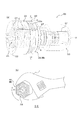
図1〜図5は、本実施形態の射出成形金型100を型閉した状態で示しており、図6は、この射出成形金型100を型開して、成形品である樹脂部材200を取り出すときの様子を示している。図7は、図1〜図6の射出成形金型100を用いた射出成形により得られる、本実施形態の樹脂部材200を示している。この樹脂部材200は、任意の種類及び用途の樹脂製品の分野に用いられてよいが、継手に用いられるのに好適なものである。図8は、図7の樹脂部材200を用いて最終的に得られる樹脂製品の一例である、継手300を示している。
[First Embodiment]
The first embodiment of the present invention will be described with reference to FIGS. 1 to 8.
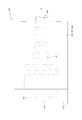
1 to 5 show the injection molding die 100 of the present embodiment in a closed state, and FIG. 6 shows the injection molding die 100 being opened to form a resin member 200 which is a molded product. It shows the state when taking out. FIG. 7 shows the resin member 200 of the present embodiment obtained by injection molding using the injection molding die 100 of FIGS. 1 to 6. The resin member 200 may be used in the field of resin products of any kind and application, but is suitable for use in a joint. FIG. 8 shows a joint 300, which is an example of a resin product finally obtained by using the resin member 200 of FIG. 7.

図1及び図2に示すように、本実施形態の射出成形金型(以下、単に金型ともいう。)100は、キャビティ面によって区画されたキャビティCVと、ランナーRから運ばれる強化繊維入りの溶融樹脂をキャビティCV内に注入するための注入口である1つ又は複数(本例では3つ)のゲートGと、キャビティCVに開口する凹部である1つ又は複数(本例では3つ)の樹脂溜まり110とを、有している。
後に詳述するように、この金型100は、キャビティCV内で樹脂が合流して樹脂の界面どうしが突き合った状態で硬化されたウェルド部Wが形成されるように構成されている。樹脂溜まり110は、ウェルド部Wの強度を向上させるために設けられている。
As shown in FIGS. 1 and 2, the injection molding die (hereinafter, also simply referred to as a die) 100 of the present embodiment contains a cavity CV partitioned by a cavity surface and a reinforcing fiber carried from a runner R. One or more gates G (three in this example) that are injection ports for injecting molten resin into the cavity CV, and one or more (three in this example) recesses that open into the cavity CV. Has a resin reservoir 110 of the above.
As will be described in detail later, the mold 100 is configured such that the welded portion W is formed in a state where the resins are merged in the cavity CV and the interfaces of the resins are abutted against each other. The resin reservoir 110 is provided to improve the strength of the weld portion W.

本実施形態の樹脂部材200は、つぎの方法で製造される。
まず、図1〜図5に示すように、金型100を閉じ、内部にキャビティCVを形成する。その状態で、強化繊維入りの溶融樹脂をランナーRからゲートGに向けて流し、ゲートGからキャビティCV内へ射出する。キャビティCV内に溶融樹脂が充填された後、キャビティCV内の樹脂を所定の程度まで冷却及び硬化させる。つぎに、図6に示すように、金型100を開いて、樹脂部材200を取り出す。以上のようにして、樹脂部材200の成形工程が完了し、図7に示すような、強化繊維入りの樹脂から構成された樹脂部材200が得られる。樹脂部材200は、本体部MBと、本体部MBに連結された1つ又は複数(本例では3つ)の突起部210とを、有している。成形工程では、キャビティCVによって本体部MBが成形されるとともに、樹脂溜まり110によって突起部210が成形される。
成形工程により得られた樹脂部材200は、そのまま最終的な樹脂製品として利用されてもよい。あるいは、成形工程後、樹脂部材200をさらに加工したり他の部材と組み立てたりすることにより、最終的な樹脂製品を得るようにしてもよい。例えば、成形工程後、樹脂部材200の突起部210を、切断する等して除去してもよい(除去工程)。
The resin member 200 of this embodiment is manufactured by the following method.
First, as shown in FIGS. 1 to 5, the mold 100 is closed to form a cavity CV inside. In that state, the molten resin containing the reinforcing fibers is poured from the runner R toward the gate G, and is injected from the gate G into the cavity CV. After the cavity CV is filled with the molten resin, the resin in the cavity CV is cooled and cured to a predetermined degree. Next, as shown in FIG. 6, the mold 100 is opened and the resin member 200 is taken out. As described above, the molding process of the resin member 200 is completed, and the resin member 200 made of the resin containing the reinforcing fibers as shown in FIG. 7 is obtained. The resin member 200 has a main body MB and one or more (three in this example) protrusions 210 connected to the main body MB. In the molding step, the main body MB is molded by the cavity CV, and the protrusion 210 is molded by the resin reservoir 110.
The resin member 200 obtained by the molding step may be used as it is as a final resin product. Alternatively, after the molding step, the resin member 200 may be further processed or assembled with other members to obtain a final resin product. For example, after the molding step, the protrusion 210 of the resin member 200 may be removed by cutting or the like (removal step).

図8の継手300は、成形工程により得られた樹脂部材200(図7)から、突起部210が除去されて、本体部MBに外筒部310が装着される(組立工程)ことにより、得られたものである。この継手300は、給水・給湯用配管への利用に好適なものであるが、水以外の流体(例えば油、薬液等の液体や、空気、ガス等の気体等)のための配管にも利用できるものである。図8の例のように、樹脂部材200から突起部210が除去された場合、本体部MBには、突起部210が除去された跡211が残る場合がある。 The joint 300 of FIG. 8 is obtained by removing the protrusion 210 from the resin member 200 (FIG. 7) obtained in the molding step and mounting the outer cylinder portion 310 on the main body MB (assembly step). It was made. This joint 300 is suitable for use in water / hot water supply pipes, but is also used for pipes for fluids other than water (for example, liquids such as oil and chemicals, and gases such as air and gas). It can be done. When the protrusion 210 is removed from the resin member 200 as in the example of FIG. 8, the trace 211 from which the protrusion 210 has been removed may remain on the main body MB.

ここで、図7及び図8を参照して、本実施形態の樹脂部材200の構成について、さらに詳しく説明する。
図7及び図8(a)に示すように、樹脂部材200の本体部MBは、まっすぐに延びる円筒状部材である。本体部MBは、本体部MBの軸方向一方側に位置する軸方向一方側部分221と、本体部MBの軸方向中間部に位置する軸方向中間部220と、本体部MBの軸方向他方側に位置する軸方向他方側部分224とを、有している。
なお、本明細書において、「円筒状部材」とは、全長にわたって外周面及び内周面の両方が円形断面を有するような形状のものに限られず、全体的に観たときに略円筒状をなす形状のものも含むものであり、延在方向の少なくとも一部分で外周面及び/又は内周面が非円形の断面をなしていてもよい。
樹脂部材200は、軸方向一方側部分221から軸方向中間部220にわたる領域の内周面に、めねじ223を有している。このめねじ223は、図示しない他の部材(例えば金属製の水道管)のおねじと接続されるように構成されている。また、このめねじ223は、本体部MBの軸方向一方側から軸方向他方側(奥側)に向かうにつれて徐々に縮径する、テーパめねじである。
図7に示すように、成形工程後かつ除去工程前の樹脂部材200の本体部MBの軸方向一方側の端面222には、突起部210が連結されている。
Here, the configuration of the resin member 200 of the present embodiment will be described in more detail with reference to FIGS. 7 and 8.
As shown in FIGS. 7 and 8 (a), the main body MB of the resin member 200 is a cylindrical member that extends straight. The main body MB has an axial one-sided portion 221 located on one side of the main body MB in the axial direction, an axial intermediate portion 220 located in the axial middle portion of the main body MB, and an axial other side of the main body MB. It has an axially opposite side portion 224 located at.
In the present specification, the "cylindrical member" is not limited to a member having a circular cross section on both the outer peripheral surface and the inner peripheral surface over the entire length, and is substantially cylindrical when viewed as a whole. It also includes an eggplant shape, and the outer peripheral surface and / or the inner peripheral surface may have a non-circular cross section at least in a part in the extending direction.
The resin member 200 has a female screw 223 on the inner peripheral surface of the region extending from the axial one-side portion 221 to the axial intermediate portion 220. The female screw 223 is configured to be connected to a screw of another member (for example, a metal water pipe) (not shown). Further, the female screw 223 is a tapered female screw whose diameter gradually decreases from one side in the axial direction of the main body MB toward the other side (back side) in the axial direction.
As shown in FIG. 7, the protrusion 210 is connected to the end surface 222 on one side in the axial direction of the main body MB of the resin member 200 after the molding step and before the removing step.

なお、本明細書において、樹脂部材200又は本体部MBの「軸方向」とは、本体部MBのなす円筒形状の中心軸線Oに平行な方向を指す。本例では、中心軸線Oは直線状に延びている。また、樹脂部材200又は本体部MBの「軸方向一方側」とは、軸方向両側のうち、めねじ223が形成された側を指し、樹脂部材200又は本体部MBの「軸方向他方側」とは、その反対側を指す。また、樹脂部材200又は本体部MBの「軸直方向」とは、軸方向に垂直な方向を指す。 In the present specification, the "axial direction" of the resin member 200 or the main body MB refers to a direction parallel to the cylindrical central axis O formed by the main body MB. In this example, the central axis O extends linearly. Further, the "one side in the axial direction" of the resin member 200 or the main body MB refers to the side on which the female screw 223 is formed on both sides in the axial direction, and is the "other side in the axial direction" of the resin member 200 or the main body MB. Refers to the other side. Further, the "axial direction" of the resin member 200 or the main body MB refers to a direction perpendicular to the axial direction.

本実施形態の樹脂部材200は、強化繊維入りの樹脂から構成されている。
樹脂部材200を構成する樹脂としては、任意の樹脂を用いてよい。例えば図8の例のように樹脂部材200が継手300に用いられる場合、樹脂部材200を構成する樹脂としては、例えばポリフェニレンサルファイド(PPS:Polyphenylenesulfide)を用いると、耐熱性、耐薬品性等に優れているので好適である。
樹脂部材200を構成する樹脂に含められている強化繊維は、樹脂の強度を強化するために含められている。強化繊維としては、樹脂の強度を向上できるものである限り、任意の繊維を用いてよい。例えば図8の例のように樹脂部材200が継手300に用いられる場合、強化繊維としては、例えばガラス繊維を用いると、樹脂部材200ひいては継手300の強度を、具体的には耐割れ性及び耐クリープ変形性を、向上できるので、よい。
樹脂部材200は、めねじ223を含めた全体が樹脂により一体に成形されているので、樹脂部材200の少なくとも一部分(例えばめねじ223のみ)を金属製とした場合に比べて、樹脂部材200ひいては継手300の軽量化及び低コスト化が可能である。また、樹脂部材200は、樹脂に強化繊維が含められているので、少なくとも一部分を金属製とした場合と同等の強度を確保することが可能となる。
The resin member 200 of the present embodiment is made of a resin containing reinforcing fibers.
Any resin may be used as the resin constituting the resin member 200. For example, when the resin member 200 is used for the joint 300 as in the example of FIG. 8, when polyphenylene sulfide (PPS) is used as the resin constituting the resin member 200, the heat resistance, chemical resistance, and the like are excellent. It is suitable because it is.
The reinforcing fibers contained in the resin constituting the resin member 200 are included in order to enhance the strength of the resin. As the reinforcing fiber, any fiber may be used as long as the strength of the resin can be improved. For example, when the resin member 200 is used for the joint 300 as in the example of FIG. 8, when glass fiber is used as the reinforcing fiber, the strength of the resin member 200 and thus the joint 300, specifically, crack resistance and crack resistance It is good because the creep deformability can be improved.
Since the entire resin member 200 including the female screw 223 is integrally molded with resin, the resin member 200 and thus the resin member 200, as compared with the case where at least a part of the resin member 200 (for example, only the female screw 223) is made of metal, It is possible to reduce the weight and cost of the joint 300. Further, since the resin member 200 contains reinforcing fibers in the resin, it is possible to secure the same strength as when at least a part of the resin member 200 is made of metal.

樹脂部材200の軸方向一方側部分221及び軸方向他方側部分224は、それらの外周面が、軸直方向断面において円形である。
樹脂部材200の軸方向中間部分220は、その外周面が軸直方向断面において多角形状(本例では六角形)をなしており、これによりトルク入力部分220を構成している。トルク入力部分220は、外周面が軸直方向断面において多角形状をなすため、例えば継手300の施工時にめねじ223を他の部材のおねじに対して締め付けるとき等において、図8(b)に示すようにレンチ等の工具Tがトルク入力部分220の互いに対向する一対の平坦面を外側から掴んだ状態で、工具Tからのトルクがしっかりと入力されるようにされている。本例では、トルク入力部分220の外周面に、複数の凹部220aが形成されている。
図の例では、軸方向一方側部分221の外径とトルク入力部分220の外径(トルク入力部分220の多角形断面の外接円の径)が、ほぼ同じであり、また、軸方向に沿ってほぼ一定である。トルク入力部分220の内周面には、テーパめねじ223の末端部が形成されており、すなわちそこでの内径が軸方向一方側部分221よりもやや小さくされている。これにより、トルク入力部分220の周壁の厚さひいては強度を確保して、上述の工具Tからのトルクに耐えられるようにされている。
軸方向他方側部分224の外径は、軸方向一方側部分221やトルク入力部分220の外径よりも、大幅に小さくされている。図8(a)の継手300では、軸方向他方側部分224に、それより大径の外筒部310が装着されている。樹脂部材200の軸方向他方側部分224と外筒部310との間には、円環状の空間が区画されており、この環状空間は、図示しない円管状部材(例えばポリブテン製又は架橋ポリエチレン製のパイプ)が差し込まれるように構成されている。
突起部210については、後にさらに詳しく説明する。
The outer peripheral surfaces of the axial one-side portion 221 and the axial other-side portion 224 of the resin member 200 are circular in the axial cross section.
The outer peripheral surface of the axial intermediate portion 220 of the resin member 200 has a polygonal shape (hexagon in this example) in the axial cross section, thereby forming the torque input portion 220. Since the outer peripheral surface of the torque input portion 220 has a polygonal shape in the cross section in the axial direction, for example, when the female screw 223 is tightened to the screw of another member during the construction of the joint 300, FIG. 8 (b) shows. As shown, the torque from the tool T is firmly input while the tool T such as a wrench grips the pair of flat surfaces of the torque input portion 220 facing each other from the outside. In this example, a plurality of recesses 220a are formed on the outer peripheral surface of the torque input portion 220.
In the example of the figure, the outer diameter of the one side portion 221 in the axial direction and the outer diameter of the torque input portion 220 (the diameter of the circumscribed circle of the polygonal cross section of the torque input portion 220) are almost the same, and are also along the axial direction. Is almost constant. An end portion of the tapered female screw 223 is formed on the inner peripheral surface of the torque input portion 220, that is, the inner diameter thereof is slightly smaller than that of the axial one-side portion 221. As a result, the thickness and strength of the peripheral wall of the torque input portion 220 are ensured so that the torque from the above-mentioned tool T can be withstood.
The outer diameter of the axially opposite side portion 224 is significantly smaller than the outer diameter of the axially unidirectional side portion 221 and the torque input portion 220. In the joint 300 of FIG. 8A, an outer cylinder portion 310 having a larger diameter is mounted on the other side portion 224 in the axial direction. An annular space is partitioned between the axially opposite side portion 224 of the resin member 200 and the outer cylinder portion 310, and this annular space is made of an annular tubular member (for example, made of polybutene or cross-linked polyethylene) (for example, made of polybutene or cross-linked polyethylene). The pipe) is configured to be inserted.
The protrusion 210 will be described in more detail later.

つぎに、図1〜図6を参照して、上述した本実施形態の樹脂部材200を成形するように構成された、本実施形態の射出成形金型100の構成について、さらに詳しく説明する。
金型100は、外型部101〜104と、内型部105、106とを、有している。金型100は、図1〜図5に示すような閉じた状態にあるとき、外型部101〜104の内側のキャビティ面と、内型部105、106の外側のキャビティ面とにより、キャビティCVを区画する。
図2に示すように、このキャビティCVは、まっすぐに延びる円筒形状に構成されており、これにより、円筒状部材である樹脂部材200の本体部MBを成形するように構成されている。外型部101〜104のうち最も軸方向一方側に位置する外型部101は、樹脂部材200の軸方向一方側端面222を成形するように構成された軸方向一方側端面用キャビティ面122を有している。他の外型部102〜104は、外型部101に対して軸方向他方側で、周方向に沿って配列されており、それぞれが、樹脂部材200の本体部MBの全長にわたる外周面を成形するように構成された外周面用キャビティ面を有している。外型部102〜104の各外周面用キャビティ面は、それぞれ、樹脂部材200の軸方向一方側部分221の外周面を成形するように構成された軸方向一方側部分用キャビティ面121と、樹脂部材200のトルク入力部分220の外周面を成形するように構成されたトルク入力部分用キャビティ面120と、樹脂部材200の軸方向他方側部分224の外周面を成形するように構成された軸方向他方側部分用キャビティ面124とを、有している。内型部105、106のうち軸方向一方側に位置する内型部105は、樹脂部材200のめねじ223を成形するように構成されためねじ用キャビティ面123を有しており、めねじ用キャビティ面123より軸方向一方側の部分が、外型部101に設けられた内型収容部101a(図6(a))に収容されるように構成されている。めねじ用キャビティ面123は、キャビティCVの軸方向一方側から軸方向他方側(奥側)に向かうにつれて徐々に縮径する。他方の内型部106は、樹脂部材200の軸方向他方側部分224の内周面を成形するように構成された軸方向他方側部分用キャビティ面125を有している。
外型部101は、樹脂溜まり110を有しており、樹脂溜まり110は、軸方向一方側端面用キャビティ面122に開口している。樹脂溜まり110は、キャビティCV内に溶融樹脂が射出される間、キャビティCV内の溶融樹脂の一部が流れ込んで溜まる部分であり、樹脂部材200における突起部210を成形するものである。
Next, with reference to FIGS. 1 to 6, the configuration of the injection molding die 100 of the present embodiment, which is configured to mold the resin member 200 of the present embodiment described above, will be described in more detail.
The mold 100 has outer mold portions 101 to 104 and inner mold portions 105 and 106. When the mold 100 is in the closed state as shown in FIGS. 1 to 5, the cavity CV is formed by the inner cavity surface of the outer mold portions 101 to 104 and the outer cavity surface of the inner mold portions 105 and 106. To partition.
As shown in FIG. 2, the cavity CV is configured to have a cylindrical shape extending straight, thereby forming a main body MB of the resin member 200, which is a cylindrical member. The outer mold portion 101 located on one side of the outer mold portions 101 to 104 on one side in the axial direction has a cavity surface 122 for one side end surface in the axial direction configured to form the one end surface 222 in the axial direction of the resin member 200. Have. The other outer mold portions 102 to 104 are arranged along the circumferential direction on the other side in the axial direction with respect to the outer mold portion 101, and each forms an outer peripheral surface over the entire length of the main body portion MB of the resin member 200. It has a cavity surface for an outer peripheral surface configured to be used. The cavity surfaces for the outer peripheral surfaces of the outer mold portions 102 to 104 are the cavity surface 121 for the one side portion in the axial direction configured to form the outer peripheral surface of the one side portion 221 in the axial direction of the resin member 200, and the resin. The cavity surface 120 for the torque input portion configured to form the outer peripheral surface of the torque input portion 220 of the member 200 and the axial direction configured to form the outer peripheral surface of the other side portion 224 in the axial direction of the resin member 200. It has a cavity surface 124 for the other side portion. Of the inner mold portions 105 and 106, the inner mold portion 105 located on one side in the axial direction has a screw cavity surface 123 because it is configured to form the female screw 223 of the resin member 200, and is used for the female screw. A portion on one side in the axial direction from the cavity surface 123 is configured to be accommodated in the inner mold accommodating portion 101a (FIG. 6A) provided in the outer mold portion 101. The diameter of the female thread cavity surface 123 gradually decreases from one axial side of the cavity CV toward the other axial direction (back side). The other inner mold portion 106 has a cavity surface 125 for the other side portion in the axial direction configured to form an inner peripheral surface of the other side portion 224 in the axial direction of the resin member 200.
The outer mold portion 101 has a resin reservoir 110, and the resin reservoir 110 is open to the cavity surface 122 for one end surface in the axial direction. The resin reservoir 110 is a portion where a part of the molten resin in the cavity CV flows and accumulates while the molten resin is injected into the cavity CV, and forms a protrusion 210 in the resin member 200.

なお、本明細書において、金型100又はキャビティCVの「軸方向」とは、キャビティCVのなす円筒形状の中心軸線Oに平行な方向を指す。本例では、中心軸線Oは直線状に延びている。また、金型100又はキャビティCVの「軸方向一方側」とは、軸方向両側のうち、めねじ用キャビティ面123が配置された側を指し、金型100又はキャビティCVの「軸方向他方側」とは、その反対側を指す。また、金型100又はキャビティCVの「軸直方向」とは、軸方向に垂直な方向を指す。 In the present specification, the "axial direction" of the mold 100 or the cavity CV refers to a direction parallel to the central axis O of the cylindrical shape formed by the cavity CV. In this example, the central axis O extends linearly. Further, the "one side in the axial direction" of the mold 100 or the cavity CV refers to the side on both sides in the axial direction in which the female thread cavity surface 123 is arranged, and the "other side in the axial direction" of the mold 100 or the cavity CV. "" Refers to the other side. Further, the "axial direction" of the mold 100 or the cavity CV refers to a direction perpendicular to the axial direction.

離型時では、図6に示すように、外型部102〜104がそれぞれ成形品である樹脂部材200から径方向外側へと外され、外型部101が樹脂部材200から軸方向一方側へ外される。また、内型部105が回転されながら樹脂部材200から軸方向一方側へと引き抜かれ、内型部106が樹脂部材200から軸方向他方側へと引き抜かれる。
なお、金型100は、本例と同じキャビティCVを、本例の外型部101〜104及び内型部105、106とは異なる構成の外型部及び内型部によって区画するようにしてもよい。
At the time of mold release, as shown in FIG. 6, the outer mold portions 102 to 104 are removed from the resin member 200, which is a molded product, outward in the radial direction, and the outer mold portion 101 is moved outward from the resin member 200 in the axial direction. Be removed. Further, the inner mold portion 105 is pulled out from the resin member 200 to one side in the axial direction while rotating, and the inner mold portion 106 is pulled out from the resin member 200 to the other side in the axial direction.
In the mold 100, the same cavity CV as in this example may be partitioned by an outer mold portion and an inner mold portion having a configuration different from that of the outer mold portions 101 to 104 and the inner mold portions 105 and 106 of this example. Good.

以下では、金型100の説明において、特に断りがない限り、金型100は閉じた状態にあるものとする。 In the following, in the description of the mold 100, unless otherwise specified, the mold 100 is assumed to be in a closed state.

軸方向一方側部分用キャビティ面121及び軸方向他方側部分用キャビティ面124は、軸直方向断面において円形である。
トルク入力部分用キャビティ面120は、図2(b)に示すように、軸直方向断面において多角形状(本例では六角形)をなしている。図の例では、トルク入力部分用キャビティ面120に、樹脂部材200のトルク入力部分220の複数の凹部220aを形成するように構成された、複数の凸部120a(図4)が形成されている。
図の例では、軸方向一方側部分用キャビティ面121の外径とトルク入力部分用キャビティ面120の外径(トルク入力部分用キャビティ面120の多角形断面の外接円の径)が、ほぼ同じである。トルク入力部分用キャビティ面120の内周側には、めねじ用キャビティ面223の末端部が配置されており、すなわちそこでのキャビティCVの内径が軸方向一方側部分用キャビティ面121よりもやや小さくされている。
軸方向他方側部分用キャビティ面124の外径は、軸方向一方側部分用キャビティ面121やトルク入力部分用キャビティ面120の外径よりも、大幅に小さくされている。
The cavity surface 121 for the one side portion in the axial direction and the cavity surface 124 for the other side portion in the axial direction are circular in the axial cross section.
As shown in FIG. 2B, the cavity surface 120 for the torque input portion has a polygonal shape (hexagon in this example) in the cross section in the axial direction. In the example of the figure, a plurality of convex portions 120a (FIG. 4) are formed on the cavity surface 120 for the torque input portion so as to form a plurality of concave portions 220a of the torque input portion 220 of the resin member 200. ..
In the example of the figure, the outer diameter of the cavity surface 121 for one side in the axial direction and the outer diameter of the cavity surface 120 for the torque input portion (the diameter of the circumscribed circle of the polygonal cross section of the cavity surface 120 for the torque input portion) are almost the same. Is. On the inner peripheral side of the cavity surface 120 for the torque input portion, the end portion of the cavity surface 223 for the female thread is arranged, that is, the inner diameter of the cavity CV there is slightly smaller than the cavity surface 121 for the one side portion in the axial direction. Has been done.
The outer diameter of the cavity surface 124 for the other side portion in the axial direction is significantly smaller than the outer diameter of the cavity surface 121 for the one side portion in the axial direction and the cavity surface 120 for the torque input portion.

図2に示すように、トルク入力部分用キャビティ面120の軸方向他方側には、より具体的に本例においてトルク入力部分用キャビティ面120の軸方向他方側の端部の近傍には、軸方向一方側を向くように指向されてキャビティCVに開口した、ゲートGが設けられている。図の例では、3つのゲートGが、周方向に等間隔に(120°ずつ離れた角度位置に)設けられている。なお、本明細書において、金型100又は樹脂部材200における「角度位置」とは、中心軸線O周りの角度位置を指しており、周方向位置に相当する。 As shown in FIG. 2, the shaft is located on the other side of the torque input portion cavity surface 120 in the axial direction, and more specifically, in the vicinity of the end portion of the torque input portion cavity surface 120 on the other side in the axial direction. A gate G is provided that is oriented so as to face one side and opens into the cavity CV. In the example of the figure, three gates G are provided at equal intervals in the circumferential direction (at angular positions separated by 120 °). In the present specification, the "angle position" in the mold 100 or the resin member 200 refers to an angular position around the central axis O, and corresponds to a circumferential position.

図3(b)に示すように、樹脂溜まり110のキャビティCVへの開口端面110S(樹脂溜まり110とキャビティCVとの境界面)は、非正円形状に形成されており、より具体的に本例では、一方向の長さがそれに垂直な方向の長さよりも長い平行四辺形状に形成されている。
そして、樹脂溜まり110のキャビティCVへの開口端面110Sに沿った第1断面において、キャビティCVの幅中心線CL12の垂線n12に沿って測ったときの、樹脂溜まり110の幅中心線CL11とキャビティCVの幅中心線CL12との間の距離CLDは、キャビティCVの幅中心線CL12に沿って、常に一定ではなく、少なくとも一部分で変化するようにされている。
ここで、開口端面110Sに沿った「第1断面」とは、開口端面110Sを含む仮想平面に沿った金型100の断面である。本例において、第1断面は、軸直方向に平行な断面であり、図3(b)の断面(図2のC−C線断面)である。
第1断面における樹脂溜まり110の「幅中心線CL11」とは、第1断面における開口端面110Sの延在方向(長手方向)に垂直な方向を幅方向としたとき、開口端面110Sの幅方向の中心を通る線をいい、本例では、開口端面110Sのなす平行四辺形状の互いに対向する一対の長辺からの等距離線である。また、第1断面における樹脂溜まり110の幅中心線CL11の「垂線n11」とは、樹脂溜まり110の幅中心線CL11上の任意の点での接線に対して垂直であるとともに、該点を通る、線である。
第1断面におけるキャビティCVの「幅中心線CL12」とは、第1断面におけるキャビティCVの延在方向(長手方向)に垂直な方向を幅方向としたときのキャビティCVの幅方向の中心を通る線をいい、本例では、第1断面におけるキャビティCVのなす円環形状の外周縁と内周縁からの等距離線である。また、第1断面におけるキャビティCVの幅中心線CL12の「垂線n12」とは、キャビティCVの幅中心線CL12上の任意の点での接線に対して垂直であるとともに、該点を通る、線である。
As shown in FIG. 3B, the opening end surface 110S of the resin reservoir 110 to the cavity CV (the boundary surface between the resin reservoir 110 and the cavity CV) is formed in a non-circular shape, and more specifically, the present In the example, it is formed in a parallel quadrilateral shape in which the length in one direction is longer than the length in the direction perpendicular to it.
Then, in the first cross section along the opening end surface 110S of the resin pool 110 to the cavity CV, the width center line CL11 and the cavity CV of the resin pool 110 when measured along the vertical line n12 of the width center line CL12 of the cavity CV. The distance CLD between the width center line CL12 and the width center line CL12 of the cavity CV is not always constant but changes at least in a part along the width center line CL12 of the cavity CV.
Here, the "first cross section" along the opening end face 110S is a cross section of the mold 100 along the virtual plane including the opening end face 110S. In this example, the first cross section is a cross section parallel to the axial direction, and is a cross section of FIG. 3B (cross section taken along line CC of FIG. 2).
The "width center line CL11" of the resin pool 110 in the first cross section is the width direction of the opening end surface 110S when the direction perpendicular to the extending direction (longitudinal direction) of the opening end surface 110S in the first cross section is defined as the width direction. A line passing through the center, and in this example, is an equidistant line from a pair of long sides facing each other in a parallel quadrilateral shape formed by the opening end surface 110S. Further, the "perpendicular line n11" of the width center line CL11 of the resin pool 110 in the first cross section is perpendicular to the tangent line at an arbitrary point on the width center line CL11 of the resin pool 110 and passes through the point. , A line.
The "width center line CL12" of the cavity CV in the first cross section passes through the center in the width direction of the cavity CV when the direction perpendicular to the extending direction (longitudinal direction) of the cavity CV in the first cross section is defined as the width direction. A line, in this example, is an equidistant line from the outer and inner edges of the ring shape formed by the cavity CV in the first cross section. Further, the "perpendicular line n12" of the width center line CL12 of the cavity CV in the first cross section is a line perpendicular to and passing through the tangent line at an arbitrary point on the width center line CL12 of the cavity CV. Is.

つぎに、上述のように構成された金型100の作用について、図5を参照しながら説明する。
成形工程において、強化繊維入りの溶融樹脂がゲートGからキャビティCV内に射出される間、溶融樹脂は、最初、軸方向一方側に向かって、トルク入力部分用キャビティ面120の内側のキャビティCV内、それから軸方向一方側部分用キャビティ面121の内側のキャビティCV内を、周方向に広がりながら軸方向に順次移動し、そこからさらに樹脂溜まり110の内部へと流れていく。ゲートGより軸方向一方側のキャビティCV及び樹脂溜まり110が樹脂で充填されると、つぎに、樹脂は、軸方向他方側に向かって、軸方向他方側部分用キャビティ面124の内側のキャビティCV内を、軸方向に流れ、そこも樹脂で充填される。このようにして、キャビティCVの全体が樹脂で充填される。
Next, the operation of the mold 100 configured as described above will be described with reference to FIG.
In the molding process, while the molten resin containing the reinforcing fibers is injected from the gate G into the cavity CV, the molten resin is initially directed toward one side in the axial direction in the cavity CV inside the cavity surface 120 for the torque input portion. Then, it sequentially moves in the axial direction while expanding in the circumferential direction in the cavity CV inside the cavity surface 121 for one side portion in the axial direction, and further flows into the resin pool 110 from there. When the cavity CV on one side in the axial direction and the resin reservoir 110 from the gate G are filled with resin, the resin is then filled in the cavity CV inside the cavity surface 124 for the other side in the axial direction toward the other side in the axial direction. It flows in the axial direction and is also filled with resin. In this way, the entire cavity CV is filled with resin.

ここで、仮に、金型100に樹脂溜まり110が設けられておらず、軸方向一方側部分用キャビティ面121及び軸方向一方側端面用キャビティ面122がそれぞれ凹凸のない平滑面のみからなる場合、樹脂流動方向(本例では軸方向)においてゲートGから離れた、軸方向一方側部分用キャビティ面121の内側のキャビティCVでは、各ゲートGの位置(角度位置)であるゲート位置GPどうしからキャビティCVに沿って等距離にある位置(角度位置)であるゲート間位置BGPの各々で、ウェルド部Wが、軸方向及び径方向に平行な平面状に形成されやすくなる。また、この場合、ウェルド部Wでは、樹脂どうしの界面の両側において、樹脂内の各強化繊維Fが、ウェルド部Wの延在方向(ウェルド延在方向。本例では軸方向)に平行に延在する(配向される)おそれが高くなる。
ここで、本明細書において、「樹脂流動方向」とは、キャビティCV内でゲートGから射出された樹脂が流れる大まかな方向を近似した方向であり、本例ではゲートGの指向方向ひいては軸方向一方側に向かう方向に相当する。また、「ウェルド延在方向」は、ウェルド部Wの延在方向を一方向に近似した方向であり、ゲート間位置BGPを通る仮想平面の延在方向を一方向に近似した方向に相当し、本例では軸方向である。また、本明細書では、ウェルド延在方向に交差する方向を、「ウェルド交差方向」ということがある。
なお、樹脂流動方向(本例では軸方向)においてゲートGから近い、トルク入力部分用キャビティ面120の内側のキャビティCV内では、射出中にゲートGから射出されたばかりの高温の樹脂どうしが合流しても樹脂の界面は消えて残りにくく、ウェルド部Wは形成されにくい。樹脂流動方向においてゲートGから遠ければ遠いほど、すなわち軸方向一方側端面222に近ければ近いほど、ゲートGから射出されてから時間が経ち、やや冷却された樹脂どうしが合流すると、そこで界面が残りやすく、ウェルド部Wが形成されやすくなる。
上述のように、仮に、ウェルド部Wが軸方向に沿ってまっすぐに形成され、かつ、ウェルド部Wにおける樹脂内の各強化繊維Fが、ウェルド部Wの延在方向に平行に配向される場合、成形品である樹脂部材200は、径方向の外力に対する強度が十分でないおそれがある。なお、樹脂を強化繊維Fで補強していても、ウェルド部Wにおける各強化繊維Fがウェルド部Wの延在方向に平行に配向されていると、ウェルド部Wの強度は、実質上、樹脂のみの強度しか得られない。
本例の樹脂部材200は、軸方向一方側部分221及びトルク入力部分220の内周側にめねじ223を有しているため、例えば継手300の施工時において、おねじ付きの外部部材がめねじ223にねじ込まれる際に、軸方向一方側部分221及びトルク入力部分220は、拡径方向の力を受ける。このとき、軸方向一方側部分221に形成されたウェルド部Wの強度が十分でないと、軸方向一方側部分221に破損が生じるおそれがある。このため、ウェルド部Wには、十分な強度を持たせる必要がある。特に、本例のめねじ223はテーパめねじであることから、軸方向一方側部分221の周壁の厚さは、トルク入力部分220に比べて薄く、しかも軸方向一方側端面222に近ければ近いほど薄くなる。また、めねじ223が平行めねじである場合に比べて、おねじ付きの外部部材から入力される拡径方向の力が大きくなるおそれがある。その分、ウェルド部Wの強度向上の必要性は高く、特に、軸方向一方側端面222に近ければ近いほどその必要性は高まる。
Here, if the mold 100 is not provided with the resin reservoir 110, and the cavity surface 121 for one side portion in the axial direction and the cavity surface 122 for one end surface in the axial direction are each composed of only smooth surfaces having no unevenness. In the cavity CV inside the cavity surface 121 for one side portion in the axial direction, which is separated from the gate G in the resin flow direction (axial direction in this example), the cavity is formed from the gate positions GP which are the positions (angle positions) of the gates G. At each of the gate-to-gate positions BGP, which are equidistant positions (angle positions) along the CV, the weld portion W is likely to be formed in a planar shape parallel to the axial direction and the radial direction. Further, in this case, in the weld portion W, on both sides of the interface between the resins, each reinforcing fiber F in the resin extends parallel to the extending direction of the weld portion W (weld extending direction, in this example, the axial direction). The risk of being (oriented) increases.
Here, in the present specification, the "resin flow direction" is a direction that approximates the rough direction in which the resin ejected from the gate G flows in the cavity CV. In this example, the direction direction of the gate G and thus the axial direction. Corresponds to the direction toward one side. Further, the "weld extension direction" is a direction that approximates the extension direction of the weld portion W in one direction, and corresponds to a direction that approximates the extension direction of the virtual plane passing through the intergate position BGP in one direction. In this example, it is in the axial direction. Further, in the present specification, the direction of intersection in the weld extension direction may be referred to as "weld intersection direction".
In the cavity CV inside the cavity surface 120 for the torque input portion, which is close to the gate G in the resin flow direction (axial direction in this example), the high-temperature resins that have just been injected from the gate G merge during injection. However, the interface of the resin disappears and is hard to remain, and the weld portion W is hard to be formed. The farther the resin flows from the gate G, that is, the closer it is to the one end surface 222 in the axial direction, the more time has passed since the resin was ejected from the gate G, and when the slightly cooled resins merge, the interface remains there. It is easy, and the weld portion W is easily formed.
As described above, if the weld portion W is formed straight along the axial direction and each reinforcing fiber F in the resin in the weld portion W is oriented parallel to the extending direction of the weld portion W. The resin member 200, which is a molded product, may not have sufficient strength against an external force in the radial direction. Even if the resin is reinforced with the reinforcing fibers F, if each reinforcing fiber F in the weld portion W is oriented parallel to the extending direction of the weld portion W, the strength of the weld portion W is substantially resin. Only strength can be obtained.
Since the resin member 200 of this example has a female thread 223 on the inner peripheral side of the axial direction one side portion 221 and the torque input portion 220, for example, when the joint 300 is constructed, the external member with a male thread is a female thread. When screwed into the 223, the axial one-sided portion 221 and the torque input portion 220 receive a force in the diameter-expanding direction. At this time, if the strength of the weld portion W formed on the axial one-side portion 221 is not sufficient, the axial one-side portion 221 may be damaged. Therefore, the weld portion W needs to have sufficient strength. In particular, since the female thread 223 of this example is a tapered female thread, the thickness of the peripheral wall of the axial one-sided portion 221 is thinner than that of the torque input portion 220, and is closer to the axial one-sided end surface 222. It gets thinner. Further, as compared with the case where the female screw 223 is a parallel female screw, the force in the diameter expansion direction input from the external member with the male screw may be larger. Therefore, the need for improving the strength of the weld portion W is high, and in particular, the closer it is to the one side end surface 222 in the axial direction, the greater the need for it.

一方、本実施形態においては、上述のように、金型100に樹脂溜まり110が設けられており、樹脂溜まり110のキャビティCVへの開口端面110Sに沿った第1断面において、キャビティCVの幅中心線CL12の垂線n12に沿って測ったときの、樹脂溜まり110の幅中心線CL11とキャビティCVの幅中心線CL12との間の距離CLDが、キャビティCVの幅中心線CL12に沿って、常に一定ではなく、少なくとも一部分で変化する(図の例では常に変化する)ようにされている。これにより、図5に概略的に示すように、射出中において溶融樹脂が樹脂溜まり110に流れ込む直前に、軸直方向断面におけるキャビティCVの幅方向(キャビティCVの延在方向に垂直な方向。キャビティCVの厚さ方向。)の広い範囲において、樹脂の流れが乱れて、樹脂が3次元的に様々な方向に流れる。これにより、ゲート間位置BGPの近傍に形成されるウェルド部Wの形状が、軸方向にまっすぐ延びた形状でなく、例えば3次元的に観てぼやけた形状、傾斜した形状、あるいは曲がった形状になる等、3次元的に複雑に乱れた形状となる。よって、ウェルド部Wの強度を向上できる。また、ゲート間位置BGPの近傍、ひいてはウェルド部Wの近傍では、軸直方向断面におけるキャビティCVの幅方向の広い範囲において、樹脂内の強化繊維Fの向きが乱れて、強化繊維Fが3次元的に様々な方向に配向されるので、軸方向に交差する向き、ひいてはウェルド交差方向に、配向される強化繊維Fの割合が高くなる。よって、これによっても、ウェルド部Wの強度を向上できる。
なお、仮に、第1断面において、キャビティCVの幅中心線CL12の垂線n12に沿って測ったときの、樹脂溜まり110の幅中心線CL11とキャビティCVの幅中心線CL12との間の距離CLDが、キャビティCVの幅中心線CL12に沿って、常に一定である場合、ゲート間位置BGPの近傍ひいてはウェルド部Wの近傍において、樹脂の流動方向や強化繊維Fの配向の向きを、軸直方向断面におけるキャビティCVの幅方向においてさほど広範囲に、また、さほど複雑に、乱すことができない。
On the other hand, in the present embodiment, as described above, the resin reservoir 110 is provided in the mold 100, and the width center of the cavity CV in the first cross section along the opening end surface 110S of the resin reservoir 110 to the cavity CV. The distance CLD between the width center line CL11 of the resin pool 110 and the width center line CL12 of the cavity CV when measured along the perpendicular line n12 of the line CL12 is always constant along the width center line CL12 of the cavity CV. Instead, it is designed to change at least in part (always change in the example shown). As a result, as schematically shown in FIG. 5, immediately before the molten resin flows into the resin reservoir 110 during injection, the width direction of the cavity CV in the axial cross section (the direction perpendicular to the extending direction of the cavity CV). In a wide range of CV thickness direction), the flow of the resin is disturbed, and the resin flows in various directions three-dimensionally. As a result, the shape of the weld portion W formed in the vicinity of the inter-gate position BGP is not a shape that extends straight in the axial direction, but a shape that is three-dimensionally blurred, inclined, or curved. It becomes a three-dimensionally complicated and disordered shape. Therefore, the strength of the weld portion W can be improved. Further, in the vicinity of the inter-gate position BGP, and by extension, in the vicinity of the weld portion W, the orientation of the reinforcing fibers F in the resin is disturbed in a wide range in the width direction of the cavity CV in the axial cross section, and the reinforcing fibers F are three-dimensional. Since the fibers are oriented in various directions, the proportion of the reinforcing fibers F oriented in the axially intersecting direction, and thus in the weld crossing direction, becomes high. Therefore, the strength of the weld portion W can also be improved by this.
It should be noted that, in the first cross section, the distance CLD between the width center line CL11 of the resin pool 110 and the width center line CL12 of the cavity CV when measured along the perpendicular line n12 of the width center line CL12 of the cavity CV is , When the width center line CL12 of the cavity CV is always constant, the direction of resin flow and the direction of orientation of the reinforcing fiber F in the vicinity of the gate-to-gate position BGP and thus in the vicinity of the weld portion W are cross-sectionally oriented in the axial direction. Can not be disturbed so extensively and so complicatedly in the width direction of the cavity CV in.

上述の構成の樹脂溜まり110によって成形される突起部210は、つぎの構成を有する。
図7(b)に示すように、突起部210の本体部MBへの連結端面210S(突起部210と本体部MBとの境界面)は、非正円形状に形成されており、より具体的に本例では、一方向の長さがそれに垂直な方向の長さよりも長い平行四辺形状に形成されている。
そして、突起部210の本体部MBへの連結端面210Sに沿った第1断面において、本体部MBの幅中心線CL22の垂線n22に沿って測ったときの、突起部210の幅中心線CL21と本体部MBの幅中心線CL22との間の距離CLD’が、本体部MBの幅中心線CL22に沿って、少なくとも一部分で変化する(図の例では常に変化する)ようにされている。
ここで、連結端面210Sに沿った「第1断面」とは、連結端面210Sを含む仮想平面に沿った樹脂部材200の断面である。本例において、第1断面は、軸直方向に平行な断面である。
第1断面における突起部210の「幅中心線CL21」とは、第1断面における連結端面210Sの延在方向(長手方向)に垂直な方向を幅方向としたとき、連結端面210Sの幅方向の中心を通る線をいい、本例では、連結端面210Sのなす平行四辺形状の互いに対向する一対の長辺からの等距離線である。
第1断面における本体部MBの「幅中心線CL22」とは、第1断面における本体部MBの延在方向(長手方向)に垂直な方向を幅方向としたときの本体部MBの幅方向の中心を通る線をいい、本例では、第1断面における本体部MBのなす円環形状の外周縁と内周縁からの等距離線である。また、第1断面における本体部MBの幅中心線CL22の「垂線n22」とは、本例のように本体部MBの幅中心線CL22が非直線である場合、本体部MBの幅中心線CL22上の任意の点での接線に対して垂直であるとともに、該点を通る、線である。
図7及び図8では、便宜のために、ゲートG、ゲート位置GP、及びゲート間位置BGPを、樹脂部材200とともに示している。樹脂部材200には、ゲートGの位置に、射出成形の際に形成されたゲートGの跡が残ることがある。樹脂部材200が有するゲートGの跡から、ゲートGの位置及びその指向方向(ひいてはゲートGから樹脂が射出される方向)を特定できるので、それらと樹脂部材200の形状から特定されるキャビティCVの形状とに基づいて、キャビティCV内での樹脂流動方向、ゲート位置GP、及びゲート間位置BGPを、特定することができる。
上述のような構成を有する突起部210を備えた樹脂部材200は、金型100の樹脂溜まり110の作用効果について上述したように、射出成形時に軸方向一方側部分221におけるゲート間位置BGPの近傍に形成されるウェルド部Wの形状が、軸方向にまっすぐ延びた形状でなく、3次元的に複雑に乱れた形状となる。よって、ウェルド部Wの強度を向上できる。また、ゲート間位置BGPの近傍、ひいてはウェルド部Wの近傍では、軸直方向断面における本体部MBの幅方向(本体部MBの厚さ方向)の広い範囲において、樹脂内の強化繊維Fの向きが乱れて、強化繊維Fが3次元的に様々な方向に配向されるので、軸方向に交差する向き、ひいてはウェルド交差方向に、配向される強化繊維Fの割合が高くなる。よって、これによっても、ウェルド部Wの強度を向上できる。
The protrusion 210 formed by the resin reservoir 110 having the above-described configuration has the following configuration.
As shown in FIG. 7B, the connecting end surface 210S (the boundary surface between the protrusion 210 and the main body MB) of the protrusion 210 to the main body MB is formed in a non-circular shape, and is more specific. In this example, it is formed in a parallel quadrilateral shape in which the length in one direction is longer than the length in the direction perpendicular to it.
Then, in the first cross section along the end surface 210S of the protrusion 210 connected to the main body MB, the width center line CL21 of the protrusion 210 is measured along the vertical line n22 of the width center line CL22 of the main body MB. The distance CLD'between the width center line CL22 of the main body MB is changed at least in a part (always changes in the example of the figure) along the width center line CL22 of the main body MB.
Here, the "first cross section" along the connecting end face 210S is a cross section of the resin member 200 along the virtual plane including the connecting end face 210S. In this example, the first cross section is a cross section parallel to the axial direction.
The "width center line CL21" of the protrusion 210 in the first cross section is the width direction of the connecting end face 210S when the direction perpendicular to the extending direction (longitudinal direction) of the connecting end face 210S in the first cross section is defined as the width direction. A line passing through the center, and in this example, is an equidistant line from a pair of long sides facing each other in a parallel quadrilateral shape formed by the connecting end faces 210S.
The "width center line CL22" of the main body MB in the first cross section is the width direction of the main body MB when the direction perpendicular to the extending direction (longitudinal direction) of the main body MB in the first cross section is the width direction. A line passing through the center, and in this example, is an equidistant line from the outer peripheral edge and the inner peripheral edge of the ring shape formed by the main body MB in the first cross section. Further, the "perpendicular line n22" of the width center line CL22 of the main body MB in the first cross section means the width center line CL22 of the main body MB when the width center line CL22 of the main body MB is non-straight as in this example. A line that is perpendicular to and passes through the tangent at any point above.
In FIGS. 7 and 8, for convenience, the gate G, the gate position GP, and the inter-gate position BGP are shown together with the resin member 200. On the resin member 200, a mark of the gate G formed during injection molding may remain at the position of the gate G. Since the position of the gate G and the direction in which the resin is directed (the direction in which the resin is ejected from the gate G) can be specified from the trace of the gate G possessed by the resin member 200, the cavity CV specified from them and the shape of the resin member 200. The resin flow direction in the cavity CV, the gate position GP, and the inter-gate position BGP can be specified based on the shape.
The resin member 200 provided with the protrusion 210 having the above-described configuration is in the vicinity of the gate-to-gate position BGP in the axial one-sided portion 221 during injection molding, as described above for the action and effect of the resin reservoir 110 of the mold 100. The shape of the weld portion W formed in the above is not a shape extending straight in the axial direction, but a shape that is three-dimensionally complicated and disordered. Therefore, the strength of the weld portion W can be improved. Further, in the vicinity of the gate-to-gate position BGP, and by extension, in the vicinity of the weld portion W, the orientation of the reinforcing fibers F in the resin in a wide range in the width direction of the main body MB (thickness direction of the main body MB) in the axial cross section. Is disturbed and the reinforcing fibers F are three-dimensionally oriented in various directions, so that the proportion of the reinforcing fibers F oriented in the axially intersecting direction, and thus in the weld crossing direction, becomes high. Therefore, the strength of the weld portion W can also be improved by this.

なお、図3の例では、金型100が備える3つの樹脂溜まり110が互いに同様の構成を有しており、3つの樹脂溜まり110を一体として観たときの構成が、キャビティCVの中心軸線Oの周りを120°(360°/3)回転させると自らと重なるような120度対称(3回対称ともいう)となるようにされている。本例に限らず、金型100がn個(n≧2)の樹脂溜まり110を備える場合、これらn個の樹脂溜まり110を一体として観たときの構成が、キャビティCVの中心軸線Oの周りを(360/n)°回転させると自らと重なるような(360/n)度対称(n回対称ともいう)となるようにされてもよい。あるいは、金型100が備える複数の樹脂溜まり110が互いに異なる構成を有していてもよい。
同様に、図7の例では、樹脂部材200が備える3つの突起部210が互いに同様の構成を有しており、3つの突起部210を一体として観たときの構成が、本体部MBの中心軸線Oの周りを120°回転させると自らと重なるような120度対称(3回対称ともいう)となるようにされている。本例に限らず、樹脂部材200がn個(n≧2)の突起部210を備える場合、これらn個の突起部210を一体として観たときの構成が、本体部MBの中心軸線Oの周りを(360/n)°回転させると自らと重なるような(360/n)度対称(n回対称ともいう)となるようにされてもよい。あるいは、樹脂部材200が備える複数の突起部210が互いに異なる構成を有していてもよい。
In the example of FIG. 3, the three resin pools 110 included in the mold 100 have the same configuration as each other, and the configuration when the three resin pools 110 are viewed as one is the central axis O of the cavity CV. When it is rotated by 120 ° (360 ° / 3), it becomes 120-degree symmetric (also called 3-fold symmetry) so that it overlaps with itself. Not limited to this example, when the mold 100 includes n (n ≧ 2) resin pools 110, the configuration when these n resin pools 110 are viewed as a unit is around the central axis O of the cavity CV. May be made to be (360 / n) degree symmetric (also referred to as n times symmetric) so that it overlaps with itself when it is rotated by (360 / n) °. Alternatively, the plurality of resin reservoirs 110 included in the mold 100 may have different configurations from each other.
Similarly, in the example of FIG. 7, the three protrusions 210 included in the resin member 200 have the same configuration as each other, and the configuration when the three protrusions 210 are viewed as one is the center of the main body MB. When it is rotated by 120 ° around the axis O, it becomes 120-degree symmetric (also called 3-fold symmetry) so that it overlaps with itself. Not limited to this example, when the resin member 200 includes n (n ≧ 2) protrusions 210, the configuration when these n protrusions 210 are viewed as one is the central axis O of the main body MB. It may be made to be (360 / n) degree symmetric (also referred to as n times symmetric) so that it overlaps with itself when rotated by (360 / n) °. Alternatively, the plurality of protrusions 210 included in the resin member 200 may have different configurations from each other.

図3の金型100では、樹脂溜まり110のキャビティCVへの開口端面110Sに沿った第1断面において、樹脂溜まり110の幅中心線CL11は、キャビティCVの幅中心線CL12に対して、非直角に交差する方向に延びている。なお、本例では、第1断面において、樹脂溜まり110の幅中心線CL11は直線状であり、キャビティCVの幅中心線CL12は非直線状(円状)である。
ここで、第1断面において樹脂溜まり110の幅中心線CL11がキャビティCVの幅中心線CL12に対して「非直角に交差する方向に延びている」とは、第1断面において、樹脂溜まり110の幅中心線CL11(樹脂溜まり110の幅中心線CL11がキャビティCVの幅中心線CL12と交差していない場合は、樹脂溜まり110の幅中心線CL11の延長線)とキャビティCVの幅中心線CL12との交点での、樹脂溜まり110の幅中心線CL11の接線と、その交点でのキャビティCVの幅中心線CL12の接線との、小さいほうの交差角θが、0°超90°未満であることを指す。
この構成によれば、仮に、樹脂溜まり110の幅中心線CL11が、キャビティCVの幅中心線CL12に対して非直角に交差する方向に延びていない場合、すなわち、例えば、樹脂溜まり110の幅中心線CL11が、キャビティCVの幅中心線CL12に沿う方向に延びていたり、あるいは、キャビティCVの幅中心線CL12に垂直な方向(本例では径方向)に延びていたりする場合に比べて、ウェルド部Wの形状や、ゲート間位置BGPの近傍ひいてはウェルド部Wの近傍における強化繊維Fの配向(延在方向)を、より広範囲に、また、より複雑に、乱すことができる。ひいては、ウェルド部Wの強度を向上できる。
同様に、図7の樹脂部材200では、突起部210の本体部MBへの連結端面210Sに沿った第1断面において、突起部210の幅中心線CL21は、本体部MBの幅中心線CL22に対して、非直角に交差する方向に延びている。なお、本例では、第1断面において、突起部210の幅中心線CL21は直線状であり、本体部MBの幅中心線CL22は非直線状(円状)である。
ここで、第1断面において突起部210の幅中心線CL21が本体部MBの幅中心線CL22に対して「非直角に交差する方向に延びている」とは、第1断面において、突起部210の幅中心線CL21(突起部210の幅中心線CL21が本体部MBの幅中心線CL22と交差していない場合は、突起部210の幅中心線CL21の延長線)と本体部MBの幅中心線CL22との交点での、突起部210の幅中心線CL21の接線と、その交点での本体部MBの幅中心線CL22の接線との、小さいほうの交差角θ’が、0°超90°未満であることを指す。
In the mold 100 of FIG. 3, in the first cross section along the opening end surface 110S of the resin pool 110 to the cavity CV, the width center line CL11 of the resin pool 110 is not perpendicular to the width center line CL12 of the cavity CV. It extends in the direction of crossing. In this example, in the first cross section, the width center line CL11 of the resin reservoir 110 is linear, and the width center line CL12 of the cavity CV is non-linear (circular).
Here, in the first cross section, the width center line CL11 of the resin pool 110 "extends in a direction that intersects non-perpendicularly with respect to the width center line CL12 of the cavity CV" means that in the first cross section, the resin pool 110 The width center line CL11 (if the width center line CL11 of the resin pool 110 does not intersect the width center line CL12 of the cavity CV, the extension line of the width center line CL11 of the resin pool 110) and the width center line CL12 of the cavity CV The smaller intersection angle θ between the tangent line of the width center line CL11 of the resin pool 110 and the tangent line of the width center line CL12 of the cavity CV at the intersection is more than 0 ° and less than 90 °. Point to.
According to this configuration, if the width center line CL11 of the resin pool 110 does not extend in a direction that intersects the width center line CL12 of the cavity CV at a non-perpendicular direction, that is, for example, the width center of the resin pool 110. Welded as compared to the case where the line CL11 extends in the direction along the width center line CL12 of the cavity CV or in the direction perpendicular to the width center line CL12 of the cavity CV (in this example, the radial direction). The shape of the portion W and the orientation (extending direction) of the reinforcing fiber F in the vicinity of the inter-gate position BGP and thus in the vicinity of the weld portion W can be disturbed in a wider range and more complicatedly. As a result, the strength of the weld portion W can be improved.
Similarly, in the resin member 200 of FIG. 7, in the first cross section along the end surface 210S of the protrusion 210 connected to the main body MB, the width center line CL21 of the protrusion 210 becomes the width center line CL22 of the main body MB. On the other hand, it extends in the direction of non-right angle intersection. In this example, in the first cross section, the width center line CL21 of the protrusion 210 is linear, and the width center line CL22 of the main body MB is non-linear (circular).
Here, in the first cross section, the width center line CL21 of the protrusion 210 "extends in a direction that intersects the width center line CL22 of the main body MB at a non-right angle" means that the protrusion 210 in the first cross section. Width center line CL21 (if the width center line CL21 of the protrusion 210 does not intersect the width center line CL22 of the main body MB, the extension line of the width center line CL21 of the protrusion 210) and the width center of the main body MB The smaller intersection angle θ'of the tangent line of the width center line CL21 of the protrusion 210 and the tangent line of the width center line CL22 of the main body MB at the intersection with the line CL22 is more than 0 ° 90. Indicates that it is less than °.

図3に戻り、ウェルド部Wの強度向上の観点からは、金型100は、第1断面において、樹脂溜まり110の幅中心線CL11(樹脂溜まり110の幅中心線CL11がキャビティCVの幅中心線CL12と交差していない場合は、樹脂溜まり110の幅中心線CL11の延長線)とキャビティCVの幅中心線CL12との交点での、樹脂溜まり110の幅中心線CL11の接線と、その交点でのキャビティCVの幅中心線CL12の接線との、小さいほうの交差角θが、10°〜30°であると、好適である。
同様に、図7を参照し、樹脂部材200は、第1断面において、突起部210の幅中心線CL21(突起部210の幅中心線CL21が本体部MBの幅中心線CL22と交差していない場合は、突起部210の幅中心線CL21の延長線)と本体部MBの幅中心線CL22との交点での、突起部210の幅中心線CL21の接線と、その交点での本体部MBの幅中心線CL22の接線との、小さいほうの交差角θ’が、10°〜30°であると、好適である。
Returning to FIG. 3, from the viewpoint of improving the strength of the weld portion W, in the first cross section of the mold 100, the width center line CL11 of the resin pool 110 (the width center line CL11 of the resin pool 110 is the width center line of the cavity CV). At the intersection of the width center line CL11 of the resin pool 110) and the width center line CL12 of the cavity CV, if it does not intersect with CL12, at the tangent line of the width center line CL11 of the resin pool 110 and at that intersection. It is preferable that the smaller intersection angle θ with the tangent line of the width center line CL12 of the cavity CV is 10 ° to 30 °.
Similarly, referring to FIG. 7, in the first cross section of the resin member 200, the width center line CL21 of the protrusion 210 (the width center line CL21 of the protrusion 210 does not intersect the width center line CL22 of the main body MB). In this case, the tangent line of the width center line CL21 of the protrusion 210 at the intersection of the width center line CL21 of the protrusion 210) and the width center line CL22 of the main body MB, and the main body MB at the intersection. It is preferable that the smaller intersection angle θ'with the tangent line of the width center line CL22 is 10 ° to 30 °.

なお、ウェルド部Wに関連する構成に関し、樹脂部材200の構成及び作用効果は、金型100の構成及び作用効果に、対応することとなる。以下の説明では、簡単のため、金型100の構成及び作用効果と樹脂部材200の構成を説明し、樹脂部材200の作用効果の説明を省略することがある。 Regarding the configuration related to the weld portion W, the configuration and action / effect of the resin member 200 correspond to the configuration and action / effect of the mold 100. In the following description, for the sake of simplicity, the configuration and action / effect of the mold 100 and the configuration of the resin member 200 may be described, and the description of the action / effect of the resin member 200 may be omitted.

図3の金型100では、第1断面における樹脂溜まり110の幅中心線CL11が、第1断面におけるキャビティCVの幅中心線CL12に対して、非直角に交差する方向に延びているだけでなく、実際に、非直角に交差している。
この構成によれば、実際に交差していない場合に比べて、ウェルド部Wの形状や、ゲート間位置BGPの近傍ひいてはウェルド部Wの近傍における強化繊維Fの配向(延在方向)を、より広範囲に、また、より複雑に、乱すことができる。ひいては、ウェルド部Wの強度を向上できる。
同様に、図7の樹脂部材200では、第1断面における突起部210の幅中心線CL21が、第1断面における本体部MBの幅中心線CL22に対して、非直角に交差する方向に延びているだけでなく、実際に、非直角に交差している。
In the mold 100 of FIG. 3, not only the width center line CL11 of the resin pool 110 in the first cross section extends in a direction not perpendicular to the width center line CL12 of the cavity CV in the first cross section. , In fact, intersect at non-right angles.
According to this configuration, the shape of the weld portion W and the orientation (extending direction) of the reinforcing fibers F in the vicinity of the inter-gate position BGP and in the vicinity of the weld portion W can be improved as compared with the case where they do not actually intersect. It can be disturbed extensively and more complexly. As a result, the strength of the weld portion W can be improved.
Similarly, in the resin member 200 of FIG. 7, the width center line CL21 of the protrusion 210 in the first cross section extends in a direction not perpendicular to the width center line CL22 of the main body MB in the first cross section. Not only are they actually intersecting at non-right angles.

図3の金型100において、第1断面における樹脂溜まり110の幅中心線CL11は、キャビティCVの中心軸線Oからの距離が、全長にわたって一定ではなく、該幅中心線CL11に沿って変化する部分を有している。より具体的に、本例では、第1断面における樹脂溜まり110の幅中心線CL11は、キャビティCVの中心軸線Oからの距離が、全長にわたって、該幅中心線CL11に沿って変化している。
この構成によって、ウェルド部Wの形状や、ゲート間位置BGPの近傍ひいてはウェルド部Wの近傍における強化繊維Fの配向(延在方向)を、より広範囲に、また、より複雑に、乱すことができる。ひいては、ウェルド部Wの強度を向上できる。
同様に、図7の樹脂部材200において、第1断面における突起部210の幅中心線CL21は、本体部MBの中心軸線Oからの距離が、全長にわたって一定ではなく、該幅中心線CL21に沿って変化する部分を有している。より具体的に、本例では、第1断面における突起部210の幅中心線CL21は、本体部MBの中心軸線Oからの距離が、全長にわたって、該幅中心線CL21に沿って変化している。
In the mold 100 of FIG. 3, the width center line CL11 of the resin pool 110 in the first cross section is a portion where the distance from the center axis O of the cavity CV is not constant over the entire length and changes along the width center line CL11. have. More specifically, in this example, in the width center line CL11 of the resin pool 110 in the first cross section, the distance of the cavity CV from the center axis O changes along the width center line CL11 over the entire length.
With this configuration, the shape of the weld portion W and the orientation (extending direction) of the reinforcing fibers F in the vicinity of the intergate position BGP and in the vicinity of the weld portion W can be disturbed in a wider range and more complicatedly. .. As a result, the strength of the weld portion W can be improved.
Similarly, in the resin member 200 of FIG. 7, the width center line CL21 of the protrusion 210 in the first cross section is not constant in the distance from the center axis O of the main body MB over the entire length, and is along the width center line CL21. It has a part that changes. More specifically, in this example, in the width center line CL21 of the protrusion 210 in the first cross section, the distance of the main body MB from the center axis O changes along the width center line CL21 over the entire length. ..

図3の金型100において、第1断面における樹脂溜まり110の幅中心線CL11の一方側の端部は、該幅中心線CL11の他方側の端部よりも、キャビティCVの中心軸線Oからの距離が長い。より具体的に、本例では、第1断面における樹脂溜まり110の幅中心線CL11は、キャビティCVの中心軸線Oからの距離が、全長にわたって、幅中心線CL11の一方側の端部から他方側の端部に向かうにつれて徐々に長くなる。
この構成によって、ウェルド部Wの形状や、ゲート間位置BGPの近傍ひいてはウェルド部Wの近傍における強化繊維Fの配向を、より広範囲に、また、より複雑に、乱すことができる。ひいては、ウェルド部Wの強度を向上できる。
同様に、図7の樹脂部材200において、第1断面における突起部210の幅中心線CL21の一方側の端部は、該幅中心線CL21の他方側の端部よりも、本体部MBの中心軸線Oからの距離が長い。より具体的に、本例では、第1断面における突起部210の幅中心線CL21は、本体部MBの中心軸線Oからの距離が、全長にわたって、幅中心線CL21の一方側の端部から他方側の端部に向かうにつれて徐々に長くなる。
In the mold 100 of FIG. 3, one end of the width center line CL11 of the resin reservoir 110 in the first cross section is closer to the center axis O of the cavity CV than the other end of the width center line CL11. The distance is long. More specifically, in this example, the width center line CL11 of the resin pool 110 in the first cross section has a distance from the center axis O of the cavity CV over the entire length from one end to the other side of the width center line CL11. It gradually becomes longer toward the end of.
With this configuration, the shape of the weld portion W and the orientation of the reinforcing fibers F in the vicinity of the inter-gate position BGP and in the vicinity of the weld portion W can be disturbed in a wider range and more complicatedly. As a result, the strength of the weld portion W can be improved.
Similarly, in the resin member 200 of FIG. 7, the one-sided end of the width center line CL21 of the protrusion 210 in the first cross section is the center of the main body MB rather than the other end of the width center line CL21. The distance from the axis O is long. More specifically, in this example, the width center line CL21 of the protrusion 210 in the first cross section has a distance from the center axis O of the main body MB over the entire length from one end of the width center line CL21 to the other. It gradually becomes longer toward the end on the side.

図3の金型100において、樹脂溜まり110のキャビティCVへの開口端面110Sの外縁は、非直角の対角を有する平行四辺形状に形成されている。
この構成によって、ウェルド部Wの形状や、ゲート間位置BGPの近傍ひいてはウェルド部Wの近傍における強化繊維Fの配向を、より広範囲に、また、より複雑に、乱すことができる。ひいては、ウェルド部Wの強度を向上できる。
同様に、図7の樹脂部材200において、突起部210の本体部MBへの連結端面210Sの外縁は、非直角の対角を有する平行四辺形状に形成されている。
In the mold 100 of FIG. 3, the outer edge of the opening end surface 110S of the resin reservoir 110 to the cavity CV is formed in a parallel quadrilateral shape having a non-right angle diagonal.
With this configuration, the shape of the weld portion W and the orientation of the reinforcing fibers F in the vicinity of the inter-gate position BGP and in the vicinity of the weld portion W can be disturbed in a wider range and more complicatedly. As a result, the strength of the weld portion W can be improved.
Similarly, in the resin member 200 of FIG. 7, the outer edge of the connecting end surface 210S of the protrusion 210 to the main body MB is formed in a parallel quadrilateral shape having a non-right angle diagonal.

図3の金型100において、樹脂溜まり110のキャビティCVへの開口端面110Sは、ゲート間位置BGPとは重複しておらず、ゲート間位置BGP(ひいてはウェルド部W)からずれた位置(角度位置)にある。
この構成によれば、図5に概略的に示すように、射出中において樹脂溜まり110に流れ込む手前の溶融樹脂が、ゲート間位置BGPから離れて樹脂溜まり110に向かってに流れ込もうとする。これにより、ゲート間位置BGPの近傍ひいてはウェルド部Wの近傍において樹脂の流動が乱れるので、ウェルド部Wの形状や、ゲート間位置BGPの近傍ひいてはウェルド部Wの近傍における強化繊維Fの配向を、より広範囲に、また、より複雑に、乱すことができる。ひいては、ウェルド部Wの強度を向上できる。
同様に、図7の樹脂部材200において、突起部210の本体部MBへの連結端面210Sは、ゲート間位置BGPとは重複しておらず、ゲート間位置BGP(ひいてはウェルド部W)からずれた位置(角度位置)にある。
In the mold 100 of FIG. 3, the opening end surface 110S of the resin reservoir 110 to the cavity CV does not overlap with the inter-gate position BGP, and is deviated from the inter-gate position BGP (and thus the weld portion W) (angle position). )It is in.
According to this configuration, as schematically shown in FIG. 5, the molten resin before flowing into the resin pool 110 during injection tends to flow toward the resin pool 110 away from the intergate position BGP. As a result, the flow of the resin is disturbed in the vicinity of the intergate position BGP and thus in the vicinity of the weld portion W. Therefore, the shape of the weld portion W and the orientation of the reinforcing fibers F in the vicinity of the intergate position BGP and in the vicinity of the weld portion W can be adjusted. It can be disturbed more extensively and more complexly. As a result, the strength of the weld portion W can be improved.
Similarly, in the resin member 200 of FIG. 7, the connecting end surface 210S of the protrusion 210 to the main body MB does not overlap with the inter-gate position BGP, and is deviated from the inter-gate position BGP (and thus the weld portion W). It is in position (angle position).

図3の金型100において、樹脂溜まり110のキャビティCVへの開口端面110Sは、ゲート位置GPとも重複しておらず、ゲート位置GPとゲート間位置BGPとの間の位置(角度位置)にある。
この構成によれば、樹脂溜まり110の開口端面110Sがゲート間位置BGPから遠すぎないようになるので、ゲート間位置BGP近傍の溶融樹脂が樹脂溜まり110に向かってに流れ込もうとする流れを効果的に促進できる。
同様に、図7の樹脂部材200において、突起部210の本体部MBへの連結端面210Sは、ゲート位置GPとも重複しておらず、ゲート位置GPとゲート間位置BGPとの間の位置(角度位置)にある。
In the mold 100 of FIG. 3, the opening end surface 110S of the resin reservoir 110 to the cavity CV does not overlap with the gate position GP and is located at a position (angle position) between the gate position GP and the intergate position BGP. ..
According to this configuration, the open end face 110S of the resin reservoir 110 is not too far from the intergate position BGP, so that the molten resin in the vicinity of the intergate position BGP tends to flow toward the resin reservoir 110. Can be effectively promoted.
Similarly, in the resin member 200 of FIG. 7, the connecting end surface 210S of the protrusion 210 to the main body MB does not overlap with the gate position GP, and the position (angle) between the gate position GP and the inter-gate position BGP. Position).

図2の金型100では、樹脂溜まり110が、軸方向一方側端面用キャビティ面122に開口している。また、樹脂溜まり110は、軸方向一方側に向かって延在しており、より具体的には、軸方向に延在している。すなわち、本例では、樹脂溜まり110の延在方向は、樹脂流動方向と同じである。ただし、樹脂溜まり110の延在方向は、軸方向に対して傾斜した方向でもよい。
この構成により、仮に、樹脂溜まり110が外周面用キャビティ面(例えば軸方向一方側部分用キャビティ面121やトルク入力部分用キャビティ面120等)に開口し、径方向に延在している場合などに比べて、ウェルド部Wが特に形成されやすい、ゲートGから最も遠い領域、また、ウェルド部Wの強度が最も要求される領域である、軸方向一方側端部近傍において、効果的に樹脂の流動を乱して、ウェルド部Wの強度を向上させることができる。
同様に、図7の樹脂部材200では、突起部210が、軸方向一方側端面222に連結している。また、突起部210は、軸方向一方側に向かって延在しており、より具体的には、軸方向に延在している。すなわち、本例では、突起部210の延在方向は、樹脂流動方向と同じである。ただし、突起部210の延在方向は、軸方向に対して傾斜した方向でもよい。
In the mold 100 of FIG. 2, the resin reservoir 110 opens in the cavity surface 122 for the end surface on one side in the axial direction. Further, the resin reservoir 110 extends toward one side in the axial direction, and more specifically, extends in the axial direction. That is, in this example, the extending direction of the resin pool 110 is the same as the resin flow direction. However, the extending direction of the resin reservoir 110 may be a direction inclined with respect to the axial direction.
With this configuration, if the resin reservoir 110 is opened in the cavity surface for the outer peripheral surface (for example, the cavity surface 121 for one side portion in the axial direction, the cavity surface 120 for the torque input portion, etc.) and extends in the radial direction, etc. In the region farthest from the gate G where the weld portion W is particularly likely to be formed, and in the region where the strength of the weld portion W is most required, in the vicinity of one side end in the axial direction, the resin is effectively used. The flow can be disturbed to improve the strength of the weld portion W.
Similarly, in the resin member 200 of FIG. 7, the protrusion 210 is connected to the end surface 222 on one side in the axial direction. Further, the protrusion 210 extends toward one side in the axial direction, and more specifically, extends in the axial direction. That is, in this example, the extending direction of the protrusion 210 is the same as the resin flow direction. However, the extending direction of the protrusion 210 may be a direction inclined with respect to the axial direction.

図3及び図4の金型100において、樹脂溜まり110は、軸方向(本例では樹脂溜まり110の延在方向)に垂直な断面における断面積が、キャビティCVへの開口端面110Sで最も大きい。より具体的に、図の例において、樹脂溜まり110は、軸方向(本例では樹脂溜まり110の延在方向)に垂直な断面における断面積が、開口端面110S(根元)から先端部の手前まで一定であるが、先端部のみで先端に向かうにつれて徐々に小さくされている。
この構成によれば、樹脂溜まり110による樹脂の流動を乱す効果を高めることができる。また、樹脂溜まり110の十分な容積を確保しつつ、離型時において外型101を突起部210から抜きやすくすることができる。
同様に、図7の樹脂部材200において、突起部210は、軸方向(本例では突起部210の延在方向)に垂直な断面における断面積が、本体部MBへの連結端面210Sで最も大きい。より具体的に、図の例において、突起部210は、軸方向(本例では突起部210の延在方向)に垂直な断面における断面積が、連結端面210S(根元)から先端部の手前まで一定であるが、先端部のみで先端に向かうにつれて徐々に小さくされている。
In the mold 100 of FIGS. 3 and 4, the resin pool 110 has the largest cross-sectional area in the cross section perpendicular to the axial direction (in this example, the extending direction of the resin pool 110) in the opening end face 110S to the cavity CV. More specifically, in the example of the figure, the resin pool 110 has a cross-sectional area perpendicular to the axial direction (in this example, the extending direction of the resin pool 110) from the opening end surface 110S (root) to the front of the tip portion. Although it is constant, it is gradually reduced toward the tip only at the tip.
According to this configuration, the effect of disturbing the flow of the resin by the resin pool 110 can be enhanced. Further, it is possible to easily remove the outer mold 101 from the protrusion 210 at the time of mold release while ensuring a sufficient volume of the resin reservoir 110.
Similarly, in the resin member 200 of FIG. 7, the protrusion 210 has the largest cross-sectional area in the cross section perpendicular to the axial direction (in this example, the extending direction of the protrusion 210) in the connecting end face 210S to the main body MB. .. More specifically, in the example of the figure, the protrusion 210 has a cross-sectional area in a cross section perpendicular to the axial direction (in this example, the extending direction of the protrusion 210) from the connecting end face 210S (root) to the front of the tip. Although it is constant, it is gradually reduced toward the tip only at the tip.

なお、金型100は、キャビティCVがめねじ223を成形するように構成されていなくてもよく、その場合、要求されるウェルド部Wの強度はさほど高くなくなる場合がある。ただし、金型100は、本例のように、キャビティCVが、円筒状部材である本体部MBの軸方向の少なくともいずれか一方側の内周面にめねじ223を成形するように構成されていてもよく、その場合でも、ウェルド部の強度を十分に確保できるものである。
同様に、樹脂部材200は、円筒状部材である本体部MBがめねじ223を有していなくてもよく、あるいは、本例のように本体部MBの軸方向の少なくともいずれか一方側の内周面にめねじを有していてもよい。
The mold 100 does not have to be configured such that the cavity CV forms the female screw 223, and in that case, the required strength of the weld portion W may not be so high. However, in the mold 100, as in this example, the cavity CV is configured to form a female screw 223 on the inner peripheral surface on at least one side of the main body MB, which is a cylindrical member, in the axial direction. Even in that case, the strength of the weld portion can be sufficiently ensured.
Similarly, in the resin member 200, the main body MB, which is a cylindrical member, does not have to have a female screw 223, or as in this example, the inner circumference of at least one of the axial directions of the main body MB. It may have a female screw on the surface.

金型100は、めねじ223を成形するように構成されている場合、本例のように、樹脂溜まり110が、円筒状部材である本体部MBの軸方向両側のうち、めねじ223が成形される側の端面222を成形するためのキャビティ面(本例では軸方向一方側端面用キャビティ面122)に、開口していると、好適である。
この構成によれば、特に強度が要求されるめねじの周辺で、ウェルド部Wの強度を十分に確保できる。
同様に、樹脂部材200は、めねじ223を有する場合、本例のように、突起部210が、円筒状部材である本体部MBの軸方向両側のうち、めねじ223を有する側の端面(本例では軸方向一方側端面222)に、連結していると、好適である。
When the mold 100 is configured to form the female screw 223, as in this example, the female screw 223 is formed on both sides of the main body MB, which is a cylindrical member, in the axial direction. It is preferable that the cavity surface (in this example, the cavity surface 122 for one end surface in the axial direction) for forming the end surface 222 on the side to be formed is open.
According to this configuration, the strength of the weld portion W can be sufficiently ensured around the female screw, which is particularly required to have strength.
Similarly, when the resin member 200 has the female screw 223, as in this example, the end face of the side having the female screw 223 on both sides of the main body MB, which is a cylindrical member, in the axial direction (as in this example). In this example, it is preferable that the end surface 222) on one side in the axial direction is connected.

〔第2実施形態〕
図9及び図10を参照しながら、本発明の第2実施形態について、第1実施形態と異なる点を中心に、説明する。図9は、本実施形態の金型100を示している。図10は、本実施形態の樹脂部材200を示している。
第2実施形態は、金型100の樹脂溜まり110の形状と樹脂部材200の突起部210の形状のみが、第1実施形態と異なる。金型100のキャビティCVの構成や樹脂溜まり110の配置、ならびに、樹脂部材200の本体部MBの構成や突起部210の配置は、第1実施形態と同様である。
図9の金型100では、第1実施形態と同様、樹脂溜まり110のキャビティCVへの開口端面110Sに沿った第1断面において、キャビティCVの幅中心線CL12の垂線n12に沿って測ったときの、樹脂溜まり110の幅中心線CL11とキャビティCVの幅中心線CL12との間の距離CLDは、キャビティCVの幅中心線CL12に沿って、常に一定ではなく、少なくとも一部分で変化する(図の例では常に変化する)ようにされている。また、樹脂溜まり110のキャビティCVへの開口端面110Sに沿った第1断面における樹脂溜まり110の幅中心線CL11が、第1断面におけるキャビティCVの幅中心線CL12に対して、非直角に交差する方向に延びているとともに、非直角に交差している。
また、図10の樹脂部材200では、第1実施形態と同様、突起部210の本体部MBへの連結端面210Sに沿った第1断面において、本体部MBの幅中心線CL22の垂線n22に沿って測ったときの、突起部210の幅中心線CL21と本体部MBの幅中心線CL22との間の距離CLD’が、本体部MBの幅中心線CL22に沿って、少なくとも一部分で変化する(図の例では常に変化する)ようにされている。また、突起部210の本体部MBへの連結端面210Sに沿った第1断面における突起部210の幅中心線CL21は、第1断面における本体部MBの幅中心線CL22に対して、非直角に交差する方向に延びているとともに、非直角に交差している。
[Second Embodiment]
The second embodiment of the present invention will be described with reference to FIGS. 9 and 10, focusing on the differences from the first embodiment. FIG. 9 shows the mold 100 of this embodiment. FIG. 10 shows the resin member 200 of this embodiment.
The second embodiment differs from the first embodiment only in the shape of the resin reservoir 110 of the mold 100 and the shape of the protrusion 210 of the resin member 200. The configuration of the cavity CV of the mold 100, the arrangement of the resin reservoir 110, the configuration of the main body MB of the resin member 200, and the arrangement of the protrusion 210 are the same as those in the first embodiment.
In the mold 100 of FIG. 9, as in the first embodiment, when the resin pool 110 is measured along the perpendicular line n12 of the width center line CL12 of the cavity CV in the first cross section along the opening end surface 110S to the cavity CV. The distance CLD between the width center line CL11 of the resin reservoir 110 and the width center line CL12 of the cavity CV is not always constant along the width center line CL12 of the cavity CV, but changes at least in a part (in the figure). In the example, it is constantly changing). Further, the width center line CL11 of the resin pool 110 in the first cross section along the opening end surface 110S of the resin pool 110 to the cavity CV intersects the width center line CL12 of the cavity CV in the first cross section at a non-right angle. It extends in the direction and intersects at non-right angles.
Further, in the resin member 200 of FIG. 10, as in the first embodiment, in the first cross section along the connecting end surface 210S of the protrusion 210 to the main body MB, along the perpendicular line n22 of the width center line CL22 of the main body MB. The distance CLD'between the width center line CL21 of the protrusion 210 and the width center line CL22 of the main body MB, as measured by the above, changes at least partially along the width center line CL22 of the main body MB ( In the example of the figure, it is constantly changing). Further, the width center line CL21 of the protrusion 210 in the first cross section along the end surface 210S connecting the protrusion 210 to the main body MB is not perpendicular to the width center line CL22 of the main body MB in the first cross section. It extends in the direction of intersection and intersects at a non-right angle.

図9の金型100において、樹脂溜まり110は、その先端側部分(樹脂溜まり110の軸方向全長の半分の長さを持つ先端側の部分。)が、キャビティCVへの開口端面110Sに沿った第1断面における樹脂溜まり110の幅中心線CL11の中心点CL11cを通るような第1断面における樹脂溜まり110の幅中心線CL11の垂線n11を含むとともに第1断面に垂直な、第1仮想平面VP11に対して、非対称の形状を有する。そして、樹脂溜まり110は、その先端側部分で、第1仮想平面VP11の両側で体積が異なるものであり、すなわち、その先端側部分で、第1仮想平面VP11に対して一方側の部分の体積が、第1仮想平面VP11に対して他方側の部分の体積よりも大きい。
これにより、射出中において、溶融樹脂の一部が樹脂溜まり110に流れ込む間、樹脂溜まり110内の樹脂の流動によって、樹脂溜まり110に流れ込む手前の樹脂の流動の乱れが促進される。よって、ウェルド部Wの形状や、ゲート間位置BGPの近傍ひいてはウェルド部Wの近傍における強化繊維Fの配向を、より広範囲に、また、より複雑に、乱すことができる。ひいては、ウェルド部Wの強度を向上できる。
同様に、図10の樹脂部材200において、突起部210は、その先端側部分(突起部210の軸方向全長の半分の長さを持つ先端側の部分。)が、本体部MBへの連結端面210Sに沿った第1断面における突起部210の幅中心線CL21の中心点CL21cを通るような第1断面における突起部210の幅中心線CL21の垂線n21を含むとともに第1断面に垂直な、第1仮想平面VP21に対して、非対称の形状を有する。そして、突起部210は、その先端側部分で、第1仮想平面VP21の両側で体積が異なるものであり、すなわち、第1仮想平面VP21に対して一方側の部分の体積が、第1仮想平面VP21に対して他方側の部分の体積よりも大きい。
In the mold 100 of FIG. 9, the tip end side portion (the tip end side portion having a length of half of the axial total length of the resin reservoir 110) of the resin reservoir 110 is along the opening end surface 110S to the cavity CV. The first virtual plane VP11 including the perpendicular line n11 of the width center line CL11 of the resin pool 110 in the first cross section and perpendicular to the first cross section so as to pass through the center point CL11c of the width center line CL11 of the resin pool 110 in the first cross section. On the other hand, it has an asymmetrical shape. The resin reservoir 110 has a different volume on both sides of the first virtual plane VP11 at the tip side portion thereof, that is, the volume of the portion of the tip side portion on one side with respect to the first virtual plane VP11. Is larger than the volume of the portion on the other side of the first virtual plane VP11.
As a result, during injection, while a part of the molten resin flows into the resin pool 110, the flow of the resin in the resin pool 110 promotes turbulence in the flow of the resin before flowing into the resin pool 110. Therefore, the shape of the weld portion W and the orientation of the reinforcing fibers F in the vicinity of the inter-gate position BGP and in the vicinity of the weld portion W can be disturbed in a wider range and more complicatedly. As a result, the strength of the weld portion W can be improved.
Similarly, in the resin member 200 of FIG. 10, the tip end side portion of the protrusion 210 (the tip end side portion having a length of half the axial length of the protrusion 210) is connected to the main body MB. The first cross section includes the perpendicular line n21 of the width center line CL21 of the protrusion 210 in the first cross section so as to pass through the center point CL21c of the width center line CL21 of the protrusion 210 in the first cross section along 210S, and is perpendicular to the first cross section. It has a shape that is asymmetric with respect to one virtual plane VP21. The protrusion 210 has a different volume on both sides of the first virtual plane VP21 at the tip end side thereof, that is, the volume of the portion on one side with respect to the first virtual plane VP21 is the first virtual plane. It is larger than the volume of the portion on the other side with respect to VP21.

図9の金型100では、複数(図の例では3つ)の樹脂溜まり110が設けられており、各樹脂溜まり110は、それぞれの第1仮想平面VP11に対して周方向の同じ側の部分の体積が、それぞれの第1仮想平面VP11に対して他方側の部分の体積よりも大きい。また、本例において、樹脂溜まり110は、その先端側部分で、キャビティCVの内周側に向かって突出する先端突出部110Pを有している。各樹脂溜まり110の先端突出部110Pは、それぞれの第1仮想平面VP11に対して周方向の同じ側に位置している。
これにより、樹脂溜まり110による樹脂の流動を乱す効果を高めることができ、ひいては、ウェルド部Wの強度を向上できる。
同様に、図10の樹脂部材200では、複数(図の例では3つ)の突起部210が設けられており、各突起部210は、それぞれの第1仮想平面VP21に対して周方向の同じ側の部分の体積が、それぞれの第1仮想平面VP21に対して他方側の部分の体積よりも大きい。また、本例において、突起部210は、その先端側部分で、本体部MBの内周側に向かって突出する先端突出部210Pを有している。各突起部210の先端突出部210Pは、それぞれの第1仮想平面VP21に対して周方向の同じ側に位置している。
In the mold 100 of FIG. 9, a plurality of (three in the example of the figure) resin pools 110 are provided, and each resin pool 110 is a portion on the same side in the circumferential direction with respect to the respective first virtual plane VP11. Is larger than the volume of the portion on the other side of each first virtual plane VP11. Further, in this example, the resin reservoir 110 has a tip protruding portion 110P that protrudes toward the inner peripheral side of the cavity CV at the tip side portion thereof. The tip protruding portion 110P of each resin reservoir 110 is located on the same side in the circumferential direction with respect to the respective first virtual plane VP11.
As a result, the effect of disturbing the flow of the resin by the resin pool 110 can be enhanced, and by extension, the strength of the weld portion W can be improved.
Similarly, the resin member 200 of FIG. 10 is provided with a plurality of (three in the example of the figure) protrusions 210, and each of the protrusions 210 has the same circumferential direction with respect to the first virtual plane VP21. The volume of the side portion is larger than the volume of the other side portion with respect to each first virtual plane VP21. Further, in this example, the protrusion 210 has a tip protrusion 210P that protrudes toward the inner peripheral side of the main body MB at the tip side portion thereof. The tip protruding portion 210P of each protruding portion 210 is located on the same side in the circumferential direction with respect to the respective first virtual plane VP21.

図9の金型100において、樹脂溜まり110は、その先端側部分で、第1断面における樹脂溜まり110の幅中心線CL11の垂線n11を含むとともに樹脂溜まり110の延在方向(本例では軸方向)に平行な、断面における断面積が、樹脂溜まり110の幅中心線CL11の全長にわたって一定ではなく、樹脂溜まり110の幅中心線CL11に沿って少なくとも一部分で変化するように構成されており、より具体的に、図の例では、樹脂溜まり110の幅中心線CL11に沿って常に変化するように構成されている。
これにより、樹脂溜まり110による樹脂の流動を乱す効果を高めることができ、ひいては、ウェルド部Wの強度を向上できる。
同様に、図10の樹脂部材200では、突起部210が、その先端側部分で、第1断面における突起部210の幅中心線CL21の垂線n21を含むとともに突起部210の延在方向(本例では軸方向)に平行な、断面における断面積が、突起部210の幅中心線CL21の全長にわたって一定ではなく、突起部210の幅中心線CL21に沿って少なくとも一部分で変化するように構成されており、より具体的に、図の例では、突起部210の幅中心線CL21に沿って常に変化するように構成されている。
In the mold 100 of FIG. 9, the resin pool 110 includes the perpendicular line n11 of the width center line CL11 of the resin pool 110 in the first cross section at the tip end side thereof, and the extending direction of the resin pool 110 (axial direction in this example). The cross-sectional area in the cross section parallel to) is not constant over the entire length of the width center line CL11 of the resin pool 110, but changes at least in part along the width center line CL11 of the resin pool 110. Specifically, in the example of the figure, it is configured to constantly change along the width center line CL11 of the resin reservoir 110.
As a result, the effect of disturbing the flow of the resin by the resin pool 110 can be enhanced, and by extension, the strength of the weld portion W can be improved.
Similarly, in the resin member 200 of FIG. 10, the protrusion 210 includes the perpendicular line n21 of the width center line CL21 of the protrusion 210 in the first cross section at the tip end side thereof, and the protrusion 210 extends in the extending direction (this example). The cross-sectional area in the cross section parallel to the protrusion 210 is not constant over the entire length of the width center line CL21 of the protrusion 210, but is configured to change at least in part along the width center line CL21 of the protrusion 210. More specifically, in the example of the figure, it is configured to constantly change along the width center line CL21 of the protrusion 210.

図9の金型100において、樹脂溜まり110は、その根元側部分(樹脂溜まり110の軸方向全長の半分の長さを持つ根元側の部分。)の体積よりも、その先端側部分の体積のほうが、大きい。より具体的に、図9の例において、樹脂溜まり110は、その軸方向全長にわたって、軸方向に垂直な断面における断面積が、軸方向に沿って開口端面110S(根元)から先端に向かうにつれて徐々に大きくされている。
この構成によれば、樹脂溜まり110の先端側部分で容積を確保することで、樹脂溜まり110による樹脂流動を乱す機能を確保できるとともに、成形工程後の除去工程において、樹脂溜まり110によって成形された突起部210をその根元側で切断等により除去する作業がしやすくなる。
同様に、図10の樹脂部材200では、突起部210が、その根元側部分(突起部210の軸方向全長の半分の長さを持つ根元側の部分。)の体積よりも、その先端側部分の体積のほうが、大きい。より具体的に、図10の例において、突起部210は、その軸方向全長にわたって、軸方向に垂直な断面における断面積が、軸方向に沿って連結端面210S(根元)から先端に向かうにつれて徐々に大きくされている。
In the mold 100 of FIG. 9, the resin reservoir 110 is the volume of the tip side portion of the resin reservoir 110 rather than the volume of the root side portion (the root side portion having half the length of the axial total length of the resin reservoir 110). Is bigger. More specifically, in the example of FIG. 9, in the resin pool 110, the cross-sectional area in the cross section perpendicular to the axial direction gradually increases from the opening end surface 110S (root) toward the tip along the axial direction over the entire length in the axial direction. It has been enlarged to.
According to this configuration, by securing the volume at the tip end side portion of the resin pool 110, the function of disturbing the resin flow by the resin pool 110 can be secured, and the resin pool 110 is molded in the removing step after the molding step. The work of removing the protrusion 210 on the root side thereof by cutting or the like becomes easier.
Similarly, in the resin member 200 of FIG. 10, the protrusion 210 is the tip side portion thereof rather than the volume of the root side portion (the root side portion having a length of half the axial total length of the protrusion 210). The volume of is larger. More specifically, in the example of FIG. 10, the protrusion 210 gradually has a cross-sectional area in a cross section perpendicular to the axial direction from the connecting end face 210S (root) toward the tip along the axial direction over the entire length in the axial direction. It has been enlarged to.

〔第3実施形態〕
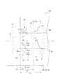
図11〜図15を参照しながら、本発明の第3実施形態について、第1実施形態と異なる点を中心に、説明する。図11〜図13は、本実施形態の金型100を示している。図14、図15は、本実施形態の樹脂部材200を示している。
第3実施形態は、金型100の軸方向一方側部分用キャビティ面121の構成と樹脂部材200の軸方向一方側部分221の構成のみが、第1実施形態と異なる。金型100の樹脂溜まり110の構成、ならびに、樹脂部材200の突起部210の構成は、第1実施形態と同様である。
[Third Embodiment]
The third embodiment of the present invention will be described with reference to FIGS. 11 to 15, focusing on the differences from the first embodiment. 11 to 13 show the mold 100 of this embodiment. 14 and 15 show the resin member 200 of this embodiment.
The third embodiment differs from the first embodiment only in the configuration of the cavity surface 121 for the axial one-side portion of the mold 100 and the configuration of the axial one-side portion 221 of the resin member 200. The configuration of the resin reservoir 110 of the mold 100 and the configuration of the protrusion 210 of the resin member 200 are the same as those of the first embodiment.

図11及び図13に示すように、本例の金型100は、トルク入力部分用キャビティ面120よりも樹脂流動方向下流側である軸方向一方側に、すなわち軸方向一方側部分用キャビティ面121に、周方向に延在するとともにキャビティCVの内側へ突出する環状凸条部130を有している。環状凸条部130は、樹脂部材200における環状凹条部230を成形するように構成されている。本例において、環状凸条部130は、周方向に連続して延在している。
この構成によれば、ゲートGから射出された溶融樹脂は、少し軸方向一方側に移動した後、環状凸条部130の手前でいったんせき止められて、樹脂の流動が乱されることにより流動がウェルド交差方向(特に周方向)へ流れるように均一化される。これにより、そこでの樹脂どうしの界面が低減するとともに、樹脂内の強化繊維Fの配向もウェルド交差方向(特に周方向)へ向くように均一化される。そして、樹脂は、環状凸条部130を乗り越えた後、流動が均一化された状態を保ったまま、軸方向一方側へと進む。よって、環状凸条部130から軸方向一方側端面用キャビティ面122までの領域で、ウェルド部Wの形成を抑制できるとともに、強化繊維Fの配向が軸方向に交差する向きひいてはウェルド交差方向になる割合を高めることができる。よって、ウェルド部Wの強度を向上できる。環状凸条部130を軸方向一方側部分用キャビティ面121に配置しているのは、上述したように、トルク入力部分用キャビティ面120の内側のキャビティCV内ではウェルド部Wが形成されにくいのに対し、軸方向一方側部分用キャビティ面121の内側のキャビティCV内ではウェルド部Wが形成されやすいからである。
同様に、図14に示すように、本例の樹脂部材200は、トルク入力部分220よりも樹脂流動方向下流側である軸方向一方側に、すなわち軸方向一方側部分221の外周面に、周方向に延在する環状凹条部230を有している。本例において、環状凹条部230は、周方向に連続して延在している。なお、樹脂部材200において、樹脂流動方向は、上述のように、樹脂部材200の有するゲートGの跡から特定できる。
As shown in FIGS. 11 and 13, the mold 100 of this example is on one side in the axial direction, which is downstream of the cavity surface 120 for the torque input portion in the resin flow direction, that is, the cavity surface 121 for the one side portion in the axial direction. In addition, it has an annular ridge 130 that extends in the circumferential direction and projects inward of the cavity CV. The annular convex portion 130 is configured to form the annular concave portion 230 of the resin member 200. In this example, the annular ridge 130 extends continuously in the circumferential direction.
According to this configuration, the molten resin injected from the gate G moves slightly to one side in the axial direction, and then is temporarily dammed in front of the annular ridge 130, and the flow is disturbed by disturbing the flow of the resin. It is made uniform so that it flows in the weld crossing direction (especially in the circumferential direction). As a result, the interface between the resins is reduced, and the orientation of the reinforcing fibers F in the resin is made uniform so as to face the weld crossing direction (particularly the circumferential direction). Then, after getting over the annular ridge 130, the resin proceeds to one side in the axial direction while maintaining a uniform flow. Therefore, the formation of the weld portion W can be suppressed in the region from the annular ridge portion 130 to the cavity surface 122 for the one side end surface in the axial direction, and the orientation of the reinforcing fibers F intersects in the axial direction, and thus in the weld intersection direction. The ratio can be increased. Therefore, the strength of the weld portion W can be improved. The reason why the annular convex portion 130 is arranged on the cavity surface 121 for one side portion in the axial direction is that the weld portion W is difficult to be formed in the cavity CV inside the cavity surface 120 for the torque input portion as described above. On the other hand, the weld portion W is likely to be formed in the cavity CV inside the cavity surface 121 for one side in the axial direction.
Similarly, as shown in FIG. 14, the resin member 200 of this example has a circumference on one side in the axial direction, which is downstream of the torque input portion 220 in the resin flow direction, that is, on the outer peripheral surface of the one side portion 221 in the axial direction. It has an annular recess 230 extending in the direction. In this example, the annular recess 230 extends continuously in the circumferential direction. In the resin member 200, the resin flow direction can be specified from the trace of the gate G of the resin member 200 as described above.

図12(a)に示すように、本例の金型100において、径方向に沿って測ったときの環状凸条部130の高さh130は、環状凸条部130の高さh130を測った位置と同じ位置で径方向に沿って測ったときのキャビティCVの厚さeの25%以上であると、好適である。これにより、環状凸条部130を十分に高くして、環状凸条部130による樹脂流動の均一化の機能を効果的に発揮させることができる。
また、本例の金型100において、径方向に沿って測ったときの環状凸条部130の高さh130は、環状凸条部130の高さh130を測った位置と同じ位置で径方向に沿って測ったときのキャビティCVの厚さeの50%以下であると、好適である。これにより、環状凸条部130によって成形される環状凹条部230の深さが深くなるのを抑制し、樹脂部材200の強度が低下するのを抑制できる。
ここで、径方向に沿って測ったときの「キャビティCVの厚さe」は、キャビティCVのなす円筒形状の周壁の厚さに相当し、本例のようにキャビティCVの内周側にめねじ用キャビティ面123が設けられている場合、めねじ用キャビティ面123の最も外周側の位置を下端とし、また、環状凸条部130の根元端面(環状凸条部130の軸方向一方側に隣接する軸方向一方側部分用キャビティ面121からの延長面)の位置を上端として、下端から上端までの距離を測定した長さである。
同様に、図15(a)に示すように、本例の樹脂部材200において、径方向に沿って測ったときの環状凹条部230の深さd230は、環状凹条部230の深さd230を測った位置と同じ位置で径方向に沿って測ったときの本体部MBの厚さe’の25%以上であると、好適である。
また、本例の樹脂部材200において、径方向に沿って測ったときの環状凹条部230の深さd230は、環状凹条部230の深さd230を測った位置と同じ位置で径方向に沿って測ったときの本体部MBの厚さe’の50%以下であると、好適である。
ここで、径方向に沿って測ったときの、「本体部MBの厚さe’」は、本体部MBのなす円筒形状の周壁の厚さに相当し、本例のように本体部MBの内周側にめねじ223が設けられている場合、めねじ223の最も外周側の位置を下端とし、また、環状凹条部230の開口端面(環状凹条部230の軸方向一方側に隣接する軸方向一方側部分221の外周面からの延長面)の位置を上端として、下端から上端までの距離を測定した長さである。
As shown in FIG. 12A, in the mold 100 of this example, the height h130 of the annular ridge 130 when measured along the radial direction is the height h130 of the annular ridge 130. It is preferable that the thickness e of the cavity CV is 25% or more when measured along the radial direction at the same position as the position. As a result, the annular ridge 130 can be made sufficiently high, and the function of uniformizing the resin flow by the annular ridge 130 can be effectively exhibited.
Further, in the mold 100 of this example, the height h130 of the annular ridge 130 when measured along the radial direction is radially the same as the position where the height h130 of the annular ridge 130 is measured. It is preferable that the thickness e of the cavity CV measured along the line is 50% or less. As a result, it is possible to prevent the depth of the annular concave portion 230 formed by the annular convex portion 130 from becoming deeper, and to prevent the strength of the resin member 200 from decreasing.
Here, the "thickness e of the cavity CV" measured along the radial direction corresponds to the thickness of the cylindrical peripheral wall formed by the cavity CV, and is fitted to the inner peripheral side of the cavity CV as in this example. When the thread cavity surface 123 is provided, the position on the outermost peripheral side of the female thread cavity surface 123 is set as the lower end, and the root end surface of the annular ridge 130 (on one side in the axial direction of the annular ridge 130). This is the length obtained by measuring the distance from the lower end to the upper end with the position of the adjacent cavity surface (extension surface 121 from the one side portion portion 121 in the axial direction) as the upper end.
Similarly, as shown in FIG. 15A, in the resin member 200 of this example, the depth d230 of the annular concave portion 230 when measured along the radial direction is the depth d230 of the annular concave portion 230. It is preferable that the thickness is 25% or more of the thickness e'of the main body MB when measured along the radial direction at the same position as the measured position.
Further, in the resin member 200 of this example, the depth d230 of the annular concave portion 230 when measured along the radial direction is in the radial direction at the same position as the position where the depth d230 of the annular concave portion 230 is measured. It is preferable that the thickness e'of the main body MB as measured along the line is 50% or less.
Here, the "thickness e'of the main body MB" when measured along the radial direction corresponds to the thickness of the cylindrical peripheral wall formed by the main body MB, and as in this example, the main body MB When the female screw 223 is provided on the inner peripheral side, the position on the outermost peripheral side of the female screw 223 is set as the lower end, and the open end surface of the annular concave portion 230 (adjacent to one side in the axial direction of the annular concave portion 230). This is the length obtained by measuring the distance from the lower end to the upper end with the position of the extension surface from the outer peripheral surface of the one side portion 221 in the axial direction as the upper end.

図12(a)に示すように、本例の金型100において、径方向に沿って測ったときの環状凸条部130の高さh130は、軸方向に沿って測ったときの環状凸条部130の幅w130よりも、大きい。これにより、環状凸条部130を高くして、環状凸条部130による樹脂流動の均一化の機能を効果的に発揮させることができるとともに、環状凸条部130によって成形される環状凹条部230の幅が広くなるのを抑制し、樹脂部材200の強度が低下するのを抑制できる。
同様に、図15(a)に示すように、本例の樹脂部材200において、所定位置で径方向に沿って測ったときの環状凹条部230の深さd230は、軸方向に沿って測ったときの環状凹条部230の幅w230よりも、大きい。
As shown in FIG. 12A, in the mold 100 of this example, the height h130 of the annular ridge 130 when measured along the radial direction is the annular ridge 130 when measured along the axial direction. It is larger than the width w130 of the portion 130. As a result, the annular ridge 130 can be raised to effectively exert the function of uniformizing the resin flow by the annular ridge 130, and the annular ridge 130 formed by the annular ridge 130. It is possible to suppress the width of the 230 from becoming wider and the strength of the resin member 200 from being lowered.
Similarly, as shown in FIG. 15A, in the resin member 200 of this example, the depth d230 of the annular concave portion 230 when measured along the radial direction at a predetermined position is measured along the axial direction. It is larger than the width w230 of the annular concave portion 230 at the time.

図11及び図12(a)に示すように、本例の金型100において、環状凸条部130は、トルク入力部分用キャビティ面120に対して、樹脂流動方向下流側である軸方向一方側に、離間した位置に配置されており、トルク入力部分用キャビティ面120と環状凸条部130との間の軸方向一方側部分用キャビティ面121によって、周方向に連続して延在するとともにキャビティCVの外側へ窪んだ環状凹条部131が構成されている。環状凹条部131は、樹脂部材200における環状凸条部231を成形するように構成されている。
この構成によれば、図12(a)に概略的に示すように、ゲートGから射出された溶融樹脂は、トルク入力部分用キャビティ面120に沿って移動してから環状凹条部131のところでいったん外周側へ移動し、それから環状凸条部130の手前でせき止められるので、仮に環状凹条部131が無い場合に比べて、環状凸条部130によって樹脂をせき止める効果が高まり、ひいては、環状凸条部130による樹脂流動の均一化の機能を効果的に発揮させることができる。
同様に、図14及び図15(a)に示すように、本例の樹脂部材200において、環状凹条部230は、トルク入力部分220に対して、樹脂流動方向下流側である軸方向一方側に、離間した位置に配置されており、トルク入力部分220と環状凹条部230との間の軸方向一方側部分221の外周面によって、周方向に連続して延在する環状凸条部231が構成されている。
As shown in FIGS. 11 and 12 (a), in the mold 100 of this example, the annular convex portion 130 is one side in the axial direction, which is the downstream side in the resin flow direction with respect to the cavity surface 120 for the torque input portion. The cavity surface 121 for the one side portion in the axial direction between the cavity surface 120 for the torque input portion and the annular ridge portion 130 extends continuously in the circumferential direction and the cavity is arranged at a separated position. An annular concave portion 131 recessed to the outside of the CV is configured. The annular concave portion 131 is configured to form the annular convex portion 231 of the resin member 200.
According to this configuration, as schematically shown in FIG. 12A, the molten resin injected from the gate G moves along the cavity surface 120 for the torque input portion and then at the annular concave portion 131. Since the resin is once moved to the outer peripheral side and then dammed in front of the annular convex portion 130, the effect of damming the resin by the annular convex portion 130 is enhanced as compared with the case where the annular concave portion 131 is not provided, and by extension, the annular convex portion. The function of uniformizing the resin flow by the strip 130 can be effectively exerted.
Similarly, as shown in FIGS. 14 and 15 (a), in the resin member 200 of this example, the annular concave portion 230 is one side in the axial direction, which is the downstream side in the resin flow direction with respect to the torque input portion 220. An annular ridge 231 that is arranged at a distance from each other and extends continuously in the circumferential direction by the outer peripheral surface of the axial one-sided portion 221 between the torque input portion 220 and the annular recess 230. Is configured.

図12(a)に示すように、本例の金型100において、軸方向に沿って測ったときの環状凹条部131の幅w131は、軸方向に沿って測ったときの環状凸条部130の幅w130以下であると、好適である。
これによって、環状凸条部130を十分にトルク入力部分220やゲートGに近い位置(軸方向他方側)に配置することにより、環状凸条部130によって樹脂をせき止める機能を効果的に発揮させることができるとともに、樹脂部材200において特に強度が要求される軸方向一方側端面122の近傍で強度が低下するのを抑制できる。
同様に、図15(a)に示すように、本例の樹脂部材200において、軸方向に沿って測ったときの環状凸条部231の幅w231は、軸方向に沿って測ったときの環状凹条部230の幅w230以下であると、好適である。
As shown in FIG. 12A, in the mold 100 of this example, the width w131 of the annular concave portion 131 when measured along the axial direction is the annular convex portion when measured along the axial direction. It is preferable that the width of 130 is w130 or less.
As a result, by arranging the annular ridge 130 at a position sufficiently close to the torque input portion 220 and the gate G (the other side in the axial direction), the function of damming the resin by the annular ridge 130 can be effectively exhibited. In addition, it is possible to suppress a decrease in strength in the vicinity of the axial one-side end surface 122, which is particularly required for strength in the resin member 200.
Similarly, as shown in FIG. 15A, in the resin member 200 of this example, the width w231 of the annular ridge portion 231 measured along the axial direction is an annular shape measured along the axial direction. It is preferable that the width of the concave portion 230 is w230 or less.

図11及び図13に示すように、本例の金型100は、軸方向一方側部分用キャビティ面121に、環状には連続せず、ウェルド延在方向(本例では軸方向)に交差する方向に延在するとともにキャビティCVの内側へ突出する、小凸条部140(凸条部)を有している。
本例では、小凸条部140は、周方向に延在している。ただし、小凸条部140は、周方向に対して非直角に交差する方向に延在していてもよい。小凸条部140は、樹脂部材200における小凹条部240を成形するように構成されている。小凸条部140の延在方向は、小凸条部140における根元端面の外縁形状を見たときの延在方向(長手方向)であるものとする。図の例では、3本の小凸条部140が、互いから間隔を空けてウェルド延在方向と交差する方向(より具体的に本例では周方向)に配列されて、小凸条部列182(凸条部列)を構成している。
この構成によれば、図11及び図12(b)に概略的に示すように、ゲートGから射出されて軸方向一方側へ移動した溶融樹脂は、小凸条部140の手前でいったんせき止められて、それを迂回するように小凸条部140の延在方向(本例では周方向)の端部へ回ってから、小凸条部140より軸方向一方側へと進む。このようにして、小凸条部140から軸方向一方側端面用キャビティ面122までの領域で、樹脂の流動を、ウェルド交差方向へ、すなわち本例では周方向へ、流れるよう促すことができる。これにより、ウェルド部Wの形状のウェルド交差方向成分(特に周方向成分)や、ゲート間位置BGPの近傍ひいてはウェルド部Wの近傍での強化繊維Fの配向のウェルド交差方向成分(特に周方向成分)を増やすことができる。よって、ウェルド部Wの強度を向上できる。また、小凸条部140は、環状には連続しないので、環状凸条部130に比べて、樹脂部材200の強度低下を抑制できる。
同様に、図14に示すように、本例の樹脂部材200は、軸方向一方側部分221の外周面に、環状には連続せず、ウェルド延在方向(本例では軸方向)に交差する方向に延在し、より具体的に本例では周方向に延在する、小凹条部240(凹条部)を有している。ただし、小凹条部240は、周方向に対して非直角に交差する方向に延在していてもよい。小凹条部240の延在方向は、小凹条部240における開口端面の外縁形状を見たときの延在方向(長手方向)であるものとする。図の例では、3本の小凹条部240が、互いから間隔を空けてウェルド延在方向と交差する方向(より具体的に本例では周方向)に配列されて、小凹条部列282(凹条部列)を構成している。
As shown in FIGS. 11 and 13, the mold 100 of this example is not annularly continuous with the cavity surface 121 for one side portion in the axial direction, but intersects the weld extending direction (axial direction in this example). It has a small ridge 140 (convex) that extends in the direction and projects inward of the cavity CV.
In this example, the small ridge portion 140 extends in the circumferential direction. However, the small ridge portion 140 may extend in a direction that intersects the circumferential direction at a non-right angle. The small ridge portion 140 is configured to form the small ridge portion 240 in the resin member 200. The extending direction of the small ridge portion 140 is assumed to be the extending direction (longitudinal direction) when the outer edge shape of the root end surface of the small ridge portion 140 is viewed. In the example of the figure, the three small ridges 140 are arranged in the direction intersecting the weld extending direction (more specifically, the circumferential direction in this example) at intervals from each other, and the small ridges are arranged. It constitutes 182 (convex row).
According to this configuration, as schematically shown in FIGS. 11 and 12 (b), the molten resin ejected from the gate G and moved to one side in the axial direction is temporarily dammed in front of the small ridge portion 140. Then, it turns to the end of the small ridge 140 in the extending direction (circumferential direction in this example) so as to bypass it, and then proceeds from the small ridge 140 to one side in the axial direction. In this way, in the region from the small ridge portion 140 to the cavity surface 122 for the one side end surface in the axial direction, the flow of the resin can be encouraged to flow in the weld crossing direction, that is, in the circumferential direction in this example. As a result, the weld crossing direction component (particularly the circumferential component) in the shape of the weld portion W and the weld crossing direction component (particularly the circumferential component) of the orientation of the reinforcing fibers F in the vicinity of the intergate position BGP and in the vicinity of the weld portion W. ) Can be increased. Therefore, the strength of the weld portion W can be improved. Further, since the small ridges 140 are not continuous in an annular shape, it is possible to suppress a decrease in the strength of the resin member 200 as compared with the annular ridges 130.
Similarly, as shown in FIG. 14, the resin member 200 of this example does not form an annular shape and intersects the outer peripheral surface of the axial one-side portion 221 in the weld extending direction (axial direction in this example). It has a small recess 240 (concave portion) that extends in the direction, and more specifically, extends in the circumferential direction in this example. However, the small recessed portion 240 may extend in a direction that intersects the circumferential direction at a non-right angle. The extending direction of the small concave portion 240 is assumed to be the extending direction (longitudinal direction) when the outer edge shape of the opening end surface of the small concave portion 240 is viewed. In the example of the figure, the three small recesses 240 are arranged in a direction (more specifically, the circumferential direction in this example) that intersects the weld extending direction at intervals from each other, and the small recesses are arranged in a row. It constitutes 282 (concave row).

図11の金型100において、各小凸条部140は、キャビティCVの樹脂流動方向下流側(軸方向一方側)の端部近傍に配置されている。ここで、「キャビティCVの樹脂流動方向下流側(軸方向一方側)の端部近傍」とは、ゲートGとキャビティCVの軸方向一方側端(軸方向一方側端面用キャビティ面122)との間の軸方向距離LGの35%の距離にわたって延在する、最も樹脂流動方向下流側(軸方向一方側)の領域を指す。より具体的に、本例の各小凸条部140の樹脂流動方向上流側(軸方向他方側)の端縁部140ceは、ゲートGとキャビティCVの軸方向一方側端(軸方向一方側端面用キャビティ面122)との間の軸方向距離LGの23%の距離L1(L1=0.23×LG)だけ、キャビティCVの樹脂流動方向下流側の端122から樹脂流動方向上流側へ離れた、軸方向位置ap1よりも、樹脂流動方向下流側に配置されると、好適である。また、本例の各小凸条部140の樹脂流動方向上流側(軸方向他方側)の端縁部140ceは、軸方向一方側部分用キャビティ面121の軸方向全長L121の37%の距離L1(L1=0.37×L121)だけ、キャビティCVの樹脂流動方向下流側の端122から樹脂流動方向上流側へ離れた、軸方向位置ap1よりも、樹脂流動方向下流側に配置されると、好適である。
これにより、樹脂部材200の強度をさほど低下させずに、特にウェルド部Wが形成されやすく領域、また、特に高い強度が要求される領域である、樹脂流動方向下流側(軸方向一方側)の端部近傍で、樹脂の流動を積極的にウェルド交差方向(周方向)に向けて、ウェルド部Wの強度を向上できる。
同様に、図14の樹脂部材200において、各小凹条部240は、本体部MBの樹脂流動方向下流側(軸方向一方側)の端部近傍に配置されている。ここで、「本体部MBの樹脂流動方向下流側(軸方向一方側)の端部近傍」とは、ゲートGと本体部MBの軸方向一方側端(軸方向一方側端面222)との間の軸方向距離LGの35%の距離にわたって延在する、最も樹脂流動方向下流側(軸方向一方側)の領域を指す。より具体的に、本例の各小凹条部240の軸方向他方側の端縁部240ceは、ゲートGと本体部MBの軸方向一方側端(軸方向一方側端面222)との間の軸方向距離LG’の23%の距離L1’(L1’=0.23×LG’)だけ、本体部MBの樹脂流動方向下流側の端222から樹脂流動方向上流側へ離れた、軸方向位置ap1’よりも、樹脂流動方向下流側に配置されると、好適である。また、本例の各小凹条部240の軸方向他方側の端縁部240ceは、軸方向一方側部分221の軸方向全長L221の37%の距離L1’(L1’=0.37×L221)だけ、本体部MBの樹脂流動方向下流側の端から樹脂流動方向上流側へ離れた、軸方向位置ap1’よりも、樹脂流動方向下流側に配置されると、好適である。
In the mold 100 of FIG. 11, each small ridge portion 140 is arranged near the end portion of the cavity CV on the downstream side (one side in the axial direction) in the resin flow direction. Here, "near the end of the cavity CV on the downstream side in the resin flow direction (one side in the axial direction)" means the gate G and the one side end in the axial direction of the cavity CV (cavity surface 122 for one end surface in the axial direction). Axial distance between them Refers to the region most downstream in the resin flow direction (one side in the axial direction) extending over a distance of 35% of the LG. More specifically, the edge portion 140ce on the upstream side (the other side in the axial direction) of each small ridge portion 140 in this example is the one side end surface in the axial direction (one side end surface in the axial direction) of the gate G and the cavity CV. The distance L1 (L1 = 0.23 × LG) of 23% of the axial distance LG from the cavity surface 122) is separated from the end 122 on the downstream side in the resin flow direction of the cavity CV toward the upstream side in the resin flow direction. , It is preferable that the device is arranged on the downstream side in the resin flow direction with respect to the axial position ap1. Further, the edge portion 140ce on the upstream side (the other side in the axial direction) of each small ridge portion 140 in the resin flow direction of this example has a distance L1 of 37% of the total length L121 in the axial direction of the cavity surface 121 for one side portion in the axial direction. When only (L1 = 0.37 × L121) is arranged on the downstream side in the resin flow direction from the axial position ap1 which is separated from the end 122 on the downstream side in the resin flow direction of the cavity CV to the upstream side in the resin flow direction, Suitable.
As a result, the strength of the resin member 200 is not significantly reduced, and the weld portion W is particularly likely to be formed, and the region on the downstream side in the resin flow direction (one side in the axial direction), which is a region where particularly high strength is required. The strength of the weld portion W can be improved by positively directing the flow of the resin in the weld crossing direction (circumferential direction) in the vicinity of the end portion.
Similarly, in the resin member 200 of FIG. 14, each small concave groove portion 240 is arranged near the end portion of the main body portion MB on the downstream side (one side in the axial direction) in the resin flow direction. Here, "near the end of the main body MB on the downstream side in the resin flow direction (one side in the axial direction)" is between the gate G and one side end in the axial direction (one side end surface 222 in the axial direction) of the main body MB. Axial distance Refers to the region most downstream in the resin flow direction (one side in the axial direction) extending over a distance of 35% of the LG. More specifically, the edge portion 240ce on the other side in the axial direction of each of the small concave portions 240 in this example is between the gate G and the one side end in the axial direction (one side end surface 222 in the axial direction) of the main body portion MB. Axial position separated from the end 222 on the downstream side in the resin flow direction of the main body MB by the distance L1'(L1'= 0.23 x LG'), which is 23% of the axial distance LG', to the upstream side in the resin flow direction. It is preferable that it is arranged on the downstream side in the resin flow direction with respect to ap1'. Further, the edge portion 240ce on the other side in the axial direction of each of the small concave portions 240 in this example has a distance L1'(L1'= 0.37 x L221) that is 37% of the total length L221 in the axial direction of the one side portion 221 in the axial direction. ), It is preferable that the main body MB is arranged on the downstream side in the resin flow direction from the axial position ap1', which is separated from the end on the downstream side in the resin flow direction to the upstream side in the resin flow direction.

図11の金型100において、小凸条部140は、ゲート間位置BGP(ひいてはウェルド部W)とは重複しない位置(周方向位置)に配置されており、すなわち、ゲート間位置BGP(ひいてはウェルド部W)から、ウェルド延在方向と交差する方向(より具体的に本例では周方向)に離間している。具体的には、小凸条部140は、ゲート位置GPと重複する位置(周方向位置)に配置されている。
ゲート間位置BGP(ひいてはウェルド部W)は、もともと樹脂部材200において最も強度が低下しやすいところであることから、そこに小凸条部140を配置しないようにし、ひいてはそこに小凹条部240が成形されないようにすることで、樹脂部材200の強度低下を抑制できる。また、逆に、ゲート位置GPは、もともと樹脂部材200において最も強度が高くなるところであることから、そこに小凸条部140を配置し、ひいてはそこに小凹条部240を成形させることで、樹脂部材200の強度低下を極力抑制できる。
同様に、図14の樹脂部材200において、小凹条部240は、ゲート間位置BGP(ひいてはウェルド部W)とは重複しない位置(周方向位置)に配置されており、すなわち、ゲート間位置BGP(ひいてはウェルド部W)から、ウェルド延在方向と交差する方向(より具体的に本例では周方向)に離間している。具体的には、小凹条部240は、ゲート位置GPと重複する位置(周方向位置)に配置されている。なお、樹脂部材200において、ゲート位置GPやゲート間位置BGPは、上述のように、ゲートGの跡から特定できる。
In the mold 100 of FIG. 11, the small ridge portion 140 is arranged at a position (circumferential direction position) that does not overlap with the inter-gate position BGP (and thus the weld portion W), that is, the inter-gate position BGP (and thus the weld). It is separated from the portion W) in a direction intersecting the weld extending direction (more specifically, in the circumferential direction in this example). Specifically, the small ridge portion 140 is arranged at a position (circumferential direction position) overlapping the gate position GP.
Since the inter-gate position BGP (and thus the weld portion W) is originally the place where the strength of the resin member 200 is most likely to decrease, the small ridge portion 140 is not arranged there, and the small concave portion 240 is formed there. By preventing the resin member 200 from being molded, it is possible to suppress a decrease in the strength of the resin member 200. On the contrary, since the gate position GP is originally the place where the strength of the resin member 200 is the highest, the small ridge portion 140 is arranged there, and the small dent portion 240 is formed there. The decrease in strength of the resin member 200 can be suppressed as much as possible.
Similarly, in the resin member 200 of FIG. 14, the small concave groove portion 240 is arranged at a position (circumferential direction position) that does not overlap with the intergate position BGP (and thus the weld portion W), that is, the intergate position BGP. It is separated from (by extension, the weld portion W) in a direction intersecting the weld extension direction (more specifically, in the circumferential direction in this example). Specifically, the small concave groove portion 240 is arranged at a position (circumferential direction position) overlapping the gate position GP. In the resin member 200, the gate position GP and the inter-gate position BGP can be specified from the traces of the gate G as described above.

図11の金型100において、小凸条部140は、その根元端面の外縁のうち、小突条部140の延在方向(本例では周方向)の少なくとも一方側(図の例では両側)の端縁部140ae、140beが、ウェルド延在方向(本例では軸方向)に対して非直角に交差する方向に延在しているとともに、ウェルド延在方向に垂直な方向(本例では周方向)に対して非直角に交差する方向に延在している。
この構成によれば、図11及び図12(b)に概略的に示すように、溶融樹脂が小凸条部140の手前でいったんせき止められて、それを迂回するように小凸条部140の延在方向(本例では周方向)の端部へ回ってから、小凸条部140より軸方向一方側へと進もうとする際、小凸条部140の延在方向端側の壁面140a、140bによって、樹脂の流動を、ウェルド延在方向に交差する方向へ、すなわち本例では周方向へ、流れるように効果的に促すことができる。これにより、ウェルド部Wの形状のウェルド交差方向成分(周方向成分)や、ゲート間位置BGPの近傍ひいてはウェルド部Wの近傍での強化繊維Fの配向のウェルド交差方向成分(周方向成分)を増やすことができる。よって、ウェルド部Wの強度を向上できる。
同様に、図14の樹脂部材200において、小凹条部240は、その開口端面の外縁のうち、小凹条部240の延在方向(本例では周方向)の少なくとも一方側(図の例では両側)の端縁部240ae、240beが、ウェルド延在方向(本例では軸方向)に対して非直角に交差する方向に延在しているとともに、ウェルド延在方向に垂直な方向(本例では周方向)に対して非直角に交差する方向に延在している。
In the mold 100 of FIG. 11, the small ridge portion 140 is at least one side (both sides in the example of the figure) of the outer edge of the root end surface of the small ridge portion 140 in the extending direction (circumferential direction in this example). The edge portions 140ae and 140be extend in a direction that intersects the weld extending direction (axial direction in this example) at a non-right angle, and are perpendicular to the weld extending direction (circumferential in this example). It extends in a direction that intersects at a non-right angle to the direction).
According to this configuration, as schematically shown in FIGS. 11 and 12 (b), the molten resin is once dammed in front of the small ridge 140, and the small ridge 140 is bypassed. When trying to move from the small ridge 140 to one side in the axial direction after turning to the end in the extending direction (circumferential direction in this example), the wall surface 140a on the end side in the extending direction of the small ridge 140 , 140b can effectively encourage the flow of the resin to flow in the direction intersecting the weld extending direction, that is, in the circumferential direction in this example. As a result, the weld crossing direction component (circumferential direction component) in the shape of the weld portion W and the weld crossing direction component (circumferential direction component) of the orientation of the reinforcing fibers F in the vicinity of the intergate position BGP and in the vicinity of the weld portion W can be obtained. Can be increased. Therefore, the strength of the weld portion W can be improved.
Similarly, in the resin member 200 of FIG. 14, the small concave groove portion 240 is at least one side (in the example of the figure) of the outer edge of the open end surface of the small concave groove portion 240 in the extending direction (circumferential direction in this example). The edge portions 240ae and 240be on both sides extend in a direction that intersects the weld extending direction (axial direction in this example) at a non-right angle, and are perpendicular to the weld extending direction (book). In the example, it extends in a direction that intersects at a non-right angle to the circumferential direction).

図11の金型100において、小凸条部140は、その根元端面の外縁が平行四辺形状をなしている。そして、小凸条部140は、その根元端面の外縁のうち、小凸条部140の延在方向(本例では周方向)の両側の端縁部140ae、140beが、それぞれ、ウェルド延在方向(本例では軸方向)の一方側に向かうにつれて、ウェルド延在方向に垂直な方向(本例では周方向)の同じ側に向かうように、直線状に延在している。
この構成によれば、小凸条部140から軸方向一方側で、樹脂の流動が、ウェルド交差方向の同じ側、すなわち本例では周方向の同じ側へ、循環するように効果的に促すことができる。
同様に、図14の樹脂部材200において、小凹条部240は、その開口端面の外縁が平行四辺形状をなしている。そして、小凹条部240は、その開口端面の外縁のうち、小凹条部240の延在方向(本例では周方向)の両側の端縁部240ae、240beが、それぞれ、ウェルド延在方向(本例では軸方向)の一方側に向かうにつれて、ウェルド延在方向に垂直な方向(本例では周方向)の同じ側に向かうように、直線状に延在している。
In the mold 100 of FIG. 11, the outer edge of the root end surface of the small ridge portion 140 has a parallel four-sided shape. Of the outer edges of the root end faces of the small ridges 140, the edge portions 140ae and 140be on both sides of the small ridges 140 in the extending direction (circumferential direction in this example) are weld extending directions, respectively. As it goes to one side (axial direction in this example), it extends linearly so as to go to the same side in the direction perpendicular to the weld extending direction (circumferential direction in this example).
According to this configuration, the flow of the resin is effectively promoted to circulate from the small ridge 140 on one side in the axial direction to the same side in the weld crossing direction, that is, the same side in the circumferential direction in this example. Can be done.
Similarly, in the resin member 200 of FIG. 14, the outer edge of the opening end surface of the small concave groove portion 240 has a parallel four-sided shape. Of the outer edges of the open end faces of the small recesses 240, the edge portions 240ae and 240be on both sides of the small recesses 240 in the extending direction (circumferential direction in this example) are weld extending directions, respectively. As it goes to one side (axial direction in this example), it extends linearly so as to go to the same side in the direction perpendicular to the weld extending direction (circumferential direction in this example).

図12(b)及び図13に示すように、本例の金型100において、小凸条部140は、その延在方向(本例では周方向)の少なくとも一方側(図の例では両側)の壁面140a、140bが、小凸条部140の延在方向のそれぞれの対応する側に向かうにつれて、連続的又は段階的に、小凸条部140の根元端面に向かうように(すなわち小凸条部140の高さが減少するように)、延在している。より具体的に、本例では、小凸条部140は、その延在方向(本例では周方向)の少なくとも一方側(図の例では両側)の壁面140a、140bが、小凸条部140の延在方向のそれぞれの対応する側に向かうにつれて、連続的に、小凸条部140の根元端面に向かうように(すなわち小凸条部140の高さが減少するように)、まっすぐに延在(傾斜)しており、すなわち、テーパ状に構成されている。
この構成によれば、仮に例えば小凸条部140の延在方向(本例では周方向)の両側の壁面140a、140bが小凸条部140の根元端面に垂直である場合に比べて、小凸条部140による、樹脂の流動を、ウェルド交差方向の同じ側、すなわち本例では周方向の同じ側へ流れるよう促す機能を、より効果的に発揮させられるとともに、成形品である樹脂部材200の強度をより高めることができ、また、離型時において金型100の小凸条部140を樹脂部材200の小凹条部240から抜き易くなる。
同様に、図14の樹脂部材200において、小凹条部240は、その延在方向(本例では周方向)の少なくとも一方側(図の例では両側)の壁面240a、240bが、小凹条部240の延在方向のそれぞれの対応する側に向かうにつれて、連続的又は段階的に、小凹条部240の開口端面に向かうように(すなわち小凹条部240の深さが減少するように)、延在している。より具体的に、本例では、小凹条部240は、その延在方向(本例では周方向)の少なくとも一方側(図の例では両側)の壁面240a、240bが、小凹条部240の延在方向のそれぞれの対応する側に向かうにつれて、連続的に、小凹条部240の開口端面に向かうように(すなわち小凹条部240の深さが減少するように)、まっすぐに延在(傾斜)しており、すなわち、テーパ状に構成されている。
As shown in FIGS. 12B and 13, in the mold 100 of this example, the small ridge portion 140 is at least one side (both sides in the example of FIG.) of its extending direction (circumferential direction in this example). As the wall surfaces 140a and 140b of the surface toward the corresponding sides in the extending direction of the small ridge 140, continuously or stepwise toward the root end surface of the small ridge 140 (that is, the small ridge 140). It is protracted (so that the height of the portion 140 is reduced). More specifically, in this example, the small ridges 140 have wall surfaces 140a and 140b on at least one side (both sides in the example of the figure) in the extending direction (circumferential direction in this example). As it goes toward each corresponding side of the extending direction, it extends straight toward the root end face of the small ridge 140 (that is, the height of the small ridge 140 decreases). It is present (inclined), that is, it is configured in a tapered shape.
According to this configuration, for example, the wall surfaces 140a and 140b on both sides in the extending direction (circumferential direction in this example) of the small ridge portion 140 are smaller than the case where they are perpendicular to the root end surface of the small ridge portion 140. The function of promoting the flow of the resin by the ridges 140 to the same side in the weld crossing direction, that is, to the same side in the circumferential direction in this example can be more effectively exhibited, and the resin member 200 which is a molded product. In addition, the small ridge portion 140 of the mold 100 can be easily pulled out from the small ridge portion 240 of the resin member 200 at the time of mold release.
Similarly, in the resin member 200 of FIG. 14, the small recesses 240 have the wall surfaces 240a and 240b on at least one side (both sides in the example of the figure) of the extending direction (circumferential direction in this example). Toward the respective corresponding sides of the extending direction of the portion 240, continuously or stepwise, towards the open end face of the minor recess 240 (ie, the depth of the minor recess 240 decreases). ), It is postponed. More specifically, in this example, the small recesses 240 have wall surfaces 240a and 240b on at least one side (both sides in the example of the figure) in the extending direction (circumferential direction in this example). Continuously extending straight toward the open end face of the small recess 240 (ie, reducing the depth of the small recess 240) towards each corresponding side of the extending direction of the It is present (inclined), that is, it is configured in a tapered shape.

図12(b)に示すように、本例の金型100において、小凸条部140の高さが最大となる位置で小凸条部140の根元端面に垂直な方向(径方向)に沿って測ったときの小凸条部140の高さh140は、当該位置で小凸条部140の根元端面に垂直な方向(径方向)に沿って測ったときのキャビティCVの厚さeの25%以上であると、好適である。これにより、小凸条部140を十分に高くして、小凸条部140による樹脂流動の案内機能を効果的に発揮させることができる。
また、本例の金型100において、小凸条部140の高さが最大となる位置で小凸条部140の根元端面に垂直な方向(径方向)に沿って測ったときの小凸条部140の高さh140は、当該位置で小凸条部140の根元端面に垂直な方向(径方向)に沿って測ったときのキャビティCVの厚さeの50%以下であると、好適である。これにより、小凸条部140によって成形される小凹条部240の深さが深くなるのを抑制し、樹脂部材200の強度が低下するのを抑制できる。
同様に、図15(b)に示すように、本例の樹脂部材200において、小凹条部240の深さが最大となる位置で小凹条部240の開口端面に垂直な方向(径方向)に沿って測ったときの、小凹条部240の深さd240は、当該位置で小凹条部240の開口端面に垂直な方向(径方向)に沿って測ったときの本体部MBの厚さe’の25%以上であると、好適である。
また、本例の樹脂部材200において、小凹条部240の深さが最大となる位置で小凹条部240の開口端面に垂直な方向(径方向)に沿って測ったときの、小凹条部240の深さd240は、当該位置で小凹条部240の開口端面に垂直な方向(径方向)に沿って測ったときの本体部MBの厚さe’の50%以下であると、好適である。
As shown in FIG. 12B, in the mold 100 of this example, at the position where the height of the small ridge portion 140 is maximized, along the direction (diameter direction) perpendicular to the root end surface of the small ridge portion 140. The height h140 of the small ridge portion 140 as measured is 25 of the thickness e of the cavity CV when measured along the direction (diameter direction) perpendicular to the root end surface of the small ridge portion 140 at that position. % Or more is preferable. As a result, the small ridge 140 can be made sufficiently high so that the resin flow guidance function of the small ridge 140 can be effectively exerted.
Further, in the mold 100 of this example, the small ridges are measured along the direction (diameter direction) perpendicular to the root end surface of the small ridges 140 at the position where the height of the small ridges 140 is maximum. It is preferable that the height h140 of the portion 140 is 50% or less of the thickness e of the cavity CV when measured along the direction (diameter direction) perpendicular to the root end surface of the small convex portion 140 at that position. is there. As a result, it is possible to suppress the depth of the small concave groove portion 240 formed by the small convex groove portion 140 from becoming deep, and to prevent the strength of the resin member 200 from decreasing.
Similarly, as shown in FIG. 15B, in the resin member 200 of this example, the direction (diameter direction) perpendicular to the opening end surface of the small concave portion 240 at the position where the depth of the small concave portion 240 is maximized. ), The depth d240 of the small concave portion 240 is the main body MB when measured along the direction (diameter direction) perpendicular to the opening end face of the small concave portion 240 at that position. It is preferable that the thickness is 25% or more of e'.
Further, in the resin member 200 of this example, the small recess is measured along the direction (diameter direction) perpendicular to the opening end surface of the small recess 240 at the position where the depth of the small recess 240 is maximized. The depth d240 of the strip 240 is 50% or less of the thickness e'of the main body MB when measured along the direction (diameter direction) perpendicular to the opening end face of the small recess 240 at the position. , Suitable.

なお、金型100は、図11の例に限られず、環状凸部130及び小凸条部140のそれぞれを、軸方向一方側部分用キャビティ面121における任意の位置に、任意の本数(1本又は複数本)だけ有してよい。また、金型100は、環状凸部130及び小凸条部140のうち一方のみを有してもよい。また、金型100は、環状凸条部130を2本以上有してもよいが、成形品である樹脂部材200の強度確保の観点からは、環状凸条部130を1本のみ有するほうがよい。
同様に、樹脂部材200は、図14の例に限られず、環状凹部230及び小凹条部240のそれぞれを、軸方向一方側部分221の外周面における任意の位置に、任意の本数(1本又は複数本)だけ有してよい。また、樹脂部材200は、環状凹部230及び小凹条部240のうち一方のみを有してもよい。また、樹脂部材200は、環状凹条部230を2本以上有してもよいが、環状凹条部230を1本のみ有するほうがよい。
The mold 100 is not limited to the example of FIG. 11, and each of the annular convex portion 130 and the small convex portion 140 is placed at an arbitrary position on the cavity surface 121 for one side portion in the axial direction (one). Or you may have only a plurality of). Further, the mold 100 may have only one of the annular convex portion 130 and the small convex portion 140. Further, the mold 100 may have two or more annular ridges 130, but from the viewpoint of ensuring the strength of the resin member 200 which is a molded product, it is preferable to have only one annular ridge 130. ..
Similarly, the resin member 200 is not limited to the example of FIG. 14, and each of the annular recess 230 and the small recess 240 is arranged at an arbitrary position on the outer peripheral surface of the axial one-side portion 221 (one). Or you may have only multiple). Further, the resin member 200 may have only one of the annular recess 230 and the small recess 240. Further, the resin member 200 may have two or more annular concave portions 230, but it is preferable that the resin member 200 has only one annular concave portion 230.

〔第4実施形態〕
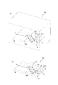
図16〜図20を参照しながら、本発明の第4実施形態について、第3実施形態と異なる点を中心に、説明する。図16〜図18は、本実施形態の金型100を示している。図19、図20は、本実施形態の樹脂部材200を示している。
第4実施形態は、金型100の軸方向一方側部分用キャビティ面121の構成と樹脂部材200の軸方向一方側部分221の構成のみが、第3実施形態と異なる。金型100の樹脂溜まり110の構成、ならびに、樹脂部材200の突起部210の構成は、第1実施形態と同様である。
[Fourth Embodiment]
The fourth embodiment of the present invention will be described with reference to FIGS. 16 to 20, focusing on the differences from the third embodiment. 16 to 18 show the mold 100 of this embodiment. 19 and 20 show the resin member 200 of this embodiment.
The fourth embodiment differs from the third embodiment only in the configuration of the cavity surface 121 for the axial one-side portion of the mold 100 and the configuration of the axial one-side portion 221 of the resin member 200. The configuration of the resin reservoir 110 of the mold 100 and the configuration of the protrusion 210 of the resin member 200 are the same as those of the first embodiment.

図16及び図18に示すように、本例の金型100は、第3実施形態(図11)と同様に、軸方向一方側部分用キャビティ面121に、複数の小凸条部140(小凸条部150、151、160、161)を有している。以下では、小凸条部150、151、160、161どうしを区別しないときに、これらの個々を「小凸条部140」とよぶ。各小凸条部140は、それぞれ、環状には連続せず、ウェルド延在方向(本例では軸方向)に交差する方向に、より具体的に本例では周方向に、延在している。ただし、小凸条部140は、それぞれ、周方向に対して非直角に交差する方向に延在していてもよい。小凸条部140(小凸条部150、151、160、161)は、樹脂部材200における小凹条部240(小凹条部250、251、260、261)を成形するように構成されている。小凸条部140の延在方向は、小凸条部140における根元端面の外縁形状を見たときの延在方向(長手方向)であるものとする。
そして、本例の金型100は、複数の小凸条部140が、ウェルド延在方向に交差する方向に互いから間隔を空けて配置されているとともに、ウェルド延在方向に互いから間隔を空けて配置されている。具体的には、金型100は、互いから間隔を空けてウェルド延在方向に交差する方向(本例では周方向)に配列された複数(図の例では6本)の小凸条部151、161から構成された小凸条部列181と、小凸条部列181より樹脂流動方向下流側である軸方向一方側に配置され、互いから間隔を空けてウェルド延在方向に交差する方向(本例では周方向)に配列された複数(図の例では6本)の小凸条部150、160から構成された小凸条部列180とを、有している。また、これらの小凸条部列180、181どうしの間の軸方向一方側部分用キャビティ面121によって、周方向に連続して延在する環状凹条部170が構成されている。環状凹条部170は、キャビティCVの外側へ窪んでおり、樹脂部材200における環状凸条部270を成形するように構成されている。
この構成によれば、図16に概略的に示すように、ゲートGから射出されて軸方向一方側へ移動した溶融樹脂は、上流側の小凸条部列181の小凸条部151、161の手前でいったんせき止められて、それらを迂回するように小凸条部151、161の延在方向(本例では周方向)の端部へ回ってから、小凸条部151、161より軸方向一方側へと進む。つぎに、樹脂は、下流側の小凸条部列180の小凸条部150、160手前でいったんせき止められて、それらを迂回するように環状凹条部170を通ってから、小凸条部150、160の延在方向(本例では周方向)の端部へ回って、軸方向一方側へ進む。このようにして、溶融樹脂は、各小凸条部140の延在方向の端部の脇を通過する際や、環状凹条部170を通る際に、ウェルド延在方向に交差する方向(本例では周方向)へ流れるよう促される。これにより、ウェルド部Wの形状のウェルド交差方向成分(周方向成分)や、ゲート間位置BGPの近傍ひいてはウェルド部Wの近傍での強化繊維Fの配向のウェルド交差方向成分(周方向成分)を増やすことができる。よって、ウェルド部Wの強度を向上できる。また、上流側の小凸条部列181の小凸条部151、161どうし、下流側の小凸条部列180の小凸条部150、160どうしは、互いに連通していないので、例えば環状凸条部130(図11)を2本設ける場合に比べて、成形品である樹脂部材200の強度低下を抑制できる。また、小凸条部列180、181どうしの間に、環状凸条部270を成形する環状凹条部170があることにより、その分、成形品である樹脂部材200の強度を向上できる。
同様に、図19に示すように、本例の樹脂部材200は、第3実施形態(図14)と同様に、軸方向一方側部分221の外周面に、複数の小凹条部240(小凹条部250、251、260、261)を有している。以下では、小凹条部250、251、260、261どうしを区別しないときに、これらの個々を「小凹条部240」とよぶ。各小凹条部240は、それぞれ、環状には連続せず、ウェルド延在方向(本例では軸方向)に交差する方向に、より具体的に本例では周方向に、延在している。ただし、小凹条部240は、それぞれ周方向に対して非直角に交差する方向に延在していてもよい。小凹条部240の延在方向は、小凹条部240における開口端面の外縁形状を見たときの延在方向(長手方向)であるものとする。
そして、本例の樹脂部材200は、複数の小凹条部240が、ウェルド延在方向に交差する方向に互いから間隔を空けて配置されているとともに、ウェルド延在方向に互いから間隔を空けて配置されている。具体的には、樹脂部材200は、互いから間隔を空けてウェルド延在方向に交差する方向(本例では周方向)に配列された複数(図の例では6本)の小凹条部251、261から構成された小凹条部列281と、小凹条部列281より樹脂流動方向下流側である軸方向一方側に配置され、互いから間隔を空けてウェルド延在方向に交差する方向(本例では周方向)に配列された複数(図の例では6本)の小凹条部250、260から構成された小凹条部列280とを、有している。また、これらの小凹条部列280、281どうしの間の軸方向一方側部分221の外周面によって、周方向に連続して延在する環状凸条部270が構成されている。
As shown in FIGS. 16 and 18, the mold 100 of this example has a plurality of small ridges 140 (small) on the cavity surface 121 for one side portion in the axial direction, as in the third embodiment (FIG. 11). It has ridges 150, 151, 160, 161). In the following, when the small ridges 150, 151, 160, and 161 are not distinguished from each other, these individual parts are referred to as "small ridges 140". Each of the small ridges 140 is not continuous in an annular shape, but extends in a direction intersecting the weld extending direction (axial direction in this example), and more specifically in the circumferential direction in this example. .. However, the small ridges 140 may extend in directions that intersect at non-right angles to the circumferential direction. The small ridges 140 (small ridges 150, 151, 160, 161) are configured to form the small ridges 240 (small ridges 250, 251, 260, 261) in the resin member 200. There is. The extending direction of the small ridge portion 140 is assumed to be the extending direction (longitudinal direction) when the outer edge shape of the root end surface of the small ridge portion 140 is viewed.
In the mold 100 of this example, the plurality of small convex stripes 140 are arranged at intervals from each other in the direction in which they intersect in the weld extending direction, and at the same time, they are spaced from each other in the weld extending direction. Are arranged. Specifically, the mold 100 has a plurality of (six in the example of the figure) small convex stripes 151 arranged in a direction (circumferential direction in this example) intersecting the weld extending direction at intervals from each other. , 161 are arranged on one side in the axial direction, which is the downstream side in the resin flow direction from the small convex row portion row 181 and the small convex row portion row 181 and intersect in the weld extending direction at intervals from each other. It has a plurality of small ridges (six in the example of the figure) arranged in the circumferential direction (in this example), and a row of small ridges 180 composed of 150 and 160. Further, the annular concave portion 170 extending continuously in the circumferential direction is formed by the cavity surface 121 for one side portion in the axial direction between the small convex groove portion rows 180 and 181. The annular ridge 170 is recessed to the outside of the cavity CV and is configured to form the annular ridge 270 of the resin member 200.
According to this configuration, as schematically shown in FIG. 16, the molten resin ejected from the gate G and moved to one side in the axial direction is the small ridge portions 151, 161 of the small ridge portion row 181 on the upstream side. Once dammed in front of, turn to the end of the small ridges 151 and 161 in the extending direction (circumferential direction in this example) so as to bypass them, and then axially from the small ridges 151 and 161. Proceed to one side. Next, the resin is once dammed in front of the small ridges 150 and 160 of the small ridge row 180 on the downstream side, passes through the annular ridge 170 so as to bypass them, and then the small ridges. It turns to the end of the extending direction (circumferential direction in this example) of 150 and 160, and proceeds to one side in the axial direction. In this way, the molten resin intersects the weld extending direction when passing by the side of the end portion of each small convex portion 140 in the extending direction or when passing through the annular concave portion 170 (this). In the example, it is prompted to flow in the circumferential direction). As a result, the weld crossing direction component (circumferential direction component) in the shape of the weld portion W and the weld crossing direction component (circumferential direction component) of the orientation of the reinforcing fibers F in the vicinity of the intergate position BGP and in the vicinity of the weld portion W can be obtained. Can be increased. Therefore, the strength of the weld portion W can be improved. Further, the small ridges 151 and 161 of the small ridge row 181 on the upstream side and the small ridges 150 and 160 of the small ridge row 180 on the downstream side do not communicate with each other. Compared with the case where two convex portions 130 (FIG. 11) are provided, it is possible to suppress a decrease in strength of the resin member 200 which is a molded product. Further, since the annular concave portion 170 for molding the annular convex portion 270 is provided between the small convex portion rows 180 and 181, the strength of the resin member 200 which is a molded product can be improved accordingly.
Similarly, as shown in FIG. 19, the resin member 200 of this example has a plurality of small recesses 240 (small) on the outer peripheral surface of the axial one-sided portion 221 as in the third embodiment (FIG. 14). It has recesses 250, 251 and 260, 261). In the following, when the small recesses 250, 251, 260, and 261 are not distinguished from each other, each of these is referred to as a "small recess 240". Each of the small recesses 240 is not continuous in an annular shape, but extends in a direction intersecting the weld extending direction (axial direction in this example), and more specifically in the circumferential direction in this example. .. However, the small recesses 240 may extend in directions that intersect at non-right angles to the circumferential direction. The extending direction of the small concave portion 240 is assumed to be the extending direction (longitudinal direction) when the outer edge shape of the opening end surface of the small concave portion 240 is viewed.
In the resin member 200 of this example, the plurality of small recesses 240 are arranged at intervals from each other in the direction in which they intersect in the weld extending direction, and are spaced from each other in the weld extending direction. Are arranged. Specifically, the resin members 200 are arranged in a direction in which they intersect with each other in the weld extending direction (circumferential direction in this example) at intervals from each other (six in the example of the figure). , 261 are arranged on one side in the axial direction, which is the downstream side in the resin flow direction from the small concave row portion row 281 and the small concave row portion row 281 are spaced apart from each other and intersect in the weld extending direction. It has a plurality of (six in the example of the figure) small recesses 250 and 260 arranged in the circumferential direction (in this example), and a row of small recesses 280. Further, the outer peripheral surface of the axial one-sided portion 221 between the small concave groove portions 280 and 281 constitutes an annular convex groove portion 270 extending continuously in the circumferential direction.

図16の金型100では、ウェルド延在方向(本例では軸方向)に互いに隣接する一対の小凸条部150、151どうし、160、161どうしが、ウェルド延在方向に重複していながらも、ウェルド延在方向に垂直な方向(本例では周方向)にずれて配置されている。
この構成によれば、下流側の小凸条部列180の小凸条部150、160によって、上流側の小凸条部列181を通過した溶融樹脂を、より効果的にせき止めて、そのまま下流側の小凸条部列180を通過するのを抑制し、溶融樹脂を環状凹条部170に沿って通るよう促すことができる。よって、ウェルド部Wの形状のウェルド交差方向成分(周方向成分)や、ゲート間位置BGPの近傍ひいてはウェルド部Wの近傍での強化繊維Fの配向のウェルド交差方向成分(周方向成分)を増やすことができる。よって、ウェルド部Wの強度を向上できる。
同様に、図19に示すように、本例の樹脂部材200は、ウェルド延在方向(本例では軸方向)に互いに隣接する一対の小凹条部250、251どうし、260、261どうしが、ウェルド延在方向に重複していながらも、ウェルド延在方向に垂直な方向(本例では周方向)にずれて配置されている。
In the mold 100 of FIG. 16, a pair of small convex stripes 150, 151, 160, 161 that are adjacent to each other in the weld extending direction (axial direction in this example) overlap each other in the weld extending direction. , The welds are arranged so as to be perpendicular to the extending direction (circumferential direction in this example).
According to this configuration, the small ridges 150 and 160 of the small ridges 180 on the downstream side more effectively dam the molten resin that has passed through the small ridges 181 on the upstream side, and the molten resin is dammed down as it is. It is possible to suppress the passage through the small convex row portion 180 on the side and encourage the molten resin to pass along the annular concave portion 170. Therefore, the weld crossing direction component (circumferential direction component) of the shape of the weld portion W and the weld crossing direction component (circumferential direction component) of the orientation of the reinforcing fibers F in the vicinity of the intergate position BGP and in the vicinity of the weld portion W are increased. be able to. Therefore, the strength of the weld portion W can be improved.
Similarly, as shown in FIG. 19, in the resin member 200 of this example, a pair of small recesses 250, 251 and 260, 261 adjacent to each other in the weld extending direction (axial direction in this example) are formed. Although they overlap in the weld extension direction, they are arranged so as to be offset in the direction perpendicular to the weld extension direction (in this example, the circumferential direction).

図16及び図18に示すように、本例の金型100において、各小凸条部140は、第3実施形態(図11)と同様、その根元端面の外縁が平行四辺形状をなしている。そして、小凸条部140は、その根元端面の外縁のうち、小凸条部140の延在方向(本例では周方向)の両側の端縁部140ae、140beが、それぞれ、ウェルド延在方向(本例では軸方向)の一方側に向かうにつれて、ウェルド延在方向に垂直な方向(本例では周方向)の同じ側(第1側)に向かうように、延在(傾斜)している。いいかえれば、各小凸条部140の根元端面の外縁における小凸条部140の延在方向の両側の端縁部140ae、140beは、それぞれ、ウェルド延在方向一方側の部分(下流側部分)がそれぞれのウェルド延在方向他方側の部分(上流側部分)に対して、ウェルド延在方向に垂直な方向(本例では周方向)の同じ側(第1側)に、延在(傾斜)している。
この構成によれば、溶融樹脂が小凸条部140の延在方向(本例では周方向)の端部の脇を通って、それより軸方向一方側へと進もうとする際、小凸条部140の延在方向端側の壁面140a、140bによって、樹脂の流動を、ウェルド延在方向に交差する方向へ、すなわち本例では周方向へ、流れるように効果的に促すことができる。これにより、ウェルド部Wの形状のウェルド交差方向成分(周方向成分)や、ゲート間位置BGPの近傍ひいてはウェルド部Wの近傍での強化繊維Fの配向のウェルド交差方向成分(周方向成分)を増やすことができる。よって、ウェルド部Wの強度を向上できる。
同様に、図19の樹脂部材200において、各小凹条部240は、第3実施形態(図14)と同様、その開口端面の外縁が平行四辺形状をなしている。そして、小凹条部240は、その開口端面の外縁のうち、小凹条部240の延在方向(本例では周方向)の両側の端縁部240ae、240beが、それぞれ、ウェルド延在方向(本例では軸方向)の一方側に向かうにつれて、ウェルド延在方向に垂直な方向(本例では周方向)の同じ側(第1側)に向かうように、延在(傾斜)している。いいかえれば、各小凹条部240の開口端面の外縁における小凹条部240の延在方向(本例では周方向)の両側の端縁部240ae、240beは、それぞれ、ウェルド延在方向一方側の部分(下流側部分)がそれぞれのウェルド延在方向他方側の部分(上流側部分)に対して、ウェルド延在方向に垂直な方向(本例では周方向)の同じ側(第1側)に、延在(傾斜)している。
As shown in FIGS. 16 and 18, in the mold 100 of this example, each small convex strip 140 has a parallel quadrilateral shape at the outer edge of the root end surface thereof, as in the third embodiment (FIG. 11). .. Of the outer edges of the root end faces of the small ridges 140, the edge portions 140ae and 140be on both sides of the small ridges 140 in the extending direction (circumferential direction in this example) are weld extending directions, respectively. As it goes to one side (axial direction in this example), it extends (inclines) toward the same side (first side) in the direction perpendicular to the weld extending direction (circumferential direction in this example). .. In other words, the edge portions 140ae and 140be on both sides of the small ridge portion 140 in the extending direction at the outer edge of the root end surface of each small ridge portion 140 are each one side portion (downstream side portion) in the weld extending direction. Is extended (inclined) to the same side (first side) in the direction perpendicular to the weld extending direction (circumferential direction in this example) with respect to the other side (upstream side part) of each weld extending direction. doing.
According to this configuration, when the molten resin passes by the side of the end portion of the small convex strip 140 in the extending direction (circumferential direction in this example) and tries to advance to one side in the axial direction, the small convex portion The wall surfaces 140a and 140b on the extending direction end side of the strip 140 can effectively promote the flow of the resin in the direction intersecting the weld extending direction, that is, in the circumferential direction in this example. As a result, the weld crossing direction component (circumferential direction component) in the shape of the weld portion W and the weld crossing direction component (circumferential direction component) of the orientation of the reinforcing fibers F in the vicinity of the intergate position BGP and in the vicinity of the weld portion W can be obtained. Can be increased. Therefore, the strength of the weld portion W can be improved.
Similarly, in the resin member 200 of FIG. 19, each small concave groove portion 240 has a parallel quadrilateral shape at the outer edge of the open end face thereof, as in the third embodiment (FIG. 14). Of the outer edges of the open end faces of the small recesses 240, the edge portions 240ae and 240be on both sides of the small recesses 240 in the extending direction (circumferential direction in this example) are weld extending directions, respectively. As it goes to one side (axial direction in this example), it extends (inclines) toward the same side (first side) in the direction perpendicular to the weld extending direction (circumferential direction in this example). .. In other words, the edge portions 240ae and 240be on both sides of the small recessed portion 240 in the extending direction (circumferential direction in this example) at the outer edge of the open end surface of each small recessed portion 240 are on one side in the weld extending direction, respectively. Part (downstream side part) is the same side (first side) in the direction perpendicular to the weld extension direction (circumferential direction in this example) with respect to the other side part (upstream side part) in each weld extension direction. In addition, it is extended (tilted).

図16の金型100では、ウェルド延在方向(本例では軸方向)に互いに隣接する一対の小凸条部150、151どうし、160、161どうしを観たときに、ウェルド延在方向の一方側(下流側、軸方向一方側)の小凸条部150、160が、ウェルド延在方向の他方側(上流側、軸方向他方側)の小凸条部151、161に対して、ウェルド延在方向に垂直な方向(本例では周方向)の両側のうち、各小凸条部140のの根元端面の外縁における小凸条部140の延在方向(本例では周方向)の両側の端縁部140ae、140beのウェルド延在方向一方側部分(下流側部分)がそれぞれのウェルド延在方向他方側部分(上流側部分)に対して傾斜した側と同じ側(第1側)に、ずれて配置されている。
この構成によれば、下流側の小凸条部列180の小凸条部150、160によって、上流側の小凸条部列181を通過した溶融樹脂をせき止めて、環状凹条部170を環状凹条部170に沿って通るよう促す機能を、より効果的に発揮させることができる。
同様に、図19の樹脂部材200では、ウェルド延在方向(本例では軸方向)に互いに隣接する一対の小凹条部250、251どうし、260、261どうしを観たときに、ウェルド延在方向の一方側(下流側、軸方向一方側)の小凹条部250、260が、ウェルド延在方向の他方側(上流側、軸方向他方側)の小凹条部251、261に対して、ウェルド延在方向に垂直な方向(本例では周方向)の両側のうち、各小凹条部240の開口端面の外縁における小凹条部240の延在方向(本例では周方向)の両側の端縁部240ae、240beのウェルド延在方向一方側部分(下流側部分)がそれぞれのウェルド延在方向他方側部分(上流側部分)に対して傾斜した側と同じ側(第1側)に、ずれて配置されている。
In the mold 100 of FIG. 16, when a pair of small convex stripes 150, 151, 160, 161 adjacent to each other in the weld extending direction (axial direction in this example) are viewed, one of the weld extending directions is observed. The small ridges 150 and 160 on the side (downstream side, one side in the axial direction) extend the weld with respect to the small ridges 151 and 161 on the other side (upstream side, the other side in the axial direction) in the weld extension direction. Of both sides in the direction perpendicular to the current direction (circumferential direction in this example), both sides in the extending direction (circumferential direction in this example) of the small ridges 140 at the outer edge of the root end surface of each small ridge 140. One side portion (downstream side portion) of the edge portions 140ae and 140be in the weld extension direction is on the same side (first side) as the side inclined with respect to the other side portion (upstream side portion) of the respective weld extension directions. They are misaligned.
According to this configuration, the small ridges 150 and 160 of the small ridges 180 on the downstream side dam the molten resin that has passed through the small ridges 181 on the upstream side, and the annular ridge 170 is annular. The function of encouraging the passage along the concave portion 170 can be more effectively exerted.
Similarly, in the resin member 200 of FIG. 19, when the pair of small recesses 250, 251 and 260, 261 adjacent to each other in the weld extending direction (axial direction in this example) are viewed, the weld extends. The small indentations 250 and 260 on one side in the direction (downstream side and one side in the axial direction) are relative to the small indentations 251, 261 on the other side (upstream side and the other side in the axial direction) in the weld extension direction. , Of both sides in the direction perpendicular to the weld extending direction (circumferential direction in this example), the extending direction of the small recessed portion 240 (circumferential direction in this example) at the outer edge of the opening end face of each small concave groove portion 240. One side portion (downstream side portion) of the edge portions 240ae and 240be on both sides in the weld extension direction is the same side (first side) as the side inclined with respect to the other side portion (upstream side portion) in the weld extension direction. It is arranged out of alignment.

図16及び図17に示すように、本例の金型100では、各小凸条部140の延在長さ(本例では周方向長さ)が、非均一である。より具体的には、小凸条部列180が、延在長さ(本例では周方向長さ)l150、l160の異なる複数種類(図の例では2種類)の小凸条部150、160を有している。そして、そのうち、最も長い小凸条部150が、ゲート位置GPと重複する位置(周方向位置)に配置されており、それより短い小凸条部160が、ゲート位置GPと重複しない位置(周方向位置)に配置されている。より具体的に本例では、最も短い小凸条部160が、ゲート間位置BGP(ひいてはウェルド部W)と重複する位置(周方向位置)に、配置されている。小凸条部列181も同様であるので、その説明を省略する。
ゲート位置GPは、もともと樹脂部材200において最も強度が高いところであることから、そこに最も長い小凸条部150を配置し、ひいてはそこに比較的長い小凹条部250を成形させることで、樹脂部材200の強度低下を極力抑制できる。また、逆に、ゲート間位置BGP(ひいてはウェルド部W)は、もともと樹脂部材200において最も強度が低下しやすいところであることから、そこに比較的短い小凸条部160を配置し、ひいてはそこに比較的短い小凹条部260が成形されるようにすることで、樹脂部材200の強度低下を抑制できる。
同様に、図19の樹脂部材200では、各小凹条部240の延在長さ(本例では周方向長さ)が、非均一である。より具体的には、小凹条部列280が、延在長さ(本例では周方向長さ)の異なる複数種類(図の例では2種類)の小凹条部250、260を有している。そして、そのうち、最も長い小凹条部250が、ゲート位置GPと重複する位置(周方向位置)に配置されており、それより短い小凹条部260が、ゲート位置GPと重複しない位置(周方向位置)に配置されている。より具体的に本例では、最も短い小凹条部260が、ゲート間位置BGP(ひいてはウェルド部W)と重複する位置(周方向位置)に、配置されている。小小凹条部列281も同様であるので、その説明を省略する。
As shown in FIGS. 16 and 17, in the mold 100 of this example, the extending length (circumferential length in this example) of each small ridge portion 140 is non-uniform. More specifically, the small ridge portions 180 have a plurality of types (two types in the example of the figure) having different extension lengths (circumferential length in this example) l150 and l160. have. The longest small ridge 150 is arranged at a position (circumferential position) that overlaps the gate position GP, and the shorter small ridge 160 does not overlap the gate position GP (circumference). It is arranged in the direction position). More specifically, in this example, the shortest small ridge portion 160 is arranged at a position (circumferential position) overlapping the intergate position BGP (and thus the weld portion W). Since the same applies to the small convex row section 181, the description thereof will be omitted.
Since the gate position GP is originally the place where the resin member 200 has the highest strength, the longest small ridge portion 150 is arranged there, and by extension, the relatively long small ridge portion 250 is formed there to form the resin. The decrease in strength of the member 200 can be suppressed as much as possible. On the contrary, since the inter-gate position BGP (and thus the weld portion W) is originally the place where the strength of the resin member 200 is most likely to decrease, a relatively short small ridge portion 160 is arranged there, and by extension, there. By forming the relatively short small recessed portion 260, it is possible to suppress a decrease in the strength of the resin member 200.
Similarly, in the resin member 200 of FIG. 19, the extending length (in this example, the circumferential length) of each small concave groove portion 240 is non-uniform. More specifically, the small recess row 280 has a plurality of types (two types in the example of the figure) of small recesses 250 and 260 having different extending lengths (length in the circumferential direction in this example). ing. The longest small recess 250 is arranged at a position (circumferential position) that overlaps the gate position GP, and the shorter small recess 260 does not overlap the gate position GP (circumference). It is arranged in the direction position). More specifically, in this example, the shortest small recessed portion 260 is arranged at a position (circumferential position) overlapping the inter-gate position BGP (and thus the weld portion W). Since the same applies to the small and small recessed row 281, the description thereof will be omitted.

図17に示すように、本例の金型100では、小凸条部列180における各小凸条部150、160のうち、ゲート位置GPと重複する位置(周方向位置)に配置された小凸条部150、すなわち本例では最も長い小凸条部150は、第3実施形態の小凸条部140と同様、その延在方向(本例では周方向)の少なくとも一方側(図の例では両側)の壁面140a、140bが、小凸条部150の延在方向のそれぞれの対応する側に向かうにつれて、連続的又は段階的に、小凸条部150の根元端面に向かうように(すなわち小凸条部150の高さが減少するように)、延在している。より具体的に、本例では、小凸条部150は、その延在方向(本例では周方向)の少なくとも一方側(図の例では両側)の壁面140a、140bが、小凸条部150の延在方向のそれぞれの対応する側に向かうにつれて、連続的に、小凸条部150の根元端面に向かうように(すなわち小凸条部150の高さが減少するように)、まっすぐに延在(傾斜)しており、すなわち、テーパ状に構成されている。図の例では、ゲート間位置BGP(ひいてはウェルド部W)と重複する位置(周方向位置)に配置された小凸条部160、すなわち本例では短いほうの小凸条部160は、そのように構成されていないが、そのように構成されてもよい。なお、図の例では、ゲート間位置BGP(ひいてはウェルド部W)と重複する位置(周方向位置)に配置された小凸条部160は、その延在方向(本例では周方向)の少なくとも一方側(図の例では両側)の壁面140a、140bが、小凸条部160の延在方向の中心側に向かうにつれて、連続的又は段階的に、小凸条部160の根元端面に向かうように、延在している。
この構成によれば、仮に例えば小凸条部150の延在方向(本例では周方向)の両側の壁面140a、140bが小凸条部150の根元端面に垂直である場合に比べて、小凸条部140による、樹脂の流動を、ウェルド延在方向に交差する方向の同じ側、すなわち本例では周方向の同じ側へ流れるよう促す機能をより効果的に発揮させられるとともに、成形品である樹脂部材200の強度をより高めることができ、また、離型時において金型100の小凸条部150を樹脂部材200の小凹条部240から抜き易くなる。また、特に、最も長い小凸条部150は、短い小凸条部160に比べて、樹脂部材200の強度を低下させやすいので、この構成によって、樹脂部材200の強度低下を抑制できる。
同様に、図20に示すように、本例の樹脂部材200では、小凹条部列280における各小凹条部250、260のうち、ゲート位置GPと重複する位置(周方向位置)に配置された小凹条部250、すなわち本例では最も長い小凹条部250は、第3実施形態の小凹条部240と同様、その延在方向(本例では周方向)の少なくとも一方側(図の例では両側)の壁面240a、240bが、小凹条部250の延在方向のそれぞれの対応する側に向かうにつれて、連続的又は段階的に、小凹条部250の開口端面に向かうように(すなわち小凹条部250の深さが減少するように)、延在している。より具体的に、本例では、小凹条部250は、その延在方向(本例では周方向)の少なくとも一方側(図の例では両側)の壁面240a、240bが、小凹条部250の延在方向のそれぞれの対応する側に向かうにつれて、連続的に、小凹条部250の開口端面に向かうように(すなわち小凹条部250の深さが減少するように)、まっすぐに延在(傾斜)しており、すなわち、テーパ状に構成されている。図の例では、ゲート間位置BGP(ひいてはウェルド部W)と重複する位置(周方向位置)に配置された小凹条部260、すなわち本例では短いほうの小凹条部260は、そのように構成されていないが、そのように構成されてもよい。なお、図の例では、ゲート間位置BGP(ひいてはウェルド部W)と重複する位置(周方向位置)に配置された小凹条部260は、その延在方向(本例では周方向)の少なくとも一方側(図の例では両側)の壁面240a、240bが、小凹条部260の延在方向の中心側に向かうにつれて、連続的又は段階的に、小凹条部260の開口端面に向かうように、延在している。
As shown in FIG. 17, in the mold 100 of this example, the small ridges 150 and 160 in the small ridge row 180 are arranged at positions (circumferential positions) overlapping the gate position GP. The ridge 150, that is, the longest small ridge 150 in this example, is at least one side (circumferential direction in this example) of the small ridge 140 of the third embodiment (example of the figure). The wall surfaces 140a and 140b (on both sides) are directed toward the root end faces of the small ridges 150 continuously or stepwise as they move toward the corresponding sides of the small ridges 150 in the extending direction (that is, on both sides). (So that the height of the small ridge 150 is reduced), it is extended. More specifically, in this example, the small ridges 150 have wall surfaces 140a and 140b on at least one side (both sides in the example of the figure) in the extending direction (circumferential direction in this example). As it goes toward each corresponding side in the extending direction of, it extends straight toward the root end face of the small ridge 150 (that is, the height of the small ridge 150 decreases). It is present (inclined), that is, it is configured in a tapered shape. In the example of the figure, the small ridge 160 arranged at a position (circumferential position) overlapping with the inter-gate position BGP (and thus the weld portion W), that is, the shorter small ridge 160 in this example, is such. Although not configured in, it may be configured that way. In the example of the figure, the small convex stripe portion 160 arranged at a position (circumferential direction position) overlapping with the inter-gate position BGP (and thus the weld portion W) is at least in the extending direction (circumferential direction in this example). As the wall surfaces 140a and 140b on one side (both sides in the example of the figure) move toward the center side in the extending direction of the small ridge 160, continuously or stepwise toward the root end surface of the small ridge 160. It is postponed.
According to this configuration, for example, the wall surfaces 140a and 140b on both sides in the extending direction (circumferential direction in this example) of the small ridge portion 150 are smaller than the case where they are perpendicular to the root end surface of the small ridge portion 150. The ridge 140 can more effectively exert the function of promoting the flow of the resin to the same side in the direction intersecting the weld extending direction, that is, to the same side in the circumferential direction in this example, and in the molded product. The strength of a certain resin member 200 can be further increased, and the small ridge portion 150 of the mold 100 can be easily pulled out from the small ridge portion 240 of the resin member 200 at the time of mold release. Further, in particular, since the longest small ridge portion 150 tends to reduce the strength of the resin member 200 as compared with the short small ridge portion 160, the strength reduction of the resin member 200 can be suppressed by this configuration.
Similarly, as shown in FIG. 20, in the resin member 200 of this example, the resin member 200 is arranged at a position (circumferential position) overlapping the gate position GP among the small recesses 250 and 260 in the small recess row 280. The small concave portion 250, that is, the longest small concave portion 250 in this example, is at least one side (circumferential direction in this example) of the small concave portion 240 of the third embodiment. The wall surfaces 240a and 240b (on both sides in the example of the figure) are directed toward the open end faces of the small recesses 250 continuously or stepwise as they are directed toward the respective corresponding sides in the extending direction of the small recesses 250. (That is, the depth of the small recess 250 is reduced). More specifically, in this example, the small recesses 250 have wall surfaces 240a and 240b on at least one side (both sides in the example of the figure) in the extending direction (circumferential direction in this example). Continuously extending straight toward the open end face of the small recess 250 (ie, reducing the depth of the small recess 250) towards each corresponding side of the extending direction of the It is present (inclined), that is, it is configured in a tapered shape. In the example of the figure, the small recessed portion 260 arranged at a position (circumferential position) overlapping with the inter-gate position BGP (and thus the weld portion W), that is, the shorter small recessed portion 260 in this example is such. Although not configured in, it may be configured that way. In the example of the figure, the small concave groove portion 260 arranged at a position (circumferential direction position) overlapping with the inter-gate position BGP (and thus the weld portion W) is at least in the extending direction (circumferential direction in this example). As the wall surfaces 240a and 240b on one side (both sides in the example of the drawing) move toward the center side in the extending direction of the small recess 260, continuously or stepwise toward the open end surface of the small recess 260. It is postponed.

図16の金型100において、各小凸条部140は、キャビティCVの樹脂流動方向下流側(軸方向一方側)に配置されている。ここで、「キャビティCVの樹脂流動方向下流側(軸方向一方側)」とは、キャビティCV内において、ゲートGとキャビティCVの樹脂流動方向下流側の端(本例では、軸方向一方側端、すなわち軸方向一方側端面用キャビティ面122)との間の樹脂流動方向距離(本例では、軸方向に沿った距離)LGの65%の距離にわたって延在する、最も樹脂流動方向下流側の領域を指す。
このように、仮に各小凸条部140がキャビティCVの樹脂流動方向上流側(軸方向他方側)に配置される場合に比べて、比較的ゲートGから遠く、ひいてはウェルド部Wが形成されやすい領域に、小凸条部140が設けられることにより、ウェルド部W近傍での樹脂の流動を積極的にウェルド交差方向(周方向)に向けられるので、ウェルド部Wの強度を向上できる。
同様に、図19の樹脂部材200において、各小凹条部240は、本体部MBの樹脂流動方向下流側(軸方向一方側)に配置されている。ここで、「本体部MBの樹脂流動方向下流側(軸方向一方側)」とは、本体部MBにおいて、ゲートGと本体部MBの樹脂流動方向下流側の端(本例では、軸方向一方側端、軸方向一方側端面222)との間の樹脂流動方向距離(本例では軸方向距離)LG’の65%の距離にわたって延在する、最も樹脂流動方向下流側の領域を指す。
In the mold 100 of FIG. 16, each small ridge portion 140 is arranged on the downstream side (one side in the axial direction) of the cavity CV in the resin flow direction. Here, "the downstream side of the cavity CV in the resin flow direction (one side in the axial direction)" means the end of the gate G and the cavity CV on the downstream side of the resin flow direction in the cavity CV (in this example, one side end in the axial direction). That is, the distance in the resin flow direction (distance along the axial direction in this example) between the cavity surface 122 on one side in the axial direction is extended over a distance of 65% of the LG, which is the most downstream side in the resin flow direction. Refers to an area.
As described above, as compared with the case where each small ridge portion 140 is arranged on the upstream side (the other side in the axial direction) of the cavity CV in the resin flow direction, the weld portion W is more likely to be formed because it is relatively far from the gate G. By providing the small ridge portion 140 in the region, the flow of the resin in the vicinity of the weld portion W is positively directed in the weld crossing direction (circumferential direction), so that the strength of the weld portion W can be improved.
Similarly, in the resin member 200 of FIG. 19, each small concave groove portion 240 is arranged on the downstream side (one side in the axial direction) of the main body portion MB in the resin flow direction. Here, "the downstream side of the main body MB in the resin flow direction (one side in the axial direction)" means the end of the gate G and the main body MB on the downstream side in the resin flow direction (in this example, one side in the axial direction). It refers to the region most downstream in the resin flow direction, which extends over a distance of 65% of the resin flow direction distance (axial distance in this example) LG'between the side end and the one side end surface 222 in the axial direction.

図16の金型100において、各小凸条部140は、キャビティCV内の樹脂流動方向下流側(軸方向一方側)、かつ、キャビティCVの樹脂流動方向下流側の端部よりも上流側に配置されていると、好適である。より具体的に、本例において各小凸条部140の軸方向他方側の端縁部140ceは、それぞれ、ゲートGとキャビティCVの軸方向一方側端(軸方向一方側端面用キャビティ面122)との間の軸方向距離LGの25%の距離L2(L2=0.25×LG)だけ、キャビティCVの樹脂流動方向下流側の端122から樹脂流動方向上流側へ離れた、軸方向位置ap2と、当該軸方向距離LGの52%の距離L3(L3=0.52×LG)だけ、キャビティCVの樹脂流動方向下流側の端122から樹脂流動方向上流側へ離れた、軸方向位置ap3との間に、配置されると、より好適である。また、各小凸条部140の軸方向他方側の端縁部140ceは、それぞれ、軸方向一方側部分用キャビティ面121の軸方向全長L121の43%の距離L2(L2=0.43×L121)だけ、キャビティCVの樹脂流動方向下流側の端122から樹脂流動方向上流側へ離れた、軸方向位置ap2と、当該軸方向全長L121の85%の距離L3(L3=0.85×L121)だけ、キャビティCVの樹脂流動方向下流側の端121から樹脂流動方向上流側へ離れた、軸方向位置ap3との間に、配置されると、より好適である。
これにより、仮に各小凸条部140がキャビティCVの樹脂流動方向下流側(軸方向一方側)の端部近傍に配置される場合に比べて、比較的ゲートGに近く、ひいてはウェルド部Wが形成されにくい領域に、多数の小凸条部140を設けることで、樹脂部材200の強度低下を抑制しつつ、ウェルド樹脂の流動を積極的にウェルド交差方向(周方向)に向けられるので、ウェルド部Wの強度を向上できる。
同様に、図19の樹脂部材200において、各小凹条部240は、本体部MBの樹脂流動方向下流側(軸方向一方側)、かつ、本体部MBの樹脂流動方向下流側の端部よりも上流側に配置されていると、好適である。より具体的に、本例において各小凹条部240の軸方向他方側の端縁部240ceは、それぞれ、ゲートGと本体部MBの軸方向一方側端(軸方向一方側端面222)との間の軸方向距離LG’の25%の距離L2’(L2’=0.25×LG’)だけ、本体部MBの樹脂流動方向下流側の端222から樹脂流動方向上流側へ離れた、軸方向位置ap2’と、当該軸方向距離LG’の52%の距離L3’(L3’=0.52×LG’)だけ、本体部MBの樹脂流動方向下流側の端222から樹脂流動方向上流側へ離れた、軸方向位置ap3’との間に、配置されると、より好適である。また、本例において各小凹条部240の軸方向他方側の端縁部240ceは、それぞれ、軸方向一方側部分221の軸方向全長L221の43%の距離L2’(L2’=0.43×L221)だけ、本体部MBの樹脂流動方向下流側の端222から樹脂流動方向上流側へ離れた、軸方向位置ap2’と、該軸方向全長L221の85%の距離L3’(L3’=0.85×L221)だけ、本体部MBの樹脂流動方向下流側の端222から樹脂流動方向上流側へ離れた、軸方向位置ap3’との間に、配置されると、より好適である。
In the mold 100 of FIG. 16, each small convex portion 140 is located on the downstream side in the resin flow direction (one side in the axial direction) in the cavity CV and on the upstream side of the end portion on the downstream side in the resin flow direction of the cavity CV. It is preferable that it is arranged. More specifically, in this example, the edge portion 140ce on the other side in the axial direction of each small ridge portion 140 is one side end in the axial direction of the gate G and the cavity CV, respectively (cavity surface 122 for one side end surface in the axial direction). Axial position ap2 separated from the end 122 on the downstream side in the resin flow direction of the cavity CV toward the upstream side in the resin flow direction by a distance L2 (L2 = 0.25 × LG) of 25% of the axial distance LG between and And the axial position ap3 separated from the end 122 on the downstream side in the resin flow direction of the cavity CV toward the upstream side in the resin flow direction by a distance L3 (L3 = 0.52 × LG) of 52% of the axial distance LG. It is more preferable to be arranged between. Further, the edge portion 140ce on the other side in the axial direction of each small ridge portion 140 has a distance L2 (L2 = 0.43 × L121) of 43% of the total length L121 in the axial direction of the cavity surface 121 for one side portion in the axial direction. ), The distance L3 (L3 = 0.85 × L121) between the axial position ap2, which is separated from the end 122 on the downstream side in the resin flow direction of the cavity CV toward the upstream side in the resin flow direction, and 85% of the total length L121 in the axial direction. However, it is more preferable that the cavity CV is arranged between the end 121 on the downstream side in the resin flow direction and the axial position ap3 away from the upstream side in the resin flow direction.
As a result, as compared with the case where each small convex portion 140 is arranged near the end portion of the cavity CV on the downstream side (one side in the axial direction) in the resin flow direction, the weld portion W is relatively close to the gate G. By providing a large number of small ridges 140 in the region where it is difficult to form, the flow of the weld resin is positively directed in the weld crossing direction (circumferential direction) while suppressing the decrease in the strength of the resin member 200. The strength of the part W can be improved.
Similarly, in the resin member 200 of FIG. 19, each small concave groove portion 240 is located on the downstream side of the main body MB in the resin flow direction (one side in the axial direction) and from the end of the main body MB on the downstream side in the resin flow direction. It is preferable that the plastic is also arranged on the upstream side. More specifically, in this example, the end edge portion 240ce on the other side in the axial direction of each small concave portion 240 is the one side end portion in the axial direction (one side end surface 222 in the axial direction) of the gate G and the main body portion MB, respectively. A shaft separated from the end 222 on the downstream side in the resin flow direction of the main body MB by the distance L2'(L2'= 0.25 × LG'), which is 25% of the axial distance LG'between, to the upstream side in the resin flow direction. Only the directional position ap2'and the distance L3'(L3'= 0.52 x LG'), which is 52% of the axial distance LG', are from the end 222 on the downstream side in the resin flow direction of the main body MB to the upstream side in the resin flow direction. It is more preferable to be arranged between the axial position ap3'and the distance to. Further, in this example, the edge portion 240ce on the other side in the axial direction of each small concave portion 240 has a distance L2'(L2'= 0.43) of 43% of the total length L221 in the axial direction of the one side portion 221 in the axial direction. × L221), the axial position ap2'away from the end 222 on the downstream side in the resin flow direction of the main body MB to the upstream side in the resin flow direction, and the distance L3'(L3' = 85% of the total length L221 in the axial direction. It is more preferable that only 0.85 × L221) is arranged between the end 222 on the downstream side in the resin flow direction of the main body MB and the axial position ap3'away from the upstream side in the resin flow direction.

図17に示すように、本例の金型100において、小凸条部140の高さが最大となる位置で径方向に沿って測ったときの小凸条部140の高さh140の好適な数値範囲は、第3実施形態において図12(b)を参照して説明したものと同様である。
同様に、図20に示すように、本例の樹脂部材200において、小凹条部240の深さが最大となる位置で径方向に沿って測ったときの、小凹条部240の深さd240好適な数値範囲は、第3実施形態において図15(b)を参照して説明したものと同様である。
As shown in FIG. 17, in the mold 100 of this example, the height h140 of the small ridge portion 140 when measured along the radial direction at the position where the height of the small ridge portion 140 is maximized is suitable. The numerical range is the same as that described with reference to FIG. 12B in the third embodiment.
Similarly, as shown in FIG. 20, in the resin member 200 of this example, the depth of the small concave groove portion 240 when measured along the radial direction at the position where the depth of the small concave groove portion 240 is maximum. The suitable numerical range for d240 is the same as that described with reference to FIG. 15 (b) in the third embodiment.

金型100は、軸方向一方側部分用キャビティ面121に、小凸条部列180、181を1列のみ、あるいは3列以上有していてもよい。ただし、成形品である樹脂部材200の強度確保の観点からは、小凸条部列180、181を2列以下のみ有するほうがよい。
同様に、樹脂部材200は、軸方向一方側部分221の外周面に、小凹条部列280、281を1列のみ、あるいは3列以上有していてもよいが、小凹条部列280、281を2列以下のみ有するほうがよい。
The mold 100 may have only one row or three or more rows of small convex strip portions 180 and 181 on the cavity surface 121 for one side portion in the axial direction. However, from the viewpoint of ensuring the strength of the resin member 200 which is a molded product, it is preferable to have only two or less rows of small ridges 180 and 181.
Similarly, the resin member 200 may have only one row or three or more rows of small recessed portions 280 and 281 on the outer peripheral surface of the one side portion 221 in the axial direction, but the small recessed row portion row 280 , 281 should be held in only two rows or less.

〔第5実施形態〕
図21を参照しながら、本発明の第5実施形態について、説明する。図21(a)は、本実施形態の金型100を示している。図21(b)は、本実施形態の樹脂部材200を示している。
第1実施形態では、金型100のキャビティCVが、外径よりも軸方向長さのほうが長い円筒状に形成されていたが、第5実施形態は、金型100のキャビティCVが、軸方向長さよりも外径が長い円環状(ドーナツ状)に形成されている。
[Fifth Embodiment]
A fifth embodiment of the present invention will be described with reference to FIG. FIG. 21A shows the mold 100 of the present embodiment. FIG. 21B shows the resin member 200 of this embodiment.
In the first embodiment, the cavity CV of the mold 100 is formed in a cylindrical shape in which the axial length is longer than the outer diameter, but in the fifth embodiment, the cavity CV of the mold 100 is formed in the axial direction. It is formed in an annular shape (doughnut shape) whose outer diameter is longer than its length.

図21(a)において、金型100は、ゲートGを1つのみ有している。このゲートGに対応する位置(角度位置)がゲート位置GPであり、ゲート位置GPからキャビティCVに沿って等距離にある位置(角度位置)がゲート間位置BGPであり、そこの近傍でウェルド部Wが形成されるようにされている。金型100には樹脂溜まり110が設けられている。樹脂溜まり110は、キャビティCVの、樹脂部材の軸方向一方側端面を成形するためのキャビティ面に開口しており、軸方向に延在している。
そして、樹脂溜まり110のキャビティCVへの開口端面110Sに沿った第1断面において、キャビティCVの幅中心線CL12の垂線n12に沿って測ったときの、樹脂溜まり110の幅中心線CL11とキャビティCVの幅中心線CL12との間の距離CLDは、キャビティCVの幅中心線CL12に沿って、常に一定ではなく、少なくとも一部分で変化する(図の例では常に変化する)ようにされている。また、樹脂溜まり110のキャビティCVへの開口端面110Sに沿った第1断面における樹脂溜まり110の幅中心線CL11は、第1断面におけるキャビティCVの幅中心線CL12に対して、非直角に交差する方向に延びているとともに、非直角に交差している。いいかえれば、第1断面において、樹脂溜まり110の幅中心線CL11とキャビティCVの幅中心線CL12との交点での、樹脂溜まり110の幅中心線CL11の接線と、その交点でのキャビティCVの幅中心線CL12の接線との、小さいほうの交差角θが、0°超90°未満である。なお、この交差角θの好適な範囲は、第1実施形態において述べたものと同様である。
樹脂溜まり110のキャビティCVへの開口端面110Sは、ゲート位置GPとゲート間位置BGPとの間の位置(角度位置)にある。
本実施形態によっても、上述した各実施形態1〜4と同様に、ゲート間位置BGPの近傍ひいてはウェルド部Wの近傍において樹脂の流動が乱れるので、ウェルド部Wの形状や、ゲート間位置BGPの近傍ひいてはウェルド部Wの近傍における強化繊維Fの配向を、乱すことができる。ひいては、ウェルド部Wの強度を向上できる。
In FIG. 21A, the mold 100 has only one gate G. The position (angle position) corresponding to this gate G is the gate position GP, and the position (angle position) equidistant from the gate position GP along the cavity CV is the inter-gate position BGP, and the weld portion in the vicinity thereof. W is made to be formed. The mold 100 is provided with a resin reservoir 110. The resin reservoir 110 is open to the cavity surface of the cavity CV for forming the one-sided end surface of the resin member in the axial direction, and extends in the axial direction.
Then, in the first cross section along the opening end surface 110S of the resin pool 110 to the cavity CV, the width center line CL11 and the cavity CV of the resin pool 110 are measured along the vertical line n12 of the width center line CL12 of the cavity CV. The distance CLD from the width center line CL12 of the cavity CV is not always constant but changes at least in a part (always changes in the example of the figure) along the width center line CL12 of the cavity CV. Further, the width center line CL11 of the resin pool 110 in the first cross section along the opening end surface 110S of the resin pool 110 to the cavity CV intersects the width center line CL12 of the cavity CV in the first cross section at a non-right angle. It extends in the direction and intersects at non-right angles. In other words, in the first cross section, the tangent line of the width center line CL11 of the resin pool 110 at the intersection of the width center line CL11 of the resin pool 110 and the width center line CL12 of the cavity CV, and the width of the cavity CV at the intersection. The smaller intersection angle θ with the tangent of the center line CL12 is more than 0 ° and less than 90 °. The preferred range of the intersection angle θ is the same as that described in the first embodiment.
The opening end surface 110S of the resin reservoir 110 to the cavity CV is located at a position (angle position) between the gate position GP and the inter-gate position BGP.
Also in this embodiment, as in the above-described first to fourth embodiments, the flow of the resin is disturbed in the vicinity of the inter-gate position BGP and in the vicinity of the weld portion W, so that the shape of the weld portion W and the inter-gate position BGP The orientation of the reinforcing fibers F in the vicinity and thus in the vicinity of the weld portion W can be disturbed. As a result, the strength of the weld portion W can be improved.

図21(b)の樹脂部材200は、図21(a)の金型100を用いて、第1実施形態で述べた成形工程により得られるものである。この樹脂部材200においては、ゲート位置GPが1つのみあり、ゲート位置GPから本体部MBに沿って等距離にある位置(角度位置)がゲート間位置BGPであり、そこの近傍でウェルド部Wが形成される。樹脂部材200には突起部210が設けられている。突起部210は、樹脂部材200の軸方向一方側端面に連結しており、軸方向に延在している。
そして、突起部210の本体部MBへの連結端面210Sに沿った第1断面において、本体部MBの幅中心線CL22の垂線n22に沿って測ったときの、突起部210の幅中心線CL21と本体部MBの幅中心線CL22との間の距離CLD’が、本体部MBの幅中心線CL22に沿って、少なくとも一部分で変化する(図の例では常に変化する)ようにされている。また、突起部210の本体部MBへの連結端面110Sに沿った第1断面における突起部210の幅中心線CL21は、第1断面における本体部MBの幅中心線CL22に対して、非直角に交差する方向に延びているとともに、非直角に交差している。いいかえれば、第1断面において、突起部210の幅中心線CL21と本体部MBの幅中心線CL22との交点での、突起部210の幅中心線CL21の接線と、その交点での本体部MBの幅中心線CL22の接線との、小さいほうの交差角θ’が、0°超90°未満である。なお、この交差角θ’の好適な範囲は、第1実施形態において述べたものと同様である。
突起部210の本体部MBへの連結端面110Sは、ゲート位置GPとゲート間位置BGPとの間の位置(角度位置)にある。
The resin member 200 of FIG. 21 (b) is obtained by the molding step described in the first embodiment using the mold 100 of FIG. 21 (a). In this resin member 200, there is only one gate position GP, a position (angle position) equidistant from the gate position GP along the main body MB is the inter-gate position BGP, and the weld portion W in the vicinity thereof. Is formed. The resin member 200 is provided with a protrusion 210. The protrusion 210 is connected to one end surface of the resin member 200 in the axial direction and extends in the axial direction.
Then, in the first cross section along the end surface 210S of the protrusion 210 connected to the main body MB, the width center line CL21 of the protrusion 210 is measured along the vertical line n22 of the width center line CL22 of the main body MB. The distance CLD'between the width center line CL22 of the main body MB is changed at least in a part (always changes in the example of the figure) along the width center line CL22 of the main body MB. Further, the width center line CL21 of the protrusion 210 in the first cross section along the end surface 110S connecting the protrusion 210 to the main body MB is not perpendicular to the width center line CL22 of the main body MB in the first cross section. It extends in the direction of intersection and intersects at a non-right angle. In other words, in the first cross section, the tangent line of the width center line CL21 of the protrusion 210 at the intersection of the width center line CL21 of the protrusion 210 and the width center line CL22 of the main body MB, and the main body MB at the intersection. The smaller intersection angle θ'with the tangent of the width center line CL22 is more than 0 ° and less than 90 °. The preferred range of the intersection angle θ'is the same as that described in the first embodiment.
The connecting end surface 110S of the protrusion 210 to the main body MB is located at a position (angle position) between the gate position GP and the inter-gate position BGP.

〔第6実施形態〕
図22を参照しながら、本発明の第6実施形態について、説明する。図22(a)は、本実施形態の金型100を示している。図22(b)は、本実施形態の樹脂部材200を示している。
第5実施形態において、金型100のキャビティCVは、平面視において一方向の長さがそれに垂直な方向の長さよりも長い長方形であり、厚さが薄いような、平板形状に形成されている。
[Sixth Embodiment]
A sixth embodiment of the present invention will be described with reference to FIG. FIG. 22A shows the mold 100 of this embodiment. FIG. 22B shows the resin member 200 of this embodiment.
In the fifth embodiment, the cavity CV of the mold 100 is a rectangle whose length in one direction is longer than the length in the direction perpendicular to it in a plan view, and is formed in a flat plate shape having a thin thickness. ..

図22(a)において、金型100は、ゲートGを、キャビティCVの延在方向(長手方向)の両端部に1つずつ(計2つ)有している。このゲートGに対応する延在方向位置がゲート位置GPであり、ゲート位置GPからキャビティCVに沿って等距離にある位置(延在方向位置)がゲート間位置BGPであり、そこの近傍でウェルド部Wが形成されるようにされている。金型100には樹脂溜まり110が設けられている。樹脂溜まり110は、キャビティCVの、樹脂部材の厚さ方向一方側端面を成形するためのキャビティ面に開口しており、キャビティCVの厚さ方向に延在している。
そして、樹脂溜まり110のキャビティCVへの開口端面110Sに沿った第1断面において、キャビティCVの幅中心線CL12の垂線n12に沿って測ったときの、樹脂溜まり110の幅中心線CL11とキャビティCVの幅中心線CL12との間の距離CLDは、キャビティCVの幅中心線CL12に沿って、常に一定ではなく、少なくとも一部分で変化する(図の例では常に変化する)ようにされている。また、樹脂溜まり110のキャビティCVへの開口端面110Sに沿った第1断面における樹脂溜まり110の幅中心線CL11は、第1断面におけるキャビティCVの幅中心線CL12に対して、非直角に交差する方向に延びているとともに、非直角に交差している。いいかえれば、第1断面において、樹脂溜まり110の幅中心線CL11とキャビティCVの幅中心線CL12との交点での、樹脂溜まり110の幅中心線CL11の接線と、その交点でのキャビティCVの幅中心線CL12の接線との、小さいほうの交差角θが、0°超90°未満である。なお、この交差角θの好適な範囲は、第1実施形態において述べたものと同様である。
樹脂溜まり110のキャビティCVへの開口端面110Sは、ゲート位置GPとゲート間位置BGPとの間の位置(延在方向位置)にある。
本実施形態によっても、上述した各実施形態1〜5と同様に、ゲート間位置BGPの近傍ひいてはウェルド部Wの近傍において樹脂の流動が乱れるので、ウェルド部Wの形状や、ゲート間位置BGPの近傍ひいてはウェルド部Wの近傍における強化繊維Fの配向を、乱すことができる。ひいては、ウェルド部Wの強度を向上できる。
In FIG. 22A, the mold 100 has one gate G at each end of the cavity CV in the extending direction (longitudinal direction) (two in total). The extension direction position corresponding to this gate G is the gate position GP, the position equidistant from the gate position GP along the cavity CV (extension direction position) is the intergate position BGP, and the weld is in the vicinity thereof. Part W is formed. The mold 100 is provided with a resin reservoir 110. The resin reservoir 110 is open to the cavity surface for forming the one-side end surface of the resin member in the thickness direction of the cavity CV, and extends in the thickness direction of the cavity CV.
Then, in the first cross section along the opening end surface 110S of the resin pool 110 to the cavity CV, the width center line CL11 and the cavity CV of the resin pool 110 are measured along the vertical line n12 of the width center line CL12 of the cavity CV. The distance CLD from the width center line CL12 of the cavity CV is not always constant but changes at least in a part (always changes in the example of the figure) along the width center line CL12 of the cavity CV. Further, the width center line CL11 of the resin pool 110 in the first cross section along the opening end surface 110S of the resin pool 110 to the cavity CV intersects the width center line CL12 of the cavity CV in the first cross section at a non-right angle. It extends in the direction and intersects at non-right angles. In other words, in the first cross section, the tangent line of the width center line CL11 of the resin pool 110 at the intersection of the width center line CL11 of the resin pool 110 and the width center line CL12 of the cavity CV, and the width of the cavity CV at the intersection. The smaller intersection angle θ with the tangent of the center line CL12 is more than 0 ° and less than 90 °. The preferred range of the intersection angle θ is the same as that described in the first embodiment.
The opening end surface 110S of the resin reservoir 110 to the cavity CV is located at a position (extending direction position) between the gate position GP and the intergate position BGP.
Also in this embodiment, as in the above-described first to fifth embodiments, the flow of the resin is disturbed in the vicinity of the inter-gate position BGP and thus in the vicinity of the weld portion W, so that the shape of the weld portion W and the inter-gate position BGP The orientation of the reinforcing fibers F in the vicinity and thus in the vicinity of the weld portion W can be disturbed. As a result, the strength of the weld portion W can be improved.

図22(b)の樹脂部材200は、図22(a)の金型100を用いて、第1実施形態で述べた成形工程により得られるものである。この樹脂部材200においては、ゲート位置GPが本体部MBの延在方向(長手方向)の両端部に1つずつ(計2つ)有している。このゲート位置GPから本体部MBに沿って等距離にある位置(延在方向位置)がゲート間位置BGPであり、そこの近傍でウェルド部Wが形成される。樹脂部材200には突起部210が設けられている。突起部210は、樹脂部材200の厚さ方向一方側端面に連結しており、本体部MBの厚さ方向に延在している。
そして、突起部210の本体部MBへの連結端面210Sに沿った第1断面において、本体部MBの幅中心線CL22の垂線n22に沿って測ったときの、突起部210の幅中心線CL21と本体部MBの幅中心線CL22との間の距離CLD’が、本体部MBの幅中心線CL22に沿って、少なくとも一部分で変化する(図の例では常に変化する)ようにされている。また、突起部210の本体部MBへの連結端面110Sに沿った第1断面における突起部210の幅中心線CL21は、第1断面における本体部MBの幅中心線CL22に対して、非直角に交差する方向に延びているとともに、非直角に交差している。いいかえれば、第1断面において、突起部210の幅中心線CL21と本体部MBの幅中心線CL22との交点での、突起部210の幅中心線CL21の接線と、その交点での本体部MBの幅中心線CL22の接線との、小さいほうの交差角θ’が、0°超90°未満である。なお、この交差角θ’の好適な範囲は、第1実施形態において述べたものと同様である。
突起部210の本体部MBへの連結端面110Sは、ゲート位置GPとゲート間位置BGPとの間の位置(延在方向位置)にある。
The resin member 200 of FIG. 22 (b) is obtained by the molding step described in the first embodiment using the mold 100 of FIG. 22 (a). In this resin member 200, one gate position GP is provided at both ends of the main body MB in the extending direction (longitudinal direction) (two in total). The position (extending direction position) equidistant from the gate position GP along the main body MB is the inter-gate position BGP, and the weld portion W is formed in the vicinity thereof. The resin member 200 is provided with a protrusion 210. The protrusion 210 is connected to one end surface of the resin member 200 in the thickness direction, and extends in the thickness direction of the main body MB.
Then, in the first cross section along the end surface 210S of the protrusion 210 connected to the main body MB, the width center line CL21 of the protrusion 210 is measured along the vertical line n22 of the width center line CL22 of the main body MB. The distance CLD'between the width center line CL22 of the main body MB is changed at least in a part (always changes in the example of the figure) along the width center line CL22 of the main body MB. Further, the width center line CL21 of the protrusion 210 in the first cross section along the end surface 110S connecting the protrusion 210 to the main body MB is not perpendicular to the width center line CL22 of the main body MB in the first cross section. It extends in the direction of intersection and intersects at a non-right angle. In other words, in the first cross section, the tangent line of the width center line CL21 of the protrusion 210 at the intersection of the width center line CL21 of the protrusion 210 and the width center line CL22 of the main body MB, and the main body MB at the intersection. The smaller intersection angle θ'with the tangent of the width center line CL22 is more than 0 ° and less than 90 °. The preferred range of the intersection angle θ'is the same as that described in the first embodiment.
The connecting end surface 110S of the protrusion 210 to the main body MB is located at a position (extending direction position) between the gate position GP and the inter-gate position BGP.

なお、本発明に係る射出成形金型、樹脂部材、及び、樹脂製品の製造方法は、上述した実施形態に限られず、様々な変形例が可能である。
例えば、上述した各実施形態のうちいずれかの実施形態の技術要素を、他の実施形態に組み合わせてもよい。例えば、金型100においては、第1実施形態や第2実施形態の樹脂溜まり110と、第3実施形態や第4実施形態で説明した環状凸条部130、小凸条部140、小凸条部列182、小凸条部列180、小凸条部列181及び環状凹条部170のうち、任意に選択される少なくとも1つとを、組み合わせて用いてもよい。同様に、樹脂部材200においては、第1実施形態や第2実施形態の突起部210と、第3実施形態や第4実施形態で説明した環状凹条部230、小凹条部240、小凹条部列282、小凹条部列280、小凸条部列281及び環状凸条部270のうち、任意に選択される少なくとも1つとを、組み合わせて用いてもよい。また、金型100のキャビティCVの形状、ひいては樹脂部材200の本体部MBの形状は、上述したような円筒形状、円環形状、平板形状に限らず、任意の形状を有していてよい。
The injection molding die, the resin member, and the method for manufacturing the resin product according to the present invention are not limited to the above-described embodiments, and various modifications are possible.
For example, the technical elements of any of the above embodiments may be combined with other embodiments. For example, in the mold 100, the resin pool 110 of the first embodiment and the second embodiment, and the annular ridge 130, the small ridge 140, and the small ridge described in the third and fourth embodiments. At least one arbitrarily selected from the section row 182, the small ridge section row 180, the small ridge section section 181 and the annular concave section 170 may be used in combination. Similarly, in the resin member 200, the protrusion 210 of the first embodiment and the second embodiment, and the annular concave portion 230, the small concave portion 240, and the small concave described in the third embodiment and the fourth embodiment are described. At least one arbitrarily selected from the row portion 282, the small concave row portion row 280, the small convex row portion row 281 and the annular convex row portion 270 may be used in combination. Further, the shape of the cavity CV of the mold 100 and the shape of the main body MB of the resin member 200 are not limited to the cylindrical shape, the annular shape, and the flat plate shape as described above, and may have any shape.

本発明に係る射出成形金型、樹脂部材、及び、樹脂製品の製造方法は、あらゆる種類、用途及び形状の樹脂製品の分野に利用できる。 The injection-molded mold, resin member, and method for manufacturing a resin product according to the present invention can be used in the field of resin products of all types, uses, and shapes.

100:射出成形金型、 101〜104:外型部、 101a:内型収容部、 105、106:内型部、 110:樹脂溜まり、 110P:先端突出部、 110S:開口端面、 120:トルク入力部分用キャビティ面(軸方向中間部分用キャビティ面)、 120a:凸部、 121:軸方向一方側部分用キャビティ面、 122:軸方向一方側端面用キャビティ面、 123:めねじ用キャビティ面、 124、125:軸方向他方側部分用キャビティ面、 130:環状凸条部、 131:環状凹条部、 140、150、151、160、161:小凸条部(凸条部)、 140a、140b:小凸条部の壁面、 140ae、140be、140ce:小凸条部の根元端面の外縁の端縁部、 170:環状凹条部、 180、181、182:小凸条部列(凸条部列)、 200:樹脂部材、 210:突起部、 210P:先端突出部、 210S:連結端面、 211:除去跡、 220:トルク入力部分(軸方向中間部分)、 220a:凹部、 221:軸方向一方側部分、 222:軸方向一方側端面、 223:めねじ、 224:軸方向他方側部分、 230:環状凹条部、 231:環状凸条部、 240、250、251、260、261:小凹条部(凹条部)、 240a、240b:小凹条部の壁面、 240ae、240be、240ce:小凹条部の開口端面の外縁の端縁部、 270:環状凸条部、 280、281、282:小凹条部列(凹条部列)、 300:継手、 310:外筒部、 BGP:ゲート間位置、 CL11:樹脂溜まりの幅中心線、 CL11c:樹脂溜まりの幅中心線の中心点、 CL12:キャビティの幅中心線、 CL21:突起部の幅中心線、 CL21c:突起部の幅中心線の中心点、 CL22:本体部の幅中心線、 CV:キャビティ、 F:強化繊維、 G:ゲート(又はゲートの跡)、 GP:ゲート位置、 MB:本体部、 n11:樹脂溜まりの幅中心線の垂線、 n12:キャビティの幅中心線の垂線、 n21:突起部の幅中心線の垂線、 n22:本体部の幅中心線の垂線、 O:中心軸線、 R:ランナー、 T:工具、 VP11、VP21:第1仮想平面、 W:ウェルド部 100: Injection molding mold, 101-104: Outer mold part, 101a: Inner mold housing part, 105, 106: Inner mold part, 110: Resin pool, 110P: Tip protruding part, 110S: Open end face, 120: Torque input Cavity surface for partial (cavity surface for intermediate part in axial direction), 120a: convex part, 121: cavity surface for one side in axial direction, 122: cavity surface for one end surface in axial direction, 123: cavity surface for female thread, 124 , 125: Cavity surface for the other side in the axial direction, 130: Circular ridge, 131: Circular ridge, 140, 150, 151, 160, 161: Small ridge (convex), 140a, 140b: Wall surface of small ridge, 140ae, 140be, 140ce: edge of outer edge of root end face of small ridge, 170: annular concave, 180, 181, 182: small ridge row (convex row) ), 200: Resin member, 210: Protruding part, 210P: Tip protruding part, 210S: Connecting end face, 211: Removal mark, 220: Torque input part (intermediate part in axial direction), 220a: Recessed part, 221: One side in axial direction Part, 222: One end face in the axial direction, 223: Female screw, 224: The other side part in the axial direction, 230: Circular ridge, 231: Circular ridge, 240, 250, 251, 260, 261: Small dent Part (concave portion), 240a, 240b: wall surface of the small concave portion, 240ae, 240be, 240ce: edge portion of the outer edge of the open end surface of the small concave portion, 270: annular convex portion, 280, 281, 282 : Small concave row (concave row), 300: Joint, 310: Outer cylinder, BGP: Gate-to-gate position, CL11: Width center line of resin pool, CL11c: Center point of width center line of resin pool, CL12: Width center line of cavity, CL21: Width center line of protrusion, CL21c: Center point of width center line of protrusion, CL22: Width center line of main body, CV: Cavity, F: Reinforcing fiber, G: Gate (Or trace of gate), GP: Gate position, MB: Main body, n11: Vertical line of width center line of resin pool, n12: Vertical line of width center line of cavity, n21: Vertical line of width center line of protrusion, n22 : Width center line of the main body, O: center axis, R: runner, T: tool, VP11, VP21: 1st virtual plane, W: weld

Claims (16)

ゲート及びキャビティを備え、強化繊維入りの溶融樹脂を前記ゲートから前記キャビティ内に射出することにより、前記キャビティ内でウェルド部が形成されるように構成された、射出成形金型において、
前記キャビティに開口する樹脂溜まりを有しており、
前記樹脂溜まりの前記キャビティへの開口端面に沿った第1断面において、前記キャビティの幅中心線の垂線に沿って測ったときの、前記樹脂溜まりの幅中心線と前記キャビティの幅中心線との間の距離が、前記キャビティの幅中心線に沿って、少なくとも一部分で変化し、
前記樹脂溜まりの前記キャビティへの開口端面の外縁は、非直角の対角を有する平行四辺形状に形成されている、射出成形金型。
In an injection molding die provided with a gate and a cavity, a weld portion is formed in the cavity by injecting a molten resin containing reinforcing fibers from the gate into the cavity.
It has a resin pool that opens in the cavity.
In the first cross section along the opening end surface of the resin pool to the cavity, the width center line of the resin pool and the width center line of the cavity as measured along the perpendicular line of the width center line of the cavity. The distance between them varies, at least in part, along the width centerline of the cavity .
An injection molding die in which the outer edge of the opening end surface of the resin pool to the cavity is formed in a parallel quadrilateral shape having a non-right angle diagonal shape .
前記第1断面において、前記樹脂溜まりの幅中心線は、前記キャビティの幅中心線に対して、非直角に交差する方向に延びている、請求項1に記載の射出成形金型。 The injection molding die according to claim 1, wherein in the first cross section, the width center line of the resin pool extends in a direction not perpendicular to the width center line of the cavity. 前記第1断面において、前記樹脂溜まりの幅中心線は、前記キャビティの幅中心線に対して、非直角に交差する、請求項2に記載の射出成形金型。 The injection molding die according to claim 2, wherein in the first cross section, the width center line of the resin pool intersects the width center line of the cavity at a right angle. 前記キャビティは、円筒状部材を成形するように構成されており、
前記樹脂溜まりは、前記円筒状部材の軸方向のいずれか一方側の端面を成形するためのキャビティ面に、開口しており、
前記第1断面において、前記樹脂溜まりの幅中心線は、前記キャビティの中心軸線からの距離が、前記樹脂溜まりの幅中心線に沿って変化する部分を有する、請求項1〜3のいずれか一項に記載の射出成形金型。
The cavity is configured to form a cylindrical member.
The resin pool is open to the cavity surface for molding the end face on either one side in the axial direction of the cylindrical member.
In any one of claims 1 to 3, in the first cross section, the width center line of the resin pool has a portion in which the distance from the center axis of the cavity changes along the width center line of the resin pool. The injection molding die described in the section.
前記第1断面において、前記樹脂溜まりの幅中心線の一方側の端部は、前記樹脂溜まりの幅中心線の他方側の端部よりも、前記キャビティの中心軸線からの距離が長い、請求項4に記載の射出成形金型。 According to the first cross section, one end of the width center line of the resin pool is longer than the other end of the width center line of the resin pool from the central axis of the cavity. The injection molding die according to 4. 前記キャビティは、前記円筒状部材の軸方向のいずれか一方側の内周面にめねじを成形するように構成されている、請求項4又は5に記載の射出成形金型。 The injection molding die according to claim 4 or 5, wherein the cavity is configured to form a female screw on an inner peripheral surface on any one side in the axial direction of the cylindrical member. 前記樹脂溜まりは、前記円筒状部材の軸方向両側のうち、前記めねじが成形される側の端面を成形するためのキャビティ面に、開口している、請求項6に記載の射出成形金型。 The injection molding die according to claim 6, wherein the resin pool is open to a cavity surface for forming an end surface of the cylindrical member on the side in which the female screw is molded on both sides in the axial direction. .. 強化繊維入りの樹脂から構成され、ウェルド部が形成されている、樹脂部材において、
前記樹脂部材の本体部に連結された突起部を有しており、
前記突起部の前記本体部への連結端面に沿った第1断面において、前記本体部の幅中心線の垂線に沿って測ったときの、前記突起部の幅中心線と前記本体部の幅中心線との間の距離が、前記本体部の幅中心線に沿って、少なくとも一部分で変化し、
前記突起部の前記本体部への連結端面の外縁は、非直角の対角を有する平行四辺形状に形成されている、樹脂部材。
In a resin member composed of a resin containing reinforcing fibers and having a weld portion formed thereof,
It has a protrusion connected to the main body of the resin member, and has a protrusion.
In the first cross section along the end surface of the protrusion connected to the main body, the width center line of the protrusion and the width center of the main body when measured along the perpendicular line of the width center line of the main body. The distance between the lines varies, at least in part, along the width centerline of the body .
A resin member in which the outer edge of the end face of the protrusion to the main body is formed in a parallel quadrilateral shape having a non-right angle diagonal .
前記第1断面において、前記突起部の幅中心線は、前記本体部の幅中心線に対して、非直角に交差する方向に延びている、請求項に記載の樹脂部材。 The resin member according to claim 8 , wherein in the first cross section, the width center line of the protrusion extends in a direction that intersects the width center line of the main body at a non-right angle. 第1断面において、前記突起部の幅中心線は、前記本体部の幅中心線に対して、非直角に交差する、請求項に記載の樹脂部材。 The resin member according to claim 9 , wherein in the first cross section, the width center line of the protrusion intersects the width center line of the main body at a non-right angle. 前記本体部は、円筒状部材であり、
前記突起部は、前記円筒状部材の軸方向のいずれか一方側の端面に、連結しており、
前記第1断面において、前記突起部の幅中心線は、前記本体部の中心軸線からの距離が、前記突起部の幅中心線に沿って変化する部分を有する、請求項10のいずれか一項に記載の樹脂部材。
The main body is a cylindrical member.
The protrusion is connected to the end face on either side of the cylindrical member in the axial direction.
In any of claims 8 to 10 , in the first cross section, the width center line of the protrusion has a portion in which the distance from the center axis of the main body changes along the width center line of the protrusion. The resin member according to item 1.
前記第1断面において、前記突起部の幅中心線の一方側の端部は、前記突起部の幅中心線の他方側の端部よりも、前記本体部の中心軸線からの距離が長い、請求項11に記載の樹脂部材。 In the first cross section, the one end of the width center line of the protrusion is longer than the other end of the width center line of the protrusion from the central axis of the main body. Item 11. The resin member according to Item 11 . 前記本体部は、前記円筒状部材の軸方向のいずれか一方側の内周面にめねじを有している、請求項11又は12に記載の樹脂部材。 The resin member according to claim 11 or 12 , wherein the main body portion has a female screw on an inner peripheral surface on either side of the cylindrical member in the axial direction. 前記突起部は、前記円筒状部材の軸方向両側のうち、前記めねじを有する側の端面に、連結している、請求項13に記載の樹脂部材。 The resin member according to claim 13 , wherein the protrusion is connected to an end surface of the cylindrical member on both sides in the axial direction on the side having the female screw. 樹脂製品の製造方法であって、
請求項1〜のいずれか一項に記載の射出成形金型の前記キャビティ内に、強化繊維入りの溶融樹脂を前記ゲートから射出し、樹脂部材を成形する、成形工程を含み、
前記成形工程では、前記キャビティによって、前記樹脂部材の本体部が成形され、前記樹脂溜まりによって、前記本体部に連結された突起部が成形される、樹脂製品の製造方法。
It is a manufacturing method of resin products.
A molding step of injecting a molten resin containing reinforcing fibers from the gate into the cavity of the injection molding die according to any one of claims 1 to 7 to mold a resin member is included.
In the molding step, a method for manufacturing a resin product, in which a main body portion of the resin member is molded by the cavity, and a protrusion connected to the main body portion is molded by the resin pool.
前記成形工程により得られた前記樹脂部材から、前記突起部を除去する、除去工程をさらに含む、請求項15に記載の樹脂製品の製造方法。
The method for producing a resin product according to claim 15 , further comprising a removing step of removing the protrusions from the resin member obtained by the molding step.
JP2017110451A 2017-06-02 2017-06-02 Manufacturing method for injection molding dies, resin members, and resin products Active JP6825995B2 (en)

Priority Applications (6)

Application Number Priority Date Filing Date Title
JP2017110451A JP6825995B2 (en) 2017-06-02 2017-06-02 Manufacturing method for injection molding dies, resin members, and resin products
US16/618,224 US11135753B2 (en) 2017-06-02 2018-05-14 Injection mold, resin member, and method for producing resin product
PCT/JP2018/018567 WO2018221184A1 (en) 2017-06-02 2018-05-14 Injection molding die, resin member, and method for producing resin article
EP18808929.6A EP3632647A4 (en) 2017-06-02 2018-05-14 Injection molding die, resin member, and method for producing resin article
CN201880036661.6A CN110709229B (en) 2017-06-02 2018-05-14 Injection molding die, resin member, and method for producing resin product
TW107118637A TWI691396B (en) 2017-06-02 2018-05-31 Injection molding die, resin component and manufacturing method of resin product

Applications Claiming Priority (1)

Application Number Priority Date Filing Date Title
JP2017110451A JP6825995B2 (en) 2017-06-02 2017-06-02 Manufacturing method for injection molding dies, resin members, and resin products

Publications (2)

Publication Number Publication Date
JP2018202730A JP2018202730A (en) 2018-12-27
JP6825995B2 true JP6825995B2 (en) 2021-02-03

Family

ID=64456222

Family Applications (1)

Application Number Title Priority Date Filing Date
JP2017110451A Active JP6825995B2 (en) 2017-06-02 2017-06-02 Manufacturing method for injection molding dies, resin members, and resin products

Country Status (6)

Country Link
US (1) US11135753B2 (en)
EP (1) EP3632647A4 (en)
JP (1) JP6825995B2 (en)
CN (1) CN110709229B (en)
TW (1) TWI691396B (en)
WO (1) WO2018221184A1 (en)

Families Citing this family (1)

* Cited by examiner, † Cited by third party
Publication number Priority date Publication date Assignee Title
CN113733450B (en) * 2021-09-08 2023-03-31 亚普汽车部件股份有限公司 Welded plastic inner container structure of high-pressure composite hydrogen storage bottle and forming process

Family Cites Families (30)

* Cited by examiner, † Cited by third party
Publication number Priority date Publication date Assignee Title
US1519095A (en) * 1921-05-20 1924-12-09 Edgar J Phillips Quick-acting pump coupling
US3236543A (en) * 1959-06-12 1966-02-22 Mueller Co Plastic pipe coupling with frangible lugs
US4014568A (en) * 1974-04-19 1977-03-29 Ciba-Geigy Corporation Pipe joint
US5355908A (en) * 1986-01-15 1994-10-18 Hiltap Fittings, Ltd. Reusable pipe union assembly with automatic fluid flow checking
US4848802A (en) * 1988-02-08 1989-07-18 Fluoroware, Inc. Tubing connector assembly
JP3111703B2 (en) * 1992-10-28 2000-11-27 株式会社デンソー Injection mold
JP3527929B2 (en) * 1994-01-21 2004-05-17 日精樹脂工業株式会社 Method of manufacturing pad cover for airbag
USD377969S (en) * 1995-08-14 1997-02-11 Vapor Systems Technologies, Inc. Coaxial hose fitting
JP3958028B2 (en) * 2001-01-15 2007-08-15 三桜工業株式会社 Fitting for piping
JP2002240096A (en) 2001-02-14 2002-08-28 Hitachi Metals Ltd Method for manufacturing pipe joint made of resin
JP4229687B2 (en) 2002-01-15 2009-02-25 株式会社エンプラス Injection molded resin gear, injection molded resin rotating body, and injection molded body
FI115665B (en) * 2002-11-08 2005-06-15 Uponor Innovation Ab A connecting piece
JP4173053B2 (en) * 2003-06-02 2008-10-29 株式会社エンプラス Injection molding resin gear, injection molding resin sprocket, injection molding resin pulley, injection molding resin roller
USD508980S1 (en) * 2004-03-22 2005-08-30 Warren V. Bigelow Dual hose adapter
US7168922B2 (en) * 2004-04-26 2007-01-30 Borgwarner Inc. Plastic fans having improved fan ring weld line strength
US7789628B2 (en) 2004-04-26 2010-09-07 Borgwarner Inc. Plastic fans having improved fan ring weld line strength
US20090101328A1 (en) * 2004-09-28 2009-04-23 Advanced Composite Products & Technology, Inc. Composite drill pipe and method of forming same
US7490865B1 (en) * 2007-07-30 2009-02-17 Tzu Liang Tsai Quick connector
DE102008018514A1 (en) * 2008-04-12 2009-10-15 Voss Automotive Gmbh A method for producing a shaped article with annular cross-section and molding according to such a method
DE112008003869B4 (en) * 2008-06-12 2017-04-06 Smc Corporation pipe connectors
JP2011005743A (en) 2009-06-25 2011-01-13 Suzuki Motor Corp Injection mold and method of producing injection molding
US8641314B2 (en) * 2010-02-01 2014-02-04 Hyclone Laboratories, Inc. Quick coupling for drive shaft
JP2012106391A (en) 2010-11-17 2012-06-07 Aisan Industry Co Ltd Resin molding method and resin product
AU2013408776B2 (en) * 2013-12-27 2017-03-30 Halliburton Energy Services, Inc. Threaded connection with high bend and torque capacities
JP6396102B2 (en) * 2014-07-15 2018-09-26 株式会社エンプラス Cylindrical injection mold and cylindrical injection molding method
US10655761B2 (en) * 2014-10-23 2020-05-19 Idex Health & Science Llc Face-sealing fluidic connection system
JP2016098964A (en) 2014-11-26 2016-05-30 株式会社ブリヂストン Pipe device and pipe joint including pipe device
CN105775366A (en) * 2014-12-24 2016-07-20 富泰华工业(深圳)有限公司 Hose connector
JP6470673B2 (en) 2015-12-18 2019-02-13 株式会社栄信 Support bracket for solar panel
JP6782195B2 (en) * 2017-06-02 2020-11-11 株式会社ブリヂストン Manufacturing method for injection molding dies, resin members, and resin products

Also Published As

Publication number Publication date
US20200114559A1 (en) 2020-04-16
JP2018202730A (en) 2018-12-27
CN110709229A (en) 2020-01-17
WO2018221184A1 (en) 2018-12-06
US11135753B2 (en) 2021-10-05
CN110709229B (en) 2021-08-03
TW201908100A (en) 2019-03-01
EP3632647A4 (en) 2021-03-03
EP3632647A1 (en) 2020-04-08
TWI691396B (en) 2020-04-21

Similar Documents

Publication Publication Date Title
JP6782195B2 (en) Manufacturing method for injection molding dies, resin members, and resin products
JP2009154463A (en) Method for molding injection molded resin gear and injection molded resin gear
JP6825995B2 (en) Manufacturing method for injection molding dies, resin members, and resin products
JP6823546B2 (en) Manufacturing method for injection molding dies, resin members, and resin products
JP6846289B2 (en) Manufacturing method for injection molding dies, resin members, and resin products
JP6846292B2 (en) Manufacturing method for injection molding dies, resin members, and resin products
JP6846291B2 (en) Manufacturing method for injection molding dies, resin members, and resin products
JP6846290B2 (en) Manufacturing method for injection molding dies, resin members, and resin products
JP6851909B2 (en) Manufacturing method for injection molding dies, resin members, and resin products
JP6832085B2 (en) Hollow molded products and methods for manufacturing hollow molded products
JP6779176B2 (en) Resin member
JP7048154B2 (en) filter
CN109578440A (en) Retainer

Legal Events

Date Code Title Description
A621 Written request for application examination

Free format text: JAPANESE INTERMEDIATE CODE: A621

Effective date: 20191219

A131 Notification of reasons for refusal

Free format text: JAPANESE INTERMEDIATE CODE: A131

Effective date: 20201020

A521 Request for written amendment filed

Free format text: JAPANESE INTERMEDIATE CODE: A523

Effective date: 20201209

TRDD Decision of grant or rejection written
A01 Written decision to grant a patent or to grant a registration (utility model)

Free format text: JAPANESE INTERMEDIATE CODE: A01

Effective date: 20210105

A61 First payment of annual fees (during grant procedure)

Free format text: JAPANESE INTERMEDIATE CODE: A61

Effective date: 20210114

R150 Certificate of patent or registration of utility model

Ref document number: 6825995

Country of ref document: JP

Free format text: JAPANESE INTERMEDIATE CODE: R150

R250 Receipt of annual fees

Free format text: JAPANESE INTERMEDIATE CODE: R250