JP2010511831A - Wind turbine equipment - Google Patents
Wind turbine equipment Download PDFInfo
- Publication number
- JP2010511831A JP2010511831A JP2009539570A JP2009539570A JP2010511831A JP 2010511831 A JP2010511831 A JP 2010511831A JP 2009539570 A JP2009539570 A JP 2009539570A JP 2009539570 A JP2009539570 A JP 2009539570A JP 2010511831 A JP2010511831 A JP 2010511831A
- Authority
- JP
- Japan
- Prior art keywords
- wind
- turbine
- wind turbine
- trailing edge
- turbine blade
- Prior art date
- Legal status (The legal status is an assumption and is not a legal conclusion. Google has not performed a legal analysis and makes no representation as to the accuracy of the status listed.)
- Pending
Links
- XLYOFNOQVPJJNP-UHFFFAOYSA-N water Substances O XLYOFNOQVPJJNP-UHFFFAOYSA-N 0.000 claims abstract description 19
- 230000005611 electricity Effects 0.000 claims 1
- 239000012141 concentrate Substances 0.000 abstract description 3
- 230000000694 effects Effects 0.000 description 9
- 238000010438 heat treatment Methods 0.000 description 8
- 238000000034 method Methods 0.000 description 5
- 230000002093 peripheral effect Effects 0.000 description 5
- 238000010248 power generation Methods 0.000 description 2
- 239000007787 solid Substances 0.000 description 2
- 230000001627 detrimental effect Effects 0.000 description 1
- 238000010586 diagram Methods 0.000 description 1
- 238000005516 engineering process Methods 0.000 description 1
- 238000001125 extrusion Methods 0.000 description 1
- 230000002349 favourable effect Effects 0.000 description 1
- 238000007667 floating Methods 0.000 description 1
- 238000001746 injection moulding Methods 0.000 description 1
- 238000009434 installation Methods 0.000 description 1
- 238000004519 manufacturing process Methods 0.000 description 1
- 238000007567 mass-production technique Methods 0.000 description 1
- 239000000463 material Substances 0.000 description 1
- 238000012986 modification Methods 0.000 description 1
- 230000004048 modification Effects 0.000 description 1
- 230000002195 synergetic effect Effects 0.000 description 1
Images


Classifications
-
- F—MECHANICAL ENGINEERING; LIGHTING; HEATING; WEAPONS; BLASTING
- F03—MACHINES OR ENGINES FOR LIQUIDS; WIND, SPRING, OR WEIGHT MOTORS; PRODUCING MECHANICAL POWER OR A REACTIVE PROPULSIVE THRUST, NOT OTHERWISE PROVIDED FOR
- F03D—WIND MOTORS
- F03D3/00—Wind motors with rotation axis substantially perpendicular to the air flow entering the rotor
- F03D3/002—Wind motors with rotation axis substantially perpendicular to the air flow entering the rotor the axis being horizontal
-
- F—MECHANICAL ENGINEERING; LIGHTING; HEATING; WEAPONS; BLASTING
- F03—MACHINES OR ENGINES FOR LIQUIDS; WIND, SPRING, OR WEIGHT MOTORS; PRODUCING MECHANICAL POWER OR A REACTIVE PROPULSIVE THRUST, NOT OTHERWISE PROVIDED FOR
- F03D—WIND MOTORS
- F03D3/00—Wind motors with rotation axis substantially perpendicular to the air flow entering the rotor
- F03D3/04—Wind motors with rotation axis substantially perpendicular to the air flow entering the rotor having stationary wind-guiding means, e.g. with shrouds or channels
-
- F—MECHANICAL ENGINEERING; LIGHTING; HEATING; WEAPONS; BLASTING
- F03—MACHINES OR ENGINES FOR LIQUIDS; WIND, SPRING, OR WEIGHT MOTORS; PRODUCING MECHANICAL POWER OR A REACTIVE PROPULSIVE THRUST, NOT OTHERWISE PROVIDED FOR
- F03D—WIND MOTORS
- F03D9/00—Adaptations of wind motors for special use; Combinations of wind motors with apparatus driven thereby; Wind motors specially adapted for installation in particular locations
- F03D9/30—Wind motors specially adapted for installation in particular locations
- F03D9/34—Wind motors specially adapted for installation in particular locations on stationary objects or on stationary man-made structures
-
- F—MECHANICAL ENGINEERING; LIGHTING; HEATING; WEAPONS; BLASTING
- F05—INDEXING SCHEMES RELATING TO ENGINES OR PUMPS IN VARIOUS SUBCLASSES OF CLASSES F01-F04
- F05B—INDEXING SCHEME RELATING TO WIND, SPRING, WEIGHT, INERTIA OR LIKE MOTORS, TO MACHINES OR ENGINES FOR LIQUIDS COVERED BY SUBCLASSES F03B, F03D AND F03G
- F05B2240/00—Components
- F05B2240/20—Rotors
- F05B2240/30—Characteristics of rotor blades, i.e. of any element transforming dynamic fluid energy to or from rotational energy and being attached to a rotor
- F05B2240/301—Cross-section characteristics
-
- F—MECHANICAL ENGINEERING; LIGHTING; HEATING; WEAPONS; BLASTING
- F05—INDEXING SCHEMES RELATING TO ENGINES OR PUMPS IN VARIOUS SUBCLASSES OF CLASSES F01-F04
- F05B—INDEXING SCHEME RELATING TO WIND, SPRING, WEIGHT, INERTIA OR LIKE MOTORS, TO MACHINES OR ENGINES FOR LIQUIDS COVERED BY SUBCLASSES F03B, F03D AND F03G
- F05B2240/00—Components
- F05B2240/90—Mounting on supporting structures or systems
- F05B2240/91—Mounting on supporting structures or systems on a stationary structure
- F05B2240/911—Mounting on supporting structures or systems on a stationary structure already existing for a prior purpose
- F05B2240/9111—Mounting on supporting structures or systems on a stationary structure already existing for a prior purpose which is a chimney
-
- F—MECHANICAL ENGINEERING; LIGHTING; HEATING; WEAPONS; BLASTING
- F05—INDEXING SCHEMES RELATING TO ENGINES OR PUMPS IN VARIOUS SUBCLASSES OF CLASSES F01-F04
- F05B—INDEXING SCHEME RELATING TO WIND, SPRING, WEIGHT, INERTIA OR LIKE MOTORS, TO MACHINES OR ENGINES FOR LIQUIDS COVERED BY SUBCLASSES F03B, F03D AND F03G
- F05B2240/00—Components
- F05B2240/90—Mounting on supporting structures or systems
- F05B2240/91—Mounting on supporting structures or systems on a stationary structure
- F05B2240/911—Mounting on supporting structures or systems on a stationary structure already existing for a prior purpose
- F05B2240/9112—Mounting on supporting structures or systems on a stationary structure already existing for a prior purpose which is a building
-
- Y—GENERAL TAGGING OF NEW TECHNOLOGICAL DEVELOPMENTS; GENERAL TAGGING OF CROSS-SECTIONAL TECHNOLOGIES SPANNING OVER SEVERAL SECTIONS OF THE IPC; TECHNICAL SUBJECTS COVERED BY FORMER USPC CROSS-REFERENCE ART COLLECTIONS [XRACs] AND DIGESTS
- Y02—TECHNOLOGIES OR APPLICATIONS FOR MITIGATION OR ADAPTATION AGAINST CLIMATE CHANGE
- Y02B—CLIMATE CHANGE MITIGATION TECHNOLOGIES RELATED TO BUILDINGS, e.g. HOUSING, HOUSE APPLIANCES OR RELATED END-USER APPLICATIONS
- Y02B10/00—Integration of renewable energy sources in buildings
- Y02B10/30—Wind power
-
- Y—GENERAL TAGGING OF NEW TECHNOLOGICAL DEVELOPMENTS; GENERAL TAGGING OF CROSS-SECTIONAL TECHNOLOGIES SPANNING OVER SEVERAL SECTIONS OF THE IPC; TECHNICAL SUBJECTS COVERED BY FORMER USPC CROSS-REFERENCE ART COLLECTIONS [XRACs] AND DIGESTS
- Y02—TECHNOLOGIES OR APPLICATIONS FOR MITIGATION OR ADAPTATION AGAINST CLIMATE CHANGE
- Y02E—REDUCTION OF GREENHOUSE GAS [GHG] EMISSIONS, RELATED TO ENERGY GENERATION, TRANSMISSION OR DISTRIBUTION
- Y02E10/00—Energy generation through renewable energy sources
- Y02E10/70—Wind energy
- Y02E10/728—Onshore wind turbines
-
- Y—GENERAL TAGGING OF NEW TECHNOLOGICAL DEVELOPMENTS; GENERAL TAGGING OF CROSS-SECTIONAL TECHNOLOGIES SPANNING OVER SEVERAL SECTIONS OF THE IPC; TECHNICAL SUBJECTS COVERED BY FORMER USPC CROSS-REFERENCE ART COLLECTIONS [XRACs] AND DIGESTS
- Y02—TECHNOLOGIES OR APPLICATIONS FOR MITIGATION OR ADAPTATION AGAINST CLIMATE CHANGE
- Y02E—REDUCTION OF GREENHOUSE GAS [GHG] EMISSIONS, RELATED TO ENERGY GENERATION, TRANSMISSION OR DISTRIBUTION
- Y02E10/00—Energy generation through renewable energy sources
- Y02E10/70—Wind energy
- Y02E10/74—Wind turbines with rotation axis perpendicular to the wind direction
Abstract
空気を受ける薄片状の輪郭を有する翼を備えた風力タービン装置が提供される。装置は、たとえ弱い風の状況の場合でも動作が開始されるよう構成されており、より高い回転速度で揚力タイプの装置として機能する。装置は、装置を通るよう風を集中させる風偏向部材を備えていてもよい。さらに、翼は、半径ラインに対して90°よりも小さい角度となるよう配置され、このことにより性能が向上する。さらに、装置は、太陽エネルギーにより水を加熱するよう構成されていてもよい。 A wind turbine apparatus is provided that includes a blade having a flaky profile for receiving air. The device is configured to start operation even in light wind conditions and functions as a lift type device at higher rotational speeds. The device may include a wind deflection member that concentrates the wind through the device. In addition, the wings are arranged at an angle of less than 90 ° with respect to the radial line, which improves performance. Further, the device may be configured to heat water with solar energy.
Description
本発明は、風力タービン装置に関する。 The present invention relates to a wind turbine apparatus.
風力タービン装置には、都会の環境において、風の力が変動したり風の角度が変わったりするといった、多くの問題が存在する。さらに、ノイズ、振動および信頼性の問題といった、風力タービン装置に関する様々な問題が存在する。さらに、均一な風の状況を得るために高い場所に風力タービン装置を取り付けようとすると、多くのコストがかかってしまう。 There are many problems with wind turbine devices, such as fluctuations in wind force and changes in wind angle in an urban environment. In addition, there are various problems associated with wind turbine equipment, such as noise, vibration and reliability issues. Further, it is expensive to install the wind turbine device at a high place in order to obtain a uniform wind condition.
本発明は、少なくとも上述のような問題のいくつかが緩和されるような風力タービン装置を提供する。 The present invention provides a wind turbine arrangement in which at least some of the problems described above are mitigated.
本発明の一の態様によれば、複数の細長いタービン翼が細長い軸に回転自在に取り付けられ、各タービン翼は、連続的に湾曲する外側薄片表面を有するとともにカップ形状または切断された部分を内側薄片表面に有するような、空気を受ける薄片状の輪郭を有していることを特徴とする風力タービン装置が提供される。 In accordance with one aspect of the present invention, a plurality of elongated turbine blades are rotatably mounted on an elongated shaft, each turbine blade having a continuously curved outer flake surface and a cup-shaped or cut portion inside. A wind turbine apparatus is provided that has a flake-like profile for receiving air, such as on a flake surface.
本発明の更なる態様によれば、複数の細長いタービン翼が細長い軸に回転自在に取り付けられ、各タービン翼は、連続的に湾曲する外側薄片表面を有するような、空気を受ける薄片状の輪郭を有しており、タービン翼は、軸から延びる半径ラインに対して90°より小さい角度で配置されることを特徴とする風力タービン装置が提供される。 According to a further aspect of the invention, a plurality of elongated turbine blades are rotatably mounted on an elongated shaft, each turbine blade having a flaky profile for receiving air such that it has a continuously curved outer flake surface. And a turbine blade is disposed at an angle of less than 90 ° with respect to a radial line extending from the shaft.
本発明の別の更なる態様によれば、複数の細長いタービン翼が細長い軸に回転自在に取り付けられ、各タービン翼は、連続的に湾曲する外側薄片表面を有するような、空気を受ける薄片状の輪郭を有しており、装置に入るよう風の向きを変えるよう、風偏向部材が装置に隣接して配置されていることを特徴とする風力タービン装置が提供される。 In accordance with another further aspect of the present invention, a plurality of elongated turbine blades are rotatably mounted on an elongated shaft, each turbine blade having a continuously curved outer flake surface such that it receives air. A wind turbine apparatus is provided, characterized in that a wind deflection member is arranged adjacent to the apparatus to redirect the wind to enter the apparatus.
本発明の別の更なる態様によれば、複数の細長いタービン翼が細長い軸に回転自在に取り付けられ、各タービン翼は、連続的に湾曲する外側薄片表面を有するような、空気を受ける薄片状の輪郭を有しており、装置は、また、太陽エネルギーにより水を温めるよう構成されていることを特徴とする風力タービン装置が提供される。 In accordance with another further aspect of the present invention, a plurality of elongated turbine blades are rotatably mounted on an elongated shaft, each turbine blade having a continuously curved outer flake surface such that it receives air. A wind turbine apparatus is provided, characterized in that the apparatus is also configured to warm water by solar energy.
本発明は、添付図面を参照して、以下に例示的に記載される。 The invention will now be described by way of example with reference to the accompanying drawings.
添付図面に示されるような、以下に示す本実施の形態の記載において、同様の参照符号が付されたものは、同様の構成要素を示す。 In the following description of the present embodiment as shown in the accompanying drawings, the same reference numerals denote the same components.
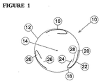
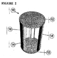
添付図面の図1および図2には、一対の端板ディスク12(図1では1つの端板ディスク12のみが示される)を有する風力タービン装置10が示される。端板ディスク12は中心軸14に取り付けられており、この端板ディスク12は中心軸14を中心として回転するよう設けられている。
1 and 2 of the accompanying drawings show a
風力タービン装置10は、複数の、この場合では3つの、非対称の空気を受ける薄片の(aerofoil)タービン翼16を更に有している。タービン翼16は、ディスク12の周縁部に設けられており、一対のディスク12間に配置されている。
The
各タービン翼16は、先頭エッジ18、後続エッジ20、外側の低圧力の揚力を生成する湾曲した表面22、および内側の比較的高い(大気の)圧力の表面24を有している。表面24は、後続エッジ20に対する距離の一部分の距離で、この場合約50%の距離で、先頭エッジ18から後方に延びている。このため、各々の表面24の後端部と対応する後続エッジ20との間に空間26が形成される。
Each
さらに、各タービン翼16は、このタービン翼16の表面22の内面と、対応する表面24の隣り合う面との間に形成される隙間28により、カップのようにへこんだ形となる。代わりに、タービン翼16は、後続エッジ20に隣り合う切断された部分が設けられたものであってもよい。
Further, each
添付図面の図3に、2つの翼タービン装置30が示されていること以外は図1に類似する図を示す。図3において、風の流れる方向を示す矢印31が複数示されている。タービンの回転方向は矢印32で示される。図示のように、矢印31により示される大気の風は、カップのようにへこんだ形となっている、下方への風に直面するタービン翼16の隙間28の中に押し込まれる。この動作により、タービン装置30の動作が開始される。
FIG. 3 of the accompanying drawings shows a view similar to FIG. 1 except that two
回転動作が一旦開始されると、(添付図面の図3に示される)下側のタービン翼16の表面22を越えて流れる風により、持ち上げ(浮揚、lift)効果が得られる。この持ち上げ効果により、タービン翼16の薄片の形状によって持ち上げ(浮揚)が行われる。
Once the rotational motion is initiated, the wind flowing over the
添付図面の図1乃至図3に示すような本発明の実施の形態に関して、タービン翼16は、上述の2つの端板ディスク12の間に都合良く保持されることに留意されたい。しかしながら、端板が設けられておらず、タービン翼16が中心軸14に向かって湾曲するようになっていてもよい。本発明の風力タービン装置10に用いられるタービン翼の数は2または3であることが好ましいが、必要に応じて、それ以上の数のタービン翼が用いられてもよい。
It should be noted that with respect to the embodiment of the present invention as shown in FIGS. 1-3 of the accompanying drawings, the
各タービン翼16におけるカップのようにへこんだ形の構成により、風力タービン装置10に抵抗効果および浮揚操作効果の二重の効果が与えられる。このような構成において、湾曲した外側の表面22の大部分が、端板ディスク12の外側の湾曲に続くようになっていることが好ましい。
The concave configuration like a cup in each
さらに、内側の高圧力の表面24は、先頭エッジ18から、先頭エッジ18と後続エッジ20との間の距離の10−90%の間の距離で、後方に延びるようにすることができる。しかしながら、この距離は、先頭エッジ18から後続エッジ20までの間の距離の約50−60%の間であることが好ましい。この距離は、より迅速な開始を行う性能と、周速比(風速に対する翼先端の周速度の比、Tip Speed Ratio(TSR))の性能とを両方満たすような好ましい値として発見されたものである。
Furthermore, the inner
このような構成により、完全な薄片から最小限の性能の変更を行うだけで、各タービン翼16の内部をスムーズに横切るよう流れるような風の通路のための十分な内部表面が得られる。
Such a configuration provides sufficient internal surfaces for wind passages that flow smoothly across the interior of each
しかしながら、後ろから見たときに、薄片のカップのようにへこんだ形状により、たとえ非常に弱い風であっても、風を捕捉することができ、このため、非常に弱い風の状況の場合でも風力タービン装置10の動作を開始させることができる。風力タービン装置10が一旦十分な回転速度を得ると、および/または風が十分な強さを得ると、浮揚タイプの装置として動作を開始することができ、風量タービン装置10は風の速度よりも早く回転することができる。周速比(TSR)が1を超え、また、概して1.5乃至3の範囲内で動作を行うことができることが発見された。
However, when viewed from the back, the concave shape like a cup of flakes makes it possible to capture the wind even in very weak winds, so even in very weak wind situations The operation of the
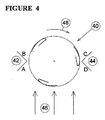
添付図面の図4に、図1に示すものと同様のタービン翼装置40が示されている。この実施の形態は、一対の対向する風偏向部材42、44を備えている。偏向部材42は、第1のプレートAおよび第2のプレートBを有している。偏向部材44は、第1のプレートDおよび第2のプレートCを有している。風の向きは矢印46で示され、タービン装置40は矢印48で示される方向に回転する。
FIG. 4 of the accompanying drawings shows a
添付図面の図5に、屋根54の尾根線52に取り付けられたタービン翼装置50を示す。風の向きは矢印56で示され、タービン装置50は矢印58で示される方向に回転する。タービン翼装置は支持フレーム59により取り付けられている。
FIG. 5 of the accompanying drawings shows a
風力タービン装置の周辺に偏向部材42、44を追加することにより、タービンの性能を向上させることができる。
By adding the deflecting
図4に示すような実施の形態に関して、プレートAおよびDは明らかにタービン装置40を通過する風を追加的に集中させるものであることがわかる。このため、これらのプレートにより、性能を向上させることができる。しかしながら、1つのプレートによる最も大きい個々の改善は、タービンへ風を押し込むことのないプレートBによるものであることがわかる。同様に、プレートCは、風を押し込むだけではなく、十分な改善を行うこととなる。このため、偏向部材42、44が、タービンを通過する風の流れのパターンを、より有利な性能の効果とするよう変えるという結果となる。好ましくは、偏向部材42、44の頂部エッジが、風力タービンから、風力タービンの直径の20%より小さい距離の箇所に設けられることが好ましく、このことにより、性能について十分な改善を行うことができる。
With respect to the embodiment as shown in FIG. 4, it can be seen that plates A and D clearly concentrate the wind passing through the
全ての4つのプレートA、B、CおよびDが用いられると、最大の効果が得られる。しかしながら、プレートA、B、CおよびDのうち一部のものを用いるだけでも、改善を行うことができる。 The maximum effect is obtained when all four plates A, B, C and D are used. However, improvement can be achieved by using only some of the plates A, B, C and D.
図5の実施の形態に関して、屋根54は、風偏向部材の一つの構成要素となる。このような屋根54により、図4に示す実施の形態の効果の一部が得られる。
With respect to the embodiment of FIG. 5, the
さらに、偏向部材42、44または尾根線52が、丸みのある頂部ではなく明りょうなV字形状の頂部を有するときに、最良の結果が得られる。
Further, best results are obtained when the deflecting
さらに、これらの技術は、屋根の頂部の尾根線を有さないような、商業ビルやオフィスのブロックにも適用することができる。この場合、風力タービン装置は、90°のビルの角のような、ビルの縁部に取り付けることができる。このような角は、本発明の装置の取り付けの機会を提供することがわかる。なぜならば、ビルの角は、風が集中する領域を提供し、自然の偏向プレートタイプの形状となっているからである。 Furthermore, these techniques can also be applied to commercial buildings and office blocks that do not have a ridgeline at the top of the roof. In this case, the wind turbine device can be attached to the edge of the building, such as a 90 ° building corner. It can be seen that such corners provide an opportunity for installation of the device of the present invention. This is because the corners of the building provide an area where the wind concentrates and have a natural deflection plate type shape.
さらに、屋根の頂部の尾根線およびビルの角は、本発明による風力タービン装置を取り付けるのに構造的に最も強い部分となっている。 Furthermore, the ridgeline at the top of the roof and the corners of the building are structurally the strongest parts for mounting the wind turbine apparatus according to the invention.
図6に、屋根の尾根線に取り付けられる風力タービン装置の3つの例が示されている。(a)において1つのモジュールが設けられており、(b)において2つのモジュールが設けられており、(c)において3つのモジュールが設けられている。 FIG. 6 shows three examples of wind turbine devices that are attached to the roof ridgeline. In (a), one module is provided, in (b), two modules are provided, and in (c), three modules are provided.
添付図面の図7に、従来の風力タービン装置70の概略端面図が示される。
A schematic end view of a conventional
図7において、中心回転軸72および複数の周辺の中実の薄片のタービン翼74を有する風力タービン装置70が示されている。タービン翼74は、図7に示す端面図で見たときに対称となっている。
In FIG. 7, a
タービン翼74は、先頭端部76および後続エッジ78を有している。タービンの回転方向は矢印77で示される。翼74は、軸72から延びる半径ライン75に対して90°の角度で配置されている。なお、この半径ライン75は、後続エッジ78から、タービン翼74が最も厚くなるような中間点まで延びるライン79と交差している。
The
図面からわかるように、各後続エッジ78は、ディスク12の境界を越えて外部に延びている。上記の90°の角度は、装置70の性能にとって不利益となることが発見されている。
As can be seen from the drawing, each trailing
図8に、本発明による風力タービン装置80が示されている。この風力タービン装置80において、中実の薄片のタービン翼74は、軸72から延びる半径ライン81に対して90°よりも小さい角度で配置されている。ここで、半径ライン81は、後続エッジ78から、タービン翼74が最も厚くなるような中間点まで延びるライン83と交差している。このような角度により、タービン装置80の性能について実質的な改善を導くことができることが発見されている。
FIG. 8 shows a
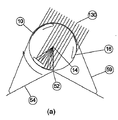
添付図面の図9に、図8に示すものと類似する、本発明のタービン翼タービン装置90が示されている。しかしながら、装置90は、図1に示すものに類似するような、一対のカップのようにへこんだタービン翼16を有している。この場合、各タービン翼16の後続エッジ20から、タービン翼16が最も厚くなるような中間点まで延びるラインは、約76°の角度で半径ライン92と交差する。
FIG. 9 of the accompanying drawings shows a turbine
上述のように、図8および図9に示すような、90°よりも小さい角度となるようなタービン翼の向きにより、改善された性能が得られることが理解される。この角度は、回転軸から、タービン翼が最も厚くなるような箇所の中心まで引かれるラインと、タービン翼が最も厚くなるよう箇所の中心から、後続エッジまで引かれるラインとの交差により決められるものである。90°よりも小さい角度のタービン翼の向きにより、揚抗比(lift to drag ratio)を向上させることができ、このことにより、従来のような90°の向きに配置されるタービン翼よりも改善された性能が得られる。 As mentioned above, it will be appreciated that improved performance can be obtained with the orientation of the turbine blade as shown in FIGS. 8 and 9 at an angle of less than 90 °. This angle is determined by the intersection of the line drawn from the rotation axis to the center of the location where the turbine blade is thickest and the line drawn from the center of the location where the turbine blade is thickest to the subsequent edge. It is. The orientation of the turbine blade at an angle smaller than 90 ° can improve the lift to drag ratio, which is an improvement over the conventional turbine blade arranged at 90 °. Performance is obtained.
添付図面の図10に、本発明による1つのモジュールの風力タービン装置100が示される。このような実施の形態において、2つの風力タービン部分10が一緒に配置されて1つの完全なモジュールを形成する。図示のように、これらのタービン部分10は、プレートディスク12と、軸14とともに設けられたタービン翼16とを有している。しかしながら、図示のように、一つの部分の2つのタービン翼16は、他の部分の2つのタービン翼16に対して90°回転したものとなっている。このような構成により、よりスムーズなトルク曲線が得られ、2つのタービン翼のみが設けられた1つの部分よりも、よりスムーズで良好なバランス性能が概して得られる。
FIG. 10 of the accompanying drawings shows a one-module
本発明の図11に、図1に示すものと同様の装置110が示される。しかしながら、この場合、装置110は、柔軟な後続エッジ114を有する薄片のタービン翼112を有している。
FIG. 11 of the present invention shows an
この実施の形態において、後続エッジ114は、回転速度が増加したときに後方に曲がる傾向があるということがわかる。このため、図示のように、各後続エッジ114は、その緩んだ静止位置から、回転速度が増加するにつれて外方に動くよう設けられている。このようにして、もし回転速度が過度に大きくなると、後続エッジ114は外方に曲がり、揚力が低くなるとともに抵抗効果が高くなり、装置110の回転速度の増加が抑制される。タービン翼112は、後続エッジに設けられるもの以外でも柔軟なものとすることができ、この場合でも、柔軟な後続エッジ114を使用することにより得られる結果と同様の結果が得られる。
In this embodiment, it can be seen that the trailing
このことは、ブレード角度を効果的に増加させ、それにより性能を減少させ、このことによって風速の増加に関する周速比を減少させる。このことは、高い風速回転率を減少させ、風が逃げる機会を減少させるとともに、ノイズ、振動およびタービンの損傷を減少させるようなシンプルな方法である。 This effectively increases the blade angle and thereby reduces performance, thereby reducing the peripheral speed ratio for increasing wind speed. This is a simple way to reduce high wind speed, reduce the chance of wind escape, and reduce noise, vibration and turbine damage.
本発明の風力タービン装置をモジュールスタイルのものとし、ビルのモジュール配置において複数のユニットが互いに接続されるようなものも考えられる。さらに、射出成形や押出のような低コストの量産技術により、個々のタービンを比較的容易に安価で製造するということも考えられる。さらに、ユニットがプラスチック材料から製造できるということも考えられる。さらに、上記の実施の形態では、水平な回転軸を有するユニットを使用しているが、鉛直な回転軸または水平方向と鉛直方向との間の方向に延びる回転軸を用いたユニットも考えられる。 It is also conceivable that the wind turbine apparatus of the present invention is of a modular style and a plurality of units are connected to each other in a building module arrangement. Furthermore, it may be possible to manufacture individual turbines relatively easily and inexpensively by low-cost mass production techniques such as injection molding and extrusion. It is also conceivable that the unit can be manufactured from a plastic material. Furthermore, in the above embodiment, a unit having a horizontal rotation axis is used, but a unit using a vertical rotation axis or a rotation axis extending in a direction between the horizontal direction and the vertical direction is also conceivable.
さらに、本発明の風力タービン装置は、とりわけ、発電に用いられることについても考えられる。このような場合、本発明のユニットは、通常時に使用できる電子コネクターを使用することができることや、モジュールシステムの複数のユニットが、太陽光パネルに用いられるのと同様の公知の方法で互いに接続できるということも考えられる。 Furthermore, the wind turbine apparatus of the present invention is also considered to be used for power generation, among others. In such a case, the unit of the present invention can use an electronic connector that can be used in a normal state, and a plurality of units of a module system can be connected to each other by a known method similar to that used for a solar panel. It can be considered.
本発明の装置は、風が集中するような外部の場所でビルに取り付けられるよう設計されているが、たいていの場合、これらの場所はたいてい日当たりが良いようになっている。このことにより、装置が水を熱するような性能も有している場合、この装置はコストを十分に節約することができる。 The devices of the present invention are designed to be attached to the building at external locations where the wind is concentrated, but in most cases these locations are usually sunny. This allows the device to save significant costs if it also has the ability to heat water.
現状では、風力タービンおよび太陽光給湯システムは、完全に別のものとなっている。両方のものは個々に設けられ、それぞれの別個の取付フレームが必要となる。これらの取付フレームは、従来の太陽光給湯システムの導入コストと組み合わせて、一般的に全体のシステムのコストの3分の1を占めるようになる。従来の公知の技術の形態において、風力タービンと太陽光による給湯との間で、相乗効果は現在のところ存在しない。 At present, wind turbines and solar water heating systems are completely different. Both are provided individually and require a separate mounting frame for each. These mounting frames generally occupy one-third of the total system cost in combination with the cost of introducing a conventional solar water heating system. There is currently no synergistic effect between wind turbines and solar hot water in the form of prior known technology.
本発明の装置では、タービンの発電性能に影響を与えることなく、太陽光を利用することにより、水を加熱する(給湯)性能を組み込むことができる。このことは、タービン自体の基本のコストに対して、わずかなコストの追加で、給湯を行うことができるという利点がある。消費者が従来の太陽光給湯システムにおいて従来のような大きなコストを支払わなければならない代わりに、本発明の装置の購入にそれを組み込むことによって、小さなコストで給湯を行うことができる。この方法により、消費者は、発電を行うことができることに加えて、太陽光給湯システムのコストを節減することができる。 In the apparatus of the present invention, the ability to heat water (hot water supply) can be incorporated by utilizing sunlight without affecting the power generation performance of the turbine. This has the advantage that hot water can be supplied with a slight addition to the basic cost of the turbine itself. Instead of having to pay large costs as in the past in conventional solar water heating systems, consumers can supply hot water at a low cost by incorporating it into the purchase of the device of the present invention. By this method, the consumer can reduce the cost of the solar hot water supply system in addition to being able to generate power.
本発明の装置に太陽光給湯システムを組み込む方法として、様々な方法がある。 There are various methods for incorporating a solar water heating system into the apparatus of the present invention.
図12(a)に示すような一の例において、チューブの形態の軸14を通るよう水を流し、タービン翼の内部に、放物線状(パラボラアンテナ状)のマイクロストリップの反射部を組み込んでいる。太陽光線130は、ブレード翼の内部で反射し、軸のチューブ上に集中する。このことにより水を加熱する。太陽光の一部分は回転するタービン翼によりブロックされるが、この方法は、幅広い太陽の角度に適合するという利点がある。
In one example as shown in FIG. 12A, water is allowed to flow through a
他の例として、取付フレームのベース59を通るよう水を流し、図12(b)の参照符号122に示すような従来の太陽光加熱手段を介して加熱を行うものがある。
As another example, water is allowed to flow through the
他の例として、取付フレームの頂部を通るよう水を流し、図12(b)の参照符号124に示すような従来の太陽光加熱手段を介して加熱を行うものがある。 As another example, water is allowed to flow through the top of the mounting frame, and heating is performed through conventional solar heating means as indicated by reference numeral 124 in FIG.
図13(a)(b)に、切断された輪郭を有するタービン翼131、132の例を示す。これらのタービン翼は、図1および2に示すようなタービン翼16の代わりに使用することができる。図示のように、これらのタービン翼の実施の形態は、間隙28を有しておらず、代わりに先頭エッジ18から後続エッジ20に向かって部分的に延びる表面24を有している。
FIGS. 13A and 13B show examples of
このことにより、各々の場合において、隙間28と同様の方法で、動作開始時に風を捉えるよう構成された、後方に面する表面134が設けられることとなる。
This provides in each case a rear-facing
本発明の範囲内において、当業者にとって改良および変更を行うことができることは明らかである。 It will be apparent to those skilled in the art that improvements and modifications can be made within the scope of the invention.
Claims (14)
Applications Claiming Priority (3)
| Application Number | Priority Date | Filing Date | Title |
|---|---|---|---|
| AU2006906751A AU2006906751A0 (en) | 2006-12-04 | Modular wind turbine system | |
| AU2007904481A AU2007904481A0 (en) | 2007-08-21 | Modular wind turbine system | |
| PCT/AU2007/001865 WO2008067593A1 (en) | 2006-12-04 | 2007-12-04 | A wind turbine apparatus |
Publications (2)
| Publication Number | Publication Date |
|---|---|
| JP2010511831A true JP2010511831A (en) | 2010-04-15 |
| JP2010511831A5 JP2010511831A5 (en) | 2011-01-27 |
Family
ID=39491561
Family Applications (1)
| Application Number | Title | Priority Date | Filing Date |
|---|---|---|---|
| JP2009539570A Pending JP2010511831A (en) | 2006-12-04 | 2007-12-04 | Wind turbine equipment |
Country Status (9)
| Country | Link |
|---|---|
| US (1) | US9303622B2 (en) |
| EP (1) | EP2102493B1 (en) |
| JP (1) | JP2010511831A (en) |
| CN (1) | CN101583792B (en) |
| AU (1) | AU2007329173B2 (en) |
| CA (1) | CA2671858C (en) |
| HK (1) | HK1137206A1 (en) |
| NZ (1) | NZ578143A (en) |
| WO (1) | WO2008067593A1 (en) |
Cited By (3)
| Publication number | Priority date | Publication date | Assignee | Title |
|---|---|---|---|---|
| JP2011038468A (en) * | 2009-08-11 | 2011-02-24 | Global Energy Co Ltd | Power generation vehicle |
| JP2014501357A (en) * | 2010-12-31 | 2014-01-20 | ワルター・ダカス | Wind turbine with vertical axis |
| JP6302591B1 (en) * | 2017-06-08 | 2018-03-28 | 豊 根本 | Wind generator for high-rise roof |
Families Citing this family (15)
| Publication number | Priority date | Publication date | Assignee | Title |
|---|---|---|---|---|
| CN101583792B (en) | 2006-12-04 | 2013-02-13 | 设计许可国际集团有限公司 | A wind turbine apparatus |
| CA2723468C (en) | 2008-05-07 | 2016-11-29 | Design Licensing International Pty Ltd | Wind turbine having wind barriers |
| GB0912695D0 (en) | 2009-07-22 | 2009-08-26 | Power Collective The Ltd | A generator |
| KR101068443B1 (en) * | 2009-12-24 | 2011-09-28 | 황지선 | Wind power rotors |
| FR2957387B1 (en) * | 2010-03-09 | 2017-05-12 | Erick Gros-Dubois | HIGH PERFORMANCE WIND EOLIVE |
| WO2012028893A2 (en) * | 2010-08-31 | 2012-03-08 | Matrahazi Janos | Wind turbine |
| US20110232630A1 (en) * | 2011-06-03 | 2011-09-29 | Jason Tsao | Solar collector/wind deflector conversion of a solar and wind converter |
| US9022721B2 (en) | 2011-10-10 | 2015-05-05 | Wind Power Systems, LLC | Vertical axis wind turbine |
| AT512326B1 (en) * | 2011-12-29 | 2013-09-15 | Wind Gmbh T | TURBOMACHINE |
| CN102562442B (en) * | 2012-02-07 | 2015-09-16 | 秦皇岛风日和科技有限公司 | Vane of vertical shaft wind-driven generator |
| BE1020677A3 (en) * | 2012-05-08 | 2014-03-04 | Devisch Geert | WIND TURBINE AND BUILDING INCLUDING SUCH WIND TURBINE. |
| WO2015014370A1 (en) * | 2013-08-02 | 2015-02-05 | Vestas Wind Systems A/S | A blade for a wind turbine and a method for manufacturing a blade for a wind turbine |
| USD766808S1 (en) * | 2014-08-20 | 2016-09-20 | Don Allen Harwood | Wing with slipstream turbine |
| US10487799B2 (en) * | 2015-12-18 | 2019-11-26 | Dan Pendergrass | Pressure and vacuum assisted vertical axis wind turbines |
| CN110735763A (en) * | 2019-10-31 | 2020-01-31 | 祁家琦 | vertical axis wind-driven generator |
Citations (8)
| Publication number | Priority date | Publication date | Assignee | Title |
|---|---|---|---|---|
| JPS5390543A (en) * | 1977-01-18 | 1978-08-09 | Jiyuntarou Yamada | Tower type exchanging apparatus of wind and sun shine energy |
| JPS59501870A (en) * | 1982-10-06 | 1984-11-08 | ヨンソン・ポンプコンサルト | Rotary motion type turbo device |
| JPH11336340A (en) * | 1998-05-25 | 1999-12-07 | Kumagai Gumi Co Ltd | Feeding device |
| JP2001193631A (en) * | 2000-01-11 | 2001-07-17 | Penta Ocean Constr Co Ltd | Wind-force power generating device |
| JP2003206849A (en) * | 2001-11-08 | 2003-07-25 | Tokai Univ | Straight wing type wind and water turbine |
| JP2004108330A (en) * | 2002-09-20 | 2004-04-08 | Tsuneo Noguchi | Windmill for wind power generation |
| JP2005036649A (en) * | 2003-04-23 | 2005-02-10 | Shinko Electric Co Ltd | Vertical shaft wind power generator |
| JP2005220893A (en) * | 2004-02-03 | 2005-08-18 | Dmw Japan:Kk | Wind velocity increasing device with wind direction rudder attached to omnidirectional vertical wind mill |
Family Cites Families (63)
| Publication number | Priority date | Publication date | Assignee | Title |
|---|---|---|---|---|
| US705922A (en) * | 1901-11-13 | 1902-07-29 | Albert Gran | Wind-motor. |
| US1574171A (en) * | 1924-04-02 | 1926-02-23 | James T Ryan | Windmill |
| FR604390A (en) * | 1925-10-09 | 1926-05-03 | Leblanc Vickers Maurice Sa | Turbine with axis of rotation transverse to the direction of the current |
| GB561435A (en) | 1942-12-23 | 1944-05-19 | Charles Owen Griffith | Turbines |
| US3033441A (en) * | 1956-05-08 | 1962-05-08 | Benninger Ag Maschf | Turbomachine |
| US3070287A (en) * | 1959-07-16 | 1962-12-25 | Eck Bruno | Drum rotor for radial blower |
| FR2395409A1 (en) * | 1977-06-20 | 1979-01-19 | Lagarde Jean De | FLEXIBLE BLADE AND AEROGENERATOR WITH VERTICAL AXIS INCLUDING SUCH BLADES |
| US4162410A (en) * | 1977-11-30 | 1979-07-24 | Amick James L | Vertical-axis windmill |
| US4247251A (en) * | 1978-05-17 | 1981-01-27 | Wuenscher Hans F | Cycloidal fluid flow engine |
| NL7809790A (en) * | 1978-09-27 | 1980-03-31 | Mattheus Willem Verplanke | DEVICE FOR GENERATING ENERGY FROM A FLOWING MEDIUM. |
| US4245958A (en) * | 1978-11-22 | 1981-01-20 | Ewers Marion H | Vertical axis wind turbine |
| JPS55142978A (en) | 1979-04-23 | 1980-11-07 | Ogawa Kenbi:Kk | Vertical shaft wind wheel |
| GB2049066A (en) | 1979-05-09 | 1980-12-17 | Santos Afonso L D | Apparatus for generating energy |
| US4321476A (en) * | 1980-06-24 | 1982-03-23 | Buels Jesse H | Bi-directional wind power generator |
| GB2082260B (en) * | 1980-08-20 | 1984-01-25 | Nianbilla Co Ltd | Vertical axis windmill |
| SE433648B (en) * | 1981-05-15 | 1984-06-04 | Saab Scania Ab | SPEED LIMITING DEVICE ON A VERTICAL SHADE WIND TURBINE |
| US4379972A (en) * | 1981-05-26 | 1983-04-12 | Daniel T. Sosa | Turbine ventilator |
| US4430044A (en) * | 1981-11-23 | 1984-02-07 | Liljegren L Kenyon | Vertical axis wind turbine |
| US4486143A (en) * | 1982-09-01 | 1984-12-04 | Mcvey Paul W | Turbine-type wind machine |
| GB8626347D0 (en) * | 1986-11-04 | 1986-12-03 | Bicc Plc | Wind energy convertor |
| US5076759A (en) | 1986-10-29 | 1991-12-31 | Schoenell Juergen | Windmill |
| SU1733680A1 (en) * | 1990-01-03 | 1992-05-15 | Сумский филиал Харьковского политехнического института им.В.И.Ленина | Wind-wheel blade |
| SU1733681A1 (en) | 1990-04-27 | 1992-05-15 | Научно-Производственное Объединение По Исследованию И Проектированию Энергетического Оборудования Им.И.И.Ползунова | Wind wheel |
| GR910200234U (en) * | 1990-05-31 | 1992-07-30 | Mihail Valsamidis | Turbine wind machine with a vertical axis |
| US5527151A (en) * | 1992-03-04 | 1996-06-18 | Northern Power Systems, Inc. | Advanced wind turbine with lift-destroying aileron for shutdown |
| RU2044157C1 (en) * | 1992-07-31 | 1995-09-20 | Лев Анатольевич Степанов | Aerohydrodynamic windmill |
| RU2096259C1 (en) * | 1993-11-15 | 1997-11-20 | Владимир Викторович Мозжилкин | Rotary vertical axial wind motor |
| US5642984A (en) * | 1994-01-11 | 1997-07-01 | Northeastern University | Helical turbine assembly operable under multidirectional fluid flow for power and propulsion systems |
| US5451138A (en) * | 1994-01-11 | 1995-09-19 | Northeastern University | Unidirecional reaction turbine operable under reversible fluid from flow |
| US5640984A (en) * | 1995-09-12 | 1997-06-24 | Dubunsky; Emanuel | Special fold-up umbrella having rib and frame design for easier opening and closing of umbrella, and two canopies designed to stabilize the ribs and vent the air |
| FR2752599B1 (en) * | 1996-08-23 | 2002-11-29 | Gual Georges Jean | STATO-WIND MODULE WITH FLAT AND PERIPTER CONFORMATION |
| JPH11107907A (en) * | 1997-10-04 | 1999-04-20 | Yoshiro Nakamatsu | Convection energy apparatus |
| US6097104A (en) * | 1999-01-19 | 2000-08-01 | Russell; Thomas H. | Hybrid energy recovery system |
| IL126678A (en) * | 1998-10-20 | 2003-01-12 | Bruce Brill | Modular wind energy device |
| US6884020B2 (en) * | 1999-01-06 | 2005-04-26 | Water Power Industries As | Turbine driven with a fluid medium |
| JP2002021705A (en) * | 2000-07-05 | 2002-01-23 | Koji Iizuka | Windmill for installation on roof |
| US6784566B2 (en) * | 2001-01-25 | 2004-08-31 | Robert Nason Thomas | Coupled vortex vertical axis wind turbine |
| NL1019855C2 (en) * | 2001-06-13 | 2002-12-16 | Ngup Holding B V | Wind turbine rotor, has specific rotor blade length to rotor diameter ratio |
| US6877948B2 (en) * | 2001-07-10 | 2005-04-12 | Alan B. Cutcher | Wind turbine generator |
| US6538340B2 (en) | 2001-08-06 | 2003-03-25 | Headwinds Corporation | Wind turbine system |
| JP2003065206A (en) * | 2001-08-24 | 2003-03-05 | Daiwa House Ind Co Ltd | Windmill installed building structure |
| US6638005B2 (en) * | 2002-01-17 | 2003-10-28 | John W. Holter | Coaxial wind turbine apparatus having a closeable air inlet opening |
| US6870280B2 (en) * | 2002-05-08 | 2005-03-22 | Elcho R. Pechler | Vertical-axis wind turbine |
| JP2004019537A (en) * | 2002-06-17 | 2004-01-22 | Ko Yamaguchi | Clean energy generator |
| US6740989B2 (en) * | 2002-08-21 | 2004-05-25 | Pacifex Management Inc. | Vertical axis wind turbine |
| JP2004176551A (en) * | 2002-11-25 | 2004-06-24 | Satsuki Seisakusho:Kk | Darrieus windmill |
| US6814070B2 (en) * | 2003-01-06 | 2004-11-09 | Davis Energy Group, Inc. | Molded polymer solar water heater |
| US6966747B2 (en) * | 2003-04-30 | 2005-11-22 | Taylor Ronald J | Wind turbine having airfoils for blocking and directing wind and rotors with or without a central gap |
| DE10328249A1 (en) * | 2003-06-24 | 2005-02-03 | Roland Reinhard | Blade profile for rotor blade of wind-powered energy plant provided by combination of resistance rotor blade and aerodynamic rotor blade |
| GB2404700A (en) * | 2003-08-01 | 2005-02-09 | Robin Matthew Hilder | Roof mounted wind turbine |
| RU2249125C1 (en) * | 2003-09-24 | 2005-03-27 | Царев Виктор Владимирович | Self-contained power and heat supply system of rooms in dwelling houses and industrial areas |
| US7008171B1 (en) * | 2004-03-17 | 2006-03-07 | Circle Wind Corp. | Modified Savonius rotor |
| KR100571123B1 (en) * | 2004-03-19 | 2006-04-14 | 주장식 | Wind generator capable of hot water heating using solar heat |
| US7109599B2 (en) * | 2004-05-05 | 2006-09-19 | Watkins Philip G | Omni-directional wind turbine electric generation system |
| US20070224029A1 (en) * | 2004-05-27 | 2007-09-27 | Tadashi Yokoi | Blades for a Vertical Axis Wind Turbine, and the Vertical Axis Wind Turbine |
| ITCE20050006A1 (en) * | 2005-03-11 | 2006-09-12 | Mast S R L B | WIND TURBINE WITH WING-MOUNT ROTOR AND CONVEYOR |
| FR2886353A1 (en) | 2005-05-27 | 2006-12-01 | Michel Georges Ponge | Wind energy transforming device for e.g. firm, has stator with air inlets delimited by walls channeling air to rotor having vertical vanes, where inlets and vanes are fixed at top and bottom to plates and reinforced by horizontal tympanums |
| WO2007027113A1 (en) | 2005-09-02 | 2007-03-08 | Ballena Abraham E | Vertical axis wind turbine |
| GB2431696B (en) * | 2005-10-28 | 2007-10-03 | Adrian Raphael Montford | Roof Turbine |
| GB0612677D0 (en) * | 2006-06-27 | 2006-08-09 | Taylor Derek A | Energy conversion device for wind & other fluids |
| CN101583792B (en) | 2006-12-04 | 2013-02-13 | 设计许可国际集团有限公司 | A wind turbine apparatus |
| CA2723468C (en) | 2008-05-07 | 2016-11-29 | Design Licensing International Pty Ltd | Wind turbine having wind barriers |
| WO2010124692A1 (en) * | 2009-04-28 | 2010-11-04 | Soeren Bang-Moeller | Combined wing and turbine device for improved utilization of fluid flow energy |
-
2007
- 2007-12-04 CN CN2007800498941A patent/CN101583792B/en not_active Expired - Fee Related
- 2007-12-04 NZ NZ578143A patent/NZ578143A/en not_active IP Right Cessation
- 2007-12-04 EP EP07815663.5A patent/EP2102493B1/en not_active Not-in-force
- 2007-12-04 JP JP2009539570A patent/JP2010511831A/en active Pending
- 2007-12-04 CA CA2671858A patent/CA2671858C/en not_active Expired - Fee Related
- 2007-12-04 WO PCT/AU2007/001865 patent/WO2008067593A1/en active Application Filing
- 2007-12-04 AU AU2007329173A patent/AU2007329173B2/en not_active Ceased
-
2009
- 2009-06-04 US US12/478,597 patent/US9303622B2/en not_active Expired - Fee Related
-
2010
- 2010-04-27 HK HK10104109.8A patent/HK1137206A1/en not_active IP Right Cessation
Patent Citations (8)
| Publication number | Priority date | Publication date | Assignee | Title |
|---|---|---|---|---|
| JPS5390543A (en) * | 1977-01-18 | 1978-08-09 | Jiyuntarou Yamada | Tower type exchanging apparatus of wind and sun shine energy |
| JPS59501870A (en) * | 1982-10-06 | 1984-11-08 | ヨンソン・ポンプコンサルト | Rotary motion type turbo device |
| JPH11336340A (en) * | 1998-05-25 | 1999-12-07 | Kumagai Gumi Co Ltd | Feeding device |
| JP2001193631A (en) * | 2000-01-11 | 2001-07-17 | Penta Ocean Constr Co Ltd | Wind-force power generating device |
| JP2003206849A (en) * | 2001-11-08 | 2003-07-25 | Tokai Univ | Straight wing type wind and water turbine |
| JP2004108330A (en) * | 2002-09-20 | 2004-04-08 | Tsuneo Noguchi | Windmill for wind power generation |
| JP2005036649A (en) * | 2003-04-23 | 2005-02-10 | Shinko Electric Co Ltd | Vertical shaft wind power generator |
| JP2005220893A (en) * | 2004-02-03 | 2005-08-18 | Dmw Japan:Kk | Wind velocity increasing device with wind direction rudder attached to omnidirectional vertical wind mill |
Cited By (4)
| Publication number | Priority date | Publication date | Assignee | Title |
|---|---|---|---|---|
| JP2011038468A (en) * | 2009-08-11 | 2011-02-24 | Global Energy Co Ltd | Power generation vehicle |
| JP2014501357A (en) * | 2010-12-31 | 2014-01-20 | ワルター・ダカス | Wind turbine with vertical axis |
| JP6302591B1 (en) * | 2017-06-08 | 2018-03-28 | 豊 根本 | Wind generator for high-rise roof |
| JP2018204584A (en) * | 2017-06-08 | 2018-12-27 | 豊 根本 | Wind power generator for high-rise roof |
Also Published As
| Publication number | Publication date |
|---|---|
| CA2671858C (en) | 2015-09-29 |
| AU2007329173B2 (en) | 2013-12-19 |
| CN101583792A (en) | 2009-11-18 |
| CN101583792B (en) | 2013-02-13 |
| AU2007329173A1 (en) | 2008-06-12 |
| HK1137206A1 (en) | 2010-07-23 |
| EP2102493B1 (en) | 2017-05-03 |
| WO2008067593A1 (en) | 2008-06-12 |
| US20090304512A1 (en) | 2009-12-10 |
| NZ578143A (en) | 2013-01-25 |
| CA2671858A1 (en) | 2008-06-12 |
| EP2102493A4 (en) | 2010-10-20 |
| EP2102493A1 (en) | 2009-09-23 |
| US9303622B2 (en) | 2016-04-05 |
Similar Documents
| Publication | Publication Date | Title |
|---|---|---|
| JP2010511831A (en) | Wind turbine equipment | |
| US10612515B2 (en) | Vertical axis wind turbine | |
| US9284944B2 (en) | Vertical shaft type darius windmill | |
| US9041239B2 (en) | Vertical axis wind turbine with cambered airfoil blades | |
| US20110020123A1 (en) | Wind Turbine with Adjustable Airfoils | |
| JP2013217372A (en) | Flexible flap arrangement for wind turbine rotor blade | |
| US20080166242A1 (en) | Wind Turbine Rotor Projection | |
| WO2010098656A2 (en) | Wind, solar and rain harvester | |
| US11236724B2 (en) | Vertical axis wind turbine | |
| WO2008002542A2 (en) | Wind turbine having variable pitch airfoils | |
| WO2010005289A2 (en) | Wind turbine with di ffuser | |
| US20130017084A1 (en) | High efficiency verical axis wind turbine | |
| US20180135599A1 (en) | Wind turbine | |
| US8564147B1 (en) | System for solar and wind energy collection with advanced blade design | |
| US8419371B2 (en) | Wind turbine blades with twisted and tapered tips | |
| US20110187114A1 (en) | Wind driven turbine | |
| WO2017144837A1 (en) | Wind turbine system, method and application | |
| WO2021017033A1 (en) | Blade swinging type flow guiding vertical axis wind turbine | |
| CN105041564A (en) | Wind wheel of vertical-axis wind turbine | |
| CN102011685A (en) | A resistance wind turbine or water turbine with deflective flow cover rotating along with flow direction | |
| US20130149161A1 (en) | Conical wind turbine | |
| GB2603641A (en) | Portable wind turbine | |
| KR101263935B1 (en) | Turbine blade and wind power generator with the same | |
| WO2011056835A1 (en) | Horizontal axis radial wind turbine | |
| WO2020194203A1 (en) | Horizontal-axis turbine for a wind generator, and wind generator comprising said turbine |
Legal Events
| Date | Code | Title | Description |
|---|---|---|---|
| A521 | Written amendment |
Free format text: JAPANESE INTERMEDIATE CODE: A523 Effective date: 20101130 |
|
| A621 | Written request for application examination |
Free format text: JAPANESE INTERMEDIATE CODE: A621 Effective date: 20101130 |
|
| A977 | Report on retrieval |
Free format text: JAPANESE INTERMEDIATE CODE: A971007 Effective date: 20130121 |
|
| A131 | Notification of reasons for refusal |
Free format text: JAPANESE INTERMEDIATE CODE: A131 Effective date: 20130125 |
|
| A521 | Written amendment |
Free format text: JAPANESE INTERMEDIATE CODE: A523 Effective date: 20130423 |
|
| A131 | Notification of reasons for refusal |
Free format text: JAPANESE INTERMEDIATE CODE: A131 Effective date: 20131022 |
|
| A521 | Written amendment |
Free format text: JAPANESE INTERMEDIATE CODE: A523 Effective date: 20140122 |
|
| A02 | Decision of refusal |
Free format text: JAPANESE INTERMEDIATE CODE: A02 Effective date: 20140624 |