JP2010509582A - Object position and localization detection system - Google Patents
Object position and localization detection system Download PDFInfo
- Publication number
- JP2010509582A JP2010509582A JP2009535809A JP2009535809A JP2010509582A JP 2010509582 A JP2010509582 A JP 2010509582A JP 2009535809 A JP2009535809 A JP 2009535809A JP 2009535809 A JP2009535809 A JP 2009535809A JP 2010509582 A JP2010509582 A JP 2010509582A
- Authority
- JP
- Japan
- Prior art keywords
- pattern
- localization
- object position
- light source
- marker
- Prior art date
- Legal status (The legal status is an assumption and is not a legal conclusion. Google has not performed a legal analysis and makes no representation as to the accuracy of the status listed.)
- Pending
Links
Images


Classifications
-
- G—PHYSICS
- G01—MEASURING; TESTING
- G01B—MEASURING LENGTH, THICKNESS OR SIMILAR LINEAR DIMENSIONS; MEASURING ANGLES; MEASURING AREAS; MEASURING IRREGULARITIES OF SURFACES OR CONTOURS
- G01B11/00—Measuring arrangements characterised by the use of optical techniques
- G01B11/002—Measuring arrangements characterised by the use of optical techniques for measuring two or more coordinates
-
- G—PHYSICS
- G06—COMPUTING; CALCULATING OR COUNTING
- G06F—ELECTRIC DIGITAL DATA PROCESSING
- G06F3/00—Input arrangements for transferring data to be processed into a form capable of being handled by the computer; Output arrangements for transferring data from processing unit to output unit, e.g. interface arrangements
- G06F3/01—Input arrangements or combined input and output arrangements for interaction between user and computer
- G06F3/017—Gesture based interaction, e.g. based on a set of recognized hand gestures
-
- G—PHYSICS
- G06—COMPUTING; CALCULATING OR COUNTING
- G06F—ELECTRIC DIGITAL DATA PROCESSING
- G06F3/00—Input arrangements for transferring data to be processed into a form capable of being handled by the computer; Output arrangements for transferring data from processing unit to output unit, e.g. interface arrangements
- G06F3/01—Input arrangements or combined input and output arrangements for interaction between user and computer
- G06F3/03—Arrangements for converting the position or the displacement of a member into a coded form
- G06F3/0304—Detection arrangements using opto-electronic means
- G06F3/0325—Detection arrangements using opto-electronic means using a plurality of light emitters or reflectors or a plurality of detectors forming a reference frame from which to derive the orientation of the object, e.g. by triangulation or on the basis of reference deformation in the picked up image
-
- G—PHYSICS
- G06—COMPUTING; CALCULATING OR COUNTING
- G06F—ELECTRIC DIGITAL DATA PROCESSING
- G06F3/00—Input arrangements for transferring data to be processed into a form capable of being handled by the computer; Output arrangements for transferring data from processing unit to output unit, e.g. interface arrangements
- G06F3/01—Input arrangements or combined input and output arrangements for interaction between user and computer
- G06F3/03—Arrangements for converting the position or the displacement of a member into a coded form
- G06F3/033—Pointing devices displaced or positioned by the user, e.g. mice, trackballs, pens or joysticks; Accessories therefor
- G06F3/0346—Pointing devices displaced or positioned by the user, e.g. mice, trackballs, pens or joysticks; Accessories therefor with detection of the device orientation or free movement in a 3D space, e.g. 3D mice, 6-DOF [six degrees of freedom] pointers using gyroscopes, accelerometers or tilt-sensors
-
- G—PHYSICS
- G06—COMPUTING; CALCULATING OR COUNTING
- G06F—ELECTRIC DIGITAL DATA PROCESSING
- G06F3/00—Input arrangements for transferring data to be processed into a form capable of being handled by the computer; Output arrangements for transferring data from processing unit to output unit, e.g. interface arrangements
- G06F3/01—Input arrangements or combined input and output arrangements for interaction between user and computer
- G06F3/03—Arrangements for converting the position or the displacement of a member into a coded form
- G06F3/033—Pointing devices displaced or positioned by the user, e.g. mice, trackballs, pens or joysticks; Accessories therefor
- G06F3/0354—Pointing devices displaced or positioned by the user, e.g. mice, trackballs, pens or joysticks; Accessories therefor with detection of 2D relative movements between the device, or an operating part thereof, and a plane or surface, e.g. 2D mice, trackballs, pens or pucks
- G06F3/03545—Pens or stylus
-
- G—PHYSICS
- G06—COMPUTING; CALCULATING OR COUNTING
- G06F—ELECTRIC DIGITAL DATA PROCESSING
- G06F3/00—Input arrangements for transferring data to be processed into a form capable of being handled by the computer; Output arrangements for transferring data from processing unit to output unit, e.g. interface arrangements
- G06F3/01—Input arrangements or combined input and output arrangements for interaction between user and computer
- G06F3/03—Arrangements for converting the position or the displacement of a member into a coded form
- G06F3/041—Digitisers, e.g. for touch screens or touch pads, characterised by the transducing means
- G06F3/042—Digitisers, e.g. for touch screens or touch pads, characterised by the transducing means by opto-electronic means
- G06F3/0425—Digitisers, e.g. for touch screens or touch pads, characterised by the transducing means by opto-electronic means using a single imaging device like a video camera for tracking the absolute position of a single or a plurality of objects with respect to an imaged reference surface, e.g. video camera imaging a display or a projection screen, a table or a wall surface, on which a computer generated image is displayed or projected
-
- G—PHYSICS
- G06—COMPUTING; CALCULATING OR COUNTING
- G06V—IMAGE OR VIDEO RECOGNITION OR UNDERSTANDING
- G06V10/00—Arrangements for image or video recognition or understanding
- G06V10/10—Image acquisition
- G06V10/12—Details of acquisition arrangements; Constructional details thereof
- G06V10/14—Optical characteristics of the device performing the acquisition or on the illumination arrangements
- G06V10/145—Illumination specially adapted for pattern recognition, e.g. using gratings
-
- G—PHYSICS
- G06—COMPUTING; CALCULATING OR COUNTING
- G06V—IMAGE OR VIDEO RECOGNITION OR UNDERSTANDING
- G06V10/00—Arrangements for image or video recognition or understanding
- G06V10/20—Image preprocessing
- G06V10/24—Aligning, centring, orientation detection or correction of the image
- G06V10/245—Aligning, centring, orientation detection or correction of the image by locating a pattern; Special marks for positioning
-
- G—PHYSICS
- G06—COMPUTING; CALCULATING OR COUNTING
- G06F—ELECTRIC DIGITAL DATA PROCESSING
- G06F3/00—Input arrangements for transferring data to be processed into a form capable of being handled by the computer; Output arrangements for transferring data from processing unit to output unit, e.g. interface arrangements
- G06F3/01—Input arrangements or combined input and output arrangements for interaction between user and computer
- G06F3/03—Arrangements for converting the position or the displacement of a member into a coded form
- G06F3/041—Digitisers, e.g. for touch screens or touch pads, characterised by the transducing means
- G06F3/044—Digitisers, e.g. for touch screens or touch pads, characterised by the transducing means by capacitive means
Abstract
【課題】高価なハードウェアを必要とせずに機能する物体の位置及び定位検出システムを提供する。
【解決手段】物体の位置及び定位検出システム、特に視認された3次元の動きを記述できるシステムが提供される。1例では、同心リングをもつ球体のパターンを形成するマーカーが1または複数のデジタルカメラを用いて撮像され、その像がパターンを形成するマーカーが取り付けられる物体の位置及び定位を決定するために処理される。本システムで使用される光学追跡方法により運動を6自由度で決定することができる。適切なディスプレイに接続して、投影器、会話型のホワイトボードまたは類似の応用が実現可能である。
【選択図】図5An object position and localization detection system that functions without requiring expensive hardware is provided.
An object position and localization detection system, in particular a system capable of describing a visually recognized three-dimensional movement, is provided. In one example, a marker that forms a pattern of spheres with concentric rings is imaged using one or more digital cameras, and the image is processed to determine the position and orientation of the object to which the marker forming the pattern is attached. Is done. Motion can be determined with 6 degrees of freedom by the optical tracking method used in the system. Connected to a suitable display, a projector, interactive whiteboard or similar application can be realized.
[Selection] Figure 5
Description
本発明は物体の位置及び定位(orientation)検出システムに関し、特に、視認される3次元の動きを決定できる位置及び定位検出システムに関する。 The present invention relates to an object position and orientation detection system, and more particularly, to a position and orientation detection system capable of determining a three-dimensional motion to be visually recognized.
ボードを横切って拡がった接触感応表面を用いて投影像に書き込みできるインターフェイス装置は公知である。しかしながら、そのような装置による相互作用性(対話式利用)のレベルは標準のデスクトップマウスで達成されるよりも低いレベルに限られる。そのようなシステムはまた高価であり、かつそれらを効果的にするために付加的なハードウェアの購入が必要である。 Interface devices that can write to a projected image using a touch-sensitive surface that extends across the board are known. However, the level of interactivity (interactive use) with such devices is limited to a level lower than that achieved with a standard desktop mouse. Such systems are also expensive and require the purchase of additional hardware to make them effective.
したがって、本発明の具体的な目的は、高価なハードウェアの付加を必要とせずに機能し得る物体の位置及び定位検出システムを提供することにある。 Accordingly, a specific object of the present invention is to provide an object position and localization detection system that can function without the need for expensive hardware.
本発明の第1の形態によれば、少なくとも物体の一部がその物体上に配置された検出可能なパターンを備えたパターンを形成するマーカーを有する物体と、
物体の1またはそれ以上の像を生成する結像手段と、
パターンを形成するマーカーの位置及び定位から空間内の物体の位置及び定位を計算する像処理手段とを有する物体の位置及び定位検出システムが提供される。
According to a first aspect of the present invention, an object having a marker forming a pattern with a detectable pattern at least part of the object disposed on the object;
Imaging means for generating one or more images of the object;
An object position and localization detection system is provided having image processing means for calculating the position and localization of an object in space from the position and localization of a marker forming a pattern.
好ましくは、物体の位置及び定位はリアルタイムで計算される。
このシステムは、3次元空間のまわりに動きかつ転回したとき、物体の軌道及び定位(6自由度で)をモニターし得るので、効率的な物体の位置及び定位検出装置となる。
好ましくは、結像手段によって視認されるパターンは結像手段に関連するパターンを形成するマーカーの定位に依存して変化する。
オプションとしては(optionally)、結像手段によって視認されるパターンは結像手段に関連するパターンを形成するマーカーの位置に依存して変化する。
Preferably, the position and localization of the object are calculated in real time.
This system can monitor an object's trajectory and localization (with 6 degrees of freedom) as it moves and turns around a three-dimensional space, making it an efficient object position and localization detector.
Preferably, the pattern viewed by the imaging means varies depending on the localization of the markers that form the pattern associated with the imaging means.
Optionally, the pattern viewed by the imaging means varies depending on the position of the marker that forms the pattern associated with the imaging means.
好ましくは、結像手段によって視認されるパターンは1つの表面に関する装置の位置及び定位を伝達するために使用される。 Preferably, the pattern viewed by the imaging means is used to convey the position and orientation of the device with respect to one surface.
オプションとして(optionally)、これは結像手段と前記表面上の較正像(caribration image)との間の相互作用以外に、パターンの相互作用を含まない較正方法(caribration procedure)に基づいている。
好ましくは、パターンを形成するマーカーは実質的に球体である。オプションとしては、パターンを形成するマーカーは単一の球体からなる。
好ましくは、像処理手段は、カメラに関連するパターンの定位及び位置に依存したパターンを形成するマーカー上のパターンの特徴を検出する。
好ましくは、球状のパターンを形成するマーカー上のパターンは、結像手段について球体の定位に依存する種々のパターンを作り出す球体のまわりに一組のリングを有する。
好ましくは、パターンを形成するマーカーは光を拡散する表面を備えた中空(hollow)である。
Optionally, this is based on a calibration procedure that does not involve pattern interactions other than the interaction between the imaging means and the calibration image on the surface.
Preferably, the marker forming the pattern is substantially a sphere. Optionally, the marker forming the pattern consists of a single sphere.
Preferably, the image processing means detects a feature of the pattern on the marker that forms a pattern depending on the localization and position of the pattern associated with the camera.
Preferably, the pattern on the marker forming a spherical pattern has a set of rings around the sphere that creates various patterns depending on the orientation of the sphere for the imaging means.
Preferably, the marker forming the pattern is hollow with a light diffusing surface.
好ましくは、前記表面はセルロイドからなる。
好ましくは、前記表面は艶消し仕上げ面を有する。
オプションとしては、前記パターンは光源でこれを照射することによって強調される。
Preferably, the surface is made of celluloid.
Preferably, the surface has a matte finish.
Optionally, the pattern is enhanced by illuminating it with a light source.
好ましくは、パターンを形成するマーカーの表面及びマーク付けがなされる材料は同じ反射特性を有するが、伝達特性が異なるものである。
好ましくは、前記パターンはこれを光源で照射することによって結像手段により検出できるように作られる。
Preferably, the surface of the marker forming the pattern and the material to be marked have the same reflective properties but different transmission properties.
Preferably, the pattern is made so that it can be detected by the imaging means by irradiating it with a light source.
好ましくは、前記光源は点光源である。
好ましくは、前記光源はパターンを形成するマーカーの背後に配置される。
好ましくは、前記光源は赤外光を照射する。
オプションとしては、前記光源は可視光を照射する。
オプションとしては、前記光源は紫外光を照射する。
Preferably, the light source is a point light source.
Preferably, the light source is arranged behind the marker forming the pattern.
Preferably, the light source emits infrared light.
Optionally, the light source emits visible light.
As an option, the light source emits ultraviolet light.
好ましくは、結像手段は光源によってもたらされた照明を検出するように構築される。
好ましくは、結像手段には光学フィルタが設けられている。
好ましくは、前記光学フィルタは、結像手段が前記光源によってもたらされる周波数以外の周波数の電磁放射線を受けるのを防止するバンドパスフィルタである。
Preferably, the imaging means is constructed to detect illumination provided by the light source.
Preferably, the imaging means is provided with an optical filter.
Preferably, the optical filter is a bandpass filter that prevents the imaging means from receiving electromagnetic radiation at a frequency other than the frequency provided by the light source.
別の例として、光学フィルタはロウパスあるいはハイパスフィルタ、あるいは光源の周波数以外の周波数の伝搬を減じるように選択された他のフィルタである。 As another example, the optical filter is a low pass or high pass filter, or other filter selected to reduce the propagation of frequencies other than the frequency of the light source.
好ましくは、前記パターンはスイッチによりオン及びオフに切り替えることができる。
好ましくは、前記パターンは光源がオフに切り替えられたとき検出されない。
好ましくは、このシステムは情報をコンピュータシステムに伝達するためのスイッチ機能を使用する。
好ましくは、前記情報はコンピュータ機能を選択するために使用される。
オプションとしては、前記情報は1つの表面に関連して装置の位置及び定位を伝搬するのに使用される。
Preferably, the pattern can be switched on and off by a switch.
Preferably, the pattern is not detected when the light source is switched off.
Preferably, the system uses a switch function for communicating information to the computer system.
Preferably said information is used to select a computer function.
Optionally, the information is used to propagate the position and orientation of the device relative to one surface.
好ましくは、像処理ソフトウェアは更に像中のパターンに人工的パターンをマッチングさせるマッチングソフトウエアを有する。
好ましくは、人工的パターンを限定する位置、サイズ及び定位のパラメータは人工的パターンが像中のパターンと最良の相関状態となるまで微調整される。
Preferably, the image processing software further includes matching software for matching the artificial pattern to the pattern in the image.
Preferably, the position, size and localization parameters that define the artificial pattern are fine-tuned until the artificial pattern is in the best correlation with the pattern in the image.
本発明の第2の形態によれば、少なくとも物体の一部がその上に配置された検出可能なパターンを備えたパターンを形成するマーカーを有する1つまたはそれ以上の物体の像を生成する工程と、
対応する像から、パターンを形成するマーカーの位置及び定位から空間中の物体の位置及び定位を計算する工程とを有する物体の位置及び定位検出装置を作動する方法が提供される。
According to a second aspect of the invention, generating an image of one or more objects having a marker forming a pattern with a detectable pattern at least part of which is arranged on the object When,
A method of operating an object position and localization detection device is provided that includes, from a corresponding image, calculating the position and localization of an object in space from the position and localization of a marker forming a pattern.
好ましくは、物体の位置及び定位はリアルタイムで計算される。
好ましくは、前記パターンは対応する像におけるパターンを形成するマーカーの定位に依存して変化する。
オプションとしては、前記パターンは対応する像におけるパターンを形成するマーカーの位置に依存して変化する。
好ましくは、パターンを形成するマーカーは実質的に球状である。
好ましくは、前記方法は更にカメラに関連する前記パターンの定位及び位置の一方あるいは双方に依存するパターンを形成するマーカー上のパターンの形態を検出する手段を有する。
Preferably, the position and localization of the object are calculated in real time.
Preferably, the pattern varies depending on the localization of the markers that form the pattern in the corresponding image.
Optionally, the pattern changes depending on the position of the marker that forms the pattern in the corresponding image.
Preferably, the marker forming the pattern is substantially spherical.
Preferably, the method further comprises means for detecting the form of the pattern on the marker forming a pattern that depends on one or both of the localization and position of the pattern relative to the camera.
好ましくは、球状のパターンを形成するマーカーのパターンは結像手段に対して球体の定位に依存する種々のパターンを生成する球体のまわりに一組のリングを有する。
好ましくは、前記パターンを形成するマーカーは光を拡散する表面を持つ中空である。
Preferably, the pattern of markers forming the spherical pattern has a set of rings around the sphere that produces various patterns depending on the orientation of the sphere with respect to the imaging means.
Preferably, the marker forming the pattern is hollow with a light diffusing surface.
好ましくは、前記表面はセルロイドからなる。
好ましくは、前記表面は艶消し仕上げ面を有する。
好ましくは、パターンを形成するマーカーの表面及びマーク付けがなされる材料は同じ反射特性を有するが、伝達特性が異なる。
Preferably, the surface is made of celluloid.
Preferably, the surface has a matte finish.
Preferably, the surface of the marker forming the pattern and the material to be marked have the same reflective properties but different transmission properties.
好ましくは、前記方法は更に前記パターンの検出を可能にする光源によって前記パターンを照射する工程を有する。
好ましくは、前記光源は点光源である。
好ましくは、前記光源はパターンを形成するマーカーの背後に配置される。
好ましくは、前記光源は赤外光を照射する。
オプションとして、前記光源は可視光を照射する。
オプションとして、前記光源は紫外光を照射する。
Preferably, the method further comprises irradiating the pattern with a light source that enables detection of the pattern.
Preferably, the light source is a point light source.
Preferably, the light source is arranged behind the marker forming the pattern.
Preferably, the light source emits infrared light.
Optionally, the light source emits visible light.
Optionally, the light source emits ultraviolet light.
好ましくは、前記方法は更に光学的にフィルタリングする工程を有する。
好ましくは、バンドパスフィルタが前記光源によってもたらされる周波数の電磁放射以外の周波数の電磁放射の像を阻止するために使用される。
好ましくは、前記パターンはスイッチによりオン及びオフに切り替えることができる。
好ましくは、前記パターンは前記光源がオフに切り替えられたとき検出されない。
Preferably, the method further comprises the step of optical filtering.
Preferably, a bandpass filter is used to block images of electromagnetic radiation at frequencies other than those produced by the light source.
Preferably, the pattern can be switched on and off by a switch.
Preferably, the pattern is not detected when the light source is switched off.
好ましくは、スイッチ機能により情報をコンピュータシステムに伝達する。
好ましくは、前記情報はコンピュータ機能を選択するのに使用される。
Preferably, information is transmitted to the computer system by a switch function.
Preferably said information is used to select a computer function.
オプションとして、前記情報は1つの表面に関する装置の位置及び定位の一方あるいは双方を伝搬するのに使用される。
好ましくは、前記方法は更に像中のパターンに人工的なパターンをマッチングさせる工程を有する。
Optionally, the information is used to propagate one or both of the position and orientation of the device relative to one surface.
Preferably, the method further comprises the step of matching an artificial pattern to the pattern in the image.
好ましくは、前記人工的なパターンを規程する位置、サイズ及び定位のパラメータは人工的なパターンが像中のパターンと最良の相関状態となるまで微調整される。 Preferably, the position, size and localization parameters defining the artificial pattern are finely adjusted until the artificial pattern is in the best correlation with the pattern in the image.
好ましくは、前記人工的なパターンは、位置、サイズ及び定位に対して連続的な値でパラメータ化された数式によって表現される。
好ましくは、前記人工的なパターンの明暗度が前記数式を用いた任意の組のパラメータ値ごとに連続像空間内の任意の点について計算される。
Preferably, the artificial pattern is represented by a mathematical expression parameterized with continuous values for position, size and orientation.
Preferably, the intensity of the artificial pattern is calculated for any point in the continuous image space for any set of parameter values using the mathematical formula.
好ましくは、前記人工的なパターンに対する計算が連続した人工的パターンと画素化された像のパターンとの間の類似点の測定を決定するのに使用される。更に、この類似点測定の勾配(gradient)の決定は連続パラメータ空間内に限定される。
好ましくは、このマッチングの自動微細調整では最良の適合を見つけるために類似点測定の勾配を使用する。
好ましくは、マッチングアルゴリズムの段階ではcoarse-to-fine fitting method(粗雑−精緻適合方法)を使用する。
好ましくは、前記アルゴリズムではカスケード、すなわち適合候補の初期のセットの段階的な副選定を使用する。
Preferably, the calculation for the artificial pattern is used to determine a measure of the similarity between the continuous artificial pattern and the pixelated image pattern. Furthermore, the determination of the similarity measurement gradient is confined to a continuous parameter space.
Preferably, this matching automatic fine-tuning uses a similarity measure gradient to find the best fit.
Preferably, a coarse-to-fine fitting method is used in the matching algorithm stage.
Preferably, the algorithm uses a cascade, ie a stepwise sub-selection of an initial set of match candidates.
本発明の第3の形態によれば、パターンを形成するマーカーを有する物体の位置及び定位検出装置であって、前記装置の定位及び位置の一方あるいは双方の変化を検出するために連続像中の結像手段により前記パターンが検出可能である物体の位置及び定位検出装置が提供される。 According to a third aspect of the present invention, there is provided an apparatus for detecting a position and localization of an object having a marker for forming a pattern, wherein a position in a continuous image is detected in order to detect a change in one or both of the localization and position of the apparatus An object position and localization detection apparatus capable of detecting the pattern by the imaging means is provided.
好ましくは、前記パターンを形成するマーカーは実質的に球状である。
オプションとして、前記パターンを形成するマーカーは単一の球体からなる。
好ましくは、球状のパターンを形成するマーカー上のパターンは結像手段に関して球体の定位に依存する種々のパターンを作り出す球体のまわりに一組のリングを有する。
好ましくは、パターンを形成するマーカーは光を拡散する表面をもつ中空である。
Preferably, the marker forming the pattern is substantially spherical.
Optionally, the marker forming the pattern consists of a single sphere.
Preferably, the pattern on the marker forming a spherical pattern has a set of rings around the sphere that creates various patterns depending on the orientation of the sphere with respect to the imaging means.
Preferably, the marker forming the pattern is hollow with a light diffusing surface.
好ましくは、前記表面はセルロイドからなる。
好ましくは、前記表面は艶消し仕上げ面を有する。
好ましくは、パターンを形成するマーカーの表面及びそのマーク付けがなされる材料は同じ反射特性及び異なる伝達特性を有する。
オプションとして、前記パターンは光源でこれを照射することによって強調される。
好ましくは、前記パターンは光源でこれを照射することによって結像手段により検出できる。
Preferably, the surface is made of celluloid.
Preferably, the surface has a matte finish.
Preferably, the surface of the marker forming the pattern and the material on which it is marked have the same reflection characteristics and different transmission characteristics.
Optionally, the pattern is enhanced by illuminating it with a light source.
Preferably, the pattern can be detected by the imaging means by irradiating it with a light source.
好ましくは、前記光源は点光源である。
好ましくは、前記光源はパターンを形成するマーカーの背後に配置される。
好ましくは、前記光源は赤外光を照射する。
オプションとして、前記光源は可視光を照射する。
オプションとして、前記光源は紫外線光を照射する。
Preferably, the light source is a point light source.
Preferably, the light source is arranged behind the marker forming the pattern.
Preferably, the light source emits infrared light.
Optionally, the light source emits visible light.
As an option, the light source emits ultraviolet light.
好ましくは、前記パターンはスイッチによりオン及びオフに切り替え可能である。
好ましくは、前記パターンは前記光源がオフに切り替えられたときは検出されない。
好ましくは、前記装置はコンピュータシステムに情報を伝達するための切り替え手段を使用する。
好ましくは、前記情報はコンピュータ機能を選択するために使用される。
オプションとして、前記情報は1つの表面に対して前記装置の位置及び定位の一方あるいは双方を伝搬するために使用される。
Preferably, the pattern can be switched on and off by a switch.
Preferably, the pattern is not detected when the light source is switched off.
Preferably, the device uses switching means for communicating information to the computer system.
Preferably said information is used to select a computer function.
Optionally, the information is used to propagate one or both of the position and orientation of the device relative to one surface.
好ましくは、前記装置は更にパターンを形成するマーカーから延在するポインタを有する。
好ましくは、前記光源は前記ポインタに取り付けられる。
別の例として、前記光源は球体内に配置される。
Preferably, the device further comprises a pointer extending from the marker forming the pattern.
Preferably, the light source is attached to the pointer.
As another example, the light source is disposed in a sphere.
次に、本発明を添付図面を参照して実施例によって説明する。 The present invention will now be described by way of example with reference to the accompanying drawings.
本発明のインターフェイス装置1の実施例を、変形されたウェブカメラ3及び非筆記端に取り付けられた55mmの球体7を備えた筒状ペン5(入力装置)を有するものとして示す(図3、図4、図5及び図8)。球体7は赤道(equator)9に沿う面にマーク付けされたリングを有し、またボール7の「北極」13及び「南極」15に向かって反復する赤道9に平行な他のリング11を有する。
An embodiment of the
この実施例では変形されたウェブカメラを使用したものを記載しているが、勿論この目的のためには任意のカメラ、例えば専用の赤外線カメラ、または当該パターンを形成するマーカー像を記録するために特注したカメラを用いることができる。 In this embodiment, a modified web camera is described. Of course, for this purpose, an arbitrary camera, for example, a dedicated infrared camera, or a marker image forming the pattern is recorded. Custom cameras can be used.
ペン5は2個のLED19に電力を供給する小さなバッテリー17を有し、該LEDはボール17上の帯状パターンを順に照射する(実際にはLEDは1個でも数個でもよいことに留意されたい。)。LED19は赤外光を放射する。このことはパターンが赤外線領域でのみ検出可能であり、人間は見ることができないことを意味する。ウェブカメラは、そのカメラのフィルタ(一般に赤外光を遮断し、可視光を通す)を、可視光を遮断し赤外線を通過するように選択した適当なフィルタ(例えば、バンドパス)に変えることによって赤外線スペクトル中の像を検出できるように改変される。
The pen 5 has a
ボタン(A)21が押されると、カメラがパターンを検出できるように照明のスイッチが入れられる。更に、ペン5が表面に触れると、カメラによりパターンを検出できるよう同様に照明が入るボタン(B)23が作動する。応用例の要求に依っては、そのようなペン5には、実際にはボタン21、23のいずれか一つまたは両方、または追加のボタンを設けてもよい。
When button (A) 21 is pressed, the illumination is switched on so that the camera can detect the pattern. Further, when the pen 5 touches the surface, the button (B) 23 for turning on the light similarly operates so that the pattern can be detected by the camera. Depending on the requirements of the application, such a pen 5 may actually be provided with one or both of the
放物面鏡25が赤外光を球体7に導入し、パターンは非常に明るく照らされる。これによりパターンの有用な像を得るためにカメラに必要な露出時間が著しく短縮される。これは多くの利点を有する。第1に、背景に比較したパターンの相対的な明るさは、パターン像を黒を背景とするパターンのみからなるものにすることである。しかしながら、同様に重要なことは、露出時間の短縮が運動によって引き起こされるぼやけをかなり減少させ、除去できる可能性のあることである。
A
球体7は光輝部(highlight)の発生を防ぐ球状の散光器として作用する。この具体例では、球状の散光器は卓球のボールであり、その材料であるセルロイドは球体中に均一な光分散を得るための良好な散光器であることが判明した。
The
球体7上のパターンには金属の薄層等の遮光材料層を用いてマーク付けがなされる。金属は光反射、光輝部の発生という望ましくない性質を有するので、第2のプラスチックの薄層が金属を覆うために使用される。
The pattern on the
別の具体例(図示せず)では、球体上のパターンは表面の赤外光に対する透明性を減少させる適当なコーティングを施すことによって形成される。不連続な矩形波タイプの縞状のパターンの代わりに、コーティングにより正弦曲線状、または他の連続的なパターンで透明性を増加あるいは減少することができる。これにより検出が改善される。コーティングは球体の内面に施され、これによって赤外光源がスイッチオンされた時、パターンがカメラでのみ視認できることになる。また、球体の外面が縞状に見えないので、美的価値もある。 In another embodiment (not shown), the pattern on the sphere is formed by applying a suitable coating that reduces the transparency of the surface to infrared light. Instead of a discontinuous square wave type striped pattern, the coating can increase or decrease the transparency in a sinusoidal or other continuous pattern. This improves detection. The coating is applied to the inner surface of the sphere so that when the infrared light source is switched on, the pattern is visible only with the camera. In addition, since the outer surface of the sphere does not look like a stripe, it has aesthetic value.
インターフェイス装置と組み合わせるソフトウェアでは、球体7、カメラ3及び球体7からカメラ3に向う光線を記述する数学モデルを使用し、センサチップ29上に球体7の投影像27を作る(図3及び図4参照)。このモデルによってカメラの視野に任意の位置及び定位の球体の投影像27を人工的に作ることが可能になる(例えば、図1参照)。次に、これらの人工的な像またはパターンが、実際の像31、すなわちセンサチップ29(図2参照)上に形成された球体7の像にマッチングされるか、または相関付けされ、最良のマッチングを見つけることによって実像の正確な位置及び定位が決定される。
In the software combined with the interface device, a projected
ペン5が壁に触れている時を指示するための、インターフェイス装置とコンピュータ33間の連絡は、好ましくはパターンとカメラ3間の相互作用のみによる。前記装置がマウス状の入力装置として使用される場合、すなわちクリックされたときの連絡の場合も同様である。
Communication between the interface device and the
LEDがスイッチオフされている間は、パターンは改変されたウェブカメラによって検出されない。しかしながら、例えばボタン(A)21を押した時、またはボタン(B)23が装置のチップを表面上に配置することによって作動した時、照明がオンになり、ウェブカメラ3はパターンを検出する。したがって、クリックは簡単に「パターン非検出」状態から「パターン検出」状態への変化として伝達される。
While the LED is switched off, the pattern is not detected by the modified webcam. However, when the button (A) 21 is pressed or when the button (B) 23 is activated by placing the device chip on the surface, the illumination is turned on and the
逆の状況もまた実現される。すなわち過失によってLEDがオンとなり、ボタン(A)21が押された時、またはボタン(B)23が表面に装置のチップをおくことによって作動した時、照明のスイッチはオフになる。クリックはこの時「パターン検出」から「パターン非検出」への変化として伝達され、装置の最終記録位置はクリックが有効となった場所を示す。 The reverse situation is also realized. That is, when the LED is turned on by mistake and the button (A) 21 is pressed or when the button (B) 23 is activated by placing the chip of the device on the surface, the illumination switch is turned off. The click is transmitted as a change from “pattern detection” to “pattern non-detection” at this time, and the final recording position of the apparatus indicates a place where the click is valid.
本発明の特別の応用例は図8に示した「マジックペン」である。ボタンの配置はこの応用例によるが、この実施例では2つの位置が用いられる。一つのボタン(A)21は、ペンが塗料スプレーデバイスをシミュレーションするのに使用され時、人指し指で押されるようペンの先端部表面上にある。他のボタン(B)23はペンの先端にあり、実際のペンで描くのに用いるように「マジックペン」がシミュレーションする押圧の適用により作動する。 A special application of the present invention is the “magic pen” shown in FIG. The placement of the buttons depends on this application, but in this embodiment two positions are used. One button (A) 21 is on the tip surface of the pen to be pressed with an index finger when the pen is used to simulate a paint spray device. The other button (B) 23 is at the tip of the pen and is activated by the application of a press that a “magic pen” simulates as used to draw with an actual pen.
第2に、球体7の表面及びパターンを提供する材料は同一の反射特性(例えば同一色)を有するが、伝搬特性が異なるように選ばれる。例えば、卓球ボールのセルロイド材料は光を伝達するがパターン付け材料は光を遮断する。この方法によりLEDが不透明なバンド間の球体表面を照らす時、パターンのみが検出される。
Second, the materials that provide the surface and pattern of the
パターンの背後を赤外光源によって球体を明るく照らすことにより得られる他の利点は、電磁スペクトルの赤外線領域で光らない他のパターンと混同せずにパターンを単純化できることである。上述したように、これはカメラの像のぼやけをも減少させる。同様のパターンが背景に存在するが、それらはパターンのようにウェブカメラの像上で輝くように現れることはない。カメラの露出設定は、像が通常の輝度レベルで光源または強く反射する物体のみを示す殆ど黒かまたは極めて暗い背景から点まで効果的に減少させることができる。 Another advantage gained by brightly illuminating the sphere with an infrared light source behind the pattern is that it can be simplified without confusion with other patterns that do not shine in the infrared region of the electromagnetic spectrum. As mentioned above, this also reduces blurring of the camera image. Similar patterns exist in the background, but they do not appear to shine on the webcam image like patterns. The camera exposure setting can be effectively reduced from an almost black or very dark background to a point where the image only shows light sources or strongly reflecting objects at normal brightness levels.
赤外光源の選択は、またコンピュータモニター上に現れるか、またはデジタルプロジェクターからの投影像中に現れるような明るいパターンと混同する可能性を減少させる。これらのパターンは、可視光スペクトル中に主要な光を含み、非常に弱い(あるいは実際上存在しない)赤外光出力のみを生じる。赤外光源の選択は、またパターンが観察者には見えないという効果を有する。 The choice of infrared light source also reduces the possibility of being confused with bright patterns such as appearing on a computer monitor or appearing in a projected image from a digital projector. These patterns contain the main light in the visible light spectrum and produce only very weak (or practically absent) infrared light output. The selection of the infrared light source also has the effect that the pattern is not visible to the observer.
球状の散光器を採用する利点は、球体が常に、それを見る方向に関係なくカメラの像に円形(または極く僅かな楕円形)の円板として出現することである。第2に、球体のまわりの規則的な縞状あるいは環状物は、カメラに対する球体の位置付けに依存して円板像に多様なパターンをもたらすことである(図3、図4参照)。もし球体の軸がカメラを直接示しているならば、パターンは一連の同心円として現れる(図3)。他の極端な場合、球体の軸がカメラの視線に対して垂直方向に向いているならば、パターンは一連の平行帯状として現れる(図4)。上述したパターンによって(図2をも参照)、カメラ像中の2次元の投影により3次元の球体の任意の定位が検出できる。 The advantage of employing a spherical diffuser is that the sphere always appears as a circular (or very slight elliptical) disk in the camera image, regardless of the direction in which it is viewed. Secondly, the regular stripes or rings around the sphere provide various patterns in the disc image depending on the positioning of the sphere with respect to the camera (see FIGS. 3 and 4). If the axis of the sphere points directly to the camera, the pattern appears as a series of concentric circles (Figure 3). In the other extreme case, if the axis of the sphere is oriented perpendicular to the camera's line of sight, the pattern appears as a series of parallel strips (FIG. 4). With the pattern described above (see also FIG. 2), any localization of a three-dimensional sphere can be detected by two-dimensional projection in the camera image.
3次元の球体7の位置は以下のように決定される。円板のサイズは球体7とカメラ3間の距離に反比例して直線的に増加または減少する。したがって像中の円板のサイズはカメラの光軸の方向における球体までの距離を決定するのに使用される。像中の左右方向、及び上下方向の円板の位置は、球体がカメラに対して垂直または水平方向に位置していることに関する情報を与える。これらは当業者によく知られた数式を用いて計算され、カメラの視角(スクリーンに対する)及びカメラのレンズによるゆがみに関する知識はこの決定を助ける。
The position of the three-
環状のパターンは、カメラに対する相対的な定位とは独立して通常の特性を有するように設計された。任意の定位におけるパターン付け球体の投影像が与えられると、垂直線または水平線のいずれかが常に円板の中心を通るように描かれ、これによって前記線は明暗の間を少なくとも8つの境界に分ける。更に、これらの境界は概ね規則的な間隔を置いて現れる。コンピュータにより、像中の白及び黒の水平または垂直に線形の連続したセグメントを迅速にサーチできる。検出の結果、いくつかの位置には誤りがあるが、これらの中には常に正しいものが存在する。したがって、この方法は予め位置の候補を選択するものとして有用である。より正確でより遅い後の検出段階では、この最終選抜候補のみに適用すればよい。 The annular pattern was designed to have normal characteristics independent of its relative orientation to the camera. Given a projected image of a patterned sphere in any orientation, either a vertical or horizontal line is always drawn to pass through the center of the disk, thereby dividing the line into at least eight boundaries between light and dark . In addition, these boundaries appear at approximately regular intervals. A computer can quickly search for horizontally and vertically linear and continuous segments of white and black in an image. As a result of detection, there are errors in some positions, but there are always correct ones among them. Therefore, this method is useful for selecting position candidates in advance. In the more accurate and later detection stage, it may be applied only to this final selection candidate.
球体の定位の変化により変わるパターンの変わりやすさのために、平凡なアルゴリズムの作業により迅速な検出は出来ない。球体の可能なすべての出現に対するすべての像をサーチするという当業者に採用されているナイーブなアプローチはコンピュータには高価であり、かつ処理時間を不必要に労費する。 Due to the variability of the pattern that changes due to changes in the orientation of the sphere, it is not possible to quickly detect it by the work of an ordinary algorithm. The naive approach adopted by those skilled in the art to search all images for all possible occurrences of a sphere is expensive for the computer and unnecessarily labors processing time.
この方法はカスケードあるいは段階的フィルタリングとして知られており、問題の解決にとってありそうもない多数の候補が非常に簡単な試験の後、プロセスの初期段階で拒絶される。後者の段階では試験はより複雑になるが、最良の解決が適切な速度で最終的に導かれるよう次第に少なくなる候補に適用される。 This method is known as cascading or gradual filtering, and a large number of candidates that are unlikely to solve the problem are rejected early in the process after a very simple test. The latter stage makes the test more complex but applies to fewer and fewer candidates so that the best solution is finally derived at the appropriate speed.
標準のVGA解像度のウェブカメラによる合理的な範囲に亘る位置の必要な精度を実現するために必要とされるサブピクセルの精度は、人工的パターン27(図1の実施例参照)を像31のパターン(図2の実施例参照)にマッチングさせることによって実現される。人工的なパターンを規定する位置、サイズ及び定位パラメータはそれがパターンと最良に相関付けされるまでサブピクセルの精度に微細調整される。
The subpixel accuracy required to achieve the required accuracy of position over a reasonable range with a standard VGA resolution webcam is the artificial pattern 27 (see the embodiment of FIG. 1) of the
人工的なパターンは、カメラチップ上のパターン付け球体の投影に対する数学的モデルから導かれる式によって表される。この式により人工的パターンの強度をパターン付け球体の所定の位置、定位及びサイズに対して連続的な像空間の任意の点で計算できる。位置、定位及びサイズは、式の連続パラメータとなる。 The artificial pattern is represented by an equation derived from a mathematical model for the projection of the patterned sphere on the camera chip. With this equation, the intensity of the artificial pattern can be calculated at any point in the continuous image space for a given position, orientation and size of the patterned sphere. Position, localization and size are the continuous parameters of the equation.
式中のパラメータの連続性により、人工的パターンと現実のパターンとの間の類似性の測定を規定する式を使用することができる。パターンの階調性は連続的なパラメータ空間中で都合よく規定される。ついで、マッチングの微調整を、一般に非常に速く、ほぼ任意の精度に達する階調をベースとする方法を用いることによって行うことができる。 Due to the continuity of the parameters in the equation, an equation that defines a measure of similarity between the artificial pattern and the real pattern can be used. The tone of the pattern is conveniently defined in a continuous parameter space. Then, the fine adjustment of the matching can be performed by using a gradation-based method that is generally very fast and reaches almost any accuracy.
図3、図4及び図5(OPODDの例を示す。)を参照すれば、デジタル投影器35はコンピュータのディスプレイ内容を投影面、例えば白壁に投影する通常の方法で設定される。使用者は「マジックペン」5(図8を参照して詳細に上述した)を持ち、その先端をマウスクリックする意図で、または投影されたウィンドウの主題である描画プログラム(drawing program)内に描く意図で投影像内の壁の位置39に触れる。先に述べた改変ウェブカメラ3はその視野が投影像とほぼ一致するようにデジタル投影器35の近くに配置されている。ユーザの位置はペン5の端部でカメラ3の視界から球体7を隠さない位置である。実際に、ユーザは自身の位置が投影を妨げない位置となるように、自然にカメラを妨げることを避けていることが観察される。そうしないとユーザは自分が書くもの、または描くものを見ることができない。
Referring to FIG. 3, FIG. 4 and FIG. 5 (OPODD example is shown), the
較正法(calibration procedure)では、最初にカメラに対する投影像の正確な位置を確立する。以下に記載する較正法は、多数の可能な較正法の一例である。較正法の目的は投影像に対して装置の位置を確立することである。この情報は、描画の際にマジックペンの先端で適当な画素をスイッチオンするために、またはペンがバーチャルスプレー塗布に使用される場合に、ペンの延長線または円錐が投影像と交差する所の画素をスイッチオンするために必要である。 In the calibration procedure, the exact position of the projected image with respect to the camera is first established. The calibration method described below is an example of many possible calibration methods. The purpose of the calibration method is to establish the position of the device with respect to the projected image. This information can be used to switch on the appropriate pixels at the tip of the magic pen during drawing, or where the pen extension or cone intersects the projected image when the pen is used for virtual spray application. Required to switch on the pixel.
多数の十字線が十字の交差点で標的の画素をもつ投影像中に表示される。十字線は投影像を横切るよう均一に分布している。十字線は同時に像の余白部に1つ配置される。表示された各十字線について、ユーザは十字の交差点で標的の画素上に真っ直ぐペンを配置し、所定時間そこに保持することが必要である。 A number of crosshairs are displayed in the projected image with the target pixel at the crossroads. The crosshairs are evenly distributed across the projected image. One crosshair is simultaneously placed in the margin of the image. For each displayed crosshair, the user needs to place a pen straight on the target pixel at the crossroads and hold it there for a predetermined time.
ペンの定位がペンの先端を十字線に固定している間に変化すると、較正プロセスの効験(efficacy)にとって有利である。一方システムはペンの先端に対する一組のカメラの中心座標を決定する。これはペンの定位の変化に依りペン先端の真の位置の周囲で極く僅かに変化する。この十字線に対して十分なサンプルが集められた時点で、平均の先端位置が計算され、像中の標的画素の座標と対にされる。 It is advantageous for the effectiveness of the calibration process if the orientation of the pen changes while the tip of the pen is fixed to the crosshair. On the other hand, the system determines the center coordinates of a set of cameras relative to the pen tip. This changes very slightly around the true position of the pen tip depending on the change in the orientation of the pen. When enough samples have been collected for this crosshair, the average tip position is calculated and paired with the coordinates of the target pixel in the image.
その後、他の十字線が表示され、その較正の手順が十字線の座標とカメラ先端の座標の整列した組が集められるまで繰り返えされる。次に、対となった座標のリストがペン先端の座標から画素の座標への変換を決定すべく1セットのパラメータを計算するのに使用される。この変換はドローイング(描画)及びポインティングのために後で使用される。実際上、このプロセスはカメラ座標システム(camera coordinate system)における実世界のスクリーンの定位を現わす。 The other crosshairs are then displayed, and the calibration procedure is repeated until an aligned set of crosshair coordinates and camera tip coordinates is collected. The list of paired coordinates is then used to calculate a set of parameters to determine the conversion from pen tip coordinates to pixel coordinates. This transformation is used later for drawing and pointing. In effect, this process reveals a real-world screen orientation in the camera coordinate system.
別の例として、よりエレガントな較正法が図10を参照して、以下のように遂行される。この例においては、較正情報はカメラ3と表示部37間の相互作用から直接得られる。較正パターン39はスクリーン上に表示され、カメラ3によって検出される。カメラ像41に現われるパターンの解析はこのようにスクリーン37の空間的配置についての知識を得るために使用される。この情報はペンの描画機能を可能にするに充分である。本質的にスクリーンの定位及び位置は、ペンの定位及び位置の検出に使用されるのと同様のプロセスで得られる。
As another example, referring to FIG. 10, a more elegant calibration method is performed as follows. In this example, the calibration information is obtained directly from the interaction between the
しかしながら、このアプローチによる基本的な問題は、ペンの検出を容易にするために(例えば、赤外線領域において)カメラがスクリーン上に表示されるものを見えなくする光学フィルタを持つように改造された場合である。 However, the basic problem with this approach is that if the camera is modified to have an optical filter that hides what is displayed on the screen (eg, in the infrared region) to facilitate pen detection It is.
この問題を解決する簡単な方法は代表的なCCDウェブカメラに異なるカラーチャンネルを使用することである。これらのチャンネルはある可視光(すなわち、赤、緑及び青)に対して感度を有するようにされるが、これらはすべては赤外線にも感度を有することに留意すべきである。初めにすべての可視光を遮断し、赤外線のみを通過するフィルタの周波数しきい値を高めることが可能である。これは青及び緑の周波数のみを遮断し、赤外線と赤のみを通過するようにして行うことができる。このようにして青及び緑のチャンネルが赤外中で像を表わし、ペンを検出するのに使用でき、これに対して赤のチャンネルはスクリーンの内容を示し、較正のために使用することができる。 A simple way to solve this problem is to use different color channels in a typical CCD webcam. It should be noted that although these channels are made sensitive to some visible light (ie red, green and blue), they are all also sensitive to infrared. It is possible to initially block all visible light and increase the frequency threshold of a filter that passes only infrared light. This can be done by blocking only the blue and green frequencies and passing only infrared and red. In this way the blue and green channels represent the image in the infrared and can be used to detect the pen, whereas the red channel shows the screen content and can be used for calibration. .
この較正方法では、ペン描画を実現するための投影器、スクリーン及びカメラの正確な構成を知る必要はない。必要な情報は2点の相互関係、またはオリジナルの像中の点とオリジナル像の投影を見るカメラから返された像中の点と間のマッピングである。このマッピングは図10に差込み図として示されているようにカメラの眺めの中のオリジナル像のゆがみとして見ることができる。 With this calibration method, it is not necessary to know the exact configuration of the projector, screen and camera to achieve pen drawing. The information needed is a correlation between the two points, or a mapping between a point in the original image and a point in the image returned from the camera looking at the projection of the original image. This mapping can be seen as a distortion of the original image in the camera view, as shown as an inset in FIG.
ペン描画を行うために必要な唯一の情報はペンの先端の下に投影された画素であることに留意されたい。本明細書の他の箇所に記載したパターンからカメラの中心座標中にペンの先端位置を検出することができる。ペンの先端からカメラのピンホールを通るラインがCCDチップに当たる所を計算することができ、したがってペン先端が位置するカメラ像の正確な点を決めことができる。最終的にはマッピングを使用してオリジナル像中の対応する点を見付け、最も近い画素をペンの先端がスクリーンにマーク付けしたイリュージョンをつくるようにするだけである。この方法はペンの先端がスクリーンと接触するという前提の下で機能するが、ペン先端のボタンがスクリーンに向かって押されたときペンの背後のパターンを形成するマーカーが照らされるだけなのでこの前提は通常是認される。 Note that the only information needed to perform pen drawing is the pixel projected under the pen tip. The tip position of the pen can be detected in the center coordinates of the camera from the patterns described elsewhere in this specification. It is possible to calculate where the line from the pen tip through the camera pinhole hits the CCD chip, thus determining the exact point of the camera image where the pen tip is located. Eventually, the mapping is used to find the corresponding point in the original image, creating an illusion where the pen tip marks the screen with the closest pixel. This method works under the assumption that the tip of the pen is in contact with the screen, but this assumption is only made when the button at the tip of the pen is pushed towards the screen, so that the marker that forms the pattern behind the pen is illuminated. Usually approved.
マッピングを決定するために、再度光線の数学的モデルからスタートする。このモデルでは、光線が投影器から放射され、スクリーン面に当り、カメラのCCDチップに反射する方法を記述する。このモデルを使用することにより、像がスクリーン上の投影から受ける歪みとそれに続くカメラのCCDチップによる検出をかなり簡単な(フラットな面に対して)、7個のパラメータのみを含むマッピングにより表わせることを証明できる。投影器及びカメラはスクリーンに対して或る角度を持ち得るので、この歪みはかなりなものであることに留意されたい。しかしながら、このマッピングのパラメータの値は、歪みが像中の少なくとも4点にどのように作用するかを知ることにより決定することができる。言い換えれば、4点がマッピング化できれば、像のすべての点のマップを推定し決定することができる。 Start again with a mathematical model of the rays to determine the mapping. In this model, a method is described in which light rays are emitted from a projector, hit the screen surface, and reflected to the CCD chip of the camera. By using this model, the distortion that the image undergoes from the projection on the screen and the subsequent detection by the CCD chip of the camera is fairly simple (for a flat surface) and can be represented by a mapping containing only seven parameters. I can prove that. Note that this distortion is significant because the projector and camera can have an angle to the screen. However, the value of this mapping parameter can be determined by knowing how the distortion affects at least four points in the image. In other words, if four points can be mapped, a map of all points of the image can be estimated and determined.
当業者が点のマッピング化についての情報を得るために使用できる多くの方法がある。1つの方法は、多数の限定された点に中心を持つ多数の白色ディスク、十字形状物または類似形状物を用いて黒色像を投影することである。以下、これらの形状を較正マーキングと称する。これらのマーキングの中心は適当なアルゴリズムを用いてカメラ像中に検出され、オリジナル像の点と対(ペアー)にすることができる。 There are many methods that one skilled in the art can use to obtain information about point mapping. One method is to project a black image using a number of white discs, crosses or similar shapes centered at a number of limited points. Hereinafter, these shapes are referred to as calibration markings. The centers of these markings are detected in the camera image using a suitable algorithm and can be paired with the original image points.
マッピング化するためには、対応する点を4ペアー以上得るのが好都合であることに留意されたい。得られた追加情報はノイズと画素化によって生じたエラーを当業者に知られた適当なアルゴリズムを用いて減らすために使用することができる。 Note that it is convenient to get more than 4 pairs of corresponding points for mapping. The resulting additional information can be used to reduce noise and errors caused by pixelation using suitable algorithms known to those skilled in the art.
マジックペンの配置のためのセットアップの他の重要な要素は、ペンの背後が常に使用中にカメラの視野内にあるようにカメラを適当な方向に向けることである。ソフトウェアのサポートなしではこれは困難なプロセスである。なぜならこれはすべての投影領域が視野に入るまでカメラの向きを手動操作しながらのスクリーン上のカメラ送りの注視(ウォッチング)を伴うからであり、カメラを取り扱う際の動作がカメラ送りの動作とは直感的に認識できるものとしては対応しないからである。これはカメラ送りにおける用具がカメラが移動する方向とは反対方向に動くからである。 Another important element of the setup for the magic pen placement is to orient the camera in the proper direction so that the back of the pen is always in the camera's field of view during use. This is a difficult process without software support. This is because it involves watching the camera feed on the screen while manually manipulating the direction of the camera until all projection areas are in the field of view. It is because it does not correspond as what can be recognized intuitively. This is because the tool in camera feed moves in the direction opposite to the direction in which the camera moves.
この問題に対してもエレガントな解決手段があることが判明した。このコンセプトはランプまたは電子部品をカメラには付けずにカメラを「仮想トーチ」内へ向けることである。カメラが指示しているところを簡単に計算することによって、そしてカメラの方向からスクリーンに当たるビームのイリュージョン43を生じるように投影器から来る光を使用するのである。ユーザがカメラを、実際に投影器によって供給されカメラにより操作される照明を用いてカメラを実際に仮想トーチ内へ向け、ビームが表示標的(ターゲット)と重なるまで、トーチのように使用することは非常に容易なことである。
It turns out that there is an elegant solution to this problem. The concept is to point the camera into a “virtual torch” without attaching a lamp or electronic components to the camera. By simply calculating where the camera is pointing, and using the light coming from the projector to produce an
このイリュージョンを作る計算は簡単明瞭であり、較正について概要を述べたマッピングを使用する。カメラ像を3×3の正四角形(例えば45)に分割する。内側の四角形はこのときスクリーン上へ「矩形ビーム」のようなピンホールから「外方へ投影」される。この投影の形状は、カメラがある角度(図10参照)でスクリーンに向いているならば非矩形となる。正しい投影の正確な多角形を計算するためには、カメラ像の内部四角形Sの隅部の点にマッピングを行い、オリジナル像に生じる点を線で結び、内部域を明るい色で満たすだけで充分である。 The calculations that make this illusion are straightforward and use a mapping that outlines the calibration. The camera image is divided into 3 × 3 regular squares (for example, 45). The inner square is then “projected outward” from a pinhole like a “rectangular beam” onto the screen. The shape of this projection is non-rectangular if the camera is facing the screen at an angle (see FIG. 10). In order to calculate an accurate polygon of the correct projection, it is sufficient to map the points at the corners of the internal rectangle S of the camera image, connect the points generated in the original image with lines, and fill the internal area with bright colors It is.
最後の要件は、トーチイリュージョンを実現するためには、このプロセスを最大のカメラフレームレートでリアルタイムに繰り返さなければならないことである。カメラが移動するかその向きを変え、したがってカメラビデオストリーム中の各フレームに対して再計算する必要があるときはいつも較正マッピングが無効となることに留意されたい。このことは、マッピングの検出を可能にする較正マーキング(上述参照)はビームイリュージョンと共に示される必要があることを意味する。これは潜在的に2つの問題点を生じる。すなわち、(1)較正マーキングがユーザのビームイリュージョンを損なうこと、及び(2)ビームイリュージョンがスクリーン上で周囲に移動し、較正マーキングを不明瞭にし検出を一層困難にすることである。 The last requirement is that this process must be repeated in real time at the maximum camera frame rate to achieve torch illusion. Note that the calibration mapping is invalid whenever the camera moves or changes its orientation and therefore needs to be recalculated for each frame in the camera video stream. This means that calibration markings (see above) that allow the detection of the mapping need to be shown with the beam illusion. This potentially creates two problems. That is, (1) the calibration marking impairs the user's beam illusion, and (2) the beam illusion moves around on the screen, obscuring the calibration marking and making it more difficult to detect.
しかしながら、これらの問題点は以下の方法によって解決できる。すなわち、(1)較正マーキングを、それらがビームを正確に向けるためのガイド/インジケータとして2重に機能するような配置構成とすること−本発明者らの設定では、それらは再びスクリーンの内部四角形を指示する。(2)ビームイリュージョンが緑あるいは青として示される場合は、赤の較正チャンネル中では視認できず、したがって較正マーキングの検出を妨げず、赤を含む色(例えば、白色)によって表示されることとなる。 However, these problems can be solved by the following method. (1) Arrange the calibration markings so that they function double as guides / indicators for accurately directing the beam—in our setting, they are again the inner square of the screen Instruct. (2) If the beam illusion is shown as green or blue, it will not be visible in the red calibration channel, and therefore will not interfere with the detection of calibration markings and will be displayed in a color containing red (eg, white). .
チャンネルの分割は幾つかの他の応用例で有用である。一旦ペンの位置及び定位が専ら赤外光に感度のある青及び緑チャンネルを使用して検出されると、可視(赤)チャンネル中でのペンの出現を分析することが可能となる。ペンは、可視領域においてのみ現れて、IR可視パターンに影響を与えない他の第2のパターンによってマーク付けすることができる。このパターンは追加情報を伝達するのに使用される。そのような情報は、例えば同時に描画している多数のペンを特定し追跡するために使用することができる。あるいは異なるペンに対して固定の描画カラーを割り当てるためにも使用できる。あるいは検出エラーを一層減少させるためにペンの位置及び定位について他の独立した正確な評価を得るために使用できる。そのほかにも、赤外パターンが変化しない第3の軸の周囲の回転(ペンの軸に沿った)を検出するために使用できる。これは、デバイスが半径方向の対称性が不完全な長尺の物体(例えば、ゲーム用のテニスラケットやゴルフクラブ)であるときに特に有用である。 Channel splitting is useful in some other applications. Once the pen position and orientation is detected using blue and green channels that are exclusively sensitive to infrared light, it is possible to analyze the appearance of the pen in the visible (red) channel. The pen appears only in the visible region and can be marked with another second pattern that does not affect the IR visible pattern. This pattern is used to convey additional information. Such information can be used, for example, to identify and track multiple pens drawing simultaneously. Or it can be used to assign a fixed drawing color to different pens. Alternatively, it can be used to obtain other independent accurate estimates of pen position and orientation to further reduce detection errors. Alternatively, it can be used to detect rotation around the third axis (along the pen axis) where the infrared pattern does not change. This is particularly useful when the device is a long object (eg, a game tennis racket or golf club) with incomplete radial symmetry.
更に、第2のパターンの代わりに、波長の異なる他のLEDが赤のチャンネルでより明るくオリジナルパターンを照射するのに用いることができる。この照明が赤チャンネル中に検出されたか否かは、異なる形態の「クリック」で区別できる(例えば、PCマウスの左クリックあるいは右クリックによって)。 Furthermore, instead of the second pattern, other LEDs with different wavelengths can be used to illuminate the original pattern brighter in the red channel. Whether or not this illumination is detected in the red channel can be distinguished by different forms of “clicks” (eg by left or right click of the PC mouse).
一旦システムが較正されると、カメラは、連続的に投影像を更新しているコンピュータに像の連続したビデオ列を送り始める。コンピュータ装置はソフトウェア(詳細に上述した。また後述する。)を起動し、カメラからのビデオ列をフレーム順に分析する。各フレームに対してそれは球体及びそのパターンの像のパラメータを検出する。この情報は最初にカメラに対して球体の3次元位置及び定位に変換され、次いでカメラに対してペン先端の位置に変換される。計算からの情報を使用することにより、ペンが投影像内で指し示している正確な画素が特定される。次に、投影器へ送られた次の像は適当に変更される。例えば特定された画素はペンの現時点のインクカラーに変えられる。正確なフレームレートにより、ペンの検出と投影像内の画素の変化との間の遅れは気付かれず、ユーザは実際に壁の上に描画しているような印象を受ける。 Once the system is calibrated, the camera begins sending a continuous video stream of images to a computer that is continuously updating the projected image. The computer device launches software (described in detail above and below) and analyzes the video sequence from the camera in frame order. For each frame it detects the parameters of the sphere and its pattern image. This information is first converted to the three-dimensional position and orientation of the sphere with respect to the camera, and then converted to the position of the pen tip with respect to the camera. By using information from the calculation, the exact pixel that the pen points in the projected image is identified. The next image sent to the projector is then changed appropriately. For example, the identified pixel is changed to the current ink color of the pen. Due to the exact frame rate, the delay between the detection of the pen and the change of the pixels in the projected image is not noticed and the user feels as if they are actually drawing on the wall.
既知のペンの先端の位置により、更に加えて前記先端が壁/スクリーンに触れているか否かによって、標準的な図形/描画のソフトウェアパッケージにおけるマウスより正規に作動するすべての代表的機能はペンによって作動させられる。描画、消去、ドラッグ/ドロップ、フレーミングによる選択、円形及び矩形のような幾何学的な物体の配置及び取扱い、ベジィア(bezier)曲面の配置及び造形、テキスト入力(表示されたキーボード上でのペンによる「タイピング」)さえも可能となる。マウスに優るペンの利点は、像中の変化が起きる所に本質的にかつ物理的に配置されるように、像中の物体のより直感的かつ正確な位置決め及び取扱いを可能にすることである。 Depending on the position of the known pen tip and in addition whether or not the tip is touching the wall / screen, all typical functions that normally operate from the mouse in a standard graphics / drawing software package are by the pen. Operated. Draw, erase, drag / drop, select by framing, place and handle geometric objects such as circles and rectangles, place and shape bezier surfaces, text input (with pen on displayed keyboard) Even "typing") is possible. The advantage of a pen over a mouse is that it allows more intuitive and accurate positioning and handling of objects in the image so that they are essentially and physically located where changes in the image occur. .
ここで述べたように、ペン先端の位置を正確に3次元において決定できるので、仮想物体の取扱いを3D(3次元)に拡張できる。この情報によって、CADのような3Dモデル化したソフトウェアの応用と結びつけてペンを使用することが可能である。イラスト化により、CADソフトウェアに表示された3D物体がペンの定位及び位置によって視認される定位及び位置を選択することができる。物体を、3Dにおけるスピニング、ドラッギング及びドロッピング、他の3D物体の捕捉、多角度からのこれらの視認、これらの結合等々のようなあらゆる側面から非常に直感的に見ることができるようになるだろう。仮想構築物による3Dにおける現実的な構築及び/あるいはコンポーネント/モジュールの構築もまた可能である。実現可能な仮想世界における物体の取扱いに関してその他多くの応用例がある。 As described herein, since the position of the pen tip can be accurately determined in three dimensions, the handling of the virtual object can be expanded to 3D (three dimensions). With this information, it is possible to use a pen in conjunction with a 3D modeled software application such as CAD. By the illustration, it is possible to select the localization and position where the 3D object displayed on the CAD software is visually recognized by the localization and position of the pen. You will be able to see objects very intuitively from all aspects such as spinning in 3D, dragging and dropping, capturing other 3D objects, viewing them from multiple angles, combining them, etc. . Realistic construction in 3D with virtual construction and / or construction of components / modules is also possible. There are many other applications for object handling in a feasible virtual world.
特殊な像投影技術を使用することにより、3D物体はそれらがユーザの視野内における現実の空間内でペンと組み合わせるか、あるいはペンで取扱うような態様で表示できる。この3Dイリュージョンを実現するためには、異なる像が左目から右目によって検出されなければならない。これは偏光フィルタを備えたデジタル投影器を使用して実現でき、これらの投影器は直交偏光によって右目の像及び左目の像を投影する。このように各々の目にとって正しい像はユーザの着用する偏光グラスにより偏光され、立体感を与える効果をもたらす。 By using special image projection techniques, 3D objects can be displayed in such a way that they can be combined with or handled with a pen in real space in the user's field of view. In order to realize this 3D illusion, different images must be detected by the left eye to the right eye. This can be accomplished using digital projectors with polarizing filters, which project right and left eye images with orthogonal polarization. As described above, an image correct for each eye is polarized by the polarizing glass worn by the user, thereby providing a stereoscopic effect.
そのような3D投影器を本発明と組み合せる効果は、ユーザの前の空間を占めるように現われる仮想物体がユーザによって完全に制御できるようになることである。任意の物体が出現可能となり、ほとんど任意の取扱い操作ができる。ペンを対話式(interactive)3次元ゲーム環境において、光のサーベル、野球バットあるいはロケット発射筒とすることは、3Dのツール/武器が現実の空間にペンが配置されているところに出現するようにして実現できる。 The effect of combining such a 3D projector with the present invention is that the virtual object that appears to occupy the space in front of the user can be completely controlled by the user. Arbitrary objects can appear and almost any handling operation can be performed. Making the pen a light saber, baseball bat, or rocket launcher in an interactive 3D gaming environment allows 3D tools / weapons to appear where the pen is placed in real space. Can be realized.
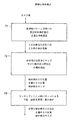
上述したように本発明を動作させるソフトウェアは図6に示される。これはループ内で動き、入力としてカメラから像を繰り返し取得し、スクリーン/投影像の内容を更新する。フローチャートに示されるように、このソフトウェアはカメラ像の入力とスクリーン/投影像の更新との間で4つの主要なステップを実行する。 The software for operating the present invention as described above is shown in FIG. It moves in a loop, repeatedly acquiring images from the camera as input and updating the contents of the screen / projection image. As shown in the flow chart, the software performs four main steps between camera image input and screen / projection image update.
第1のステップ61は投影された球体像の位置及びサイズの正確な検出であり、この球体像はほぼ円形の境界をもつ縞状あるいはリング状のパターンの外観を有している。目視されたこれらの縞の形状は平行な直線から楕円へ、更に同心円へと変化する(上述した図3及び図4の記載参照)。カメラ像における投影された北極の位置はこれらの縞パターンを用いて検出される。
The
第2のステップ62では、ソフトウェアはカメラに対する実際の球体の正確な中心3D位置及び球体の定位を計算するために2D(2次元)情報を使用する。上述したように、球体までの距離は球体像のサイズとカメラからの球体の距離との関係によって決定される。したがってこのサイズ決定はカメラの光学軸線の方向における球体までの距離を計算するのに使用される。左/右及び上/下方向のカメラ像における球体像の位置は3Dでのカメラに対する垂直あるいは水平方向における球体の位置を与える。3Dでの定位は球体像の外縁に対する投影された北極の位置から計算される。
In a
第3のステップ63では、カメラに対するペンの先端の実際の位置が計算される。球体中心の定位及び位置がここで知れたので、球体の極を通ってかつ取り付けられたペンを通して延びる軸線も当然知ることができる。ペン先端の位置は、球体の半径を加えたペンの長さに等しい球体中心からの距離にある軸線上の点として計算される。ペンの先端が壁面に触れない場合には、軸線が壁面と交差する点が計算される。両方の場合とも、壁の表面に存在する点が計算されそして次のステップへ出力する。
In a
第4のステップでは、ペンが指し示す投影像における実際の画素が特定される。最初の較正から、カメラ座標における壁面上の点が実際の投影像における画素座標とどのように関係するかが知られる。この情報に基づく簡単な数学的変換によって画素座標が計算される。画素のカラー/密度が修正された後は、もしユーザが描画し、あるいはユーザが画素の位置でボタンをクリックしようとするならば、マウスのクリックが同じ機能を動かせるのと同様にして、ウィンドウズシステムにおける適当な操作機能が呼び出される。 In the fourth step, the actual pixel in the projection image pointed to by the pen is specified. From the initial calibration it is known how the points on the wall in camera coordinates relate to the pixel coordinates in the actual projection image. Pixel coordinates are calculated by a simple mathematical transformation based on this information. After the pixel color / density has been modified, if the user draws, or if the user tries to click the button at the pixel location, the Windows system can do the same as a mouse click can move the same function The appropriate operating function in is called.
上述したように、照明(及び、したがってパターンの像)をオン及びオフに切り替えるペンのボタン押下げがマウスボタンの機能を模倣するのに使用される。ボタンが押されると、パターンが現われ、そしてパターンの位置が決定され、対応するスクリーンの位置で「マウスクリック」が有効となる。もしボタンが押されないと、ペンの位置は検出されない。これは、ボタンが押し下げられない時にペンがどこを指し示しているかに関してユーザがガイドを必要とする応用例においてのみ問題となるに過ぎない。ダブルクリック、左クリック、右クリック等のようなより複雑なクリック情報は、もし対応するボタンが押されるならば、予め限定された方法でパターンをオン、オフに切り替える内蔵された符号化によって伝達される。これとは別に、カメラの異なったカラーチャンネルの使用及び特別なカラーチャンネルのみの照明を増大する周波数のLEDの使用が可能となる(上述の通り)。 As described above, pen button depressions that switch the illumination (and thus the pattern image) on and off are used to mimic the function of a mouse button. When the button is pressed, the pattern appears and the position of the pattern is determined and "mouse click" is activated at the corresponding screen position. If the button is not pressed, the pen position is not detected. This is only a problem in applications where the user needs a guide as to where the pen is pointing when the button is not depressed. More complex click information such as double-click, left-click, right-click, etc. is conveyed by built-in coding that switches the pattern on and off in a limited way if the corresponding button is pressed. The Apart from this, it is possible to use different color channels of the camera and LEDs with frequencies that increase the illumination of only the special color channels (as described above).
上述したように、ボタンが押されていない時にペンがどこを指し示しているかに関してユーザがガイドを必要とする場合、この機能はリバースされ、照明が常時オンとなりかつクリックによって照明がオフに切り替えられる(「パターン検出」状態から「パターン非検出」状態への切り替えに関して既に述べた通り)。 As mentioned above, if the user needs a guide as to where the pen is pointing when the button is not pressed, this function is reversed, the illumination is always on and the click switches the illumination off ( As described above regarding switching from the “pattern detection” state to the “pattern non-detection” state).
投影された球体像のパラメータが検出される速度、堅牢さ及び精密度はこのシステムの品質を決定する。図7のフローチャートはこの第1のステップを3つの詳しいステップに区分してより詳細に記述したものである。 The speed, robustness and precision with which the projected sphere image parameters are detected determine the quality of the system. The flowchart of FIG. 7 describes this first step in more detail by dividing it into three detailed steps.
第1のステップ71は、水平方向あるいは垂直方向のいずれかの直線状に連続する黒及び白のみを検出するコンピュータ処理による非常に速いサーチを用いる可能な候補位置の高速事前選択である(上述の通り)。これは候補位置のリストを出力する。
The
第2のステップ72では、すべての候補位置が更に調査され、そして最も近いものが選択される。この時点で、球体像の中心の位置のおおよその値、球体のサイズ及び球体像における投影された北極のおおよその位置が検出され、第3のステップへと出力される。
In a
第3のステップ73では、像(図2)のパターンと最もよく相関する人工的なパターン(例えば図1)のパラメータを見い出すことによって、上述した検出値がサブピクセル(サブピクセル)の精度まで精緻化される。球体像の中心の正確な値、球体像のサイズ及び投影された北極の位置がこの検出手順の結果として復帰する。
In the
いくつかの応用例では、ペン内に活性光源をもたないことが有利であり、これにより軽量化かつ小形化が可能となり、かつバッテリーの取換えの問題をなくすることができる。この場合、球体パターンは光反射物質及び光吸収物質の別の縞によって形成することができる。反射テープは明るい縞をつくるのに使用し得る1つの材料である。そのような材料は到来する方向の背後に光を反射する性質を有する。したがって、このパターンはカメラの隣に光源を置くことによって非常に明るく見えるようにすることができる。このようにぼやけを防ぐようにカメラの必要な露出を減少するという利点をなお享受できる。 In some applications, it is advantageous not to have an active light source in the pen, which can reduce weight and size, and eliminate the problem of battery replacement. In this case, the spherical pattern can be formed by another stripe of the light reflecting material and the light absorbing material. Reflective tape is one material that can be used to create bright stripes. Such materials have the property of reflecting light behind the direction of arrival. Therefore, this pattern can be made very bright by placing a light source next to the camera. Thus, the advantage of reducing the required exposure of the camera to prevent blurring can still be enjoyed.
可視光源が望ましくない場合には、赤外線光源及び明るい縞の赤外線スペクトルによく反射する物質を使用することができる。この形態においては、ペンのボタンが押された、あるいはペン先端が表面を触れたという情報は、外的作用によるものであるためパターンによって伝達されない。要求される機能性は、ジェスチャーによって、あるいは例えば既述したようにカメラのパターンの像を遮蔽し、また遮蔽を解くことによって(例えば、スプリング付勢のボタンを介して機械的に)、あるいは手で操作することによって実現される。 If a visible light source is not desired, an infrared light source and a material that reflects well in the bright fringe infrared spectrum can be used. In this form, the information that the button of the pen is pressed or the tip of the pen touches the surface is not transmitted by the pattern because it is due to an external action. The required functionality is either by gesture or by, for example, shielding and unmasking the camera pattern as described above (eg mechanically via a spring-loaded button) or by hand. It is realized by operating with.
別の実施例では、面自体をペンの先端と接触して伝達できることが予見できる。この場合、カメラはペンの位置及び/または定位をモニターするためにのみが必要であり、前記接触を決定するためには別の光源を使用する。これを実現する1つの方法は、スクリーンに高周波の交流充電を行いかつ連続的にその容量を測定することであり、−(例えば)メタルチップとの接触はスクリーンの測定容量に影響を与え、この容量変化の検出は前記接触が起きたことを示すことになる。 In another embodiment, it can be foreseen that the surface itself can be transmitted in contact with the tip of the pen. In this case, the camera only needs to monitor the position and / or orientation of the pen and uses another light source to determine the contact. One way to achieve this is to perform a high frequency AC charge on the screen and continuously measure its capacity,-contact with the metal chip (for example) affects the measured capacity of the screen, this Detection of a change in capacitance will indicate that the contact has occurred.
応用例によっては、赤外線感応カメラを必要とせずに、例えば改変されない(unmodified)ウェブカメラが使用できるように像の検出が達成される場合にはこれは利点となる。このシステムは同一原理で働くが、ただ可視LEDがペンに(あるいはカメラの近くに)配置される。この設定にではソフトウェアのパターン検出ステップはより混乱したバックグラウンドのパターンに対処するように必然的に適合される。この情況を改善しかつパターン検出を改善する1つの方法は、単純な黒と白のシークエンスの代わりに縞として変わった色のシークエンスを用いることである。ペンが何時壁面に触れたか、あるいはクリックが何時なされたかを示す情報は照明のオン及びオフの切り替えにより伝達される(活性光はペン内にある。)。 In some applications, this is an advantage if image detection is achieved without the need for an infrared sensitive camera, for example an unmodified web camera can be used. This system works on the same principle, but only a visible LED is placed on the pen (or near the camera). In this setting, the software pattern detection step is necessarily adapted to deal with more confusing background patterns. One way to improve this situation and improve pattern detection is to use a sequence of unusual colors as a stripe instead of a simple black and white sequence. Information indicating when the pen touches the wall surface or when a click is made is transmitted by turning the illumination on and off (active light is in the pen).
本発明の応用例は、典型的なマウスによって実現される2方向(上下、左右)に限定されているものに代わるものであり、価格水準及びワイヤレスマウスの人間工学的特性を享受でき、自由度6(3D空間における位置及び定位)のモニターを行う能力を提供するPCの一般的な入力装置に対するものである。 The application example of the present invention is an alternative to the one limited to the two directions (up and down, left and right) realized by a typical mouse, can enjoy the price level and the ergonomic characteristics of the wireless mouse, and has a degree of freedom. 6 for a general input device of a PC that provides the ability to monitor 6 (position and localization in 3D space).
上述した通り、前記装置はコンピュータゲームに対する入力あるいはコントロールデバイスとして使用される。これらのゲームは、例えば仮想砲撃(virtual gunfire)、仮想ラケット、野球バット、光サーベル、魔法杖、銃または限定された定位をもつ任意の仮想物体(本発明と関連する技術によって引き出される)である。ペンの正確な位置及び定位をリアルタイムに追跡できるので、前記ゲームは「マジックペン」を用いることによって現存のパッドタイプのゲームコントローラよりもプレーヤの動きに、より正確に応答することができる。 As described above, the apparatus is used as an input or control device for computer games. These games are, for example, virtual gunfire, virtual rackets, baseball bats, light sabers, magic wands, guns or any virtual object with limited orientation (drawn by techniques related to the present invention). . Since the exact position and orientation of the pen can be tracked in real time, the game can respond more accurately to player movements than existing pad-type game controllers by using a “magic pen”.
「マジックペン」は、予見され及び検討されて、壁面あるいは他の適当な面上のデジタル投影器によって投影された像の中にマウスクリックを書き込むか、マウスクリックを実現することができる。これによりデジタル投影器を使用するプレゼンテーションをより会話的なものにすることができ、プレゼンター(発表者)は聴衆に対面している間にペンを使用して、ウェブページ間を概観する(ざっと目を通す)、あるいはリアルタイムでの物体やハイライトテキストなどを操作するのと同一の方法でスライドからスライドへと目を通しながら投影像の中に埋め込まれた種々のリンクを作動させることができる。 A “magic pen” can be foreseen and considered to write or implement a mouse click in an image projected by a digital projector on a wall or other suitable surface. This makes presentations using digital projectors more conversational, and presenters (presenters) use a pen while facing the audience to get an overview of the web pages (roughly look at them). Various links embedded in the projected image can be activated while looking through the slides in the same way as manipulating objects, highlight text, etc. in real time.
「マジックペン」は、そのペンの検出が投影像中に仮想的に描くか書き込むのに充分なほど正確なので、投影された像を白板(ホワイトボード)として機能させることができる。描画のためには、マジックペンは塗料散布デバイスのように動作することもできる。ペンの正確な位置及び定位は、そのペンが実際に壁面に触れていない時でも計算することができ、散布された塗料の軌跡(path)は3Dで計算され、また仮想の塗料が正しい位置に現われるようにできる。塗料の拡がりは塗料散布デバイスの拡がりに合致するように、例えば、より広くなればペンの先端が壁面からより離れるように調整することもできる。マジックペンが描画/書込み/散布をする色をユーザが変えたいときは、塗料ブラシに似た形態でそれを使用することができる。すなわち、壁面上に表示された仮想のカラーパレット上の仮想のカラー小片(patches)中に漬けることができる。 Since the “magic pen” is sufficiently accurate that the detection of the pen is virtually drawn or written in the projected image, the projected image can function as a white board. For drawing, the magic pen can also behave like a paint spraying device. The exact position and orientation of the pen can be calculated even when the pen is not actually touching the wall, the sprayed paint path is calculated in 3D, and the virtual paint is in the correct position. Can appear. The spread of the paint can be adjusted so as to match the spread of the paint spraying device, for example, so that the tip of the pen can be further away from the wall surface as it becomes wider. If the user wants to change the color that the magic pen draws / writes / spreads, it can be used in a form similar to a paint brush. That is, it can be immersed in virtual color patches on a virtual color palette displayed on the wall.
マジックペンの応用例では、PDA(携帯情報端末)にあるいは携帯電話機のような移動体デバイス用の入力法となるように縮小することもできる。現代の携帯電話機及びPDAの代表例はカメラを含んでおり、また実際、組込み投影器を備えたプロトタイプのPDAは本出願の時点で既に知られている。 In an application example of a magic pen, the input method can be reduced to a PDA (personal digital assistant) or a mobile device such as a mobile phone. Typical examples of modern mobile phones and PDAs include cameras, and in fact, prototype PDAs with built-in projectors are already known at the time of this application.
移動体デバイスに特定の1つの問題は、埋込まれる任意の入力及び出力装置が必然的に小形でなければならず、結果としてその有用性が抑制されることである。図13はマジックペンが機能的にPDA131に拡張された本発明の実施例を示すものである。この例のPDAは明るい表面色もつテーブル上面133上に配置され、組込み形の投影器134が像135をテーブル上面133上のラフなサイズの紙シートあるいはコンピュータに投影する。適切にデザインされたマジックペンあるいはマジックペンタイプのスタイラス139を備えたこの装置のカメラ137は投影像135に書き込んだり描画したりするのに使用され、あるいはマウスをクリックして(あるいはスタイラスを打ち付けて)PDA131のユーザインターフェイスを制御できるようにしている。充分なコンピュータ的なパワー、メモリ及びインターネット接続性によって自分のポケットのまわりに完全に機能的なオフィスを携行しかつテーブル及び椅子のある所にはどこでもこれを据えることができる。
One problem specific to mobile devices is that any input and output devices that are embedded must necessarily be small, resulting in limited usefulness. FIG. 13 shows an embodiment of the present invention in which the magic pen is functionally extended to the
投影器134と表面133との距離が短いこと、及び投影が表面上に投射される垂直面に対する角度が大きいことに起因して、強い基礎的な補正が必要である。しかしながら、投影の位置及び方向を注意深く選ぶことにより、投影の主要な問題(すなわち、マジックペンまたはスタイラスを手動操作することによって不明瞭になるという問題)は除去することができる。図13に示すように、ペン/スタイラス139(及び手に保持したそのもの)は、どんな場合でも不明瞭となる領域138が像135である場合、例えば、ハードコピーまたはタッチスクリーンディスプレイは別にして、投影の可視内容を不明瞭にしたり影にしたりすることはない。
Strong basic correction is required due to the short distance between the
本発明はまたテレビジョン93用の最新のリモートコントローラ91に組み入れることができる。このコントローラは離れた場所からテレビスクリーン93上の異なった位置を指し示すことができ、より感覚的にメニューの選択を行い、かつマウスクリックよりもむしろ「マジックペン」のクリックを介してソファから(例えば)ワード・ワイド・ウェブ(www)上をざっと目を通すことができる。このことは図9に模型的に示されている。
The present invention can also be incorporated into a modern
別の応用例は、感覚的に使用し易い、ステアリングインターフェイスあるいはコントローリングインターフェイスである。この装置はロボットアーム、掘削機あるいは類似の機械、あるいは玩具を制御するために使用される。アームのエフェクターは本発明により測定されたような手持ち式の入力装置の位置及び定位にしたがって位置及び定位を変更するように構成し得る。 Another application is a steering interface or a controlling interface that is easy to use sensuously. This device is used to control a robot arm, excavator or similar machine, or a toy. The arm effector may be configured to change position and orientation according to the position and orientation of the handheld input device as measured by the present invention.
他の関連する応用例は、仮想のコントロールセンター用のものである。ペンはダイヤル及びボタンの全配列を表わすことができ、3d(3次元)空間内のペンを保持する場所に依存して、異なるダイヤルを調整し、あるいは特定のボタンを働かせることができる。ダイヤルのセッティングを変えることはペンの再方向付け(reorienting)によって実現される。 Another related application is for a virtual control center. The pen can represent the entire arrangement of dials and buttons, and different dials can be adjusted or specific buttons can be activated depending on where the pen is held in 3d (three-dimensional) space. Changing the dial settings is achieved by reorienting the pen.
他の応用例はジェスチャー認識用のものである。本発明は3D空間内のペンの実際の軌道を検出できるので、コンピュータは機械や器具を制御するのに用いられる、指示をするジェスチャー(pointing gesture)、合図するジェスチャー(waving gesture)、空中などに大きな文字あるいは記号を書くことを認識することができる。「マジック杖」の機能は、機械の制御から仮想世界における物体の制御まで、多くのHCI(ヒューマンコンピュータインターフェイス)を商用上利用可能にし、玩具及びゲームに大いに応用できる。 Another application is for gesture recognition. Since the present invention can detect the actual trajectory of the pen in 3D space, the computer can be used to control machines and instruments, such as pointing gestures, waving gestures, in the air, etc. Recognize writing large letters or symbols. The “magic wand” function makes many HCIs (Human Computer Interfaces) commercially available, from machine control to object control in the virtual world, and can be applied to toys and games.
一つまたは複数の球体は、例えば機械、ロボット、人間、動物などの動く部分の適当なところにも配置でき、監視カメラにより種々の動作部がどこにあるかを知ることができ、またそれらがそれら自身の位置及び定位(position and orientation)に関してどのように定位するかを、対応する球体の位置及び定位を決定することによって知ることができる。
これはゲーム用の動作把握技術に応用でき、また一点の装置のリアルタイムの動きを図示するコンピュータモデルを作成することもでき、また適当なフィードバックの配置構成を有する装置を制御するのにも有用である。
One or more spheres can be placed at appropriate places in moving parts such as machines, robots, humans, animals, etc., and the surveillance camera can know where the various moving parts are, and they can be How to localize with respect to its position and orientation can be known by determining the position and orientation of the corresponding sphere.
This can be applied to motion grasping technology for games, can create a computer model that illustrates the real-time movement of a single device, and is useful for controlling a device with an appropriate feedback arrangement. is there.
アタッチメントの球体は空中に放り投げたり、表面にバウンドさせることができ、その正確な軌道及び回転を検出できる。これは球体が動く媒体についての詳細な情報、例えば粘度、気流の乱れ等々の情報を集めるのに有用である。球体が面から跳ね返える様子から面の幾何学的形状、動き、または弾性を計算するのに使用できる。 The attachment sphere can be thrown into the air or bounced to the surface, and its exact trajectory and rotation can be detected. This is useful for gathering detailed information about the medium on which the sphere moves, such as viscosity, air turbulence, and the like. Can be used to calculate surface geometry, motion, or elasticity from how a sphere bounces off the surface.
図11及び図12を参照して、正確さの要求及び如何にしてそれらが満たされるかを検討する。 Referring to FIGS. 11 and 12, consider the accuracy requirements and how they are met.
ウェブカメラなどの標準カメラを使用することにより、ビデオフレームレートで達成される解像度はカメラ像の幅にわたって約640画素である。投影像内の有効な書き込み領域は1メートルのオーダである。カメラの視野をこの領域に合致するように調整するとすると、カメラ像の単一画素の幅はしたがってスクリーン上で1.5mm以上の距離に相当する。 By using a standard camera such as a webcam, the resolution achieved at the video frame rate is approximately 640 pixels across the width of the camera image. The effective writing area in the projected image is on the order of 1 meter. If the camera field of view is adjusted to match this region, the single pixel width of the camera image thus corresponds to a distance of 1.5 mm or more on the screen.
人間工学的観点から、パターンを形成するマーカーは、そのパターンを形成するマーカーの直径がペンの長さの1/3を超えないように、ペンの背後から各方向にペンの全長の約1/6以上にしないことが適当である。 From an ergonomic point of view, the marker forming the pattern is approximately 1 / of the total length of the pen in each direction from the back of the pen so that the diameter of the marker forming the pattern does not exceed 1/3 of the pen length. It is appropriate not to make it 6 or more.
図12に示するように、最悪のケースでは、ペン先端が面を横切って距離Dだけずれるようにペンの定位を変えることはペンの背後のパターンが、Dの1/6であるdだけずれることを意味する。 As shown in FIG. 12, in the worst case, changing the orientation of the pen so that the pen tip moves across the surface by a distance D shifts the pattern behind the pen by d, which is 1/6 of D. Means that.
これは、1.5mm以下のペン先端の変位を検出するためにカメラ像におけるペンの背後でパターンのずれは1画素の1/6以上の解像度で検出する必要があることを意味する。もし有効な書き込み領域が1メートルでなく2メートルまで拡がるとすると、要求される解像度は1画素の1/2以上でなければならない。更に、これはカメラ像における或る量のノイズ及びぼやけに強力に対抗する態様で達成されなければならない。 This means that in order to detect the displacement of the pen tip of 1.5 mm or less, the pattern shift behind the pen in the camera image needs to be detected with a resolution of 1/6 or more of one pixel. If the effective writing area extends to 2 meters instead of 1 meter, the required resolution must be at least 1/2 pixel. Furthermore, this must be achieved in a manner that strongly counters a certain amount of noise and blur in the camera image.
パターンを形成する球体のアプローチは、特殊な同心円状で波様の帯状パターンをもつ単一の光散乱体(a single light diffusing pattern)を使用すること、及びカメラ像(例えば図2)における画素化された外観を連続的な(画素化されない)像空間のパラメータ化された連続する人工的パターンに整合させる方法によってこの球体の位置及び定位を引き出す方法を使用するところに特徴がある。 The sphere approach to patterning is to use a single light diffusing pattern with a special concentric, wavy strip pattern, and pixelation in the camera image (eg, FIG. 2) It is characterized by using this method of deriving the position and orientation of the sphere by a method that matches the rendered appearance to a parameterized continuous artificial pattern in continuous (non-pixelated) image space.
このアプローチの有効性は次の理由による。パターンがカメラ像内にかぶさる領域はペンの定位及び位置に無関係に常にはっきりした単一の円板(ディスク)状(あるいは若干楕円状)である。技術の熟練者は、像中の円板状物または円形物の検出を、この形状の単純性及び対称性によりアルゴリズム的に非常に容易かつ迅速に達成できることが理解できよう。 The effectiveness of this approach is due to the following reasons. The area that the pattern covers in the camera image is always a distinct single disc (or slightly oval) regardless of the orientation and position of the pen. Those skilled in the art will appreciate that the detection of discs or circles in an image can be accomplished very easily and quickly algorithmically due to the simplicity and symmetry of this shape.
球体形状は、また最大360°まで定位の形状範囲を拡張する。幾つかの既知システムで採用されている平坦なパターンは、その定位が90°変化したときカメラ視では直線に減少してしまう。この定位の拡張範囲は、使用中にペンの定位が垂直面から約+80°〜−80°の間の範囲で変化し得るので、ペンの応用例とって重要な要件であることに留意すべきである。 The spherical shape also extends the stereotactic range up to 360 °. The flat pattern employed in some known systems is reduced to a straight line when viewed from the camera when its orientation changes by 90 °. It should be noted that this extended range of orientation is an important requirement for pen applications, as the orientation of the pen can vary from about + 80 ° to −80 ° from the vertical plane during use. It is.
一般的に、定位の大きな検出範囲は広い範囲の定位で検出される物体にとって有利であるばかりでなく、装置をモニターするカメラを該装置に対して任意の角度で配置することができ、これはカメラが天井板から吊り下げられたり側壁近くに取り付けられたりするような応用例にとっても有利である。これはまた、閉塞(occulusion)や代理機能性(redundancy)に抗する機能を得るため数個のカメラによって異なる角度で検出する同装置の検出精度増大を可能とするものである。 In general, a large detection range of localization is not only advantageous for objects that are detected in a wide range of localization, but the camera that monitors the device can be placed at any angle with respect to the device, It is also advantageous for applications where the camera is suspended from the ceiling plate or mounted near the side wall. This also allows the detection accuracy of the device to be detected at different angles by several cameras to obtain a function that resists occlusion and redundancy.
球体の半透明部分は、その散光面がランベルト光源とほぼ同じなので曲率に関係なくカメラ像がすべて同等に明るく見える。これは面上の各点が全方向に同量のエネルギーを放射することを意味し、これによって球体が離れた光源から照らされた場合に想定されるような球状の影やハイライトがなくなる。その結果、球体はすべての方向からのカメラ像に平坦な円板として現われる。 The translucent part of the sphere has the same diffused surface as that of the Lambertian light source, so that all the camera images look equally bright regardless of the curvature. This means that each point on the surface radiates the same amount of energy in all directions, thereby eliminating the spherical shadows and highlights that would be expected when the sphere was illuminated from a distant light source. As a result, the sphere appears as a flat disk in the camera image from all directions.
光が遮断される球体表面上の領域は同様にカメラ像の円板上に一定の低い明度の領域を生じる。これは、球体上の帯縞が、円板像の表面をすべて横切って、安定した最小及び最大の明るさ及びその中間の安定した明度勾配をもつ低−高度の遷移状態を創出することを意味する。このことはパターンを検出するのに使用されるアルゴリズムの有効性を大きく改善する。 The area on the sphere surface where light is blocked results in a constant low brightness area on the disk of the camera image as well. This means that the stripes on the sphere create a low-to-high transition state with stable minimum and maximum brightness and a stable brightness gradient in between, all across the surface of the disc image. To do. This greatly improves the effectiveness of the algorithm used to detect the pattern.
位置及び定位情報を伝達するのに使用されるマーカー形状の直径は市場性と人間工学に沿ったものでなければならず、また手に持つ方式のデバイスは出来る限り小形で目立たないものにすべきである。球状のマーカーは特定の径を最大限にカバーし、画素の最大量をパターンに正確に合致させるために使用できるようにする。同時に球状の形は通常その対称性により審美的に最も好ましいものの1つと考えられる。 The diameter of the marker shape used to communicate position and localization information must be marketable and ergonomic, and the hand-held device should be as small and unobtrusive as possible It is. Spherical markers provide maximum coverage for a particular diameter and allow the maximum amount of pixels to be used to accurately match the pattern. At the same time, the spherical shape is usually considered one of the most aesthetically pleasing due to its symmetry.
サブピクセルの解像度については、高強度及び低強度の画素のみの位置の差からパターン位置を評価することは不充分であり、画素強度の実際の微細な変化から評価することも必要である。実際のパターンの小さなずれ(111〜113)が画素化された像中の対応する変化(115〜117)となる図11の例を参照されたい。人工的な連続パターン119が新たに検出された画素パターン117に適合されて、実際の新たなパターン113が決定される。
Regarding the resolution of the sub-pixel, it is not sufficient to evaluate the pattern position from the difference between the positions of only the high-intensity and low-intensity pixels, and it is also necessary to evaluate from the actual minute change in pixel intensity. See the example of FIG. 11 where a small deviation (111-113) of the actual pattern results in a corresponding change (115-117) in the pixelated image. The artificial
低−高度の遷移状態部分をカバーする画素は、画素位置が遷移状態の僅かに高い境界または低い境界にあるか否かに依存して、中間強度よりも僅かに高いかまたは低い強度を持つようである。このことは、分離している画素の強度値が連続的な空間内のパターンのサブピクセル位置についての情報を保持することを意味する。連続する規則的な波パターンの正確な位置は、それがサブピクセルであっても、適切に合致(マッチ)するアルゴリズムを用いてその画素化された等価物からリカバーできることを数学的に示すことができる。これは球体上にノイズのない完全なパターンが存在する場合の正確さを保証するものである。 Pixels that cover the low-to-high transition state portion appear to have a slightly higher or lower intensity than the intermediate intensity, depending on whether the pixel location is at a slightly higher or lower boundary of the transition state. It is. This means that the intensity values of the separated pixels retain information about the subpixel positions of the pattern in a continuous space. The exact location of a continuous regular wave pattern can mathematically indicate that even if it is a subpixel, it can be recovered from its pixelated equivalent using an algorithm that matches appropriately. it can. This guarantees accuracy when there is a complete pattern without noise on the sphere.
この方法は、マッチングアルゴリズムがパターンの拡張された領域中多くの縁部の重なった画素に存在するパターンのサブピクセル位置についての余剰の情報を使用できるので、ノイズの存在下でもなお正確さの良好なサブピクセルを与えることができる。ノイズによってもたらされるエラーはランダムなものであるから、それ自身多くの画素間で相殺する傾向があり、正確なパターン位置がなおリカバーされる。 This method is still accurate even in the presence of noise because the matching algorithm can use extra information about the sub-pixel position of the pattern that is present in many edge-overlapped pixels in the extended region of the pattern. Subpixels can be given. Since the error introduced by noise is random, it tends to cancel itself among many pixels, and the exact pattern position is still recovered.
ユーザが他のすべてを同じに保ちながらペンを長軸線のまわりに回転させると、ペンの先端は依然同じ位置を指し示す。したがってこの回転は本システムで対称性である。球体上の同心的な帯縞を使用することにより、ペンをその長軸線のまわりに回転したときにも変化しないパターンが創出される。パターンをこれらの回転に対して変化しないようにすることによって検出の計算は相当簡単になり、かつ数学的に一層安定となり、更に回転に無関係にペン先端に同じ3dの位置を生み出すことを明確に保証する。 If the user rotates the pen around the long axis while keeping everything else the same, the tip of the pen will still point to the same position. This rotation is therefore symmetric in the system. By using concentric strips on the sphere, a pattern is created that does not change when the pen is rotated around its long axis. By making the pattern not change with respect to these rotations, the detection calculation is considerably simpler and mathematically more stable, and it is clear that it produces the same 3d position at the pen tip regardless of rotation. Guarantee.
本明細書に開示した本発明は従来技術及び公知の「スマート」ボードなどを超える本質的な利点を有する。この「マジックペン」の技術は、単一のカメラ、及び特定の実施例においては、ペン先端が描画面に触れるとき赤外線で照明されるペンの後端の特殊なパターンを形成する球状のマーカー以外には、接触感応面またはその他の追加的な機器を必要とせずにユーザが投影像に自然に書き込むことを可能にする。照明されたパターンは投影器の近くの位置に配置されたカメラによってモニターされ、記録された像は投影器によって作られた像を改変するコンピュータ装置で解析される。ユーザは自分が書き込んだり描画したものを見るために投影器とペンとの間に自然に視線を向けるということが判明している。このことは、またパターン上のカメラによる視認を妨げることを自動的に避けることを意味する。カメラが投影器の近くに置かれている場合にはそのようにはならない。 The invention disclosed herein has substantial advantages over the prior art and known “smart” boards and the like. This “magic pen” technology is not a single camera and, in certain embodiments, a spherical marker that forms a special pattern at the back of the pen that is illuminated with infrared light when the pen tip touches the drawing surface. Allows the user to naturally write to the projected image without the need for a touch sensitive surface or other additional equipment. The illuminated pattern is monitored by a camera located near the projector, and the recorded image is analyzed by a computer device that modifies the image produced by the projector. It has been found that the user naturally turns his gaze between the projector and the pen to see what he has written or drawn. This also means that it automatically avoids obstructing viewing by the camera on the pattern. This is not the case when the camera is placed close to the projector.
典型的なスマートボードは双方向性を実現するため大形の接触感応スクリーンと投影像を組み合わせる。専用の電子機器をもつ拡張した固定のボードはこの解決を高価で扱いにくいものにする。本発明を実施するためには高価な機器を必要としないので、この技術は非常に節減された価格で、かつ非常に簡単な設備及びメンテナンスで利用できる。 A typical smart board combines a large touch-sensitive screen with a projected image to achieve interactivity. Extended fixed boards with dedicated electronics make this solution expensive and cumbersome. Since no expensive equipment is required to implement the present invention, this technology is available at a very reduced price and with very simple equipment and maintenance.
コストの節減及び高価なバードウェアの追加が不要であることのほか、そのようなスマートボードに比べた「マジックペン」の他の利点は、ペンの位置及び定位が、たとえそれが面に接触していなくても知り得るということである。このように、本発明は塗料の衝突位置、衝突角度及びスプレイコーンと面との交点を正確に決定できるので、スプレイガンをシミュレーションするのにも使用できる。 In addition to cost savings and the addition of expensive birdware, other advantages of the “magic pen” over such smartboards are that the pen's position and orientation, even if it touches the surface. You can know even if you don't. As described above, the present invention can accurately determine the collision position, the collision angle, and the intersection between the spray cone and the surface of the paint, so that it can be used to simulate a spray gun.
本発明は上述の「マジックペン」及びスプレイガンの応用例において大きな利点を有するが、これらに限定されるものではない。最も一般的な意味で本発明は新規な6自由度のリアルタイムコンピュータ入力デバイスを提供するものであり、3次元空間内の位置を特定する装置の自由な動き及び回転を正確に追跡することを可能にする。最も注目すべき他の応用例は、装置が仮想の刀剣、楯、野球バット、魔法杖、銃等々を表現するのに使用されるコンピュータゲームである。 The present invention has significant advantages in the aforementioned “magic pen” and spray gun applications, but is not limited thereto. In the most general sense, the present invention provides a new six-degree-of-freedom real-time computer input device that can accurately track the free movement and rotation of a device that locates in three-dimensional space. To. The other most notable applications are computer games where the device is used to represent virtual swords, spears, baseball bats, magic wands, guns, and so on.
本発明の一般的な利点は,マーカー上のパターンから獲得できる情報の量及び速さにある。完全3d位置及び3d定位が少なくとも標準ウェブカメラの機能性を持つ標準のPCハードウェア上のビデオフレームレートで決定され、追加的な情報ビット(例えば、赤外線照射との接触)によりマウスクリックする。また第2のパターンにコード化された少なくとも3ビットを実現できる可能性がある。情報が獲得される速度、正確さ及び範囲は、「マジックペン」応用例を正規のホワイトボードマーカーの操作と顕著な差がないように作動させるのに充分なものである。 The general advantage of the present invention is the amount and speed of information that can be obtained from the pattern on the marker. Full 3d position and 3d localization are determined by the video frame rate on standard PC hardware with at least standard web camera functionality and mouse clicks with additional information bits (eg, contact with infrared illumination). There is also a possibility that at least 3 bits encoded in the second pattern can be realized. The speed, accuracy and range at which information is acquired is sufficient to operate the “magic pen” application so that there is no significant difference from the operation of a regular whiteboard marker.
カメラの光学的限界及びその解像度の限界によって限定される範囲内で、この方法完完璧につくられたパターンを持つノイズの無いケースについて理論上任意の正確さで定位及び位置を検出することを可能にする。これはカメラ像中のパターンの画素化された表現にかかわらず当てはまることである(例えば、図2及び11、及び上記の関連する記載参照)。この限界範囲内において3回転軸の少なくとも2軸のまわりで完全に360°まで定位を検出できる。第3の軸(すなわち、ペンの長さ方向の軸)周囲の回転は第2のパターンを用いて決定される。 Within the range limited by the optical limits of the camera and its resolution limits, this method can detect the localization and position with theoretically arbitrary accuracy for a noiseless case with a perfectly created pattern. To. This is true regardless of the pixelated representation of the pattern in the camera image (see, eg, FIGS. 2 and 11 and the related description above). Within this limit range, the localization can be detected up to 360 ° around at least two of the three rotation axes. Rotation around the third axis (ie, the pen length axis) is determined using the second pattern.
パターンを形成されたマーカーは小サイズの軽量につくることができ、また審美的で人間工学的な外観を有する。上記詳しく検討した通り、マーカー自体は軽量な材料からなる中空球体とすることができる。 Patterned markers can be made small and lightweight, and have an aesthetic and ergonomic appearance. As discussed in detail above, the marker itself can be a hollow sphere made of a lightweight material.
本発明は、また固有の拡張性に基づく重要な利点を有する。例えば、数個の標準カメラ、またはマーカーが取り扱われるよりも広い範囲をモニターする視野のより広い単一の高解像度カメラを組み合せることによって、検出範囲が比較的容易に拡張される。複数のパターンを形成する球体は、それらが第2のパターンを用いる別々の装置とし取り扱うことができるので、それらは同時に容易に使用される。このことは、投影像のサイズを投影器とスクリーン間の距離を単に増加することによって容易に拡大できるため「マジックペン」の具体例の大きな利点となる。これにより、数人の人/子供が大きな面に同時に描画することを想定するような他の応用も可能となる。 The present invention also has important advantages based on inherent scalability. For example, the detection range can be extended relatively easily by combining several standard cameras or a single high resolution camera with a wider field of view that monitors a wider range than the marker is handled. Spheres that form multiple patterns can be handled as separate devices using the second pattern, so they are easily used simultaneously. This is a significant advantage of the “magic pen” embodiment because the size of the projected image can be easily increased by simply increasing the distance between the projector and the screen. This also allows other applications that assume several people / children are drawing simultaneously on a large surface.
上述した赤外線LEDを使用し、また赤外線LEDを接触作動させる装置は、動力消費量が低く、したがってバッテリー寿命が長い。更に、そのような装置は部材を容易に入手できまた製品の構成がシンプルであるが故に、低コストで製造できる。 A device that uses the infrared LED described above and operates the infrared LED in a contact manner has a low power consumption and therefore a long battery life. Further, such a device can be manufactured at low cost because the members are readily available and the construction of the product is simple.
要約すれば、本発明は単一の低コストのウェブカメラ及び極めて簡単なパターンをもつ単一の球体を用いて実行できる。コンピュータ上での本方法の実行はラムやハードディスクスペースのようなコンピュータ上のリソース(情報資源)の要求は低く、適度な処理速度のみが要求される。 In summary, the present invention can be implemented using a single low cost webcam and a single sphere with a very simple pattern. Execution of this method on a computer requires low resources (information resources) on the computer such as a ram and a hard disk space, and requires only an appropriate processing speed.
本発明のシステムの重要な利点は以上に記載した通りであり、コスト及び多用途性(versatility)の点から他のインターフェイスデバイスを超える機能性及び応用性を有する。本発明は複雑な電子機器や超音波センサ/レシーバ、接触感応面などを必要とせず、既製の大量生産されているウェブカメラ(赤外線用途用)を使用できる。インターフェイス装置自体は低コストであり、卓球のボール(このボールから本発明の実施例が作成できる。)及び赤外線LEDはすべて安価に購入できる。 The key advantages of the system of the present invention are as described above and have functionality and applicability over other interface devices in terms of cost and versatility. The present invention does not require complex electronic equipment, ultrasonic sensors / receivers, touch sensitive surfaces, etc., and can use ready-made mass-produced webcams (for infrared applications). The interface device itself is low cost, and table tennis balls (from which the embodiments of the present invention can be made) and infrared LEDs can all be purchased at low cost.
本発明の上述の記載は例示と説明のためのものであり、説明は完全なものではなく、また開示した内容そのものに本発明が限定されるものではない。記載した具体例は本発明の原理及びその実際上の応用を最もよく説明するために選ばれ、かつ記載されたものであり、これによって当該分野の技術者は本発明を意図する特定の用途に適合するように種々の具体例において、また種々の改変を行ってベストに利用することができる。したがって、添付の特許請求の範囲により定義された本発明の範囲から逸脱することなく更なる変形あるいは改良を具体化することができる。例えば、一連の帯縞を含むものとして詳細に記載した球体に関しては、任意の認識可能な表面パターンが適用できる。更に、改変したウェブカメラの有利な具体例について記載したが、任意の適当なカメラ、例えば専用の高解像度赤外線結像カメラが使用可能である。 The above description of the present invention has been presented for purposes of illustration and description, and is not intended to be exhaustive or to limit the invention to the precise content disclosed. The described embodiments have been chosen and described in order to best explain the principles of the invention and its practical application, so that those skilled in the art have the specific application for which the invention is intended. Various modifications can be made to suit, and various modifications can be made to make the best use. Accordingly, further modifications or improvements may be embodied without departing from the scope of the invention as defined by the appended claims. For example, any recognizable surface pattern can be applied to a sphere described in detail as including a series of strips. Furthermore, although an advantageous embodiment of a modified web camera has been described, any suitable camera, such as a dedicated high resolution infrared imaging camera, can be used.
1 インターフェイス装置
3 カメラ
5 ペン
7 球体
9 赤道(equator)
11 リング
13 北極
15 南極
17 バッテリー
19 LED
21,23 ボタン
25 放物面鏡
27 投影像
29 センサチップ
31 実像
33 コンピュータ
35 デジタル投影器
37 投影面
39 較正パターン
41 カメラ像
43 イリュージョン
91 リモートコントローラ
93 テレビスクリーン
131 PDA
133 テーブル上面
134 投影器
135 像
137 カメラ
138 不明瞭領域
139 スタイラス
1
11
21, 23
133 Table
Claims (95)
物体の1つまたはそれ以上の像を作り出す結像手段と、
1つまたはそれ以上の像におけるパターンを形成するマーカーの外観から空間内の物体の位置及び定位(orientation)を計算する像処理手段とを有することを特徴とする物体の位置及び定位検出システム。 An object having a marker that forms a pattern with a detectable pattern at least a portion of the object disposed on;
Imaging means for creating one or more images of the object;
An object position and localization detection system comprising image processing means for calculating the position and orientation of an object in space from the appearance of a marker forming a pattern in one or more images.
1つまたはそれ以上の像におけるパターンを形成するマーカーの外観から空間中の物体の位置及び定位を計算する工程とを有することを特徴とする物体の位置及び定位検出装置を作動する方法。 Obtaining one or more object images having markers forming a pattern with a detectable pattern at least a portion of the object disposed on the object;
Calculating an object position and localization in space from the appearance of a marker that forms a pattern in one or more images.
(a)ディスプレイ上に較正像を設ける工程と、
(b)結像手段を使用して較正像を検出する工程と、
(c)前記較正像と検出された較正像との間のマッピングを決定する工程とを有することを特徴とする較正方法。 A method for calibrating an object position and localization detection system according to any of claims 1 to 32 having a corresponding display comprising:
(A) providing a calibration image on the display;
(B) detecting a calibration image using imaging means;
(C) determining a mapping between the calibration image and the detected calibration image.
(i)前記較正像に複数個の較正マーカーを与える工程と、
(ii)前記較正像における複数個の較正マーカーの位置と検出された較正像における複数個の較正マーカーの位置とを比較する工程とを有する請求項83に記載の較正方法。 Determining a mapping between the calibration image and the detected calibration image;
(I) providing a plurality of calibration markers on the calibration image;
84. The calibration method according to claim 83, further comprising: (ii) comparing positions of a plurality of calibration markers in the calibration image with positions of the plurality of calibration markers in the detected calibration image.
(a)ディスプレイ上に像を供給する工程と、
(b)結像デバイスを用いて像を検出する工程と、
(c)前記結像デバイスから生じたディスプレイ上の仮想投影に対応してディスプレイ上に副像を供給する工程とを有することを特徴とする結像デバイスを整列する方法。 A method for aligning an imaging device of an object position and localization detection system comprising:
(A) supplying an image on the display;
(B) detecting an image using an imaging device;
And (c) providing a sub-image on the display in response to a virtual projection on the display resulting from the imaging device.
Applications Claiming Priority (2)
| Application Number | Priority Date | Filing Date | Title |
|---|---|---|---|
| GBGB0622451.3A GB0622451D0 (en) | 2006-11-10 | 2006-11-10 | Object position and orientation detection device |
| PCT/GB2007/004319 WO2008056180A2 (en) | 2006-11-10 | 2007-11-12 | Object position and orientation detection system |
Publications (2)
| Publication Number | Publication Date |
|---|---|
| JP2010509582A true JP2010509582A (en) | 2010-03-25 |
| JP2010509582A5 JP2010509582A5 (en) | 2014-04-03 |
Family
ID=37594702
Family Applications (1)
| Application Number | Title | Priority Date | Filing Date |
|---|---|---|---|
| JP2009535809A Pending JP2010509582A (en) | 2006-11-10 | 2007-11-12 | Object position and localization detection system |
Country Status (6)
| Country | Link |
|---|---|
| US (1) | US9536163B2 (en) |
| EP (4) | EP2175229A1 (en) |
| JP (1) | JP2010509582A (en) |
| CA (1) | CA2705346A1 (en) |
| GB (1) | GB0622451D0 (en) |
| WO (1) | WO2008056180A2 (en) |
Cited By (4)
| Publication number | Priority date | Publication date | Assignee | Title |
|---|---|---|---|---|
| JP2011185886A (en) * | 2010-03-11 | 2011-09-22 | Nec Corp | System and method for calculating reference position |
| KR101403915B1 (en) | 2013-03-25 | 2014-06-09 | 한국도로공사 | Camera mounting apparatus for structure checking and system for structure checking having the same |
| WO2019181118A1 (en) * | 2018-03-23 | 2019-09-26 | 株式会社ワコム | Three-dimensional pointing device and three-dimensional position detection system |
| JP2019215378A (en) * | 2013-04-30 | 2019-12-19 | コー・ヤング・テクノロジー・インコーポレーテッド | Method for operating optical tracking system and optical tracking system |
Families Citing this family (155)
| Publication number | Priority date | Publication date | Assignee | Title |
|---|---|---|---|---|
| US8797260B2 (en) | 2002-07-27 | 2014-08-05 | Sony Computer Entertainment Inc. | Inertially trackable hand-held controller |
| US7646372B2 (en) | 2003-09-15 | 2010-01-12 | Sony Computer Entertainment Inc. | Methods and systems for enabling direction detection when interfacing with a computer program |
| US9393487B2 (en) | 2002-07-27 | 2016-07-19 | Sony Interactive Entertainment Inc. | Method for mapping movements of a hand-held controller to game commands |
| US9474968B2 (en) | 2002-07-27 | 2016-10-25 | Sony Interactive Entertainment America Llc | Method and system for applying gearing effects to visual tracking |
| US7760248B2 (en) | 2002-07-27 | 2010-07-20 | Sony Computer Entertainment Inc. | Selective sound source listening in conjunction with computer interactive processing |
| US8019121B2 (en) | 2002-07-27 | 2011-09-13 | Sony Computer Entertainment Inc. | Method and system for processing intensity from input devices for interfacing with a computer program |
| US8313380B2 (en) | 2002-07-27 | 2012-11-20 | Sony Computer Entertainment America Llc | Scheme for translating movements of a hand-held controller into inputs for a system |
| US8570378B2 (en) | 2002-07-27 | 2013-10-29 | Sony Computer Entertainment Inc. | Method and apparatus for tracking three-dimensional movements of an object using a depth sensing camera |
| US9682319B2 (en) | 2002-07-31 | 2017-06-20 | Sony Interactive Entertainment Inc. | Combiner method for altering game gearing |
| US7647197B2 (en) * | 2002-08-09 | 2010-01-12 | Surveylab Group Limited | Mobile instrument, viewing device, and methods of processing and storing information |
| US9177387B2 (en) | 2003-02-11 | 2015-11-03 | Sony Computer Entertainment Inc. | Method and apparatus for real time motion capture |
| US8072470B2 (en) | 2003-05-29 | 2011-12-06 | Sony Computer Entertainment Inc. | System and method for providing a real-time three-dimensional interactive environment |
| US10279254B2 (en) | 2005-10-26 | 2019-05-07 | Sony Interactive Entertainment Inc. | Controller having visually trackable object for interfacing with a gaming system |
| US9573056B2 (en) | 2005-10-26 | 2017-02-21 | Sony Interactive Entertainment Inc. | Expandable control device via hardware attachment |
| US7663689B2 (en) | 2004-01-16 | 2010-02-16 | Sony Computer Entertainment Inc. | Method and apparatus for optimizing capture device settings through depth information |
| US8547401B2 (en) | 2004-08-19 | 2013-10-01 | Sony Computer Entertainment Inc. | Portable augmented reality device and method |
| US8427426B2 (en) | 2005-05-27 | 2013-04-23 | Sony Computer Entertainment Inc. | Remote input device |
| US7548230B2 (en) | 2005-05-27 | 2009-06-16 | Sony Computer Entertainment Inc. | Remote input device |
| US8210943B1 (en) | 2006-05-06 | 2012-07-03 | Sony Computer Entertainment America Llc | Target interface |
| US8781151B2 (en) | 2006-09-28 | 2014-07-15 | Sony Computer Entertainment Inc. | Object detection using video input combined with tilt angle information |
| US8310656B2 (en) | 2006-09-28 | 2012-11-13 | Sony Computer Entertainment America Llc | Mapping movements of a hand-held controller to the two-dimensional image plane of a display screen |
| USRE48417E1 (en) | 2006-09-28 | 2021-02-02 | Sony Interactive Entertainment Inc. | Object direction using video input combined with tilt angle information |
| US9526995B2 (en) | 2006-11-22 | 2016-12-27 | Sony Interactive Entertainment America Llc | Video game recording and playback with visual display of game controller manipulation |
| CN102016877B (en) | 2008-02-27 | 2014-12-10 | 索尼计算机娱乐美国有限责任公司 | Methods for capturing depth data of a scene and applying computer actions |
| FR2933511A1 (en) * | 2008-07-04 | 2010-01-08 | Optinnova | INTERACTIVE VISUALIZATION DEVICE AND METHOD USING DETECTION CAMERA AND OPTICAL POINTER |
| US8342926B2 (en) | 2008-07-13 | 2013-01-01 | Sony Computer Entertainment America Llc | Game aim assist |
| US9482755B2 (en) | 2008-11-17 | 2016-11-01 | Faro Technologies, Inc. | Measurement system having air temperature compensation between a target and a laser tracker |
| US8253801B2 (en) | 2008-12-17 | 2012-08-28 | Sony Computer Entertainment Inc. | Correcting angle error in a tracking system |
| US8761434B2 (en) | 2008-12-17 | 2014-06-24 | Sony Computer Entertainment Inc. | Tracking system calibration by reconciling inertial data with computed acceleration of a tracked object in the three-dimensional coordinate system |
| US9058063B2 (en) | 2009-05-30 | 2015-06-16 | Sony Computer Entertainment Inc. | Tracking system calibration using object position and orientation |
| GB0920754D0 (en) | 2009-11-27 | 2010-01-13 | Compurants Ltd | Inamo big book 1 |
| US9264785B2 (en) | 2010-04-01 | 2016-02-16 | Sony Computer Entertainment Inc. | Media fingerprinting for content determination and retrieval |
| US8560583B2 (en) | 2010-04-01 | 2013-10-15 | Sony Computer Entertainment Inc. | Media fingerprinting for social networking |
| US9377885B2 (en) | 2010-04-21 | 2016-06-28 | Faro Technologies, Inc. | Method and apparatus for locking onto a retroreflector with a laser tracker |
| US8537371B2 (en) | 2010-04-21 | 2013-09-17 | Faro Technologies, Inc. | Method and apparatus for using gestures to control a laser tracker |
| US8619265B2 (en) | 2011-03-14 | 2013-12-31 | Faro Technologies, Inc. | Automatic measurement of dimensional data with a laser tracker |
| US8724119B2 (en) | 2010-04-21 | 2014-05-13 | Faro Technologies, Inc. | Method for using a handheld appliance to select, lock onto, and track a retroreflector with a laser tracker |
| US9772394B2 (en) | 2010-04-21 | 2017-09-26 | Faro Technologies, Inc. | Method and apparatus for following an operator and locking onto a retroreflector with a laser tracker |
| US8422034B2 (en) | 2010-04-21 | 2013-04-16 | Faro Technologies, Inc. | Method and apparatus for using gestures to control a laser tracker |
| US9400170B2 (en) | 2010-04-21 | 2016-07-26 | Faro Technologies, Inc. | Automatic measurement of dimensional data within an acceptance region by a laser tracker |
| US8602893B2 (en) * | 2010-06-02 | 2013-12-10 | Sony Computer Entertainment Inc. | Input for computer device using pattern-based computer vision |
| US9143699B2 (en) | 2010-07-13 | 2015-09-22 | Sony Computer Entertainment Inc. | Overlay non-video content on a mobile device |
| US9832441B2 (en) | 2010-07-13 | 2017-11-28 | Sony Interactive Entertainment Inc. | Supplemental content on a mobile device |
| US8730354B2 (en) | 2010-07-13 | 2014-05-20 | Sony Computer Entertainment Inc | Overlay video content on a mobile device |
| US9814977B2 (en) | 2010-07-13 | 2017-11-14 | Sony Interactive Entertainment Inc. | Supplemental video content on a mobile device |
| US9159165B2 (en) | 2010-07-13 | 2015-10-13 | Sony Computer Entertainment Inc. | Position-dependent gaming, 3-D controller, and handheld as a remote |
| US9746354B2 (en) | 2010-08-26 | 2017-08-29 | Blast Motion Inc. | Elastomer encased motion sensor package |
| US9396385B2 (en) | 2010-08-26 | 2016-07-19 | Blast Motion Inc. | Integrated sensor and video motion analysis method |
| US9622361B2 (en) * | 2010-08-26 | 2017-04-11 | Blast Motion Inc. | Enclosure and mount for motion capture element |
| US9406336B2 (en) | 2010-08-26 | 2016-08-02 | Blast Motion Inc. | Multi-sensor event detection system |
| US9626554B2 (en) | 2010-08-26 | 2017-04-18 | Blast Motion Inc. | Motion capture system that combines sensors with different measurement ranges |
| US9604142B2 (en) | 2010-08-26 | 2017-03-28 | Blast Motion Inc. | Portable wireless mobile device motion capture data mining system and method |
| US8903521B2 (en) | 2010-08-26 | 2014-12-02 | Blast Motion Inc. | Motion capture element |
| US9646209B2 (en) | 2010-08-26 | 2017-05-09 | Blast Motion Inc. | Sensor and media event detection and tagging system |
| US8994826B2 (en) | 2010-08-26 | 2015-03-31 | Blast Motion Inc. | Portable wireless mobile device motion capture and analysis system and method |
| US9401178B2 (en) | 2010-08-26 | 2016-07-26 | Blast Motion Inc. | Event analysis system |
| US9643049B2 (en) | 2010-08-26 | 2017-05-09 | Blast Motion Inc. | Shatter proof enclosure and mount for a motion capture element |
| US9039527B2 (en) | 2010-08-26 | 2015-05-26 | Blast Motion Inc. | Broadcasting method for broadcasting images with augmented motion data |
| US9076041B2 (en) | 2010-08-26 | 2015-07-07 | Blast Motion Inc. | Motion event recognition and video synchronization system and method |
| US9261526B2 (en) | 2010-08-26 | 2016-02-16 | Blast Motion Inc. | Fitting system for sporting equipment |
| US9940508B2 (en) | 2010-08-26 | 2018-04-10 | Blast Motion Inc. | Event detection, confirmation and publication system that integrates sensor data and social media |
| US8827824B2 (en) | 2010-08-26 | 2014-09-09 | Blast Motion, Inc. | Broadcasting system for broadcasting images with augmented motion data |
| US10254139B2 (en) | 2010-08-26 | 2019-04-09 | Blast Motion Inc. | Method of coupling a motion sensor to a piece of equipment |
| US9028337B2 (en) * | 2010-08-26 | 2015-05-12 | Blast Motion Inc. | Motion capture element mount |
| US8905855B2 (en) | 2010-08-26 | 2014-12-09 | Blast Motion Inc. | System and method for utilizing motion capture data |
| US9418705B2 (en) | 2010-08-26 | 2016-08-16 | Blast Motion Inc. | Sensor and media event detection system |
| US9607652B2 (en) | 2010-08-26 | 2017-03-28 | Blast Motion Inc. | Multi-sensor event detection and tagging system |
| US9235765B2 (en) | 2010-08-26 | 2016-01-12 | Blast Motion Inc. | Video and motion event integration system |
| US8944928B2 (en) | 2010-08-26 | 2015-02-03 | Blast Motion Inc. | Virtual reality system for viewing current and previously stored or calculated motion data |
| US8613676B2 (en) | 2010-08-26 | 2013-12-24 | Blast Motion, Inc. | Handle integrated motion capture element mount |
| US9247212B2 (en) | 2010-08-26 | 2016-01-26 | Blast Motion Inc. | Intelligent motion capture element |
| US9619891B2 (en) | 2010-08-26 | 2017-04-11 | Blast Motion Inc. | Event analysis and tagging system |
| US9033810B2 (en) * | 2010-08-26 | 2015-05-19 | Blast Motion Inc. | Motion capture element mount |
| US9320957B2 (en) * | 2010-08-26 | 2016-04-26 | Blast Motion Inc. | Wireless and visual hybrid motion capture system |
| US8941723B2 (en) | 2010-08-26 | 2015-01-27 | Blast Motion Inc. | Portable wireless mobile device motion capture and analysis system and method |
| US20130154929A1 (en) * | 2010-08-27 | 2013-06-20 | Sebastian Stopp | Multiple-layer pointing position determination on a medical display |
| US20130201285A1 (en) | 2010-10-07 | 2013-08-08 | Sony Computer Entertainment Inc. | 3-d glasses with illuminated light guide |
| US8830329B2 (en) | 2010-10-07 | 2014-09-09 | Sony Computer Entertainment Inc. | 3-D glasses with camera based head tracking |
| US20130218068A1 (en) | 2010-10-18 | 2013-08-22 | CardioSonic Ltd. | Therapeutics reservoir |
| US9566456B2 (en) | 2010-10-18 | 2017-02-14 | CardioSonic Ltd. | Ultrasound transceiver and cooling thereof |
| WO2012052924A1 (en) | 2010-10-18 | 2012-04-26 | CardioSonic Ltd. | Separation device for ultrasound element |
| US8696581B2 (en) | 2010-10-18 | 2014-04-15 | CardioSonic Ltd. | Ultrasound transducer and uses thereof |
| US9028417B2 (en) | 2010-10-18 | 2015-05-12 | CardioSonic Ltd. | Ultrasound emission element |
| US20120200667A1 (en) * | 2011-02-08 | 2012-08-09 | Gay Michael F | Systems and methods to facilitate interactions with virtual content |
| GB2518769A (en) | 2011-03-03 | 2015-04-01 | Faro Tech Inc | Target apparatus and method |
| WO2012141868A1 (en) | 2011-04-15 | 2012-10-18 | Faro Technologies, Inc. | Enhanced position detector in laser tracker |
| US9164173B2 (en) | 2011-04-15 | 2015-10-20 | Faro Technologies, Inc. | Laser tracker that uses a fiber-optic coupler and an achromatic launch to align and collimate two wavelengths of light |
| US9686532B2 (en) | 2011-04-15 | 2017-06-20 | Faro Technologies, Inc. | System and method of acquiring three-dimensional coordinates using multiple coordinate measurement devices |
| US9482529B2 (en) | 2011-04-15 | 2016-11-01 | Faro Technologies, Inc. | Three-dimensional coordinate scanner and method of operation |
| WO2012172548A1 (en) * | 2011-06-14 | 2012-12-20 | Youval Nehmadi | Method for translating a movement and an orientation of a predefined object into a computer generated data |
| US9354045B1 (en) * | 2011-10-01 | 2016-05-31 | Trimble Navigation Limited | Image based angle sensor |
| CN103092432B (en) * | 2011-11-08 | 2016-08-03 | 深圳市中科睿成智能科技有限公司 | The trigger control method of man-machine interactive operation instruction and system and laser beam emitting device |
| KR101627634B1 (en) * | 2011-12-26 | 2016-06-08 | 한국전자통신연구원 | Projector image correction device and method |
| US8913134B2 (en) | 2012-01-17 | 2014-12-16 | Blast Motion Inc. | Initializing an inertial sensor using soft constraints and penalty functions |
| CN104094081A (en) | 2012-01-27 | 2014-10-08 | 法罗技术股份有限公司 | Inspection method with barcode identification |
| WO2013157011A2 (en) | 2012-04-18 | 2013-10-24 | CardioSonic Ltd. | Tissue treatment |
| CN102682637A (en) * | 2012-05-05 | 2012-09-19 | 山东长征教育科技有限公司 | Omnibearing interactive wired teaching system |
| EP2849035A4 (en) * | 2012-05-09 | 2016-05-11 | Sony Corp | Information processing device, information processing method, and program |
| US11357447B2 (en) | 2012-05-31 | 2022-06-14 | Sonivie Ltd. | Method and/or apparatus for measuring renal denervation effectiveness |
| US20130342704A1 (en) * | 2012-06-23 | 2013-12-26 | VillageTech Solutions | Interactive audiovisual device |
| US20140000516A1 (en) * | 2012-06-29 | 2014-01-02 | Toyota Motor Engineering & Manufacturing North America, Inc. | Digital point marking transfer |
| US9274651B2 (en) | 2012-11-05 | 2016-03-01 | Hewlett-Packard Development Company, L.P. | Apparatus to track a pointing device |
| JP6167511B2 (en) * | 2012-12-04 | 2017-07-26 | セイコーエプソン株式会社 | Document camera and document camera control method |
| US10134267B2 (en) | 2013-02-22 | 2018-11-20 | Universal City Studios Llc | System and method for tracking a passive wand and actuating an effect based on a detected wand path |
| US9041914B2 (en) | 2013-03-15 | 2015-05-26 | Faro Technologies, Inc. | Three-dimensional coordinate scanner and method of operation |
| EP2801839B1 (en) * | 2013-05-10 | 2020-03-04 | Leica Geosystems AG | Handheld measuring aid for use with a 6-DoF laser tracker |
| US10933259B2 (en) | 2013-05-23 | 2021-03-02 | CardioSonic Ltd. | Devices and methods for renal denervation and assessment thereof |
| US8700354B1 (en) | 2013-06-10 | 2014-04-15 | Blast Motion Inc. | Wireless motion capture test head system |
| EP3035882B1 (en) | 2013-08-13 | 2018-03-28 | Brainlab AG | Moiré marker device for medical navigation |
| US10350089B2 (en) | 2013-08-13 | 2019-07-16 | Brainlab Ag | Digital tool and method for planning knee replacement |
| KR20150086976A (en) * | 2014-01-21 | 2015-07-29 | 삼성전자주식회사 | Method for controlling a displaying an object and an electronic device |
| CN104853125B (en) * | 2014-02-19 | 2018-08-31 | 联想(北京)有限公司 | A kind of intelligence projecting method and electronic equipment |
| US9547370B2 (en) * | 2014-05-27 | 2017-01-17 | Fuji Xerox Co., Ltd. | Systems and methods for enabling fine-grained user interactions for projector-camera or display-camera systems |
| US9395174B2 (en) | 2014-06-27 | 2016-07-19 | Faro Technologies, Inc. | Determining retroreflector orientation by optimizing spatial fit |
| EP3192022B1 (en) * | 2014-08-04 | 2019-04-17 | Sarubbo, Davide | A system for checking a correct oral hygiene procedure |
| US10063840B2 (en) * | 2014-12-31 | 2018-08-28 | Intel Corporation | Method and system of sub pixel accuracy 3D measurement using multiple images |
| US11565163B2 (en) | 2015-07-16 | 2023-01-31 | Blast Motion Inc. | Equipment fitting system that compares swing metrics |
| US11577142B2 (en) | 2015-07-16 | 2023-02-14 | Blast Motion Inc. | Swing analysis system that calculates a rotational profile |
| US10124230B2 (en) | 2016-07-19 | 2018-11-13 | Blast Motion Inc. | Swing analysis method using a sweet spot trajectory |
| US10974121B2 (en) | 2015-07-16 | 2021-04-13 | Blast Motion Inc. | Swing quality measurement system |
| US9694267B1 (en) | 2016-07-19 | 2017-07-04 | Blast Motion Inc. | Swing analysis method using a swing plane reference frame |
| WO2017012969A1 (en) * | 2015-07-17 | 2017-01-26 | Koninklijke Philips N.V. | Device and method for determining a position of a mobile device in relation to a subject |
| US10048367B2 (en) | 2015-07-29 | 2018-08-14 | At&T Mobility Ii, Llc | Target tracking camera |
| US20170074641A1 (en) * | 2015-09-14 | 2017-03-16 | Michael Dean Tschirhart | Translating natural motion to a command |
| EP3396499A4 (en) * | 2015-12-21 | 2018-12-05 | Sony Corporation | Information processing device and information processing method |
| US10265602B2 (en) | 2016-03-03 | 2019-04-23 | Blast Motion Inc. | Aiming feedback system with inertial sensors |
| KR101902283B1 (en) * | 2016-05-26 | 2018-09-28 | 주식회사 골프존 | Camera sensing device for obtaining three-dimensional information of object and virtual golf simulation apparatus using the same |
| US10249084B2 (en) | 2016-06-10 | 2019-04-02 | Microsoft Technology Licensing, Llc | Tap event location with a selection apparatus |
| AU2017294796B2 (en) | 2016-07-15 | 2019-05-30 | Fastbrick Ip Pty Ltd | Brick/block laying machine incorporated in a vehicle |
| AU2017294795B2 (en) | 2016-07-15 | 2019-06-13 | Fastbrick Ip Pty Ltd | Boom for material transport |
| US20180059863A1 (en) * | 2016-08-26 | 2018-03-01 | Lenovo (Singapore) Pte. Ltd. | Calibration of pen location to projected whiteboard |
| EP3326576B1 (en) | 2016-11-25 | 2019-03-20 | 3M Innovative Properties Company | A dental treatment system |
| DE102016224095A1 (en) * | 2016-12-05 | 2018-06-07 | Robert Bosch Gmbh | Method for calibrating a camera and calibration system |
| CN106648171B (en) * | 2016-12-08 | 2019-03-08 | 南京仁光电子科技有限公司 | A kind of interactive system and method based on lettering pen |
| US10768721B2 (en) | 2017-01-17 | 2020-09-08 | Hewlett-Packard Development Company, L.P. | Model controller |
| US10528026B2 (en) * | 2017-03-01 | 2020-01-07 | Delphi Technologies Ip Limited | Apparatus and method for orientation of a partially coated sphere |
| EP3600434A4 (en) | 2017-03-20 | 2021-01-06 | Sonievie Ltd. | Pulmonary hypertension treatment |
| US11099658B2 (en) | 2017-04-21 | 2021-08-24 | Hewlett-Packard Development Company, L.P. | Determining orientation of a trackball |
| US10786728B2 (en) | 2017-05-23 | 2020-09-29 | Blast Motion Inc. | Motion mirroring system that incorporates virtual environment constraints |
| AU2018295572B2 (en) | 2017-07-05 | 2022-09-29 | Fastbrick Ip Pty Ltd | Real time position and orientation tracker |
| CN111213098B (en) | 2017-08-17 | 2024-03-15 | 快砖知识产权私人有限公司 | Communication system for interactive system |
| EP3669138B1 (en) | 2017-08-17 | 2023-05-24 | Fastbrick IP Pty Ltd | Laser tracker with improved roll angle measurement |
| US11401115B2 (en) | 2017-10-11 | 2022-08-02 | Fastbrick Ip Pty Ltd | Machine for conveying objects and multi-bay carousel for use therewith |
| FR3075426B1 (en) * | 2017-12-14 | 2021-10-08 | SOCIéTé BIC | METHOD AND SYSTEM FOR PROJECTING A MIXED REALITY PATTERN |
| GB2572590B (en) * | 2018-04-04 | 2020-09-23 | Bentley Motors Ltd | Display control system and display controller |
| DE102018206406B3 (en) | 2018-04-25 | 2019-09-12 | Carl Zeiss Meditec Ag | Microscopy system and method for operating a microscopy system |
| WO2019215472A2 (en) * | 2018-05-10 | 2019-11-14 | Olympus Corporation | Passive marker systems and methods for motion tracking |
| US10496193B1 (en) * | 2018-06-28 | 2019-12-03 | Dell Products, L.P. | Digital pen with three-dimensional input interface |
| EP3978873A1 (en) * | 2018-10-31 | 2022-04-06 | Leica Geosystems AG | Surveying system and measuring instrument |
| CN111311556B (en) * | 2020-01-21 | 2023-02-03 | 上海万物新生环保科技集团有限公司 | Mobile phone defect position identification method and equipment |
| US20220155795A1 (en) * | 2020-11-18 | 2022-05-19 | The Boeing Company | Methods and scan systems for analyzing an object |
| CN113670240A (en) * | 2021-08-18 | 2021-11-19 | 中车青岛四方机车车辆股份有限公司 | System and method for acquiring size of measurement object and application |
| DE102021212877B3 (en) | 2021-11-16 | 2023-02-23 | Carl Zeiss Meditec Ag | Target device for use in a surgical navigation system, a surgical navigation system and a method for producing such a target device |
| EP4258086A1 (en) * | 2022-04-08 | 2023-10-11 | ameria AG | Calibration device and method for an electronic display screen for touchless gesture control |
| EP4258087A1 (en) * | 2022-04-08 | 2023-10-11 | ameria AG | Calibration method for an electronic display screen for touchless gesture control |
Citations (4)
| Publication number | Priority date | Publication date | Assignee | Title |
|---|---|---|---|---|
| JPH10122864A (en) * | 1996-10-24 | 1998-05-15 | Nippon Steel Corp | Target for measurement of excavating track and measuring method for excavating track by using the target |
| JP2004152032A (en) * | 2002-10-30 | 2004-05-27 | Nippon Telegr & Teleph Corp <Ntt> | Solid with three-dimensional attitude input condition designating function, three-dimensional attitude input method and device and its program and recording medium with its program recorded |
| JP2004184236A (en) * | 2002-12-03 | 2004-07-02 | Sumitomo Rubber Ind Ltd | Measuring method for rotational characteristics and flight characteristics of spherical body |
| JP2005055177A (en) * | 2002-01-18 | 2005-03-03 | Nippon Telegr & Teleph Corp <Ntt> | Solid body for three-dimensional position/attitude detection, three-dimensional position/attitude detection method, three-dimensional position/attitude detector, three-dimensional position/attitude detection program, and recording medium for recording the same program |
Family Cites Families (26)
| Publication number | Priority date | Publication date | Assignee | Title |
|---|---|---|---|---|
| EP0674759B1 (en) * | 1992-09-04 | 2001-07-18 | Snap-on Technologies, Inc. | Method and apparatus for determining the alignment of motor vehicle wheels |
| US6148270A (en) * | 1996-10-30 | 2000-11-14 | Yamatake-Honeywell Co., Ltd. | Fast target distance measuring device and high-speed moving image measuring device |
| US6658149B1 (en) * | 1999-01-07 | 2003-12-02 | Nippon Telegraph & Telephone Corporation | Scheme for identifying gray-scale image |
| JP4794708B2 (en) * | 1999-02-04 | 2011-10-19 | オリンパス株式会社 | 3D position and orientation sensing device |
| GB9928124D0 (en) | 1999-11-26 | 2000-01-26 | Instro Prec Ltd | An optical position detector |
| JP4624594B2 (en) * | 2000-06-28 | 2011-02-02 | パナソニック株式会社 | Object recognition method and object recognition apparatus |
| JP4590114B2 (en) * | 2001-02-08 | 2010-12-01 | キヤノン株式会社 | Coordinate input device, control method therefor, and recording medium |
| JP2002344761A (en) * | 2001-03-16 | 2002-11-29 | Seiko Epson Corp | Environment-adaptive image display system, projector, program, information storage medium, and image processing method |
| US6757074B2 (en) * | 2002-03-28 | 2004-06-29 | Hewlett-Packard Development Company, L.P. | Computer air brush |
| US6956566B2 (en) * | 2002-05-23 | 2005-10-18 | Hewlett-Packard Development Company, L.P. | Streaming of images with depth for three-dimensional graphics |
| US6978167B2 (en) * | 2002-07-01 | 2005-12-20 | Claron Technology Inc. | Video pose tracking system and method |
| US6754915B2 (en) * | 2002-10-01 | 2004-06-29 | Richard Mistarz | Scupper with automatic shutoff valve |
| US9177387B2 (en) * | 2003-02-11 | 2015-11-03 | Sony Computer Entertainment Inc. | Method and apparatus for real time motion capture |
| JP2004287699A (en) * | 2003-03-20 | 2004-10-14 | Tama Tlo Kk | Image composition device and method |
| JP3842233B2 (en) * | 2003-03-25 | 2006-11-08 | ファナック株式会社 | Image processing apparatus and robot system |
| US8064684B2 (en) * | 2003-04-16 | 2011-11-22 | Massachusetts Institute Of Technology | Methods and apparatus for visualizing volumetric data using deformable physical object |
| EP1627294A2 (en) * | 2003-05-01 | 2006-02-22 | Delta Dansk Elektronik, Lys & Akustik | A man-machine interface based on 3-d positions of the human body |
| CN1291215C (en) | 2004-04-23 | 2006-12-20 | 天津大学 | Light pen type portable three dimensional coordinates measuring system |
| JP4367264B2 (en) * | 2004-07-12 | 2009-11-18 | セイコーエプソン株式会社 | Image processing apparatus, image processing method, and image processing program |
| US7340344B2 (en) * | 2004-09-10 | 2008-03-04 | Honeywell International Inc. | Spherical position monitoring system |
| JP4852764B2 (en) * | 2005-03-04 | 2012-01-11 | 国立大学法人 奈良先端科学技術大学院大学 | Motion measuring device, motion measuring system, in-vehicle device, motion measuring method, motion measuring program, and computer-readable recording medium |
| WO2007011306A2 (en) * | 2005-07-20 | 2007-01-25 | Bracco Imaging S.P.A. | A method of and apparatus for mapping a virtual model of an object to the object |
| JP2006258944A (en) * | 2005-03-15 | 2006-09-28 | Fujinon Corp | Autofocus system |
| US7672540B2 (en) * | 2005-07-13 | 2010-03-02 | Siemens Medical Solutions USA, Inc, | Nonrigid registration of cardiac perfusion MR images using adaptive local template matching |
| JP4148281B2 (en) * | 2006-06-19 | 2008-09-10 | ソニー株式会社 | Motion capture device, motion capture method, and motion capture program |
| JP2008005395A (en) * | 2006-06-26 | 2008-01-10 | Fujitsu Ltd | Mobile terminal device and control device, control method, and control program for the mobile terminal device |
-
2006
- 2006-11-10 GB GBGB0622451.3A patent/GB0622451D0/en not_active Ceased
-
2007
- 2007-11-12 CA CA2705346A patent/CA2705346A1/en not_active Abandoned
- 2007-11-12 EP EP09177107A patent/EP2175229A1/en not_active Withdrawn
- 2007-11-12 EP EP12196724.4A patent/EP2594895B1/en active Active
- 2007-11-12 EP EP18210276.4A patent/EP3508812B1/en active Active
- 2007-11-12 EP EP07824548.7A patent/EP2082186B8/en active Active
- 2007-11-12 US US12/513,739 patent/US9536163B2/en active Active
- 2007-11-12 JP JP2009535809A patent/JP2010509582A/en active Pending
- 2007-11-12 WO PCT/GB2007/004319 patent/WO2008056180A2/en active Application Filing
Patent Citations (4)
| Publication number | Priority date | Publication date | Assignee | Title |
|---|---|---|---|---|
| JPH10122864A (en) * | 1996-10-24 | 1998-05-15 | Nippon Steel Corp | Target for measurement of excavating track and measuring method for excavating track by using the target |
| JP2005055177A (en) * | 2002-01-18 | 2005-03-03 | Nippon Telegr & Teleph Corp <Ntt> | Solid body for three-dimensional position/attitude detection, three-dimensional position/attitude detection method, three-dimensional position/attitude detector, three-dimensional position/attitude detection program, and recording medium for recording the same program |
| JP2004152032A (en) * | 2002-10-30 | 2004-05-27 | Nippon Telegr & Teleph Corp <Ntt> | Solid with three-dimensional attitude input condition designating function, three-dimensional attitude input method and device and its program and recording medium with its program recorded |
| JP2004184236A (en) * | 2002-12-03 | 2004-07-02 | Sumitomo Rubber Ind Ltd | Measuring method for rotational characteristics and flight characteristics of spherical body |
Cited By (8)
| Publication number | Priority date | Publication date | Assignee | Title |
|---|---|---|---|---|
| JP2011185886A (en) * | 2010-03-11 | 2011-09-22 | Nec Corp | System and method for calculating reference position |
| KR101403915B1 (en) | 2013-03-25 | 2014-06-09 | 한국도로공사 | Camera mounting apparatus for structure checking and system for structure checking having the same |
| JP2019215378A (en) * | 2013-04-30 | 2019-12-19 | コー・ヤング・テクノロジー・インコーポレーテッド | Method for operating optical tracking system and optical tracking system |
| WO2019181118A1 (en) * | 2018-03-23 | 2019-09-26 | 株式会社ワコム | Three-dimensional pointing device and three-dimensional position detection system |
| JPWO2019181118A1 (en) * | 2018-03-23 | 2021-03-11 | 株式会社ワコム | 3D position indicator and 3D position detection system |
| US11294478B2 (en) | 2018-03-23 | 2022-04-05 | Wacom Co., Ltd. | Three-dimensional position indicator and three-dimensional position detection system |
| JP7321995B2 (en) | 2018-03-23 | 2023-08-07 | 株式会社ワコム | Position indicator and position detection system |
| US11934592B2 (en) | 2018-03-23 | 2024-03-19 | Wacom Co., Ltd. | Three-dimensional position indicator and three-dimensional position detection system including grip part orthogonal to electronic pen casing |
Also Published As
| Publication number | Publication date |
|---|---|
| EP2594895B1 (en) | 2018-12-19 |
| WO2008056180A2 (en) | 2008-05-15 |
| EP2082186A2 (en) | 2009-07-29 |
| US20100091112A1 (en) | 2010-04-15 |
| EP2082186B8 (en) | 2018-11-21 |
| EP3508812A1 (en) | 2019-07-10 |
| EP2594895A3 (en) | 2017-08-02 |
| GB0622451D0 (en) | 2006-12-20 |
| EP2082186B1 (en) | 2018-04-04 |
| CA2705346A1 (en) | 2008-05-15 |
| EP2175229A1 (en) | 2010-04-14 |
| EP2594895A2 (en) | 2013-05-22 |
| EP3508812B1 (en) | 2021-01-06 |
| WO2008056180A3 (en) | 2008-07-17 |
| US9536163B2 (en) | 2017-01-03 |
Similar Documents
| Publication | Publication Date | Title |
|---|---|---|
| US9536163B2 (en) | Object position and orientation detection system | |
| US9996197B2 (en) | Camera-based multi-touch interaction and illumination system and method | |
| Molyneaux et al. | Interactive environment-aware handheld projectors for pervasive computing spaces | |
| JP5950130B2 (en) | Camera-type multi-touch interaction device, system and method | |
| KR102335132B1 (en) | Multi-modal gesture based interactive system and method using one single sensing system | |
| CN104102343B (en) | Interactive input system and method | |
| US10015402B2 (en) | Electronic apparatus | |
| US8180114B2 (en) | Gesture recognition interface system with vertical display | |
| US20010030668A1 (en) | Method and system for interacting with a display | |
| US20160073017A1 (en) | Electronic apparatus | |
| KR100532525B1 (en) | 3 dimensional pointing apparatus using camera | |
| JP2006268582A (en) | Method and system for controlling information appliance based on gesture | |
| US11334178B1 (en) | Systems and methods for bimanual control of virtual objects | |
| Koutlemanis et al. | A steerable multitouch display for surface computing and its evaluation | |
| KR102353669B1 (en) | Device for portable interaction laser controll of ar glass and processing method for portable interaction laser controller | |
| Maierhöfer et al. | TipTrack: Precise, Low-Latency, Robust Optical Pen Tracking on Arbitrary Surfaces Using an IR-Emitting Pen Tip | |
| CN108803864B (en) | Projection interaction device and projection interaction system | |
| Li | Effects of Control-Display Mapping on 3D Interaction in Immersive Virtual Environments | |
| Albarelli et al. | A 5 degrees of freedom multi-user pointing device for interactive whiteboards | |
| CN117687523A (en) | Method and device for solving problem that laser pen cannot be projected on display screen |
Legal Events
| Date | Code | Title | Description |
|---|---|---|---|
| A521 | Request for written amendment filed |
Free format text: JAPANESE INTERMEDIATE CODE: A523 Effective date: 20101102 |
|
| A621 | Written request for application examination |
Free format text: JAPANESE INTERMEDIATE CODE: A621 Effective date: 20101102 |
|
| A977 | Report on retrieval |
Free format text: JAPANESE INTERMEDIATE CODE: A971007 Effective date: 20120606 |
|
| A131 | Notification of reasons for refusal |
Free format text: JAPANESE INTERMEDIATE CODE: A131 Effective date: 20120608 |
|
| A601 | Written request for extension of time |
Free format text: JAPANESE INTERMEDIATE CODE: A601 Effective date: 20120829 |
|
| A602 | Written permission of extension of time |
Free format text: JAPANESE INTERMEDIATE CODE: A602 Effective date: 20120905 |
|
| A601 | Written request for extension of time |
Free format text: JAPANESE INTERMEDIATE CODE: A601 Effective date: 20120928 |
|
| A602 | Written permission of extension of time |
Free format text: JAPANESE INTERMEDIATE CODE: A602 Effective date: 20121005 |
|
| A601 | Written request for extension of time |
Free format text: JAPANESE INTERMEDIATE CODE: A601 Effective date: 20121029 |
|
| A602 | Written permission of extension of time |
Free format text: JAPANESE INTERMEDIATE CODE: A602 Effective date: 20121105 |
|
| A521 | Request for written amendment filed |
Free format text: JAPANESE INTERMEDIATE CODE: A523 Effective date: 20121207 |
|
| A131 | Notification of reasons for refusal |
Free format text: JAPANESE INTERMEDIATE CODE: A131 Effective date: 20130809 |
|
| A601 | Written request for extension of time |
Free format text: JAPANESE INTERMEDIATE CODE: A601 Effective date: 20131106 |
|
| A602 | Written permission of extension of time |
Free format text: JAPANESE INTERMEDIATE CODE: A602 Effective date: 20131113 |
|
| A601 | Written request for extension of time |
Free format text: JAPANESE INTERMEDIATE CODE: A601 Effective date: 20131203 |
|
| A602 | Written permission of extension of time |
Free format text: JAPANESE INTERMEDIATE CODE: A602 Effective date: 20131210 |
|
| A601 | Written request for extension of time |
Free format text: JAPANESE INTERMEDIATE CODE: A601 Effective date: 20131224 |
|
| A602 | Written permission of extension of time |
Free format text: JAPANESE INTERMEDIATE CODE: A602 Effective date: 20140107 |
|
| A521 | Request for written amendment filed |
Free format text: JAPANESE INTERMEDIATE CODE: A523 Effective date: 20140207 |
|
| A524 | Written submission of copy of amendment under article 19 pct |
Free format text: JAPANESE INTERMEDIATE CODE: A524 Effective date: 20140207 |
|
| A02 | Decision of refusal |
Free format text: JAPANESE INTERMEDIATE CODE: A02 Effective date: 20140926 |