JP2010503096A - Machine tool monitoring device - Google Patents
Machine tool monitoring device Download PDFInfo
- Publication number
- JP2010503096A JP2010503096A JP2009527129A JP2009527129A JP2010503096A JP 2010503096 A JP2010503096 A JP 2010503096A JP 2009527129 A JP2009527129 A JP 2009527129A JP 2009527129 A JP2009527129 A JP 2009527129A JP 2010503096 A JP2010503096 A JP 2010503096A
- Authority
- JP
- Japan
- Prior art keywords
- machine tool
- monitoring device
- identification unit
- workpiece
- distance parameter
- Prior art date
- Legal status (The legal status is an assumption and is not a legal conclusion. Google has not performed a legal analysis and makes no representation as to the accuracy of the status listed.)
- Pending
Links
Images


Classifications
-
- F—MECHANICAL ENGINEERING; LIGHTING; HEATING; WEAPONS; BLASTING
- F16—ENGINEERING ELEMENTS AND UNITS; GENERAL MEASURES FOR PRODUCING AND MAINTAINING EFFECTIVE FUNCTIONING OF MACHINES OR INSTALLATIONS; THERMAL INSULATION IN GENERAL
- F16P—SAFETY DEVICES IN GENERAL; SAFETY DEVICES FOR PRESSES
- F16P3/00—Safety devices acting in conjunction with the control or operation of a machine; Control arrangements requiring the simultaneous use of two or more parts of the body
- F16P3/12—Safety devices acting in conjunction with the control or operation of a machine; Control arrangements requiring the simultaneous use of two or more parts of the body with means, e.g. feelers, which in case of the presence of a body part of a person in or near the danger zone influence the control or operation of the machine
- F16P3/14—Safety devices acting in conjunction with the control or operation of a machine; Control arrangements requiring the simultaneous use of two or more parts of the body with means, e.g. feelers, which in case of the presence of a body part of a person in or near the danger zone influence the control or operation of the machine the means being photocells or other devices sensitive without mechanical contact
- F16P3/148—Safety devices acting in conjunction with the control or operation of a machine; Control arrangements requiring the simultaneous use of two or more parts of the body with means, e.g. feelers, which in case of the presence of a body part of a person in or near the danger zone influence the control or operation of the machine the means being photocells or other devices sensitive without mechanical contact using capacitive technology
-
- B—PERFORMING OPERATIONS; TRANSPORTING
- B23—MACHINE TOOLS; METAL-WORKING NOT OTHERWISE PROVIDED FOR
- B23D—PLANING; SLOTTING; SHEARING; BROACHING; SAWING; FILING; SCRAPING; LIKE OPERATIONS FOR WORKING METAL BY REMOVING MATERIAL, NOT OTHERWISE PROVIDED FOR
- B23D59/00—Accessories specially designed for sawing machines or sawing devices
- B23D59/001—Measuring or control devices, e.g. for automatic control of work feed pressure on band saw blade
-
- B—PERFORMING OPERATIONS; TRANSPORTING
- B23—MACHINE TOOLS; METAL-WORKING NOT OTHERWISE PROVIDED FOR
- B23Q—DETAILS, COMPONENTS, OR ACCESSORIES FOR MACHINE TOOLS, e.g. ARRANGEMENTS FOR COPYING OR CONTROLLING; MACHINE TOOLS IN GENERAL CHARACTERISED BY THE CONSTRUCTION OF PARTICULAR DETAILS OR COMPONENTS; COMBINATIONS OR ASSOCIATIONS OF METAL-WORKING MACHINES, NOT DIRECTED TO A PARTICULAR RESULT
- B23Q11/00—Accessories fitted to machine tools for keeping tools or parts of the machine in good working condition or for cooling work; Safety devices specially combined with or arranged in, or specially adapted for use in connection with, machine tools
- B23Q11/0078—Safety devices protecting the operator, e.g. against accident or noise
- B23Q11/0082—Safety devices protecting the operator, e.g. against accident or noise by determining whether the operator is in a dangerous position
-
- B—PERFORMING OPERATIONS; TRANSPORTING
- B23—MACHINE TOOLS; METAL-WORKING NOT OTHERWISE PROVIDED FOR
- B23Q—DETAILS, COMPONENTS, OR ACCESSORIES FOR MACHINE TOOLS, e.g. ARRANGEMENTS FOR COPYING OR CONTROLLING; MACHINE TOOLS IN GENERAL CHARACTERISED BY THE CONSTRUCTION OF PARTICULAR DETAILS OR COMPONENTS; COMBINATIONS OR ASSOCIATIONS OF METAL-WORKING MACHINES, NOT DIRECTED TO A PARTICULAR RESULT
- B23Q17/00—Arrangements for observing, indicating or measuring on machine tools
- B23Q17/24—Arrangements for observing, indicating or measuring on machine tools using optics or electromagnetic waves
- B23Q17/2433—Detection of presence or absence
- B23Q17/2438—Detection of presence or absence of an operator or a part thereof
-
- F—MECHANICAL ENGINEERING; LIGHTING; HEATING; WEAPONS; BLASTING
- F16—ENGINEERING ELEMENTS AND UNITS; GENERAL MEASURES FOR PRODUCING AND MAINTAINING EFFECTIVE FUNCTIONING OF MACHINES OR INSTALLATIONS; THERMAL INSULATION IN GENERAL
- F16P—SAFETY DEVICES IN GENERAL; SAFETY DEVICES FOR PRESSES
- F16P3/00—Safety devices acting in conjunction with the control or operation of a machine; Control arrangements requiring the simultaneous use of two or more parts of the body
- F16P3/12—Safety devices acting in conjunction with the control or operation of a machine; Control arrangements requiring the simultaneous use of two or more parts of the body with means, e.g. feelers, which in case of the presence of a body part of a person in or near the danger zone influence the control or operation of the machine
- F16P3/14—Safety devices acting in conjunction with the control or operation of a machine; Control arrangements requiring the simultaneous use of two or more parts of the body with means, e.g. feelers, which in case of the presence of a body part of a person in or near the danger zone influence the control or operation of the machine the means being photocells or other devices sensitive without mechanical contact
- F16P3/141—Safety devices acting in conjunction with the control or operation of a machine; Control arrangements requiring the simultaneous use of two or more parts of the body with means, e.g. feelers, which in case of the presence of a body part of a person in or near the danger zone influence the control or operation of the machine the means being photocells or other devices sensitive without mechanical contact using sound propagation, e.g. sonar
-
- F—MECHANICAL ENGINEERING; LIGHTING; HEATING; WEAPONS; BLASTING
- F16—ENGINEERING ELEMENTS AND UNITS; GENERAL MEASURES FOR PRODUCING AND MAINTAINING EFFECTIVE FUNCTIONING OF MACHINES OR INSTALLATIONS; THERMAL INSULATION IN GENERAL
- F16P—SAFETY DEVICES IN GENERAL; SAFETY DEVICES FOR PRESSES
- F16P3/00—Safety devices acting in conjunction with the control or operation of a machine; Control arrangements requiring the simultaneous use of two or more parts of the body
- F16P3/12—Safety devices acting in conjunction with the control or operation of a machine; Control arrangements requiring the simultaneous use of two or more parts of the body with means, e.g. feelers, which in case of the presence of a body part of a person in or near the danger zone influence the control or operation of the machine
- F16P3/14—Safety devices acting in conjunction with the control or operation of a machine; Control arrangements requiring the simultaneous use of two or more parts of the body with means, e.g. feelers, which in case of the presence of a body part of a person in or near the danger zone influence the control or operation of the machine the means being photocells or other devices sensitive without mechanical contact
- F16P3/142—Safety devices acting in conjunction with the control or operation of a machine; Control arrangements requiring the simultaneous use of two or more parts of the body with means, e.g. feelers, which in case of the presence of a body part of a person in or near the danger zone influence the control or operation of the machine the means being photocells or other devices sensitive without mechanical contact using image capturing devices
-
- F—MECHANICAL ENGINEERING; LIGHTING; HEATING; WEAPONS; BLASTING
- F16—ENGINEERING ELEMENTS AND UNITS; GENERAL MEASURES FOR PRODUCING AND MAINTAINING EFFECTIVE FUNCTIONING OF MACHINES OR INSTALLATIONS; THERMAL INSULATION IN GENERAL
- F16P—SAFETY DEVICES IN GENERAL; SAFETY DEVICES FOR PRESSES
- F16P3/00—Safety devices acting in conjunction with the control or operation of a machine; Control arrangements requiring the simultaneous use of two or more parts of the body
- F16P3/12—Safety devices acting in conjunction with the control or operation of a machine; Control arrangements requiring the simultaneous use of two or more parts of the body with means, e.g. feelers, which in case of the presence of a body part of a person in or near the danger zone influence the control or operation of the machine
- F16P3/14—Safety devices acting in conjunction with the control or operation of a machine; Control arrangements requiring the simultaneous use of two or more parts of the body with means, e.g. feelers, which in case of the presence of a body part of a person in or near the danger zone influence the control or operation of the machine the means being photocells or other devices sensitive without mechanical contact
- F16P3/144—Safety devices acting in conjunction with the control or operation of a machine; Control arrangements requiring the simultaneous use of two or more parts of the body with means, e.g. feelers, which in case of the presence of a body part of a person in or near the danger zone influence the control or operation of the machine the means being photocells or other devices sensitive without mechanical contact using light grids
-
- F—MECHANICAL ENGINEERING; LIGHTING; HEATING; WEAPONS; BLASTING
- F16—ENGINEERING ELEMENTS AND UNITS; GENERAL MEASURES FOR PRODUCING AND MAINTAINING EFFECTIVE FUNCTIONING OF MACHINES OR INSTALLATIONS; THERMAL INSULATION IN GENERAL
- F16P—SAFETY DEVICES IN GENERAL; SAFETY DEVICES FOR PRESSES
- F16P3/00—Safety devices acting in conjunction with the control or operation of a machine; Control arrangements requiring the simultaneous use of two or more parts of the body
- F16P3/12—Safety devices acting in conjunction with the control or operation of a machine; Control arrangements requiring the simultaneous use of two or more parts of the body with means, e.g. feelers, which in case of the presence of a body part of a person in or near the danger zone influence the control or operation of the machine
- F16P3/14—Safety devices acting in conjunction with the control or operation of a machine; Control arrangements requiring the simultaneous use of two or more parts of the body with means, e.g. feelers, which in case of the presence of a body part of a person in or near the danger zone influence the control or operation of the machine the means being photocells or other devices sensitive without mechanical contact
- F16P3/147—Safety devices acting in conjunction with the control or operation of a machine; Control arrangements requiring the simultaneous use of two or more parts of the body with means, e.g. feelers, which in case of the presence of a body part of a person in or near the danger zone influence the control or operation of the machine the means being photocells or other devices sensitive without mechanical contact using electro-magnetic technology, e.g. tags or radar
-
- Y—GENERAL TAGGING OF NEW TECHNOLOGICAL DEVELOPMENTS; GENERAL TAGGING OF CROSS-SECTIONAL TECHNOLOGIES SPANNING OVER SEVERAL SECTIONS OF THE IPC; TECHNICAL SUBJECTS COVERED BY FORMER USPC CROSS-REFERENCE ART COLLECTIONS [XRACs] AND DIGESTS
- Y10—TECHNICAL SUBJECTS COVERED BY FORMER USPC
- Y10T—TECHNICAL SUBJECTS COVERED BY FORMER US CLASSIFICATION
- Y10T83/00—Cutting
- Y10T83/081—With randomly actuated stopping means
Abstract
Description
本発明は請求項1の上位概念による工作機械監視装置に関している。
The present invention relates to a machine tool monitoring device according to the superordinate concept of
丸鋸の作業過程を監視するための工作機械監視装置は公知である。これに対しては工作機械監視装置は電磁的信号を生成し検出するためのセンサユニットを有しており、このセンサユニットは鋸歯近傍に配設されている。そして信号周波数スペクトルの監視により、身体の一部が鋸歯へ接近するとそれを検知することができる。 Machine tool monitoring devices for monitoring the working process of a circular saw are known. On the other hand, the machine tool monitoring device has a sensor unit for generating and detecting an electromagnetic signal, and this sensor unit is arranged in the vicinity of the sawtooth. By monitoring the signal frequency spectrum, it is possible to detect when a part of the body approaches the saw blade.
発明の利点
本発明は工作機械の使用状況を識別するための識別ユニットを備えた工作機械監視装置から出発している。この使用状況は被加工物の特に想定外若しくは予想外の特性、例えば処理作業中の被加工物の"バウンド"などを含み得る。その場合にはいわゆる"キックバック"に基づいて負傷するおそれもある。
Advantages of the invention The invention starts from a machine tool monitoring device comprising an identification unit for identifying the use of a machine tool. This use situation may include particularly unexpected or unexpected properties of the workpiece, such as the “bound” of the workpiece during processing operations. In that case, there is a risk of injury based on so-called “kickback”.
そこで本発明では、少なくとも1つの間隔距離パラメータないし間隔距離パラメータに基づいて使用状況を識別することのできる識別ユニットを設けることが提案された。それにより通常の検出手法と評価手法に基づくより確かな工作機械監視装置が実現した。ここでの"間隔距離パラメータ"とはこのような関係における特に次のような特性量と理解されたい。すなわちそれを用いることによって距離を求めることのできる特性量である。この間隔距離パラメータは有利には例えば電磁的な信号、特に光信号や超音波信号などの検出信号を用いて求められる。この場合間隔距離パラメータは検出信号の伝播時間、位相位置、周波数、又は三角測量法によって検出された特性量などであり得る。それらは例えば検出信号の受信の後で電気的な間隔距離パラメータ値に、例えば具体的には電圧、電流、電荷値などに変換され得る。さらにこの間隔距離パラメータは相応する距離の定量的算出なしで、使用状況の識別のための評価に用いることも可能である。使用状況の"識別"とは本願ではそのような関係において特に工作機械の使用過程における所定の状況の有無の確認と理解されたい。なおこの場合の工作機械の使用過程は工作機械の所定の使用に限定されるものではない。工作機械の不適切な使用及び処理すべき工具なしでの使用も本願では工作機械における使用状況と理解されたい。この場合所定の状況の存在の確定は有利には安全手段の投入のために用いることが可能である。 Therefore, in the present invention, it has been proposed to provide an identification unit that can identify a use situation based on at least one interval distance parameter or interval distance parameter. As a result, a more reliable machine tool monitoring device based on normal detection and evaluation methods was realized. The “interval distance parameter” in this case should be understood as the following characteristic quantity in this relationship. That is, it is a characteristic quantity whose distance can be obtained by using it. This distance parameter is preferably determined, for example, using an electromagnetic signal, in particular a detection signal such as an optical signal or an ultrasonic signal. In this case, the interval distance parameter may be a propagation time of a detection signal, a phase position, a frequency, or a characteristic amount detected by a triangulation method. They can be converted, for example, into electrical distance parameter values after reception of the detection signal, for example, specifically voltage, current, charge value, etc. Furthermore, this distance parameter can also be used for evaluation for use status identification without quantitative calculation of the corresponding distance. In this application, the “identification” of the usage status should be understood as confirmation of the presence or absence of a predetermined status in the process of using the machine tool. In this case, the process of using the machine tool is not limited to the predetermined use of the machine tool. Inappropriate use of a machine tool and use without a tool to be treated are to be understood here as usage in a machine tool. In this case, the determination of the presence of the predetermined situation can advantageously be used for the introduction of safety measures.
本発明による工作機械監視装置は特につぎのような工作機械に適している。すなわち使用過程がマニュアルによる操作、例えば処理の際の被加工物の取扱い操作によって実施されるような工作機械である。特に本発明によれば、操作者が処理すべき工具、例えば切断用工具などと接触する危険性のあるそのような被加工物処理過程において高い安全性が達成される。これについては識別ユニットが有利には少なくとも1つの監視領域を有しており、この監視領域において有利には間隔距離特性量が検出される。監視領域は、被加工物を工具に配置するための工作機械の配置領域に設けられている。この配置領域は有利にはガイド手段を有している。このガイド手段は操作者による被加工物のガイドのために、例えば工作機械作業面の位置付け、特に処理すべき被加工物を載置するために設けられている。 The machine tool monitoring device according to the present invention is particularly suitable for the following machine tools. That is, a machine tool in which the process of use is performed by a manual operation, for example, a handling operation of a workpiece during processing. In particular, according to the present invention, high safety is achieved in such a workpiece processing process where there is a risk of contact with a tool to be processed by the operator, such as a cutting tool. In this respect, the identification unit preferably has at least one monitoring area, in which the distance distance characteristic quantity is preferably detected. The monitoring area is provided in the arrangement area of the machine tool for arranging the workpiece on the tool. This arrangement region preferably has guide means. This guide means is provided for the purpose of guiding the workpiece by the operator, for example, for positioning the work surface of the machine tool, in particular for placing the workpiece to be processed.
検出された間隔距離特性量に対しては、特に間隔距離特性量に基づいて使用状況を確定するために、識別ユニットは有利には計算ユニットを有している。この計算ユニットは例えばマイクロプロセッサないしマイクロコントローラとして構成されている。 For the detected distance distance characteristic quantity, the identification unit preferably has a calculation unit, in particular for determining the use situation based on the distance distance characteristic quantity. The calculation unit is configured as a microprocessor or a microcontroller, for example.
その他に使用状況を間隔距離特性量のセットに基づいて識別するために前記識別ユニットを設けることも提案されている。このことにより特に高精度で信頼性の高い使用状況の識別が達成され得る。これにより、生じ得る多数の使用状況が複数の間隔距離特性量の単なる比較によって簡単に識別できるようになる。特に有利には1つの間隔距離特性量がさらなる間隔距離特性量を用いて決定される可能性状況の確定若しくはキャンセルのために用いられる。識別のために用いられる複数の間隔距離特性量は、所定の時点毎に様々な識別領域に対応し得る。あるいはそれらは所定の時間間隔に亘って分割することも可能である。前記識別ユニットは有利にはセンサユニットを有し、このセンサユニットは1つまたは複数の間隔距離特性量の検出のために設けられている。 In addition, it has also been proposed to provide the identification unit to identify the usage status based on a set of distance characteristics. This makes it possible to achieve a particularly accurate and reliable use situation identification. As a result, a large number of possible usage situations can be easily identified by simply comparing a plurality of distance characteristics. It is particularly advantageous to use for determining or canceling the possibility that one distance characteristic is determined using further distance characteristics. The plurality of interval distance characteristic quantities used for identification can correspond to various identification areas at predetermined time points. Alternatively, they can be divided over a predetermined time interval. The identification unit preferably comprises a sensor unit, which sensor unit is provided for the detection of one or more distance characteristics.
本発明の有利な構成例によれば、識別ユニットが少なくとも1つの間隔距離パラメータを検出するための少なくとも2つのセンサ手段を有し、それによって比較的広い空間の監視が達成されるようになる。有利にはこのセンサ手段はそれぞれ視野領域ないしは検出領域を有しており、それらの領域は処理すべき被加工物の位置付けのために工作機械作業平面に向けて配向されている。 According to an advantageous embodiment of the invention, the identification unit has at least two sensor means for detecting at least one distance parameter, whereby a relatively wide space monitoring is achieved. The sensor means preferably each have a field of view or detection area, which are oriented towards the machine tool work plane for positioning the workpiece to be processed.
使用状況の特に正確でかつ確実な識別を達成し得るために、特に有利には識別ユニットが間隔距離パラメータの識別のための少なくとも3つのセンサ手段を有している。 In order to be able to achieve a particularly accurate and reliable identification of the situation of use, the identification unit particularly preferably has at least three sensor means for identifying the distance parameter.
本発明の有利な改善例によれば、識別ユニットが少なくとも1つの間隔距離パラメータを検出するための少なくとも2つのセンサ手段を有しており、その場合これらのセンサ手段によって確定される監視領域が工作機械の移送方向に沿って配置されており、それによって作業中に存在する工具と工作機械との間の相対移動が構造的に容易に監視できるようになる。この場合"工作機械の移送方向"とはここでの関係においては特に工作機械の構造によって確定される規定の運動方向、すなわち操作者による工作機械の規定通りの使用のもとで作業中に存在する工具が工作機械の固定的な構成要素に対して相対的に移送されていく方向か、及び/又は、操作者による工作機械の規定通りの使用のもとで工作機械が、作業中に存在する固定された工具に対して相対的に移送される方向と理解されたい。つまり第1の例においては移送方向とは工具の移送方向に相応し、第2の例においては移送方向とは工作機械の移送方向に相応する。ここでは"固定的"な構成要素とは、特に床に対して固定されたユニットと理解されたい。また前記移送方向は、工具の所定の配向方向、例えば切断縁部の配向方向によって定められてもよい。2つの監視領域は、それらが相互に次のように配置されている場合には移送方向に"沿って"配置される。すなわち、2つの監視領域の中心点を結ぶ直線線分が移送方向と最大で30°の角度、有利には最大で15°、さらに有利には最大で5°の角度を成すように配置されている場合である。特に有利にはこれらの監視領域は移送方向において相前後して配置される。その場合には少なくとも移送方向に平行に配向される直線線分が生じ、これは監視領域と交差する。 According to an advantageous refinement of the invention, the identification unit has at least two sensor means for detecting at least one distance parameter, in which case the monitoring area determined by these sensor means is a work piece. Arranged along the machine transfer direction, the relative movement between the tool and the machine tool present during the work can be easily monitored structurally. In this case, the "machine tool transfer direction" means in this context that it is present during the work, in particular in the specified direction of movement determined by the structure of the machine tool, i.e. the operator uses the machine tool as specified. In the direction in which the tool to be moved is moved relative to the stationary component of the machine tool and / or as the machine tool is used by the operator as specified It should be understood that the direction of movement relative to the fixed tool to be transferred. That is, in the first example, the transfer direction corresponds to the transfer direction of the tool, and in the second example, the transfer direction corresponds to the transfer direction of the machine tool. Here, a “fixed” component is to be understood as a unit fixed in particular to the floor. The transfer direction may be determined by a predetermined orientation direction of the tool, for example, an orientation direction of the cutting edge. Two monitoring areas are arranged “along” in the transport direction if they are arranged as follows: That is, the straight line connecting the center points of the two monitoring areas is arranged to form an angle of up to 30 °, preferably up to 15 °, more preferably up to 5 ° with the transport direction. This is the case. Particularly preferably, these monitoring zones are arranged one after the other in the transport direction. In that case, at least a straight line segment parallel to the transport direction is produced, which intersects the monitoring area.
さらに有利には識別ユニットが少なくとも1つの間隔距離パラメータを検出するための2つのセンサ手段を有し、それらは工作機械の分離平面の両側に配設されている。これにより高い精度でかつ信頼性の高い識別が達成され得る。特にこれによって、処理された被加工物の分離部分の落下の危険状況が有利に区別できる。ここでの"分離平面"とは次のような平面と理解されたい。すなわちそこでは稼働される工具の機能縁部、例えば切断縁部が、被加工物を分離するための動き(例えば回転運動又は昇降運動)をしている。 More preferably, the identification unit has two sensor means for detecting at least one distance parameter, which are arranged on both sides of the separation plane of the machine tool. Thereby, highly accurate and reliable identification can be achieved. In particular, this makes it possible to advantageously distinguish the danger situation of the separation of the treated workpiece being dropped. The "separation plane" here should be understood as the following plane. In other words, the functional edge of the tool to be operated, for example, the cutting edge, moves to separate the workpiece (for example, rotational movement or lifting movement).
特に容易な使用方法は、使用状況が間隔距離パラメータ間の差分に基づいて識別されるように識別ユニット構成されることで得られる。その場合には1つの時点における間隔距離パラメータ間の差分か、及び/又は種々異なる時点における間隔距離パラメータ間の差分が使用状況の識別に用いられる。 A particularly easy usage method is obtained by configuring the identification unit so that the usage situation is identified based on the difference between the spacing distance parameters. In this case, the difference between the distance distance parameters at one time point and / or the difference between the distance distance parameters at different time points is used for identifying the use situation.
別の有利な変化実施例によれば、識別ユニットが、間隔距離パラメータの時間変化に基づいて使用状況を識別するように構成される。それにより使用状況の迅速な識別が達成される。このことは識別ユニットが特に次のように調整されている場合に容易に達成される。すなわち高い変化率の伴う変化、例えば跳躍的な移行経過や、複数の間隔距離パラメータの時間経過特性における非連続性が検出及び/又は記録されるように調整されている場合である。その他にも識別ユニットは間隔距離パラメータの時間経過において、予め定められたパターンを検出するように構成されていてもよい。 According to another advantageous variant embodiment, the identification unit is arranged to identify the usage status based on the time variation of the distance distance parameter. Thereby, quick identification of the usage situation is achieved. This is easily achieved when the identification unit is adjusted in particular as follows. That is, it is a case where a change accompanied by a high change rate, for example, a jumping transition process or a discontinuity in a time process characteristic of a plurality of interval distance parameters is adjusted to be detected and / or recorded. In addition, the identification unit may be configured to detect a predetermined pattern over time of the interval distance parameter.
それと関連して前記識別ユニットは、少なくとも1つの間隔距離パラメータの時間変化のもとで当該間隔距離パラメータの変化値を評価付けするように構成されていてもよい。それにより使用状況の特に迅速な識別が達成できるようになる。なおここでの検出されたパラメータの"評価付け"とは、特に当該パラメータと予め定められた間隔との対応付けと理解されたい。また前記した間隔距離パラメータの"変化値"とは、特に当該間隔距離パラメータの時間に関する一次導関数と理解されたい。 In that connection, the identification unit may be configured to evaluate a change value of the distance parameter under a time change of at least one distance parameter. This makes it possible to achieve a particularly quick identification of the usage situation. Note that the “evaluation” of the detected parameter here should be understood as an association between the parameter and a predetermined interval. Further, the “change value” of the above-mentioned distance parameter is to be understood as a first derivative with respect to the time of the distance parameter in particular.
その他に有利には前記識別ユニットは次のように構成され得る。すなわち被加工物の予期せぬ動きを識別できるように構成される。それにより当該工作機械の使用中において特に高い安全性が達成できるようになる。ここで被加工物の"予期せぬ動き"とは、これとの関連においては特に工作機械構成部に対する操作者によって目論まれたのとは異なる被加工物の相対的な動きないしは操作者によってコントロールできない被加工物の相対的な動きと理解されたい。このような工作機械構造部に対する被加工物の予期せぬ相対的な動きは、固定的な工作機械構造部に対する被加工物の操作者による相対的な移送ないし搬送のもとで起こり得るか、若しくは固定された被加工物に対する工作機械構造部の相対的移送のもとで生じる。 The identification unit can be advantageously configured as follows. That is, it is configured so that an unexpected movement of the workpiece can be identified. Thereby, particularly high safety can be achieved during use of the machine tool. In this context, “unexpected movement” of the workpiece refers in particular to the relative movement of the workpiece or to the operator, which is different from that intended for the machine tool component. It should be understood as the relative movement of the workpiece that cannot be controlled. Such unexpected relative movement of the workpiece relative to the machine tool structure can occur under relative transfer or transfer of the workpiece relative to the stationary machine tool structure by the operator, Or it occurs under the relative transfer of the machine tool structure relative to a fixed workpiece.
特に識別ユニットは次のように構成されている。すなわち検出された少なくとも1つの間隔距離パラメータに基づいて被加工物の移送方向に反する反動を識別できるように構成されている。これにより、駆動された工具と被加工物の間に生じる応力によって引き起こされる被加工物の反動の際の操作者に対する安全手段を迅速に講じることができるようになる。ここで"被加工物の移送方向に反する反動"とは次のような動きと理解されたい。すなわち、少なくとも1つの構成要素を有する工作機械構成部に対する被加工物の動きであって工作機械に対する被加工物の規定通りの移送方向に反する方向への動きである。これにより特に分離溝や保護カバーなどの機械的な保護装置の存在しない工作機械、あるいはエンドユーザーの簡易な作業に有利となる取り外しが可能な工作機械において高い保護が達成される。 In particular, the identification unit is configured as follows. That is, it is configured such that a reaction against the workpiece transfer direction can be identified based on the detected at least one distance parameter. As a result, it is possible to quickly take safety measures for the operator during the reaction of the workpiece caused by the stress generated between the driven tool and the workpiece. Here, the “reaction against the workpiece transfer direction” should be understood as the following movement. That is, the movement of the workpiece relative to the machine tool component having at least one component, and the movement in a direction opposite to the prescribed transfer direction of the workpiece relative to the machine tool. As a result, high protection is achieved particularly in a machine tool that does not have a mechanical protection device such as a separation groove or a protective cover, or a removable machine tool that is advantageous for the simple operation of the end user.
さらに識別ユニットは次のように構成されている。すなわち検出された少なくとも1つの間隔距離パラメータに基づいて工作機械移送方向に反する工作機械の反動を識別できるように構成されている。これにより操作者方向への工作機械の反動の際の保護手段が迅速に講じられるようになる。ここで"工作機械の移送方向に反する反動"とは次のような動きと理解されたい。すなわち固定された被加工物に対する工作機械の動きであって被加工物に対する工作機械の規定通りの移送方向に抗する方向への動きである。 Further, the identification unit is configured as follows. That is, the reaction of the machine tool opposite to the machine tool transfer direction can be identified based on the detected at least one distance parameter. As a result, a protective measure can be quickly taken when the machine tool recoils toward the operator. Here, “reaction against the machine tool transfer direction” should be understood as the following movement. That is, the movement of the machine tool with respect to the fixed workpiece, and the movement of the machine tool with respect to the workpiece in a direction against the prescribed transfer direction of the machine tool.
本発明の有利な構成例によれば、さらに識別ユニットは次のように構成されている。すなわち検出された少なくとも1つの間隔距離パラメータに基づいて被加工物及び/又は工作機械構成部の工作機械処理平面に対して相対的な昇降移動を識別できるように構成されている。これにより負傷を回避するための安全手段が適時に講じられるようになる。ここで"被加工物の処理平面"とは、特に次のような平面と理解されたい。すなわち被加工物の規定の処理の際に被加工物がそれに沿って動く平面である。定常的な工作機械のもとでは、被加工物処理平面は有利には被加工物の位置付けのために設けられた工作機械処理面によって形成される。処理すべき被加工物が処理のために底面に対して固定的に締結されると、被加工物処理平面は特に工作機械がそれに沿って動かされる被加工物の表面に相応する。ここで被加工物処理平面に対する"昇降移動"とは特に次のような動きと理解されたい。すなわちなくとも1つの構成要素を有している被加工物処理平面に対して垂直方向に向いた動きである。 According to an advantageous configuration example of the present invention, the identification unit is further configured as follows. That is, it is configured to identify the up and down movement relative to the workpiece and / or the machine tool processing plane of the machine tool component based on the detected at least one distance parameter. This allows timely safety measures to avoid injury. Here, the “processing plane of the workpiece” should be understood as the following plane in particular. That is, the plane on which the workpiece moves along with the prescribed processing of the workpiece. Under stationary machine tools, the workpiece processing plane is preferably formed by a machine tool processing surface provided for positioning the workpiece. When the workpiece to be processed is fixedly fastened to the bottom surface for processing, the workpiece processing plane corresponds in particular to the surface of the workpiece along which the machine tool is moved. Here, “lifting movement” with respect to the workpiece processing plane should be understood as the following movement in particular. That is, the movement is perpendicular to the workpiece processing plane having at least one component.
有利には識別ユニットは、少なくとも1つの間隔距離パラメータを検出するための少なくとも1つのセンサ手段を有し、該センサ手段は超広帯域な作動モードのために設けられている。間隔距離パラメータの検出に対してはさらに付加的に使用状況を識別するためのさらなる特性量ないしパラメータ、例えば監視領域内の人体組織の存在が例えば受信信号のスペクトルパラメータを介して検出ないしは評価されてもよい。ここで超広帯域な作動モードのために設けられているセンサ手段とは、特に次のような手段と理解されたい。すなわちそれを用いることによって超広帯域な信号が生成され、受信され及び/又は評価されるような手段である。また"超広帯域な信号"とは特に次のような信号と理解されたい。すなわち中間周波数の周波数スペクトルと少なくとも500Hzの周波数帯域の周波数スペクトルを有しているような信号である。前記中間周波数は有利には1GHz〜15GHzの周波数帯域の中から選択される。センサ手段は代替的に若しくは付加的にレーザー距離測定器、三角測量センサ、超音波センサ、容量センサなどとして構成されていてもよい。このセンサ手段はさらに、処理すべき被加工物の載置ないしは位置付けのために用いられる工作機械の処理面の上方に配設されていてもよいし、下方に配設されていてもよい。またさらに少なくとも2つのセンサ手段が設けられていてもよい。これらのセンサ手段は処理面の両側に配置される。 The identification unit preferably has at least one sensor means for detecting at least one distance parameter, the sensor means being provided for an ultra-wideband operating mode. In addition to the detection of the distance parameter, a further characteristic quantity or parameter for identifying the use situation is additionally detected, for example, the presence of human tissue in the monitoring area is detected or evaluated via a spectral parameter of the received signal, for example. Also good. Here, the sensor means provided for the ultra-wideband operation mode should be understood as the following means in particular. That is, a means by which an ultra-wideband signal is generated, received and / or evaluated by using it. The “ultra-wideband signal” should be understood as the following signals. That is, the signal has a frequency spectrum of an intermediate frequency and a frequency spectrum of a frequency band of at least 500 Hz. The intermediate frequency is preferably selected from a frequency band of 1 GHz to 15 GHz. The sensor means may alternatively or additionally be configured as a laser distance measuring device, a triangulation sensor, an ultrasonic sensor, a capacitive sensor or the like. The sensor means may further be disposed above or below the processing surface of the machine tool used for placing or positioning the workpiece to be processed. Furthermore, at least two sensor means may be provided. These sensor means are arranged on both sides of the processing surface.
監視機能の構成における高い融通性は、識別ユニットにおいて工作機械の使用プロセス監視のための少なくとも2つの監視領域を定めた場合に達成できる。そして1つの監視領域には有利には1つのセンサ手段か若しくは1セットのセンサ手段が対応付けられる。その場合には1つのセンサ領域が例えば1つのセンサ手段の検出領域に相応する。 High flexibility in the configuration of the monitoring function can be achieved if the identification unit defines at least two monitoring areas for monitoring the process of use of the machine tool. One monitoring means is preferably associated with one sensor means or a set of sensor means. In that case, one sensor area corresponds to a detection area of one sensor means, for example.
その他にも有利には複数の監視領域に工作機械の異なる作動モードが対応付けられる。それにより工作機械の使用における高い融通性が得られる。これに対しては識別ユニットが有利には工作機械の制御ユニットに接続される。例えば工作機械の作動のもとで異なる安全段階が複数の作動モードに対応する。 In addition, advantageously, different operating modes of the machine tool are associated with the plurality of monitoring areas. Thereby, high flexibility in the use of machine tools is obtained. For this, the identification unit is preferably connected to the control unit of the machine tool. For example, different safety stages under operation of the machine tool correspond to a plurality of operating modes.
本発明の有利な構成例によれば、監視領域の少なくとも1つに工作機械の警告モードが割り当てられる。それにより有利には、潜在的に危険な使用状況が識別された場合に、操作者が急な危険に遭遇する前に、事前安全手段が導入される。例えば操作者は、警報信号などによって、危険性が生じる前に警告される。その際有利にはさらなる監視領域に工作機械を安全に遮断するための安全モードが割り当てられる。 According to an advantageous configuration of the invention, a warning mode of the machine tool is assigned to at least one of the monitoring areas. Thereby advantageously, prior safety measures are introduced before the operator encounters a sudden danger if a potentially dangerous use situation is identified. For example, the operator is warned by a warning signal or the like before danger occurs. In this case, a safety mode for safely shutting off the machine tool is preferably assigned to the further monitoring area.
さらにこれに関連して識別ユニットが工具駆動のための工作機械駆動ユニットと協働して警告モードにおいて工具駆動部を減速させるための機能を備えていると、さらに有利な警告効果と高い安全性が達成され得る。これに対しては識別ユニットは有利には、工作機械駆動ユニットの制御のための制御手段との結合のためのインターフェースを有している。さらに識別ユニットは、制御信号を工作機械駆動ユニットへ送信するための制御ユニットを有している。 Furthermore, if the identification unit has a function for decelerating the tool drive unit in the warning mode in cooperation with the machine tool drive unit for driving the tool, a further advantageous warning effect and high safety can be obtained. Can be achieved. In contrast, the identification unit preferably has an interface for coupling with control means for controlling the machine tool drive unit. Furthermore, the identification unit has a control unit for transmitting a control signal to the machine tool drive unit.
さらに有利には、すくなくとも1つの監視領域に、工作機械の作業領域から駆動されている工具を取り除くことが割り当てられる。それにより潜在的な負傷の危険性が効果的に取り除かれる。ここで"駆動されている工具を取り除くこと"は、有利には識別ユニットと相互作用を生じるアクチュエータユニットを用いて実行され、特に駆動されている工具の作業領域外の安全位置への調節操作は、例えば駆動されている工具を工作機械作業面よりも下方へ沈めたり、工具駆動部をスイッチオフしたり、及び/又は工具の切断縁部を覆うことによって実現され得る。ここで前記"作業領域"とは、有利には工作機械の規定の使用条件のもとで操作者がアクセスできる複数の地点から形成され得る。 More advantageously, at least one monitoring area is assigned to remove a driven tool from the work area of the machine tool. This effectively removes the risk of potential injury. The “removing the driven tool” here is preferably carried out using an actuator unit that interacts with the identification unit, in particular the adjustment operation of the driven tool to a safe position outside the work area. For example, by sinking the driven tool below the work surface of the machine tool, switching off the tool drive and / or covering the cutting edge of the tool. Here, the “working area” can advantageously be formed from a plurality of points accessible to the operator under the prescribed use conditions of the machine tool.
本発明の別の有利な構成によれば、監視領域の少なくとも1つに工作機械の安全遮断が割り当てられる。これにより工作機械の操作上の高い安全性が達成される。 According to another advantageous configuration of the invention, a safety shut-off of the machine tool is assigned to at least one of the monitoring areas. Thereby, high safety in operation of the machine tool is achieved.
さらに有利には、識別ユニットが計算ユニットを含み、この計算ユニットはニューロン若しくはファジィ論理に基づく評価によって間隔距離パラメータを識別するように構成されている。このようなニューロン若しくはファジィ論理を用いれば、計算ユニットによって複雑でかつ大量の情報量が迅速に評価できるようになる。ここで前記"ファジィ論理"とは、特に次のような関係の論理と理解されたい。すなわち所定の事象の発生に対して値0(偽)と1(真)の間の間隔の中で1つの確率変数が割当てられるような論理である。 More advantageously, the identification unit includes a calculation unit, which is configured to identify the distance distance parameter by evaluation based on neurons or fuzzy logic. If such a neuron or fuzzy logic is used, a complicated and large amount of information can be quickly evaluated by a calculation unit. Here, the “fuzzy logic” should be understood as a logic having the following relationship. That is, the logic is such that one random variable is assigned in the interval between the values 0 (false) and 1 (true) for the occurrence of a predetermined event.
さらに別の変化実施例によれば、識別ユニットがデータバンクを有し、該データバンク内では間隔距離パラメータのセットに1つの使用状況が割り当てられている。これにより使用状況のより簡素な識別プロセスが達成され得る。有利には前記データバンクはエンドユーザーによってプログラミング可能に構成されてもよい。 According to yet another variant embodiment, the identification unit has a data bank in which one usage is assigned to the set of interval distance parameters. This can achieve a simpler identification process of usage. Advantageously, said data bank may be configured to be programmable by an end user.
その他に特に高い安全性が次のことによって達成される。すなわち識別ユニットが監視領域内での人体の一部の存在を少なくとも1つの間隔距離パラメータに基づいて識別するように構成されることによって達成される。 In addition, a particularly high safety is achieved by: That is achieved by the identification unit being configured to identify the presence of a part of the human body in the monitoring area based on at least one distance parameter.
さらにこの安全性は、工作機械監視装置が安全手段実行のためのアクチュエータユニットを有している場合にはさらに高められる。この場合当該アクチュエータユニットは、識別ユニットとの作用接続を形成する。このアクチュエータユニットは特に識別ユニットの信号に基づいて、移動のために駆動されている工具が危険ゾーン内に存在していることを取り除くように構成されているか、及び/又は警告信号を操作者に送信するように構成されている。 Furthermore, this safety is further enhanced when the machine tool monitoring device has an actuator unit for executing safety means. In this case, the actuator unit forms a working connection with the identification unit. This actuator unit is configured to remove the presence of a tool driven for movement in the danger zone and / or a warning signal to the operator, in particular based on the signal of the identification unit Configured to send.
この場合の"取り除く"とは、工具駆動部のスイッチオフか若しくは駆動されている工具の危険ゾーンからの移動調節と理解されたい。また前記"危険ゾーン"とは、有利には、駆動工具までの最小間隔が最大でも5cm、特に有利には最大で2cmの複数の地点から形成されるものである。 “Removal” in this case should be understood as switching the tool drive off or adjusting the movement of the driven tool from the danger zone. The "danger zone" is preferably formed from a plurality of points with a minimum distance to the drive tool of at most 5 cm, particularly preferably at most 2 cm.
さらに本発明によれば、工作機械の使用プロセスのもとで1つの使用状況を識別するための方法において、使用状況の識別に対して少なくとも1つの間隔距離パラメータが検出される。 Further in accordance with the present invention, in a method for identifying a usage situation under a process of using a machine tool, at least one distance parameter is detected for the usage situation identification.
さらなる利点は以下の図面の説明からもあきらかである。これらの図面には本発明の実施例が示されている。またこれらの図面、発明の詳細な説明及び特許請求の範囲には多くの特徴が組み合わせて含まれている。当業者にとってはこれらの特徴部分を個別に観察し目的に合わせてさらに組み合わせることができる。 Further advantages are evident from the following description of the drawings. In these drawings, embodiments of the present invention are shown. The drawings, the detailed description of the invention and the claims contain many features in combination. For those skilled in the art, these features can be observed individually and further combined to suit the purpose.
図1には丸鋸として構成された工作機械10が斜視図で示されている。この工作機械は処理すべき被加工物16(図5)の載置される処理面を備えた鋸台12と、鋸身として形成されている工具18(これは鋸台12から露出している)と、工具18の駆動用の電気モータとして構成された工作機械駆動ユニット20を含んでいる(図4参照)。操作者による被加工物16の処理の際には、被加工物16が工具18に対して設定方向17にシフトされる。これに対しては設定方向17において工具18前方に配置される処理面14の一部が設定領域19を形成しており、この設定領域19上を被加工物16が案内される。前記設定領域19の境界は図中では波線によって表されている。
FIG. 1 shows a perspective view of a
工作機械10の処理プロセスの監視のために当該工作機械には工作機械監視装置22が設けられている。この工作機械監視装置22は識別ユニット24を有しており、該識別ユニット24は、当該工作機械10の処理プロセスの際に発生した使用状況を識別できるように構成されている。これに対して識別ユニット24は、3つのセンサ手段28,30,32のセットとして構成されているセンサユニット26を含んでいる。このセンサユニット26は、処理面14の上方で鋸台12の幅全体に亘って延在している支持要素24に固定されている。この場合前記3つのセンサ手段28,30,32はセンサ軸線36に沿って配置されており、このセンサ軸線36は工具18に対する被加工物16の設定のための設定方向17に対して横方向に配向されている。さらに工作機械10はスピーカとして構成された信号出力ユニット40を有している。ここでは光学的な信号出力ユニットも考えられる。
In order to monitor the processing process of the
前記センサ手段28,30,32はそれぞれ間隔距離センサとして構成されている。この実施例においてはこれらのセンサ手段28,30,32はそれぞれ赤外線センサとして構成されており、それらは三角測量法を用いて間隔距離パラメータ42,44,46(例えば図4参照)を検出している。このようなセンサ方式並びに三角測量法による間隔距離パラメータの検出手法は公知のものなのでこの明細書での詳細な説明は省く。前記センサ手段28,30,32はそれぞれ1つの監視領域48,50,52を定めており、それらの処理面14に対する投影形態は波線によって概略的に表されており、そのような監視領域の中で前記間隔距離パラメータ42,44,46の検出が行われ得る。前記間隔距離パラメータ42,44,46はそれぞれ、相応する監視領域48,50,52内に存在する対象物までの距離に相応し、あるいは自由監視領域の場合には処理面14までの距離に相応している。監視領域48,50,52は相応のセンサ手段28,30,32の到達範囲によって定められている。これらの監視領域48,50,52は検出方向54(これは鋸台12の処理面14に対して垂直方向に配向されている)に沿って円錐状に延在している。
The sensor means 28, 30, 32 are each configured as an interval distance sensor. In this embodiment, these sensor means 28, 30, and 32 are each configured as an infrared sensor, which detects
間隔距離パラメータ42,44,46に基づく使用状況の識別に対して識別ユニット24は計算ユニット56を備えている。この計算ユニット56は、マイクロプロセッサとして構成されている。このマイクロプロセッサは鋸台12の下方に配置され、ケーブル接続によってセンサユニット26と接続されている。計算ユニット56の代替的な配置構成として例えば支持要素34内の配置構成も考えられ得る。
The
図2には、工作機械監視装置22の代替的実施例が示されている。ここでは3つのセンサ手段58,60,62を備えたセンサユニット26が代替的支持要素64内に収容されている。この支持要素64は鋸台12の後方において支持されており、さらに前記センサ手段58,60,62の収容のための部分領域66を有している。この部分領域66は、鋸台12の幅の一部領域に亘って延在している。このような部分領域66における前記センサ手段58,60,62の配置構成によって監視領域48,52は検出方向68,70にそって円錐状に延在し、これは処理面14に対して斜めに配向される。当該実施例においては識別ユニット24は超広帯域作動モードのために設けられている。これに対して前記センサユニット26のセンサ手段58,60,62はそれぞれUWB(Ultra Wide Band)センサとして構成されている。このセンサは広帯域な信号として形成される電磁波信号を用いて間隔距離パラメータを検出するために設けられており、前記電磁波信号は1GHz〜150GHzの間の中間周波数と少なくとも500MHzの周波数帯域を有している。
An alternative embodiment of the machine
次に図1による工作機械監視装置22のさらなる別の実施形態を図3に基づいて説明する。ここでは工作機械10が上方から見た平面図で示されている。この場合識別ユニット24には代替的なセンサユニット72が備えられている。なおここでは図を見やすくするために、図1の支持要素34の描写と当該センサユニット72の描写は省かれている。センサユニット72については図4で描写している。図3では処理面14に対する監視領域48,52の投影方向と2つのさらなる監視領域74,76の投影方向が描写されている。これらの監視領域48,52,74,76は処理面14の設定領域19に配置されている。監視領域74,76は、工具18前方の設定方向17に配置されている。この場合監視領域76は、設定方向17において工具18の直前に置かれており、監視領域74は設定方向17において監視領域76の前方に置かれている。監視領域48,52は監視領域74,76の側方に配置されており、この場合の"側方"とは設定方向17に対して垂直方向のセンサ軸線36に相応している。監視領域48,76,52は図1のセンサ手段28,30,32によって検出されており、それに対して監視領域74はさらなるセンサ手段78によって検出されており、これは図4に描写されている。センサ手段78は三角測量センサとして若しくはUWBセンサとして、あるいは当業者が適宜選択するその他のさらなる間隔距離センサとして構成されていてもよい。
Next, still another embodiment of the machine
図4には工作機械10の内部回路が概略的に示されている。ここでは鋸身として形成された工具18と、識別ユニット24と、工作機械駆動ユニット20と、工作機械駆動ユニット20を制御するための制御ユニット80として構成されたアクチュエータユニット81と、信号出力ユニット40が示されている。識別ユニット24はセンサユニット72と計算ユニット56を有しており、前記センサユニット72はセンサ手段28,30,32,78を含んでいる。計算ユニット56は間隔距離パラメータ42,44,46とセンサ手段78によって検出された間隔距離パラメータ82の受信のためにセンサユニット72に接続されている。さらに計算ユニット56は制御ユニット80にも接続されている。間隔距離パラメータ42,44,46,82は当該実施例においては電圧として構成されている。この電圧はセンサユニット72のセンサ手段28,30,32,78により、相応の監視領域48,76,52ないし74における間隔距離に依存して出力される。さらに計算ユニット56はメモリユニット84と接続されている。
FIG. 4 schematically shows an internal circuit of the
この実施例では計算ユニット56は制御ユニット80とケーブル接続を介して接続されている。代替的な実施形態においては計算ユニット56を支持要素34(図1参照)内に配設し、ワイヤレス接続、例えば無線接続を介して制御ユニット80とのデータ接続を形成することも考えられる。それにより工作機械10との特に複雑なケーブル接続のない組み合わせにおいて工作機械監視装置22の任意の適用が僅かな組み付けコストのみで容易に達成できるようになる。
In this embodiment, the
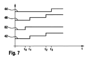
工作機械10との処理プロセスは図5及び図6に基づいて以下の明細書で説明する。さらに工作機械監視装置22の機能形式の説明に対しては図7及び図8が参照される。この図7及び図8では線図において、センサ手段28,30,32,78から送出された電圧として形成された間隔距離パラメータ42,44,46,82が時間tの関数として表されている。なおこれらの相応の間隔距離パラメータ42,44,46,82は図を見やすくする理由からそれぞれy軸上の別々の領域で描写されている。さらに間隔距離パラメータ42,82,46ないし44はそれぞれセンサ手段28,78,32ないし30に対応付けられている。
The processing process with the
ここでは操作者が、木材プレートとして形成された被加工物16の処理を工作機械10を用いて行うものとする。被加工物16を処理面14に載置する前に検出された間隔距離パラメータは同じ間隔距離に相応し、詳細にはセンサ手段28,78,32,30と処理面14との間の間隔に相応している。被加工物16は処理面14上に載置され、そして操作者によって工具18に対する設定方向17に動かされる。時点t0において被加工物16は監視領域74に到達する。図7から明らかなように、間隔距離パラメータ82は跳躍的な変化を伴う移行部を有している。それは監視領域74において被加工物16の厚み分だけの間隔距離の低減に相応している。時点t1では被加工物16が監視領域48と52内に浸入する。その場合間隔距離パラメータ42,46は跳躍的な変化を伴う移行部を有する。さらにここでは被加工物16の設定方向17への移動の際には操作者の手が被加工物16の縁部に存在するものとする(図中の実線で描写された手形参照)。被加工物16のさらなる移動のもとでは時点t2において操作者の手がそれぞれの監視領域48,52のうちの一方に到達する(図6参照)。このことはセンサ手段28,32によって反応される(図7参照)。後続の時点t3では被加工物16が監視領域76に到達する。
Here, it is assumed that the operator uses the
計算ユニット56は、使用状況を論理手法を用いて識別するようにプログラミングされている。1つの使用状況は論理問い合わせの結果として達成される。その際には計算ユニット56が一方では間隔距離パラメータ42,82,46間の差分を監視し、他方では計算ユニット56が全ての間隔距離パラメータの時間経過に反応する。特に間隔距離パラメータ毎に跳躍的変化の伴う複数の移行部が反応する。相応の評価プログラムはメモリユニット84に記憶されている。
The
時点t1とt2の間では間隔距離パラメータ42,82,46かんの全ての差分が値0に等しい。計算ユニット56はこのことを、さらなる手段を講じる必要のない安全な使用状況として解釈する。時点t2において手が監視領域48,52に達すると、間隔距離パラメータ82と間隔距離パラメータ42,46の差分が記録される。このことは論理識別手法においてさらなるステップをトリガし、このさらなるステップでは間隔距離パラメータのそのつどの状態とそれの時間経過が用いられる。計算ユニット56は、特に時点t2では間隔距離パラメータ44がまだその開始状態にあることを確定する。このこともまたさらなる手段を講じる必要のない使用状況として識別される。
Between the instants t 1 and t 2 , all the differences between the
時点t3では、間隔距離パラメータ44の値の変化が記録される。この情報に基づいて計算ユニット56はさらなる間隔距離パラメータの状態を検査する。これらの間隔距離パラメータの値が不変のまま存在し続けるのであるならば、このことは監視領域48,52内の手のさらなる存在に相応し、このことは計算ユニット56によって非クリティカルな使用状況として識別される。
At time t 3 , the change in the value of the
ここで操作者が一方の手を被加工物16の中央領域に載置したものと想定する。このことは図8の線図に基づいて説明する。このような状況は図5及び図6において波線で示された手形88を用いて描写される。被加工物16は先行の実施例と同じように時点t0において監視領域74内に浸入する。時点t4では手が監視領域74内に到達する(図5参照)。このことは間隔距離パラメータ82の跳躍的変化の伴う移行部において表現される。さらに被加工物16が時点t5において監視領域76内に達する。時点t4では下は監視領域74内に到達する。その際には間隔距離42,46と間隔距離82の間で差分が生じ、このことは計算ユニット56によって記録される。さらに計算ユニット56は間隔距離パラメータ82の第2の不連続性ないし断続性が存在することを検出する。このことは計算ユニット56の論理連鎖において次のような使用状況として識別される。すなわち工作機械10の警告モードがスイッチオンされるべき使用状況である。これについては計算ユニット56は警報信号90をアクチュエータユニット81(図4参照)に供給し、これによって一方では信号出力ユニット40による音響的信号の出力が生じ、他方では制御信号92が工作機械駆動ユニット20へ送信される。その際には例えば当該工具18の回転数がより低い値に設定される。
Here, it is assumed that the operator places one hand on the center region of the
操作者がこの警告を無視し、さらに時点t6においてその手が監視領域76に達すると、間隔距離パラメータ44の相応する第2の跳躍的変化の伴う移行部が計算ユニット56によって記録され、これは当該の使用状況を急性の危険状況として識別する。この場合には計算ユニット56は停止信号94をアクチュエータユニット81に対して供給し、これは工作機械駆動ユニット20の安全遮断を引き起こす。さらに別の実施形態では、アクチュエータユニット81が当該の使用状況において安全手段の駆動のために用いられることも考えられる。この安全手段は駆動される工具を工作機械10の作業領域外の安全位置へ調節するものであってもよいし、及び/又は工具18の切断縁部を覆うものであってもよい。
If the operator ignores this warning and the hand reaches the
監視領域74ないし76における間隔距離の低減に基づいて警報信号90と停止信号94をトリガする識別ユニット24により、誤ったネガティブな識別(この場合には使用状況の危険性が過小評価される)が除外される。さらに別の監視領域48,52における間隔距離パラメータ間の比較によって、誤ったポジティブな識別(この場合には使用状況の危険性の過小評価によって警告若しくは安全遮断が引き起こされる)が有利には阻止される。そのような誤ったポジティブな信号の送出を阻止し、快適な使用性を高めるために、前述したような間隔距離センサを有するセンサ系が、特に有利には材料識別機能を備えたさらなるセンサ系と組み合わされる。例えば人体組織の識別のための分光学的手法に基づいて、及び/又は例えばビデオカメラを用いた光学的手法に基づいて、容量性の識別機能及び/又は体熱を関知する赤外線信号を利用した識別機能の付加的な使用などが考えられる。このようなことはさらなるセンサ手段の投入によって達成され得る。またこれらは次のことによって構造的に容易に達成され得る。すなわち少なくともセンサ手段30を付加的に間隔距離検出と材料識別のために用いることによって達成され得る。このセンサ手段30は例えばUWBセンサとして構成されていてもよい。
False negative identification (in this case the risk of usage is underestimated) by the
図1による実施形態の工作機械監視装置22の機能性は、先の説明からもわかるように、監視領域74が省かれている点で異なっている。この監視領域74は警告領域とみなされており、次のような付加的な利点をもたらしている。すなわちクリティカルな使用状況に対して、操作者と工具18の間の物理的な接触が生じる前に反応できる点である。
The functionality of the machine
工作機械監視装置22の機能性の説明のために、使用状況が非ファジイ論理によってプログラミングされた計算ユニット56によって迅速かつ確実に識別できる使用状況の簡単な例を取り上げる。間隔距離パラメータのセットでの検出によって間隔距離パラメータで生じ得るコンフィグレーションの多岐性も得られる。その他にもここでは計算ユニット56が使用状況の効果的な識別のために、使用状況をファジィ論理とニューロン論理に基づいて識別できるように構成されている。ニューロン論理によればさらに有利な工作機械監視装置22自身の学習機能も達成できる。
To illustrate the functionality of the machine
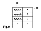
計算ユニット56はさらに使用状況をメモリユニット84内に記憶されているデータバンクを用いて識別できる。このデータバンク96は図9に示されている。このデータバンク96内では間隔距離パラメータ98のセットが符号a1、a2、…b1、b2、…c1、c2で示されており、それぞれ使用状況A,B,Cに対応付けられている。検出されたパラメータセットと記憶されているセットとの比較によって相応する使用状況が識別できるようになる。このようなデータバンク96は例えばコンピュータシミュレーションを用いて形成することができ、そこでは生じ得る使用状況がシミュレートされ、それに続いて順次連続して記憶ユニット84へ記憶される。
The
さらに別の変化実施例として、識別ユニット24をパターン識別のために設けることも考えられる。これに対して計算ユニット56は間隔距離パラメータの絶対値を記録してもよいし、間隔距離パラメータに基づいて求められた間隔を記録してもよい。その際には計算ユニット56は例えば次のようにプログラミング可能である。すなわち計算ユニット56が典型的な手の厚さ(例えば2cm〜5cmの厚み間隔で)を識別するようにプログラミング可能である。
As yet another variant, it is also conceivable to provide an
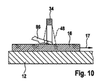
以下では計算ユニット56のさらなる識別モードを図10及び図11に基づいて説明する。ここで手は工具16から次のことによって区別され得る。すなわち計算ユニット56が例えば間隔距離パラメータ42の経過の中で連続的な変化を記録することによって区別される。このような変化は図11中において監視領域48内へ手が浸入している時点t7から検出され、これは被加工物16上で斜めに置かれた手に相応し、それによって生じた検出距離の低減にも相応し、これは間隔距離パラメータ42のパターン経過として計算ユニット56により識別され得る。
In the following, further identification modes of the
これまで丸鋸に基づいて説明してきた本発明による工作機械監視装置22はさらに別の電動工作機械にも適しており、例えば別のタイプの電動鋸、カップ型鋸(Kappsaegen)、留め継ぎ鋸(Gehrungssaegen)や電動芝刈り機などにも適している。
The machine
図12には上方から見た工作機械10の平面図が示されている。この工作機械10は鋸身として、特に円形状の鋸身として形成された工具18を有しており、この工具18は鋸台によって形成される処理面14から、処理面14内に空けられた間隙100を通って被加工物16の載置面に対して突出している。さらに工具18は帯状鋸として形成されていてもよい。規定上の使用条件のもとではこの処理面14は水平方向に配向され、さらに工具18はこの処理面14から垂直方向に突出する(図13参照)。この工具18は工具作動モードにおいて工作機械駆動ユニット20によって回転駆動される。このような工具の駆動時の動きにおいては分離面102が定められており、この分離面102に沿って工具18の切断縁部が被加工物16の切断ないし分離のために回転駆動させられる。図に見られるようなケースにおいては分離面102は垂直方向の平面に相応しており、この面は工具18の重心を含み、工具18の回転軸線に対して垂直方向に配向されている。被加工物の処理の際にはこの分離面102と被加工物の切断線が一致するようにもたらされる。前記処理面14は被加工物処理面104に相応しており、この面に沿って処理すべき被加工物106(図13参照)が規定の処理の際に動かされる。この規定上の処理のもとでは被加工物106は被加工物のシフト方向として構成される被加工物移送方向108において被加工物処理面104に沿ってシフトされる(図13参照)。被加工物移送方向108は分離面102の配向によって定められ、ここでは被加工物処理面104と分離面102に平行している。
FIG. 12 shows a plan view of the
工作機械10は前述してきたように工作機械監視装置22とその識別ユニット24を備えている。この識別ユニット24はセンサユニット110の代替的な実施形態を有している。センサユニット110は6つのセンサ手段112.1〜112.6のセットを含んでいる。センサ手段112はそれぞれ間隔距離センサとして構成されており、このセンサは少なくとも1つの間隔距離パラメータ114の検出のために構成されている(図14参照)。観察されるケースではセンサ手段112がそれぞれ超広帯域レーダーセンサとして構成されている。センサ手段112の構成に対しては代替的に若しくは付加的に様々なセンサ方式が考慮できる。例えば光学的なセンサ系(それらは間隔距離パラメータの検出に対して赤外線ビーム及び/又はレーザービームを用いる)の投入も考えられる。この関係においてはセンサ手段112は三角測量センサとして、あるいはレーザー距離測定装置として構成されていてもよい。その他にも例えば超音波距離測定装置などのような音響的センサとしてのセンサ手段112の構成も考えられる。同様に容量性センサの投入も可能であり、このセンサは間隔距離パラメータをキャパシタンス測定を介して検出する。また別の変化実施例においてこれらのセンサ方式の組み合わせもまた考えられる。
The
センサユニット110はセンサ手段112の2つのグループを有しており、詳細にはセンサ手段112.1,112.3,112.5からなる第一のグループと、センサ手段112.2,112.4,112.6からなる第二のグループを有している。この場合これらのグループは分離面102の両側に配置されている。1つのグループ内ではセンサ手段112が被加工物移送方向108に沿って配設されている。その場合センサ手段は被加工物移送方向108において相前後して配設され、1つの列を形成している。そこでは列方向が被加工物移送方向108に相応する。一方のグループのセンサ手段112、例えばセンサ手段112.2,112.4,112.6には、それぞれ1つの監視領域115.2,115.4,115.6が定められており、この場合これらの監視領域115.2,115.4,115.6も被加工物搬送方向108に沿って一列に配列されている。図12中に示されているセンサ手段の配置構成は例示的なものである。従って一連のセンサ手段112を分離面102の片側にだけ配置するコンフィグレーションも考えられる。さらにまた、一連のセンサ手段112を分離面102に対して相対的にずらして配置するコンフィグレーションも可能である。
The
以下の明細書では、図13〜図16に基づいてセンサユニット110を有する実施例における識別ユニット24の機能性を説明する。図4による識別ユニット24を有する工作機械10の内部回路の描写は相応の使用状況を明らかにし、この場合センサユニット72がセンサユニット110に置き換えられている。図13では工作機械10の側面図が示されている。センサ手段112は図13における描写からも明らかなように、処理面14の下方に配設されている。この図面では被加工物106の規定の処理が示されており、この場合は被加工物106が被加工物移送方向108において操作者により、被加工物処理面104に沿って、床に対して固定的に構成されている工作機械10に対して相対的にシフトされる。センサ手段112.2,112.4,112.6によって検出された間隔距離パラメータ114.2,114.4.114.6の経過は、時間tの関数として図14に示されている。そこではセンサ手段112.2,112.4,112.6の相応する監視領域115.2,115.4,115.6内への被加工物106の漸次の介入が跳躍的変化の伴う移行に基づいて識別できる。時点t=0における間隔距離パラメータ114の初期値は、相応するセンサ手段112.2,112.4,112.6の覆われていない状態に相応している。
In the following specification, the functionality of the
センサユニット110を有する実施形態における識別ユニット24は次のことのために設けられている。すなわち、被加工物106の予測不能な動き、すなわち図示の例では処理面14からの被加工物106の突発的な離脱が識別できるように設けられている。このことは図15に概略的に示されている。この使用状況においては、時点t1において被加工物106が傾斜(Vetkanten)に基づいて次のような応力を被る。すなわち上方に向けての垂直方向成分と被加工物移送方向108に抗する成分とを有している応力である。それに従って被加工物106は被加工物処理面104から上方に向けて垂直方向101に上昇し、いわゆる"キックバック"、すなわち被加工物移送方向108に抗して操作者の方に向かって動く。間隔距離パラメータ114の相応の経過は図16に示されている。使用状況の識別のために、間隔距離パラメータ114の相応する時間変化並びに検出された間隔距離パラメータ114間の比較が評価される。
The
被加工物106の工作機械10に対する予測不能な動き若しくはコントロール不能な動きは、間隔距離パラメータ114.2及び114.4の瞬時の値の比較から識別することが可能である。その場合は特に計算ユニット56によって時点t1において間隔距離パラメータ114.4に変化が起きたことが記録される。この変化はセンサ手段112.4から被加工物106までの間隔距離の変化を意味している。その場合時点t1における間隔距離パラメータ114.2の値はセンサ手段112.2のさらなる覆われた状態を意味している。この識別は識別ユニット24に識別信号をトリガさせ、この信号に基づいて保護手段が導入される。
Unpredictable or uncontrollable movement of the
その他に被加工物106の予測不能な動きは間隔距離パラメータ114の変化値の評価によっても識別できる。この変化値が所定の閾値を上回ると、計算ユニット56は被加工物処理面104に対する被加工物106の突発的な動きを、操作者によって目論まれそれに応じて操作される動きと区別する。この場合の変化値は計算ユニット56を用いて段階付けられ、その中では瞬時の変化値が種々のリスクレベル、例えば"通常の変化"若しくは"突発的な変化"などに対応付けられる。種々のリスクレベルには様々な安全手段が割り当てられる。図示の例では時点t1における間隔距離パラメータ114の変化値が"突発的変化"に割当てられ、それによって識別ユニット24の識別信号が安全手段の開始のためにトリガされる。
In addition, the unpredictable movement of the
さらに識別ユニット24を用いて図15に示されている被加工物処理面104に対する被加工物106の動きがその方向性で特徴付けられてもよい。その場合には計算ユニット56によって次のことが記録される。すなわち、時点t1における2つの間隔距離パラメータ114.2,114.4の同時変化の生じたことが記録される。このことは被加工物処理面104からの被加工物106の引き上げ運動を意味している。
Furthermore, the movement of the
さらに識別ユニット24を用いて被加工物移送方向108に抗する被加工物106のキックバック成分が識別され得る。このことは既に時点t1以降の間隔距離パラメータ114.2,114.4が異なる値を有していることを識別し、これは図15に示されているような被加工物処理面104に対する被加工物106の傾斜状態を意味している。この状態ではセンサ手段112.4と被加工物106との間の間隔距離がセンサ手段112.2と被加工物106との間の間隔距離よりも大きい。その他にも計算ユニット56により、間隔距離パラメータ114.2と114.4の変化値の比較によってキックバック運動が評価され得る。計算ユニット56は特に、間隔距離パラメータ114.4が間隔距離パラメータ114.2よりも大きい変化値を有していることを記録する。このことは次のようなことを示唆している。すなわちセンサ手段112.4の監視領域115.4における被加工物被加工物処理面104と被加工物106との間の間隔距離が、センサ手段112.2の監視領域115.2における間隔距離よりも早く上昇したことを示唆している。その結果から、操作者方向へのキックバックを伴う被加工物106の横滑りが生じたことが識別され、このことは図15中の曲がった矢印を用いて概略的に表されている。さらにこのキックバックは次のようなことからも識別され得る。すなわち時点t2>t1に対して間隔距離パラメータ114.4がその初期値を有していることからも識別され得る。それに対して間隔距離パラメータ114.2はセンサ手段112.2がさらに覆われている状態に相応する。
Furthermore, the
さらに工作機器10に対する被加工物106の予期しない運動の識別のために間隔距離パラメータ114の監視においてさらなる組み合わせも考えられる。前述したように説明した識別はデータバンク96のデータの引き寄せによって行われる。識別ユニット24の識別信号に基づいて様々な保護手段が講じられ得る。例えば前述したようにアクチュエータユニット81を用いて工作機械駆動ユニット20の安全遮断がトリガされる。さらにここではアクチュエータユニット81が機械的安全手段を起動操作することも考えられる。この安全手段では例えば工具18が被加工物処理面104の下方に沈められたり、及び/又は工具18の切断縁部のカバーが実施される。
Further combinations are also conceivable in the monitoring of the distance distance parameter 114 for identification of unexpected movement of the
さらなる変化実施例によれば、工作機械10が分離溝として形成された保護装置を有し、この保護装置が被加工物移送方向108において工具18後方に配設される。この保護装置は間隔距離パラメータの検出のために被加工物処理面104上方に配設される少なくとも1つのさらなるセンサ手段を支持するための支持ユニットとして形成されてもよい。
According to a further variant embodiment, the
図17にはハンディ丸鋸として構成された工作機械116の側面図が示されている。この丸鋸は工作機械構成部117を有しており、この工作機械構成部117が工具118として円形状の鋸身の形態で構成されている。この工具118は作動モードにおいて図には詳細には示されていない工作機械駆動ユニットによって回転駆動されている。この回転運動により前述したような分離面が定められる。図17中は被加工物120が、図には詳細には示されていない構成要素を用いて床に対して固定された位置に緊締される。被加工物120の規定の処理においては当該工作機械116が被加工物120の表面を移動し、その際工作機械116に向いた表面が工作機械処理面122を定めている。特にこの工作機械116は規定上は、被加工物120に対して相対的な工作機械移送方向124にシフトされ、これは分離面と工作機械処理面122に対して平行している。
FIG. 17 shows a side view of a
工作機械116は工作機械監視装置22を備えている。この工作機械監視装置22は識別ユニット24を有しており、該識別ユニット24は、センサ手段112を備えたセンサユニット110を含んでいる。既に図12において描写したコンフィグレーションのように、前記センサユニット110はセンサ手段112の2つのグループに分割され、それらは分離面の両側に配設されている。さらにセンサ手段112は1つのグループ内で工作機械移送方向124に沿って一列に配置されている。
The
図18には工作機械処理面122に対して操作者が予測できない動きを生じている工作機械116が描写されている。この場合は被加工物120において工具118の傾斜が生じ、それによって工作機械処理面122に対する工作機械116の引き上げ運動が起きている。この工作機械116の被加工物120に対する相対的な動きはさらに1つの成分、すなわち工作機械移送方向124に対して対抗的に配向された成分、すなわち被加工物120が工作機械移送方向124に対してキックバックを生じる成分が含まれている。
FIG. 18 depicts a
図18に示されているセンサ手段112.1,112.3ないし112.5に対応付けられている間隔距離パラメータ114.1,114.3,114.5の経過は時間tの関数として図19に示されている。時点t=0から傾斜の時点t1まで、図14に基づいて説明した前記センサ手段112.1,112.3,112.5が漸次被加工物120によって覆われている。時点t1における間隔距離パラメータ114の同時性の変化が(これは工作機械116の被加工物処理面122からの上昇移動を意味している)計算ユニット56によって記録される。さらにこの計算ユニット56は間隔距離パラメータ114の瞬時の変化値の比較を行う。その結果からセンサ手段112.5の被加工物120までの間隔距離がセンサ手段112.1の被加工物120までの間隔距離よりも早く上昇していることが識別され得る。このことは工具118が工作機械移送方向124に反する少なくとも1つの成分によって操作者への方向に動いていることを示唆している。このことは計算ユニット56により、危険な状況として識別される。それにより安全手段、特に工具118の駆動の停止が開始される。前記図16の説明はさらに相応する適用例にも当てはまる。さらなる安全手段として機械的な保護装置のトリガ、例えば工具118の切断縁部のカバーのための保護フードも考えられる。ここでは次のような変化実施例も可能である。すなわち工作機械116の安定化のための安定化手段、例えば釣り合いおもり要素を突発的な上昇運動の補償のために操作する実施例も可能である。
The passage of the distance distance parameters 114.1, 114.3, 114.5 associated with the sensor means 112.1, 112.3 to 112.5 shown in FIG. 18 is a function of the time t. Is shown in From the time t = 0 to the time t 1 of the inclination, the sensor means 112.1, 112.3, 112.5 described with reference to FIG. The change in simultaneity of the spacing distance parameter 114 at time t 1 is recorded by the calculation unit 56 (which means an upward movement from the
識別ユニット24の信頼性を高めるために、識別ユニット24が付加的なセンサを備えていてもよく、そのような付加的センサとは、センサユニット110に対して冗長的なセンサ系である。特に有利には識別ユニット24は、センサユニット110に対して加速度センサを備えさせてもらう。
In order to increase the reliability of the
図20には工作機械116の代替的実施例が示されている。この機械116は、工具118の実施形態により長手方向の鋸身として構成されている。図16による実施形態に関連して、同じ機能を有する構成部分には、同じ参照符号が付されている。工具118は被加工物の駆動中に被加工物処理面122に対して垂直な昇降運動のために駆動される。この動きは分離面を定め、該分離面は工具118の重心を含み、被加工物処理面122と鋸身の長手側面に対して平行に配向されている。工作機械116は既に前述したように規定上は工作機械移送方向124で操作者によってシフトされる。センサユニット110はセンサ手段112.1,112.2の対を有しており、これらは分離面の両側に配設されている。工具118の傾斜の際、若しくは被加工物120下方に存在する障害物への衝突の際には、工作機械116は被加工物処理面122に対して上昇移動する。これはセンサ手段112によって検出された間隔距離パラメータ114の識別ユニット24を用いた評価によって行われる。但しこれについては説明の繰り返しとなるのでここでの詳細な説明は省く。安全手段としては既に前述したように工具118の駆動部の安全遮断が実行され得る。これは例えば工作機械駆動ユニットのスイッチオフによって行われてもよいし、若しくは工作機械駆動ユニットからの工具118の取り外しによって行われてもよい。
FIG. 20 shows an alternative embodiment of the
分離面の両側へのセンサ手段112の配置は、被加工物の処理が操作者自身による工作機械116の取扱いによって行われるような工作機械116の実施形態においては特に有利となる。これにより識別ユニット24によって、例えば被加工物の切断部分が分離して床に落下する使用状況や工作機械116が被加工物処理面122から離れるような使用状況間で区別がなされるようになる。
The arrangement of the sensor means 112 on both sides of the separation surface is particularly advantageous in embodiments of the
Claims (25)
前記識別ユニット(24)が少なくとも1つの間隔距離パラメータ(42,44,46,82,98;114)に基づいて使用状況を識別するように構成されていることを特徴とする工作機械監視装置。 In a machine tool monitoring device provided with an identification unit (24) for use situation identification in a machine tool (10; 116),
Machine tool monitoring device, characterized in that the identification unit (24) is arranged to identify the usage status based on at least one distance parameter (42, 44, 46, 82, 98; 114).
適用状況の識別のために、少なくとも1つの間隔距離パラメータ(42,44,46,82,98;114)が検出されることを特徴とする方法。 In a method for identifying application status in an application process of a machine tool (10; 116),
A method, characterized in that at least one distance parameter (42, 44, 46, 82, 98; 114) is detected for application status identification.
Applications Claiming Priority (3)
| Application Number | Priority Date | Filing Date | Title |
|---|---|---|---|
| DE102006041755 | 2006-09-04 | ||
| DE102007041097A DE102007041097A1 (en) | 2006-09-04 | 2007-08-30 | Machine tool monitoring device |
| PCT/EP2007/059246 WO2008028911A1 (en) | 2006-09-04 | 2007-09-04 | Machine tool monitoring device |
Publications (1)
| Publication Number | Publication Date |
|---|---|
| JP2010503096A true JP2010503096A (en) | 2010-01-28 |
Family
ID=38719719
Family Applications (1)
| Application Number | Title | Priority Date | Filing Date |
|---|---|---|---|
| JP2009527129A Pending JP2010503096A (en) | 2006-09-04 | 2007-09-04 | Machine tool monitoring device |
Country Status (7)
| Country | Link |
|---|---|
| US (1) | US8615320B2 (en) |
| EP (1) | EP2076357B1 (en) |
| JP (1) | JP2010503096A (en) |
| AT (1) | ATE522320T1 (en) |
| DE (1) | DE102007041097A1 (en) |
| RU (1) | RU2459138C2 (en) |
| WO (1) | WO2008028911A1 (en) |
Cited By (5)
| Publication number | Priority date | Publication date | Assignee | Title |
|---|---|---|---|---|
| JP2011524263A (en) * | 2008-06-18 | 2011-09-01 | ローベルト ボツシユ ゲゼルシヤフト ミツト ベシユレンクテル ハフツング | Machine tool monitoring device |
| JP2013071194A (en) * | 2011-09-27 | 2013-04-22 | Hitachi Koki Co Ltd | Cutting machine, and emergency stop method of motor |
| JP2014501179A (en) * | 2010-12-16 | 2014-01-20 | ローベルト ボツシユ ゲゼルシヤフト ミツト ベシユレンクテル ハフツング | Operation method of safety device for operating device, safety device for operating device, and operating device |
| JP2020529928A (en) * | 2017-07-24 | 2020-10-15 | フェストール・ゲゼルシャフト・ミト・ベシュレンクテル・ハフツング | Power tools and kickbacks of power tools-a method for recognizing the phenomenon |
| JP2020535026A (en) * | 2017-09-29 | 2020-12-03 | フェスツール ゲーエムベーハー | Portable machine tool |
Families Citing this family (25)
| Publication number | Priority date | Publication date | Assignee | Title |
|---|---|---|---|---|
| US6922153B2 (en) * | 2003-05-13 | 2005-07-26 | Credo Technology Corporation | Safety detection and protection system for power tools |
| DE102007044804A1 (en) * | 2007-09-20 | 2009-04-09 | Robert Bosch Gmbh | Machine tool safety device |
| DE102008001727A1 (en) * | 2008-05-13 | 2009-11-19 | Robert Bosch Gmbh | machine tool |
| DE102010054855B4 (en) * | 2010-12-17 | 2015-06-11 | Deckel Maho Pfronten Gmbh | Machine tool, in particular program-controlled milling and drilling machine |
| US10222781B2 (en) | 2010-12-17 | 2019-03-05 | Deckel Maho Pfronten Gmbh | Apparatus for monitoring and providing visual representations of the operating conditions of machine tool parameters |
| CN102407461B (en) * | 2011-08-03 | 2013-04-24 | 杭州电子科技大学 | Real-time detecting device for full-distance linear velocity of metal band sawing machine |
| US10161566B2 (en) * | 2013-11-18 | 2018-12-25 | Robert Bosch Tool Corporation | Power tool with capacitive injury mitigation system |
| RU2548973C1 (en) * | 2013-11-22 | 2015-04-20 | Федеральное государственное автономное образовательное учреждение высшего профессионального образования "Санкт-Петербургский государственный университет аэрокосмического приборостроения" | Apparatus for simulating gravitational traction engine when combating asteroid hazard |
| US10330258B2 (en) * | 2013-12-24 | 2019-06-25 | Robert Bosch Tool Corporation | Power tool with ultrasonic sensor for sensing contact between an implement and an object |
| DE102014210612A1 (en) * | 2014-06-04 | 2015-12-17 | Holzma Plattenaufteiltechnik Gmbh | Method of operating a plate processing plant, and plate processing plant |
| US9810524B2 (en) | 2015-12-15 | 2017-11-07 | Sears Brands, L.L.C. | Power tool with optical measurement device |
| AU2017262385B2 (en) * | 2016-05-12 | 2019-06-20 | Kando Innovation Limited | Enhanced safety attachment for cutting machine |
| CN106863360A (en) * | 2017-03-31 | 2017-06-20 | 上汽通用五菱汽车股份有限公司 | A kind of bent axle manipulator workpiece type recognition methods |
| US10906110B2 (en) | 2017-04-28 | 2021-02-02 | Transform Sr Brands Llc | Power tool with integrated measurement device and associated methods |
| EP3488984A1 (en) * | 2017-11-24 | 2019-05-29 | SCM Group S.p.A. | Machine for working workpieces, made of wood and the like, provided with a system for detecting the presence of an operator, and operation method thereof |
| DE102018216933A1 (en) | 2018-10-02 | 2020-04-02 | Festool Gmbh | Power tool |
| DE102018127518A1 (en) * | 2018-11-05 | 2020-05-07 | Advanced Realtime Tracking Gmbh | Device and method for processing at least one work area with a processing tool |
| CN111553179B (en) * | 2019-02-12 | 2023-05-05 | 阿里巴巴集团控股有限公司 | Clothing quality inspection state, action state determining method and device and electronic equipment |
| IT201900004211A1 (en) * | 2019-03-22 | 2020-09-22 | Comacchio S R L | SAFETY SYSTEM FOR WORKING PARTS OF DRILLING OR PROCESSING MACHINES IN GENERAL, AND METHOD OF OPERATION OF SAID SAFETY SYSTEM |
| TWI751434B (en) * | 2019-08-22 | 2022-01-01 | 邱智煇 | Machine tool |
| DE102020207520A1 (en) * | 2019-09-02 | 2021-03-04 | Robert Bosch Gesellschaft mit beschränkter Haftung | Machine tool device |
| US11648616B2 (en) * | 2019-12-20 | 2023-05-16 | Milwaukee Electric Tool Corporation | Reciprocating saw |
| DE202021100243U1 (en) | 2021-01-19 | 2022-04-20 | Altendorf Gmbh | Format circular saw with safety device to avoid cut injuries |
| CN114433658A (en) * | 2022-02-15 | 2022-05-06 | 苏州三姆森光电科技有限公司 | Flatness shaping machine tool and shaping method |
| CN114833611B (en) * | 2022-07-04 | 2022-09-30 | 广东原点智能技术有限公司 | Fixture capable of identifying workpiece model and numerical control machine tool |
Citations (2)
| Publication number | Priority date | Publication date | Assignee | Title |
|---|---|---|---|---|
| JP2004160822A (en) * | 2002-11-12 | 2004-06-10 | Makita Corp | Power tool |
| JP2006511770A (en) * | 2002-12-23 | 2006-04-06 | ローベルト ボツシユ ゲゼルシヤフト ミツト ベシユレンクテル ハフツング | Device for contact protection and method for protecting a movable member before contact |
Family Cites Families (12)
| Publication number | Priority date | Publication date | Assignee | Title |
|---|---|---|---|---|
| SU1208396A1 (en) * | 1984-06-04 | 1986-01-30 | Андроповский авиационный технологический институт | Protective device of working zone |
| US5212645A (en) * | 1990-07-19 | 1993-05-18 | General Electric Company | Flexible real-time, multi-tasking architecture for tool condition monitoring |
| JP3100406B2 (en) * | 1991-03-06 | 2000-10-16 | ジヤトコ・トランステクノロジー株式会社 | Machine tool failure prediction device |
| US6041271A (en) * | 1991-10-10 | 2000-03-21 | Finn-Power International, Inc. | Apparatus to determine the operational effectiveness of a machine tool and method therefor |
| CA2095398C (en) * | 1993-05-03 | 2001-06-12 | Kalyan Ghosh | System for detecting human presence in hazardous situations |
| JP3025421B2 (en) * | 1995-06-14 | 2000-03-27 | 三菱電機株式会社 | Abnormality detection device for control system |
| EP1061487A1 (en) * | 1999-06-17 | 2000-12-20 | Istituto Trentino Di Cultura | A method and device for automatically controlling a region in space |
| US6604013B1 (en) * | 2000-10-11 | 2003-08-05 | Ford Motor Company | Tool failure detection utilizing frequency derived, pre-characterization templates |
| CA2448479C (en) | 2002-11-12 | 2009-05-05 | Makita Corporation | Power tools |
| JP2005088248A (en) | 2003-09-12 | 2005-04-07 | Makita Corp | Power tool |
| JP4359573B2 (en) * | 2005-03-31 | 2009-11-04 | オークマ株式会社 | Machine tool thermal displacement compensation method |
| US20090199610A1 (en) * | 2005-04-06 | 2009-08-13 | Kikuchi Seisakusho Co., Ltd. | Actuator, parallel link mechanism using the same, and long material bending device |
-
2007
- 2007-08-30 DE DE102007041097A patent/DE102007041097A1/en not_active Withdrawn
- 2007-09-04 US US12/439,781 patent/US8615320B2/en active Active
- 2007-09-04 EP EP07803210A patent/EP2076357B1/en active Active
- 2007-09-04 WO PCT/EP2007/059246 patent/WO2008028911A1/en active Application Filing
- 2007-09-04 JP JP2009527129A patent/JP2010503096A/en active Pending
- 2007-09-04 AT AT07803210T patent/ATE522320T1/en active
- 2007-09-04 RU RU2009112163/02A patent/RU2459138C2/en not_active IP Right Cessation
Patent Citations (2)
| Publication number | Priority date | Publication date | Assignee | Title |
|---|---|---|---|---|
| JP2004160822A (en) * | 2002-11-12 | 2004-06-10 | Makita Corp | Power tool |
| JP2006511770A (en) * | 2002-12-23 | 2006-04-06 | ローベルト ボツシユ ゲゼルシヤフト ミツト ベシユレンクテル ハフツング | Device for contact protection and method for protecting a movable member before contact |
Cited By (11)
| Publication number | Priority date | Publication date | Assignee | Title |
|---|---|---|---|---|
| JP2011524263A (en) * | 2008-06-18 | 2011-09-01 | ローベルト ボツシユ ゲゼルシヤフト ミツト ベシユレンクテル ハフツング | Machine tool monitoring device |
| JP2014501179A (en) * | 2010-12-16 | 2014-01-20 | ローベルト ボツシユ ゲゼルシヤフト ミツト ベシユレンクテル ハフツング | Operation method of safety device for operating device, safety device for operating device, and operating device |
| US9296106B2 (en) | 2010-12-16 | 2016-03-29 | Robert Bosch Gmbh | Method for operating a safety device for a handling device, safety device for a handling device, and handling device |
| JP2013071194A (en) * | 2011-09-27 | 2013-04-22 | Hitachi Koki Co Ltd | Cutting machine, and emergency stop method of motor |
| JP2020529928A (en) * | 2017-07-24 | 2020-10-15 | フェストール・ゲゼルシャフト・ミト・ベシュレンクテル・ハフツング | Power tools and kickbacks of power tools-a method for recognizing the phenomenon |
| JP7050897B2 (en) | 2017-07-24 | 2022-04-08 | フェストール・ゲゼルシャフト・ミト・ベシュレンクテル・ハフツング | Power tools and methods for recognizing the kickback phenomenon of power tools |
| US11491564B2 (en) | 2017-07-24 | 2022-11-08 | Festool Gmbh | Power tool, system, and method |
| US11701723B2 (en) | 2017-07-24 | 2023-07-18 | Festool Gmbh | Power tool, system, and method |
| JP2020535026A (en) * | 2017-09-29 | 2020-12-03 | フェスツール ゲーエムベーハー | Portable machine tool |
| US11426808B2 (en) | 2017-09-29 | 2022-08-30 | Festool Gmbh | Mobile machine tool |
| JP7354095B2 (en) | 2017-09-29 | 2023-10-02 | フェスツール ゲーエムベーハー | portable machine tools |
Also Published As
| Publication number | Publication date |
|---|---|
| RU2459138C2 (en) | 2012-08-20 |
| EP2076357B1 (en) | 2011-08-31 |
| US20100152882A1 (en) | 2010-06-17 |
| DE102007041097A1 (en) | 2008-03-06 |
| RU2009112163A (en) | 2010-10-20 |
| EP2076357A1 (en) | 2009-07-08 |
| US8615320B2 (en) | 2013-12-24 |
| WO2008028911A1 (en) | 2008-03-13 |
| ATE522320T1 (en) | 2011-09-15 |
Similar Documents
| Publication | Publication Date | Title |
|---|---|---|
| JP2010503096A (en) | Machine tool monitoring device | |
| US9489730B2 (en) | Method and device for safeguarding a hazardous working area of an automated machine | |
| US8051759B2 (en) | Motion detecting system for use in a safety system for power equipment | |
| JP4031042B2 (en) | Optical device for mounting on moving parts | |
| EP3548792B1 (en) | Monitoring device for monitoring a boundary section of a safety zone | |
| EP1442834B1 (en) | Machine safety protection system | |
| US20040181951A1 (en) | Chain saw safety system | |
| AU2017210492B2 (en) | Power tool with capacitive injury mitigation system | |
| US20190001504A1 (en) | Method For Detecting A Collision Of A Robot Arm With An Object, And A Robot With A Robot Arm | |
| JP2003222295A (en) | Method and device for controlling safety-related function of machine | |
| JPH09168980A (en) | Method and apparatus for cutting operation of portable tool machine | |
| CN110869178A (en) | Hand-held circular saw | |
| CN101512211B (en) | Machine tool monitoring device | |
| US20190234559A1 (en) | Method and system to monitor and shut down saw | |
| CN101511531A (en) | Machine tool monitoring device | |
| EP3473387A1 (en) | Robot supervision system | |
| WO2019232142A1 (en) | Method and system to control, automate, monitor, and shut down a deli slicer | |
| CN110270717A (en) | Electric cutting tool | |
| WO2018024889A1 (en) | Blade guard having a safety feature | |
| CN117697180A (en) | Laser cutting system and method capable of preventing personal injury | |
| KR20200015352A (en) | Apparatus and method for monitoring objects, particularly tools of tooling devices, and/or mechanically scanning objects, in particular tools or workpieces and a computer program for driving such a device and/or performing such a method |
Legal Events
| Date | Code | Title | Description |
|---|---|---|---|
| RD04 | Notification of resignation of power of attorney |
Free format text: JAPANESE INTERMEDIATE CODE: A7424 Effective date: 20101228 Free format text: JAPANESE INTERMEDIATE CODE: A7424 Effective date: 20101227 |
|
| A131 | Notification of reasons for refusal |
Free format text: JAPANESE INTERMEDIATE CODE: A131 Effective date: 20110902 |
|
| A521 | Request for written amendment filed |
Free format text: JAPANESE INTERMEDIATE CODE: A523 Effective date: 20111201 |
|
| A131 | Notification of reasons for refusal |
Free format text: JAPANESE INTERMEDIATE CODE: A131 Effective date: 20120419 |
|
| A601 | Written request for extension of time |
Free format text: JAPANESE INTERMEDIATE CODE: A601 Effective date: 20120718 |
|
| A602 | Written permission of extension of time |
Free format text: JAPANESE INTERMEDIATE CODE: A602 Effective date: 20120725 |
|
| A521 | Request for written amendment filed |
Free format text: JAPANESE INTERMEDIATE CODE: A523 Effective date: 20121015 |
|
| A02 | Decision of refusal |
Free format text: JAPANESE INTERMEDIATE CODE: A02 Effective date: 20130306 |