EP3548792B1 - Monitoring device for monitoring a boundary section of a safety zone - Google Patents
Monitoring device for monitoring a boundary section of a safety zone Download PDFInfo
- Publication number
- EP3548792B1 EP3548792B1 EP19702303.9A EP19702303A EP3548792B1 EP 3548792 B1 EP3548792 B1 EP 3548792B1 EP 19702303 A EP19702303 A EP 19702303A EP 3548792 B1 EP3548792 B1 EP 3548792B1
- Authority
- EP
- European Patent Office
- Prior art keywords
- radar
- boundary section
- light curtain
- monitoring
- safety zone
- Prior art date
- Legal status (The legal status is an assumption and is not a legal conclusion. Google has not performed a legal analysis and makes no representation as to the accuracy of the status listed.)
- Active
Links
- 238000012806 monitoring device Methods 0.000 title claims description 62
- 238000012544 monitoring process Methods 0.000 title claims description 18
- 238000011156 evaluation Methods 0.000 claims description 50
- 238000001514 detection method Methods 0.000 claims description 45
- 230000001681 protective effect Effects 0.000 claims description 20
- 239000000463 material Substances 0.000 claims description 18
- 238000000034 method Methods 0.000 claims description 9
- 230000006870 function Effects 0.000 description 9
- 239000011111 cardboard Substances 0.000 description 7
- 238000004519 manufacturing process Methods 0.000 description 4
- 239000004033 plastic Substances 0.000 description 3
- 230000005236 sound signal Effects 0.000 description 3
- 239000002023 wood Substances 0.000 description 3
- 239000002184 metal Substances 0.000 description 2
- 241000282412 Homo Species 0.000 description 1
- 241001465754 Metazoa Species 0.000 description 1
- 230000004888 barrier function Effects 0.000 description 1
- 230000001419 dependent effect Effects 0.000 description 1
- 238000012986 modification Methods 0.000 description 1
- 230000004048 modification Effects 0.000 description 1
- 238000012856 packing Methods 0.000 description 1
- 239000000123 paper Substances 0.000 description 1
- 230000008569 process Effects 0.000 description 1
- 230000000007 visual effect Effects 0.000 description 1
Images


Classifications
-
- F—MECHANICAL ENGINEERING; LIGHTING; HEATING; WEAPONS; BLASTING
- F16—ENGINEERING ELEMENTS AND UNITS; GENERAL MEASURES FOR PRODUCING AND MAINTAINING EFFECTIVE FUNCTIONING OF MACHINES OR INSTALLATIONS; THERMAL INSULATION IN GENERAL
- F16P—SAFETY DEVICES IN GENERAL; SAFETY DEVICES FOR PRESSES
- F16P3/00—Safety devices acting in conjunction with the control or operation of a machine; Control arrangements requiring the simultaneous use of two or more parts of the body
- F16P3/12—Safety devices acting in conjunction with the control or operation of a machine; Control arrangements requiring the simultaneous use of two or more parts of the body with means, e.g. feelers, which in case of the presence of a body part of a person in or near the danger zone influence the control or operation of the machine
- F16P3/14—Safety devices acting in conjunction with the control or operation of a machine; Control arrangements requiring the simultaneous use of two or more parts of the body with means, e.g. feelers, which in case of the presence of a body part of a person in or near the danger zone influence the control or operation of the machine the means being photocells or other devices sensitive without mechanical contact
- F16P3/144—Safety devices acting in conjunction with the control or operation of a machine; Control arrangements requiring the simultaneous use of two or more parts of the body with means, e.g. feelers, which in case of the presence of a body part of a person in or near the danger zone influence the control or operation of the machine the means being photocells or other devices sensitive without mechanical contact using light grids
-
- B—PERFORMING OPERATIONS; TRANSPORTING
- B25—HAND TOOLS; PORTABLE POWER-DRIVEN TOOLS; MANIPULATORS
- B25J—MANIPULATORS; CHAMBERS PROVIDED WITH MANIPULATION DEVICES
- B25J19/00—Accessories fitted to manipulators, e.g. for monitoring, for viewing; Safety devices combined with or specially adapted for use in connection with manipulators
- B25J19/02—Sensing devices
- B25J19/021—Optical sensing devices
-
- F—MECHANICAL ENGINEERING; LIGHTING; HEATING; WEAPONS; BLASTING
- F16—ENGINEERING ELEMENTS AND UNITS; GENERAL MEASURES FOR PRODUCING AND MAINTAINING EFFECTIVE FUNCTIONING OF MACHINES OR INSTALLATIONS; THERMAL INSULATION IN GENERAL
- F16P—SAFETY DEVICES IN GENERAL; SAFETY DEVICES FOR PRESSES
- F16P3/00—Safety devices acting in conjunction with the control or operation of a machine; Control arrangements requiring the simultaneous use of two or more parts of the body
- F16P3/12—Safety devices acting in conjunction with the control or operation of a machine; Control arrangements requiring the simultaneous use of two or more parts of the body with means, e.g. feelers, which in case of the presence of a body part of a person in or near the danger zone influence the control or operation of the machine
- F16P3/14—Safety devices acting in conjunction with the control or operation of a machine; Control arrangements requiring the simultaneous use of two or more parts of the body with means, e.g. feelers, which in case of the presence of a body part of a person in or near the danger zone influence the control or operation of the machine the means being photocells or other devices sensitive without mechanical contact
- F16P3/147—Safety devices acting in conjunction with the control or operation of a machine; Control arrangements requiring the simultaneous use of two or more parts of the body with means, e.g. feelers, which in case of the presence of a body part of a person in or near the danger zone influence the control or operation of the machine the means being photocells or other devices sensitive without mechanical contact using electro-magnetic technology, e.g. tags or radar
-
- G—PHYSICS
- G01—MEASURING; TESTING
- G01P—MEASURING LINEAR OR ANGULAR SPEED, ACCELERATION, DECELERATION, OR SHOCK; INDICATING PRESENCE, ABSENCE, OR DIRECTION, OF MOVEMENT
- G01P3/00—Measuring linear or angular speed; Measuring differences of linear or angular speeds
- G01P3/64—Devices characterised by the determination of the time taken to traverse a fixed distance
- G01P3/68—Devices characterised by the determination of the time taken to traverse a fixed distance using optical means, i.e. using infrared, visible, or ultraviolet light
Definitions
- the present invention relates to a monitoring device for monitoring a boundary section of a safety zone and to a method for monitoring such a boundary section.
- Light curtain devices can be used to detect the presence of an object along a boundary section of a safety zone. When an object is detected, a warning signal may be emitted.
- a light curtain device can be arranged at a boundary of a dangerous zone of a manufacturing site to detect that a human is passing the boundary of the dangerous zone. It can be desired to obtain further information about the boundary section of the safety zone to thereby improve the monitoring of said boundary section.
- the document DE 10 2012 007 520 B3 discloses combinations of different sensors that are chosen such as to fulfill given detection purposes. As an example, it is suggested to monitor a zone around a forklift using two laser scanners and a radar. However, in DE 10 2012 007 520 B3 , the various sensors are used to monitor entire zones and a monitoring of a boundary section of a safety zone is not addressed.
- Document DE 42 33 810 C2 discloses a monitoring device for a work machine which comprises a light curtain for detecting an object or a person entering a work area of the work machine.
- the monitoring device further includes a rotating scanning device for detecting a presence of an object or a person within the work area.
- document DE 20 2004 020 863 U1 discloses a monitoring apparatus for monitoring an area comprising a dangerous machine located in a dangerous area.
- the monitoring apparatus comprises a light curtain and a protection device which is implemented as a laser scanner.
- a monitoring device for monitoring a boundary section of a safety zone for detecting an object at least partially entering or leaving the safety zone through the boundary section.
- the monitoring device comprises:
- the safety zone can be a three dimensional or two-dimensional region. It may be at least partially delimited by the boundary section.
- the safety zone is a dangerous zone, for example a dangerous zone of a factory arrangement comprising a dangerous factory device.
- the safety zone can be a virtual zone, which does not have any physical boundaries.
- the boundary section may be a two-dimensional area or a one-dimensional line.
- the boundary section is a plane delimiting the safety zone.
- the boundary section can be the boundary between the inside of the safety zone and the outside of the safety zone. In particular, the boundary section delimits a dangerous zone from a non-dangerous zone.
- the boundary section may also be a virtual area which is not defined by any physical boundaries.
- the object can be any type of visible item.
- it can be a manufactured object, a human, a vehicle or the like.
- the light curtain device may detect whether any object is touching the boundary section or not. It can be considered that an object is touching the boundary section if any part thereof is in contact with the boundary section. In particular, an object that crosses the boundary section touches the boundary section. For example, the object has to touch the boundary section to at least partially enter or leave the safety zone.
- the light curtain device can be arranged along the boundary section, in particular at an edge of the boundary section.
- the light curtain device can comprise a light emitting element for emitting light beams, for example in a pulsed manner at predetermined frequency, as well as a light receiving element for receiving only light at the predetermined frequency.
- a light emitting element for emitting light beams, for example in a pulsed manner at predetermined frequency
- a light receiving element for receiving only light at the predetermined frequency.
- the light emitting element can emit the light along the boundary section, in particular such that the light is emitted along a grid that coincides with the boundary section.
- the light emitting element is arranged on one side of the boundary section and the light receiving element is arranged on the other side of the boundary section.
- the light curtain device may determine the light curtain device signal, which for example indicates whether an object touches the boundary section or not.
- the radar device can be a device that uses radar waves for detecting the distance between the radar device and an object, and/or an angle between a reference plane of the radar device and the object.
- a 3D position of the object can be determined by combining the information about the distance and angle of the object.
- the position of the object can be expressed relative to the boundary section.
- the movement direction of the object relative to the boundary section can be determined by analysing subsequent positions of the object.
- the radar device is configured to perform a three-dimensional monitoring of a zone monitored by the radar device.
- the radar device may further be used to detect the material property of the object.
- the material property of the object can for example be whether the object is made of wood, plastic, metal, paper, cardboard or if it is a human or an animal. This material property may be part of the radar device signal.
- the radar device can comprise a radar emitter for emitting the radar waves and a radar receiver for receiving the radar waves.
- the radar receiver receives radar waves that are reflected by the object and are indicative of the position, movement direction and/or material property of the object.
- the size of the radar wave received by the radar receiver can vary depending on the permittivity of the object.
- An analysis of the radar waves received by the radar receiver may allow to determine the permittivity of the object.
- the material out of which the object is made can be determined from its permittivity.
- the radar device signal can be determined by the radar device and may indicate the position of the object, the movement direction of the object relative to the boundary section and/or the material property of the object.
- the movement direction relative to the boundary section for example indicates whether the objects moves towards the boundary section or away from the boundary section.
- the radar waves emitted by the radar device may have frequencies ranging between 18 GHz and 40 GHz, in particular between 20 GHz and 30 GHz.
- the evaluation device can receive the radar device signal from the radar device and/or the light curtain device signal from the light curtain device. The evaluation device may evaluate this or these receives signal(s) and determine the evaluation result based thereon.
- the light curtain device and the radar device are used in combination to monitor the boundary section of the safety zone.
- the radar device may allow to monitor not only the boundary section itself but also its surroundings. Thereby, objects approaching the boundary section may be detected and it can be possible to predict critical events occurring at the boundary section such as crossings of the boundary section.
- the monitoring of the safety zone can thereby be improved. In particular, it can be prevented that an object enters the safety zone more reliably.
- the monitoring device further comprises a protection device for emitting a warning signal and/or performing a predetermined protective measure based on the evaluation result.
- the evaluation device can send the evaluation result to the protection device.
- the protection device may take a decision regarding a protective measure to be taken in view of the evaluation result. For example, if the evaluation result indicates an immediate danger, the protection device can perform an emergency protective measure. This can be the case when the result indicates that an object is entering the safety zone. In this case, the evaluation device may, as a protective measure, turn off and/or slow down any dangerous facilities (such as factory devices) located in the safety zone to avoid damaging the entering object.
- the evaluation device can also, as another protective measure, provide a physical barrier to prevent the object from attaining the dangerous facilities of the safety zone.
- the protection device can take different types of predetermined protective measures.
- the protection device determines the predetermined protective measure in accordance with the evaluation result.
- the protection device can also choose to take no actions if the evaluation result is not critical, in particular if no object is detected at or close to the boundary section.
- the emission of the warning signal can be an example of a predetermined protective measure.
- the warning signal can be a light signal or a sound signal.
- the protection device allows to protect the boundary section, the safety zone and/or the object by taking appropriate protective measures depending on the evaluation result.
- the monitoring device further comprises a muting device for temporarily deactivating the protection device and/or the light curtain device as a function of the evaluation result.
- the process of temporarily deactivating the protection device and/or the light curtain device performed by the muting device can be called "muting".
- the muting function may be performed when the monitoring device recognizes that no critical event is occurring or about to occur.
- the muting can prevent the protection device from unnecessarily performing the predetermined protective measure.
- the muting can be activated when the monitoring device recognises, based on the evaluation result, that the object passing the boundary section is leaving the safety zone, that the object is a non-critical object and/or when the object moves at a predetermined speed.
- muting can be performed when the material property of the object as detected by the radar device indicates that the object is made of plastic or wood, while it may be deactivated when the material property of the object as detected by the radar device indicates that the object is a human, in particular when a human enters the safety zone. Taking into account the material property of the object may thus improve the monitoring of the boundary section.
- the muting device performs the muting function when the object is detected in a muting zone.
- Said muting zone can be within the safety zone.
- the muting zone touches the boundary section.
- the muting device does not perform the muting function when the object is detected in an alarm zone.
- Said alarm zone can be outside the safety zone.
- the alarm zone touches the boundary section.
- the evaluation result indicates whether the object is inside or outside the safety zone, the movement direction of the object relative to the boundary section as detected by the radar device and/or whether the object is touching the boundary section.
- the evaluation result indicates whether the object is inside or outside the safety zone based on the position of the object determined by the radar device.
- an object that is inside the safety zone can be a product that is being manufactured while an object outside the safety zone can be a human, in particular a technician, in the case that the safety zone is a dangerous zone of a factory arrangement or manufacturing site.
- the evaluation result can also indicate whether the object is located within the muting zone or the alarm zone.
- the movement direction of the object relative to the boundary section for example indicates whether the object is moving towards or away from the boundary section. In particular, it can indicate whether the object is about to leave or to enter the safety zone through the boundary section or whether the object is entering or leaving the safety zone through the boundary section.
- the indication that the object is touching the boundary may be derived from the light curtain device signal from the light curtain device.
- the radar device has a detection region, wherein the radar device and the light curtain device are arranged such that the detection region at least partially overlaps with the boundary section.
- the detection region of the radar device is the region that is reached by the radar waves and in which the radar device can detect the position of an object and/or a movement direction of the object relative to the boundary section.
- the detection region may have an ellipsoidal shape.
- the boundary section is covered by the detection region.
- the boundary section is entirely within the detection region.
- the detection region has an elongated shape with a detection axis, and the radar device and the light curtain device are arranged such that the detection axis runs parallel to the boundary section.
- the radar and the light curtain device are arranged together on one side of the boundary section.
- a main direction along which the radar device emits the radar signal which can correspond to the detection axis, can be parallel to a main direction along which the light curtain device emits the light signal.
- the detection region may be symmetric around the detection axis.
- the detection region has an elongated shape with a detection axis, and the radar device and the light curtain device are arranged such that the detection axis runs perpendicular to the boundary section.
- the light curtain device and the radar device are not arranged at the same geometric position with respect to the safety zone.
- the radar device is arranged within or outside the safety zone.
- the light curtain device comprises a plurality of light emitting elements arranged on or at a first support element and a plurality of light receiving elements arranged on or at a second support element, the boundary section being between the support elements.
- the light emitting elements emit light along the boundary section.
- the radar device comprises a radar sender and a radar receiver, the radar sender and the radar receiver being arranged at or on at least one of the first and/or second support element.
- the radar sender and/or the radar receiver can be arranged on the same support element as the light emitting elements and/or the light receiving elements.
- the radar sender and radar receiver may be positioned on the same support element.
- the radar device comprises a radar sender and a radar receiver, the radar sender and the radar receiver being arranged at a predetermined distance from the first and the second support element.
- the safety zone is situated between the radar device and the light curtain device.
- the radar device and the light curtain device are arranged such that the safety zone is located therebetween.
- the factory arrangement comprises:
- the factory device is a manufacturing device, a conveyor belt or a packing device. It can comprise dangerous elements such as saws, drills, laser cutters and the like.
- the factory device can be used to manufacture objects such as metal, plastic or wood objects and/or to pack them in boxes, for example in cardboard boxes.
- a human enters in contact with the dangerous elements of the factory device as the human may injure himself.
- the safety of the human may be provided by the monitoring device already described above. In particular, when a box leaves the safety zone, there is no danger and muting is performed. Alternatively, when a human is about to enter the safety zone, the monitoring device may recognize the danger and not perform the muting.
- a method for monitoring a boundary section of a safety zone comprises:
- Fig. 1 shows a monitoring device 1 according to a first embodiment.
- the monitoring device 1 comprises a light curtain device 4, a radar device 5 and an evaluation device 7 which are connected to one another through cables 8.
- the functionality of the monitoring device 1 will be described in view of Fig. 2 , which shows a factory arrangement 10 according to a first embodiment.
- the factory arrangement 10 comprises the monitoring device 1 of Fig. 1 .
- the factory arrangement 10 is viewed from above.
- the monitoring device 1 is used to monitor a boundary section 3 of a safety zone 2.
- the safety zone 2 corresponds to a dangerous zone comprising a dangerous factory device 26.
- the factory device 26 is a laser cutter used to cut objects to be manufactured. It is desired that humans, for example technicians, stay outside the safety zone 2 to avoid getting injured by the laser cutter 26.
- the safety zone 2 is a virtual cuboid that is delimited by the boundary section 3 on one side.
- the boundary section 3 is a plane. In Fig. 2 , the boundary section 3 is represented as a dashed line while the remaining boundaries of the safety zone 2 are represented by dashed-and-dotted lines.
- the light curtain device 4 comprises a light emitting element 4a and a light receiving element 4b arranged with the boundary section 3 therebetween.
- the light emitting element 4a emits light as a light beam 9 along the boundary section 3.
- the light receiving element 4b receives the light emitted by the light emitting element 4a.
- the radar device 5 is used contemporaneously to the light curtain device 4.
- the radar device 5 monitors a detection region 15 using radar waves.
- the detection region has a conical shape with a detection axis 28 along the boundary section 3.
- the radar device 5 can detect its position and a movement direction of the object 6 relative to the boundary section 3.
- the radar device 5 determines that the object is in the dangerous zone 2 and that it is moving towards a non-dangerous zone 27 outside the dangerous zone 2.
- the movement direction of the object 6 is indicated by the direction arrow 18.
- the object 6 is an object that is being manufactured by the laser cutter 26 but has unintentionally been dropped.
- a detection signal of the light curtain device 4 also called light curtain device signal (LDS)
- a detection signal of the radar device 5 also called radar device signal (RDS)
- RDS radar device signal
- the evaluation unit 7 evaluates the two signals LDS, RDS and determines and emits an evaluation result based thereon.
- the evaluation result indicates whether the object 6 is inside or outside the safety zone 2, whether the object 6 moves towards the boundary section 3 or away from it, and whether the object touches the boundary section 3 or not. In the example shown in Fig. 2 , the evaluation result indicates that the object 6 is in the safety zone 2 moving towards the boundary section 3 but not touching the boundary section 3 (yet).
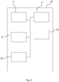
- Fig. 3 shows a monitoring device 20 according to a second embodiment.
- the monitoring device 20 according to the second embodiment differs from the monitoring device 1 according to the first embodiment in that it further comprises a protection device 21 and a muting device 22, the functions of which will be described in the following with reference to Fig. 4 to 7B .
- Fig. 4 shows a factory arrangement 25 according to a second embodiment.
- the factory arrangement 25 comprises the monitoring device 20 according to the second embodiment.
- the factory arrangement 25 according to the second embodiment differs from the factory arrangement 10 according to the first embodiment in that the factory device 11 is a conveyor belt for bringing objects 14 from a first part 12 to a second part 13 of the factory arrangement 25.
- the objects 14 are boxes.
- the conveyor belt 11 is within the safety zone or dangerous zone 2.
- the monitoring device 20 comprises a first support element 16 and a second support element 17.
- the first support element 16 comprises five identical light emitting elements 4a arranged at regular intervals and each emitting light as a light beam 9 along the boundary section 3.
- the second support element 17 comprises five identical light receiving elements 4b arranged at regular intervals for detecting the light emitted from the respective light emitting elements 4a.
- the first support element 16 comprises four radar devices 5, each comprising a radar sender 5a and a radar receiver 5b.
- the radar sender 5a and the radar receiver 5b are located very close to one another.
- the radar senders 5a send the radar waves along the detection zone 15, which here has an ellipsoidal shape.
- the radar receivers 5b receive the emitted radar waves coming back. The received signal depends on whether an object 14 is located within the detection zone 15, on the position of such an object 14 and/or on its movement direction.
- the monitoring device 20 allows to distinguish between objects located in an alarm zone 23 and objects located in a muting zone 24, as will be described below.
- the alarm zone 23 corresponds to the half of the detection zone 15 which is located on the outside of the safety zone 2 while the muting zone 24 corresponds to the half of the detection zone 15 which is located within the safety zone 2.
- FIG. 6A, 6B , 7A and 7B it will be described how the monitoring device 20 according to the second embodiment is used to monitor the boundary section 3.
- the conveyor belt 11 is not shown for clarity reasons, but it is understood that the factory arrangement 25 is the same in Fig. 6A, 6B , 7A and 7B as in Fig. 4 .
- an object 19 moves towards the safety zone 2 along the direction 18.
- the object 19 is a human.
- the position of the human 19 and his movement direction is detected by the radar device 5 provided in the first support element 16 because the human 19 is within the detection region 15.
- the evaluation device 7 determines, as an evaluation result, that the human 19 is in the alarm zone 23 of the detection region 15 (i.e. in the bottom half of the detection region 15 in Fig. 6A ) and that it is moving towards the boundary section 3.
- the protection device 21 When the evaluation result indicates the presence of an object in the alarm zone, the protection device 21 performs a predetermined protective measure. Indeed, there is a risk that the human 19 crosses the boundary section 13 and enters the dangerous safety zone 2.
- the protection device 21 here emits an alarm, in particular a sound signal, as a protective measure to indicate the danger. When hearing the sound signal, it is expected that the human 19 stops and turns around before entering the dangerous zone 2.
- the human 19 does not stop and turn around despite the warning alarm (see Fig. 6B ). In this case, the human 19 can go as far as to touch the boundary section 3.
- the light curtain device 4 sends a light curtain device signal LDS to the evaluation device 7 indicating that an object 19 is touching the boundary section 3.
- the radar device 5 sends a radar device signal RDS indicating that the object 19 moves towards the dangerous zone 2.
- the evaluation device 7 combines the received information to obtain an evaluation result indicating that the object 19 is touching the boundary section 3 and that the object 19 moves towards the dangerous zone 2.
- the protection device 21 recognizes an immediate danger and turns off the dangerous factory device 11 to avoid the human 19 getting injured.
- the monitoring device 20 takes appropriate protective measures to avoid the human 19 getting injured.
- the factory device 11 is only turned off when it is necessary.
- Fig. 7A and 7B show an example in which a box 14 is leaving the dangerous area 2. It can happen that a box 14 falls from the conveyor belt 11, thereby causing it to cross the boundary section 3 and to leave the dangerous zone 2.
- the radar device 5 detects that an object 14 is located in the muting zone 24 of the detection region 15 and that it moves towards boundary section 3.
- the light curtain device 4 does not detect the presence of the object 14 touching the boundary section 3.
- the evaluation result indicates that the object 14 is located in the muting zone 24 and approaching the boundary section 3.
- This evaluation result causes the muting device 22 of the monitoring device 20 to perform a muting function. This means that the muting device 22 temporarily deactivates the light curtain device 4. Indeed, there is no danger when the box 14 falls out of the safety zone 2 and it is hence unnecessary to turn off the conveyor belt 11.
- the muting is for example deactivated when the monitoring device 20 detects that the object 14 has completely passed the boundary section 3 and/or is moving away from the boundary section 3.
- Fig. 8A shows a factory arrangement 35 according to a third embodiment.
- the factory arrangement 35 differs from the factory arrangement 25 according to the second embodiment in that it comprises a monitoring device 30 according to a third embodiment instead of the monitoring device 20 according to the second embodiment.
- the monitoring device 30 according to the third embodiment differs from the monitoring device 20 according to the second embodiment in that the radar device 5 is not part of a first support element 31 but is rather arranged away therefrom. In particular, the radar device 5 is neither part of the first support element 31 nor of a second support element 32
- the radar device 5 is arranged such that the safety zone 2 is located between the radar device 5 and the boundary section 3 defined by the light curtain device 2.
- the detection axis 28 of the radar device 5 is perpendicular to the boundary section 3.
- the monitoring device 30 can also detect the material out of which a detected object is made. This material detection is performed by the radar device 5. In the monitoring device 30, the evaluation result is determined as a function of the material property of the detected object.
- a cardboard box 14 is approaching the boundary section 3 from outside the safety zone 2. Although the cardboard box 14 is within the alarm zone 23 of the detection region 15, there is no danger because the cardboard box 14 is not a human. Thus, when the monitoring device 30 detects that the box 14 is made of cardboard, no alarm is emitted by the protective device 21. In addition, when the detected object 14 is made of cardboard or of another non-human material, the muting device 22 temporarily deactivates the light curtain device 4 such that the conveyor belt 11 is not turned off when said object touches the boundary section 3.
- a human 19 is approaching the boundary section 3 from the outside of the safety zone 2.
- the radar device 5 detects that the object is a human 19.
- the evaluation result indicates that a human 19 is in the alarm zone 23, thereby indicating that there is a risk of injuring the human 19.
- the protection device 21 emits a warning signal and if the human 19 touches the boundary section 3, the conveyor belt 11 is further turned off, as described in view of Fig. 6A and 6B .
- Fig. 9 shows a method for monitoring a boundary section 3 of a safety zone 2.
- the monitoring device 1, 20, 30 is provided.
- the light curtain device 4 is operated to detect if an object 6, 14, 19 touches the boundary section 3.
- at least one radar device 5 is contemporaneously operated for detecting a position of the object 6, 14, 19 and/or a movement direction of the object 6, 14, 19 relative to the boundary section 3.
- an evaluation result is emitted based on a signal from the radar device 5 and optionally based on a signal from the light curtain device 4.
- the protective measures performed by the protection device 21 can be different and can include the emission of a visual warning signal.
- the shapes and sizes of the detection region, safety zone, alarm zone and/or muting zone can vary. Different protective measures can be performed by the protection device 21 depending on the material of the detected object, the position of the object and/or its movement direction.
- the monitoring device 1, 20, 30 can also be used to detect the presence, position and movement direction of several objects at the time and to perform appropriate protective measures.
Description
- The present invention relates to a monitoring device for monitoring a boundary section of a safety zone and to a method for monitoring such a boundary section.
- Light curtain devices can be used to detect the presence of an object along a boundary section of a safety zone. When an object is detected, a warning signal may be emitted. For example, a light curtain device can be arranged at a boundary of a dangerous zone of a manufacturing site to detect that a human is passing the boundary of the dangerous zone. It can be desired to obtain further information about the boundary section of the safety zone to thereby improve the monitoring of said boundary section.
- The document
DE 10 2012 007 520 B3 discloses combinations of different sensors that are chosen such as to fulfill given detection purposes. As an example, it is suggested to monitor a zone around a forklift using two laser scanners and a radar. However, inDE 10 2012 007 520 B3 - Document
DE 42 33 810 C2 discloses a monitoring device for a work machine which comprises a light curtain for detecting an object or a person entering a work area of the work machine. The monitoring device further includes a rotating scanning device for detecting a presence of an object or a person within the work area. - Further,
document DE 20 2004 020 863 U1 discloses a monitoring apparatus for monitoring an area comprising a dangerous machine located in a dangerous area. The monitoring apparatus comprises a light curtain and a protection device which is implemented as a laser scanner. - It is one object of the present invention to provide an improved monitoring of a boundary section of a safety zone.
- Accordingly, a monitoring device for monitoring a boundary section of a safety zone for detecting an object at least partially entering or leaving the safety zone through the boundary section is provided. The monitoring device comprises:
- a light curtain device for detecting an object touching the boundary section;
- at least one radar device for detecting a movement direction of the object relative to the boundary section and/or a material property of the object; and
- an evaluation device for emitting an evaluation result based on a radar device signal from the radar device and optionally based on a light curtain device signal from the light curtain device.
- The safety zone can be a three dimensional or two-dimensional region. It may be at least partially delimited by the boundary section. In embodiments, the safety zone is a dangerous zone, for example a dangerous zone of a factory arrangement comprising a dangerous factory device. The safety zone can be a virtual zone, which does not have any physical boundaries.
- The boundary section may be a two-dimensional area or a one-dimensional line. For example, the boundary section is a plane delimiting the safety zone. The boundary section can be the boundary between the inside of the safety zone and the outside of the safety zone. In particular, the boundary section delimits a dangerous zone from a non-dangerous zone. The boundary section may also be a virtual area which is not defined by any physical boundaries.
- The object can be any type of visible item. For example, it can be a manufactured object, a human, a vehicle or the like.
- The light curtain device may detect whether any object is touching the boundary section or not. It can be considered that an object is touching the boundary section if any part thereof is in contact with the boundary section. In particular, an object that crosses the boundary section touches the boundary section. For example, the object has to touch the boundary section to at least partially enter or leave the safety zone. The light curtain device can be arranged along the boundary section, in particular at an edge of the boundary section.
- To detect the presence of an object touching the boundary section, the light curtain device can comprise a light emitting element for emitting light beams, for example in a pulsed manner at predetermined frequency, as well as a light receiving element for receiving only light at the predetermined frequency. When the power of the light emitted by the light emitting element changes, for example due to the presence of an object touching the boundary section, the light curtain device recognizes the presence of the object touching the boundary section.
- The light emitting element can emit the light along the boundary section, in particular such that the light is emitted along a grid that coincides with the boundary section. In embodiments, the light emitting element is arranged on one side of the boundary section and the light receiving element is arranged on the other side of the boundary section. The light curtain device may determine the light curtain device signal, which for example indicates whether an object touches the boundary section or not.
- The radar device can be a device that uses radar waves for detecting the distance between the radar device and an object, and/or an angle between a reference plane of the radar device and the object. In particular, a 3D position of the object can be determined by combining the information about the distance and angle of the object. The position of the object can be expressed relative to the boundary section. The movement direction of the object relative to the boundary section can be determined by analysing subsequent positions of the object. In particular, the radar device is configured to perform a three-dimensional monitoring of a zone monitored by the radar device.
- The radar device may further be used to detect the material property of the object. The material property of the object can for example be whether the object is made of wood, plastic, metal, paper, cardboard or if it is a human or an animal. This material property may be part of the radar device signal.
- The radar device can comprise a radar emitter for emitting the radar waves and a radar receiver for receiving the radar waves. In particular, the radar receiver receives radar waves that are reflected by the object and are indicative of the position, movement direction and/or material property of the object.
- For example, the size of the radar wave received by the radar receiver can vary depending on the permittivity of the object. An analysis of the radar waves received by the radar receiver may allow to determine the permittivity of the object. In particular, the material out of which the object is made can be determined from its permittivity.
- The radar device signal can be determined by the radar device and may indicate the position of the object, the movement direction of the object relative to the boundary section and/or the material property of the object. The movement direction relative to the boundary section for example indicates whether the objects moves towards the boundary section or away from the boundary section.
- The radar waves emitted by the radar device may have frequencies ranging between 18 GHz and 40 GHz, in particular between 20 GHz and 30 GHz.
- The evaluation device can receive the radar device signal from the radar device and/or the light curtain device signal from the light curtain device. The evaluation device may evaluate this or these receives signal(s) and determine the evaluation result based thereon.
- In particular, the light curtain device and the radar device are used in combination to monitor the boundary section of the safety zone. The radar device may allow to monitor not only the boundary section itself but also its surroundings. Thereby, objects approaching the boundary section may be detected and it can be possible to predict critical events occurring at the boundary section such as crossings of the boundary section. The monitoring of the safety zone can thereby be improved. In particular, it can be prevented that an object enters the safety zone more reliably.
- According to an embodiment, the monitoring device further comprises a protection device for emitting a warning signal and/or performing a predetermined protective measure based on the evaluation result.
- The evaluation device can send the evaluation result to the protection device. The protection device may take a decision regarding a protective measure to be taken in view of the evaluation result. For example, if the evaluation result indicates an immediate danger, the protection device can perform an emergency protective measure. This can be the case when the result indicates that an object is entering the safety zone. In this case, the evaluation device may, as a protective measure, turn off and/or slow down any dangerous facilities (such as factory devices) located in the safety zone to avoid damaging the entering object. The evaluation device can also, as another protective measure, provide a physical barrier to prevent the object from attaining the dangerous facilities of the safety zone.
- Depending on the evaluation result, the protection device can take different types of predetermined protective measures. In particular, the protection device determines the predetermined protective measure in accordance with the evaluation result. The protection device can also choose to take no actions if the evaluation result is not critical, in particular if no object is detected at or close to the boundary section.
- The emission of the warning signal can be an example of a predetermined protective measure. The warning signal can be a light signal or a sound signal.
- The protection device allows to protect the boundary section, the safety zone and/or the object by taking appropriate protective measures depending on the evaluation result.
- According to a further embodiment, the monitoring device further comprises a muting device for temporarily deactivating the protection device and/or the light curtain device as a function of the evaluation result.
- The process of temporarily deactivating the protection device and/or the light curtain device performed by the muting device can be called "muting". The muting function may be performed when the monitoring device recognizes that no critical event is occurring or about to occur. The muting can prevent the protection device from unnecessarily performing the predetermined protective measure. For example, the muting can be activated when the monitoring device recognises, based on the evaluation result, that the object passing the boundary section is leaving the safety zone, that the object is a non-critical object and/or when the object moves at a predetermined speed. Further, muting can be performed when the material property of the object as detected by the radar device indicates that the object is made of plastic or wood, while it may be deactivated when the material property of the object as detected by the radar device indicates that the object is a human, in particular when a human enters the safety zone. Taking into account the material property of the object may thus improve the monitoring of the boundary section.
- In embodiments, the muting device performs the muting function when the object is detected in a muting zone. Said muting zone can be within the safety zone. In particular, the muting zone touches the boundary section.
- In embodiment, the muting device does not perform the muting function when the object is detected in an alarm zone. Said alarm zone can be outside the safety zone. In particular, the alarm zone touches the boundary section.
- According to a further embodiment, the evaluation result indicates whether the object is inside or outside the safety zone, the movement direction of the object relative to the boundary section as detected by the radar device and/or whether the object is touching the boundary section.
- In particular, the evaluation result indicates whether the object is inside or outside the safety zone based on the position of the object determined by the radar device. For example, an object that is inside the safety zone can be a product that is being manufactured while an object outside the safety zone can be a human, in particular a technician, in the case that the safety zone is a dangerous zone of a factory arrangement or manufacturing site. The evaluation result can also indicate whether the object is located within the muting zone or the alarm zone.
- The movement direction of the object relative to the boundary section for example indicates whether the object is moving towards or away from the boundary section. In particular, it can indicate whether the object is about to leave or to enter the safety zone through the boundary section or whether the object is entering or leaving the safety zone through the boundary section.
- The indication that the object is touching the boundary may be derived from the light curtain device signal from the light curtain device.
- According to a further embodiment, the radar device has a detection region, wherein the radar device and the light curtain device are arranged such that the detection region at least partially overlaps with the boundary section.
- In particular, the detection region of the radar device is the region that is reached by the radar waves and in which the radar device can detect the position of an object and/or a movement direction of the object relative to the boundary section. The detection region may have an ellipsoidal shape.
- According to a further embodiment, the boundary section is covered by the detection region. In particular, the boundary section is entirely within the detection region.
- According to a further embodiment, the detection region has an elongated shape with a detection axis, and the radar device and the light curtain device are arranged such that the detection axis runs parallel to the boundary section.
- In particular, the radar and the light curtain device are arranged together on one side of the boundary section. A main direction along which the radar device emits the radar signal, which can correspond to the detection axis, can be parallel to a main direction along which the light curtain device emits the light signal. The detection region may be symmetric around the detection axis.
- According to a further embodiment, the detection region has an elongated shape with a detection axis, and the radar device and the light curtain device are arranged such that the detection axis runs perpendicular to the boundary section.
- In particular, the light curtain device and the radar device are not arranged at the same geometric position with respect to the safety zone. In embodiments, the radar device is arranged within or outside the safety zone.
- According to a further embodiment, the light curtain device comprises a plurality of light emitting elements arranged on or at a first support element and a plurality of light receiving elements arranged on or at a second support element, the boundary section being between the support elements. In particular, the light emitting elements emit light along the boundary section.
- According to a further embodiment, the radar device comprises a radar sender and a radar receiver, the radar sender and the radar receiver being arranged at or on at least one of the first and/or second support element.
- In particular, the radar sender and/or the radar receiver can be arranged on the same support element as the light emitting elements and/or the light receiving elements. The radar sender and radar receiver may be positioned on the same support element.
- According to a further embodiment, the radar device comprises a radar sender and a radar receiver, the radar sender and the radar receiver being arranged at a predetermined distance from the first and the second support element.
- According to a further embodiment, the safety zone is situated between the radar device and the light curtain device. In particular, the radar device and the light curtain device are arranged such that the safety zone is located therebetween.
- According to a second aspect, a factory arrangement is provided. The factory arrangement comprises:
- a safety zone delimited by at least one boundary section, wherein, in the safety zone, at least one factory device is arranged and implemented to perform a predetermined function; and
- a monitoring device according to the first aspect or according to an embodiment of the first aspect, implemented to detect if an object at least partially enters or leaves the safety zone through the boundary section.
- For example, the factory device is a manufacturing device, a conveyor belt or a packing device. It can comprise dangerous elements such as saws, drills, laser cutters and the like. The factory device can be used to manufacture objects such as metal, plastic or wood objects and/or to pack them in boxes, for example in cardboard boxes. In particular, it should be avoided that a human enters in contact with the dangerous elements of the factory device as the human may injure himself. The safety of the human may be provided by the monitoring device already described above. In particular, when a box leaves the safety zone, there is no danger and muting is performed. Alternatively, when a human is about to enter the safety zone, the monitoring device may recognize the danger and not perform the muting.
- According to a third aspect, a method for monitoring a boundary section of a safety zone is provided. The method comprises:
- operating a light curtain device to detect if an object touches the boundary section; and
- contemporaneously operating at least one radar device for detecting a movement direction of the object relative to the boundary section and/or a material property of the object; and
- emitting an evaluation result based on a radar device signal from the radar device and optionally based on a light curtain device signal from the light curtain device.
- The embodiments and features described with reference to the monitoring device according to the first aspect or according to an embodiment of the first aspect apply mutatis mutandis to the factory arrangement according to the second aspect and to the method according to the third aspect.
- Further possible implementations or alternative solutions of the invention also encompass combinations - that are not explicitly mentioned herein - of features described above or below with regard to the embodiments. The person skilled in the art may also add individual or isolated aspects and features to the most basic form of the invention.
- Further embodiments, features and advantages of the present invention will become apparent from the subsequent description and dependent claims, taken in conjunction with the accompanying drawings, in which:
- Fig. 1
- shows a monitoring device according to a first embodiment;
- Fig. 2
- shows a factory arrangement according to a first embodiment;
- Fig. 3
- shows a monitoring device according to a second embodiment;
- Fig. 4
- shows a factory arrangement according to a second embodiment;
- Fig. 5
- shows a detailed view of the monitoring device according to the second embodiment;
- Fig. 6A
- shows a view of a first example of an object detected by the monitoring device according to the second embodiment;
- Fig. 6B
- shows another view of the first example of the object detected by the monitoring device according to the second embodiment
- Fig. 7A
- shows a view of a second example of an object detected by the monitoring device according to the second embodiment;
- Fig. 7B
- shows another view of the second example of the object detected by the monitoring device according to the second embodiment
- Fig. 8A
- shows a factory arrangement according to a third embodiment detecting a first object;
- Fig. 8B
- shows a factory arrangement according to a third embodiment detecting a second object; and
- Fig. 9
- shows a method for monitoring a boundary section of a safety zone.
- In the Figures, like reference numerals designate like or functionally equivalent elements, unless otherwise indicated.
-
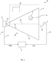
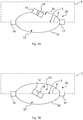
Fig. 1 shows amonitoring device 1 according to a first embodiment. Themonitoring device 1 comprises alight curtain device 4, aradar device 5 and anevaluation device 7 which are connected to one another throughcables 8. The functionality of themonitoring device 1 will be described in view ofFig. 2 , which shows afactory arrangement 10 according to a first embodiment. - The
factory arrangement 10 comprises themonitoring device 1 ofFig. 1 . InFig. 2 , thefactory arrangement 10 is viewed from above. Themonitoring device 1 is used to monitor aboundary section 3 of asafety zone 2. Thesafety zone 2 corresponds to a dangerous zone comprising adangerous factory device 26. In the present example, thefactory device 26 is a laser cutter used to cut objects to be manufactured. It is desired that humans, for example technicians, stay outside thesafety zone 2 to avoid getting injured by thelaser cutter 26. Thesafety zone 2 is a virtual cuboid that is delimited by theboundary section 3 on one side. Theboundary section 3 is a plane. InFig. 2 , theboundary section 3 is represented as a dashed line while the remaining boundaries of thesafety zone 2 are represented by dashed-and-dotted lines. - The
light curtain device 4 comprises alight emitting element 4a and alight receiving element 4b arranged with theboundary section 3 therebetween. Thelight emitting element 4a emits light as alight beam 9 along theboundary section 3. Thelight receiving element 4b receives the light emitted by thelight emitting element 4a. Depending on the frequency of the light received by thelight receiving element 4b, it can be determined whether anobject 6 touches thelight beam 9 and hence theboundary section 3. InFig. 2 , theobject 6 is not touching theboundary section 3. - The
radar device 5 is used contemporaneously to thelight curtain device 4. Theradar device 5 monitors adetection region 15 using radar waves. The detection region has a conical shape with adetection axis 28 along theboundary section 3. When theobject 6 is within thedetection region 15, theradar device 5 can detect its position and a movement direction of theobject 6 relative to theboundary section 3. For theobject 6 ofFig. 2 , theradar device 5 determines that the object is in thedangerous zone 2 and that it is moving towards anon-dangerous zone 27 outside thedangerous zone 2. InFig. 2 , the movement direction of theobject 6 is indicated by thedirection arrow 18. - The
object 6 is an object that is being manufactured by thelaser cutter 26 but has unintentionally been dropped. - A detection signal of the
light curtain device 4, also called light curtain device signal (LDS), is sent to theevaluation unit 7 by thelight curtain device 4 for evaluation. A detection signal of theradar device 5, also called radar device signal (RDS), is sent to theevaluation unit 7 by theradar device 4 for evaluation. Theevaluation unit 7 evaluates the two signals LDS, RDS and determines and emits an evaluation result based thereon. The evaluation result indicates whether theobject 6 is inside or outside thesafety zone 2, whether theobject 6 moves towards theboundary section 3 or away from it, and whether the object touches theboundary section 3 or not. In the example shown inFig. 2 , the evaluation result indicates that theobject 6 is in thesafety zone 2 moving towards theboundary section 3 but not touching the boundary section 3 (yet). -
Fig. 3 shows amonitoring device 20 according to a second embodiment. Themonitoring device 20 according to the second embodiment differs from themonitoring device 1 according to the first embodiment in that it further comprises aprotection device 21 and amuting device 22, the functions of which will be described in the following with reference toFig. 4 to 7B . -
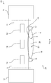
Fig. 4 shows afactory arrangement 25 according to a second embodiment. Thefactory arrangement 25 comprises themonitoring device 20 according to the second embodiment. Thefactory arrangement 25 according to the second embodiment differs from thefactory arrangement 10 according to the first embodiment in that thefactory device 11 is a conveyor belt for bringingobjects 14 from afirst part 12 to asecond part 13 of thefactory arrangement 25. In the second embodiment, theobjects 14 are boxes. Theconveyor belt 11 is within the safety zone ordangerous zone 2. - As shown in
Fig. 4 and5 , themonitoring device 20 comprises afirst support element 16 and asecond support element 17. Thefirst support element 16 comprises five identicallight emitting elements 4a arranged at regular intervals and each emitting light as alight beam 9 along theboundary section 3. Correspondingly, thesecond support element 17 comprises five identicallight receiving elements 4b arranged at regular intervals for detecting the light emitted from the respectivelight emitting elements 4a. - Additionally, the
first support element 16 comprises fourradar devices 5, each comprising aradar sender 5a and aradar receiver 5b. Theradar sender 5a and theradar receiver 5b are located very close to one another. Theradar senders 5a send the radar waves along thedetection zone 15, which here has an ellipsoidal shape. Theradar receivers 5b receive the emitted radar waves coming back. The received signal depends on whether anobject 14 is located within thedetection zone 15, on the position of such anobject 14 and/or on its movement direction. - The
monitoring device 20 allows to distinguish between objects located in analarm zone 23 and objects located in a mutingzone 24, as will be described below. Thealarm zone 23 corresponds to the half of thedetection zone 15 which is located on the outside of thesafety zone 2 while the mutingzone 24 corresponds to the half of thedetection zone 15 which is located within thesafety zone 2. - Referring to
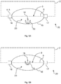
Fig. 6A, 6B ,7A and 7B , it will be described how themonitoring device 20 according to the second embodiment is used to monitor theboundary section 3. In theFig. 6A, 6B ,7A and 7B , theconveyor belt 11 is not shown for clarity reasons, but it is understood that thefactory arrangement 25 is the same inFig. 6A, 6B ,7A and 7B as inFig. 4 . - In
Fig. 6A , anobject 19 moves towards thesafety zone 2 along thedirection 18. Theobject 19 is a human. The position of the human 19 and his movement direction is detected by theradar device 5 provided in thefirst support element 16 because the human 19 is within thedetection region 15. In the present case, theevaluation device 7 determines, as an evaluation result, that the human 19 is in thealarm zone 23 of the detection region 15 (i.e. in the bottom half of thedetection region 15 inFig. 6A ) and that it is moving towards theboundary section 3. - When the evaluation result indicates the presence of an object in the alarm zone, the
protection device 21 performs a predetermined protective measure. Indeed, there is a risk that the human 19 crosses theboundary section 13 and enters thedangerous safety zone 2. Theprotection device 21 here emits an alarm, in particular a sound signal, as a protective measure to indicate the danger. When hearing the sound signal, it is expected that the human 19 stops and turns around before entering thedangerous zone 2. - It is however possible that the human 19 does not stop and turn around despite the warning alarm (see
Fig. 6B ). In this case, the human 19 can go as far as to touch theboundary section 3. When he touches theboundary section 3, thelight curtain device 4 sends a light curtain device signal LDS to theevaluation device 7 indicating that anobject 19 is touching theboundary section 3. In parallel, theradar device 5 sends a radar device signal RDS indicating that theobject 19 moves towards thedangerous zone 2. Theevaluation device 7 combines the received information to obtain an evaluation result indicating that theobject 19 is touching theboundary section 3 and that theobject 19 moves towards thedangerous zone 2. - Based on this evaluation result, the
protection device 21 recognizes an immediate danger and turns off thedangerous factory device 11 to avoid the human 19 getting injured. - Thus, depending on the position and movement direction of the human 19, the
monitoring device 20 takes appropriate protective measures to avoid the human 19 getting injured. In addition, thefactory device 11 is only turned off when it is necessary. -
Fig. 7A and 7B show an example in which abox 14 is leaving thedangerous area 2. It can happen that abox 14 falls from theconveyor belt 11, thereby causing it to cross theboundary section 3 and to leave thedangerous zone 2. - In
Fig. 7A , theradar device 5 detects that anobject 14 is located in the mutingzone 24 of thedetection region 15 and that it moves towardsboundary section 3. Thelight curtain device 4 does not detect the presence of theobject 14 touching theboundary section 3. Thus, the evaluation result indicates that theobject 14 is located in the mutingzone 24 and approaching theboundary section 3. - This evaluation result causes the muting
device 22 of themonitoring device 20 to perform a muting function. This means that the mutingdevice 22 temporarily deactivates thelight curtain device 4. Indeed, there is no danger when thebox 14 falls out of thesafety zone 2 and it is hence unnecessary to turn off theconveyor belt 11. - When muting is activated, no protective measures are taken when an
object 14 touches theboundary section 3, as shown inFig. 7B . Indeed, as shown inFig. 7B , when thebox 14 passes theboundary section 3, no alarm is emitted by theprotection device 21 and theconveyor belt 11 is not turned off either. This is advantageous because theconveyor belt 11 is not unnecessarily turned off when there is no real danger. - The muting is for example deactivated when the
monitoring device 20 detects that theobject 14 has completely passed theboundary section 3 and/or is moving away from theboundary section 3. -
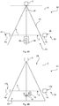
Fig. 8A shows afactory arrangement 35 according to a third embodiment. Thefactory arrangement 35 differs from thefactory arrangement 25 according to the second embodiment in that it comprises amonitoring device 30 according to a third embodiment instead of themonitoring device 20 according to the second embodiment. Themonitoring device 30 according to the third embodiment differs from themonitoring device 20 according to the second embodiment in that theradar device 5 is not part of afirst support element 31 but is rather arranged away therefrom. In particular, theradar device 5 is neither part of thefirst support element 31 nor of asecond support element 32 - Namely, the
radar device 5 is arranged such that thesafety zone 2 is located between theradar device 5 and theboundary section 3 defined by thelight curtain device 2. Thedetection axis 28 of theradar device 5 is perpendicular to theboundary section 3. - In addition to the functions of the
monitoring device 20 of the second embodiment (such as the muting and performing of a predetermined protective measure), themonitoring device 30 according to the third embodiment can also detect the material out of which a detected object is made. This material detection is performed by theradar device 5. In themonitoring device 30, the evaluation result is determined as a function of the material property of the detected object. - For example, in
Fig. 8A , acardboard box 14 is approaching theboundary section 3 from outside thesafety zone 2. Although thecardboard box 14 is within thealarm zone 23 of thedetection region 15, there is no danger because thecardboard box 14 is not a human. Thus, when themonitoring device 30 detects that thebox 14 is made of cardboard, no alarm is emitted by theprotective device 21. In addition, when the detectedobject 14 is made of cardboard or of another non-human material, the mutingdevice 22 temporarily deactivates thelight curtain device 4 such that theconveyor belt 11 is not turned off when said object touches theboundary section 3. - In the example of
Fig. 8B , a human 19 is approaching theboundary section 3 from the outside of thesafety zone 2. Theradar device 5 detects that the object is a human 19. Hence, the evaluation result indicates that a human 19 is in thealarm zone 23, thereby indicating that there is a risk of injuring the human 19. In the case that a human 19 is detected, no muting is performed. Instead, theprotection device 21 emits a warning signal and if the human 19 touches theboundary section 3, theconveyor belt 11 is further turned off, as described in view ofFig. 6A and 6B . -
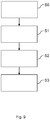
Fig. 9 shows a method for monitoring aboundary section 3 of asafety zone 2. In a step S0, themonitoring device light curtain device 4 is operated to detect if anobject boundary section 3. In a step S2, at least oneradar device 5 is contemporaneously operated for detecting a position of theobject object boundary section 3. In a step S2, an evaluation result is emitted based on a signal from theradar device 5 and optionally based on a signal from thelight curtain device 4. - Although the present invention has been described in accordance with preferred embodiments, it is obvious for the person skilled in the art that modifications are possible in all embodiments. For example, the protective measures performed by the
protection device 21 can be different and can include the emission of a visual warning signal. The shapes and sizes of the detection region, safety zone, alarm zone and/or muting zone can vary. Different protective measures can be performed by theprotection device 21 depending on the material of the detected object, the position of the object and/or its movement direction. Themonitoring device -
- 1
- monitoring device
- 2
- safety zone
- 3
- boundary section
- 4
- light curtain device
- 4a
- light emitting element
- 4b
- light receiving element
- 5
- radar device
- 5a
- radar sender
- 5b
- radar receiver
- 6
- object
- 7
- evaluation device
- 8
- cable
- 9
- light beam
- 10
- factory arrangement
- 11
- factory device
- 12
- first part
- 13
- second part
- 14
- box
- 15
- detection region
- 16
- first support element
- 17
- second support element
- 18
- direction
- 19
- human
- 20
- monitoring device
- 21
- protection device
- 22
- muting device
- 23
- alarm zone
- 24
- muting zone
- 25
- factory arrangement
- 26
- factory device
- 27
- non-dangerous zone
- 28
- detection axis
- 30
- monitoring device
- 31
- first support element
- 32
- second support element
- 35
- factory arrangement
- LDS
- light curtain device signal
- RDS
- radar device signal
- SO - S3
- method steps
Claims (14)
- A monitoring device (1, 20, 30) for monitoring a boundary section (3) of a safety zone (2) for detecting an object (6, 14, 19) at least partially entering or leaving the safety zone (2) through the boundary section (3), comprising:a light curtain device (4) for detecting an object (6, 14, 19) touching the boundary section (3);at least one radar device (5) for detecting a movement direction of the object (6, 14, 19) relative to the boundary section (3) and/or a material property of the object (6, 14, 19); andan evaluation device (7) for emitting an evaluation result based on a radar device signal (RDS) from the radar device (5) and optionally based on a light curtain device signal (LDS) from the light curtain device (4).
- The monitoring device according to claim 1, further comprising a protection device (21) for emitting a warning signal and/or performing a predetermined protective measure based on the evaluation result.
- The monitoring device according to claim 1 or 2, further comprising a muting device (22) for temporarily deactivating the protection device (21) and/or the light curtain device (4) as a function of the evaluation result.
- The monitoring device according to one of claims 1 - 3, wherein the evaluation result indicates whether the object (6, 14, 19) is inside or outside the safety zone (2), the movement direction of the object (6, 14, 19) relative to the boundary section (3) as detected by the radar device (5) and/or whether the object (6, 14, 19) is touching the boundary section (3).
- The monitoring device according to one of claims 1 to 4, wherein the radar device (5) has a detection region (15), wherein the radar device (5) and the light curtain device (4) are arranged such that the detection region (15) at least partially overlaps with the boundary section (3).
- The monitoring device according to claim 5, wherein the boundary section (3) is covered by the detection region (15).
- The monitoring device according to claim 5 or 6, wherein the detection region (15) has an elongated shape with a detection axis (28), and the radar device (5) and the light curtain device (4) are arranged such that the detection axis (28) runs parallel to the boundary section (3).
- The monitoring device according to claim 5 or 6, wherein the detection region (15) has an elongated shape with a detection axis (28), and the radar device (5) and the light curtain device (4) are arranged such that the detection axis (28) runs perpendicular to the boundary section (3).
- The monitoring device according to any one of claims 1 - 8, wherein the light curtain device (4) comprises a plurality of light emitting elements (4a) arranged on or at a first support element (16) and a plurality of light receiving elements (4b) arranged on or at a second support element (17), the boundary section (3) being between the support elements (16, 17).
- The monitoring device according to claim 9, wherein the radar device (5) comprises a radar sender (5a) and a radar receiver (5b), the radar sender (5a) and the radar receiver (5b) being arranged at or on at least one of the first and/or second support element (16, 17).
- The monitoring device according to claim 9, wherein the radar device (5) comprises a radar sender (5a) and a radar receiver (5b), the radar sender (5a) and the radar receiver (5b) being arranged at a predetermined distance from the first and the second support element (16, 17).
- The monitoring device according to any one of claims 1 - 7, wherein the safety zone (2) is situated between the radar device (5) and the light curtain device (4).
- A factory arrangement (10, 25, 35) comprising:a safety zone (2) delimited by at least one boundary section (3), wherein, in the safety zone (2), at least one factory device (11, 26) is arranged and implemented to perform a predetermined function; anda monitoring device (1, 20, 30) according to any one claims 1 - 12, implemented to detect if an object (6, 14, 19) at least partially enters or leaves the safety zone (2) through the boundary section (3).
- A method for monitoring a boundary section (3) of a safety zone (2) comprising:operating a light curtain device (4) to detect if an object (6, 14, 19) touches the boundary section (3); andcontemporaneously operating at least one radar device (5) for detecting a movement direction of the object (6, 14, 19) relative to the boundary section (3) and/or a material property of the object (6, 14, 19); andemitting an evaluation result based on a radar device signal (RDS) from the radar device (5) and optionally based on a light curtain device signal (LDS) from the light curtain device (4).
Applications Claiming Priority (2)
| Application Number | Priority Date | Filing Date | Title |
|---|---|---|---|
| IT201800002494A IT201800002494A1 (en) | 2018-02-08 | 2018-02-08 | Monitoring device for monitoring a boundary sector of a safety zone. |
| PCT/EP2019/052916 WO2019154862A1 (en) | 2018-02-08 | 2019-02-06 | Monitoring device for monitoring a boundary section of a safety zone |
Publications (2)
| Publication Number | Publication Date |
|---|---|
| EP3548792A1 EP3548792A1 (en) | 2019-10-09 |
| EP3548792B1 true EP3548792B1 (en) | 2019-12-25 |
Family
ID=62002331
Family Applications (3)
| Application Number | Title | Priority Date | Filing Date |
|---|---|---|---|
| EP19184024.8A Active EP3569920B1 (en) | 2018-02-08 | 2018-07-31 | Monitoring device and method for monitoring a monitored zone |
| EP18425060.3A Active EP3524870B2 (en) | 2018-02-08 | 2018-07-31 | Monitoring device and method for monitoring a monitored zone |
| EP19702303.9A Active EP3548792B1 (en) | 2018-02-08 | 2019-02-06 | Monitoring device for monitoring a boundary section of a safety zone |
Family Applications Before (2)
| Application Number | Title | Priority Date | Filing Date |
|---|---|---|---|
| EP19184024.8A Active EP3569920B1 (en) | 2018-02-08 | 2018-07-31 | Monitoring device and method for monitoring a monitored zone |
| EP18425060.3A Active EP3524870B2 (en) | 2018-02-08 | 2018-07-31 | Monitoring device and method for monitoring a monitored zone |
Country Status (6)
| Country | Link |
|---|---|
| US (1) | US11248744B2 (en) |
| EP (3) | EP3569920B1 (en) |
| JP (1) | JP7165741B2 (en) |
| CN (1) | CN111771079B (en) |
| IT (1) | IT201800002494A1 (en) |
| WO (1) | WO2019154862A1 (en) |
Families Citing this family (9)
| Publication number | Priority date | Publication date | Assignee | Title |
|---|---|---|---|---|
| DE102019206010A1 (en) * | 2019-04-26 | 2020-10-29 | Kuka Aktiengesellschaft | Method and system for monitoring a robot arrangement |
| DE102019127373A1 (en) * | 2019-10-10 | 2021-04-15 | Dücker conveyor systems GmbH | Safety device for securing a danger point, method for controlling a safety device, computer program product and computer-readable recording medium |
| KR20210061103A (en) * | 2019-11-19 | 2021-05-27 | 엘지전자 주식회사 | Mobile robot and method for operating the same |
| EP3886068A1 (en) * | 2020-03-23 | 2021-09-29 | Leuze electronic GmbH + Co. KG | Monitoring device and method for operating same |
| DE202020101548U1 (en) * | 2020-03-23 | 2020-04-02 | Leuze Electronic Gmbh + Co. Kg | Monitoring device for securing access to a danger zone with a safety sensor |
| DE202020102721U1 (en) * | 2020-05-14 | 2020-12-23 | Leuze Electronic Gmbh + Co. Kg | Monitoring device |
| EP3910228B1 (en) * | 2020-05-14 | 2023-08-02 | Leuze electronic GmbH + Co. KG | Monitoring device and method for operating same |
| CN113740355B (en) * | 2020-05-29 | 2023-06-20 | 清华大学 | Boundary protection method and system for ray detection robot |
| WO2023073033A1 (en) * | 2021-10-29 | 2023-05-04 | Bobst Lyon | Security system for a converting machine |
Citations (7)
| Publication number | Priority date | Publication date | Assignee | Title |
|---|---|---|---|---|
| DE4233810C2 (en) | 1992-10-07 | 2000-02-03 | Sick Ag | Monitoring device for work machines |
| WO2001059473A2 (en) | 2000-02-08 | 2001-08-16 | Cambridge Consultants Limited | Methods and apparatus for obtaining positional information |
| DE102004041821A1 (en) | 2004-08-27 | 2006-03-16 | Abb Research Ltd. | Device and method for securing a machine-controlled handling device |
| DE202004020863U1 (en) | 2004-09-17 | 2006-04-06 | Sick Ag | Safety device used in dangerous work area has upper and lower securing systems that generate signals used in determining position of object within dangerous work area |
| DE102005050824A1 (en) | 2004-11-17 | 2006-05-24 | Heidelberger Druckmaschinen Ag | Dangerous area protecting method for use in sheet rotation printing machine, involves monitoring dangerous area by sensor, detecting position of object penetrating cross section and activating machine based on detected position |
| DE102010007520B3 (en) | 2010-02-11 | 2011-05-05 | Sick Ag | Safety control with a large number of connections for sensors |
| DE102010050547A1 (en) | 2010-11-05 | 2012-05-10 | Kuka Laboratories Gmbh | Method and device for safety monitoring of a robot |
Family Cites Families (20)
| Publication number | Priority date | Publication date | Assignee | Title |
|---|---|---|---|---|
| DE10026305A1 (en) | 2000-05-26 | 2001-11-29 | Sick Ag | Opto-electronic device for monitoring protection region, has image determination unit which picks-up planar or spatial image of monitoring regions that lay near and outside the protection region |
| DE10152543A1 (en) † | 2001-10-24 | 2003-05-08 | Sick Ag | Method and device for controlling a safety-relevant function of a machine |
| JP3878604B2 (en) * | 2002-03-01 | 2007-02-07 | 株式会社日立製作所 | Detection system and security system |
| JP2005045712A (en) * | 2003-07-25 | 2005-02-17 | Mitsubishi Electric Corp | Monitor system |
| DE102005038019A1 (en) † | 2005-08-09 | 2007-02-15 | Cedes Ag | Sensor device for detecting an overhang at the loading of a carrier device |
| ITBO20050700A1 (en) * | 2005-11-18 | 2007-05-19 | Datasensor Spa | SYSTEM AND METHOD FOR THE AUTOMATIC CONTROL OF TEMPORARY DEACTIVATION OF A PHOTOELECTRIC BARRIER |
| DE102005061868A1 (en) * | 2005-12-23 | 2007-07-05 | Robert Bosch Gmbh | Device for determining an object, e.g. a water pipe in a wall, comprises a display for displaying a property of the object and a control unit for controlling the display depending on phase information |
| DE202006012351U1 (en) † | 2006-02-25 | 2006-10-19 | Leuze Lumiflex Gmbh + Co. Kg | Optical sensor e.g. light grid, for monitoring fire break in e.g. conveyor belt, has analysis unit to analyze characteristics, where region of fire break is bridged by acquiring non-safety critical objects to restrict report generation |
| DE102007041664A1 (en) * | 2006-09-04 | 2008-04-03 | Robert Bosch Gmbh | Monitoring device for machine tool i.e. stationary circular saw bench, has detection unit for detecting using condition in machine tool based on detection of human or animal tissue, and sensor arranged above or below working surface |
| DE102007013299A1 (en) † | 2007-03-06 | 2008-09-11 | Cedes Ag | Sensor device and system with a conveyor and a sensor device |
| EP2180348B1 (en) † | 2008-10-22 | 2011-02-16 | Sick Ag | Safety light curtain and corresponding method for monitoring a protection area |
| JP5473044B2 (en) * | 2009-01-31 | 2014-04-16 | 株式会社キーエンス | Safety photoelectric switch |
| US20110298579A1 (en) * | 2010-06-08 | 2011-12-08 | Cedes Safety & Automation Ag | Dynamically adaptable safety zones |
| DE102012007520B3 (en) | 2012-04-17 | 2013-08-08 | Heraeus Quarzglas Gmbh & Co. Kg | Process for the production of a cylindrical component from fluorine-containing synthetic quartz glass |
| US9910186B2 (en) | 2015-08-17 | 2018-03-06 | Rockwell Automation Safety Ag | Dynamic light curtain muting system and method |
| US10215852B1 (en) * | 2015-10-05 | 2019-02-26 | Google Llc | Robotic radar assistance |
| EP3252364B1 (en) * | 2016-05-31 | 2019-03-27 | Inxpect S.p.A. | Radar apparatus for forming a protection linear barrier and related system |
| DE102016116350B3 (en) * | 2016-09-01 | 2017-12-14 | Sick Ag | monitoring device |
| TWM589336U (en) * | 2018-08-27 | 2020-01-11 | 信錦企業股份有限公司 | Detecting system |
| DE102019206297A1 (en) * | 2019-05-02 | 2020-04-16 | elumatec AG | Access security device, profile processing center and method for securing access to a profile processing center |
-
2018
- 2018-02-08 IT IT201800002494A patent/IT201800002494A1/en unknown
- 2018-07-31 EP EP19184024.8A patent/EP3569920B1/en active Active
- 2018-07-31 EP EP18425060.3A patent/EP3524870B2/en active Active
-
2019
- 2019-02-06 EP EP19702303.9A patent/EP3548792B1/en active Active
- 2019-02-06 US US16/968,488 patent/US11248744B2/en active Active
- 2019-02-06 JP JP2020543054A patent/JP7165741B2/en active Active
- 2019-02-06 CN CN201980012478.7A patent/CN111771079B/en active Active
- 2019-02-06 WO PCT/EP2019/052916 patent/WO2019154862A1/en unknown
Patent Citations (7)
| Publication number | Priority date | Publication date | Assignee | Title |
|---|---|---|---|---|
| DE4233810C2 (en) | 1992-10-07 | 2000-02-03 | Sick Ag | Monitoring device for work machines |
| WO2001059473A2 (en) | 2000-02-08 | 2001-08-16 | Cambridge Consultants Limited | Methods and apparatus for obtaining positional information |
| DE102004041821A1 (en) | 2004-08-27 | 2006-03-16 | Abb Research Ltd. | Device and method for securing a machine-controlled handling device |
| DE202004020863U1 (en) | 2004-09-17 | 2006-04-06 | Sick Ag | Safety device used in dangerous work area has upper and lower securing systems that generate signals used in determining position of object within dangerous work area |
| DE102005050824A1 (en) | 2004-11-17 | 2006-05-24 | Heidelberger Druckmaschinen Ag | Dangerous area protecting method for use in sheet rotation printing machine, involves monitoring dangerous area by sensor, detecting position of object penetrating cross section and activating machine based on detected position |
| DE102010007520B3 (en) | 2010-02-11 | 2011-05-05 | Sick Ag | Safety control with a large number of connections for sensors |
| DE102010050547A1 (en) | 2010-11-05 | 2012-05-10 | Kuka Laboratories Gmbh | Method and device for safety monitoring of a robot |
Also Published As
| Publication number | Publication date |
|---|---|
| EP3548792A1 (en) | 2019-10-09 |
| EP3569920B1 (en) | 2020-07-22 |
| EP3524870A1 (en) | 2019-08-14 |
| EP3569920A1 (en) | 2019-11-20 |
| CN111771079A (en) | 2020-10-13 |
| JP7165741B2 (en) | 2022-11-04 |
| US20200400275A1 (en) | 2020-12-24 |
| IT201800002494A1 (en) | 2019-08-08 |
| CN111771079B (en) | 2023-07-11 |
| EP3524870B1 (en) | 2020-11-04 |
| JP2021513634A (en) | 2021-05-27 |
| EP3524870B2 (en) | 2023-08-02 |
| US11248744B2 (en) | 2022-02-15 |
| WO2019154862A1 (en) | 2019-08-15 |
Similar Documents
| Publication | Publication Date | Title |
|---|---|---|
| EP3548792B1 (en) | Monitoring device for monitoring a boundary section of a safety zone | |
| RU2459138C2 (en) | Processing machine control device | |
| JP4713888B2 (en) | Device for contact protection and method for protecting a movable member before contact | |
| US7924164B1 (en) | Method for sensing the presence of a human body part within a region of a machine tool | |
| JP5232150B2 (en) | Machine tool monitoring device | |
| US10695908B2 (en) | Access protection system | |
| US20160098910A1 (en) | Safety Device | |
| US11465283B2 (en) | Method of protecting humans in an environment of a moving machine | |
| EP3252364B1 (en) | Radar apparatus for forming a protection linear barrier and related system | |
| CN113156364A (en) | Security system and method | |
| US8639378B2 (en) | Device safety apparatus | |
| EP2533219A1 (en) | Anti-intrusion system comprising at least one microwave detecting device | |
| US20120319858A1 (en) | Emergency power-off button with proximity alarm | |
| JP7149165B2 (en) | worker protective equipment | |
| US11221104B2 (en) | Safety device for a machine and operating method | |
| TW201006603A (en) | Machine tool monitoring device | |
| JP2005234813A (en) | Railroad crossing obstacle detector | |
| EP3488984A1 (en) | Machine for working workpieces, made of wood and the like, provided with a system for detecting the presence of an operator, and operation method thereof | |
| JPH0426457Y2 (en) | ||
| US20170298540A1 (en) | Method for Operating a Bale Opener and Such a Bale Opener | |
| CN213916448U (en) | Cutting tool | |
| CN108472780A (en) | The system that detection and analysis is located at the main body in the working space of operation machine | |
| KR20220040911A (en) | Danger indicating sensor alarm device and danger indicator board | |
| CA2702560C (en) | Collision sensor for wood processing equipment |
Legal Events
| Date | Code | Title | Description |
|---|---|---|---|
| STAA | Information on the status of an ep patent application or granted ep patent |
Free format text: STATUS: UNKNOWN |
|
| STAA | Information on the status of an ep patent application or granted ep patent |
Free format text: STATUS: THE INTERNATIONAL PUBLICATION HAS BEEN MADE |
|
| PUAI | Public reference made under article 153(3) epc to a published international application that has entered the european phase |
Free format text: ORIGINAL CODE: 0009012 |
|
| STAA | Information on the status of an ep patent application or granted ep patent |
Free format text: STATUS: REQUEST FOR EXAMINATION WAS MADE |
|
| 17P | Request for examination filed |
Effective date: 20190703 |
|
| AK | Designated contracting states |
Kind code of ref document: A1 Designated state(s): AL AT BE BG CH CY CZ DE DK EE ES FI FR GB GR HR HU IE IS IT LI LT LU LV MC MK MT NL NO PL PT RO RS SE SI SK SM TR |
|
| AX | Request for extension of the european patent |
Extension state: BA ME |
|
| GRAP | Despatch of communication of intention to grant a patent |
Free format text: ORIGINAL CODE: EPIDOSNIGR1 |
|
| STAA | Information on the status of an ep patent application or granted ep patent |
Free format text: STATUS: GRANT OF PATENT IS INTENDED |
|
| GRAS | Grant fee paid |
Free format text: ORIGINAL CODE: EPIDOSNIGR3 |
|
| GRAJ | Information related to disapproval of communication of intention to grant by the applicant or resumption of examination proceedings by the epo deleted |
Free format text: ORIGINAL CODE: EPIDOSDIGR1 |
|
| GRAL | Information related to payment of fee for publishing/printing deleted |
Free format text: ORIGINAL CODE: EPIDOSDIGR3 |
|
| STAA | Information on the status of an ep patent application or granted ep patent |
Free format text: STATUS: REQUEST FOR EXAMINATION WAS MADE |
|
| GRAR | Information related to intention to grant a patent recorded |
Free format text: ORIGINAL CODE: EPIDOSNIGR71 |
|
| STAA | Information on the status of an ep patent application or granted ep patent |
Free format text: STATUS: GRANT OF PATENT IS INTENDED |
|
| INTG | Intention to grant announced |
Effective date: 20191022 |
|
| RIN1 | Information on inventor provided before grant (corrected) |
Inventor name: GRANGE, GIANMARCO Inventor name: VIVIANI, PAOLO Inventor name: ROMANO, ENZO |
|
| GRAA | (expected) grant |
Free format text: ORIGINAL CODE: 0009210 |
|
| STAA | Information on the status of an ep patent application or granted ep patent |
Free format text: STATUS: THE PATENT HAS BEEN GRANTED |
|
| INTG | Intention to grant announced |
Effective date: 20191114 |
|
| AK | Designated contracting states |
Kind code of ref document: B1 Designated state(s): AL AT BE BG CH CY CZ DE DK EE ES FI FR GB GR HR HU IE IS IT LI LT LU LV MC MK MT NL NO PL PT RO RS SE SI SK SM TR |
|
| DAV | Request for validation of the european patent (deleted) | ||
| DAX | Request for extension of the european patent (deleted) | ||
| REG | Reference to a national code |
Ref country code: GB Ref legal event code: FG4D |
|
| REG | Reference to a national code |
Ref country code: CH Ref legal event code: EP |
|
| REG | Reference to a national code |
Ref country code: DE Ref legal event code: R096 Ref document number: 602019000002 Country of ref document: DE |
|
| REG | Reference to a national code |
Ref country code: AT Ref legal event code: REF Ref document number: 1217487 Country of ref document: AT Kind code of ref document: T Effective date: 20200115 |
|
| REG | Reference to a national code |
Ref country code: IE Ref legal event code: FG4D |
|
| REG | Reference to a national code |
Ref country code: DE Ref legal event code: R026 Ref document number: 602019000002 Country of ref document: DE |
|
| PLBI | Opposition filed |
Free format text: ORIGINAL CODE: 0009260 |
|
| REG | Reference to a national code |
Ref country code: NL Ref legal event code: MP Effective date: 20191225 |
|
| PG25 | Lapsed in a contracting state [announced via postgrant information from national office to epo] |
Ref country code: FI Free format text: LAPSE BECAUSE OF FAILURE TO SUBMIT A TRANSLATION OF THE DESCRIPTION OR TO PAY THE FEE WITHIN THE PRESCRIBED TIME-LIMIT Effective date: 20191225 Ref country code: BG Free format text: LAPSE BECAUSE OF FAILURE TO SUBMIT A TRANSLATION OF THE DESCRIPTION OR TO PAY THE FEE WITHIN THE PRESCRIBED TIME-LIMIT Effective date: 20200325 Ref country code: SE Free format text: LAPSE BECAUSE OF FAILURE TO SUBMIT A TRANSLATION OF THE DESCRIPTION OR TO PAY THE FEE WITHIN THE PRESCRIBED TIME-LIMIT Effective date: 20191225 Ref country code: LV Free format text: LAPSE BECAUSE OF FAILURE TO SUBMIT A TRANSLATION OF THE DESCRIPTION OR TO PAY THE FEE WITHIN THE PRESCRIBED TIME-LIMIT Effective date: 20191225 Ref country code: LT Free format text: LAPSE BECAUSE OF FAILURE TO SUBMIT A TRANSLATION OF THE DESCRIPTION OR TO PAY THE FEE WITHIN THE PRESCRIBED TIME-LIMIT Effective date: 20191225 Ref country code: NO Free format text: LAPSE BECAUSE OF FAILURE TO SUBMIT A TRANSLATION OF THE DESCRIPTION OR TO PAY THE FEE WITHIN THE PRESCRIBED TIME-LIMIT Effective date: 20200325 Ref country code: GR Free format text: LAPSE BECAUSE OF FAILURE TO SUBMIT A TRANSLATION OF THE DESCRIPTION OR TO PAY THE FEE WITHIN THE PRESCRIBED TIME-LIMIT Effective date: 20200326 |
|
| REG | Reference to a national code |
Ref country code: LT Ref legal event code: MG4D |
|
| 26 | Opposition filed |
Opponent name: SICK AG Effective date: 20200420 |
|
| PG25 | Lapsed in a contracting state [announced via postgrant information from national office to epo] |
Ref country code: HR Free format text: LAPSE BECAUSE OF FAILURE TO SUBMIT A TRANSLATION OF THE DESCRIPTION OR TO PAY THE FEE WITHIN THE PRESCRIBED TIME-LIMIT Effective date: 20191225 Ref country code: RS Free format text: LAPSE BECAUSE OF FAILURE TO SUBMIT A TRANSLATION OF THE DESCRIPTION OR TO PAY THE FEE WITHIN THE PRESCRIBED TIME-LIMIT Effective date: 20191225 |
|
| PG25 | Lapsed in a contracting state [announced via postgrant information from national office to epo] |
Ref country code: AL Free format text: LAPSE BECAUSE OF FAILURE TO SUBMIT A TRANSLATION OF THE DESCRIPTION OR TO PAY THE FEE WITHIN THE PRESCRIBED TIME-LIMIT Effective date: 20191225 |
|
| PG25 | Lapsed in a contracting state [announced via postgrant information from national office to epo] |
Ref country code: PT Free format text: LAPSE BECAUSE OF FAILURE TO SUBMIT A TRANSLATION OF THE DESCRIPTION OR TO PAY THE FEE WITHIN THE PRESCRIBED TIME-LIMIT Effective date: 20200520 Ref country code: EE Free format text: LAPSE BECAUSE OF FAILURE TO SUBMIT A TRANSLATION OF THE DESCRIPTION OR TO PAY THE FEE WITHIN THE PRESCRIBED TIME-LIMIT Effective date: 20191225 Ref country code: RO Free format text: LAPSE BECAUSE OF FAILURE TO SUBMIT A TRANSLATION OF THE DESCRIPTION OR TO PAY THE FEE WITHIN THE PRESCRIBED TIME-LIMIT Effective date: 20191225 Ref country code: CZ Free format text: LAPSE BECAUSE OF FAILURE TO SUBMIT A TRANSLATION OF THE DESCRIPTION OR TO PAY THE FEE WITHIN THE PRESCRIBED TIME-LIMIT Effective date: 20191225 Ref country code: NL Free format text: LAPSE BECAUSE OF FAILURE TO SUBMIT A TRANSLATION OF THE DESCRIPTION OR TO PAY THE FEE WITHIN THE PRESCRIBED TIME-LIMIT Effective date: 20191225 |
|
| PG25 | Lapsed in a contracting state [announced via postgrant information from national office to epo] |
Ref country code: SK Free format text: LAPSE BECAUSE OF FAILURE TO SUBMIT A TRANSLATION OF THE DESCRIPTION OR TO PAY THE FEE WITHIN THE PRESCRIBED TIME-LIMIT Effective date: 20191225 Ref country code: SM Free format text: LAPSE BECAUSE OF FAILURE TO SUBMIT A TRANSLATION OF THE DESCRIPTION OR TO PAY THE FEE WITHIN THE PRESCRIBED TIME-LIMIT Effective date: 20191225 Ref country code: IS Free format text: LAPSE BECAUSE OF FAILURE TO SUBMIT A TRANSLATION OF THE DESCRIPTION OR TO PAY THE FEE WITHIN THE PRESCRIBED TIME-LIMIT Effective date: 20200425 |
|
| PLAX | Notice of opposition and request to file observation + time limit sent |
Free format text: ORIGINAL CODE: EPIDOSNOBS2 |
|
| PG25 | Lapsed in a contracting state [announced via postgrant information from national office to epo] |
Ref country code: DK Free format text: LAPSE BECAUSE OF FAILURE TO SUBMIT A TRANSLATION OF THE DESCRIPTION OR TO PAY THE FEE WITHIN THE PRESCRIBED TIME-LIMIT Effective date: 20191225 Ref country code: MC Free format text: LAPSE BECAUSE OF FAILURE TO SUBMIT A TRANSLATION OF THE DESCRIPTION OR TO PAY THE FEE WITHIN THE PRESCRIBED TIME-LIMIT Effective date: 20191225 Ref country code: ES Free format text: LAPSE BECAUSE OF FAILURE TO SUBMIT A TRANSLATION OF THE DESCRIPTION OR TO PAY THE FEE WITHIN THE PRESCRIBED TIME-LIMIT Effective date: 20191225 |
|
| REG | Reference to a national code |
Ref country code: AT Ref legal event code: MK05 Ref document number: 1217487 Country of ref document: AT Kind code of ref document: T Effective date: 20191225 |
|
| PG25 | Lapsed in a contracting state [announced via postgrant information from national office to epo] |
Ref country code: AT Free format text: LAPSE BECAUSE OF FAILURE TO SUBMIT A TRANSLATION OF THE DESCRIPTION OR TO PAY THE FEE WITHIN THE PRESCRIBED TIME-LIMIT Effective date: 20191225 Ref country code: FR Free format text: LAPSE BECAUSE OF NON-PAYMENT OF DUE FEES Effective date: 20200225 |
|
| PLBB | Reply of patent proprietor to notice(s) of opposition received |
Free format text: ORIGINAL CODE: EPIDOSNOBS3 |
|
| PG25 | Lapsed in a contracting state [announced via postgrant information from national office to epo] |
Ref country code: PL Free format text: LAPSE BECAUSE OF FAILURE TO SUBMIT A TRANSLATION OF THE DESCRIPTION OR TO PAY THE FEE WITHIN THE PRESCRIBED TIME-LIMIT Effective date: 20191225 |
|
| REG | Reference to a national code |
Ref country code: BE Ref legal event code: MM Effective date: 20210228 |
|
| PG25 | Lapsed in a contracting state [announced via postgrant information from national office to epo] |
Ref country code: LU Free format text: LAPSE BECAUSE OF NON-PAYMENT OF DUE FEES Effective date: 20210206 |
|
| REG | Reference to a national code |
Ref country code: DE Ref legal event code: R100 Ref document number: 602019000002 Country of ref document: DE |
|
| PG25 | Lapsed in a contracting state [announced via postgrant information from national office to epo] |
Ref country code: IE Free format text: LAPSE BECAUSE OF NON-PAYMENT OF DUE FEES Effective date: 20210206 |
|
| PLCK | Communication despatched that opposition was rejected |
Free format text: ORIGINAL CODE: EPIDOSNREJ1 |
|
| PG25 | Lapsed in a contracting state [announced via postgrant information from national office to epo] |
Ref country code: TR Free format text: LAPSE BECAUSE OF FAILURE TO SUBMIT A TRANSLATION OF THE DESCRIPTION OR TO PAY THE FEE WITHIN THE PRESCRIBED TIME-LIMIT Effective date: 20191225 |
|
| PLBN | Opposition rejected |
Free format text: ORIGINAL CODE: 0009273 |
|
| STAA | Information on the status of an ep patent application or granted ep patent |
Free format text: STATUS: OPPOSITION REJECTED |
|
| PG25 | Lapsed in a contracting state [announced via postgrant information from national office to epo] |
Ref country code: BE Free format text: LAPSE BECAUSE OF NON-PAYMENT OF DUE FEES Effective date: 20210228 |
|
| 27O | Opposition rejected |
Effective date: 20220127 |
|
| REG | Reference to a national code |
Ref country code: CH Ref legal event code: PL |
|
| PG25 | Lapsed in a contracting state [announced via postgrant information from national office to epo] |
Ref country code: LI Free format text: LAPSE BECAUSE OF NON-PAYMENT OF DUE FEES Effective date: 20220228 Ref country code: CH Free format text: LAPSE BECAUSE OF NON-PAYMENT OF DUE FEES Effective date: 20220228 |
|
| PGFP | Annual fee paid to national office [announced via postgrant information from national office to epo] |
Ref country code: IT Payment date: 20230228 Year of fee payment: 5 Ref country code: DE Payment date: 20230214 Year of fee payment: 5 |
|
| PG25 | Lapsed in a contracting state [announced via postgrant information from national office to epo] |
Ref country code: CY Free format text: LAPSE BECAUSE OF FAILURE TO SUBMIT A TRANSLATION OF THE DESCRIPTION OR TO PAY THE FEE WITHIN THE PRESCRIBED TIME-LIMIT Effective date: 20191225 |
|
| PG25 | Lapsed in a contracting state [announced via postgrant information from national office to epo] |
Ref country code: SI Free format text: LAPSE BECAUSE OF FAILURE TO SUBMIT A TRANSLATION OF THE DESCRIPTION OR TO PAY THE FEE WITHIN THE PRESCRIBED TIME-LIMIT Effective date: 20191225 |
|
| GBPC | Gb: european patent ceased through non-payment of renewal fee |
Effective date: 20230206 |
|
| PG25 | Lapsed in a contracting state [announced via postgrant information from national office to epo] |
Ref country code: GB Free format text: LAPSE BECAUSE OF NON-PAYMENT OF DUE FEES Effective date: 20230206 |
|
| PG25 | Lapsed in a contracting state [announced via postgrant information from national office to epo] |
Ref country code: GB Free format text: LAPSE BECAUSE OF NON-PAYMENT OF DUE FEES Effective date: 20230206 |