JP2010501280A - Infusion pump and method, and delivery device and method comprising the same - Google Patents
Infusion pump and method, and delivery device and method comprising the same Download PDFInfo
- Publication number
- JP2010501280A JP2010501280A JP2009525745A JP2009525745A JP2010501280A JP 2010501280 A JP2010501280 A JP 2010501280A JP 2009525745 A JP2009525745 A JP 2009525745A JP 2009525745 A JP2009525745 A JP 2009525745A JP 2010501280 A JP2010501280 A JP 2010501280A
- Authority
- JP
- Japan
- Prior art keywords
- piston
- housing portion
- delivery device
- chamber
- housing
- Prior art date
- Legal status (The legal status is an assumption and is not a legal conclusion. Google has not performed a legal analysis and makes no representation as to the accuracy of the status listed.)
- Pending
Links
Images


Classifications
-
- G—PHYSICS
- G01—MEASURING; TESTING
- G01F—MEASURING VOLUME, VOLUME FLOW, MASS FLOW OR LIQUID LEVEL; METERING BY VOLUME
- G01F11/00—Apparatus requiring external operation adapted at each repeated and identical operation to measure and separate a predetermined volume of fluid or fluent solid material from a supply or container, without regard to weight, and to deliver it
- G01F11/02—Apparatus requiring external operation adapted at each repeated and identical operation to measure and separate a predetermined volume of fluid or fluent solid material from a supply or container, without regard to weight, and to deliver it with measuring chambers which expand or contract during measurement
- G01F11/021—Apparatus requiring external operation adapted at each repeated and identical operation to measure and separate a predetermined volume of fluid or fluent solid material from a supply or container, without regard to weight, and to deliver it with measuring chambers which expand or contract during measurement of the piston type
- G01F11/029—Apparatus requiring external operation adapted at each repeated and identical operation to measure and separate a predetermined volume of fluid or fluent solid material from a supply or container, without regard to weight, and to deliver it with measuring chambers which expand or contract during measurement of the piston type provided with electric controlling means
-
- A—HUMAN NECESSITIES
- A61—MEDICAL OR VETERINARY SCIENCE; HYGIENE
- A61M—DEVICES FOR INTRODUCING MEDIA INTO, OR ONTO, THE BODY; DEVICES FOR TRANSDUCING BODY MEDIA OR FOR TAKING MEDIA FROM THE BODY; DEVICES FOR PRODUCING OR ENDING SLEEP OR STUPOR
- A61M5/00—Devices for bringing media into the body in a subcutaneous, intra-vascular or intramuscular way; Accessories therefor, e.g. filling or cleaning devices, arm-rests
- A61M5/14—Infusion devices, e.g. infusing by gravity; Blood infusion; Accessories therefor
- A61M5/1413—Modular systems comprising interconnecting elements
-
- A—HUMAN NECESSITIES
- A61—MEDICAL OR VETERINARY SCIENCE; HYGIENE
- A61M—DEVICES FOR INTRODUCING MEDIA INTO, OR ONTO, THE BODY; DEVICES FOR TRANSDUCING BODY MEDIA OR FOR TAKING MEDIA FROM THE BODY; DEVICES FOR PRODUCING OR ENDING SLEEP OR STUPOR
- A61M5/00—Devices for bringing media into the body in a subcutaneous, intra-vascular or intramuscular way; Accessories therefor, e.g. filling or cleaning devices, arm-rests
- A61M5/14—Infusion devices, e.g. infusing by gravity; Blood infusion; Accessories therefor
- A61M5/142—Pressure infusion, e.g. using pumps
- A61M5/14212—Pumping with an aspiration and an expulsion action
- A61M5/14216—Reciprocating piston type
-
- A—HUMAN NECESSITIES
- A61—MEDICAL OR VETERINARY SCIENCE; HYGIENE
- A61M—DEVICES FOR INTRODUCING MEDIA INTO, OR ONTO, THE BODY; DEVICES FOR TRANSDUCING BODY MEDIA OR FOR TAKING MEDIA FROM THE BODY; DEVICES FOR PRODUCING OR ENDING SLEEP OR STUPOR
- A61M5/00—Devices for bringing media into the body in a subcutaneous, intra-vascular or intramuscular way; Accessories therefor, e.g. filling or cleaning devices, arm-rests
- A61M5/14—Infusion devices, e.g. infusing by gravity; Blood infusion; Accessories therefor
- A61M5/142—Pressure infusion, e.g. using pumps
- A61M5/14244—Pressure infusion, e.g. using pumps adapted to be carried by the patient, e.g. portable on the body
- A61M5/14248—Pressure infusion, e.g. using pumps adapted to be carried by the patient, e.g. portable on the body of the skin patch type
-
- A—HUMAN NECESSITIES
- A61—MEDICAL OR VETERINARY SCIENCE; HYGIENE
- A61M—DEVICES FOR INTRODUCING MEDIA INTO, OR ONTO, THE BODY; DEVICES FOR TRANSDUCING BODY MEDIA OR FOR TAKING MEDIA FROM THE BODY; DEVICES FOR PRODUCING OR ENDING SLEEP OR STUPOR
- A61M5/00—Devices for bringing media into the body in a subcutaneous, intra-vascular or intramuscular way; Accessories therefor, e.g. filling or cleaning devices, arm-rests
- A61M5/14—Infusion devices, e.g. infusing by gravity; Blood infusion; Accessories therefor
- A61M5/142—Pressure infusion, e.g. using pumps
- A61M5/145—Pressure infusion, e.g. using pumps using pressurised reservoirs, e.g. pressurised by means of pistons
- A61M5/1452—Pressure infusion, e.g. using pumps using pressurised reservoirs, e.g. pressurised by means of pistons pressurised by means of pistons
- A61M5/14566—Pressure infusion, e.g. using pumps using pressurised reservoirs, e.g. pressurised by means of pistons pressurised by means of pistons with a replaceable reservoir for receiving a piston rod of the pump
-
- G—PHYSICS
- G01—MEASURING; TESTING
- G01F—MEASURING VOLUME, VOLUME FLOW, MASS FLOW OR LIQUID LEVEL; METERING BY VOLUME
- G01F11/00—Apparatus requiring external operation adapted at each repeated and identical operation to measure and separate a predetermined volume of fluid or fluent solid material from a supply or container, without regard to weight, and to deliver it
- G01F11/02—Apparatus requiring external operation adapted at each repeated and identical operation to measure and separate a predetermined volume of fluid or fluent solid material from a supply or container, without regard to weight, and to deliver it with measuring chambers which expand or contract during measurement
- G01F11/021—Apparatus requiring external operation adapted at each repeated and identical operation to measure and separate a predetermined volume of fluid or fluent solid material from a supply or container, without regard to weight, and to deliver it with measuring chambers which expand or contract during measurement of the piston type
- G01F11/023—Apparatus requiring external operation adapted at each repeated and identical operation to measure and separate a predetermined volume of fluid or fluent solid material from a supply or container, without regard to weight, and to deliver it with measuring chambers which expand or contract during measurement of the piston type with provision for varying the stroke of the piston
-
- G—PHYSICS
- G01—MEASURING; TESTING
- G01F—MEASURING VOLUME, VOLUME FLOW, MASS FLOW OR LIQUID LEVEL; METERING BY VOLUME
- G01F11/00—Apparatus requiring external operation adapted at each repeated and identical operation to measure and separate a predetermined volume of fluid or fluent solid material from a supply or container, without regard to weight, and to deliver it
- G01F11/02—Apparatus requiring external operation adapted at each repeated and identical operation to measure and separate a predetermined volume of fluid or fluent solid material from a supply or container, without regard to weight, and to deliver it with measuring chambers which expand or contract during measurement
- G01F11/04—Apparatus requiring external operation adapted at each repeated and identical operation to measure and separate a predetermined volume of fluid or fluent solid material from a supply or container, without regard to weight, and to deliver it with measuring chambers which expand or contract during measurement of the free-piston type
- G01F11/06—Apparatus requiring external operation adapted at each repeated and identical operation to measure and separate a predetermined volume of fluid or fluent solid material from a supply or container, without regard to weight, and to deliver it with measuring chambers which expand or contract during measurement of the free-piston type with provision for varying the stroke of the piston
-
- A—HUMAN NECESSITIES
- A61—MEDICAL OR VETERINARY SCIENCE; HYGIENE
- A61M—DEVICES FOR INTRODUCING MEDIA INTO, OR ONTO, THE BODY; DEVICES FOR TRANSDUCING BODY MEDIA OR FOR TAKING MEDIA FROM THE BODY; DEVICES FOR PRODUCING OR ENDING SLEEP OR STUPOR
- A61M5/00—Devices for bringing media into the body in a subcutaneous, intra-vascular or intramuscular way; Accessories therefor, e.g. filling or cleaning devices, arm-rests
- A61M5/14—Infusion devices, e.g. infusing by gravity; Blood infusion; Accessories therefor
- A61M5/142—Pressure infusion, e.g. using pumps
- A61M5/14244—Pressure infusion, e.g. using pumps adapted to be carried by the patient, e.g. portable on the body
- A61M2005/14268—Pressure infusion, e.g. using pumps adapted to be carried by the patient, e.g. portable on the body with a reusable and a disposable component
-
- A—HUMAN NECESSITIES
- A61—MEDICAL OR VETERINARY SCIENCE; HYGIENE
- A61M—DEVICES FOR INTRODUCING MEDIA INTO, OR ONTO, THE BODY; DEVICES FOR TRANSDUCING BODY MEDIA OR FOR TAKING MEDIA FROM THE BODY; DEVICES FOR PRODUCING OR ENDING SLEEP OR STUPOR
- A61M2205/00—General characteristics of the apparatus
- A61M2205/02—General characteristics of the apparatus characterised by a particular materials
- A61M2205/0266—Shape memory materials
-
- A—HUMAN NECESSITIES
- A61—MEDICAL OR VETERINARY SCIENCE; HYGIENE
- A61M—DEVICES FOR INTRODUCING MEDIA INTO, OR ONTO, THE BODY; DEVICES FOR TRANSDUCING BODY MEDIA OR FOR TAKING MEDIA FROM THE BODY; DEVICES FOR PRODUCING OR ENDING SLEEP OR STUPOR
- A61M2205/00—General characteristics of the apparatus
- A61M2205/82—Internal energy supply devices
- A61M2205/8206—Internal energy supply devices battery-operated
-
- A—HUMAN NECESSITIES
- A61—MEDICAL OR VETERINARY SCIENCE; HYGIENE
- A61M—DEVICES FOR INTRODUCING MEDIA INTO, OR ONTO, THE BODY; DEVICES FOR TRANSDUCING BODY MEDIA OR FOR TAKING MEDIA FROM THE BODY; DEVICES FOR PRODUCING OR ENDING SLEEP OR STUPOR
- A61M2209/00—Ancillary equipment
- A61M2209/04—Tools for specific apparatus
- A61M2209/045—Tools for specific apparatus for filling, e.g. for filling reservoirs
-
- A—HUMAN NECESSITIES
- A61—MEDICAL OR VETERINARY SCIENCE; HYGIENE
- A61M—DEVICES FOR INTRODUCING MEDIA INTO, OR ONTO, THE BODY; DEVICES FOR TRANSDUCING BODY MEDIA OR FOR TAKING MEDIA FROM THE BODY; DEVICES FOR PRODUCING OR ENDING SLEEP OR STUPOR
- A61M5/00—Devices for bringing media into the body in a subcutaneous, intra-vascular or intramuscular way; Accessories therefor, e.g. filling or cleaning devices, arm-rests
- A61M5/36—Devices for bringing media into the body in a subcutaneous, intra-vascular or intramuscular way; Accessories therefor, e.g. filling or cleaning devices, arm-rests with means for eliminating or preventing injection or infusion of air into body
- A61M5/38—Devices for bringing media into the body in a subcutaneous, intra-vascular or intramuscular way; Accessories therefor, e.g. filling or cleaning devices, arm-rests with means for eliminating or preventing injection or infusion of air into body using hydrophilic or hydrophobic filters
- A61M5/385—Devices for bringing media into the body in a subcutaneous, intra-vascular or intramuscular way; Accessories therefor, e.g. filling or cleaning devices, arm-rests with means for eliminating or preventing injection or infusion of air into body using hydrophilic or hydrophobic filters using hydrophobic filters
-
- Y—GENERAL TAGGING OF NEW TECHNOLOGICAL DEVELOPMENTS; GENERAL TAGGING OF CROSS-SECTIONAL TECHNOLOGIES SPANNING OVER SEVERAL SECTIONS OF THE IPC; TECHNICAL SUBJECTS COVERED BY FORMER USPC CROSS-REFERENCE ART COLLECTIONS [XRACs] AND DIGESTS
- Y10—TECHNICAL SUBJECTS COVERED BY FORMER USPC
- Y10T—TECHNICAL SUBJECTS COVERED BY FORMER US CLASSIFICATION
- Y10T29/00—Metal working
- Y10T29/49—Method of mechanical manufacture
- Y10T29/49826—Assembling or joining
Landscapes
- Health & Medical Sciences (AREA)
- Heart & Thoracic Surgery (AREA)
- Engineering & Computer Science (AREA)
- Hematology (AREA)
- Vascular Medicine (AREA)
- Life Sciences & Earth Sciences (AREA)
- Anesthesiology (AREA)
- Biomedical Technology (AREA)
- Animal Behavior & Ethology (AREA)
- Fluid Mechanics (AREA)
- General Physics & Mathematics (AREA)
- Physics & Mathematics (AREA)
- General Health & Medical Sciences (AREA)
- Public Health (AREA)
- Veterinary Medicine (AREA)
- Dermatology (AREA)
- Infusion, Injection, And Reservoir Apparatuses (AREA)
- External Artificial Organs (AREA)
Abstract
送達デバイスは、互いに選択的に係合および係脱する、耐久ハウジング部分および分離可能な使い捨てハウジング部分を備えている。使い捨てハウジング部分は、患者利用者に固定し、所定期間使用した後に処分することができる。ポンプデバイスを含む、通常患者利用者または注入媒体と接触するコンポーネントは、所定の使用後に処分するために使い捨てハウジング部分によって支持されており、耐久ハウジング部分は、貯蔵容器からの注入媒体の送達を制御する電子部品、および駆動デバイスおよび駆動リンクなどの他のコンポーネントを支持する。 The delivery device includes a durable housing portion and a separable disposable housing portion that selectively engages and disengages from each other. The disposable housing portion can be secured to the patient user and disposed of after a predetermined period of use. Components that normally contact the patient user or the infusion medium, including the pump device, are supported by a disposable housing portion for disposal after a given use, and the durable housing portion controls the delivery of the infusion medium from the storage container And other components such as drive devices and drive links.
Description
本発明の実施形態は、患者利用者に注入媒体を送達する注入媒体送達デバイスに関し、送達デバイスはベース部分と、ベース部分に接続可能な耐久部分とを備えており、ベース部分は耐久部分から分離させ、1回以上の指定回数使用された後に処分することができる。ベース部分は貯蔵容器を支持し、耐久部分は、貯蔵容器から流体を選択的に駆動させるように、貯蔵容器に動作可能に結合された駆動デバイスを支持する。 Embodiments of the invention relate to an infusion medium delivery device for delivering an infusion medium to a patient user, the delivery device comprising a base portion and a durable portion connectable to the base portion, the base portion being separated from the durable portion. And can be disposed of after being used one or more times. The base portion supports the storage container and the durable portion supports a drive device operably coupled to the storage container to selectively drive fluid from the storage container.
本発明は、本願に引用して援用する、2006年10月27日に出願した「Infusion Pumps And Methods And Delivery Devices And Methods With Same」という表題の米国特許出願第11/589,323号(代理人整理番号0398)に関する。それに加えて、本発明は、全体を引用して援用し、それにより優先権出願日を請求する、2006年8月23日に出願した「Infusion Pumps And Methods And Delivery Devices And Methods With Same」という表題の米国特許出願第60/839,741号に関する。本発明はまた、それぞれ本願に引用して援用し、それにより優先権出願日を請求する、2005年5月6日に出願した米国特許仮出願第60/678,290号、および2005年8月23日に出願した「Infusion Device And Method With Disposable Portion」という表題の米国特許出願第11/211,095号に関する。本発明はまた、それぞれの内容本願に引用して援用する、2006年8月23日に出願した「Infusion Medium Delivery Device And Method For Driving Plunger In Reservoir」という表題の米国同時係属出願第60/839,821号(代理人整理番号047711.0381)、2006年8月23日に出願した「Infusion Medium Delivery Device And Method For Driving Plunger In Reservoir」という表題の米国同時係属出願第60/839,822号(代理人整理番号047711.0382)、2006年8月23日に出願した「Infusion Medium Delivery Device And Method With Compressible Or Curved Reservoir Or Conduit」という表題の同時係属出願第60/839,832号(代理人整理番号047711.0383)、および2006年8月23日に出願した「Infusion Medium Delivery Device,System And Method With Needle Inserter And Needle Inserter Device And Method」という表題の米国同時係属特許出願第60/839,840号(代理人整理番号047711.0384)に関する。本発明の実施形態はまた、それぞれ本願に引用して援用する、(i)2006年10月27日に出願した「Infusion Medium Delivery Device and Method with Drive Device for Driving Plunger in Reservoir」という表題の米国特許出願第11/588,832号(代理人整理番号047711.0387)、(ii)2006年10月27日に出願した「Infusion Medium Delivery Device and Method with Compressible or Curved Reservoir or Conduit」という表題の米国特許出願第11/588,847号(代理人整理番号047711.0390)、(iii)2006年10月27日に出願した「Infusion Medium Delivery System,Device and Method with Needle Inserter and Needle Inserter Device and Method」という表題の米国特許仮出願第60/854,829号(代理人整理番号047711.0401)、(iv)2006年8月23日に出願した「Systems And Methods Allowing For Reservoir Filling And Infusion Medium Delivery」という表題の米国特許出願第11/588,875号(代理人整理番号047711.0393)、(v)2006年11月20日に出願した「Systems and Methods Allowing for Reservoir filling and Infusion Medium Delivery」という表題の米国特許出願(番号未割当)(代理人整理番号047711.0397)、(vi)2006年11月20日に出願した「Systems and Methods Allowing for Reservoir filling and Infusion Medium Delivery」という表題の米国特許出願(番号未割当)(代理人整理番号047711.0396)、(vii)2006年11月20日に出願した「Systems and Methods Allowing for Reservoir filling and Infusion Medium Delivery」という表題の米国特許出願(番号未割当)(代理人整理番号047711.0395)、(viii)2006年11月20日に出願した「Systems and Methods Allowing for Reservoir Filling and Infusion Medium Delivery」という表題の米国特許出願(番号未割当)(代理人整理番号047711.0394)、(ix)2006年11月22日に出願した「Infusion Medium Delivery Device and Method and Drive Device for Driving Plunger in Reservoir」という表題の米国特許出願(番号未割当)(代理人整理番号047711.0389)、(x)2006年11月22日に出願した「Infusion Medium Delivery Device and Method and Drive Device for Driving Plunger in Reservoir」という表題の米国特許出願(番号未割当)(代理人整理番号047711.0388)に関する。
The present invention is a US patent application Ser. No. 11 / 589,323 entitled “Infusion Pumps And Methods And Delivery Devices And Methods With Same” filed Oct. 27, 2006, incorporated herein by reference. No. 0398). In addition, the present invention is entitled "Infusion Pumps And Methods And Delivery Devices And Methods With Same", filed August 23, 2006, which is incorporated by reference in its entirety and thereby claims the priority filing date. U.S. Patent Application No. 60 / 839,741. The present invention also incorporates US Provisional Application No. 60 / 678,290, filed May 6, 2005, and August 2005, each of which is hereby incorporated by reference and thus claims the priority filing date. It relates to US patent application Ser. No. 11 / 212,095 entitled “Infusion Device And Method Disposable Portion” filed on the 23rd. The present invention also includes US
いくつかの慢性疾病は、現代の医療技術では、全治療期間中連続して、または全治療期間内の特定の時点または時間間隔で、患者体内に薬剤または他の物質を送達することにより治療されうる。例えば、糖尿病は、定められた量のインスリンを適切な時間に患者に送達することにより一般に治療される慢性疾病である。患者にインスリン療法を施す一般的な方法としては、手動操作される注射器およびインスリンペンを通してインスリンを送達する方法が挙げられる。他の現代的なシステムでは、制御された量のインスリンを患者に送達するためにプログラム可能なポンプを使用している。 Some chronic illnesses are treated in modern medical technology by delivering drugs or other substances into the patient's body either continuously during the entire treatment period or at a specific time or interval within the entire treatment period. sell. For example, diabetes is a chronic disease that is commonly treated by delivering a defined amount of insulin to a patient at an appropriate time. Common methods of administering insulin therapy to a patient include delivering insulin through a manually operated syringe and insulin pen. Other modern systems use programmable pumps to deliver controlled amounts of insulin to the patient.
ポンプ型送達デバイスは、外部デバイス(患者利用者に接続する)または埋め込み型デバイス(患者利用者体内に埋め込む)内に構成されている。外部ポンプ型送達デバイスは、ほぼ静止している場所(例えば、病院または診療所の)で使用するように設計されたデバイス、さらには歩行中または携帯用途(患者利用者が持ち運ぶ)に合わせて構成されたデバイスを含む。いくつかの外部ポンプ型送達デバイスの実施例は、それぞれ本願に引用して援用する、2005年8月23日に出願した「Infusion Device And Method With Disposable Portion」という表題の米国特許出願第11/211,095号、および「Exchangeable Electronic Cards For Infusion Devices」という表題の国際公開第01/70307号(PCT/US01/09139)(それぞれ本発明の譲受人により所有されている)、「Components And Methods For Patient Infusion Device」という表題の国際公開第04/030716号(PCT/US2003/028769)、「Dispenser Components And Methods For Infusion Device」という表題の国際公開第04/030717号(PCT/US2003/029019)、「Method For Advising Patients Concerning Doses Of Insulin」という表題の米国特許出願公開第2005/0065760号、および「Wearable Self−Contained Drug Infusion Device」という表題の米国特許第6,589,229号において説明されている。
The pump-type delivery device is configured in an external device (connected to the patient user) or an implantable device (implanted in the patient user's body). External pump-type delivery devices are designed for use in nearly stationary locations (eg, in hospitals or clinics), as well as configured for walking or portable use (carried by patient users) Devices included. Examples of several external pump type delivery devices are described in US patent application Ser. No. 11/211, entitled “Infusion Device And Method Disposable Portion” filed Aug. 23, 2005, each incorporated herein by reference. , 095, and International Publication No. 01/70307 (PCT / US01 / 09139), each entitled “Exchangeable Electronic Cards for Infusion Devices” (each owned by the assignee of the present invention), “Components And Authents Feds International Publication No. 04/030716 (PCT / US2003 / 028769) entitled “Infusion Device” International Publication No. 04/030717 (PCT / US2003 / 029019) entitled “Dispensers Components And Methods For Infusion Devices”, “Methods For Advertising
外部ポンプ型送達デバイスは、例えば、適切な中空管を通じて、患者利用者に流体連絡で接続することができる。中空管は、患者利用者の皮膚を穿刺し、注入媒体を患者利用者に送り込むように設計された中空針に接続させることができる。別の方法では、中空管は、カニューレとして、またはそこを通して患者利用者に直接接続できる。 The external pump type delivery device can be connected in fluid communication to the patient user, for example, through a suitable hollow tube. The hollow tube can be connected to a hollow needle designed to puncture the patient user's skin and deliver the infusion medium to the patient user. Alternatively, the hollow tube can be connected directly to the patient user as or through a cannula.
中空管が、患者利用者の皮膚を刺し通す中空針を通じて患者利用者に接続される状況では、手動で針を患者利用者に挿入すると、患者利用者にいくぶん外傷を残すことになりうる。したがって、患者利用者に針を挿入するのを手助けする挿入機構が製作されており、これにより、針は、ばねにより強制的に引き込み位置から伸展位置に素早く移動する。送達デバイスに内蔵された挿入機構の実施例は、本願に引用して援用する、2005年8月23日に出願した「Infusion Device And Method With Disposable Portion」という表題の米国特許出願第11/211,095号(本発明の譲受人に譲渡)に記載されている。挿入具の他の実施例は、本願に引用して援用する、「Insertion Device For An Insertion Set And Method Of Using The Same」という表題の米国特許出願公開第2002/0022855号(本発明の譲受人に譲渡)に記載されている。針が伸展位置に移動すると、針は手による遅い針の挿入に比べて患者利用者に引き起こされる外傷の程度が比較的小さい1回の比較的急激的な運動で素早く患者利用者の皮膚に押し通される。 In situations where the hollow tube is connected to the patient user through a hollow needle that pierces the patient user's skin, manual insertion of the needle into the patient user may leave some trauma to the patient user. Accordingly, an insertion mechanism has been created to assist the patient user in inserting the needle, whereby the needle is forced to move quickly from the retracted position to the extended position by the spring. An example of an insertion mechanism incorporated in a delivery device is described in US patent application Ser. No. 11/212, entitled “Infusion Device And Method Disposable Portion,” filed Aug. 23, 2005, which is incorporated herein by reference. No. 095 (assigned to the assignee of the present invention). Another example of an insert is described in US Patent Application Publication No. 2002/0022855, entitled “Insertion Device For An Insert Set And Method Of Using The Same”, which is incorporated herein by reference. (Transfer). When the needle moves to the extended position, the needle quickly pushes against the patient's skin with a single, relatively abrupt movement that causes a relatively small degree of trauma to the patient user compared to slow insertion of the needle by hand. Passed.
注射器およびインスリンペンに比べて、ポンプ型送達デバイスは、インスリンの正確な投与量を計算し、日中または夜間のいつの時間でも患者利用者に自動的に送達できるという点で、患者利用者にとって著しく都合がよいと思われる。さらに、グルコースセンサまたはモニタと併用した場合、インスリンポンプを自動制御し、感知または監視されている血糖レベルに基づき、適切な必要時期に注入媒体の適切な投与を行うことができる。 Compared to syringes and insulin pens, pump-type delivery devices are notable for patient users in that they can calculate the exact dose of insulin and automatically deliver it to the patient user at any time of day or night. It seems convenient. In addition, when used in conjunction with a glucose sensor or monitor, the insulin pump can be automatically controlled to deliver the appropriate infusion medium at the appropriate time based on the blood glucose level being sensed or monitored.
ポンプ型送達デバイスは、糖尿病などのさまざまな種類の病状の現代的医学的治療の重要な態様となっている。ポンプ技術が改善され、医者および患者利用者が、このようなデバイスに馴染んでくるにつれ、外部医学的注入ポンプ治療の普及が進み、今後10年間にかなり拡大するものと予想される。 Pump-type delivery devices have become an important aspect of modern medical treatment of various types of medical conditions such as diabetes. As pump technology is improved and physicians and patient users become familiar with such devices, the spread of external medical infusion pump therapy is expected to expand significantly over the next decade.
本発明の実施形態は概して、医療患者などの受容者に注入媒体を送達するための送達デバイス、システムおよび方法に関する。このような送達デバイスは、それぞれ動作のために係合および取り付けるように構成された第1および第2のハウジング部分(本明細書では、それぞれ耐久ハウジング部分および使い捨てハウジング部分と呼ぶ)を備えることができる。使い捨てハウジング部分は、注入媒体貯蔵容器、および動作中に注入媒体および/または患者利用者と接触する他のコンポーネントを含むことができる。使い捨てハウジング部分はまた、本明細書で記載した実施形態によるポンプデバイスを含むことができる。耐久ハウジング部分は、これに限らないが、駆動デバイス、駆動リンク、電子回路、およびいくつかの実施形態では、電力源を含む、送達デバイスの通常動作中に注入媒体または患者利用者と接触しないコンポーネントを含む、あるいは支持することができる。 Embodiments of the present invention generally relate to a delivery device, system and method for delivering an infusion medium to a recipient, such as a medical patient. Such a delivery device comprises first and second housing portions (referred to herein as durable housing portions and disposable housing portions, respectively) configured to engage and attach for operation. it can. The disposable housing portion can include an infusion medium storage container and other components that come into contact with the infusion medium and / or patient user during operation. The disposable housing portion can also include a pump device according to the embodiments described herein. The durable housing portion includes, but is not limited to, a drive device, drive link, electronic circuit, and in some embodiments, a component that does not contact the infusion medium or patient user during normal operation of the delivery device, including a power source. Can be included or supported.
使い捨てハウジング部分は、耐久ハウジング部分から係脱および分離させることができ、それによって使い捨てハウジング部分は、ある期間の使用後に、または1回または所定回数の使用の後に簡単に処分することができる。使い捨てハウジング部分からの係脱および分離後に、耐久ハウジング部分は、別の動作のために別の使い捨てハウジング部分(新しい、改装された、利用者充填された、事前充填された、再充填された、または作り直しされた使い捨てハウジング部分)に係合および動作可能に接続させることができる。 The disposable housing portion can be disengaged and separated from the durable housing portion so that the disposable housing portion can be easily disposed of after a period of use or after one or a predetermined number of uses. After disengagement and separation from the disposable housing part, the durable housing part is separated from another disposable housing part (new, refurbished, user-filled, pre-filled, re-filled, Or can be engaged and operably connected to a re-made disposable housing part).
したがって、本発明の例示的な実施形態により利用者に注入媒体を送達する送達デバイスは、利用者に固定されるようになっている使い捨てハウジング部分、および耐久ハウジング部分を処分することなく使い捨てハウジング部分を処分することを可能にするように、使い捨てハウジング部分と選択的に係合し、そこから係脱するように構成された耐久ハウジング部分を備えることができる。本明細書に記載の送達デバイス実施形態は、貯蔵容器から注入媒体を引く、および/または注入媒体を注射部位に運ぶのにさまざまなポンプ実施形態のいずれか1つを利用することができる。 Accordingly, a delivery device for delivering an infusion medium to a user according to an exemplary embodiment of the present invention includes a disposable housing portion adapted to be secured to the user, and a disposable housing portion without disposing of the durable housing portion. A durable housing portion that is configured to selectively engage and disengage from the disposable housing portion. The delivery device embodiments described herein can utilize any one of a variety of pump embodiments to pull the infusion medium from the storage container and / or carry the infusion medium to the injection site.
例えば、本明細書に記載したような送達デバイスは、使い捨てハウジング部分によって支持され、駆動シャフトを通して駆動デバイスによって動作可能に駆動されるように配置されたポンプデバイスを備えることができる。駆動シャフトは、第1の方向、および第1の方向と反対の第2の方向の移動のために、耐久ハウジング部分によって支持することができる。駆動デバイスは、駆動シャフトを第1の方向に選択的に移動して、ポンプデバイスを駆動させるように、駆動シャフトに動作可能に連結することができる。 For example, a delivery device as described herein can comprise a pump device supported by a disposable housing portion and arranged to be operably driven by a drive device through a drive shaft. The drive shaft can be supported by the durable housing portion for movement in a first direction and in a second direction opposite the first direction. The drive device can be operably coupled to the drive shaft to selectively move the drive shaft in the first direction to drive the pump device.
本発明の一実施形態によるポンプデバイスは、注入媒体を入れる可変容積を有する流体部分を含む内部を有するピストンチャンバを備えている。ポンプデバイスの入口ポートは、ピストンチャンバの内部容積と流体流連絡して設けられている。入口ポートは、貯蔵容器と流体流連絡するように、貯蔵容器と接続するように構成されている。 A pump device according to an embodiment of the invention includes a piston chamber having an interior that includes a fluid portion having a variable volume for receiving an infusion medium. The inlet port of the pump device is provided in fluid flow communication with the internal volume of the piston chamber. The inlet port is configured to connect with the storage container in fluid flow communication with the storage container.
ポンプデバイスの出口ポートは、ピストンチャンバの内部容積と流体流連絡するように設けられている。押し板は、第1の方向および第1の方向と反対の第2の方向への前後移動のために支持されており、押し板は、使い捨てハウジング部分および耐久ハウジング部分が互いに係合している場合に、駆動シャフトが第1の方向に移動されると押し板を第1の方向の方向に移動させ、駆動シャフトが第2の方向に移動されると第2の方向への押し板の移動を可能にするように、駆動シャフトと動作可能に係合する位置に配置されている。 The outlet port of the pump device is provided in fluid flow communication with the internal volume of the piston chamber. The push plate is supported for back-and-forth movement in a first direction and a second direction opposite the first direction, wherein the push plate engages the disposable housing portion and the durable housing portion with each other. In this case, when the drive shaft is moved in the first direction, the push plate is moved in the first direction, and when the drive shaft is moved in the second direction, the push plate is moved in the second direction. So as to be operatively engaged with the drive shaft.
ピストンヘッドは、ピストンチャンバの流体部分の容積を変えるように、引き込み位置と動作位置の間でのピストンチャンバ内の移動のために支持されている。ピストンヘッドは、第1の方向への押し板の移動での引き込み位置から動作位置までの移動のために、押し板に固定関係で動作可能に結合されている。ピストンチャンバが注入流体を入れている場合、ピストンヘッドが引き込み位置から動作位置まで移動されて、注入媒体をピストンチャンバの流体部分から出口ポートを通して押し込むように圧力をピストンチャンバ内に与えるときに、ピストンチャンバの流体部分の容積は少なくなる。逆に、入口ポートが貯蔵容器と流体流連絡して接続されている場合、ピストンヘッドが引き込み位置から動作位置まで移動されて、注入流体をピストンチャンバの流体部分内に入口ポートを通して引くように圧力をピストンチャンバ内に与えるときに、ピストンチャンバの流体部分の容積が大きくなる。 The piston head is supported for movement within the piston chamber between a retracted position and an operating position so as to change the volume of the fluid portion of the piston chamber. The piston head is operably coupled to the push plate in a fixed relationship for movement from the retracted position to the operating position in the movement of the push plate in the first direction. When the piston chamber contains the infusion fluid, the piston head is moved from the retracted position to the operating position to apply pressure into the piston chamber to force the infusion medium from the fluid portion of the piston chamber through the outlet port. The volume of the fluid portion of the chamber is reduced. Conversely, when the inlet port is connected in fluid flow communication with the storage vessel, the piston head is moved from the retracted position to the operating position to pressure the infused fluid through the inlet port into the fluid portion of the piston chamber. Is applied to the piston chamber, the volume of the fluid portion of the piston chamber increases.
本発明の一実施形態による送達デバイスは、使い捨てハウジング部分および耐久ハウジング部分が互いに係合している場合に、駆動シャフトが第2の方向に移動されるときに、押し板を第2の方向に移動させるのに十分なバイアス力を押し板に第2の方向に加えるように、押し板に動作可能に結合されたバイアス部材を備えている。同じまたは別の実施形態では、押し板はピストンロッドによってピストンヘッドに結合され、ピストンチャンバはピストンロッドがこれを通して延びる溝路部に開口している。流体が溝路部を通過するのを抑制するために、シールが設けられている。 A delivery device according to an embodiment of the present invention provides a push plate in a second direction when the drive shaft is moved in a second direction when the disposable housing portion and the durable housing portion are engaged with each other. A biasing member is operably coupled to the push plate so as to apply a biasing force sufficient to move the push plate in the second direction. In the same or another embodiment, the push plate is coupled to the piston head by a piston rod, and the piston chamber opens into a channel through which the piston rod extends. A seal is provided to prevent fluid from passing through the channel.
同じまたは別の実施形態では、送達デバイスは、注入媒体を入れる内部容積を有する貯蔵容器と、貯蔵容器の内部容積をポンプデバイスの入口ポートと流体流連絡して接続させる導管とを備えている。貯蔵容器は、使い捨てハウジング部分によって支持することができる。 In the same or another embodiment, the delivery device comprises a storage container having an internal volume for receiving the infusion medium and a conduit that connects the internal volume of the storage container in fluid flow communication with the inlet port of the pump device. The storage container can be supported by a disposable housing part.
例示的な実施形態によると、使い捨てハウジング部分は、ポンプデバイスが中に置かれる内部容積を有するハウジング構造を備えている。また、使い捨てハウジング部分のハウジング構造は、開口部を有する壁面を備えている。押し板は、使い捨てハウジング部分および耐久ハウジング部分が互いに係合している場合に、使い捨てハウジング部分のハウジング構造の壁面内の開口部を通して、駆動シャフトによって作用されるように位置決めされた表面を有する。 According to an exemplary embodiment, the disposable housing portion comprises a housing structure having an internal volume in which the pump device is placed. Further, the housing structure of the disposable housing portion includes a wall surface having an opening. The push plate has a surface positioned to be acted upon by the drive shaft through an opening in the wall of the housing structure of the disposable housing portion when the disposable housing portion and the durable housing portion are engaged with each other.
別の例示的な実施形態によると、耐久ハウジング部分は、駆動デバイスが中に置かれる内部容積を有するハウジング構造を備えている。また、耐久ハウジング部分のハウジング構造は、駆動シャフトがこれを通して延びる開口部を有する壁面を備えている。駆動シャフトは、使い捨てハウジング部分および耐久ハウジング部分が互いに係合している場合に、押し板の表面と係合するように耐久ハウジング部分の外部に位置決めされた端部を有する。 According to another exemplary embodiment, the durable housing portion comprises a housing structure having an internal volume in which the drive device is placed. The housing structure of the durable housing portion also includes a wall surface having an opening through which the drive shaft extends. The drive shaft has an end positioned external to the durable housing portion to engage the surface of the push plate when the disposable housing portion and the durable housing portion are engaged with each other.
本発明の別の態様によると、流体媒体を運ぶためにポンプデバイスが設けられている。ポンプデバイスは、流体媒体を入れる可変容積を有する流体部分を含む内部を有するピストンチャンバを有する。入口ポートは、ピストンチャンバの内部容積と流体流連絡して設けられている。入口ポートは、流体媒体を流体媒体源からピストンチャンバの内部容積内に受けるように、流体媒体源と接続するように構成されている。出口ポートは、ピストンチャンバの内部容積と流体流連絡するように設けられている。 According to another aspect of the invention, a pump device is provided to carry the fluid medium. The pump device has a piston chamber having an interior that includes a fluid portion having a variable volume for receiving a fluid medium. An inlet port is provided in fluid flow communication with the internal volume of the piston chamber. The inlet port is configured to connect with the fluid medium source to receive the fluid medium from the fluid medium source into the internal volume of the piston chamber. The outlet port is provided in fluid flow communication with the internal volume of the piston chamber.
上記ポンプ実施形態では、押し板は、第1の方向および第1の方向と反対の第2の方向への前後移動のために支持されている。押し板は、駆動シャフトが第1の方向に移動されると押し板を第1の方向の方向に移動させ、駆動シャフトが第2の方向に移動されると第2の方向への押し板の移動を可能にするように、駆動シャフトと動作可能に係合する位置に配置されている。ピストンヘッドは、ピストンチャンバの流体部分の容積を変えるように、引き込み位置と動作位置の間でのピストンチャンバ内の移動のために支持されている。ピストンヘッドは、第1の方向への押し板の移動での引き込み位置から動作位置までの移動のために、押し板に固定関係で動作可能に結合されている。 In the pump embodiment, the push plate is supported for back-and-forth movement in the first direction and the second direction opposite to the first direction. The push plate moves the push plate in the first direction when the drive shaft is moved in the first direction, and moves the push plate in the second direction when the drive shaft is moved in the second direction. A position is operatively engaged with the drive shaft to allow movement. The piston head is supported for movement within the piston chamber between a retracted position and an operating position so as to change the volume of the fluid portion of the piston chamber. The piston head is operably coupled to the push plate in a fixed relationship for movement from the retracted position to the operating position in the movement of the push plate in the first direction.
ピストンチャンバが注入流体を入れている場合、ピストンヘッドが引き込み位置から動作位置まで移動されて、注入流体をピストンチャンバの流体部分から出口ポートを通して押し込むように圧力をピストンチャンバ内に与えるときに、ピストンチャンバの流体部分の容積は少なくなる。入口ポートが流体媒体源と流体流連絡して接続されている場合、ピストンヘッドが引き込み位置から動作位置まで移動されて、流体媒体をピストンチャンバの流体部分内に入口ポートを通して引くように圧力をピストンチャンバ内に与えるときに、ピストンチャンバの流体部分の容積が大きくなる。 When the piston chamber contains infusion fluid, the piston head is moved from the retracted position to the operating position to apply pressure into the piston chamber to force the infusion fluid from the fluid portion of the piston chamber through the outlet port. The volume of the fluid portion of the chamber is reduced. When the inlet port is connected in fluid flow communication with the fluid medium source, the piston head is moved from the retracted position to the operating position to apply pressure to draw the fluid medium through the inlet port into the fluid portion of the piston chamber. When applied into the chamber, the volume of the fluid portion of the piston chamber increases.
本発明の一実施形態によるポンプデバイスは、使い捨てハウジング部分および耐久ハウジング部分が互いに係合している場合に、駆動シャフトが第2の方向に移動されるときに、押し板を第2の方向に移動させるのに十分なバイアス力を押し板に第2の方向に加えるように、押し板に動作可能に結合されたバイアス部材を有する。同じまたは別の実施形態では、押し板はピストンロッドによってピストンヘッドに結合され、ピストンチャンバはピストンロッドがこれを通して延びる溝路部に開口している。流体が溝路部を通過するのを抑制するために、シールが設けられている。 A pump device according to an embodiment of the present invention moves the push plate in the second direction when the drive shaft is moved in the second direction when the disposable housing portion and the durable housing portion are engaged with each other. A biasing member is operably coupled to the push plate to apply a biasing force sufficient to move the push plate in the second direction. In the same or another embodiment, the push plate is coupled to the piston head by a piston rod, and the piston chamber opens into a channel through which the piston rod extends. A seal is provided to prevent fluid from passing through the channel.
本発明の別の実施形態は、注入媒体を利用者に送達する送達デバイスを作る方法に関する。本発明の一実施形態による方法は、利用者に固定されるようになっている使い捨てハウジング部分を設けるステップと、耐久ハウジング部分を処分することなく使い捨てハウジング部分を処分することを可能にするように、使い捨てハウジング部分と選択的に係合し、そこから係脱するように構成された耐久ハウジング部分を設けるステップとを含んでいる。この方法はさらに、第1の方向、および第1の方向と反対の第2の方向の移動のために、耐久ハウジング部分上に駆動シャフトを支持するステップと、駆動シャフトを第1の方向に選択的に移動させるように、駆動デバイスを駆動シャフトに動作可能に接続させるステップと、ポンプデバイスを使い捨てハウジング部分上に支持するステップとを含んでいる。 Another embodiment of the invention relates to a method of making a delivery device that delivers an infusion medium to a user. A method according to an embodiment of the present invention provides a step of providing a disposable housing portion that is adapted to be secured to a user, and allows the disposable housing portion to be disposed without disposing of the durable housing portion. Providing a durable housing portion configured to selectively engage and disengage from the disposable housing portion. The method further includes supporting the drive shaft on the durable housing portion for movement in the first direction and in a second direction opposite the first direction, and selecting the drive shaft in the first direction. Operatively connecting the drive device to the drive shaft and moving the pump device on the disposable housing portion for general movement.
ポンプデバイスを支持するステップは、注入媒体を入れる可変容積を有する流体部分を含む内部を有するピストンチャンバを設けるステップと、入口ポートをピストンチャンバの内部容積と流体流連絡して接続させるステップであって、入口ポートは、貯蔵容器と流体流連絡するように、貯蔵容器と接続するように構成されているステップと、出口ポートをピストンチャンバの内部容積と流体流連絡するように接続させるステップとを含んでいる。それに加えて、ポンプデバイスを支持するステップは、第1の方向および第1の方向と反対の第2の方向への前後移動のために押し板を支持するステップと、使い捨てハウジング部分および耐久ハウジング部分が互いに係合している場合に、駆動シャフトが第1の方向に移動されると押し板を第1の方向の方向に移動させ、駆動シャフトが第2の方向に移動されると第2の方向への押し板の移動を可能にするように、駆動シャフトと動作可能に係合する位置に押し板を配置するステップとを含んでいる。 Supporting the pump device includes providing a piston chamber having an interior that includes a fluid portion having a variable volume for receiving an infusion medium, and connecting the inlet port in fluid flow communication with the internal volume of the piston chamber. The inlet port is configured to connect with the storage container to be in fluid flow communication with the storage container; and the outlet port is connected to be in fluid flow communication with the internal volume of the piston chamber. It is out. In addition, the step of supporting the pump device comprises supporting the push plate for back and forth movement in a first direction and a second direction opposite to the first direction, and a disposable housing portion and a durable housing portion. Are engaged with each other, when the drive shaft is moved in the first direction, the push plate is moved in the first direction, and when the drive shaft is moved in the second direction, the second Positioning the push plate in a position operatively engaged with the drive shaft so as to allow movement of the push plate in the direction.
ポンプデバイスを支持するステップはさらに、ピストンチャンバの流体部分の容積を変えるように、引き込み位置と動作位置の間での移動のためにピストンヘッドをピストンチャンバ内に配置するステップと、第1の方向への押し板の移動での引き込み位置から動作位置までの移動のために、ピストンヘッドを押し板に固定関係で結合させるステップとを含んでいる。このような方法では、ピストンチャンバが注入流体を入れている場合、ピストンヘッドが引き込み位置から動作位置まで移動されて、注入媒体をピストンチャンバの流体部分から出口ポートを通して押し込むように圧力をピストンチャンバ内に与えるときに、ピストンチャンバの流体部分の容積は少なくなる。それに加えて、入口ポートが貯蔵容器と流体流連絡して接続されている場合、ピストンヘッドが引き込み位置から動作位置まで移動されて、注入流体をピストンチャンバの流体部分内に入口ポートを通して引くように圧力をピストンチャンバ内に与えるときに、ピストンチャンバの流体部分の容積が大きくなる。 The step of supporting the pump device further includes positioning the piston head in the piston chamber for movement between the retracted position and the operating position to change the volume of the fluid portion of the piston chamber; Coupling the piston head to the push plate in a fixed relationship for movement from the retracted position to the operating position in the movement of the push plate to. In such a method, when the piston chamber contains infused fluid, the piston head is moved from the retracted position to the operating position to apply pressure within the piston chamber so as to push the infusion medium from the fluid portion of the piston chamber through the outlet port. The volume of the fluid portion of the piston chamber is reduced. In addition, when the inlet port is connected in fluid flow communication with the storage vessel, the piston head is moved from the retracted position to the operating position to draw the injected fluid through the inlet port into the fluid portion of the piston chamber. When pressure is applied into the piston chamber, the volume of the fluid portion of the piston chamber increases.
本発明の別の実施形態による方法は、使い捨てハウジング部分および耐久ハウジング部分が互いに係合している場合に、駆動シャフトが第2の方向に移動されるときに、押し板を第2の方向に移動させるのに十分なバイアス力を押し板に第2の方向に加えるバイアス部材を結合させるステップを含んでいる。同じまたは別の実施形態では、この方法は、注入媒体を入れる内部容積を有する貯蔵容器を設けるステップと、導管を貯蔵容器の内部容積およびポンプデバイスの入口ポートと流体流連絡して接続させるステップとを含んでいる。貯蔵容器は、使い捨てハウジング部分上に支持することができる。 According to another embodiment of the present invention, the disposable plate portion and the durable housing portion are engaged with each other when the drive shaft is moved in the second direction and the push plate is moved in the second direction. Coupling a biasing member that applies a biasing force in a second direction to the push plate sufficient to move it. In the same or another embodiment, the method includes providing a storage container having an internal volume for receiving the infusion medium, and connecting the conduit in fluid flow communication with the internal volume of the storage container and the inlet port of the pump device. Is included. The storage container can be supported on the disposable housing portion.
本発明の実施形態による押し板を支持するステップは、押し板をピストンロッドによってピストンヘッドに結合させるステップと、ピストンロッドをピストンチャンバの開口部を通して溝路部まで伸展させるステップと、流体が溝路部を通過するのを抑制するようにシールを設けるステップとを含んでいる。同じまたは別の実施形態による方法は、ポンプデバイスを使い捨てハウジング部分の内部容積に置くステップと、使い捨てハウジング部分の壁面内に開口部を設けるステップと、使い捨てハウジング部分および耐久ハウジング部分が互いに係合している場合に、使い捨てハウジング部分のハウジング構造の壁面内の開口部を通して、駆動シャフトによって作用されるような位置に押し板の表面を配置するステップとを含んでいる。 Supporting the push plate according to an embodiment of the present invention includes coupling the push plate to the piston head by a piston rod, extending the piston rod through the opening of the piston chamber to the groove, Providing a seal so as to prevent passage through the part. A method according to the same or another embodiment comprises the steps of placing the pump device in the interior volume of the disposable housing part, providing an opening in the wall of the disposable housing part, and engaging the disposable housing part and the durable housing part with each other. The surface of the push plate through the opening in the wall of the housing structure of the disposable housing portion in a position to be acted upon by the drive shaft.
同じまたは別の実施形態による方法は、耐久ハウジング部分の内部容積に駆動デバイスを置くステップと、耐久ハウジング部分の壁面に開口部を設けるステップと、耐久ハウジング部分の壁面の開口部を通して駆動シャフトを伸展させるステップとを含んでいる。このような実施形態では、駆動シャフトは、使い捨てハウジング部分および耐久ハウジング部分が互いに係合している場合に、押し板の表面と係合するように耐久ハウジング部分の外部に位置決めされた端部を有する。 A method according to the same or another embodiment comprises the steps of placing a drive device in the interior volume of the durable housing portion, providing an opening in the wall of the durable housing portion, and extending the drive shaft through the opening in the wall of the durable housing portion. Step. In such an embodiment, the drive shaft has an end positioned externally of the durable housing portion to engage the surface of the push plate when the disposable housing portion and the durable housing portion are engaged with each other. Have.
本明細書に記載した実施形態のいずれかによる方法は、使い捨てハウジング部分および耐久ハウジング部分が互いに係合している場合に、耐久ハウジング部分および使い捨てハウジング部分の一方に少なくとも1つの可撓性爪を、また耐久ハウジング部分および使い捨てハウジング部分のもう一方に少なくとも1つの可撓性爪を受ける形状を有する少なくとも1つの受け入れ部を設けるステップを含むことができる。本明細書に記載された実施形態のいずれかによる方法はまた、耐久ハウジング部分内に電気制御回路を含めることができ、耐久ハウジング部分および使い捨てハウジング部分が係合している場合、電気制御回路は利用者への貯蔵容器からの注入媒体の送達を行うように駆動デバイスを制御する。本明細書に記載した実施形態のいずれかによる方法は、例えば接着材料を使い捨てハウジング部分および耐久ハウジング部分の少なくとも一方の底部表面に塗布して、使い捨てハウジング部分または耐久ハウジング部分を利用者の皮膚に固定することによって、使い捨てハウジング部分および耐久ハウジング部分の少なくとも一方の底部表面を利用者の皮膚に固定するステップを含むことができる。この方法はさらに、ベース部分の底部表面が利用者の皮膚に固定された場合に中空針またはカニューレを利用者の皮膚に挿入することができる注射部位を設けるステップと、導管を中空針またはカニューレおよびポンプデバイスの出口ポートと流体流連絡して接続させるステップとを含むことができる。別の実施形態は、一方向弁を導管内に接続させるステップを含んでいる。さらに別の実施形態は、導管をポンプデバイスの入口ポートに接続させるステップと、一方向弁を導管内に接続させるステップとを含んでいる。 A method according to any of the embodiments described herein includes at least one flexible pawl on one of the durable housing portion and the disposable housing portion when the disposable housing portion and the durable housing portion are engaged with each other. And providing at least one receiving portion having a shape for receiving at least one flexible pawl on the other of the durable housing portion and the disposable housing portion. The method according to any of the embodiments described herein can also include an electrical control circuit within the durable housing portion, and when the durable housing portion and the disposable housing portion are engaged, the electrical control circuit is The drive device is controlled to deliver the infusion medium from the storage container to the user. A method according to any of the embodiments described herein includes, for example, applying an adhesive material to a bottom surface of at least one of the disposable housing portion and the durable housing portion to place the disposable housing portion or the durable housing portion on the user's skin. Fixing may include fixing the bottom surface of at least one of the disposable housing portion and the durable housing portion to the user's skin. The method further includes providing an injection site through which a hollow needle or cannula can be inserted into the user's skin when the bottom surface of the base portion is secured to the user's skin; And in fluid flow connection with the outlet port of the pump device. Another embodiment includes connecting a one-way valve into the conduit. Yet another embodiment includes connecting a conduit to the inlet port of the pump device and connecting a one-way valve within the conduit.
本明細書に記載した送達デバイスの別の実施例は、使い捨てハウジング部分によって支持され、駆動シャフトによって動作可能に駆動されるように配置された、本発明の一実施形態によるポンプデバイスを備えており、駆動シャフトは、第1の方向および第1の方向と反対の第2の方向に移動するように耐久ハウジング部分によって支持されている。送達デバイスはまた、駆動シャフトを第1の方向に選択的に移動させて、ポンプデバイスを駆動させるように、駆動シャフトに動作可能に接続された駆動デバイスを備えることができる。 Another example of a delivery device described herein comprises a pump device according to an embodiment of the present invention supported by a disposable housing portion and arranged to be operably driven by a drive shaft. The drive shaft is supported by the durable housing portion for movement in a first direction and a second direction opposite the first direction. The delivery device can also include a drive device operably connected to the drive shaft to selectively move the drive shaft in the first direction to drive the pump device.
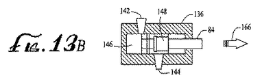
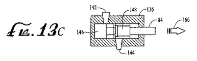
本発明の一実施形態によるポンプデバイスは、ほぼ直線状長手方向軸を有するピストン溝路を備えたハウジングを備えている。ハウジングはまた、溝路と流体流連絡し、貯蔵容器と接続するように構成された入口ポートと、溝路と流体流連絡し、注射部位と流体流連絡して接続するように構成された出口ポートとを有する。ピストンは、ピストン溝路内に配置され、互いに対する移動を制限するように互いに結合された第1のピストン部および第2のピストン部を有する。第2のピストン部は、耐久ハウジング部分および使い捨てハウジング部分が係合されている場合に、駆動シャフトと動作可能に係合する表面を有する。 A pump device according to an embodiment of the present invention includes a housing with a piston channel having a generally linear longitudinal axis. The housing also includes an inlet port configured to be in fluid flow communication with the channel and connected to the storage container, and an outlet configured to be in fluid flow communication with the channel and in fluid flow communication with the injection site. Port. The piston has a first piston portion and a second piston portion disposed in the piston channel and coupled to each other to limit movement relative to each other. The second piston portion has a surface that operably engages the drive shaft when the durable housing portion and the disposable housing portion are engaged.
ピストンは、充填、引張、および分配位置の間のピストン溝路の長手方向軸に沿った駆動シャフトの移動で移動可能である。充填位置では、第1および第2のピストン部は、第1と第2のピストン部の間に容積を有するチャンバを形成するように離れており、チャンバは入口ポートと流体流連絡して位置合わせされている。引張位置では、第1および第2のピストン部は離れており、第1と第2のピストン部の間に形成されたチャンバは、入口ポートおよび出口ポートとの流体流連絡から外れ、入口ポートと出口ポートの間で溝路内に配置されている。分配位置では、第1と第2のピストン部の間のチャンバは、出口ポートと流体流連絡して位置合わせされている。 The piston is movable by movement of the drive shaft along the longitudinal axis of the piston channel between fill, pull and dispense positions. In the filling position, the first and second piston portions are spaced apart to form a chamber having a volume between the first and second piston portions, and the chamber is in fluid flow communication with the inlet port and aligned. Has been. In the tensioned position, the first and second piston portions are separated, and the chamber formed between the first and second piston portions is out of fluid flow communication with the inlet and outlet ports, Located in the channel between the exit ports. In the dispensing position, the chamber between the first and second piston portions is aligned in fluid flow communication with the outlet port.
本発明の別の実施形態による送達デバイスはまた、注入媒体を入れる内部容積を有する貯蔵容器を備えている。導管は、貯蔵容器の内部容積をポンプデバイスのハウジングの入口ポートと流体流連絡して接続させる。貯蔵容器は、使い捨てハウジング部分によって支持することができる。 The delivery device according to another embodiment of the invention also includes a storage container having an internal volume for containing the infusion medium. A conduit connects the internal volume of the storage container in fluid flow communication with the inlet port of the pump device housing. The storage container can be supported by a disposable housing part.
上記実施形態のいずれにおいても、第1および第2のピストン部はそれぞれ、第1および第2のピストン部のもう一方の端部表面と向かい合った端部表面を有することができる。このような実施形態では、第2のピストン部は、中空内部と、一端部に中空内部内への開口部とを有する。第2のピストン部の中空内部は、停止表面を有する。第1のピストン部は、第2のピストン部の中空内部内に延びる延長部分を備え、第1および第2のピストン部の端部表面が完全に離れており、ピストンが充填位置にある場合に、第2のピストン部の中空内部の停止表面と係合する停止表面を有する。別の方法では、第1のピストン部は、中空内部と、一端部に中空内部内への開口部とを有し、ここで中空内部は停止表面を有し、第2のピストン部は第1のピストン部の中空内部内に延びる延長部分を備え、ここで延長部分は、第1および第2のピストン部の端部表面が完全に離れており、ピストンが充填位置にある場合に、第1のピストン部の中空内部の停止表面と係合する停止表面を有する。 In any of the above embodiments, the first and second piston portions may each have an end surface that faces the other end surface of the first and second piston portions. In such an embodiment, the second piston part has a hollow interior and an opening into the hollow interior at one end. The hollow interior of the second piston portion has a stop surface. The first piston part comprises an extension extending into the hollow interior of the second piston part, when the end surfaces of the first and second piston parts are completely separated and the piston is in the filling position. And a stop surface that engages a stop surface in the hollow interior of the second piston portion. In another method, the first piston portion has a hollow interior and an opening at one end to the hollow interior, where the hollow interior has a stop surface and the second piston portion is the first piston portion. An extension portion extending into the hollow interior of the first piston portion, wherein the extension portion is first when the end surfaces of the first and second piston portions are completely separated and the piston is in the filling position. And a stop surface that engages a stop surface in the hollow interior of the piston portion.
上に記載したように上記実施形態のいずれにおいても、第1および第2のピストン部はそれぞれ、第1および第2のピストン部のもう一方の端部表面と向かい合った端部表面を有することができる。それに加えて、第1および第2のピストン部の端部表面は、ピストンが分配位置にある場合に互いに当接するように配置されている。 As described above, in any of the above embodiments, the first and second piston portions may each have an end surface facing the other end surface of the first and second piston portions. it can. In addition, the end surfaces of the first and second piston parts are arranged to abut each other when the pistons are in the dispensing position.
また、上記実施形態のいずれにおいても、第2のピストン部は、第1のピストン部から離れて面する端部表面を有することができる。このような実施形態では、使い捨てハウジング部分は、ポンプデバイスが中に置かれる内部容積を有するハウジング構造を備えており、また開口部を有する壁面を備えている。駆動シャフトと動作可能に係合するための第2のピストン部の表面は、第1のピストン部から離れて面する第2のピストン部の端部表面であり、使い捨てハウジング部分および耐久ハウジング部分が互いに係合している場合に、使い捨てハウジング部分のハウジング構造の壁面の開口部を通して駆動シャフトによって作用されるように位置決めされている。 In any of the above embodiments, the second piston portion may have an end surface that faces away from the first piston portion. In such an embodiment, the disposable housing portion comprises a housing structure having an internal volume in which the pump device is placed and comprises a wall surface having an opening. The surface of the second piston portion for operative engagement with the drive shaft is the end surface of the second piston portion facing away from the first piston portion, the disposable housing portion and the durable housing portion being When engaged with each other, they are positioned to be acted upon by the drive shaft through an opening in the wall of the housing structure of the disposable housing portion.
このような一実施形態では、耐久ハウジング部分は、駆動デバイスが中に置かれる内部容積を有するハウジング構造と、開口部を有する壁面とを備えることができる。駆動シャフトは、耐久ハウジング部分の壁面の開口部を通して延びている。またこのような一実施形態では、駆動シャフトは、使い捨てハウジング部分および耐久ハウジング部分が互いに係合している場合に、第2のピストン部の端部表面と動作可能に接続するように、耐久ハウジング部分の外部に位置決めされた端部を有することができる。 In one such embodiment, the durable housing portion may comprise a housing structure having an internal volume in which the drive device is placed and a wall surface having an opening. The drive shaft extends through an opening in the wall of the durable housing portion. Also in such an embodiment, the drive shaft may be operatively connected to the end surface of the second piston portion when the disposable housing portion and the durable housing portion are engaged with each other. It can have an end positioned outside the part.
流体媒体を運ぶポンプデバイスを作る方法の別の実施形態は、ピストン溝路をハウジング内に設けるステップであって、ピストン溝路はほぼ直線長手方向軸を有するステップと、ピストン溝路と流体流連絡し、流体媒体源と接続するように構成された入口ポートを設けるステップと、ピストン溝路と流体流連絡する出口ポートを設けるステップとを含んでいる。このような方法はさらに、互いに対する移動を制限するように互いに結合された第1のピストン部および第2のピストン部を有するピストンを設けるステップであって、第2のピストン部は駆動力を駆動シャフトから受ける表面を有するステップと、駆動力が駆動シャフトから受けられる場合に、充填、引張および分配位置の間でのピストン溝路の長手方向軸に沿った移動のために、ピストン溝路内でピストンを支持するステップとを含んでいる。充填位置では、第1および第2のピストン部は、第1と第2のピストン部の間に容積を有するチャンバを形成するように離れており、チャンバは入口ポートと流体流連絡して位置合わせされている。引張位置では、第1および第2のピストン部は離れており、第1と第2のピストン部の間に形成されたチャンバは、入口ポートおよび出口ポートとの流体流連絡から外れ、入口ポートと出口ポートの間で溝路内に配置されている。分配位置では、第1と第2のピストン部の間のチャンバは、出口ポートと流体流連絡して位置合わせされている。第1および第2のピストン部の端部表面は、ピストンが分配位置にある場合に、互いに当接するように配置することができる。 Another embodiment of a method of making a pump device that carries a fluid medium includes providing a piston channel in the housing, the piston channel having a generally linear longitudinal axis, and fluid flow communication with the piston channel. And providing an inlet port configured to connect to a fluid medium source and providing an outlet port in fluid flow communication with the piston channel. Such a method further includes providing a piston having a first piston portion and a second piston portion coupled to each other to limit movement relative to each other, the second piston portion driving a driving force. In the piston channel for movement along the longitudinal axis of the piston channel between the filling, pulling and dispensing positions when the driving force is received from the drive shaft and a step having a surface received from the shaft Supporting the piston. In the filling position, the first and second piston portions are spaced apart to form a chamber having a volume between the first and second piston portions, and the chamber is in fluid flow communication with the inlet port and aligned. Has been. In the tensioned position, the first and second piston portions are separated, and the chamber formed between the first and second piston portions is out of fluid flow communication with the inlet and outlet ports, Located in the channel between the exit ports. In the dispensing position, the chamber between the first and second piston portions is aligned in fluid flow communication with the outlet port. The end surfaces of the first and second piston portions can be arranged to abut each other when the piston is in the dispensing position.
このような方法の別の実施形態によると、ピストンをピストン溝路内に支持するステップは、第1および第2のピストン部それぞれを端部間に配置するステップを含み、各ピストン部の端部表面がもう一方のピストン部の端部表面と向かい合っている。それに加えて、第1および第2のピストン部を有するピストンを設けるステップは、中空内部と、一端部に中空内部内への開口部とを備えた第2のピストン部を設けるステップであって、中空内部が停止表面を有するステップと、第2のピストン部の中空内部内に延びる延長部分を備える第1のピストン部を設けるステップであって、延長部分は、第1および第2のピストン部の端部表面が完全に離れており、ピストンが充填位置にある場合に、第2のピストン部の中空内部の停止表面と係合する停止表面を有するステップとを含んでいる。別の方法では、第1および第2のピストン部を有するピストンを設けるステップは、中空内部と、一端部に中空内部内への開口部とを備えた第1のピストン部を設けるステップであって、中空内部が停止表面を有するステップと、第1のピストン部の中空内部内に延びる延長部分を備えた第2のピストン部を設けるステップであって、延長部分は、第1および第2のピストン部の端部表面が完全に離れており、ピストンが充填位置にある場合に、第1のピストン部の中空内部の停止表面と係合する停止表面を有するステップとを含むことができる。 According to another embodiment of such a method, the step of supporting the piston in the piston channel includes the step of disposing each of the first and second piston portions between the ends, the end of each piston portion. The surface faces the end surface of the other piston part. In addition, the step of providing a piston having first and second piston portions is the step of providing a second piston portion having a hollow interior and an opening into the hollow interior at one end. Providing a first piston portion with a hollow interior having a stop surface and an extension portion extending into the hollow interior of the second piston portion, the extension portions of the first and second piston portions; And having a stop surface that engages a stop surface in the hollow interior of the second piston portion when the end surfaces are completely separated and the piston is in the filling position. In another method, providing a piston having first and second piston portions includes providing a first piston portion having a hollow interior and an opening into the hollow interior at one end. Providing a second piston portion with an extension portion extending into the hollow interior of the first piston portion, wherein the extension portion comprises first and second pistons. And having a stop surface that engages a stop surface in the hollow interior of the first piston portion when the end surface of the portion is completely separated and the piston is in the filling position.
別の方法実施形態はまた、利用者に固定されるようになっている表面を有する使い捨てハウジング部分を設けるステップと、耐久ハウジング部分を処分することなく使い捨てハウジング部分を処分することを可能にするように、使い捨てハウジング部分および耐久ハウジング部分が動作のために互いに選択的に係合し、互いに係脱するのを可能にするような接続構造で使い捨てハウジング部分および耐久ハウジング部分を設けるステップとを含んでいる。このような方法はさらに、ほぼ直線寸法で移動するために、耐久ハウジング部分で駆動シャフトを支持するステップと、ほぼ直線寸法で駆動シャフトを選択的に移動させるように、駆動デバイスを駆動シャフトに動作可能に接続させるステップとを含んでいる。このような方法はさらに、使い捨てハウジング部分でポンプハウジングを支持するステップを含んでおり、ポンプハウジングは、ほぼ直線長手方向軸を備えたピストン溝路を有する。 Another method embodiment also provides for providing a disposable housing portion having a surface adapted to be secured to a user and disposing of the disposable housing portion without disposing of the durable housing portion. Providing the disposable housing portion and the durable housing portion with a connection structure that allows the disposable housing portion and the durable housing portion to selectively engage and disengage from each other for operation. Yes. Such a method further includes supporting the drive shaft with a durable housing portion to move in a substantially linear dimension and operating the drive device on the drive shaft to selectively move the drive shaft in a substantially linear dimension. Step of enabling connection. Such a method further includes the step of supporting the pump housing with a disposable housing portion, the pump housing having a piston channel with a generally linear longitudinal axis.
また、このような別の方法は、ピストン溝路まで延び、流体媒体源に接続するように構成された入口ポートを設けるステップと、ピストン溝路と流体流連絡する出口ポートを設けるステップとを含んでいる。それに加えて、このような方法は、使い捨てハウジング部分および耐久ハウジング部分が動作のために係合されている場合に、駆動シャフトから駆動力を受ける表面を有するピストンを設けるステップと、駆動シャフトから力を受ける際に、充填位置と分配位置の間でのピストン溝路の長手方向軸に沿った移動のためにピストンをピストン溝路内に支持するステップとを含んでいる。充填位置では、ピストンは、入口ポートを通したピストン溝路およびピストンチャンバ内への流体流連絡を可能にする位置に移動される。分配位置では、ピストンは、入口ポートを通した流体流連絡を妨害し、ピストンチャンバの容積を少なくして、ピストンチャンバ内の流体を出口ポートから外に押し出す位置に移動される。 Another such method also includes providing an inlet port extending to the piston channel and configured to connect to a fluid medium source and providing an outlet port in fluid flow communication with the piston channel. It is out. In addition, such a method includes providing a piston having a surface that receives a driving force from the drive shaft when the disposable housing portion and the durable housing portion are engaged for operation, and a force from the drive shaft. Receiving the piston in the piston channel for movement along the longitudinal axis of the piston channel between the filling position and the dispensing position. In the fill position, the piston is moved to a position that allows fluid flow communication through the inlet port into the piston channel and into the piston chamber. In the dispensing position, the piston is moved to a position that obstructs fluid flow communication through the inlet port, reduces the volume of the piston chamber, and pushes fluid in the piston chamber out of the outlet port.
さらに別の実施形態では、この方法は、ピストンチャンバおよび出口ポートと流体流連絡する出口チャンバを備えたポンプデバイスのハウジングを設けるステップを含んでいる。このような実施形態はさらに、ピストンチャンバと出口チャンバの間に、ピストンチャンバから出口チャンバまでの流体流を可能にし、出口チャンバからピストンチャンバまでの流体流を抑制するように配置された一方向弁を配置するステップを含んでいる。別の実施形態では、一方向弁は、ダックビル弁構造である。 In yet another embodiment, the method includes providing a pump device housing with an outlet chamber in fluid flow communication with the piston chamber and the outlet port. Such an embodiment is further arranged between the piston chamber and the outlet chamber to allow fluid flow from the piston chamber to the outlet chamber and to restrict fluid flow from the outlet chamber to the piston chamber. Including the step of arranging. In another embodiment, the one-way valve is a duckbill valve structure.
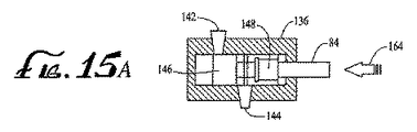
本発明の別の実施形態によるポンプデバイスはまた、ほぼ直線長手方向軸を有するピストン溝路を備えたハウジングを備えている。入口ポートは、ピストン溝路まで延び、貯蔵容器に接続するように構成されている。ピストンチャンバは、溝路と流体流連絡している。出口ポートはまた、ピストン溝路と流体流連絡しており、注射部位と流体流連絡して接続するように構成されている。 The pump device according to another embodiment of the present invention also includes a housing with a piston channel having a generally linear longitudinal axis. The inlet port extends to the piston channel and is configured to connect to the storage container. The piston chamber is in fluid flow communication with the channel. The outlet port is also in fluid flow communication with the piston channel and is configured to connect in fluid flow communication with the injection site.
ピストンは、ピストン溝路内に置かれ、耐久ハウジング部分および使い捨てハウジング部分が係合する場合に、駆動シャフトから駆動力を受ける表面を有する。ピストンは、充填位置と分配位置の間でのピストン溝路の長手方向軸に沿った駆動シャフトの移動で移動することができる。充填位置では、ピストンは、入口ポートを通したピストン溝路およびピストンチャンバ内への流体流連絡を可能にする位置に移動される。分配位置では、ピストンは、入口ポートを通した流体流連絡を妨害し、ピストンチャンバの容積を少なくして、ピストンチャンバ内の流体を出口ポートから外に押し出す位置に移動される。 The piston is placed in the piston channel and has a surface that receives driving force from the drive shaft when the durable housing part and the disposable housing part are engaged. The piston can be moved by movement of the drive shaft along the longitudinal axis of the piston channel between the filling position and the dispensing position. In the fill position, the piston is moved to a position that allows fluid flow communication through the inlet port into the piston channel and into the piston chamber. In the dispensing position, the piston is moved to a position that obstructs fluid flow communication through the inlet port, reduces the volume of the piston chamber, and pushes fluid in the piston chamber out of the outlet port.
別の実施形態では、ポンプデバイスのハウジングは、ピストンチャンバおよび出口ポートと流体流連絡する出口チャンバを備えている。このような実施形態では、ポンプデバイスは、ピストンチャンバと出口チャンバの間に、ピストンチャンバから出口チャンバまでの流体流を可能にし、出口チャンバからピストンチャンバまでの流体流を抑制するように配置された一方向弁を備えている。一実施形態では、一方向弁は、ダックビル弁構造である。 In another embodiment, the pump device housing comprises an outlet chamber in fluid flow communication with the piston chamber and the outlet port. In such embodiments, the pump device is positioned between the piston chamber and the outlet chamber to allow fluid flow from the piston chamber to the outlet chamber and to inhibit fluid flow from the outlet chamber to the piston chamber. A one-way valve is provided. In one embodiment, the one-way valve is a duckbill valve structure.
上記実施形態のいずれかは、注入媒体を入れる内部容積を有する貯蔵容器と、貯蔵容器の内部容積をポンプデバイスのハウジングの入口ポートと流体流連絡して接続させる導管とを備えることができる。貯蔵容器は、使い捨てハウジング部分によって支持することができる。 Any of the above embodiments may comprise a storage container having an internal volume for containing the infusion medium and a conduit connecting the internal volume of the storage container in fluid flow communication with the inlet port of the housing of the pump device. The storage container can be supported by a disposable housing part.
また、上記実施形態のいずれでも、耐久ハウジング部分は、駆動デバイスが中に置かれた内部容積、および開口部を有する壁面を有するハウジング構造を備えることができる。このような実施形態では、駆動シャフトは耐久ハウジング部分の壁面の開口部を通して延びている。別の実施形態では、駆動シャフトは、使い捨てハウジング部分および耐久ハウジング部分が互いに係合している場合に、ピストンの表面と動作可能に接続するように耐久ハウジング部分の外部に位置決めされた端部を有する。 Also, in any of the above embodiments, the durable housing portion can comprise a housing structure having an interior volume in which the drive device is placed and a wall surface having an opening. In such an embodiment, the drive shaft extends through an opening in the wall of the durable housing portion. In another embodiment, the drive shaft has an end positioned externally of the durable housing portion for operative connection with the surface of the piston when the disposable housing portion and the durable housing portion are engaged with each other. Have.
また、上記実施形態のいずれでも、耐久ハウジング部分および使い捨てハウジング部分の一方は少なくとも1つの可撓性爪を有することができ、耐久ハウジング部分および使い捨てハウジング部分のもう一方は、使い捨てハウジング部分および耐久ハウジング部分が互いに係合している場合に、少なくとも1つの可撓性爪を受ける形状を有する少なくとも1つの受け入れ部を有することができる。このような実施形態では、各可撓性爪は第1の停止表面を備えることができ、各受け入れ部は、爪が受け入れ部内に受け入れられる際に第1の停止表面が第2の停止表面と係合するように配置された第2の停止表面を備えることができる。 Also, in any of the above embodiments, one of the durable housing portion and the disposable housing portion can have at least one flexible pawl, and the other of the durable housing portion and the disposable housing portion is a disposable housing portion and a durable housing. There can be at least one receiving portion shaped to receive at least one flexible pawl when the portions are engaged with each other. In such an embodiment, each flexible pawl can comprise a first stop surface, and each receiving portion is configured such that when the pawl is received in the receiving portion, the first stop surface is the second stop surface. A second stop surface arranged to engage may be provided.
また、上記実施形態のいずれでも、耐久ハウジング部分内に電気制御回路を含めることができる。耐久ハウジング部分および使い捨てハウジング部分が係合している場合、電気制御回路は利用者への貯蔵容器からの注入媒体の送達を行うように駆動デバイスを制御する。 Also, in any of the above embodiments, an electrical control circuit can be included in the durable housing portion. When the durable housing part and the disposable housing part are engaged, the electrical control circuit controls the drive device to deliver the infusion medium from the storage container to the user.
また、上記実施形態のいずれでも、ベース部分は底部表面を有し、使い捨てハウジング部分を利用者の皮膚に固定させるように接着材料を底部表面に与えることができる。別の実施形態は、ベース部分の底部表面が利用者の皮膚に固定される場合に、中空針またはカニューレを利用者の皮膚に挿入することができる注射部位と、注射部位をポンプデバイスの出口ポートと流体流連絡して結合させる導管とを含むことができる。さらに別の実施形態では、一方向弁が導管内に設けられている。さらに別の実施形態では、導管はポンプデバイスの入口ポートに結合され、一方向弁が導管内にある。 Also, in any of the above embodiments, the base portion has a bottom surface and an adhesive material can be applied to the bottom surface to secure the disposable housing portion to the user's skin. Another embodiment includes an injection site through which a hollow needle or cannula can be inserted into the user's skin when the bottom surface of the base portion is secured to the user's skin, and the injection site at the outlet port of the pump device And a conduit coupled in fluid flow communication. In yet another embodiment, a one-way valve is provided in the conduit. In yet another embodiment, the conduit is coupled to the inlet port of the pump device and a one-way valve is in the conduit.
上記実施形態のいずれでも、導管はポンプデバイスの入口ポートに結合させることができ、一方向弁を導管内に設けることができる。本発明のこれらおよび他の実施形態を、添付の図面を参照して本明細書に記載する。 In any of the above embodiments, the conduit can be coupled to the inlet port of the pump device and a one-way valve can be provided in the conduit. These and other embodiments of the present invention are described herein with reference to the accompanying drawings.
本発明は、一般に、薬物などの注入媒体を医療患者などの受容者に送達するための送達デバイス、システム、および方法に関する。特定の実施形態では、送達デバイスは、動作のために互いに係合し取り付けられるように構成された第1および第2のハウジング部分(本明細書では、それぞれ耐久ハウジング部分および使い捨てハウジング部分と言う)を備えている。使い捨てハウジング部分は、動作中に注入媒体および/または患者利用者と接触する注入媒体貯蔵容器および他のコンポーネントを含む、あるいは支持することができる。使い捨てハウジング部分はまた、本明細書に記載する実施形態の1つによりポンプデバイスを含む、あるいは支持することができる。ポンプデバイスは、流体を貯蔵容器から引くように、および/または流体を注射部位に運ぶように、貯蔵容器と流体流連絡して接続されている、または接続可能である。 The present invention relates generally to delivery devices, systems, and methods for delivering an infusion medium, such as a drug, to a recipient, such as a medical patient. In certain embodiments, the delivery device includes first and second housing portions configured to engage and attach to each other for operation (referred to herein as a durable housing portion and a disposable housing portion, respectively). It has. The disposable housing portion may include or support an infusion medium storage container and other components that come into contact with the infusion medium and / or patient user during operation. The disposable housing portion can also include or support a pump device according to one of the embodiments described herein. The pump device is connected or connectable in fluid flow communication with the storage container to draw fluid from the storage container and / or to carry fluid to the injection site.
使い捨てハウジング部分は、耐久ハウジング部分から係脱および分離させることができ、それによって使い捨てハウジング部分は、ある期間の使用後に、または1回または所定回数の使用の後に簡単に処分することができる。使い捨てハウジング部分からの係脱および分離後に、耐久ハウジング部分は、別の動作のために別の使い捨てハウジング部分(新しい、改装された、利用者充填された、事前充填された、再充填された、または作り直しされた使い捨てハウジング部分)に係合および動作可能に接続させることができる。耐久ハウジング部分は、これに限らないが、駆動デバイス、駆動リンク、電子回路、およびいくつかの実施形態では、電力源を含む、送達デバイスの通常動作中に注入媒体または患者利用者と接触しないコンポーネントを含む、あるいは支持することができる。 The disposable housing portion can be disengaged and separated from the durable housing portion so that the disposable housing portion can be easily disposed of after a period of use or after one or a predetermined number of uses. After disengagement and separation from the disposable housing part, the durable housing part is separated from another disposable housing part (new, refurbished, user-filled, pre-filled, re-filled, Or can be engaged and operably connected to a re-made disposable housing part). The durable housing portion includes, but is not limited to, a drive device, drive link, electronic circuit, and in some embodiments, a component that does not contact the infusion medium or patient user during normal operation of the delivery device, including a power source. Can be included or supported.
本明細書に記載した送達デバイス実施形態は、流体を貯蔵容器から引くように、および/または流体を注射部位に運ぶように、本明細書に記載されたさまざまなポンプ実施形態のいずれか1つを利用することができる。特定のポンプ実施形態は、本明細書に記載された方法で動作可能であるが、使い捨てハウジング部分内に含まれるように十分な経済性で製造することが可能なポンプ構成を提供するように構成することができる。 The delivery device embodiments described herein are any one of the various pump embodiments described herein to draw fluid from a storage container and / or to carry fluid to an injection site. Can be used. Certain pump embodiments are configured to provide a pump configuration that is operable in the manner described herein, but that can be manufactured economically to be contained within a disposable housing portion. can do.
本発明のいくつかの実施形態は、糖尿病を治療するためのインスリン送達の実施例を参照しつつ本明細書で説明されているが、他の注入媒体を他の目的のために患者利用者に送達するのに、本発明の他の実施形態を使用することもできる。例えば、本発明の他の実施形態は、限定はしないが、痛みまたはある種の癌、肺疾患、またはHIVを治療するための薬物を含む、糖尿病以外の疾病または病気を治療する他の種類の薬物を送達するのに使用されうる。他の実施形態は、限定はしないが、栄養補給剤、染料、または他の追跡媒体を含む栄養媒体、食塩水、もしくは他の水和媒体などを含む薬物以外の媒体を送達するために使用されうる。さらに、本発明の実施形態は、注入媒体を患者利用者に送達または注入することについて本明細書で説明されているが、他の実施形態は、患者利用者から媒体を引き出すように構成されうる。 Although some embodiments of the present invention are described herein with reference to examples of insulin delivery to treat diabetes, other infusion media may be provided to patient users for other purposes. Other embodiments of the invention can also be used to deliver. For example, other embodiments of the invention may include other types of diseases or conditions other than diabetes, including but not limited to drugs for treating pain or certain cancers, lung diseases, or HIV. Can be used to deliver drugs. Other embodiments are used to deliver vehicles other than drugs including, but not limited to, nutritional media, including nutrient supplements, dyes, or other tracking media, saline, or other hydration media. sell. Further, while embodiments of the present invention are described herein for delivering or injecting an infusion medium to a patient user, other embodiments may be configured to withdraw the medium from the patient user. .
さらに、本発明の実施形態は、開示した送達デバイスのハウジング部分を使い捨てまたは耐久として言及しており、使い捨てハウジング部分を経済効率の良い方法で処分および交換することが可能であるように構成することができるが、別の実施形態では、本明細書に記載された使い捨てハウジング部分実施形態を再利用することができ、処分する必要はないことが分かるだろう。同様に、本明細書に記載された耐久ハウジング部分実施形態は、必要に応じて、1回以上の使用の後に処分することができる。しかし、実施形態は特定のコンポーネント(例えば、動作中に注入媒体または患者利用者に接触するもの)を簡単に処分することができる第1のハウジング部分内に収納することができ、他のコンポーネント(例えば、動作中に注入媒体または患者利用者と接触せず、比較的かなりのレベルである交換費用を有するもの)は、1つ以上の新しい、利用者充填された、事前充填された、再充填された、改装された、または作り直しされた第1の使い捨てハウジング部分で再利用することができる第2のハウジング部分内に収納することができるように構成されている。 Furthermore, embodiments of the present invention refer to the housing portion of the disclosed delivery device as disposable or durable, and are configured such that the disposable housing portion can be disposed and replaced in an economically efficient manner. However, it will be appreciated that in other embodiments, the disposable housing portion embodiments described herein can be reused and need not be disposed of. Similarly, the durable housing portion embodiments described herein can be disposed of after one or more uses, if desired. However, embodiments can be housed in a first housing portion that can be easily disposed of certain components (eg, those that contact the infusion medium or patient user during operation) and other components ( For example, one that has one or more new, user-filled, pre-filled, refills that do not come into contact with the infusion medium or patient user during operation and have a relatively significant level of replacement costs) It is configured to be housed in a second housing part that can be reused in a first disposable housing part that has been refurbished, refurbished or remade.
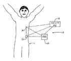
注入媒体送達システム10の一般化された表現が図1に示されており、このシステムは、本明細書で説明されている本発明の一実施形態により構成された送達デバイス12を備える。システム10は、さらに、限定はしないが、センサまたはモニタ14、コマンド制御デバイス(CCD)16、およびコンピュータ18を含む、送達デバイス12と通信するように結合されている他のコンポーネントも備えることができる。CCD16、センサまたはモニタ14、コンピュータ18、および送達デバイス12は、それぞれ、システムの他のコンポーネントとの通信を可能にする受信機、送信機またはトランシーバ電子回路を備えることができる。送達デバイス12は、センサデータを分析し、感知されたデータおよび/または事前にプログラムされた送達ルーチンに従って注入媒体を送達するための電子回路およびソフトウェアを備えることができる。処理、送達ルーチン格納、および制御機能の一部は、CCD16および/またはコンピュータ18により実行できるため、より簡素化された電子回路を使って送達デバイス12を製作できる。しかし、他の実施形態では、システム10は、図1に示されているシステム10の他のコンポーネントのうちの1つ以上がなくても動作する送達デバイス12を備えることができる。これらの種類の通信および/または制御機能、さらには、デバイスの機能セットおよび/またはプログラムオプションの実施例は、本願に引用して援用する、2003年5月27日に出願した「External Infusion Device with Remote Programming, Bolus Estimator and/or Vibration Alarm Capabilities」という表題の米国特許出願第10/445,477号明細書、および2003年5月5日に出願した「Handheld Personal Data Assistant (PDA) with a Medical Device and Method of Using the Same」という表題の10/429,385号明細書、および2001年3月21日に出願した「Control Tabs For Infusion Devices And Methods Of Using The Same」という表題の米国特許出願第09/813,660号明細書で説明されている。
A generalized representation of an infusion
図1の一般化されたシステム図において、送達デバイス12およびセンサまたはモニタ14は、患者利用者1に固定される。図1においてこれらのコンポーネントが患者利用者1に固定される場所は、代表的な、限定しない実施例としてのみ記載されている。送達デバイス12およびセンサまたはモニタ14は、患者利用者1の身体上の他の場所に固定され、またそのような場所は、システム10により施される治療の種類に依存しうる。このような他の場所は、限定はしないが、患者利用者の身体上の他の場所、患者利用者の衣服上のいくつかの場所、ベルト、サスペンダ、ストラップ、財布、トートバッグ、または患者利用者が持ち運ぶことができる他の構造物を含むことができる。
In the generalized system diagram of FIG. 1, the
以下にさらに詳細に説明するように、送達デバイス12は、これに限らないが、インスリン製剤などの注入媒体を制御した方法で患者利用者の身体に送達するように、注入媒体の貯蔵容器およびポンプを含んでいる。送達デバイス12、センサまたはモニタ14、CCD16およびコンピュータ18の間で、制御命令および/またはデータを通信することができる。送達デバイス12は、パッチのように、患者利用者1の皮膚、患者利用者の身体上の所望の場所に固定するように構成されうる。このような実施形態では、送達デバイス12は、快適なように、またデバイスを例えば衣服の下に隠せるように比較的小さな寸法を有するのが望ましい。
As will be described in more detail below, the
パッチ様の送達デバイスの実施例は、本願に引用して援用する、2005年8月23日に出願した米国特許出願第11/211,095号明細書において説明されている。米国特許出願第11/211,095号に記載された送達デバイスは、流体を貯蔵容器から選択的に駆動させる可動プランジャを有する貯蔵容器構造を利用している。本発明の一実施形態により、図4〜7または図8および9に関して図示および記載したようなポンプおよび駆動装置を利用することができる、パッチ様の送達デバイス12の実施例が本明細書図2〜3に示されている。別の送達デバイス実施形態は、図10〜15に関して図示および記載したようなポンプおよび駆動装置を利用することができる。さらに別の送達デバイス実施形態は、図16および17に図示および記載したようなポンプおよび駆動装置を利用することができる。さらに別の送達デバイス実施形態は、図18〜20に関して図示および記載したようなポンプおよび駆動装置を利用することができる。図2の送達デバイス12は、いくつかの実施形態では、1回または複数回の特定の使用後に処分することができるベースハウジング部分20、および別のハウジング部分22を備えている。これに限らないが便宜上、ベースハウジング部分20は、本明細書では使い捨てハウジング部分または使い捨て部分と言い、別のハウジング部分22は、本明細書では耐久ハウジング部分または耐久部分と言う。しかし、上に記したように、動作中、いずれかのまたは両方のハウジング部分20または22は、使用の内容によって、処分するまたは再利用することができる。
Examples of patch-like delivery devices are described in US patent application Ser. No. 11 / 211,095 filed Aug. 23, 2005, which is incorporated herein by reference. The delivery device described in US patent application Ser. No. 11 / 211,095 utilizes a storage container structure having a movable plunger that selectively drives fluid from the storage container. An example of a patch-
使い捨てハウジング部分20は、送達デバイス12の動作時に、患者利用者の皮膚または注入媒体と通常接触する構造要素を支持することができる。他方、耐久ハウジング部分22は、送達デバイス12の動作時に、患者利用者または注入媒体と通常は接触しない要素(電子回路、モータコンポーネント、リンクコンポーネントなど)を支持することができる。したがって、送達デバイス12の耐久ハウジング部分22内の要素は、典型的には、送達デバイス12の通常動作中に、患者利用者または注入媒体との接触から汚染されることはない。
The
例示されている実施形態では、送達デバイス12の使い捨てハウジング部分20は、貯蔵容器およびポンプデバイスを収納する貯蔵容器保持部分24を備える、あるいは支持するベース21を備えている。耐久ハウジング部分22は、貯蔵容器保持部分24に隣接するベース21上に固定されるハウジングを備えることができる。耐久ハウジング部分22は、電動モータ(図2には図示せず)などの適切な駆動デバイス、および耐久ハウジング部分22が使い捨てハウジング部分20に結合されている場合に、貯蔵容器から流体を追い出すように駆動デバイスをポンプに動作可能に結合させる駆動リンクコンポーネント(図2には図示せず)を収納することができる。耐久ハウジング部分22は、さらに、貯蔵容器から流体を制御しつつ送り出すための駆動デバイスの動作を制御するのに好適な制御電子回路(図2に示されていない)も収納することができる。さらに他の実施形態は、限定はしないが、センサまたはモニタ14、CCD16、コンピュータ18、および/または図1に示されているシステム10の他のコンポーネントと通信するための通信電子回路(図2に示されていない)など、耐久ハウジング部分22内の他の電子回路を備えることができる。
In the illustrated embodiment, the
使い捨てハウジング部分20のベース21は、患者利用者の皮膚上の所望の場所に固定するように構成されている底面(下を向きおよび図2および3のページに入る向き)を有する。ベース21を患者利用者の皮膚に接着するために、ベース21の底面と患者利用者の皮膚との間の界面に好適な接着剤を使用することができる。接着剤は、ベース21の底面に施され、剥離可能カバー層23が接着材料を覆う。この方法で、患者利用者は、カバー層23を剥ぎ取って接着材料を露出させ、そうして、ベース21の接着側を患者利用者の皮膚にあてがうことができる。以下に記載する別の実施形態では、多数の再利用または再応用のためにベースを患者利用者の皮膚に固定し、そこから取り除き、その後、再び固定することを可能にするように、カバー層材料の多数の層と交互になった接着材料の多数の層をベース21上に設けることができる。以下にさらに詳細に説明するように、接着材料および剥離可能カバーの多数の交互の層を、患者利用者の皮膚へのベース21の多数の応用および再応用のために利用することができる。
The
使い捨て部分20は、貯蔵容器保持部分24内に配置されている針挿入機構を操作するためのボタンまたは他のオペレータ25を備えることができる。それとは別に、またはそれに加えて、参照番号25は開口部を表しているが、その開口部を通して、外部針挿入機構が動作することができる。適切な針挿入機構の実施例は、それぞれ本願に引用して援用する、2005年8月23日に出願した米国特許出願第11/211,095号、および2006年8月23日に出願した「Infusion Medium Delivery Device,System And Method With Needle Inserter And Needle Inserter Device And Method」という表題の米国特許仮出願第60/839,840号(代理人整理番号047711.0384)に記載されている。針および/またはカニューレを挿入するために、他の針/カニューレ挿入具を使用する(または使用できるように変形する)ことができ、例えば、本願に引用して援用する、2003年3月14日に出願した「Auto Insertion Device For Silhouette Or Similar Products」という表題の米国特許出願第10/389,132号明細書、および/または2002年12月9日に出願した「Insertion Device For Insertion Set and Method of Using the Same」という表題の米国特許出願第10/314,653号明細書を参照のこと。それとは別に、貯蔵容器保持部分は、例えば米国特許出願第11/211,095号の図2を参照しつつ説明されているように、中空管の一方の端部を貯蔵容器に接続するのに好適な開口部またはポートを備えることができ、中空管の他端は、患者利用者の皮膚を刺し通し、注入媒体を貯蔵容器から患者利用者体内に運ぶための中空針に接続される。
The
送達デバイス12の耐久ハウジング部分22は、使い捨てハウジング部分20と嵌合するように、また固定されるように構成されたハウジングシェルを備える。耐久ハウジング部分22および使い捨てハウジング部分20は、対応する形状の溝、刻み目、タブ、または機械技術の分野においてよく知られている方法で2つの部分を手で圧着することにより、2つのパーツを(例えば、摩擦接続、スナップ接続、可撓性または可動連動部材、または他の適切な接続装置によって)容易に接続させるおよび分離することができる他の適切な特徴を備えることができる。同様にして、耐久ハウジング部分22および使い捨て部分20は、手で十分な力を加えてくっついている2つのパーツを引き離すことにより分離されうる。別の実施形態では、環状シールなどの適切なシールを、使い捨てハウジング部分20および/または耐久ハウジング部分22の周辺縁部に沿って配置することにより、使い捨てハウジング部分20と耐久ハウジング部分22の間に液体、密封、または気密封止をすることができる。
The
耐久ハウジング部分22および使い捨てハウジング部分20は、上述のように、その形状を維持し、しかも効果的にかみ合わせ、また引き離せる十分な柔軟性と弾性を有する好適な剛体材料で作ることができる。ベース21の材料について、患者利用者の皮膚との好適な親和性を持つものを選択できる。例えば、送達デバイス12の使い捨てハウジング部分20および耐久ハウジング部分22は、好適なプラスチック、金属、複合材料などで作ることができる。使い捨てハウジング部分20は、耐久ハウジング部分22に比べて同じ種類の材料または異なる材料で作ることができる。使い捨ておよび耐久ハウジング部分は、射出成形または他の成形処理、機械加工、またはこれらの組み合わせにより製造されうる。
The
ベース21は、柔軟なシリコーン、プラスチック、ゴム、合成ゴムなどの比較的柔軟な材料で作ることができる。患者利用者の皮膚に合わせて屈曲できる材料のベース21を形成することにより、ベースが患者利用者の皮膚に固定されたときの患者利用者の快適感のレベルを高めることができる。また、柔軟なベース21を使用すると、ベース21が固定されうる患者利用者の身体の部位の選択範囲が広がる。
The base 21 can be made of a relatively flexible material such as flexible silicone, plastic, rubber, or synthetic rubber. By forming the
使い捨てハウジング部分20および/または耐久ハウジング部分22は、例えば、使い捨てハウジング部分20が患者利用者の皮膚に固定されたときに患者利用者の皮膚を刺し通す針(図2および3に示されていない)を通して、患者利用者に接続する内部センサ(図2および3に示されていない)を備えることができる。そのような実施形態では、好適な開口(図2および3に示されていない)を、ベース21内に形成することができ、これにより、センサ針が伸ばされ患者利用者の皮膚を刺し通すときに、センサ針を通すことができる。別の方法では、送達デバイス12の耐久ハウジング部分20は、2005年8月23日に出願した「Infusion Device And Method With Disposable Portion」という表題の米国特許出願第11/211,095号の図2に関して記載したように、センサリードを通して外部センサ14に接続することができる。センサは、送達デバイス12により施される治療の性質に応じて、好適な生物学的感知デバイスを備えることができる。例えば、インスリンを糖尿病の患者に送達する状況では、センサ14は、血糖センサを備えることができる。それとは別に、またはそれに加えて、1つ以上の環境条件を感知するために、1つ以上の環境感知デバイスを送達デバイス12内に、または送達デバイス12上に備えることができる。さらなる代替実施形態では、センサは、例えば本願に引用して援用する2005年6月8日に出願した「Dual Insertion Set」という表題の米国特許出願第11/149,119号明細書にされているような、注入カニューレおよび/または針の一部として、またはそれと一緒に収めることができる。
The
上述のように、送達デバイス12の使い捨て要素を耐久要素から分離することにより、使い捨て要素は、使い捨て部分20上に配列することができ、耐久要素は、分離可能な耐久部分22内に配列することができる。この点に関して、送達デバイス12を1回(または所定の回数)使用した後、使い捨て部分20を耐久部分22から分離して、使い捨て部分20を適切な方法で処分することができる。次いで、耐久部分22を新しい(未使用の、利用者充填された、事前充填された、再充填された、改装された、または作り直しされた)使い捨て部分20と嵌合させて、さらに患者利用者側で送達操作を行うことができる。これにより、さらに、利用者は、貯蔵容器26を、アミリン、GLP−1、バイエッタ、ペプチドC、インスリン抵抗性改善薬、薬物の組み合わせ(インスリンを含む場合または含まない場合)などの異なる薬物が入っている異なる貯蔵容器に切り替え、交換することにより薬物送達を変更するという選択肢を与えられる。別の方法では、利用者は、異なる種類のインスリン(例えば、持続性、即効性など)を切り替えるか、または異なる濃度(U50、U100、U200、U400など)を使用することができる。
As described above, by separating the disposable element of the
本発明の一実施形態による送達デバイス12の使い捨てハウジング部分20および耐久ハウジング部分22の例が、図4〜7に示されており、図4および5は使い捨てハウジング部分20の上面図および側面図をそれぞれ示しており、図6および7は耐久ハウジング部分22の上断面図および側断面図をそれぞれ示している。図4を参照すると、使い捨てハウジング部分20は、上に記載したように、ベース部分21および貯蔵容器保持部分24を備えている。図4〜7を参照すると、耐久ハウジング部分22は、使い捨てハウジング部分20の貯蔵容器保持部分24に隣接してベース部分21上に手動で位置決めされ、使い捨てハウジング部分20に係合および接続されるが、手動力によって使い捨てハウジング部分20から選択的に分離されるように構成されている。耐久ハウジング部分22が使い捨てハウジング部分20に係合および接続されると、耐久ハウジング部分22内の駆動デバイスは、以下に説明するように、使い捨てハウジング部分20内に置かれたポンプデバイスとの動作可能接続を行うように配置される。
Examples of
貯蔵容器26は、貯蔵容器保持部分24内に配置されている。貯蔵容器26は、これに限らないがインスリン製剤などの流体注入媒体を入れるための内部容積を有する容器を含むことができる。貯蔵容器26は、これに限らないが、適切な金属、プラスチック、セラミック、ガラス、複合材料などを含む、注入媒体と適切に適合するあらゆる材料で作ることができる。例えば、貯蔵容器26は、その内容本願に引用して援用する、2005年4月5日に出願した米国特許出願第11/100,188号(公開第2005/0197626号)に記載されたような、TOPAS(Celanese Corporationの系列会社であるTiconaの登録商標)と呼ばれるプラスチック材料で形成することができる。
The
貯蔵容器26は、使い捨てハウジング部分20の貯蔵容器保持部分24によってあらゆる適切な方法で支持することができる。例えば、貯蔵容器26は、ベース21の表面上に支持し、1つ以上の突起、壁面または他の表面によって定位置に保持することができる。いくつかの実施形態では、貯蔵容器26は取り外し可能であり、使い捨てハウジング部分20と交換可能であるように構成することができる。他の実施形態では、貯蔵容器26は、使い捨てハウジング部分20からの貯蔵容器26の取り外しを抑制することを意図した方法で、使い捨てハウジング部分20に固定することができる。例えば、貯蔵容器26の表面をベース21または使い捨てハウジング部分20の他の構造に接着させるのに接着材料を利用することができる。さらに別の実施形態では、貯蔵容器交換、再充填、または他のサービスのために、貯蔵容器をベースに固定し、そこから取り除き、その後、再び固定する、または別の貯蔵容器と交換してベースに固定することを可能にするように、カバー層材料の多数の層と交互になった接着材料の多数の層を貯蔵容器26またはベース21上に設けることができる。
The
さらに他の実施形態では、貯蔵容器26は、例えば貯蔵容器保持部分24の別の中実部分内に設けられた中空チャンバとして、貯蔵容器保持部分24と一体的に形成することができる。このような実施形態では、貯蔵容器保持部分24の中空内部は、適切な金属、プラスチック、プラスチックTOPAS(Celanese Corporationの系列会社であるTiconaの登録商標)、セラミック、ガラス、複合材料などで別の方法でコーティングされるか、または裏打ちすることができる。それとは別に、またはそれに加えて、保持部分24それ自体は、好適な金属、プラスチック、TOPAS(Celanese Corporationの系列会社であるTiconaの登録商標)、セラミック、ガラス、複合材料などで作ることができる。
In still other embodiments, the
貯蔵容器26は、出口ポート30を有し、これを通して貯蔵容器26の内部に入れられた注入媒体は貯蔵容器から連絡させることができる。出口ポート30は、貯蔵容器26の内部に開口しており、流体導管32を出口ポートと流体流連絡して接続させる適切な管接続構造を備えることができる。接続構造は、貯蔵容器26の内部との流体流連絡を行うように、貯蔵容器26に選択的に(または、いくつかの実施形態では永久的に)接続させることができるあらゆる適切な接続構造を備えることができる。例えば、接続構造は貯蔵容器の出口ポート内に置かれた穿刺可能隔壁で機能することができる。このような実施形態では、接続構造は、貯蔵容器の出口ポートを受けるキャップ構造、および貯蔵容器26の出口ポート内の隔壁を穿孔する中空針を有する典型的なルアータイプコネクタ(これに限らないが、本願に引用して援用する、2006年8月23日に出願した「Infusion Medium Delivery Device,System And Method With Needle Inserter And Needle Inserter Device And Method」という表題の米国特許出願第60/839,840号(代理人整理番号047711.0384)に記載された貯蔵容器コネクタ86)を備えることができる。針/隔壁コネクタの別の実施例は、本願に引用して援用する、2003年12月22に出願した「Reservoir Connector」という表題の米国特許出願第10/328,393号で説明されている。他の代替形態では、ルアーロックなどの非隔壁コネクタを利用することもできる。導管32は、これに限らないが、シリコーンまたは他のプラスチック、金属、セラミックまたは複合材料を含む、これに限らないがあらゆる適切な材料で作られた管状導管などの流体流路を提供するあらゆる適切な構造を含むことができる。
The
導管32の第1の端部は、上に記載したような貯蔵容器接続構造を通して、貯蔵容器に接続される、または接続可能である。導管32の第2の端部は、ポンプデバイス34の入口ポート33と流体流連絡して接続されている。ポンプデバイス34は、使い捨てハウジング部分20上に置かれた送達または注射部位38に流体を運ぶように、第2の導管36に流体流連絡して接続された出口ポート35を有する。注射部位38は、患者利用者への針またはカニューレの挿入、および第2の導管36と流体流連絡した針またはカニューレの接続を助ける挿入機構を備えることができる。送達デバイスに内蔵されたこのような挿入機構の実施例が、全体をそれぞれ本願に引用して援用する、2005年8月23日に出願した「Infusion Device And Method With Disposable Portion」という表題の米国特許出願第11/211,095号、および2006年8月23日に出願した「Infusion Medium Delivery Device,System And Method With Needle Inserter And Needle Inserter Device And Method」という表題の米国特許出願第60/839,840号(代理人整理番号047711.0384)(それぞれ、本発明の譲受人に譲渡されている)に記載されている。例えば、両方とも全体的に本願に引用して援用する、2003年3月14日に出願した「Auto Insertion Device For Silhouette Or Similar Products」という表題の米国特許出願第10/389,132号、および/または2002年12月9日に出願した「Insertion Device For Insertion Set and Method of Using the Same」という表題の米国特許出願第10/314,653号に記載されたような、他の針/カニューレ挿入具を使用(または使用のために変形)して、針および/またはカニューレを挿入することができる。
The first end of the
第1の弁40は、貯蔵容器26からポンプデバイス34の入口ポート33までの一方向への流体流を制約するために、第1の導管32内に(または、第1の導管32と貯蔵容器26またはポンプデバイス34の入口ポート33の間に)設けることができる。第2の弁42は、ポンプデバイス34の出口ポート35から注射部位38までの一方向への流体流を制約するために、第2の導管36内に(または、第2の導管36と注射部位38またはポンプデバイス34の出口ポート35の間に)設けることができる。あらゆる適切な一方向弁構造を、弁40および42に利用することができる。
The
図4のポンプデバイス34の例示的な実施形態は、内部容積45を有するポンプチャンバ44と、ポンプチャンバ44内に置かれたピストンヘッド46を有する可動ピストンと、ピストンヘッドから延びるピストンシャフト50とを備えている。ピストンヘッド46は、ピストンヘッド46の出口ポート側でチャンバ44の部分の容積を小さくするように、引き込み位置(図4に示す)から矢印48の方向に向かって動作位置まで選択的に可動である。ピストンヘッド46はまた、ピストンヘッド46の出口ポート側でチャンバ44の部分の容積を大きくするように、動作位置から矢印48と反対の方向に向かって引き込み位置(図4に示す)まで可動である。
The exemplary embodiment of the
ピストンヘッド46は、ピストンシャフト50に固定接続されている。ピストンシャフト50は、ピストン46の直線移動方向(矢印48のおよびそれと反対の直線方向)に沿って延びる長手方向軸Aを画定し、ピストンヘッドに接続された第1の端部を有する。ピストンヘッド46およびピストンシャフト50は、一体型本体を備えることができる。別の方法では、ピストンヘッド46およびピストンシャフト50は、互いに固定関係で結合された2つの部材を備えることができる。ピストンシャフト50の第2の端部は、押し板52に固定接続されている。押し板52およびピストンシャフト50は、一体的本体を備えることができる。別の方法では、押し板52およびピストンシャフト50は、互いに固定関係で結合された2つの部材を備えることができる。ピストンヘッド46、ピストンシャフト50および押し板52は、これに限らないが、金属、プラスチック、セラミック、複合材料などを含むあらゆる適切な1つ以上の剛性材料で作ることができる。
The
押し板52は、ピストンチャンバ44から離れているが、溝路部56によってピストンチャンバ44に接続された第2のチャンバ54内に配置することができる。溝路部56は、ピストンシャフト50がこれを通して延びる内部通路を有する中空管状構造を備えることができる。流体が溝路部56を通過するのを抑制するように、これを限らないが1つ以上のOリングシールなどの1つ以上のシール58を溝路部56の内部通路内にまたはこれに隣接して配置することができる。(1つ以上の)シール58は、これに限らないが、プラスチック、ゴム、シリコーン、金属、セラミックまたは複合材料を含むあらゆる適切なシール材料で作ることができる。
The
バイアス部材60は、バイアス力をピストンに与えて、矢印48の方向と反対の軸Aの直線寸法に沿ってピストンを押し込むように、例えば押し板52との動作可能接続によってピストンに動作可能に接続される。図4の実施形態では、バイアス部材60は、ピストンシャフト50の長手方向軸Aの周りでこれと同軸で、第2のチャンバ54内に配置されたコイルばねを備えている。図4のコイルばねバイアス部材60は、第2のチャンバ54の内壁に当接する一端部と、押し板52の第1の表面に当接する第2の端部とを有する。コイルばねバイアス部材60は、力を押し板52に矢印48の方向と反対の方向に加えるように、部分圧縮状態になるように構成されている。押し板52の第1の表面は、コイルばねバイアス部材60を定位置に保持するのを助けるように、コイルばねバイアス部材60の一端部がある管状溝を備えることができる。同様の管状溝は、コイルばねバイアス部材によって当接される第2のチャンバ54の内壁の表面に設けることができ、その中にコイルばねバイアス部材のもう一端部がある。
一実施形態では、ポンプチャンバ44および第2のチャンバ54はそれぞれ、中空内部を有するほぼ円筒形本体を備えている。このような一実施形態では、溝路部56は、ポンプチャンバ44と第2のチャンバ54の間に延び、ほぼ円筒形の内部容積を有するほぼ中空円筒形部を備えることができる。またこのような実施形態では、ピストンヘッド46および押し板52はそれぞれ、ディスク形部材を備えることができ、ピストンシャフト50は円筒形部材を備えることができ、それぞれ(軸Aと垂直の)ほぼ円形断面を有することができる。しかし、他の実施形態では、他の適切な形状を有するこのような構造要素を利用することができる。ポンプチャンバ44、第2のチャンバ54、および溝路部56は単一の一体型構造を備えることができる。代替実施形態では、ポンプチャンバ44、第2のチャンバ54、および溝路部56は、互いに固定関係で接続された1つ以上の別個の部分で構成することができる。ポンプチャンバ44、第2のチャンバ54、および溝路部56は、これに限らないが、金属、プラスチック、セラミック、複合材料などを含む、あらゆる適切な1つ以上の剛性材料で作ることができる。一実施形態では、第2のチャンバ54は、使い捨てハウジング部分20の貯蔵容器保持部分24を形成するハウジング構造と一体的に構成することができる。貯蔵容器保持部分24のハウジング構造は、注射部位での針インジェクタの操作の前に、ハウジング構造の壁面、シール58、および送達部材38での隔壁または他のシール構造によって外部環境から封止された(貯蔵容器26、導管32および36、注射部位38のコンポーネント、およびポンプデバイス34のコンポーネントを入れる)内部容積を画定することができる。
In one embodiment, pump
使い捨てハウジング部分20の貯蔵容器保持部分24は、押し板52がこれを通して作用することができる、開口部(陥凹部であってもよい)68を有する側部または壁面66を有する。例えば、(コイルばねバイアス部材60が当接する第1の表面の面する方向に対して反対の方向と向かい合った)押し板52の第2の表面は、開口部68を通して露出させることができ、開口部68から外向きの方向と向かい合う。押し板は、以下に説明するように、耐久ハウジング部分22および使い捨てハウジング部分20が動作のために互いに係合および接続されている場合、耐久ハウジング部分22上に支持された駆動リンクの一部によって係合される(またはこれに作用する)ように配置されている。
The storage
耐久ハウジング部分22は、図2に示すように耐久ハウジング部分22が使い捨てハウジング部分20と係合している場合、使い捨てハウジング部分20の貯蔵容器保持部分24の壁面66と向かい合った側部または壁面70(図6)を有する。側部または壁面70は開口部72を画定し、これを通してリンク構造の一部が延び、耐久ハウジング部分22が使い捨てハウジング部分20と係合している場合、押し板52に接触し、およびこれに作用する。
The
上に記載するように、耐久ハウジング部分22は、使い捨てハウジング部分20に係合および接続するが、十分な手動力を加えることによって、使い捨てハウジング部分20から切断および分離されるように構成されている。これに限らないが係合可能なスナップ嵌合部材、摩擦嵌合部材、可撓性または可動連結部材などを含むあらゆる適切な接続構造を、使い捨てハウジング部分および耐久ハウジング部分上で利用することができる。図4〜6に示す実施形態では、接続構造は、使い捨てハウジング部分20の貯蔵容器保持部分24の壁面66から延びる1対の係合爪74と、耐久ハウジング部分22の壁面70上の1対の対応する形状の受け入れ部76とを備えている。各係合爪74は、耐久ハウジング部分22が係合位置で使い捨てハウジング部分20と位置合わせされて、耐久ハウジング部分22および使い捨てハウジング部分20を互いに接続する場合に、受け入れ部76の関連するものと嵌合するように構成されている。
As described above, the
各係合爪74は、壁面66から延び、係合爪74がその関連する受け入れ部76に挿入される場合に、受け入れ部76の対応する停止表面79と係合する停止表面78を有する構造を備えることができる。停止表面78および79は係合している場合、十分な分離力が加えられない限り、耐久ハウジング部分22および使い捨てハウジング部分20の分離を抑制する。望ましくは、爪74および/または受け入れ部76の相対可撓性および弾力性により、十分な手動力が分離方向に加えられない限り(例えば、使い捨てハウジング部分が耐久ハウジング部分に対して矢印48の方向に押される、および/または耐久ハウジング部分が使い捨てハウジング部分に対して矢印48と反対の方向に押されない限り)、耐久ハウジング部分22および使い捨てハウジング部分20を互いに接続したままにすることが可能になる。十分な力により、各爪74の停止表面78がその関連する受け入れ部の停止表面79の上に乗り上げ、したがって使い捨てハウジング部分20が耐久ハウジング部分22から分離されるときに、爪74を受け入れ部76から引き出すことを可能にするのに十分なように、爪74および/または受け入れ部76を弾力性屈曲される。
Each
各爪74は、受け入れ部76内への爪74の挿入を容易にする角度付きまたは湾曲表面(ある角度での、または壁面66の外部表面と平行または垂直ではない接線を有する表面)を備えることができる。爪74は、これに限らないが、金属、プラスチック、複合材料などを含む、本明細書に記載したように働くのに十分な剛性および可撓性を有する材料で作ることができる。爪74は、使い捨てハウジング部分20の壁面66と同じ材料で作ることができ、これと一体的に形成することができる。他の実施形態では、爪74は使い捨てハウジング部分とは別に形成し、その後壁面66に接続させることができる。図示した実施形態は、1対の爪74および対応する1対の受け入れ部76を示しているが、他の実施形態は単一の爪および関連する受け入れ部、または3つ以上の爪および関連する受け入れ部を利用することができる。また、図示した実施形態は、使い捨てハウジング部分20の壁面66の爪74、および耐久ハウジング部分22の壁面70の受け入れ部76を示しているが、他の実施形態は、耐久ハウジング部分22の壁面70の1つ以上の爪および使い捨てハウジング部分20の壁面66の1つ以上の関連する受け入れ部を利用することができる。さらに他の実施形態は、各壁面66および70の1つ以上の爪および関連する受け入れ部のさまざまな組み合わせを利用することができる。
Each
耐久ハウジング部分22は、内部容積80を有するハウジング構造を備えている。駆動デバイス82は、耐久ハウジング部分22の内部容積に支持され、リンク構造86を通して駆動シャフト84に動作可能に接続されている。駆動デバイス82は、例えばこれに限らないが、電力を回転動作に変換するモータまたは他のデバイスを備えることができる。このような駆動デバイスは、これに限らないが、DCモータ、フラットまたはパンケーキDCモータ、サーボモータ、ステッパモータ、電子整流モータ、回転圧電作動モータ、雁木車を備えたまたは備えていない圧電作動または熱作動ベンダ、雁木車を備えたまたは備えていない電子作動ソレノイド、または雁木車を備えたまたは備えていない形状記憶合金ワイヤを含むことができる。ベンダ、ソレノイド、形状記憶合金ワイヤなどを備えた雁木車装置のさまざまな実施例が、本願に引用して援用する、2006年8月23日に出願した「Infusion Medium Delivery Device And Method For Driving Plunger In Reservoir」という表題の米国特許出願第60/839,822号(代理人整理番号047711.0382)に記載されている。形状記憶合金ワイヤ駆動システムの別の実施例は、両方とも本願に引用して援用する、2002年4月23日発行された「Incremental Motion Pump Mechanisms Driven by Shape Memory Alloy Wire or the Like」という表題の米国特許第6,375,638号、および2005年9月19日に出願した「SMA Wire Driven Positive Displacement MicroPump With Pulsatile Output」という表題の米国特許出願第11/230,142号で説明されている。
The
リンク構造86は、あらゆる適切なギア、歯車列、ベルト、シャフトまたはモータまたは他の回転動作生成デバイスの回転動作を駆動シャフト84の直線動作に伝達させる他のリンク装置を備えることができる。図6の実施形態では、リンク構造は、回転軸94周りで駆動ギア92で回転するように結合された駆動カム90を備えている。駆動シャフト84は、回転軸94からずれた位置で駆動カムに結合された一端部を有し、それによって駆動カムの回転は駆動シャフト84の直線動作につながる。駆動ギア92は、例えば、モータまたは他の回転駆動デバイスへの直接接続によって、またはこれに限らないが、ギア、シャフト、ベルトなどのリンク構造86の他の部分を通した間接的接続によって、モータまたは他の回転駆動デバイスによって軸94周りで回転駆動されるように配置されている。リンク構造の別の実施例は、本願に引用して援用する、2001年3月21日出願の「Control Tabs For Infusion Devices And Methods Of Using The Same」という表題の米国特許出願第09/813,660号で説明されている。
The
他の実施形態では、駆動デバイス82は、これに限らないが、圧電作動ソレノイドまたはベンダ、熱作動ソレノイドまたはベンダ、および電動ソレノイドデバイスを含む、電力を直線動作に変換するデバイスを備えることができる。このような直線動作駆動デバイス実施形態では、リンク構造86は、あらゆる適切なギア、歯車列、ベルト、シャフトまたはモータまたは駆動デバイスの直線動作を駆動シャフト84の直線動作に伝達させる他のリンク装置を備えることができる。別の直線動作駆動デバイス実施形態では、直線動作駆動デバイスは、駆動シャフト84に直接接続させることができる(または、駆動シャフト84はソレノイドの駆動シャフトなどの、直線動作駆動デバイスの一部であってもよい)。
In other embodiments, the
駆動デバイス82は、所望の注入送達プログラムまたはプロファイルにより駆動デバイスの操作を制御するように、送達デバイスの耐久ハウジング部分22内で支持される制御回路に接続されている。送達プログラムまたはプロファイルは、耐久ハウジング部分22内に置かれた適切な電子記憶媒体(図示せず)内に記憶させることができる、および/またはCCD16またはコンピュータ18(図1に示す)などの他のソースから送達デバイス12に伝達させることができる。このような実施形態では、送達プログラムまたはプロファイルは、送達プログラムまたはプロファイルにより駆動デバイス82の操作を制御する制御回路によって利用することができる。別の方法では、またはこれに加えて、制御回路は、デバイス12内で発生された、またはCCD16またはコンピュータ18(図1に示す)などの他のソースからデバイス12に伝達される送達要求制御信号に応答して、注入媒体の1つ以上の個別容量を送達するように駆動デバイス82を制御することができる。
The
耐久ハウジング部分22は、センサデータまたは他のデータの格納のため、処理および制御機能のため、または他の機能のために、CCD16またはコンピュータ18などの外部デバイスと通信する追加電子回路(図示せず)を備えることができる。耐久ハウジング部分22は、1つ以上のボタン、電子ディスプレイなどを備えるユーザーインターフェイス(図示せず)、および関連する電子インターフェイス回路を有し、これにより、利用者は、データにアクセスし、および/またはデータもしくは命令を耐久ハウジング部分22内の制御電子回路に入力することができる。このようなタイプの通信および/または制御能力と、デバイス機能セットおよび/またはプログラムオプションの実施例が、両方とも本願に引用して援用する、2003年5月27日に出願した「External Infusion Device with Remote Programming, Bolus Estimator and/or Vibration Alarm Capabilities」という表題の米国特許出願第10/445,477号、および2003年5月5日に出願した「Handheld Personal Data Assistant(PDA) with a Medical Device and Method of Using the Same」という表題の米国特許出願第10/429,385号に記載されている。
耐久ハウジング部分22は、電池、高エネルギーキャパシタまたは他の電子回路用電源を収納しており、これにより、駆動デバイス82、制御回路電子部品、および耐久ハウジング部分22に収められている他の電子回路に電力を供給することができる。制御回路電子部品、他の電子回路、および電源は、図6および7に参照番号98で示されている。このような実施形態では、電池、高エネルギーキャパシタまたは他の電子回路用電源は、耐久ハウジング部分22に設けられた再充電コネクタ(図示せず)を通じて再充電可能であるものとしてよい。別の方法では、またはこれに加えて、電源は取り外し可能であり、耐久ハウジング部分22に対して交換可能である。他の実施形態では、電池、キャパシタまたは他の電子回路用電源(図示せず)は、使い捨てハウジング部分20上で支持され、追加の手動による操作を行わなくても、使い捨てハウジング部分20に耐久ハウジング部分22が結合された際、電気的接続を行う電気コネクタ(図4〜7には図示せず)を通じて、駆動デバイス82、制御回路、および耐久ハウジング部分の他の電子回路に接続可能である。このような電気コネクタは、1つ以上の対の導電性パッドを備えることができ、パッドの各対は、電源の反対極に接続され、耐久ハウジング部分22が使い捨てハウジング部分20と係合している場合、耐久ハウジング部分22上の対応する表面と係合する使い捨てハウジング部分20のあらゆる適切な表面上に配置される。このような実施形態では、耐久ハウジング部分22の対応する表面は、耐久ハウジング部分22が使い捨てハウジング部分20と係合している場合に、駆動デバイス82、制御回路、および耐久ハウジング部分内の他の電子回路に電気的に接続され、使い捨てハウジング部分上の導電性パッドと係合するように配置された1つ以上の対応する対の導電性パッドを備えている。
The
上記の駆動デバイス82、リンク構造86、制御回路、他の電子回路、および電源98は、耐久ハウジング部分22の内部容積80内に置かれている。上に記載したように、駆動シャフト84は、耐久ハウジング部分22の壁面70の開口部を通して延びている。特定の環境条件(限定はしないが、水分、空気、生物学的または医学的流体など)から電気的および機械的コンポーネントを保護するために、耐久部分22を形成するハウジング構造によって、および壁面70の開口部内でまたはこれに隣接して駆動シャフト84の周りに設けられた1つ以上のシール99によって、外部環境から耐久部分22の内部容積80を適切に封止することができる。(1つ以上の)シール99としては、これに限らないが、1つ以上のOリングシールなどを挙げることができる。(1つ以上の)シール99は、これに限らないが、プラスチック、ゴム、シリコーン、金属、セラミックまたは複合材料を含むあらゆる適切なシール材料で作ることができる。
The
したがって、図4〜6の送達デバイス12は、貯蔵容器26、ポンプデバイス34および上記の他のコンポーネントを支持する使い捨てハウジング部分20と、駆動デバイス82、駆動シャフト84、リンク構造86、および電子部品(電源を含むこともできる)98を支持する耐久ハウジング部分22とを備えている。送達デバイス12を操作するためには、使い捨てハウジング部分20内の貯蔵容器を適切な注入媒体で充填することができる。使い捨てハウジング部分20は、上に記載した方法で、患者利用者の皮膚に(貯蔵容器を充填する前または後のいずれかに)固定することができる。針インジェクタは、中空針またはカニューレを患者利用者の皮膚を通して置き、中空針またはカニューレを導管36と流体流連絡して接続させるように操作することができる。
Accordingly, the
耐久ハウジング部分22は、上に記載した方法で、使い捨てハウジング部分20と手動で位置合わせし、(使い捨てハウジング部分が患者利用者の皮膚に固定された前または後のいずれか、および針インジェクタが作動された前または後に)使い捨てハウジング部分20に係合および接続させることができる。耐久ハウジング部分22を使い捨てハウジング部分20と係合および接続させることによって、(駆動カム90に接続された端部と反対側の)駆動シャフト84の端部は、押し板52に当接する、またはこれに隣接して位置決めされる。例えば、耐久ハウジング部分22が使い捨てハウジング部分20と係合および接続されるように位置合わせされる場合、駆動シャフト84は使い捨てハウジング部分20の貯蔵容器保持部分24の壁面66の開口部内に延び、押し板52の外側と向かい合った表面に接触するまたはこれに隣接してあることができる。
The
使い捨てハウジング部分20および耐久ハウジング部分22が互いに係合および接続されると、駆動デバイス82は、上に記載するように、駆動シャフト84を(矢印48の方向および矢印48の方向と反対の方向に対応する)2つのほぼ直線方向に沿って前後動作で選択的に移動させるように、制御回路電子部品および電源98によって与えられる電気制御および電力で選択的に作動させることができる。例えば、駆動デバイス82は、駆動ギア92および駆動カム90を回転軸94周りに第1の方向に選択的に回転させるように制御することができる。駆動カム90が回転すると、駆動シャフトは矢印48の直線寸法に沿って、一方向に、その後反対方向に移動される。別の方法では、駆動シャフト82は、駆動ギア92および駆動カム90を一方向に、その後反対方向に回転させることによって、例えば、駆動デバイスを一方向に、その後反対方向に駆動するように制御することによって直線前後動作で駆動させることができる。
When the
駆動シャフト84が矢印48の方向に駆動されると、駆動シャフト84の伸展端部は押し板52と係合し、コイルばねバイアス部材60の力に対して、押し板52を矢印48の方向に移動させるのに十分な力を押し板52に矢印48の方向に加える。押し板52が矢印48の方向に駆動されると、ピストンシャフト50およびピストンヘッド46は、引き込み位置(図4に示す)から動作位置まで矢印48の方向に移動される。ピストンヘッド46が動作位置に向かって移動すると、ピストンヘッド46の一方側(図4に示す方向のピストンヘッド46の左に対する側)に置かれたピストンチャンバ44の部分の容積が小さくなる。ピストンチャンバ44容積のその部分が小さくなると、その容積内の圧力が増加して、流体を出口ポート35、導管36および一方向弁42を通して注射部位38まで押し込む。
When the
矢印48の方向の駆動シャフト84の動作量は、引き込み位置(図4に示す)からピストンヘッドを移動させるように選択される。ピストンヘッド46がその動作位置に到達すると、駆動シャフト84も矢印48の方向のその最も遠い動作点に到達する。その後、駆動デバイス82が駆動力を加え続けると、駆動シャフト84は矢印48の方向と反対の方向に移動される。駆動シャフト84が矢印48の方向と反対の方向に移動すると、押し板52、ピストン、ピストンシャフト50およびピストンヘッド46も、コイルばねバイアス部材60の力によって、引き込み位置(図4に示す)まで矢印48の方向と反対の方向に移動する。
The amount of movement of
ピストンヘッド46がその動作位置からその引き込み位置に向けて矢印48の方向と反対の方向に移動すると、ピストンヘッド46の一方側(図4に示す方向のピストンヘッド46の左に対する側)に置かれたピストンチャンバ44の部分の容積が増加する。ピストンチャンバ44容積のその部分が増加すると、その容積内の圧力は、流体を貯蔵容器26から導管32、一方向弁40および入口ポート33を通したピストンチャンバ44の容積のその部分内に引くように十分に小さくなる。このように、ピストンヘッド46の一方側(図4に示す方向のピストンヘッド46の左に対する側)のピストンチャンバの容積の部分は、矢印48の方向のピストンヘッド46の別のストロークのために、注入媒体で充填する。したがって、注入媒体をピストンチャンバ44から注射部位38まで効果的に押し込むように、駆動シャフト84の動作によって、および注入媒体を貯蔵容器26からピストンチャンバ44内に引くように、バイアス部材60の戻り力によってポンプデバイス34を駆動させることができる。適切な量の注入媒体を注射部位を通して患者利用者に選択的に送達するように、予め定められた送達プロファイルにしたがって、駆動デバイス82を制御回路によって制御することができる。送達プロファイルは、引き込み位置から動作位置までのピストンヘッド46の各ストロークのために、ピストンチャンバ44の予め知られている容積、および出口ポート35および導管36を通して注射部位38に送達される注入媒体の予め知られている容量により設計することができる。
When the
ポンプ過程を始める前に、例えば製造組立中にピストンチャンバ44を予め注入媒体で充填することによって、または送達デバイスの使い捨て部分を患者利用者の皮膚に固定する前の別の期間に、充填ポート(図示せず)を通して患者利用者に固定する前または後のいずれかにピストンチャンバ44を充填することによって、またはピストンヘッド46が1つ以上のストロークを行って、注射部位38での針インジェクタの作動の前に流体を貯蔵容器から入口ポート33を通して引くのに十分なようにピストンチャンバ内の圧力を下げるように駆動デバイスを操作することによって、ピストンチャンバ44をプライミングすることができる。さらに他の実施形態では、プライミングポートをピストンチャンバ44内に設けることができ、プライミングポートは空気が逃げるのを可能にするが、注入媒体がピストンチャンバ44から逃げるのを抑制し、空気がピストンチャンバ44内に入るのを抑制する一方向空気弁(図示せず)を備えることができる。このような実施形態では、プライミングポートは、空気の通過を可能にするが、水または他の液体の通過を抑制する材料で覆うことができる。空気流を認めるが、流体を抑制する構造の実施例は、両方とも本願に引用して援用する、2003年12月22日に出願した「Reservoir Connector」という表題の米国特許出願第10/328,393号、および2003年10月31日に出願した「External Infusion Device with a Vented Housing」という表題の米国特許出願第10/699,429号で説明されている。
Before beginning the pumping process, for example, by prefilling the
図4〜6に示す実施形態は、押し板52を引き込み位置(図4に示す)に戻すように力を押し板52に加えるバイアス部材60を利用する。このような一実施形態では、駆動シャフト84は、押し板52と係合および当接して押し板52を矢印48の方向に押すように配置することができ、バイアス部材60は駆動シャフト84が戻り位置に駆動された場合に、押し板52を引き込み位置に向かって(矢印48の方向と反対の方向に)押し戻す。他の実施形態は、押し板52を引き込み位置に戻すように、(矢印48の方向と反対の方向の)駆動シャフト84の戻り動作を利用することができる。このような実施形態は、耐久ハウジング部分22が使い捨てハウジング部分20と係合および接続されている場合に、駆動シャフト84を押し板52と選択的に係合および接続させることを可能にする適切な接続構造を利用することができる。このような接続構造は、これに限らないが、係合可能なスナップ嵌合部材、摩擦嵌合部材、可撓性または可動連結部材などを含むことができる。一実施形態では、駆動シャフト84を押し板52に接続させる接続構造は、(上に記載した爪74および受け入れ部76と同様の)爪および関連する受け入れ部配列を含むことができ、爪および受け入れ部の一方が押し板上に設けられ、爪および受け入れ部のもう一方が駆動シャフト84の端部に設けられている。
The embodiment shown in FIGS. 4-6 utilizes a biasing
上に記載したように、図4〜6に示す実施形態は、これに限らないが、DCモータ、フラットまたはパンケーキDCモータ、サーボモータ、ステッパモータ、電子整流モータ、回転圧電作動モータ、雁木車を備えたまたは備えていない圧電作動または熱作動ベンダ、雁木車を備えたまたは備えていない電子作動ソレノイド、または雁木車を備えたまたは備えていない形状記憶合金(SMA)ワイヤを含むさまざまなタイプの適切な駆動デバイスのいずれか1つを利用することができる。例えば、押し板52の直線動作は、これに限らないが、ニチノール(ニッケルチタン/Naval Ordinance Laboratory)などのSMAワイヤによって行うことができる。ニチノールドライバは、耐久ハウジング部分22または使い捨てハウジング部分20内に設けることができる。
As described above, the embodiments shown in FIGS. 4-6 are not limited to this, but include DC motors, flat or pancake DC motors, servo motors, stepper motors, electronic rectifier motors, rotary piezoelectric actuator motors, and wooden cars. Various types including piezoelectric actuated or thermally actuated vendors with or without, electronically actuated solenoids with or without a wheelbarrow, or shape memory alloy (SMA) wires with or without a wheelbarrow Any one of suitable drive devices can be utilized. For example, the linear motion of the
例えば、図8の実施形態では、SMAワイヤ91は使い捨てハウジング部分20内に置かれ、押し板52に(または、押し板52を取り除くことによってピストンシャフト50に直接)接続された一端部91a、および使い捨てハウジング部分に対して固定位置で接続された第2の端部91bを有する。SMAワイヤ91は、SMAワイヤにわたって適切な電位を加える際に、ピストンシャフト50を矢印48の方向に押すように、直線方向(ワイヤの方向)に拡張するように構成されている。SMAワイヤ91の2つの端部91aおよび91bは、適切な導線95および97を通して、使い捨てハウジング部分20上の電気コネクタ要素93に接続される。
For example, in the embodiment of FIG. 8, the
コネクタ要素93は、使い捨てハウジング部分20および耐久ハウジング部分22が係合している場合に、耐久ハウジング部分22上の対応するコネクタ要素93’と電気的に接続するように構成されている。コネクタ要素93’は、使い捨てハウジング部分20および耐久ハウジング部分22が係合している場合に、導線95および97にわたって電位を選択的に与えて、SMAワイヤを選択的に付勢するように、電池(または、他の適切な電力源)および制御電子部品98に電気的に接続されている。耐久ハウジング部分22内の電源、および使い捨てハウジング部分20内のSMAワイヤ駆動デバイスが動作のために電気的接続のみを必要としているので、それぞれのハウジング部分20および22を囲み封止することができ、外部環境に対するいかなる開口部も含んでいる必要がない。別の実施形態では、このような封止されたハウジング部分は、ハウジング部分の内部と外部環境の間の圧力を均一にする通気開口部を備えることができる。
The connector element 93 is configured to electrically connect with a corresponding connector element 93 ′ on the
図8の実施形態では、耐久ハウジング部分22が使い捨てハウジング部分20と係合している場合、電池および制御電子部品98をSMAワイヤ用導線95および97に接続させるために、コネクタ要素93と93’の間で電気的接続が行われる。電池および制御電子部品98から導線95および97に制御電力信号を加えることにより、SMAワイヤが直線方向に拡張される。SMAワイヤの端部91bは、使い捨てハウジング部分20に固定関係で接続されているので、SMAワイヤの制御直線拡張により、SMAワイヤの第2の端部が矢印48の方向に選択的に移動されて、押し板52を矢印48の方向に移動させる。このようにして、流体をポンプデバイスから注射部位まで選択的に駆動するように、電池および制御電子部品98がポンプデバイス34を操作することができる。
In the embodiment of FIG. 8, when
SMAワイヤを利用する別の駆動実施例が図9に示されており、SMAワイヤは耐久ハウジング部分22内に置かれている。図9では、SMAワイヤ91’は、プッシュロッド100に結合された一端部91a’、および耐久ハウジング部分22に固定関係で結合された第2の端部91b’を有する。プッシュロッド100は、例えば、プッシュロッド100に当接するスライド軸受表面を備えた適切な支持構造102によって、直線方向(矢印48の方向および矢印48と反対の方向)への移動のために支持されている。支持構造102は、耐久ハウジング部分22の一部であってもよい、またはこれに固定することができる。プッシュロッド100は、耐久ハウジング部分22の外側からアクセス可能な嵌合表面を有する嵌合部材104に接続されている。バイアス部材は、嵌合部材104に戻り力を与え、嵌合部材104と支持構造102の間に接続されたばねコイルを備えることができる。
Another drive embodiment utilizing SMA wire is shown in FIG. 9 where the SMA wire is placed within the
嵌合部材104は、耐久ハウジング部分22の外部に置くことができ、および/または耐久ハウジング部分22の開口部を通して延びることができ、それによって耐久ハウジング部分22および使い捨てハウジング部分20が係合している場合に、嵌合部材104の嵌合表面はポンプデバイス34上の対応する嵌合表面と係合するように配置されている。図9の実施形態では、接続シャフト50’はポンプデバイス34から延びており、嵌合部材104の嵌合表面と係合および嵌合するように成形された一端部に嵌合表面を有する。図9の実施形態では、接続シャフト50’は押し板52から延びている。他の実施形態では、押し板52を取り除くことができ、それによって接続シャフト50’はピストンシャフト50の一部を含む。
The
図9の実施形態では、耐久ハウジング部分22および使い捨てハウジング部分20が係合している場合、嵌合部材104とピストンシャフト50の間で機械的接続が行われる。SMAワイヤにわたって制御電力信号を加えることにより、SMAワイヤが直線方向に拡張される。SMAワイヤの端部91b’は、耐久ハウジング部分22に固定関係で接続されているので、SMAワイヤの制御直線拡張により、SMAワイヤの第2の端部が矢印48の方向に選択的に移動されて、プッシュロッド100および嵌合部材104を矢印48の方向に移動させる。このようにして、流体をポンプから注射部位まで選択的に駆動するように、電池および制御電子部品98がポンプデバイス34を操作することができる。
In the embodiment of FIG. 9, a mechanical connection is made between the
本発明の別の実施形態による直線運動ポンプデバイス134が、図10〜15に示されている。ポンプデバイス134は、上に記載した直線運動ポンプデバイス34の代わりに、図4〜7に関して上に記載したように送達デバイス12内で利用することができる。ポンプデバイス134は、直線力を加えてピストンシャトルの直線運動を行うことによって操作されるシャトル機構を備えている。
A linear motion pump device 134 according to another embodiment of the present invention is shown in FIGS. The pump device 134 can be utilized in the
図10を参照すると、ポンプデバイス134は貯蔵容器126から流体を分配するように動作する。貯蔵容器126は、上に記載した使い捨てハウジング部分20と同様の使い捨てハウジング部分内に置くことができる。貯蔵容器126は、図4〜7の貯蔵容器26に関して上に記載したような貯蔵容器構造を備えることができる。別の方法では、貯蔵容器126は、流体が貯蔵容器内部から引き出されるときに、崩壊する可撓性壁面を有する可撓性袋または容器を含むことができる。
Referring to FIG. 10, the pump device 134 operates to dispense fluid from the
貯蔵容器126は、貯蔵容器の充填または再充填のために針(例えば、注射器針)によって穿刺することができる、自己封止隔壁などの隔壁128を備えることができる。隔壁128は、使い捨てハウジング部分20の外側からの充填または再充填動作のためのアクセスを可能にするように、使い捨てハウジング部分20を形成するハウジング構造内の開口部を通して露出される場所に位置決めすることができる。貯蔵容器126は、例えば、注射器の針を隔壁128を通して挿入し、注入媒体を針から貯蔵容器の内部に分配させるように注射器を操作することによって充填または再充填させることができる。
The
ポンプデバイス134は、シャトルハウジング136およびシャトルピストン138を備えている。シャトルハウジング136は、これに限らないが、金属、プラスチック、セラミック、ガラスまたは複合材料を含むあらゆる適切な剛性材料で作られた構造体を備えている。シャトルハウジング136は、長手方向軸A1を有する内部溝路140を備えている。シャトルハウジング136は、外周壁表面137を有する円筒形本体を備えることができ、溝路140は円筒形本体内のほぼ中心に置かれた円筒形溝路であってもよい。しかし、他の実施形態は、シャトルハウジング136および溝路140に対する他の適切な形状を利用することができる。シャトルハウジング136は、シャトルハウジング136の外壁を通して溝路140までの開口部を備えた入口ポート142を備えている。シャトルハウジング136はまた、シャトルハウジング136の外壁を通した溝路140までの第2の開口部を備えた出口ポート144を備えている。出口ポート144は、溝路140の長手方向軸A1に沿って、入口ポート142に対して間隔をおいて配置されている。
The pump device 134 includes a
図10〜15の実施形態では、入口ポート142および出口ポート144は、溝路140の長手方向軸A1の周りで180度だけ互いにずれており、入口ポート142は図10〜15の方向に対して上向きであり、出口ポートは下向きである。しかし、他の実施形態では、入口ポート142および出口ポート144は、180度より小さくまたは大きく互いにずれていてもよい、または溝路140の長手方向軸A1と一列であってもよい(ずれていなくてもよい)。出口ポート144は、図4に示すように、導管36および注射部位38など注射部位と流体流連絡して導管に接続させることができる。
In the embodiment of FIGS. 10-15, the
ピストン138は、それぞれ第1および第2のピストン部146および148を備えている。各ピストン部分146、148は、長手方向軸を有する構造体、および溝路140の形状に対応する形状を備えている。したがって、溝路140が円筒形状を有する実施形態では、ピストン部分146および148の構造体はそれぞれ、溝路140の直径より僅かに小さい外径を有する円筒形本体を備えている。ピストン部分146、148および溝路140の直径は、ピストン部分146、148が溝路140に嵌合し、その中で軸方向に移動することを可能にするが、ピストン部分146、148と溝路140の内壁の間の注入流体の漏洩を抑制するように選択されている。ピストン部分146、148は、これに限らないが、金属、プラスチック、セラミック、ガラスまたは複合材料を含む、あらゆる適切な剛性材料で作ることができる。
The
ピストン部分146、148は、溝路140内に少なくとも部分的に端部から端部まで配置されており、それによってピストン部分146の一端部147はピストン部分148の反対を向いている端部149に向かい合っている。ピストン部分146、148は、互いに結合されているが、溝路140の軸寸法で互いに対して移動可能な別個の構造体である。ピストン部分146、148を互いに結合するために、互いに対するピストン部分146および148の軸方向移動を可能にするのに適切な結合構造が設けられている。このような適切な結合構造の一実施形態が図11に示されており、ピストン部分148などのピストン部分の1つの内部に軸方向に延びている中空内部溝路150を備えている。ピストン部分146と向かい合うピストン部分148の端部は、ピストン部分148の内部溝路150内に開口部152を備えている。ピストン部分148の溝路150は、開口部152に隣接した第1の直径D1、および軸寸法A1に沿って開口部152からさらに離れている第2の直径D2を有する段付き内部表面を有する。停止表面154を形成する段差は、溝路150の2つの直径D1とD2の間で移行して設けられている。
The
結合構造はさらに、ピストン部分148と向かい合うピストン部分146の端部から軸方向に延びている延長部分156を備えている。延長部分156は、ピストン部分146に対してしっかり固定されている。延長部分156は、単一の一体本体としてピストン部分146と一体形成することができる、またはピストン部分146とは別に形成し、ピストン部分146に固定して取り付けることができる。延長部分156は、ピストン部分148に向かって、ピストン部分148の端部の開口部152を通して溝路150内に延びている。延長部分156は、ヘッド158が置かれる自由端を有する。ヘッド158は、以下に記載したように、停止表面154と係合する停止表面160を与える。
The coupling structure further includes an
開口部152を通した溝路150内への流体流連絡を抑制するために、これに限らないが、Oリングシールを含む1つ以上のシール159を開口部152の周りにおよび/または延長部分156の周りに設けることができる。このような(1つ以上の)シール159は、これに限らないが、金属、プラスチック、シリコーン、セラミック、複合材料などを含むあらゆる適切なシール材料で作ることができる。図11の実施形態の結合構造は、ピストン部分148内の溝路150、およびピストン部分146上の延長部分156を利用しているが、他の実施形態は、本明細書に記載したような方法で機能するように、ピストン部分146内の溝路150およびピストン部分148上の延長部分を利用することができる。
One or
結合構造により、ピストン部分146、148が互いに対して軸方向に移動して、限られた距離だけ互いに離れるが、互いに接続されたままであることが可能になる。ピストン部分146、148の一方または両方がピストン部分146、148を分離させるように軸方向に移動すると、間隙またはチャンバ162が、それぞれピストン部分146および148の2つの向かい合っている端部147と149の間に形成される。ヘッド158の停止表面160が溝路150の段付き内部表面の停止表面154と係合するまで、ピストン部分146、148の一方または両方が分離するように移動すると、間隙またはチャンバ162の幅(軸寸法)が大きくなる。停止表面160および154の係合の際に、分離方向への(互いに離れるような軸方向への)ピストン部分146、148のさらなる相対移動が抑制される。一方、ピストン部分146、148の一方が分離された位置からもう一方のピストン部分に向かって移動されると、間隙またはチャンバ162は、ピストン部分146、148の向かい合っている端部147、149が互いに接触するまで幅が(軸寸法が)小さくなる。
The coupling structure allows the
実際、(両方のピストン部分146、148を含む)ピストン138は、図4〜7に関して上に記載した駆動デバイスの動作と同様の、駆動デバイスの選択的動作によって、軸寸法A1に沿って直線的に移動される。一実施形態では、端部149と反対側のピストン部分148の端部151は、溝路140内でのピストン138の軸方向動作を行うのに十分な力をピストン部分148に加えるように、図4〜7に関して上に記載した駆動シャフト84などの駆動シャフトによって作用されるように配置されている。例えば、図10のポンプデバイス134のシャトルハウジング136およびピストン138は、上に記載したポンプデバイス34の代わりに、(図4および5の)使い捨てハウジング部分20の貯蔵容器保持部分24内で支持することができ、ピストン138の端部151は露出されるように配置されている、あるいは(上に記載したように、押し板52の端部が露出される、あるいは開口部68を通して駆動シャフト84によって作用される方法と同様に)使い捨てハウジング部分20の壁面66の開口部68を通して作用されるように配置されている。耐久ハウジング部分22が使い捨てハウジング部分20に係合および接続されると、駆動シャフト84はピストン部分148の端部151に当接する、あるいはその上に力を加えるように配置されている。
In fact, the piston 138 (including both
駆動シャフト84、およびピストン部分148の端部151は、耐久ハウジング部分22が使い捨てハウジング部分20に係合および接続されている場合に、駆動シャフト84をピストン部分148の端部151に選択的に係合および接続させることを可能にする適切な接続構造を備えることができる。このような接続構造は、これに限らないが、係合可能なスナップ嵌合部材、摩擦嵌合部材、可撓性または可動連結部材などを含むことができる。一実施形態では、駆動シャフト84をピストン部分148の端部151に接続させる接続構造は、(上に記載した爪74および受け入れ部76と同様の)爪および関連する受け入れ部配列を含むことができ、爪および受け入れ部の一方が押し板上に設けられ、爪および受け入れ部のもう一方が駆動シャフト84の端部に設けられている。
The
駆動シャフト84をピストン部分148の端部151に接続させることによって、駆動シャフト84は、軸寸法A1のピストン部分148の前後動作を行うために、ピストン部分148上に力を矢印164の方向に、その後、矢印166の方向に加えることができる。駆動シャフト84の移動の長さ、およびピストン部分146、148および延長部分156の寸法は、図13A〜図15Bを参照して記載したように、ピストン部分を(駆動シャフト84の動作で)移動させるのを可能にするように選択される。
By connecting the
ピストン138(図13A〜15Bに示すピストン部分146、148を含む)は、軸寸法にA1に沿った少なくとも3つの一般的な位置の間で、軸寸法にA1に沿って移動可能である。3つの一般的な位置は、本明細書では、充填位置(図13A〜図13C)、シャトル位置(図14)、および分配位置(図15A,図15B)と呼ばれる。
The piston 138 (including the
ピストン138は、動作の開始前に(例えば、製造、組立てまたは設置中に)、充填位置(図13A)の開始部分に置くことができる。別の方法では、ピストン138は、動作の前に別の初期位置(例えば、図14に示す位置)にあってもよく、駆動デバイス82は駆動シャフト84を、したがってピストン138を初期位置から矢印164の方向に充填位置の開始部分(図13Aに示す)まで移動させるように最初に動作させることができる。
ピストン138上の駆動力は、駆動シャフト84によってピストン部分148の端部151の上に加えられる。したがって、ピストン部分146、148が最初に分離される場合、駆動シャフト84によって矢印164の方向にピストン端部151に加えられる駆動力は第1に、ピストン部分146および148の端部表面147および149がそれぞれ接触するまで、ピストン部分148をピストン部分146に向かって移動させて、間隙またはチャンバ162を閉口する。
The driving force on the
図13Aに示すような充填位置の開始(または終了)部分では、ピストン部分146および148の端部面147および149が入口ポート142に隣接し、ピストン部分146および148の端部面147および149の間の間隙がない(または最小である)状態で、ピストン138が配置されている。図13Aの充填位置の開始部分から、ピストン部分148は、ピストン部分の端部面147と149の間に間隙またはチャンバ162を開口するように、矢印166の方向に移動させることができる。
In the beginning (or end) portion of the filling position as shown in FIG. 13A, the end surfaces 147 and 149 of the
間隙またはチャンバ162が外部環境から封止されている状態で、間隙またはチャンバ162の開口部は、間隙またはチャンバ162内に(貯蔵容器126内の圧力に対する)低圧容積を作り出す。一実施形態では、間隙またはチャンバ162内の低圧容積は、貯蔵容器126内の圧力に対する十分な圧力差を与えて、入口ポート142を通して貯蔵容器126から間隙またはチャンバ162内に流体を流す。間隙またはチャンバ162を開くことによって、流体は貯蔵容器から入口ポート142を通して間隙またはチャンバ162内に引き込まれる。ピストン部分148が矢印166の方向に移動し続けると、間隙またはチャンバ162は、図13Cに示す充填位置の完全充填部分まで広がり続け、ここでピストン部分146および148は完全分離状態になる(図11の停止表面154および160が互いに当接する)。
With the gap or
図13A〜図13Cの充填位置では、ピストン部分146および148はシャトルハウジング136に対して位置決めされており、それによって間隙またはチャンバ162はシャトルハウジング136の入口ポート142と流体流連絡して配置される。その位置では、注入流体を貯蔵容器から間隙またはチャンバ162内に流すのを可能にするために、入口ポート142を通して貯蔵容器126の内部と間隙またはチャンバ162の間で流体流連絡が行われる。流体は、例えばピストン部分146、148が分離して間隙またはチャンバ162を形成する場合に作り出される圧力差の力によって、および/または重力によって(このとき間隙またはチャンバ162は図13A〜図15Bに示すように、動作中、貯蔵容器126の下に置かれている)、貯蔵容器126から間隙またはチャンバ162内に流れることができる。別の方法では、またはこれに加えて、貯蔵容器126から間隙またはチャンバ162への流体流は、貯蔵容器126の内部に間隙またはチャンバ162内の圧力より高い圧力を与えることによって(例えば、貯蔵容器の可撓性壁面に力を加える、および/または貯蔵容器を加圧流体で充填することによって)与えるまたは強化することができる。
In the filling position of FIGS. 13A-13C,
図13Cの充填位置の完全充填部分から、矢印166の方向への駆動シャフト84のさらなる移動により、ピストン138(ピストン部分146、148を含む)を矢印166の方向に移動させ、間隙またはチャンバ162が維持される。ピストン138が矢印166の方向に移動すると、間隙またはチャンバ162は矢印166の方向に、入口ポート142と出口ポート144の間の場所を通して図14に示す輸送またはシャトル位置まで移動し、そこで間隙またはチャンバ162が出口ポート144と位置合わせされる。矢印166の方向への駆動シャフト84の動作の完全ストロークは、矢印166の方向への駆動シャフト84の動作のストロークの端部が図14のピストン部分146および148の位置に対応するように選択することができる。同様に、矢印164の方向への駆動シャフト84の動作の完全ストロークは、矢印164の方向への駆動シャフト84の動作のストロークの端部が図13Aのピストン部分146および148の位置に対応するように選択することができる。
Further movement of
矢印166の方向への駆動シャフト84の動作の完全ストロークの端部では、駆動シャフト84は、(矢印166の方向と反対の)矢印164の方向に戻り始める。駆動シャフト84が矢印164の方向に比較的小さな距離移動することを可能にすることによって、ピストン部分148は、図15Aに示すように、ピストン部分146およびシャトルハウジング136に対して矢印164の方向に移動されて、流体を間隙またはチャンバ162から出口ポート144内に分配させ始める。矢印164の方向への駆動シャフトのさらなる移動により、ピストン部分146および148の端部面147および149が図15Bに示すように互いに当接するまで、ピストン部分148を矢印166の方向に移動させる。
At the end of the full stroke of operation of
分配位置の完全分配部分(図15B)では、ピストン部分146および148をさらに互いに駆動させて、間隙またはチャンバ162から導管36内に注入媒体を押し込むことによって間隙またはチャンバ162内の圧力が大きくなる。例えば、間隙またはチャンバ162が出口ポート144と位置合わせされ、これと流体流連絡している位置(図14)にピストン138が到達すると、駆動シャフト84は矢印164の方向にピストン部分148の端部表面151に力を加えることができる(図15A,図15B)。その力は、ピストン部分146、148の端部壁面147および149(図11)が互いに当接するまで、ピストン部分146およびシャトルハウジング136に対して矢印164の方向に軸方向にピストン部分148を移動させる。ピストン部分148がピストン部分146に向かって移動すると、間隙またはチャンバ162の容積が少なくなり、間隙またはチャンバ内の注入媒体が間隙またはチャンバから外に押し出され、導管36内に出口ポート144を通して分配される。
In the full dispensing portion of the dispensing position (FIG. 15B), the pressure in the gap or
ピストン部分146は、シリンダ136のピストン部材148より大きい、シリンダ136のピストン溝路140の内部表面での双方向摩擦を与えるように構成することができる。充填ストローク方向166では、ピストン部分146は、チャンバ162を開くように、ピストン部材148の動作に対して抑えられる。分配ストローク方向164では、ピストン部分146は、流体をチャンバから出口ポート144内へ完全に押し込むように、ピストン部分148の動作に対する動作に抵抗する。ピストン部分146に対するこのような双方向摩擦は、ピストン部分146の形状および/または外径を選択することによって、またはピストン部材146を支承するようにばね装填あるいはバイアス部材を提供して、ピストン溝路140の内側表面との適切な摩擦係合を与えることによって、および/またはピストン部分146の周りに1つ以上のOリングシールを提供することによって与えることができる。
The
図10〜図15Bに示すような貯蔵容器126、ピストン138およびシャトルハウジング136構成は、図4〜7に関して上に記載したポンプデバイス34および貯蔵容器26の代わりに、上に記載したように使い捨てハウジング部分20内で利用することができる。耐久ハウジング部分22が使い捨てハウジング部分20に結合されて、軸寸法A1に沿った(矢印164および166の方向の)前後動作のピストン138の移動を制御する場合、ピストン138は上に記載したように、駆動シャフト84に動作可能に結合させることができる。
The
図10〜図15Bの構成では、ピストン138のこのような移動により、ピストン部分146、148が、充填位置(図13A〜図13C)、シャトル位置(図14)および分配位置(図15、図15B)の間で移動し、シャトルハウジング136内で戻るように移動する。ピストン部分146、148のこのような動作により、ピストン138の各前後動作で、ある容量の注入媒体が出口ポート144から導管36内に分配される。ピストン138の各前後動作で分配される注入媒体の容量は、間隙またはチャンバ162の容積によるものであり、駆動デバイス82の動作を制御する適切な送達プロファイルを与えるように予め決めることができる。したがって、図10〜図15Bのポンプデバイス実施形態は、比較的少ない移動パーツおよび比較的複雑でない構造コンポーネントで、注入媒体の制御分配を可能にするように、直線駆動される駆動シャフトに動作可能に結合させることができる。
10-15B, such movement of the
本発明の別の実施形態による直線運動ポンプデバイス234が、図16および17に示されている。ポンプデバイス234は、図2および3に関して上に記載したように、使い捨てハウジング部分20の貯蔵容器保持部分24内に配置することができる。例えば、ポンプデバイス234は、上に記載した直線運動ポンプデバイス34の代わりに、図4〜7に関して上に記載したように送達デバイス12内で利用することができる。
A linear
図16および17では、ポンプデバイス234は、貯蔵容器保持部分24内の貯蔵容器226と注射部位238の間で流体を連絡させるように動作可能に接続されている。例えば、ポンプデバイス234は、流体注入媒体を貯蔵容器226から患者に注射部位238で患者の皮膚に挿入される中空針またはカニューレを通して連絡させるように動作させることができる。針挿入機構(図16および17には図示せず)は、図2および3に記載したように、注射部位238内に配置することができる、および/または貯蔵容器保持部分24内の開口部25(または、他の適切なオペレータ)を通して動作させることができる。図16および17の貯蔵容器226および注射部位238は、図4〜7の実施形態に関して上に記載した貯蔵容器26および注射部位38と同様であってもよい。
In FIGS. 16 and 17, the
ポンプデバイス234は、ピストン溝路241の長手方向軸寸法A2に移動可能なピストン240を備えている。ピストン240は、上に記載したように使い捨てハウジング部分20が耐久ハウジング部分22に係合および接続されている場合に、駆動シャフト(図6および7の駆動シャフト84のような)によって係合される、および/または(例えば、駆動シャフト84を図10〜15のピストン部分148に接続させる構造に関して上に記載したような接続構造で)駆動シャフトに接続されるように配置することができるヘッド部分242を有する。ヘッド部分242に駆動シャフト84を係合および/または接続することによって、耐久ハウジング部分22内の駆動デバイス82は、矢印243および244の方向への軸寸法A2の駆動シャフト84、したがってピストン240の選択的動作を制御するように動作させることができる。
The
ピストン240は、これに限らないが、金属、プラスチック、セラミック、複合材料などを含むあらゆる適切な剛性材料で作ることができる。図16および17の実施形態では、使い捨てハウジング部分20は、ピストン溝路241およびピストン240が中に置かれる長手溝路を画定するハウジング部分236を備えている。入口ポート246、例えばハウジング部分236を通る開口部は、隔壁部材247を通して貯蔵容器226と流体流連絡して設けられている。隔壁部材247は、これに限らないが、シリコーン、または針によって穿刺することができ、針を取り除いた後にそれ自体を再封止することができる他の柔軟性プラスチック材料などの穿刺可能材料で作ることができる。隔壁部材247は、例えば、隔壁を注射針で穿刺し、流体を注射針から排出することによって貯蔵容器の再充填を可能にするために、使い捨てハウジング部分20の開口部を通して露出させることができる。
図16および17では、ピストン溝路部材249はハウジング部分236内に配置され、ピストン溝路241およびピストンチャンバ250を画定する中心溝路を有する。ピストン溝路部材249の一部とハウジング部分236の一部の間に設けられた間隙が、出口チャンバ248を形成する。ピストンチャンバ250内の流体圧力が一方向弁252を開くのに十分である場合、ピストンチャンバ250から出口チャンバ248への流体流を可能にするように、一方向弁252がピストンチャンバ250と出口チャンバ248の間に設けられている。
16 and 17, the
ピストン溝路部材249は、入口ポート246と位置合わせおよび流体流連絡して、その外周表面の周りに管状溝路254を有する。ピストン溝路部材249の別の流路256は、管状溝路254をピストンチャンバ250と流体流連絡して接続させる。ピストン溝路部材249は、これに限らないが、金属、プラスチック、セラミック、複合材料などを含むあらゆる適切な剛性材料で作ることができる。製造を容易にするために、ピストン溝路部材249は、使い捨てハウジング部分20に対して別個の部材として形成することができ、これに限らないが、摩擦取り付け、接着、熱結合などを含むあらゆる適切な接続機構によって、ハウジング部分236の中心溝路内で使い捨てハウジング部分20に固定することができる。別の実施形態では、ピストン溝路部材249は、使い捨てハウジング部分20のハウジング部分236と一体的に形成することができる。
ピストン240は、伸展位置(図16)と引き込み位置(図17)の間で軸寸法A2に沿ってピストン溝路241内で移動可能である。ピストンを引き込み位置に向かって矢印243の方向に押し込むために、これに限らないがコイルばね257などのバイアス部材を設けることができる。伸展位置(図16に示す)では、ピストンチャンバ250から流路256および管状溝路254に向かう流体逆流を抑制するために、ピストンはピストン弁座258に当接する。ピストンが引き込み位置(図17に示す)にある場合、ピストンはピストン弁座258から離され、流体が流路256からピストンチャンバ250内に流れるのを可能にする。ピストン弁座258は、図16および17に示すように、ピストン溝路部材249の一体部分として形成することができる、または製造中にピストン溝路部材249とは別に形成し、これに接続させることができる。
The
実際、入口ポート246、溝路241、および流路256を通して貯蔵容器226からピストンチャンバ250内に流体を引くのに十分な低圧容積をピストンチャンバ250内に作り出すために、ピストン240は矢印243の方向に軸方向に移動される。貯蔵容器からの注入流体はしたがって、ピストン240が矢印244の方向に移動されるまで、ピストンチャンバ250内に入ることができ、この中に含めることができる。ピストンチャンバ250が注入媒体で十分充填されていると、ピストン240は矢印244の方向に移動されて、ピストンチャンバ250内の流体圧力を大きくする。ピストンチャンバ250内の流体が十分な圧力に到達すると、一方向弁252が開き、チャンバ250内の流体がチャンバ250から注射部位238と流体流連絡して接続された導管236まで通過する。導管236および注射部位238は、図4に関して上に記載した導管36および注射部位38と同様であってもよい。一方向弁252は、流体がピストンチャンバ250から出口チャンバ248を通して外に流れるのを可能にするが、出口チャンバ248からピストンチャンバ250内への流体流を抑制する。
In fact, the
図16および17の実施形態では、一方向弁252は、ピストン溝路部材上に形成されたダックビル弁構造を備えている。しかし、他の実施形態は、他の適切な一方向弁構成を利用することもできる。したがって、矢印243の方向の、その後の矢印244の方向のピストンストロークの結果、ある容量の注入媒体がポンプデバイス234内に貯蔵容器226から引き込まれ、その後、駆動デバイス(これに限らないが、上に記載した駆動シャフト84および駆動デバイス82など)の制御動作により、一方向弁252を通して注射部位238に分配される。矢印243の方向の、その後の矢印244の方向のピストンストロークの終了の際、ピストン動作を繰り返して、注射部位への注入媒体のさらなる送達を行うことができる。
In the embodiment of FIGS. 16 and 17, the one-
したがって、図16および17のポンプデバイス234は、上に記載したポンプデバイス34および134上の駆動シャフト84の動作と同様に、ほぼ直線移動可能な駆動シャフト84で動作させることができる。また、図16および17のポンプデバイス234は、駆動シャフト84および駆動デバイス82を第2のハウジング部分(耐久ハウジング部分22など)によって支持しながら、第1のハウジング部分(使い捨てハウジング部分20など)によって支持することができ、第1および第2のハウジング部分は、上に記載したように、動作のために互いに選択的に係合および係脱されるように構成されている。
Accordingly, the
本発明の別の実施形態による直線運動ポンプデバイス334が、図18〜20に示されている。図18〜20のポンプデバイス334は、図2および3に関して上に記載したように、使い捨てハウジング部分20の貯蔵容器保持部分24内に配置することができる。例えば、ポンプデバイス334は、上に記載した直線運動ポンプデバイス34および貯蔵容器26の代わりに、図4〜7に関して上に記載したように送達デバイス12内で利用することができる。
A linear motion pump device 334 according to another embodiment of the invention is shown in FIGS. The pump device 334 of FIGS. 18-20 can be disposed within the storage
ポンプデバイス334は、小型圧電アクチュエータまたはモータ、例えばこれに限らないが、ニューヨーク州VictorのNew Scale Technologies,Inc.により製造され、Squiggleモータ(SQUIGGLEは、New Scale Technologiesの登録商標)と呼ばれるタイプを利用している。Squiggleモータなどの小型圧電モータ344の代表例が、図18に示されている。図18を参照すると、モータ344は、これに限らないが金属、プラスチック、セラミック、ガラス、複合材料などの適切な剛性材料で作られたプレートなどの支持構造345を備えている。圧電パッチまたはスタック346は、支持プレート345の一方側で支持されている。ねじハウジング347は、支持プレート345に対して、圧電パッチまたはスタック346の反対側に配置されている。ねじハウジング347は、これに限らないが、駆動ねじ348がこれを通して延びる開口部を有するナットまたはプレートを備えることができる。ねじハウジング347は、これに限らないが、金属、プラスチック、セラミック、ガラス、複合材料などの適切な剛性材料で作ることができる。ねじ山付き駆動ねじ348は、ねじハウジング347、圧電パッチまたはスタック346およびモータサポート345を通して延びており、圧電パッチまたはスタック346の作動の際に、(矢印349の)直線方向に移動し、ねじハウジング347およびモータサポート345に対して回転するように配置されている。圧電パッチまたはスタック346は、圧電パッチまたはスタック346の選択的付勢のために、適切な電源および制御電子部品(図18には図示せず)に接続されている。モータ344は、上に記載するように、耐久ハウジング部分22内で支持することができる。モータ344の本体が振動すると、ねじが旋回し、ナノメートル分解能に正確に制御することができる直線動作につながる。一実施形態では、モータ344は直線アクチュエータとして配置されており、ねじが固定して保持され、貯蔵容器内のピストンプランジャを押す力を与えて流体を貯蔵容器から駆動させるのに振動発生部分が使用される。
Pump device 334 is a small piezoelectric actuator or motor, such as, but not limited to, New Scale Technologies, Inc. of Victor, NY. And uses a type called Squiggle motor (SQUIGLE is a registered trademark of New Scale Technologies). A representative example of a small
耐久ハウジング部分22が使い捨てハウジング部分20に係合されている場合、ポンプデバイス334は、使い捨てハウジング部分の貯蔵容器保持部分24内の貯蔵容器326と(上に記載した注射部位338と同様の)注射部位338の間で流体を連絡させるように動作可能に接続されている。貯蔵容器326は、ピストンプランジャがこれに沿って移動することができる長手寸法A2の内部容積を有するキャニスタ式容器または他の適切な容器を備えることができる。ポンプデバイス334は、貯蔵容器326内に置かれ、貯蔵容器326の長手寸法A2に移動可能なピストンプランジャ336を備えている。ピストンプランジャ336は、ピストンヘッド341およびピストンシャフト339を備えている。ピストンヘッド341は、ピストンヘッド341と貯蔵容器326の内部表面の間の流体流を抑制するために、貯蔵容器326の内部表面に対して封止するのに適切な形状および寸法を有する。別の方法では、またはこれに加えて、ピストンヘッド341と貯蔵容器326の内部表面の間の流体流を抑制するために、1つ以上のシールをピストンヘッド341の周面周りに設けることができる。矢印350の方向のピストンプランジャ336の移動により、貯蔵容器326の流体含有部分352は、容積が減少し、流体を貯蔵容器326から注射部位338まで駆動させる。
When the
図19および20の実施形態では、ピストンシャフト339は、半円筒形、および耐久ハウジング部分および使い捨てハウジング部分が係合している場合に、モータ344の少なくとも一部の上に嵌合し、これを受け、モータ344のモータサポート345と係合するように配置された開口半円筒形中空内部を有する。半円筒形のピストンシャフト339は、モータ344の一部をねじハウジング347まで収納するように、適切な形状のくぼみ、カットアウト、開口部などを含むことができる。モータ344のねじハウジング347としっかり嵌合するように、別のくぼみ、カットアウトまたは開口部を、半円筒形のピストンシャフト339の端部表面に設けることができる。モータ344がピストンシャフト339と係合している場合、流体経路をプライミングし、モータをピストンシャフト339上に置くようにモータを作動させることができる。
In the embodiment of FIGS. 19 and 20, the
図19の実施形態では、(圧電パッチまたはスタック346に制御電力信号を選択的に加えることによる)モータ344の作動により、駆動ねじ348とねじハウジング347の間の相対動作が生じる。駆動ねじ348の一端部を(耐久ハウジング部分に対して固定している)固定表面358と係合させて支持することによって、駆動ねじ348とねじハウジング347の間の相対動作は、矢印350の方向のねじハウジング347の動作に移動する。ねじハウジング347が半円筒形のピストンシャフト339と係合しているので、矢印350の方向のねじハウジング347の動作により、ピストンプランジャ336を矢印350の方向に移動させる。このようにして、圧電パッチまたはスタック346の制御作動が、流体を貯蔵容器内部352から注射部位338に選択的に駆動させるように、ピストンプランジャ336の制御動作を行う。ねじ348と表面358の係合場所に、無摩擦軸受を設けることができる。駆動ねじ348のあらゆる回転動作を妨げるのを防ぐような間隙を設けるように、半円筒形のピストンシャフト339の中空内部を十分大きくすることができる。
In the embodiment of FIG. 19, actuation of motor 344 (by selectively applying a control power signal to piezoelectric patch or stack 346) results in relative motion between
図21に示すような別の実施形態は、図19に関して上に記載したように、貯蔵容器326およびピストンヘッド341を備えている。しかし、(図19に関して上に記載したように)半円筒形のピストンシャフトを利用する代わりに、図21の実施形態はモータ344の駆動ねじ348をピストンシャフトとして利用し、耐久ハウジング部分22は使い捨てハウジング部分20が係合している場合に、駆動ねじ348の一端部をピストンヘッド341に直接接続することができる。別の方法では、耐久ハウジング部分22は使い捨てハウジング部分20が係合している場合に、延長部材が駆動ねじ348から延び、ピストンヘッド341に接続することができる。図21の実施形態では、モータサポート345および/またはモータ344のねじハウジング347は、例えばこれらの構造の一方または両方を耐久ハウジング部分22のまたはその中の壁面360に結合させることによって、耐久ハウジング部分22に固定関係で固定されている。実際、モータ344に適切な電力信号を選択的に加える際に、駆動ねじ348は矢印350の直線方向に選択的に移動されて、ピストンヘッド341を貯蔵容器326に対して選択的に移動させる。このようにして、図21のピストンヘッド341を選択的に移動させて、貯蔵容器326の内部の容積352を少なくし、流体を貯蔵容器326から注射部位338に駆動させることができる。
Another embodiment as shown in FIG. 21 includes a
上述の実施形態では、使い捨てハウジング部分(例えば、図3の20)は、例えば、限定はしないが、ベース部分21の底面に備えられた接着材料により、患者利用者の皮膚に固定されうるベース部分21を備える。その配列は、一般に、図22の側面図に表されており、そこでは、接着材料101が、使い捨てハウジング部分20のベース21の底面(皮膚に面する表面)に施されている。図2、3および18に示されているように、耐久ハウジング部分22は、使い捨てハウジング部分20のベース21上に配列され、使い捨てハウジング部分20と係合し、接続するように構成されうる。このような配列では、ベース21は、動作中、耐久ハウジング部分22と患者利用者の皮膚との間に配置されており、動作中、使い捨てハウジング部分のベース21のみが患者利用者の皮膚に接触したままとなる。
In the embodiments described above, the disposable housing portion (eg, 20 in FIG. 3) is a base portion that can be secured to the skin of a patient user, for example, but not limited to, an adhesive material provided on the bottom surface of the
しかし、他の実施形態では、耐久ハウジング部分22および使い捨てハウジング部分20は、例えば、図23に表されているように、並列配置で互いに係合するように構成されうる。図23の並列配置では、耐久ハウジング部分22および使い捨てハウジング部分20の一方または両方が、接着材料101(および図3に示されているような剥離可能なカバー層23)を有するベースを備えることができる。
However, in other embodiments, the
さらに他の実施形態では、図24に表されているように、耐久ハウジング部分22および使い捨てハウジング部分20の一方または両方が、分離ベース部材21’に取り付け可能、および取り外し可能であるものとしてよい。耐久ハウジング部分および使い捨てハウジング部分を接続して一緒にする上述のような好適な接続構造が、耐久ハウジング部分および使い捨てハウジング部分をベース部材21’に接続するために使用できる。分離ベース部材21’は、限定はしないが、プラスチック、金属、セラミック、複合材料などを含む、適度に剛性のある材料で作られた一般に平たい、板状の構造を含むことができる。ベース部材21’は、使い捨てハウジング部分20および耐久ハウジング部分22を取り付けることができる表面(図24の上側を向いている表面)を有する。ベース部材21’は、上述のように接着材料および剥離可能カバーフィルムを施すことができる第2の表面(図24の下側を向いている表面)を有し、これによりベース部材21’を患者利用者の皮膚に固定できる。
In yet other embodiments, as depicted in FIG. 24, one or both of the
ベース部材21’は、上述のように、針挿入器デバイス25を備えることができる。好適な針挿入器デバイスの実施例は、本願に引用して援用する、2005年8月23日に出願した米国特許出願第11/211,095号明細書および2006年8月23日に出願した「INFUSION MEDIUM DELIVERY SYSTEM, DEVICE AND METHOD WITH NEEDLE INSERTER AND NEEDLE INSERT DEVICE AND METHOD」という表題の米国特許出願第60/839,840号明細書(代理委任整理番号047711−0384)で説明されている。このような実施形態では、ベース部材21’は、患者利用者の皮膚に固定されうる。次いで、針挿入器26が作動し、中空針またはカニューレを患者利用者の皮膚に挿入することができる。次いで、中空針またはカニューレが挿入された後、耐久ハウジング部分22および使い捨てハウジング部分20がベース部材21’に取り付けられ、使い捨てハウジング部分20内の貯蔵容器を中空針またはカニューレと流体流で連絡するように接続することができる。一実施形態では、耐久ハウジング部分22および使い捨てハウジング部分20は、これらのハウジング部分をベース部材21’に取り付ける前に一緒に接続することができる(例えば、上述の方法で)。他の実施形態では、耐久および使い捨てハウジング部分の一方が、耐久および使い捨てハウジング部分が一緒に接続される前にベース部材21’に取り付けられる。このような他の実施形態では、使い捨てハウジング部分がベース部材21’に取り付けられた後に針挿入器デバイスが作動され、中空針またはカニューレを患者利用者の皮膚に挿入することができる(耐久および使い捨てハウジング部分が一緒に接続される前または後)。例えば、両方とも本願に引用して援用する、2003年3月14日に出願した「Auto Insertion Device For Silhouette Or Similar Products」という表題の米国特許出願第10/389,132号、および/または2002年12月9日に出願した「Insertion Device For Insertion Set and Method of Using the Same」という表題の米国特許出願第10/314,653号に記載されたような、他の針/カニューレ挿入具を使用(または使用のために変形)して、針および/またはカニューレを挿入することができる。
The base member 21 'can comprise a
それとは別に、参照番号25は、使い捨てハウジング部分20がベース部材21’に取り付けられたときに、使い捨てハウジング部分20内に配置されている針挿入器デバイスと揃う(または他の開口部と揃う)ベース部材21’内の開口部を表すことができる。このような実施形態では、ベース部材21’は、患者利用者の皮膚に固定されうる。次いで、使い捨てハウジング部分20は、ベース部材21’に取り付けられる(耐久および使い捨てハウジング部分が一緒に接続される前または後)。使い捨てハウジング部分20がベース部材21’に取り付けられると、針挿入器デバイス25が作動し、中空針またはカニューレを患者利用者の皮膚に挿入することができる(耐久および使い捨てハウジング部分が一緒に接続される前または後)。
Alternatively,
さらに、上述の実施形態は、オペレータまたは開口部25を通して作動できるオンボードの針またはカニューレインジェクタデバイスを備えることができるが、他の実施形態では、使い捨てハウジング部分20の外部にあるが、図25に示されているように、好適な導管102を通じて、使い捨てハウジング部分20に接続されている、注射部位モジュール103を使用することができる。外部の注射部位モジュール103は、針またはカニューレインジェクタデバイス構造、および注射器デバイスが作動できるオペレータまたは開口部(上述のオペレータまたは開口部25に類似の)を備えることができる。それとは別に、またはそれに加えて、外部の注射部位モジュール103は、限定はしないが、本発明の譲受人に譲渡されている、本願に引用して援用する、2003年11月10日に出願した「Subcutaneous Infusion Set」という表題の米国特許出願第10/705,686号明細書(公開番号2005/0101910)、および/または2004年12月3日に出願した「Multi−Position Infusion Set Device And Process」という表題の米国特許出願第11/004,594号明細書(公開番号2006/0129090)で説明または参照されているような輸液セットを備えることができる。
In addition, the above-described embodiments can include an on-board needle or cannula injector device that can be actuated through an operator or
モジュール103を使い捨てハウジング部分20と接続する導管102は、限定はしないが、プラスチック、シリコーンなどで作られた柔軟なチューブなどの流体流路を有する好適な任意の管構造であってよい。管を患者利用者の皮膚に固定するために、管構造上に(または管構造と患者利用者の皮膚との間に)接着材料を施すことができる。注射部位モジュール103を使い捨てハウジング部分20の外部に配置することにより、使い捨てハウジング部分20と耐久ハウジング部分22を患者利用者の衣類、ベルト、サスペンダ、または他の衣服にクリップ留めするか、または衣服のポケットに入れておくか、またはハンドバッグなどに入れて携帯することができる。
The
一実施形態では、上述のように、導管102は、使い捨てハウジング部分20内の貯蔵容器と流体流で連絡するように、使い捨てハウジング部分20の一端に固定され、また中空針またはカニューレと流体流で連絡する形で接続するように、外部の注射部位モジュール103の第2の端部に固定されうる。他の実施形態では、導管102の端部の一方または両方は、導管端部を使い捨てハウジング部分20および/または注射部位モジュール103と流体流で連絡するように選択的に接続し、使い捨てハウジング部分20および/または注射部位モジュール103から選択的に取り外すことができる好適な接続構造を備えることができる。このようなコネクタは、中空針および隔壁、ルアーコネクタ、または他の好適な流体連絡コネクタを備えることができる。このような実施形態では、使い捨てハウジング部分20および耐久ハウジング部分22は、例えば、モジュール103を適所に残したまま、モジュール103または使い捨てハウジング部分20から導管102の端部の一方を外すことにより、モジュール103との接続を外すことができる(患者利用者が針またはカニューレを引き出し、後から、針またはカニューレを挿入して操作を再開する必要はない)。この方法で、患者利用者は、使い捨てハウジング部分20および耐久ハウジング部分22の接続を容易に外し、取り出すことができ、これにより、例えば、患者利用者は、シャワーを浴びたり、入浴したり、泳いだり、他の活動を行ったりすることができ、さらには、患者利用者は、例えば、そのような活動の完了後に、使い捨てハウジング部分20をモジュール103に容易に元通り接続することができる。コネクタの実施例は、本願に引用して援用する、2003年12月22日に出願した「Reservoir Connector」という表題の米国特許出願第10/328,393号明細書、および1996年8月13日に発行された「Quick−Connect Coupling For A Medication Infusion System」という表題の米国特許第5,545,152号明細書で説明されている。他の代替形態では、ルアーロックなどの異なるコネクタを使用できる。
In one embodiment, as described above, the
さらに他の実施形態では、導管102を排除することができ、注射部位モジュール103は、図26に示されているように、使い捨てハウジング部分20と直接接続できる。そのような実施形態では、1つ以上の好適な流体流路は、使い捨てハウジング部分20を通り、注射部位モジュール103内に入り、上述のように、使い捨てハウジング部分20内の貯蔵容器と中空針またはカニューレとの間で流体流で連絡する。さらに、そのような実施形態では、注射部位モジュール103および使い捨てハウジング部分20は、注射部位モジュール103および使い捨てハウジング部分20を互いに選択的に接続し、接続を外すことができる嵌合接続構造を備えることができる。
In still other embodiments, the
注射部位モジュール103を使い捨てハウジング部分に直接接続する、嵌合配列のさまざまな実施例が、図27〜34を参照しつつ説明される。図27〜34は、注射部位モジュール103は、使い捨てハウジング部分20上の対応する数の受け入れ部に受け入れるように構成された少なくとも1つの(図27では2つの)突起係合爪174を備える、例示的な配列を示している(上述の爪74および受け入れ部76に類似している)。他の実施形態では、(複数の)爪174は、使い捨てハウジング部分20上に配置されるが、対応する受け入れ部は、モジュール103上に配置されうる。さらに他の実施形態では、使い捨てハウジング部分20およびモジュール103のそれぞれが、1つ以上の爪および1つ以上の受け入れ部を備えることができる。
Various examples of mating arrangements that connect the
爪174および受け入れ部は、使い捨てハウジング部分20およびモジュール103が接合されるとき、患者利用者が手動で爪を受け入れ部の中にスライドさせることができるように構成されうる。爪174が、対応する受け入れ部に受け入れられると、モジュール103は、使い捨てハウジング部分20に固定される。爪174は、爪174を受け入れ部内に完全に受け入れると、受け入れ部にスナップ式に嵌るように成形された部分またはヘッドを備えることができる。爪174は、患者利用者が、2つのパーツを引き離し爪174を受け入れ部から外せる十分な力を加えることにより、使い捨てハウジング部分20をモジュール103から分離することができる十分な柔軟性を持つように構成されうる。図27〜29の実施形態では、モジュール103は、上述の使い捨てハウジング部分20の延長ベース21の代わりに、動作中に患者利用者の皮膚に固定できるベース部分450に取り付けられるか、または備えることができる。ベース部分450は、使い捨てハウジング部分20のベース21に関して本明細書で説明されているように接着材料を含むことができる。
The
図29に示されているように、図27〜29の実施形態は、使い捨てハウジング部分20、耐久ハウジング部分22、およびベース部分450上のモジュール103を含む、3つの一般的パーツで形成されうる。耐久ハウジング部分22および使い捨てハウジング部分20は、一緒に固定され(図27に示されているように)、組み合わされ、接続された使い捨ておよび耐久ハウジング部分は、モジュール103およびベース部分450に固定されうる。一実施形態では、ベース部分450は、組み合わされ、接続された使い捨ておよび耐久ハウジングが、モジュール103およびベース部分450に固定される前に、患者利用者の皮膚に固定できる。他の実施形態では、組み合わされ、接続された使い捨ておよび耐久ハウジングは、ベース部分450が患者利用者の皮膚に固定される前に、モジュール103およびベース部分450に固定される。
As shown in FIG. 29, the embodiment of FIGS. 27-29 can be formed of three general parts including a
接続構造の他の実施例は、図30および図31に関して説明され、モジュール103は、使い捨てハウジング部分20内の対応する形状を有する開口部または受け入れ部内に受け入れるように構成された成形ヘッド452を備える。成形ヘッド452は、使い捨てハウジング部分20が、図30に示されているように、第1の位置合わせ位置でモジュール103に関して位置合わせされたときに受け入れ部内にヘッドを受け入れることができ、さらにヘッド452が図27に示されているように第2の位置合わせ位置で受け入れ部内に受け入れられるのに対して、モジュール103に対して使い捨てハウジング部分20を回転させることができる形状を持つように構成されうる。使い捨てハウジング部分20内の受け入れ部は、使い捨てハウジング部分20が第1の位置合わせ位置(図30)にあるときにヘッド452が受け入れ部に自由に受け入れられ、そして取り外されるように成形され、使い捨てハウジング部分が第2の位置合わせ位置(図31)にあるときには、それでもヘッド452と接し、ヘッド452が受け入れ部から分離するのを阻止する(したがって、使い捨てハウジング部分20がモジュール103から分離するのを阻止する)ことができる。
Another example of a connection structure is described with respect to FIGS. 30 and 31, wherein the
接続構造の他の実施例が、図32〜34を参照して記載されており、モジュール103は、使い捨てハウジング部分20内に対応する形状のコネクタ部材を受けるように構成された成形された受け入れ部454を備えている。図32〜34では、モジュール103は、使い捨てハウジング部分20と一体的に形成されている。成形された受け入れ部454は、図32に示すように、使い捨てハウジング部分20が第1の位置合わせ位置でモジュール103に対して位置合わせされている場合に、使い捨てハウジング部分のコネクタ部材を受け入れ部454と係合させることを可能にし、さらに図33に示すように、受け入れ部454をコネクタ部材内に係合させながら、使い捨てハウジング部分20をモジュール103に対して第2の位置合わせ位置まで回転させることを可能にする形状で構成することができる。使い捨てハウジング部分20内の受け入れ部454およびコネクタ部材は、使い捨てハウジング部分20が第1の位置合わせ位置(図32)にあるときにコネクタ部材が受け入れ部454と自由に係合するように成形され、使い捨てハウジング部分が第2の位置合わせ位置(図33)にあるときには、それでも受け入れ部454でロックし、コネクタ部材が受け入れ部から分離するのを阻止する(したがって、使い捨てハウジング部分20がモジュール103から分離するのを阻止する)ことができる。受け入れ部454および接続部材は、係合した後2つの構造を一緒に接続し、それら2つの構造を一方向に相対的に回転させるために好適で、知られている回転接続構造を備え、それでも、2つの構造を第2の反対方向に相対的に回転させることにより、2つの構造の係合を外し、2つの構造を係合配列から分離することができる。
Another embodiment of a connection structure is described with reference to FIGS. 32-34, in which the
図34に示されているように、図32〜34の実施形態は、使い捨てハウジング部分20、耐久ハウジング部分22、およびベース部分456上のモジュール103を含む、3つの一般的パーツで形成されうる。耐久ハウジング部分22および使い捨てハウジング部分20は、一緒に固定され(図32に示されているように)、組み合わされ、接続された使い捨ておよび耐久ハウジング部分は、ベース部分456に固定されうる。一実施形態では、ベース部分456は、組み合わされ、接続された使い捨ておよび耐久ハウジングが、ベース部分456に固定される前に、患者利用者の皮膚に固定できる。他の実施形態では、組み合わされ、接続された使い捨ておよび耐久ハウジングは、ベース部分456が患者利用者の皮膚に固定される前に、ベース部分456に固定される。
As shown in FIG. 34, the embodiment of FIGS. 32-34 may be formed of three general parts including a
さらに他の実施形態では、注射部位モジュールが、使い捨てハウジング部分20と一体構造となるように形成されうる。さらに、上述の実施形態のどれかにおいて、1つ以上のセンサを使い捨てハウジング部分20、注射部位モジュール103、または耐久ハウジング部分22内に配置し、これにより、限定はしないが、血糖値レベル、患者利用者の血液中の注入媒体のレベル、および/または他の状態を含む、生物学的状態を感知することができる。このような(複数の)センサは、上述のような中空針またはカニューレおよび/または一組の極微針を備えることができ、これにより、患者利用者の皮膚を刺し通し、患者体内から流体をセンサに送ることができる。
In yet other embodiments, the injection site module can be formed to be integral with the
また、上に記載した実施形態は接着材料およびカバーフィルム23(図2および3)を備えることができるが、別の実施形態は、送達デバイスを1回以上患者利用者の皮膚に固定し、そこから取り除き、そこに再び固定することを可能にするように、対応する複数のカバーフィルム層23と交互の複数の接着材料層を含むことができる。このような実施形態では、第1の接着材料層を露出させるために、接着材料の交互層のスタックの端部に配置された第1のカバーフィルム層、およびカバーフィルムを取り除くことができる。上に記載するように、第1の接着材料層が露出された状態で、送達デバイス(または、そのコンポーネント)を患者利用者の皮膚に接着させることができる。適切な使用期間後に、例えば、1つ以上のコンポーネントなどの整備保守、再充填および交換のために、送達デバイス(または、接着剤を有するコンポーネント)を患者利用者の皮膚から取り除くことができる。患者利用者の皮膚から送達デバイス(または、コンポーネント)を取り除いた後に、第2の接着材料層を露出させるために、送達デバイス(または、コンポーネント)上の第2のカバーフィルム層を取り除くことができる。第2の接着材料層を露出させた状態で、別の動作のために、送達デバイス(または、コンポーネント)を同じ患者利用者に、または特定の内容では、異なる患者利用者に固定させることができる。この過程を接着材料の数まで数回繰り返すことができ、カバーフィルム層対が接着材料およびカバーフィルムの複数の交互層内に含まれる。 Also, while the embodiments described above can comprise an adhesive material and cover film 23 (FIGS. 2 and 3), another embodiment secures the delivery device to the patient user's skin one or more times, where Corresponding cover film layers 23 and alternating adhesive material layers can be included to allow removal from and re-fixing thereto. In such an embodiment, the first cover film layer disposed at the end of the stack of alternating layers of adhesive material and the cover film can be removed to expose the first adhesive material layer. As described above, the delivery device (or its components) can be adhered to the patient user's skin with the first layer of adhesive material exposed. After a suitable period of use, the delivery device (or component with adhesive) can be removed from the patient user's skin, for example for maintenance, refilling and replacement of one or more components. After removing the delivery device (or component) from the patient user's skin, the second cover film layer on the delivery device (or component) can be removed to expose the second adhesive material layer. . With the second adhesive material layer exposed, the delivery device (or component) can be secured to the same patient user or, in certain contexts, to a different patient user for another operation. . This process can be repeated several times up to the number of adhesive materials, and cover film layer pairs are included in multiple alternating layers of adhesive material and cover film.
それに加えて、上に記載した実施形態は、使い捨てハウジング部分20上に、または外部注射部位モジュール103内に配置される注射部位を含むが、他の実施形態では、耐久ハウジング部分および使い捨てハウジング部分が係合されている場合に、耐久ハウジング部分22内に配置され、適切な流体流路を通じて、使い捨てハウジング部分20内の貯蔵容器に接続されている注射部位を使用することができる。さらに、いくつかの実施形態が、貯蔵容器から患者利用者に注入媒体を送達するための送達デバイスに関して上で説明されているが、他の実施形態を動作させ、患者利用者(または他のソース)から流体媒体を取り出し、その流体媒体を貯蔵容器に移すことができる。このような他の実施形態は、駆動デバイスを動作させピストンプランジャを貯蔵容器の隔壁端から遠ざけるように選択的に移動し(貯蔵容器の流体保持容積を増やし)中空針またはカニューレが固定される患者利用者(または他のソース)から流体を引き込むのに十分な負圧を発生させることにより動作させることができる。
In addition, the embodiments described above include an injection site disposed on the
上述の複数の実施形態のさまざまな態様が、独立して、または組み合わせて使用することができる。本明細書で説明されているさまざまな実施形態および組み合わせから著しい利点を引き出すことができるが、ただし、現場送達システムは、2つのパーツで構成することができ、使い捨て部分と非使い捨て部分を含む。使い捨て部分は、貯蔵容器本体、貯蔵容器ピストン、隔壁システム、注射針などの、注入媒体と直接接触しているコンポーネントを収納することができる。非使い捨て部分は、駆動システム、圧力または力感知システム、電池、電子回路、ディスプレイ、および非使い捨てハウジングを含む薬物と接触していないコンポーネントを収納することが可能である。送達デバイスの使い捨て部分を交換する方法を簡素化し、また使い捨て部分の交換後に送達デバイスを再作動させる方法を簡素化することにより、多数の患者が、そのような送達デバイスを利用し、またその恩恵を受けることができる。 Various aspects of the above-described embodiments can be used independently or in combination. Significant advantages can be derived from the various embodiments and combinations described herein, however, the field delivery system can be composed of two parts, including a disposable part and a non-disposable part. The disposable part can contain components that are in direct contact with the infusion medium, such as a storage container body, a storage container piston, a septum system, a syringe needle. The non-disposable part can contain components that are not in contact with the drug, including drive systems, pressure or force sensing systems, batteries, electronic circuits, displays, and non-disposable housings. By simplifying the method of replacing the disposable part of the delivery device and simplifying the method of re-activating the delivery device after replacement of the disposable part, many patients utilize and benefit from such a delivery device. Can receive.
本発明の特定の実施形態が示され説明されているが、当業者にとっては、本発明が示され説明されている特定の実施形態に限定されないこと、および請求されている発明の精神および範囲から逸脱することなく変更および変形を加えることができることは明らかであろう。例えば、注入媒体を貯蔵容器から患者利用者に送達する送達デバイスの内容で、実施形態が上に記載されているが、流体媒体を患者利用者(または、他のソース)から引き出し、流体媒体を貯蔵容器に運ぶために、他の実施形態を行うこともできる。例えば、一方向弁40および42の方向を反転させることによって、流体を貯蔵容器に向けて移動させるために、このような実施形態を行うことができる。
While specific embodiments of the invention have been shown and described, it will be clear to those skilled in the art that the invention is not limited to the specific embodiments shown and described, and from the spirit and scope of the claimed invention. It will be apparent that changes and modifications can be made without departing. For example, in the context of a delivery device that delivers an infusion medium from a storage container to a patient user, embodiments are described above, but the fluid medium is withdrawn from the patient user (or other source) and the fluid medium is Other embodiments may be performed for transporting to the storage container. Such an embodiment can be performed, for example, to move fluid toward the storage container by reversing the direction of the one-
Claims (78)
利用者に固定されるようになっている第1のハウジング部分と、
第2のハウジング部分を処分することなく、前記第1のハウジング部分を処分することを可能するように前記第1のハウジング部分と選択的に係合およびそこから係脱されるように構成された第2のハウジング部分であって、前記第1のハウジング部分が封入された内部容積を有する第2のハウジング部分と、
ほぼ直線寸法の移動のために、前記第2のハウジング部分によって支持された駆動シャフトと、
前記駆動シャフトを前記ほぼ直線寸法に選択的に移動させるために、前記駆動シャフトに動作可能に接続された駆動デバイスと、
前記第1のハウジング部分によって支持されたポンプデバイスであって、ほぼ直線長手方向軸を有するピストン溝路、前記ピストン溝路まで延びており、貯蔵容器に接続するために構成された入口ポート、前記溝路と流体流連絡しているピストンチャンバ、および前記ピストン溝路と流体流連絡し、注射部位と流体流連絡して接続するために構成された出口ポートを備えたハウジングと、前記ピストン溝路内に配置され、前記第1のハウジング部分および前記第2のハウジング部分が係合している場合に前記駆動シャフトから駆動力を受ける表面を有するピストンとを備えたポンプデバイスとを備えた送達デバイスであって、
前記ピストンが、充填位置と分配位置の間での前記ピストン溝路の長手方向軸に沿った前記駆動シャフトの移動で移動可能であり、それによって前記充填位置では、前記ピストンは前記入口ポートを通した前記ピストン溝路およびピストンチャンバ内への流体流連絡を可能にする位置まで移動され、前記分配位置では、前記ピストンは前記入口ポートを通した流体流連絡を妨げ、前記ピストンチャンバの容積を減らして、前記ポートチャンバ内の流体を前記出口ポートから押し出す位置まで移動されることを特徴とする送達デバイス。 A delivery device for delivering an infusion medium to a user comprising:
A first housing portion adapted to be secured to a user;
Configured to selectively engage and disengage from the first housing portion to allow disposal of the first housing portion without disposing of the second housing portion. A second housing part, the second housing part having an internal volume in which the first housing part is enclosed;
A drive shaft supported by the second housing portion for movement in a substantially linear dimension;
A drive device operably connected to the drive shaft to selectively move the drive shaft to the substantially linear dimension;
A pump device supported by the first housing part, the piston channel having a substantially linear longitudinal axis, extending to the piston channel and configured for connection to a storage vessel; A piston chamber in fluid flow communication with the channel, and a housing with an outlet port in fluid flow communication with the piston channel and configured to connect in fluid flow communication with an injection site; and the piston channel A delivery device comprising a pump device disposed within and having a piston having a surface for receiving a driving force from the drive shaft when the first housing part and the second housing part are engaged Because
The piston is movable by movement of the drive shaft along the longitudinal axis of the piston channel between a filling position and a dispensing position, whereby in the filling position the piston passes through the inlet port. Moved to a position that allows fluid flow communication into the piston channel and into the piston chamber, in which the piston prevents fluid flow communication through the inlet port and reduces the volume of the piston chamber. The delivery device is moved to a position where fluid in the port chamber is pushed out of the outlet port.
前記ポンプデバイスの前記ハウジングはさらに、前記ピストンチャンバおよび出口ポートと流体流連絡している出口チャンバを備えており、前記ポンプデバイスはさらに、前記ピストンチャンバから前記出口チャンバまでの流体流を可能にし、前記出口チャンバから前記ピストンチャンバまでの流体流を抑制するように配置された、前記ピストンチャンバと前記出口チャンバの間の一方向弁を備えていることを特徴とする送達デバイス。 The delivery device according to claim 1, comprising:
The housing of the pump device further comprises an outlet chamber in fluid flow communication with the piston chamber and an outlet port, the pump device further allowing fluid flow from the piston chamber to the outlet chamber; A delivery device comprising a one-way valve between the piston chamber and the outlet chamber arranged to inhibit fluid flow from the outlet chamber to the piston chamber.
前記一方向弁はダックビル弁構造であることを特徴とする送達デバイス。 The delivery device according to claim 2, comprising:
The delivery device, wherein the one-way valve has a duckbill valve structure.
注入媒体を入れる内部容積を有する貯蔵容器と、前記貯蔵容器の前記内部容積を前記ポンプデバイスの前記ハウジングの前記入口ポートと流体流連絡して接続させる導管とをさらに備えていることを特徴とする送達デバイス。 The delivery device according to claim 1, comprising:
The apparatus further comprises a storage container having an internal volume for containing an infusion medium, and a conduit connecting the internal volume of the storage container in fluid flow communication with the inlet port of the housing of the pump device. Delivery device.
前記貯蔵容器が前記第1のハウジング部分によって支持されていることを特徴とする送達デバイス。 The delivery device according to claim 4, comprising:
A delivery device wherein the storage container is supported by the first housing portion.
前記第2のハウジング部分は、前記駆動デバイスが置かれる内部容積を有するハウジング構造を備え、
前記第2のハウジング部分の前記ハウジング構造が開口部を有する壁面を備え、
前記駆動シャフトが前記第2のハウジング部分の前記壁面の前記開口部を通して延びていることを特徴とする送達デバイス。 The delivery device according to claim 1, comprising:
The second housing part comprises a housing structure having an internal volume in which the drive device is placed;
The housing structure of the second housing portion comprises a wall surface having an opening;
Delivery device, wherein the drive shaft extends through the opening in the wall surface of the second housing portion.
前記駆動シャフトは、前記第1のハウジング部分および前記第2のハウジング部分が互いに係合している場合に、前記ピストンの前記表面と動作可能に接続するように、前記第2のハウジング部分の外部に位置決めされた端部を有することを特徴とする送達デバイス。 The delivery device according to claim 6, comprising:
The drive shaft is external to the second housing portion so as to be operatively connected to the surface of the piston when the first housing portion and the second housing portion are engaged with each other. A delivery device characterized in that it has an end positioned at the end.
前記第1のハウジング部分および前記第2のハウジング部分の一方は、少なくとも1つの可撓性爪を有し、前記第1のハウジング部分および前記第2のハウジング部分のもう一方は、前記第1のハウジング部分および前記第2のハウジング部分が互いに係合している場合に、前記少なくとも1つの可撓性爪を受ける形状を有する少なくとも1つの受け入れ部を有することを特徴とする送達デバイス。 The delivery device according to claim 1, comprising:
One of the first housing portion and the second housing portion has at least one flexible pawl, and the other of the first housing portion and the second housing portion is the first housing portion. A delivery device comprising at least one receiving portion configured to receive the at least one flexible pawl when the housing portion and the second housing portion are engaged with each other.
各可撓性爪は第1の停止表面を備え、各受け入れ部は第2の停止表面を備え、前記爪が前記受け入れ部内に受けられる場合に、前記第1の停止表面が第2の停止表面と係合することを特徴とする送達デバイス。 9. A delivery device according to claim 8, comprising:
Each flexible pawl includes a first stop surface, each receiving portion includes a second stop surface, and when the pawl is received in the receiving portion, the first stop surface is a second stop surface. A delivery device characterized by engaging with.
前記第2のハウジング部分内に含まれる電気制御回路をさらに備えた送達デバイスであって、前記第1のハウジング部分および前記第2のハウジング部分が係合している場合に、前記電気制御回路は前記貯蔵容器から前記利用者までの前記注入媒体の送達のために前記駆動デバイスを制御することを特徴とする送達デバイス。 The delivery device according to claim 1, comprising:
A delivery device further comprising an electrical control circuit contained within the second housing portion, wherein the electrical control circuit is engaged when the first housing portion and the second housing portion are engaged. A delivery device that controls the drive device for delivery of the infusion medium from the storage container to the user.
前記第1のハウジング部分は、底部表面を有するベース部分と、前記第1のハウジング部分を前記利用者の前記皮膚に固定する前記底部表面上の接着材料とを備えていることを特徴とする送達デバイス。 The delivery device according to claim 1, comprising:
The first housing portion comprises a base portion having a bottom surface and an adhesive material on the bottom surface that secures the first housing portion to the skin of the user. device.
前記第1のハウジング部分が、前記利用者の前記皮膚に固定可能な底部表面を有するベース部分を備えている送達デバイスであって、
前記ベース部分の前記底部表面が利用者の皮膚に固定されている場合に、中空針またはカニューレを前記利用者の皮膚に挿入することができる注射部位と、前記注射部位を前記ポンプデバイスの前記出口ポートと流体流連絡して結合させる導管とをさらに備えていることを特徴とする送達デバイス。 The delivery device according to claim 1, comprising:
A delivery device wherein the first housing portion comprises a base portion having a bottom surface securable to the user's skin;
An injection site through which a hollow needle or cannula can be inserted into the user's skin when the bottom surface of the base portion is secured to the user's skin, and the injection site is the outlet of the pump device A delivery device further comprising a conduit in fluid flow communication with the port.
前記導管内に一方向弁をさらに備えていることを特徴とする送達デバイス。 The delivery device according to claim 12, comprising:
The delivery device further comprising a one-way valve in the conduit.
前記ポンプデバイスの入口ポートに結合された導管と、前記導管内に一方向弁とをさらに備えていることを特徴とする送達デバイス。 The delivery device according to claim 1, comprising:
The delivery device further comprising a conduit coupled to the inlet port of the pump device and a one-way valve within the conduit.
ほぼ直線長手方向軸を有するピストン溝路、前記ピストン溝路まで延びており、貯蔵容器に接続するために構成された入口ポート、前記溝路と流体流連絡しているピストンチャンバ、および前記ピストン溝路と流体流連絡し、注射部位と流体流連絡して接続するために構成された出口ポートを備えたハウジングと、
前記ピストン溝路内に配置され、駆動シャフトから駆動力を受ける表面を有するピストンとを備えたポンプデバイスであって、
前記ピストンが、駆動シャフトから力を受ける際に、充填位置と分配位置の間で前記ピストン溝路の長手方向軸に沿って移動可能であり、それによって前記充填位置では、前記ピストンは前記入口ポートを通した前記ピストン溝路およびピストンチャンバ内への流体流連絡を可能にする位置まで移動され、前記分配位置では、前記ピストンは前記入口ポートを通した流体流連絡を妨げ、前記ピストンチャンバの容積を減らして、前記ポートチャンバ内の流体を前記出口ポートから押し出す位置まで移動されることを特徴とするポンプデバイス。 A pump device for carrying a fluid medium,
A piston channel having a substantially linear longitudinal axis, an inlet port extending to the piston channel and configured for connection to a storage vessel, a piston chamber in fluid flow communication with the channel, and the piston channel A housing with an outlet port configured for fluid flow communication with the channel and for fluid flow communication with the injection site; and
A pump device comprising a piston disposed in the piston channel and having a surface for receiving a driving force from a driving shaft,
When the piston receives a force from the drive shaft, it is movable along the longitudinal axis of the piston channel between a filling position and a dispensing position, whereby in the filling position the piston is in the inlet port Moved to a position allowing fluid flow communication into the piston channel and into the piston chamber through which the piston prevents fluid flow communication through the inlet port and the volume of the piston chamber The pump device is moved to a position where the fluid in the port chamber is pushed out from the outlet port.
前記ハウジングはさらに、前記ピストンチャンバおよび出口ポートと流体流連絡している出口チャンバを備えており、前記ポンプデバイスはさらに、前記ピストンチャンバから前記出口チャンバまでの流体流を可能にし、前記出口チャンバから前記ピストンチャンバまでの流体流を抑制するように配置された、前記ピストンチャンバと前記出口チャンバの間の一方向弁を備えていることを特徴とする送達デバイス。 The pump device according to claim 15,
The housing further includes an outlet chamber in fluid flow communication with the piston chamber and an outlet port, and the pump device further allows fluid flow from the piston chamber to the outlet chamber and from the outlet chamber. A delivery device comprising a one-way valve between the piston chamber and the outlet chamber arranged to constrain fluid flow to the piston chamber.
前記一方向弁はダックビル弁構造であることを特徴とするポンプデバイス。 The pump device according to claim 16, comprising:
The pump device according to claim 1, wherein the one-way valve has a duckbill valve structure.
前記ポンプデバイスは、駆動力を前記ピストンの表面に加えるように駆動デバイスを駆動するために、前記駆動シャフトに動作可能に結合された駆動デバイスを有する注入送達デバイスのハウジング構造内に支持されていることを特徴とするポンプデバイス。 The pump device according to claim 15,
The pump device is supported within a housing structure of an infusion delivery device having a drive device operably coupled to the drive shaft for driving the drive device to apply a drive force to the surface of the piston. A pump device characterized by that.
前記注入送達デバイスの前記ハウジング構造は、利用者に固定されるようになっている使い捨てハウジング部分と、
耐久ハウジング部分を処分することなく、前記使い捨てハウジング部分を処分することを可能するように前記使い捨てハウジング部分と選択的に係合およびそこから係脱されるように構成された耐久ハウジング部分であって、前記使い捨てハウジング部分が封入された内部容積を有する耐久ハウジング部分とを備えているポンプデバイスであって、
前記ポンプデバイスが使い捨てハウジング部分によって支持されており、前記駆動デバイスが前記耐久ハウジング部分によって支持されていることを特徴とするポンプデバイス。 A pump device according to claim 18, comprising:
The housing structure of the infusion delivery device comprises a disposable housing portion adapted to be secured to a user;
A durable housing portion configured to selectively engage and disengage from the disposable housing portion to allow disposal of the disposable housing portion without disposing of the durable housing portion. A pump device comprising a durable housing part having an internal volume in which the disposable housing part is enclosed,
A pump device, wherein the pump device is supported by a disposable housing part and the drive device is supported by the durable housing part.
前記駆動シャフトは前記耐久ハウジング部分によって支持されていることを特徴とするポンプデバイス。 The pump device according to claim 19, comprising:
The pump device, wherein the drive shaft is supported by the durable housing portion.
第1のハウジング部分および第2のハウジング部分を設けるステップと、
前記第2のハウジング部分を処分することなく、前記第1のハウジング部分を処分することを可能するように、前記第1のハウジング部分および前記第2のハウジング部分を動作のために互いに選択的に係合させ、互いに係脱させるために、前記第1のハウジング部分および前記第2のハウジング部分に接続構造を提供するステップと、
ほぼ直線寸法の移動のために、駆動シャフトを前記第2のハウジング部分で支持するステップと、
前記駆動シャフトを前記ほぼ直線寸法に選択的に移動させるために、駆動デバイスを前記駆動シャフトに動作可能に接続させるステップと、
ポンプハウジングを前記第1のハウジング部分で支持するステップであって、前記ポンプハウジングは、ほぼ直線長手方向軸を有するピストン溝路を有するステップと、
前記ピストン溝路まで延び、流体媒体源に接続するように構成された入口ポートを設けるステップと、
出口ポートを前記ピストン溝路と流体流連絡させて設けるステップと、
前記第1のハウジング部分および前記第2のハウジング部分が動作のために係合されている場合に、前記駆動シャフトから駆動力を受ける表面を有するピストンを設けるステップと、
駆動シャフトから力を受ける際に、充填位置と分配位置の間で前記ピストン溝路の長手方向軸に沿った移動のために、前記ピストンを前記ピストン溝路内で支持し、それによって前記充填位置では、前記ピストンは前記入口ポートを通した前記ピストン溝路およびピストンチャンバ内への流体流連絡を可能にする位置まで移動され、前記分配位置では、前記ピストンは前記入口ポートを通した流体流連絡を妨げ、前記ピストンチャンバの容積を減らして、前記ポートチャンバ内の流体を前記出口ポートから押し出す位置まで移動されるステップと含んでいることを特徴とする方法。 A method of delivering an infusion medium to a user comprising:
Providing a first housing portion and a second housing portion;
The first housing part and the second housing part are selectively selected from each other for operation so as to allow disposal of the first housing part without disposing of the second housing part. Providing a connection structure to the first housing portion and the second housing portion for engagement and disengagement from each other;
Supporting a drive shaft with the second housing portion for movement in a substantially linear dimension;
Operably connecting a drive device to the drive shaft to selectively move the drive shaft to the substantially linear dimension;
Supporting a pump housing with the first housing portion, the pump housing having a piston channel having a substantially linear longitudinal axis;
Providing an inlet port extending to the piston channel and configured to connect to a fluid medium source;
Providing an outlet port in fluid flow communication with the piston channel;
Providing a piston having a surface that receives a driving force from the drive shaft when the first housing portion and the second housing portion are engaged for operation;
The piston is supported in the piston channel for movement along the longitudinal axis of the piston channel between a filling position and a dispensing position when receiving a force from the drive shaft, and thereby the filling position. The piston is moved to a position that allows fluid flow communication through the inlet port into the piston channel and into the piston chamber, and in the dispensing position, the piston is in fluid flow communication through the inlet port. And reducing the volume of the piston chamber and moving the fluid in the port chamber to a position to push it out of the outlet port.
前記ポンプデバイスの前記ハウジングに前記ピストンチャンバおよび出口ポートと流体流連絡している出口チャンバを設けるステップと、
前記ピストンチャンバから前記出口チャンバまでの流体流を可能にし、前記出口チャンバから前記ピストンチャンバまでの流体流を抑制するように配置された、前記ピストンチャンバと前記出口チャンバの間に一方向弁を配置するステップとをさらに含んでいることを特徴とする方法。 The method of claim 21, comprising:
Providing an outlet chamber in fluid communication with the piston chamber and an outlet port in the housing of the pump device;
A one-way valve is disposed between the piston chamber and the outlet chamber, arranged to allow fluid flow from the piston chamber to the outlet chamber and to inhibit fluid flow from the outlet chamber to the piston chamber. And further comprising the step of:
前記一方向弁はダックビル弁構造であることを特徴とする方法。 23. The method of claim 22, comprising
The one-way valve is a duckbill valve structure.
流体導管を通して前記ポンプデバイスの前記ハウジングの入口ポートと流体流連絡して注入媒体を入れる内部容積を有する貯蔵容器を接続させるステップをさらに含んでいることを特徴とする方法。 The method of claim 21, comprising:
The method further comprises connecting a storage vessel having an internal volume in fluid communication with the inlet port of the housing of the pump device through a fluid conduit to contain an infusion medium.
前記貯蔵容器を前記第1のハウジング部分で支持するステップをさらに含んでいることを特徴とする方法。 25. The method of claim 24, comprising:
The method further comprising supporting the storage container with the first housing portion.
前記第2のハウジング部分に内部容積および開口部を有する壁面を設けるステップと、
前記第2のハウジング部分の前記内部容積内で前記駆動デバイスを支持するステップと、
前記駆動シャフトを前記第2のハウジング部分の前記壁面の前記開口部を通して伸展させるステップとをさらに含んでいることを特徴とする方法。 The method of claim 21, comprising:
Providing a wall surface having an internal volume and an opening in the second housing portion;
Supporting the drive device within the internal volume of the second housing portion;
Extending the drive shaft through the opening in the wall surface of the second housing portion.
前記第1のハウジング部分および前記第2のハウジング部分が互いに係合している場合、前記ピストンの前記表面との動作可能な接続のために、前記第2のハウジング部分の外部に前記駆動シャフトの端部を位置決めするステップをさらに含んでいることを特徴とする方法。 27. The method of claim 26, comprising:
When the first housing portion and the second housing portion are engaged with each other, the drive shaft is external to the second housing portion for operable connection with the surface of the piston. A method further comprising the step of positioning the end.
利用者に固定されるようになっている第1の使い捨てハウジング部分と、
耐久ハウジング部分を処分することなく、前記使い捨てハウジング部分を処分することを可能するように前記第1の使い捨てハウジング部分と選択的に係合およびそこから係脱されるように構成され、封入された内部容積を有する第2の耐久ハウジング部分と、
第1の方向および前記第1の方向と反対の第2の方向の移動のために、前記第2の耐久ハウジング部分によって支持された駆動シャフトと、
前記駆動シャフトを前記第1の方向に選択的に移動させるために、前記駆動シャフトに動作可能に接続された駆動デバイスと、
前記第1の使い捨てハウジング部分によって支持されたポンプデバイスであって、注入媒体を入れる可変容積を有する流体部分を含む内部を有するピストンチャンバ、および前記ピストンチャンバの前記内部容積と流体流連絡しており、貯蔵容器との流体流連絡のために前記貯蔵容器と接続するように構成された入口ポート、前記ピストンチャンバの前記内部容積と流体流連絡している出口ポート、第1の方向および前記第1の方向と反対の第2の方向の前後移動のために支持されている押し板であって、前記第1の使い捨てハウジング部分および前記第2の耐久ハウジング部分が互いに係合している場合に、前記駆動シャフトが前記第1の方向に移動されるときに、前記第1の方向への押し板の移動のために前記駆動シャフトと動作可能に係合し、前記駆動シャフトが前記第2の方向に移動されるときに、前記第2の方向への押し板の移動を可能にする位置に配置されている押し板、前記ピストンチャンバの前記流体部分の容積を変えるように、引き込み位置と動作位置の間で前記ピストンチャンバ内を移動可能であり、前記第1の方向への前記押し板の移動での前記引き込み位置から前記動作までの動作のために、前記押し板に対して固定関係で動作可能に結合されたピストンヘッドを備えたポンプデバイスとを備えたデバイスであって、
前記ピストンチャンバが注入流体を入れている場合、前記ピストンヘッドが前記引き込み位置から前記動作位置まで移動されて、前記注入流体を前記ピストンチャンバの前記流体部分から前記出口ポートを通して押し込むように圧力を前記ピストンチャンバ内に与えるときに、前記ピストンチャンバの前記流体部分の前記容積が小さくなり、
前記入口ポートが貯蔵容器に流体流連絡して接続されている場合に、前記ピストンヘッドが前記引き込み位置から前記動作位置まで移動されて、注入流体を前記ピストンチャンバの前記流体部分内に前記入口ポートを通して引くように圧力を前記ピストンチャンバ内に与えるときに、前記ピストンチャンバの前記流体部分の前記容積が大きくなることを特徴とする送達デバイス。 A delivery device for delivering an infusion medium to a user comprising:
A first disposable housing portion adapted to be secured to a user;
Constructed and sealed to selectively engage and disengage from the first disposable housing portion to allow disposal of the disposable housing portion without disposing of a durable housing portion A second durable housing portion having an internal volume;
A drive shaft supported by the second durable housing portion for movement in a first direction and in a second direction opposite the first direction;
A drive device operably connected to the drive shaft to selectively move the drive shaft in the first direction;
A pump device supported by the first disposable housing portion, the piston chamber having an interior including a fluid portion having a variable volume for receiving an infusion medium, and in fluid flow communication with the internal volume of the piston chamber An inlet port configured to connect with the storage container for fluid flow communication with the storage container, an outlet port in fluid flow communication with the internal volume of the piston chamber, a first direction and the first A push plate that is supported for back-and-forth movement in a second direction opposite to the first direction, wherein the first disposable housing part and the second durable housing part are engaged with each other; When the drive shaft is moved in the first direction, operable with the drive shaft for movement of the push plate in the first direction The push plate disposed at a position that allows movement of the push plate in the second direction when the drive shaft is moved in the second direction, and the fluid portion of the piston chamber. For moving from the retracted position to the operation in the movement of the push plate in the first direction. And a pump device with a piston head operably coupled in a fixed relationship to the push plate,
When the piston chamber contains infused fluid, the piston head is moved from the retracted position to the operating position to apply pressure to force the infused fluid from the fluid portion of the piston chamber through the outlet port. When applied into a piston chamber, the volume of the fluid portion of the piston chamber is reduced;
When the inlet port is connected in fluid flow communication with a storage vessel, the piston head is moved from the retracted position to the operating position to direct infused fluid into the fluid portion of the piston chamber. A delivery device wherein the volume of the fluid portion of the piston chamber increases when pressure is applied into the piston chamber to pull through.
前記第1の使い捨てハウジング部分および前記第2の耐久ハウジング部分が互いに係合している場合に、前記駆動シャフトが前記第2の方向に移動されるときに、前記押し板を前記第2の方向に移動させるのに十分なバイアス力を前記押し板に前記第2の方向に加えるように、前記押し板に動作可能に結合されたバイアス部材をさらに備えていることを特徴とする送達デバイス。 30. A delivery device according to claim 28, comprising:
When the drive shaft is moved in the second direction when the first disposable housing portion and the second durable housing portion are engaged with each other, the push plate is moved in the second direction. The delivery device further comprising a biasing member operably coupled to the push plate so as to apply a biasing force sufficient to move the push plate in the second direction.
注入媒体を入れる内部容積を有する貯蔵容器と、前記貯蔵容器の前記内部容積を前記ポンプデバイスの前記入口ポートと流体流連絡して接続させる導管とをさらに備えていることを特徴とする送達デバイス。 30. A delivery device according to claim 28, comprising:
A delivery device further comprising a storage container having an internal volume for containing an infusion medium and a conduit connecting the internal volume of the storage container in fluid flow communication with the inlet port of the pump device.
前記貯蔵容器は、前記第1の使い捨てハウジング部分によって支持されていることを特徴とする送達デバイス。 A delivery device according to claim 30, comprising
The delivery device, wherein the storage container is supported by the first disposable housing portion.
前記押し板はピストンロッドによって前記ピストンヘッドに結合され、前記ピストンチャンバは前記ピストンロッドがこれを通して延びる溝路部分に対して開口しており、流体が前記溝路部分を通過するのを抑制するようにシールが設けられていることを特徴とする送達デバイス。 30. A delivery device according to claim 28, comprising:
The push plate is coupled to the piston head by a piston rod, and the piston chamber is open to a groove portion through which the piston rod extends to prevent fluid from passing through the groove portion. A delivery device characterized in that a seal is provided.
前記第1の使い捨てハウジング部分は、前記ポンプデバイスが中に置かれる内部容積を有するハウジング構造を備え、前記第1の使い捨てハウジング部分の前記ハウジング構造は開口部を有する壁面を備え、前記押し板は、前記第1の使い捨てハウジング部分および前記第2の耐久ハウジング部分が互いに係合している場合に、前記第1の使い捨てハウジング部分の前記ハウジング構造の前記壁面内の前記開口部を通して、前記駆動シャフトによって作用されるように位置決めされた表面を有することを特徴とする送達デバイス。 30. A delivery device according to claim 28, comprising:
The first disposable housing portion comprises a housing structure having an internal volume in which the pump device is placed, the housing structure of the first disposable housing portion comprises a wall surface having an opening, and the push plate is The drive shaft through the opening in the wall of the housing structure of the first disposable housing portion when the first disposable housing portion and the second durable housing portion are engaged with each other. A delivery device characterized in that it has a surface positioned to be acted upon by.
前記第2の耐久ハウジング部分は、前記駆動デバイスが中に置かれる内部容積を有するハウジング構造を備えており、前記第2の耐久ハウジング部分の前記ハウジング構造は開口部を有する壁面を備えており、前記駆動シャフトは前記第2の耐久ハウジング部分の前記壁面の前記開口部を通して延びていることを特徴とする送達デバイス。 34. A delivery device according to claim 33, comprising:
The second durable housing portion comprises a housing structure having an internal volume in which the drive device is placed; the housing structure of the second durable housing portion comprises a wall surface having an opening; The delivery device, wherein the drive shaft extends through the opening in the wall surface of the second durable housing portion.
前記駆動シャフトは、前記第1の使い捨てハウジング部分および前記第2の耐久ハウジング部分が互いに係合している場合に、前記押し板の前記表面と係合するように前記第2の耐久ハウジング部分の外部に位置決めされた端部を有することを特徴とする送達デバイス。 35. A delivery device according to claim 34, comprising:
The drive shaft of the second durable housing portion is adapted to engage the surface of the push plate when the first disposable housing portion and the second durable housing portion are engaged with each other. A delivery device having an externally positioned end.
前記第2の耐久ハウジング部分および前記第1の使い捨てハウジング部分の一方は、少なくとも1つの可撓性爪を有し、前記第2の耐久ハウジング部分および前記第1の使い捨てハウジング部分のもう一方は、前記第1の使い捨てハウジング部分および前記第2の耐久ハウジング部分が互いに係合している場合に、前記少なくとも1つの可撓性爪を受ける形状を有する少なくとも1つの受け入れ部を有することを特徴とする送達デバイス。 30. A delivery device according to claim 28, comprising:
One of the second durable housing portion and the first disposable housing portion has at least one flexible pawl, and the other of the second durable housing portion and the first disposable housing portion is Having at least one receiving portion configured to receive the at least one flexible pawl when the first disposable housing portion and the second durable housing portion are engaged with each other; Delivery device.
各可撓性爪は第1の停止表面を備え、各受け入れ部は第2の停止表面を備え、前記爪が前記受け入れ部内に受けられる場合に、前記第1の停止表面が第2の停止表面と係合することを特徴とする送達デバイス。 The delivery device according to claim 36, wherein
Each flexible pawl includes a first stop surface, each receiving portion includes a second stop surface, and when the pawl is received in the receiving portion, the first stop surface is a second stop surface. A delivery device characterized by engaging with.
前記第2の耐久ハウジング部分内に含まれる電気制御回路をさらに備えた送達デバイスであって、前記第2の耐久ハウジング部分および前記第1の使い捨てハウジング部分が係合している場合に、前記電気制御回路は前記貯蔵容器から前記利用者までの前記注入媒体の送達のために前記駆動デバイスを制御することを特徴とする送達デバイス。 30. A delivery device according to claim 28, comprising:
A delivery device further comprising an electrical control circuit contained within the second durable housing portion, wherein the electrical when the second durable housing portion and the first disposable housing portion are engaged. A delivery device, wherein a control circuit controls the drive device for delivery of the infusion medium from the storage container to the user.
前記第1の使い捨てハウジング部分は、底部表面を有するベース部分と、前記第1の使い捨てハウジング部分を前記利用者の皮膚に固定する前記底部表面上の接着材料とを備えていることを特徴とする送達デバイス。 30. A delivery device according to claim 28, comprising:
The first disposable housing portion includes a base portion having a bottom surface and an adhesive material on the bottom surface that secures the first disposable housing portion to the user's skin. Delivery device.
前記第1の使い捨てハウジング部分が、前記利用者の皮膚に固定可能な底部表面を有するベース部分を備えている送達デバイスであって、
前記ベース部分の前記底部表面が利用者の皮膚に固定されている場合に、中空針またはカニューレを前記利用者の皮膚に挿入することができる注射部位と、前記注射部位を前記ポンプデバイスの前記出口ポートと流体流連絡して結合させる導管とをさらに備えていることを特徴とする送達デバイス。 30. A delivery device according to claim 28, comprising:
A delivery device wherein the first disposable housing portion comprises a base portion having a bottom surface securable to the user's skin;
An injection site through which a hollow needle or cannula can be inserted into the user's skin when the bottom surface of the base portion is secured to the user's skin, and the injection site is the outlet of the pump device A delivery device further comprising a conduit in fluid flow communication with the port.
前記導管内に一方向弁をさらに備えていることを特徴とする送達デバイス。 41. A delivery device according to claim 40, comprising:
The delivery device further comprising a one-way valve in the conduit.
前記ポンプデバイスの前記入口ポートに結合された導管と、前記導管内に一方向弁とをさらに備えていることを特徴とする送達デバイス。 30. A delivery device according to claim 28, comprising:
The delivery device further comprising a conduit coupled to the inlet port of the pump device and a one-way valve within the conduit.
注入媒体を入れる可変容積を有する流体部分を含む内部を有するピストンチャンバと、
前記ピストンチャンバの前記内部容積と流体流連絡しており、流体媒体を流体媒体源から前記ピストンチャンバの前記内部容積内で受けるために、前記流体媒体源と接続するように構成された入口ポートと、
前記ピストンチャンバの内部容積と流体流連絡している出口ポートと、
第1の方向および前記第1の方向と反対の第2の方向の前後移動のために支持されている押し板であって、駆動シャフトが前記第1の方向に移動されるときに、前記第1の方向への押し板の移動のために前記駆動シャフトと動作可能に係合し、前記駆動シャフトが前記第2の方向に移動されるときに、前記第2の方向への押し板の移動を可能にする位置に配置されている押し板と、
前記ピストンチャンバの前記流体部分の容積を変えるように、引き込み位置と動作位置の間で前記ピストンチャンバ内を移動可能であり、前記第1の方向への前記押し板の移動での前記引き込み位置から前記動作位置までの動作のために、前記押し板に対して固定関係で動作可能に結合されたピストンヘッドとを備えたポンプデバイスであって、
前記ピストンチャンバが注入流体を入れている場合、前記ピストンヘッドが前記引き込み位置から前記動作位置まで移動されて、前記注入流体を前記ピストンチャンバの前記流体部分から前記出口ポートを通して押し込むように圧力を前記ピストンチャンバ内に与えるときに、前記ピストンチャンバの前記流体部分の前記容積が小さくなり、
前記入口ポートが前記流体媒体源に流体流連絡して接続されている場合に、前記ピストンヘッドが前記引き込み位置から前記動作位置まで移動されて、流体媒体を前記ピストンチャンバの前記流体部分内に前記入口ポートを通して引くように圧力を前記ピストンチャンバ内に与えるときに、前記ピストンチャンバの前記流体部分の前記容積が大きくなることを特徴とするポンプデバイス。 A pump device for carrying a fluid medium,
A piston chamber having an interior including a fluid portion having a variable volume for receiving an injection medium;
An inlet port in fluid flow communication with the internal volume of the piston chamber and configured to connect with the fluid medium source for receiving a fluid medium from the fluid medium source within the internal volume of the piston chamber; ,
An outlet port in fluid flow communication with the internal volume of the piston chamber;
A push plate that is supported for back-and-forth movement in a first direction and a second direction opposite to the first direction, the drive plate being moved in the first direction; Movement of the push plate in the second direction when the drive shaft is operatively engaged with the drive shaft for movement of the push plate in the direction of 1, and the drive shaft is moved in the second direction A push plate arranged in a position that enables
Moveable within the piston chamber between a retracted position and an operating position to change the volume of the fluid portion of the piston chamber, and from the retracted position upon movement of the push plate in the first direction A pump device comprising a piston head operably coupled in a fixed relationship to the push plate for operation up to the operating position;
When the piston chamber contains infused fluid, the piston head is moved from the retracted position to the operating position to apply pressure to force the infused fluid from the fluid portion of the piston chamber through the outlet port. When applied into a piston chamber, the volume of the fluid portion of the piston chamber is reduced;
When the inlet port is connected in fluid flow communication with the fluid medium source, the piston head is moved from the retracted position to the operating position to move the fluid medium into the fluid portion of the piston chamber. A pump device wherein the volume of the fluid portion of the piston chamber increases when pressure is applied into the piston chamber to pull through an inlet port.
前記使い捨てハウジング部分および前記耐久ハウジング部分が互いに係合している場合に、前記駆動シャフトが前記第2の方向に移動されるときに、前記押し板を前記第2の方向に移動させるのに十分なバイアス力を前記押し板に前記第2の方向に加えるように、前記押し板に動作可能に結合されたバイアス部材をさらに備えていることを特徴とするポンプデバイス。 A pump device according to claim 43,
Enough to move the push plate in the second direction when the drive shaft is moved in the second direction when the disposable housing portion and the durable housing portion are engaged with each other. The pump device further comprising a bias member operably coupled to the push plate so as to apply a bias force to the push plate in the second direction.
前記押し板はピストンロッドによって前記ピストンヘッドに結合され、前記ピストンチャンバは前記ピストンロッドがこれを通して延びる溝路部分に対して開口しており、流体が前記溝路部分を通過するのを抑制するようにシールが設けられていることを特徴とするポンプデバイス。 A pump device according to claim 43,
The push plate is coupled to the piston head by a piston rod, and the piston chamber is open to a groove portion through which the piston rod extends to prevent fluid from passing through the groove portion. A pump device characterized in that a seal is provided.
流体媒体を入れる可変容積を有する流体部分を含む内部を有するピストンチャンバを設けるステップと、
入口ポートを前記ピストンチャンバの前記内部容積と流体流連絡させて設け、流体媒体を流体媒体源から前記ピストンチャンバの前記内部容積内で受けるために、前記流体媒体源と接続するように前記入口ポートを構成するステップと、
前記ピストンチャンバの内部容積と流体流連絡している出口ポートを設けるステップと、
第1の方向および前記第1の方向と反対の第2の方向の前後移動のために押し板を支持し、駆動シャフトが前記第1の方向に移動されるときに、前記第1の方向への前記押し板の移動のために前記駆動シャフトと動作可能に係合し、前記駆動シャフトが前記第2の方向に移動されるときに、前記第2の方向への前記押し板の移動を可能にする位置に前記押し板を配置するステップと、
前記ピストンチャンバの前記流体部分の容積を変えるように、引き込み位置と動作位置の間で前記ピストンチャンバ内を移動するようにピストンヘッドを支持し、前記第1の方向への前記押し板の移動での前記引き込み位置から前記動作位置までの動作のために、前記押し板に対して固定関係で前記ピストンヘッドを動作可能に結合させるステップとを含む方法であって、
前記ピストンチャンバが注入流体を入れている場合、前記ピストンヘッドが前記引き込み位置から前記動作位置まで移動されて、前記注入流体を前記ピストンチャンバの前記流体部分から前記出口ポートを通して押し込むように圧力を前記ピストンチャンバ内に与えるときに、前記ピストンチャンバの前記流体部分の前記容積が小さくなり、
前記入口ポートが前記流体媒体源に流体流連絡して接続されている場合に、前記ピストンヘッドが前記引き込み位置から前記動作位置まで移動されて、流体媒体を前記ピストンチャンバの前記流体部分内に前記入口ポートを通して引くように圧力を前記ピストンチャンバ内に与えるときに、前記ピストンチャンバの前記流体部分の前記容積が大きくなることを特徴とする方法。 A method of making a pump device that carries a fluid medium,
Providing a piston chamber having an interior including a fluid portion having a variable volume for receiving a fluid medium;
An inlet port is provided in fluid flow communication with the internal volume of the piston chamber, and the inlet port is connected to the fluid medium source for receiving a fluid medium from the fluid medium source within the internal volume of the piston chamber. Comprising the steps of:
Providing an outlet port in fluid flow communication with the internal volume of the piston chamber;
A push plate is supported for back-and-forth movement in a first direction and a second direction opposite to the first direction, and when the drive shaft is moved in the first direction, the first direction is changed to the first direction. Operatively engages the drive shaft for movement of the push plate and allows the push plate to move in the second direction when the drive shaft is moved in the second direction Placing the push plate at a position to be
A piston head is supported to move in the piston chamber between a retracted position and an operating position to change the volume of the fluid portion of the piston chamber, and the movement of the push plate in the first direction. Operatively coupling the piston head in a fixed relationship to the push plate for operation from the retracted position to the operating position of
When the piston chamber contains infused fluid, the piston head is moved from the retracted position to the operating position to apply pressure to force the infused fluid from the fluid portion of the piston chamber through the outlet port. When applied into the piston chamber, the volume of the fluid portion of the piston chamber is reduced;
When the inlet port is connected in fluid flow communication with the fluid medium source, the piston head is moved from the retracted position to the operating position to move the fluid medium into the fluid portion of the piston chamber. The method wherein the volume of the fluid portion of the piston chamber increases when pressure is applied into the piston chamber to pull through an inlet port.
前記駆動シャフトが前記第2の方向に移動されるときに、前記押し板を前記第2の方向に移動させるのに十分なバイアス力を前記押し板に前記第2の方向に加えるように、前記押し板にバイアス部材を動作可能に結合させるステップをさらに含んでいることを特徴とする方法。 47. The method of claim 46, comprising:
When the drive shaft is moved in the second direction, the biasing force sufficient to move the push plate in the second direction is applied to the push plate in the second direction. A method further comprising operably coupling a biasing member to the push plate.
前記押し板をピストンロッドによって前記ピストンヘッドに動作可能に結合させるステップをさらに含んでいる方法であって、前記ピストンチャンバは前記ピストンロッドがこれを通して延びる溝路部分に対して開口しており、流体が前記溝路部分を通過するのを抑制するようにシールが設けられていることを特徴とする方法。 47. The method of claim 46, comprising:
Operatively coupling the push plate to the piston head by a piston rod, wherein the piston chamber is open to a channel portion through which the piston rod extends; A seal is provided so as to suppress the passage of the groove portion through the groove portion.
利用者に固定されるようになっている第1のハウジング部分と、
第2のハウジング部分を処分することなく、前記第1のハウジング部分を処分することを可能するように前記第1のハウジング部分と選択的に係合およびそこから係脱されるように構成された第2のハウジング部分であって、封入された内部容積を有する第2のハウジング部分と、
ほぼ直線寸法の移動のために、前記第2のハウジング部分によって支持された駆動シャフトと、
前記駆動シャフトを前記ほぼ直線寸法に選択的に移動させるために、前記駆動シャフトに動作可能に接続された駆動デバイスと、
前記第1のハウジング部分によって支持されたポンプデバイスであって、ほぼ直線長手方向軸を有するピストン溝路、前記ピストン溝路と流体流連絡し、貯蔵容器に接続するために構成された入口ポート、および前記ピストン溝路と流体流連絡し、注射部位と流体流連絡して接続するために構成された出口ポートを備えたハウジングと、前記ピストン溝路内に配置され、互いに対する限られた移動のために互いに結合された第1のピストン部および第2のピストン部を有するピストンであって、前記第2のピストン部は前記第2のハウジング部分および前記第1のハウジング部分が係合している場合に、前記駆動シャフトと動作可能に係合する表面を有するピストンを備えたポンプデバイスとを備えた送達デバイスであって、
前記ピストンが、充填位置、引張位置、および分配位置の間での前記ピストン溝路の長手方向軸に沿った前記駆動シャフトの移動で移動可能であり、それによって前記充填位置では、前記第1および第2のピストン部が離れて、前記第1のピストン部と第2のピストン部の間に容積を有するチャンバを形成し、前記チャンバは前記入口ポートと流体流連絡して位置合わせされており、前記引張位置では、前記第1および第2のピストン部が離れ、前記第1のピストン部と第2のピストン部の間に形成された前記チャンバが前記入口ポートおよび前記出口ポートとの流体流連絡から外れて、前記入口ポートと前記出口ポートの間で前記溝路内に配置されており、前記分配位置では、前記第1のピストン部と第2のピストン部の間の前記チャンバは前記出口ポートと流体流連絡して位置合わせされていることを特徴とする送達デバイス。 A delivery device for delivering an infusion medium to a user comprising:
A first housing portion adapted to be secured to a user;
Configured to selectively engage and disengage from the first housing portion to allow disposal of the first housing portion without disposing of the second housing portion. A second housing part, the second housing part having an enclosed internal volume;
A drive shaft supported by the second housing portion for movement in a substantially linear dimension;
A drive device operably connected to the drive shaft to selectively move the drive shaft to the substantially linear dimension;
A pump device supported by the first housing portion, the piston channel having a generally linear longitudinal axis, an inlet port configured to fluidly communicate with the piston channel and connect to a storage vessel; And a housing with an outlet port configured for fluid flow communication with the piston channel and for fluid flow connection with an injection site, and disposed within the piston channel for limited movement relative to each other. A piston having a first piston part and a second piston part coupled to each other, the second piston part engaging the second housing part and the first housing part A delivery device comprising: a pump device comprising a piston having a surface operatively engaged with said drive shaft;
The piston is movable by movement of the drive shaft along the longitudinal axis of the piston channel between a filling position, a pulling position, and a dispensing position, whereby in the filling position the first and A second piston portion is spaced apart to form a chamber having a volume between the first piston portion and the second piston portion, the chamber being in fluid flow communication with the inlet port; In the tensioned position, the first and second piston portions are separated and the chamber formed between the first and second piston portions is in fluid flow communication with the inlet port and the outlet port. And is disposed in the channel between the inlet port and the outlet port, and in the dispensing position, the chamber between the first piston portion and the second piston portion. Delivery device which is characterized in that it is aligned to contact the outlet port and fluid flow.
注入媒体を入れる内部容積を有する貯蔵容器と、前記貯蔵容器の前記内部容積を前記ポンプデバイスの前記ハウジングの前記入口ポートと流体流連絡して接続させる導管とをさらに備えていることを特徴とする送達デバイス。 50. A delivery device according to claim 49, comprising:
The apparatus further comprises a storage container having an internal volume for containing an infusion medium, and a conduit connecting the internal volume of the storage container in fluid flow communication with the inlet port of the housing of the pump device. Delivery device.
前記貯蔵容器が前記第1のハウジング部分によって支持されていることを特徴とする送達デバイス。 51. A delivery device according to claim 50, comprising:
A delivery device wherein the storage container is supported by the first housing portion.
前記第1および第2のピストン部はそれぞれ、前記第1および第2のピストン部のもう一方の端部表面と向かい合う端部表面を有し、
前記第2のピストン部は、中空内部、および前記中空内部への開口部を一端部に有し、前記中空内部は停止表面を有し、
前記第1のピストン部は、前記第2のピストン部の前記中空内部に延びる延長部分を備え、前記延長部分は前記第1および第2のピストン部の前記端部表面が完全に離れ、前記ピストンが前記充填位置にある場合に、前記第2のピストン部の前記中空内部の前記停止表面と係合する停止表面を有することを特徴とする送達デバイス。 50. A delivery device according to claim 49, comprising:
The first and second piston portions each have an end surface facing the other end surface of the first and second piston portions;
The second piston portion has a hollow interior and an opening to the hollow interior at one end, the hollow interior has a stop surface,
The first piston portion includes an extension portion extending into the hollow interior of the second piston portion, and the extension portion has the end surfaces of the first and second piston portions completely separated, and the piston A delivery device having a stop surface that engages the stop surface in the hollow interior of the second piston portion when is in the filling position.
前記第1および第2のピストン部はそれぞれ、前記第1および第2のピストン部のもう一方の前記端部表面と向かい合う端部表面を有し、
前記第1のピストン部は、中空内部、および前記中空内部への開口部を一端部に有し、前記中空内部は停止表面を有し、
前記第2のピストン部は、前記第1のピストン部の前記中空内部に延びる延長部分を備え、前記延長部分は前記第1および第2のピストン部の前記端部表面が完全に離れ、前記ピストンが前記充填位置にある場合に、前記第1のピストン部の前記中空内部の前記停止表面と係合する停止表面を有することを特徴とする送達デバイス。 50. A delivery device according to claim 49, comprising:
The first and second piston portions each have an end surface facing the other end surface of the first and second piston portions;
The first piston part has a hollow interior and an opening to the hollow interior at one end, the hollow interior has a stop surface,
The second piston part includes an extension part extending into the hollow interior of the first piston part, and the extension part is completely separated from the end surfaces of the first and second piston parts, and the piston A delivery device comprising: a stop surface that engages the stop surface in the hollow interior of the first piston portion when is in the filling position.
前記第1および第2のピストン部はそれぞれ、前記第1および第2のピストン部のもう一方の前記端部表面と向かい合う端部表面を有し、
前記第1および第2のピストン部の前記端部表面は、前記ピストンが前記分配位置にある場合に、互いに当接するように配置されていることを特徴とする送達デバイス。 50. A delivery device according to claim 49, comprising:
The first and second piston portions each have an end surface facing the other end surface of the first and second piston portions;
The delivery device characterized in that the end surfaces of the first and second piston parts are arranged to abut one another when the piston is in the dispensing position.
前記第2のピストン部は前記第1のピストン部から離れて向かい合う端部表面を有し、
前記第1のハウジング部分は、前記ポンプデバイスが中に置かれる内部容積を有するハウジング、および開口部を有する壁面を備えており、
前記駆動シャフトと動作可能に係合するための前記第2のピストン部の前記表面は、前記第1のピストン部から離れて向かい合う前記第2のピストン部の前記端部表面を備え、前記第1のハウジング部分および前記第2のハウジング部分が互いに係合している場合に、前記第1のハウジング部分の前記ハウジング構造の前記壁面の前記開口部を通して前記駆動シャフトによって作用されるように位置決めされていることを特徴とする送達デバイス。 50. A delivery device according to claim 49, comprising:
The second piston portion has an end surface facing away from the first piston portion;
The first housing portion comprises a housing having an internal volume in which the pump device is placed, and a wall having an opening;
The surface of the second piston portion for operative engagement with the drive shaft comprises the end surface of the second piston portion facing away from the first piston portion; The housing portion and the second housing portion are positioned to be acted on by the drive shaft through the opening in the wall surface of the housing structure of the first housing portion when the housing portion and the second housing portion are engaged with each other. A delivery device characterized in that
前記第2のハウジング部分は、前記駆動デバイスが置かれる内部容積を有するハウジング構造を備え、
前記第2のハウジング部分の前記ハウジング構造が開口部を有する壁面を備え、
前記駆動シャフトが前記第2のハウジング部分の前記壁面の前記開口部を通して延びていることを特徴とする送達デバイス。 56. The delivery device of claim 55, wherein
The second housing part comprises a housing structure having an internal volume in which the drive device is placed;
The housing structure of the second housing portion comprises a wall surface having an opening;
Delivery device, wherein the drive shaft extends through the opening in the wall surface of the second housing portion.
前記駆動シャフトは、前記第1のハウジング部分および前記第2のハウジング部分が互いに係合している場合に、前記第2のピストン部の前記表面と動作可能に接続するように、前記第2のハウジング部分の外部に位置決めされた端部を有することを特徴とする送達デバイス。 56. The delivery device of claim 55, wherein
The drive shaft is operatively connected to the surface of the second piston portion when the first housing portion and the second housing portion are engaged with each other. A delivery device having an end positioned external to the housing portion.
前記第2のハウジング部分および前記第1のハウジング部分の一方は、少なくとも1つの可撓性爪を有し、前記第2のハウジング部分および前記第1のハウジング部分のもう一方は、前記第1のハウジング部分および前記第2のハウジング部分が互いに係合している場合に、前記少なくとも1つの可撓性爪を受ける形状を有する少なくとも1つの受け入れ部を有することを特徴とする送達デバイス。 50. A delivery device according to claim 49, comprising:
One of the second housing portion and the first housing portion has at least one flexible pawl, and the other of the second housing portion and the first housing portion is the first housing portion. A delivery device comprising at least one receiving portion configured to receive the at least one flexible pawl when the housing portion and the second housing portion are engaged with each other.
各可撓性爪は第1の停止表面を備え、各受け入れ部は第2の停止表面を備え、前記爪が前記受け入れ部内に受けられる場合に、前記第1の停止表面が第2の停止表面と係合することを特徴とする送達デバイス。 59. A delivery device according to claim 58, comprising:
Each flexible pawl includes a first stop surface, each receiving portion includes a second stop surface, and when the pawl is received in the receiving portion, the first stop surface is a second stop surface. A delivery device characterized by engaging with.
前記第2のハウジング部分内に含まれる電気制御回路をさらに備えた送達デバイスであって、前記第2のハウジング部分および前記第1のハウジング部分が係合している場合に、前記電気制御回路は前記貯蔵容器から前記利用者までの前記注入媒体の送達のために前記駆動デバイスを制御することを特徴とする送達デバイス。 50. A delivery device according to claim 49, comprising:
A delivery device further comprising an electrical control circuit contained within the second housing portion, wherein the electrical control circuit is engaged when the second housing portion and the first housing portion are engaged. A delivery device that controls the drive device for delivery of the infusion medium from the storage container to the user.
前記第1のハウジング部分は、底部表面を有するベース部分と、前記第1のハウジング部分を前記利用者の前記皮膚に固定する前記底部表面上の接着材料とを備えていることを特徴とする送達デバイス。 50. A delivery device according to claim 49, comprising:
The first housing portion comprises a base portion having a bottom surface and an adhesive material on the bottom surface that secures the first housing portion to the skin of the user. device.
前記第1のハウジング部分が、前記利用者の前記皮膚に固定可能な底部表面を有するベース部分を備えている送達デバイスであって、
前記ベース部分の前記底部表面が利用者の皮膚に固定されている場合に、中空針またはカニューレを前記利用者の皮膚に挿入することができる注射部位と、前記注射部位を前記ポンプデバイスの前記出口ポートと流体流連絡して結合させる導管とをさらに備えていることを特徴とする送達デバイス。 50. A delivery device according to claim 49, comprising:
A delivery device wherein the first housing portion comprises a base portion having a bottom surface securable to the user's skin;
An injection site through which a hollow needle or cannula can be inserted into the user's skin when the bottom surface of the base portion is secured to the user's skin, and the injection site is the outlet of the pump device A delivery device further comprising a conduit in fluid flow communication with the port.
前記導管内に一方向弁をさらに備えていることを特徴とする送達デバイス。 63. A delivery device according to claim 62, comprising:
The delivery device further comprising a one-way valve in the conduit.
前記ポンプデバイスの入口ポートに結合された導管と、前記導管内に一方向弁とをさらに備えていることを特徴とする送達デバイス。 50. A delivery device according to claim 49, comprising:
The delivery device further comprising a conduit coupled to the inlet port of the pump device and a one-way valve within the conduit.
ほぼ直線長手方向軸を有するピストン溝路、前記ピストン溝路と流体流連絡し、流体媒体源に接続するために構成された入口ポート、および前記ピストン溝路と流体流連絡した出口ポートを備えたハウジングと、
前記ピストン溝路内に配置され、互いに対する限られた移動のために互いに結合された第1のピストン部および第2のピストン部を有するピストンであって、前記第2のピストン部は駆動シャフトから駆動力を受ける表面を有するピストンとを備えたポンプデバイスであって、
駆動力が駆動シャフトから受けられる場合に、前記ピストンは、充填位置、引張位置、および分配位置の間での前記ピストン溝路の長手方向軸に沿った移動可能であり、それによって前記充填位置では、前記第1および第2のピストン部が離れて、前記第1のピストン部と第2のピストン部の間に容積を有するチャンバを形成し、前記チャンバは前記入口ポートと流体流連絡して位置合わせされており、前記引張位置では、前記第1および第2のピストン部が離れ、前記第1のピストン部と第2のピストン部の間に形成された前記チャンバが前記入口ポートおよび前記出口ポートとの流体流連絡から外れて、前記入口ポートと前記出口ポートの間で前記溝路内に配置されており、前記分配位置では、前記第1のピストン部と第2のピストン部の間の前記チャンバは前記出口ポートと流体流連絡して位置合わせされていることを特徴とするポンプデバイス。 A pump device for carrying a fluid medium,
A piston channel having a substantially linear longitudinal axis, an inlet port in fluid communication with the piston channel and configured to connect to a fluid medium source, and an outlet port in fluid communication with the piston channel A housing;
A piston having a first piston portion and a second piston portion disposed within the piston channel and coupled to each other for limited movement relative to each other, the second piston portion being from a drive shaft A pump device comprising a piston having a surface for receiving a driving force,
When a driving force is received from the drive shaft, the piston is movable along the longitudinal axis of the piston channel between a filling position, a pulling position and a dispensing position, so that in the filling position The first and second piston portions separate to form a chamber having a volume between the first piston portion and the second piston portion, the chamber being in fluid flow communication with the inlet port; And in the tensioned position, the first and second piston portions are separated from each other, and the chamber formed between the first piston portion and the second piston portion serves as the inlet port and the outlet port. And is disposed in the channel between the inlet port and the outlet port, and in the distribution position, the first piston portion and the second piston portion. Pump device the chamber between is characterized in that it is aligned to contact the outlet port and fluid flow.
前記第1および第2のピストン部はそれぞれ、前記第1および第2のピストン部のもう一方の端部表面と向かい合う端部表面を有し、
前記第2のピストン部は、中空内部、および前記中空内部への開口部を一端部に有し、前記中空内部は停止表面を有し、
前記第1のピストン部は、前記第2のピストン部の前記中空内部に延びる延長部分を備え、前記延長部分は前記第1および第2のピストン部の前記端部表面が完全に離れ、前記ピストンが前記充填位置にある場合に、前記第2のピストン部の前記中空内部の前記停止表面と係合する停止表面を有することを特徴とするポンプデバイス。 66. A pump device according to claim 65, comprising:
The first and second piston portions each have an end surface facing the other end surface of the first and second piston portions;
The second piston portion has a hollow interior and an opening to the hollow interior at one end, the hollow interior has a stop surface,
The first piston portion includes an extension portion extending into the hollow interior of the second piston portion, and the extension portion has the end surfaces of the first and second piston portions completely separated, and the piston A pumping device comprising a stop surface that engages the stop surface in the hollow interior of the second piston portion when is in the filling position.
前記第1および第2のピストン部はそれぞれ、前記第1および第2のピストン部のもう一方の前記端部表面と向かい合う端部表面を有し、
前記第1のピストン部は、中空内部、および前記中空内部への開口部を一端部に有し、前記中空内部は停止表面を有し、
前記第2のピストン部は、前記第1のピストン部の前記中空内部に延びる延長部分を備え、前記延長部分は前記第1および第2のピストン部の前記端部表面が完全に離れ、前記ピストンが前記充填位置にある場合に、前記第1のピストン部の前記中空内部の前記停止表面と係合する停止表面を有することを特徴とするポンプデバイス。 66. A pump device according to claim 65, comprising:
The first and second piston portions each have an end surface facing the other end surface of the first and second piston portions;
The first piston part has a hollow interior and an opening to the hollow interior at one end, the hollow interior has a stop surface,
The second piston part includes an extension part extending into the hollow interior of the first piston part, and the extension part is completely separated from the end surfaces of the first and second piston parts, and the piston A pumping device comprising a stop surface that engages the stop surface in the hollow interior of the first piston portion when is in the filling position.
前記第1および第2のピストン部はそれぞれ、前記第1および第2のピストン部のもう一方の前記端部表面と向かい合う端部表面を有し、
前記第1および第2のピストン部の前記端部表面は、前記ピストンが前記分配位置にある場合に、互いに当接するように配置されていることを特徴とするポンプデバイス。 66. A pump device according to claim 65, comprising:
The first and second piston portions each have an end surface facing the other end surface of the first and second piston portions;
The pump device according to claim 1, wherein the end surfaces of the first and second piston portions are arranged to contact each other when the piston is in the distribution position.
前記ポンプデバイスは、前記第2のピストン部の前記表面に前記駆動力を加えるために前記駆動シャフトを駆動させるように、前記駆動シャフトに動作可能に結合された駆動デバイスを有する注入送達デバイスのハウジング構造内に支持されていることを特徴とするポンプデバイス。 66. A pump device according to claim 65, comprising:
The pump device has an infusion delivery device housing having a drive device operably coupled to the drive shaft to drive the drive shaft to apply the drive force to the surface of the second piston portion. Pump device characterized in that it is supported in a structure.
前記注入送達デバイスの前記ハウジング構造は、
利用者に固定されるようになっている第1のハウジング部分と、
第2のハウジング部分を処分することなく、前記第1のハウジング部分を処分することを可能するように前記第1のハウジング部分と選択的に係合およびそこから係脱されるように構成された第2のハウジング部分であって、封入された内部容積を有する第2のハウジング部分とを備えたポンプデバイスであって、
前記ポンプデバイスは前記第1のハウジング部分によって支持され、前記駆動デバイスは前記第2のハウジング部分によって支持されていることを特徴とするポンプデバイス。 70. A pump device according to claim 69, comprising:
The housing structure of the infusion delivery device comprises:
A first housing portion adapted to be secured to a user;
Configured to selectively engage and disengage from the first housing portion to allow disposal of the first housing portion without disposing of the second housing portion. A pump device comprising a second housing part, the second housing part having an enclosed internal volume,
The pump device, wherein the pump device is supported by the first housing part and the drive device is supported by the second housing part.
前記駆動シャフトは、前記第2のハウジング部分によって支持されていることを特徴とするポンプデバイス。 71. A pump device according to claim 70, comprising:
The pump device, wherein the drive shaft is supported by the second housing part.
ピストン溝路をハウジング内に設けるステップであって、前記ピストン溝路がほぼ直線長手方向軸を有するステップと、
前記ピストン溝路と流体流連絡しており、流体媒体源と接続するために構成された入口ポートを設けるステップと、
前記ピストン溝路と流体流連絡している出口ポートを設けるステップと、
互いに対する限られた移動のために互いに結合された第1のピストン部および第2のピストン部を有するピストンを設けるステップであって、前記第2のピストン部は駆動シャフトから駆動力を受ける表面を有するステップと、
駆動力が駆動シャフトから受けられる場合に、充填位置、引張位置、および分配位置の間での前記ピストン溝路の長手方向軸に沿った移動のために前記ピストンを前記ピストン溝路内に支持し、それによって前記充填位置では、前記第1および第2のピストン部が離れて、前記第1のピストン部と第2のピストン部の間に容積を有するチャンバを形成し、前記チャンバは前記入口ポートと流体流連絡して位置合わせされており、前記引張位置では、前記第1および第2のピストン部が離れ、前記第1のピストン部と第2のピストン部の間に形成された前記チャンバが前記入口ポートおよび前記出口ポートとの流体流連絡から外れて、前記入口ポートと前記出口ポートの間で前記溝路内に配置されており、前記分配位置では、前記第1のピストン部と第2のピストン部の間の前記チャンバは前記出口ポートと流体流連絡して位置合わせされているステップを含んでいることを特徴とする方法。 A method of making a pump device that carries a fluid medium,
Providing a piston groove in the housing, the piston groove having a substantially linear longitudinal axis;
Providing an inlet port in fluid flow communication with the piston channel and configured to connect with a fluid medium source;
Providing an outlet port in fluid flow communication with the piston channel;
Providing a piston having a first piston portion and a second piston portion coupled to each other for limited movement relative to each other, the second piston portion having a surface for receiving a driving force from a driving shaft; Having steps;
When driving force is received from the drive shaft, the piston is supported in the piston groove for movement along the longitudinal axis of the piston groove between the filling position, the pulling position and the dispensing position. , Thereby, in the filling position, the first and second piston portions separate to form a chamber having a volume between the first piston portion and the second piston portion, the chamber being the inlet port And in the tension position, the first and second piston portions are separated, and the chamber formed between the first piston portion and the second piston portion is Deviated from fluid flow communication with the inlet port and the outlet port and disposed in the channel between the inlet port and the outlet port, and in the dispensing position, the first piston Parts and wherein the chamber between the second piston portion, characterized in that it includes the steps that are aligned to contact the outlet port and fluid flow.
前記ピストンを前記ピストン溝路内に支持するステップは、前記第1および第2のピストン部それぞれを端部間に配置するステップを含み、各ピストン部の端部表面がもう一方のピストン部の端部表面と向かい合っており、
第1および第2のピストン部を有するピストンを設けるステップは、中空内部と、一端部に中空内部内への開口部とを備えた第2のピストン部を設けるステップであって、前記中空内部が停止表面を有するステップと、前記第2のピストン部の前記中空内部内に延びる延長部分を備える第1のピストン部を設けるステップであって、前記延長部分は前記第1および第2のピストン部の端部表面が完全に離れており、前記ピストンが前記充填位置にある場合に、前記第2のピストン部の前記中空内部の前記停止表面と係合する停止表面を有するステップとを含んでいることを特徴とする方法。 73. The method of claim 72, wherein
The step of supporting the piston in the piston groove includes the step of disposing each of the first and second piston portions between the end portions, and an end surface of each piston portion is an end of the other piston portion. Facing the surface of the club,
The step of providing a piston having first and second piston portions is a step of providing a second piston portion having a hollow interior and an opening at one end portion into the hollow interior, wherein the hollow interior is Providing a first piston portion comprising a stop surface and an extension portion extending into the hollow interior of the second piston portion, the extension portion of the first and second piston portions. And having a stop surface that engages the stop surface in the hollow interior of the second piston portion when the end surfaces are completely separated and the piston is in the filling position. A method characterized by.
前記ピストンを前記ピストン溝路内に支持するステップは、前記第1および第2のピストン部それぞれを端部間に配置するステップを含み、各ピストン部の端部表面がもう一方のピストン部の端部表面と向かい合っており、
第1および第2のピストン部を有するピストンを設けるステップは、中空内部と、一端部に中空内部内への開口部とを備えた第1のピストン部を設けるステップであって、前記中空内部が停止表面を有するステップと、前記第1のピストン部の前記中空内部内に延びる延長部分を備える第2のピストン部を設けるステップであって、前記延長部分は前記第1および第2のピストン部の端部表面が完全に離れており、前記ピストンが前記充填位置にある場合に、前記第1のピストン部の前記中空内部の前記停止表面と係合する停止表面を有するステップとを含んでいることを特徴とする方法。 73. The method of claim 72, wherein
The step of supporting the piston in the piston groove includes the step of disposing each of the first and second piston portions between the end portions, and an end surface of each piston portion is an end of the other piston portion. Facing the surface of the club,
The step of providing the piston having the first and second piston portions is a step of providing a first piston portion having a hollow interior and an opening to the hollow interior at one end, wherein the hollow interior is Providing a stop surface; and providing a second piston portion comprising an extension portion extending into the hollow interior of the first piston portion, wherein the extension portion of the first and second piston portions. Having a stop surface that engages the stop surface in the hollow interior of the first piston portion when the end surfaces are completely separated and the piston is in the filling position. A method characterized by.
前記ピストンを前記ピストン溝路内に支持するステップは、前記第1および第2のピストン部それぞれを端部間に配置するステップを含み、各ピストン部の端部表面がもう一方のピストン部の端部表面と向かい合っており、
前記第1および第2のピストン部の前記端部表面は、前記ピストンが前記分配位置にある場合に互いに当接するように配置されていることを特徴とする方法。 73. The method of claim 72, wherein
The step of supporting the piston in the piston groove includes the step of disposing each of the first and second piston portions between the end portions, and an end surface of each piston portion is an end of the other piston portion. Facing the surface of the club,
The method of claim 1, wherein the end surfaces of the first and second piston portions are arranged to abut one another when the piston is in the dispensing position.
前記第2のピストン部の前記表面に前記駆動力を加えるように前記駆動シャフトを駆動させるために、前記駆動シャフトに動作可能に結合された駆動デバイスを有する注入送達デバイスのハウジング構造内に前記ポンプデバイスを支持するステップをさらに含んでいることを特徴とする方法。 73. The method of claim 72, wherein
The pump within a housing structure of an infusion delivery device having a drive device operably coupled to the drive shaft to drive the drive shaft to apply the drive force to the surface of the second piston portion A method further comprising the step of supporting the device.
前記注入送達デバイスの前記ハウジング構造は、第1のハウジング部分および第2のハウジング部分を備えている方法であって、
前記第1のハウジング部分を利用者に固定させる表面を前記第1のハウジング部分に設けるステップと、
前記第2のハウジング部分を処分することなく、前記第1のハウジング部分を処分することを可能するように、動作のために前記第2のハウジング部分を前記第1のハウジング部分に選択的に係合させ、前記第2のハウジング部分および第1のハウジング部分を係脱させる接続構造を前記第1のハウジング部分および前記第2のハウジング部分に設けるステップと、
前記ポンプデバイスを前記第1のハウジング部分で支持するステップと、
前記駆動デバイスを前記第2のハウジング部分で支持するステップとをさらに含んでいることを特徴とする方法。 77. The method of claim 76, comprising:
The housing structure of the infusion delivery device is a method comprising a first housing portion and a second housing portion,
Providing a surface on the first housing portion for securing the first housing portion to a user;
The second housing part is selectively engaged with the first housing part for operation so as to allow the first housing part to be disposed without disposing of the second housing part. Providing a connection structure for engaging and disengaging the second housing part and the first housing part to the first housing part and the second housing part;
Supporting the pump device with the first housing portion;
Supporting the drive device with the second housing portion.
前記駆動シャフトを前記第2のハウジング部分で支持するステップをさらに含んでいることを特徴とする方法。 78. The method of claim 77, comprising:
The method further comprising supporting the drive shaft with the second housing portion.
Applications Claiming Priority (2)
| Application Number | Priority Date | Filing Date | Title |
|---|---|---|---|
| US83974106P | 2006-08-23 | 2006-08-23 | |
| PCT/US2007/076466 WO2008024808A2 (en) | 2006-08-23 | 2007-08-22 | Portable infusion pumps of the skin-patch type |
Publications (1)
| Publication Number | Publication Date |
|---|---|
| JP2010501280A true JP2010501280A (en) | 2010-01-21 |
Family
ID=38895676
Family Applications (1)
| Application Number | Title | Priority Date | Filing Date |
|---|---|---|---|
| JP2009525745A Pending JP2010501280A (en) | 2006-08-23 | 2007-08-22 | Infusion pump and method, and delivery device and method comprising the same |
Country Status (7)
| Country | Link |
|---|---|
| US (3) | US20080097291A1 (en) |
| EP (3) | EP2548595B1 (en) |
| JP (1) | JP2010501280A (en) |
| CN (1) | CN101563120B (en) |
| CA (1) | CA2658730C (en) |
| DK (2) | DK2066372T3 (en) |
| WO (1) | WO2008024808A2 (en) |
Cited By (4)
| Publication number | Priority date | Publication date | Assignee | Title |
|---|---|---|---|---|
| WO2014050065A1 (en) * | 2012-09-26 | 2014-04-03 | テルモ株式会社 | Medical fluid administration device |
| JP2016026558A (en) * | 2014-07-02 | 2016-02-18 | ベクトン・ディキンソン・アンド・カンパニーBecton, Dickinson And Company | Internal cam metering pump |
| JP2018069045A (en) * | 2016-09-26 | 2018-05-10 | ダイソン・テクノロジー・リミテッド | Cleaning appliance |
| JP2020517393A (en) * | 2017-04-26 | 2020-06-18 | アプター フランス エスアーエス | Automatic fluid injection device |
Families Citing this family (395)
| Publication number | Priority date | Publication date | Assignee | Title |
|---|---|---|---|---|
| US6564105B2 (en) | 2000-01-21 | 2003-05-13 | Medtronic Minimed, Inc. | Method and apparatus for communicating between an ambulatory medical device and a control device via telemetry using randomized data |
| US8034026B2 (en) * | 2001-05-18 | 2011-10-11 | Deka Products Limited Partnership | Infusion pump assembly |
| US8152789B2 (en) | 2001-10-23 | 2012-04-10 | Medtronic Minimed, Inc. | System and method for providing closed loop infusion formulation delivery |
| US10080529B2 (en) | 2001-12-27 | 2018-09-25 | Medtronic Minimed, Inc. | System for monitoring physiological characteristics |
| US7008403B1 (en) * | 2002-07-19 | 2006-03-07 | Cognitive Ventures Corporation | Infusion pump and method for use |
| CN101257875A (en) | 2005-09-06 | 2008-09-03 | 泰科保健集团有限合伙公司 | Self contained wound dressing with micropump |
| AU2006287461A1 (en) | 2005-09-07 | 2007-03-15 | Tyco Healthcare Group L.P. | Self contained wound dressing apparatus |
| CN101257938A (en) | 2005-09-07 | 2008-09-03 | 泰科保健集团有限合伙公司 | Wound dressing with vacuum reservoir |
| WO2007056504A1 (en) * | 2005-11-08 | 2007-05-18 | M2 Medical A/S | Infusion pump system |
| EP2335754B1 (en) | 2006-02-09 | 2013-12-18 | DEKA Products Limited Partnership | Patch-sized fluid delivery systems |
| US11478623B2 (en) | 2006-02-09 | 2022-10-25 | Deka Products Limited Partnership | Infusion pump assembly |
| US10010669B2 (en) | 2006-02-09 | 2018-07-03 | Deka Products Limited Partnership | Systems and methods for fluid delivery |
| US11364335B2 (en) | 2006-02-09 | 2022-06-21 | Deka Products Limited Partnership | Apparatus, system and method for fluid delivery |
| US11497846B2 (en) | 2006-02-09 | 2022-11-15 | Deka Products Limited Partnership | Patch-sized fluid delivery systems and methods |
| US11027058B2 (en) | 2006-02-09 | 2021-06-08 | Deka Products Limited Partnership | Infusion pump assembly |
| EP1998829B1 (en) | 2006-03-14 | 2011-02-09 | University Of Southern California | Mems device for delivery of therapeutic agents |
| US9056165B2 (en) | 2006-09-06 | 2015-06-16 | Medtronic Minimed, Inc. | Intelligent therapy recommendation algorithm and method of using the same |
| DK2121076T3 (en) * | 2006-12-29 | 2017-07-24 | Hoffmann La Roche | Infusion device that can be worn outside the body |
| US8430837B2 (en) | 2007-02-05 | 2013-04-30 | Boston Scientific Scimed, Inc. | Thrombectomy apparatus and method |
| JP2010517693A (en) | 2007-02-06 | 2010-05-27 | グルメトリクス, インコーポレイテッド | Optical system and method for ratiometric measurement of blood glucose concentration |
| US20080228056A1 (en) | 2007-03-13 | 2008-09-18 | Michael Blomquist | Basal rate testing using frequent blood glucose input |
| US8434528B2 (en) * | 2007-04-30 | 2013-05-07 | Medtronic Minimed, Inc. | Systems and methods for reservoir filling |
| US7963954B2 (en) | 2007-04-30 | 2011-06-21 | Medtronic Minimed, Inc. | Automated filling systems and methods |
| US8323250B2 (en) * | 2007-04-30 | 2012-12-04 | Medtronic Minimed, Inc. | Adhesive patch systems and methods |
| US8597243B2 (en) | 2007-04-30 | 2013-12-03 | Medtronic Minimed, Inc. | Systems and methods allowing for reservoir air bubble management |
| JP5102350B2 (en) | 2007-04-30 | 2012-12-19 | メドトロニック ミニメド インコーポレイテッド | Reservoir filling / bubble management / infusion medium delivery system and method using the system |
| US7959715B2 (en) | 2007-04-30 | 2011-06-14 | Medtronic Minimed, Inc. | Systems and methods allowing for reservoir air bubble management |
| US8613725B2 (en) | 2007-04-30 | 2013-12-24 | Medtronic Minimed, Inc. | Reservoir systems and methods |
| JP5517919B2 (en) | 2007-05-10 | 2014-06-11 | グルメトリクス、 インク. | Balanced non-consumable fluorescent sensor for immediate intravascular glucose measurement |
| US9138534B2 (en) * | 2007-05-11 | 2015-09-22 | Roche Diabetes Care, Inc. | Positive displacement pump |
| US7951112B2 (en) * | 2007-05-16 | 2011-05-31 | Smiths Medical Asd, Inc. | Pump module for use in a medical fluid dispensing system |
| US7794426B2 (en) | 2007-05-21 | 2010-09-14 | Asante Solutions, Inc. | Infusion pump system with contamination-resistant features |
| US7892199B2 (en) | 2007-05-21 | 2011-02-22 | Asante Solutions, Inc. | Occlusion sensing for an infusion pump |
| US7833196B2 (en) * | 2007-05-21 | 2010-11-16 | Asante Solutions, Inc. | Illumination instrument for an infusion pump |
| US7981102B2 (en) * | 2007-05-21 | 2011-07-19 | Asante Solutions, Inc. | Removable controller for an infusion pump |
| US7751907B2 (en) | 2007-05-24 | 2010-07-06 | Smiths Medical Asd, Inc. | Expert system for insulin pump therapy |
| US8221345B2 (en) | 2007-05-30 | 2012-07-17 | Smiths Medical Asd, Inc. | Insulin pump based expert system |
| EP2180910A2 (en) | 2007-07-20 | 2010-05-05 | Medingo Ltd. | Collapsible reservoir for use with a delivery device |
| US7922695B2 (en) | 2007-10-18 | 2011-04-12 | Roche Diagnostics Operations, Inc. | Drug delivery pump drive using linear piezoelectric motor |
| US7592740B2 (en) * | 2007-11-08 | 2009-09-22 | Roche Diagnostics Operations, Inc. | Miniature drug delivery pump with a piezoelectric drive system |
| EP2214612B1 (en) | 2007-11-21 | 2019-05-01 | Smith & Nephew PLC | Wound dressing |
| CN101868203B (en) | 2007-11-21 | 2014-10-22 | 史密夫及内修公开有限公司 | Wound dressing |
| EP2666510B1 (en) | 2007-12-20 | 2017-10-18 | University Of Southern California | Apparatus for controlled delivery of therapeutic agents |
| RU2510758C2 (en) | 2007-12-31 | 2014-04-10 | Дека Продактс Лимитед Партнершип | Infusion pump assembly |
| US8900188B2 (en) | 2007-12-31 | 2014-12-02 | Deka Products Limited Partnership | Split ring resonator antenna adapted for use in wirelessly controlled medical device |
| US10188787B2 (en) | 2007-12-31 | 2019-01-29 | Deka Products Limited Partnership | Apparatus, system and method for fluid delivery |
| US8881774B2 (en) | 2007-12-31 | 2014-11-11 | Deka Research & Development Corp. | Apparatus, system and method for fluid delivery |
| US9456955B2 (en) | 2007-12-31 | 2016-10-04 | Deka Products Limited Partnership | Apparatus, system and method for fluid delivery |
| US10080704B2 (en) | 2007-12-31 | 2018-09-25 | Deka Products Limited Partnership | Apparatus, system and method for fluid delivery |
| US8414563B2 (en) | 2007-12-31 | 2013-04-09 | Deka Products Limited Partnership | Pump assembly with switch |
| US20090177147A1 (en) | 2008-01-07 | 2009-07-09 | Michael Blomquist | Insulin pump with insulin therapy coaching |
| US8986253B2 (en) | 2008-01-25 | 2015-03-24 | Tandem Diabetes Care, Inc. | Two chamber pumps and related methods |
| WO2009125398A2 (en) | 2008-04-09 | 2009-10-15 | Medingo Ltd. | Systems, devices and methods for fluid delivery |
| US8858501B2 (en) * | 2008-04-11 | 2014-10-14 | Medtronic Minimed, Inc. | Reservoir barrier layer systems and methods |
| US8597269B2 (en) * | 2008-04-11 | 2013-12-03 | Medtronic Minimed, Inc. | Reservoir seal retainer systems and methods |
| US8206353B2 (en) * | 2008-04-11 | 2012-06-26 | Medtronic Minimed, Inc. | Reservoir barrier layer systems and methods |
| US9295776B2 (en) * | 2008-04-11 | 2016-03-29 | Medtronic Minimed, Inc. | Reservoir plunger head systems and methods |
| US8231609B2 (en) | 2008-05-08 | 2012-07-31 | Minipumps, Llc | Drug-delivery pumps and methods of manufacture |
| US9333297B2 (en) | 2008-05-08 | 2016-05-10 | Minipumps, Llc | Drug-delivery pump with intelligent control |
| CN104353150A (en) | 2008-05-08 | 2015-02-18 | 迷你泵有限责任公司 | Implantable pums and cannulas therefor |
| US7976500B2 (en) * | 2008-06-26 | 2011-07-12 | Calibra Medical, Inc. | Disposable infusion device with redundant valved safety |
| EP2140892B1 (en) * | 2008-06-30 | 2012-10-31 | Animas Corporation | Volumetric micropump |
| US8700114B2 (en) | 2008-07-31 | 2014-04-15 | Medtronic Minmed, Inc. | Analyte sensor apparatuses comprising multiple implantable sensor elements and methods for making and using them |
| ES2775978T3 (en) * | 2008-08-18 | 2020-07-28 | Calibra Medical Llc | Drug infusion system with reusable and disposable components |
| US7959598B2 (en) | 2008-08-20 | 2011-06-14 | Asante Solutions, Inc. | Infusion pump systems and methods |
| US8408421B2 (en) | 2008-09-16 | 2013-04-02 | Tandem Diabetes Care, Inc. | Flow regulating stopcocks and related methods |
| US8650937B2 (en) | 2008-09-19 | 2014-02-18 | Tandem Diabetes Care, Inc. | Solute concentration measurement device and related methods |
| US9510854B2 (en) | 2008-10-13 | 2016-12-06 | Boston Scientific Scimed, Inc. | Thrombectomy catheter with control box having pressure/vacuum valve for synchronous aspiration and fluid irrigation |
| US9370621B2 (en) * | 2008-12-16 | 2016-06-21 | Medtronic Minimed, Inc. | Needle insertion systems and methods |
| US9375529B2 (en) | 2009-09-02 | 2016-06-28 | Becton, Dickinson And Company | Extended use medical device |
| EP3677293A1 (en) | 2009-01-12 | 2020-07-08 | Becton, Dickinson and Company | In-dwelling rigid catheter with flexible features |
| WO2011008966A2 (en) | 2009-07-15 | 2011-01-20 | Deka Products Limited Partnership | Apparatus, systems and methods for an infusion pump assembly |
| US8939928B2 (en) | 2009-07-23 | 2015-01-27 | Becton, Dickinson And Company | Medical device having capacitive coupling communication and energy harvesting |
| EP2724739B1 (en) * | 2009-07-30 | 2015-07-01 | Tandem Diabetes Care, Inc. | Portable infusion pump system |
| US8672873B2 (en) | 2009-08-18 | 2014-03-18 | Cequr Sa | Medicine delivery device having detachable pressure sensing unit |
| EP2467797B1 (en) | 2009-08-18 | 2017-07-19 | MiniPumps, LLC | Electrolytic drug-delivery pump with adaptive control |
| US8547239B2 (en) | 2009-08-18 | 2013-10-01 | Cequr Sa | Methods for detecting failure states in a medicine delivery device |
| WO2011023628A1 (en) * | 2009-08-27 | 2011-03-03 | Sanofi-Aventis Deutschland Gmbh | Modular injection device with integrated display |
| US10092691B2 (en) | 2009-09-02 | 2018-10-09 | Becton, Dickinson And Company | Flexible and conformal patch pump |
| US8241018B2 (en) | 2009-09-10 | 2012-08-14 | Tyco Healthcare Group Lp | Compact peristaltic medical pump |
| WO2011044294A1 (en) * | 2009-10-06 | 2011-04-14 | Flex Partners, Inc. | Precision fluid delivery systems |
| US8882701B2 (en) | 2009-12-04 | 2014-11-11 | Smiths Medical Asd, Inc. | Advanced step therapy delivery for an ambulatory infusion pump and system |
| EP2513480A1 (en) | 2009-12-18 | 2012-10-24 | K&Y Corporation | Infusion pump |
| US8070723B2 (en) | 2009-12-31 | 2011-12-06 | Medtronic Minimed, Inc. | Activity guard |
| EP2525848B1 (en) | 2010-01-22 | 2016-08-03 | DEKA Products Limited Partnership | System for shape-memory alloy wire control |
| SG10201503130UA (en) * | 2010-04-21 | 2015-06-29 | Abbvie Biotechnology Ltd | Wearable automatic injection device for controlled delivery of therapeutic agents |
| ES2859665T3 (en) * | 2010-05-20 | 2021-10-04 | Becton Dickinson Co | Drug delivery device |
| USD669165S1 (en) | 2010-05-27 | 2012-10-16 | Asante Solutions, Inc. | Infusion pump |
| WO2011159930A2 (en) | 2010-06-16 | 2011-12-22 | Medtronic, Inc. | Damping systems for stabilizing medications in drug delivery devices |
| US9215995B2 (en) | 2010-06-23 | 2015-12-22 | Medtronic Minimed, Inc. | Sensor systems having multiple probes and electrode arrays |
| WO2012055771A1 (en) * | 2010-10-25 | 2012-05-03 | Sanofi-Aventis Deutschland Gmbh | Medicine delivery device |
| US8814831B2 (en) | 2010-11-30 | 2014-08-26 | Becton, Dickinson And Company | Ballistic microneedle infusion device |
| US8795230B2 (en) | 2010-11-30 | 2014-08-05 | Becton, Dickinson And Company | Adjustable height needle infusion device |
| US9950109B2 (en) | 2010-11-30 | 2018-04-24 | Becton, Dickinson And Company | Slide-activated angled inserter and cantilevered ballistic insertion for intradermal drug infusion |
| US8628510B2 (en) | 2010-12-22 | 2014-01-14 | Medtronic Minimed, Inc. | Monitoring the operating health of a force sensor in a fluid infusion device |
| US20130041203A1 (en) * | 2011-02-18 | 2013-02-14 | Marlin Stephen Heilman | Blood flow assist devices, systems and methods |
| US8900206B2 (en) | 2011-02-22 | 2014-12-02 | Medtronic Minimed, Inc. | Pressure vented fluid reservoir for a fluid infusion device |
| US11266823B2 (en) | 2011-02-22 | 2022-03-08 | Medtronic Minimed, Inc. | Retractable sealing assembly for a fluid reservoir of a fluid infusion device |
| WO2012115772A2 (en) | 2011-02-25 | 2012-08-30 | Medtronic, Inc. | Therapy for kidney disease and/or heart failure |
| EP2678028A2 (en) | 2011-02-25 | 2014-01-01 | Medtronic, Inc. | Systems and methods for therapy of kidney disease and/or heart failure using chimeric natriuretic peptides |
| US9008744B2 (en) | 2011-05-06 | 2015-04-14 | Medtronic Minimed, Inc. | Method and apparatus for continuous analyte monitoring |
| US8795231B2 (en) | 2011-05-10 | 2014-08-05 | Medtronic Minimed, Inc. | Automated reservoir fill system |
| US20130053816A1 (en) * | 2011-07-25 | 2013-02-28 | Tandem Diabetes Care, Inc. | Multi-reservoir infusion pump systems and methods |
| US9707335B2 (en) | 2011-09-02 | 2017-07-18 | Unitract Syringe Pty Ltd | Drive mechanism for drug delivery pumps with integrated status indication |
| US11173244B2 (en) | 2011-09-02 | 2021-11-16 | Unl Holdings Llc | Drive mechanism for drug delivery pumps with integrated status indication |
| US9814832B2 (en) | 2011-09-02 | 2017-11-14 | Unl Holdings Llc | Drive mechanism for drug delivery pumps with integrated status indication |
| MX349916B (en) | 2011-09-02 | 2017-08-18 | Unitract Syringe Pty Ltd | Drive mechanism for drug delivery pumps with integrated status indication. |
| WO2013033421A2 (en) | 2011-09-02 | 2013-03-07 | Unitract Syringe Pty Ltd | Insertion mechanism for a drug delivery pump |
| EP2750697A4 (en) | 2011-09-02 | 2015-03-25 | Medtronic Inc | Chimeric natriuretic peptide compositions and methods of preparation |
| US8808230B2 (en) | 2011-09-07 | 2014-08-19 | Asante Solutions, Inc. | Occlusion detection for an infusion pump system |
| DK2731643T4 (en) | 2011-09-13 | 2019-08-19 | Unitract Syringe Pty Ltd | Sterile fluid-conducting connection to drug containers for drug delivery pumps |
| EP2760432B1 (en) | 2011-09-27 | 2019-03-20 | Medtronic Minimed, Inc. | Method for functionalizing a porous membrane covering of an optical sensor to facilitate coupling of an antithrombogenic agent |
| US9989522B2 (en) | 2011-11-01 | 2018-06-05 | Medtronic Minimed, Inc. | Methods and materials for modulating start-up time and air removal in dry sensors |
| US8999720B2 (en) | 2011-11-17 | 2015-04-07 | Medtronic Minimed, Inc. | Aqueous radiation protecting formulations and methods for making and using them |
| US9610401B2 (en) | 2012-01-13 | 2017-04-04 | Medtronic Minimed, Inc. | Infusion set component with modular fluid channel element |
| JP6630475B2 (en) | 2012-03-05 | 2020-01-15 | ベクトン・ディキンソン・アンド・カンパニーBecton, Dickinson And Company | Wireless communication for on-body medical devices |
| WO2013134519A2 (en) | 2012-03-07 | 2013-09-12 | Deka Products Limited Partnership | Apparatus, system and method for fluid delivery |
| EP3338821B1 (en) | 2012-03-12 | 2020-05-06 | Smith & Nephew plc | Dressing for reduced pressure wound therapy |
| EP2825226B1 (en) * | 2012-03-12 | 2021-01-13 | UNL Holdings LLC | Fill-finish cartridges for sterile fluid pathway assemblies and drug delivery devices incorporating fill-finish cartridges |
| US9180242B2 (en) | 2012-05-17 | 2015-11-10 | Tandem Diabetes Care, Inc. | Methods and devices for multiple fluid transfer |
| US9493807B2 (en) | 2012-05-25 | 2016-11-15 | Medtronic Minimed, Inc. | Foldover sensors and methods for making and using them |
| US9555186B2 (en) | 2012-06-05 | 2017-01-31 | Tandem Diabetes Care, Inc. | Infusion pump system with disposable cartridge having pressure venting and pressure feedback |
| US9238100B2 (en) | 2012-06-07 | 2016-01-19 | Tandem Diabetes Care, Inc. | Device and method for training users of ambulatory medical devices |
| US9357958B2 (en) | 2012-06-08 | 2016-06-07 | Medtronic Minimed, Inc. | Application of electrochemical impedance spectroscopy in sensor systems, devices, and related methods |
| US9682188B2 (en) | 2012-08-21 | 2017-06-20 | Medtronic Minimed, Inc. | Reservoir fluid volume estimator and medical device incorporating same |
| WO2014036239A2 (en) | 2012-08-29 | 2014-03-06 | Unitract Syringe Pty Ltd | Controlled delivery drive mechanisms for drug delivery pumps |
| US9662445B2 (en) | 2012-08-30 | 2017-05-30 | Medtronic Minimed, Inc. | Regulating entry into a closed-loop operating mode of an insulin infusion system |
| USD745142S1 (en) | 2012-08-30 | 2015-12-08 | Unitract Syringe Pty Ltd | Drug delivery pump |
| US10130767B2 (en) | 2012-08-30 | 2018-11-20 | Medtronic Minimed, Inc. | Sensor model supervisor for a closed-loop insulin infusion system |
| WO2014074621A1 (en) | 2012-11-07 | 2014-05-15 | Glumetrics, Inc. | Dry insertion and one-point in vivo calibration of an optical analyte sensor |
| US9265455B2 (en) | 2012-11-13 | 2016-02-23 | Medtronic Minimed, Inc. | Methods and systems for optimizing sensor function by the application of voltage |
| US10194840B2 (en) | 2012-12-06 | 2019-02-05 | Medtronic Minimed, Inc. | Microarray electrodes useful with analyte sensors and methods for making and using them |
| US10426383B2 (en) | 2013-01-22 | 2019-10-01 | Medtronic Minimed, Inc. | Muting glucose sensor oxygen response and reducing electrode edge growth with pulsed current plating |
| USD723157S1 (en) | 2013-03-12 | 2015-02-24 | Unitract Syringe Pty Ltd | Drug delivery pump |
| US9802030B2 (en) | 2013-01-25 | 2017-10-31 | Unl Holdings Llc | Integrated sliding seal fluid pathway connection and drug containers for drug delivery pumps |
| KR20140110496A (en) * | 2013-03-08 | 2014-09-17 | 삼성전자주식회사 | Drug infusion pump |
| US9107986B2 (en) * | 2013-03-11 | 2015-08-18 | Boston Scientific Limited | Double action infusion pump |
| US10357606B2 (en) | 2013-03-13 | 2019-07-23 | Tandem Diabetes Care, Inc. | System and method for integration of insulin pumps and continuous glucose monitoring |
| US9173998B2 (en) | 2013-03-14 | 2015-11-03 | Tandem Diabetes Care, Inc. | System and method for detecting occlusions in an infusion pump |
| USD746975S1 (en) | 2013-03-14 | 2016-01-05 | Thoratec Corporation | Catheter pump console |
| US9180243B2 (en) | 2013-03-15 | 2015-11-10 | Tandem Diabetes Care, Inc. | Detection of infusion pump conditions |
| US9492608B2 (en) | 2013-03-15 | 2016-11-15 | Tandem Diabetes Care, Inc. | Method and device utilizing insulin delivery protocols |
| US10016561B2 (en) | 2013-03-15 | 2018-07-10 | Tandem Diabetes Care, Inc. | Clinical variable determination |
| US9338819B2 (en) | 2013-05-29 | 2016-05-10 | Medtronic Minimed, Inc. | Variable data usage personal medical system and method |
| US9714650B2 (en) | 2013-06-11 | 2017-07-25 | Matthew G. Morris, Jr. | Pumping system |
| US10194864B2 (en) | 2013-06-21 | 2019-02-05 | Medtronic Minimed, Inc. | Anchoring apparatus and method for attaching device on body |
| WO2015003145A1 (en) | 2013-07-03 | 2015-01-08 | Deka Products Limited Partnership | Apparatus, system and method for fluid delivery |
| US9561324B2 (en) | 2013-07-19 | 2017-02-07 | Bigfoot Biomedical, Inc. | Infusion pump system and method |
| US9880528B2 (en) | 2013-08-21 | 2018-01-30 | Medtronic Minimed, Inc. | Medical devices and related updating methods and systems |
| CN110115787A (en) | 2013-08-23 | 2019-08-13 | 尤尼特拉克特注射器公司 | Integrated puncturing for medicine delivery pump seals fluid passage connector and drug container |
| US9375537B2 (en) | 2013-10-14 | 2016-06-28 | Medtronic Minimed, Inc. | Therapeutic agent injection device |
| US8979799B1 (en) | 2013-10-14 | 2015-03-17 | Medtronic Minimed, Inc. | Electronic injector |
| US9265881B2 (en) | 2013-10-14 | 2016-02-23 | Medtronic Minimed, Inc. | Therapeutic agent injection device |
| US8979808B1 (en) | 2013-10-14 | 2015-03-17 | Medtronic Minimed, Inc. | On-body injector and method of use |
| US9226709B2 (en) | 2013-11-04 | 2016-01-05 | Medtronic Minimed, Inc. | ICE message system and method |
| US9267875B2 (en) | 2013-11-21 | 2016-02-23 | Medtronic Minimed, Inc. | Accelerated life testing device and method |
| US10569015B2 (en) | 2013-12-02 | 2020-02-25 | Bigfoot Biomedical, Inc. | Infusion pump system and method |
| US9750877B2 (en) | 2013-12-11 | 2017-09-05 | Medtronic Minimed, Inc. | Predicted time to assess and/or control a glycemic state |
| US9849240B2 (en) | 2013-12-12 | 2017-12-26 | Medtronic Minimed, Inc. | Data modification for predictive operations and devices incorporating same |
| US10105488B2 (en) | 2013-12-12 | 2018-10-23 | Medtronic Minimed, Inc. | Predictive infusion device operations and related methods and systems |
| US10945630B2 (en) | 2013-12-16 | 2021-03-16 | Medtronic Minimed, Inc. | Use of Electrochemical Impedance Spectroscopy (EIS) in gross failure analysis |
| US9649059B2 (en) | 2013-12-16 | 2017-05-16 | Medtronic Minimed, Inc. | Methods and systems for improving the reliability of orthogonally redundant sensors |
| US9143941B2 (en) | 2013-12-18 | 2015-09-22 | Medtronic Minimed, Inc. | Secure communication by user selectable communication range |
| US9779226B2 (en) | 2013-12-18 | 2017-10-03 | Medtronic Minimed, Inc. | Fingerprint enhanced authentication for medical devices in wireless networks |
| US9694132B2 (en) | 2013-12-19 | 2017-07-04 | Medtronic Minimed, Inc. | Insertion device for insertion set |
| US9861748B2 (en) | 2014-02-06 | 2018-01-09 | Medtronic Minimed, Inc. | User-configurable closed-loop notifications and infusion systems incorporating same |
| WO2015134526A1 (en) * | 2014-03-03 | 2015-09-11 | Paul Mario Diperna | Fluid delivery pump |
| US9388805B2 (en) | 2014-03-24 | 2016-07-12 | Medtronic Minimed, Inc. | Medication pump test device and method of use |
| US9689830B2 (en) | 2014-04-03 | 2017-06-27 | Medtronic Minimed, Inc. | Sensor detection pads with integrated fuse |
| US9707336B2 (en) | 2014-04-07 | 2017-07-18 | Medtronic Minimed, Inc. | Priming detection system and method of using the same |
| US9433427B2 (en) | 2014-04-08 | 2016-09-06 | Incuvate, Llc | Systems and methods for management of thrombosis |
| US9248221B2 (en) | 2014-04-08 | 2016-02-02 | Incuvate, Llc | Aspiration monitoring system and method |
| US10004845B2 (en) | 2014-04-18 | 2018-06-26 | Becton, Dickinson And Company | Split piston metering pump |
| US10232113B2 (en) | 2014-04-24 | 2019-03-19 | Medtronic Minimed, Inc. | Infusion devices and related methods and systems for regulating insulin on board |
| US9681828B2 (en) | 2014-05-01 | 2017-06-20 | Medtronic Minimed, Inc. | Physiological characteristic sensors and methods for forming such sensors |
| US10279106B1 (en) | 2014-05-08 | 2019-05-07 | Tandem Diabetes Care, Inc. | Insulin patch pump |
| US9883877B2 (en) | 2014-05-19 | 2018-02-06 | Walk Vascular, Llc | Systems and methods for removal of blood and thrombotic material |
| EP3145561A1 (en) | 2014-05-20 | 2017-03-29 | Cequr SA | Medicine delivery device with restricted access filling port |
| US9901305B2 (en) | 2014-06-13 | 2018-02-27 | Medtronic Minimed, Inc. | Physiological sensor history backfill system and method |
| US11185627B2 (en) | 2014-07-21 | 2021-11-30 | Medtronic Minimed, Inc. | Smart connection interface |
| WO2016019133A1 (en) | 2014-07-30 | 2016-02-04 | Tandem Diabetes Care, Inc. | Temporary suspension for closed-loop medicament therapy |
| US9717845B2 (en) | 2014-08-19 | 2017-08-01 | Medtronic Minimed, Inc. | Geofencing for medical devices |
| US20160051755A1 (en) | 2014-08-25 | 2016-02-25 | Medtronic Minimed, Inc. | Low cost fluid delivery device |
| US11464899B2 (en) | 2014-08-28 | 2022-10-11 | Becton, Dickinson And Company | Wireless communication for on-body medical devices |
| US9839753B2 (en) | 2014-09-26 | 2017-12-12 | Medtronic Minimed, Inc. | Systems for managing reservoir chamber pressure |
| BR112017005689A2 (en) * | 2014-09-29 | 2018-01-30 | Unitract Syringe Pty Ltd | insertion mechanism, drug pump and method for operating a drug pump |
| US10279126B2 (en) | 2014-10-07 | 2019-05-07 | Medtronic Minimed, Inc. | Fluid conduit assembly with gas trapping filter in the fluid flow path |
| US9592335B2 (en) | 2014-10-20 | 2017-03-14 | Medtronic Minimed, Inc. | Insulin pump data acquisition device |
| US9841014B2 (en) | 2014-10-20 | 2017-12-12 | Medtronic Minimed, Inc. | Insulin pump data acquisition device and system |
| TWD174377S (en) | 2014-11-07 | 2016-03-11 | 優尼翠克注射器有限公司 | Portion of drug delivery device (1) |
| US9731067B2 (en) | 2014-11-25 | 2017-08-15 | Medtronic Minimed, Inc. | Mechanical injection pump and method of use |
| US9901675B2 (en) | 2014-11-25 | 2018-02-27 | Medtronic Minimed, Inc. | Infusion set insertion device and method of use |
| US9636453B2 (en) | 2014-12-04 | 2017-05-02 | Medtronic Minimed, Inc. | Advance diagnosis of infusion device operating mode viability |
| US9943645B2 (en) | 2014-12-04 | 2018-04-17 | Medtronic Minimed, Inc. | Methods for operating mode transitions and related infusion devices and systems |
| CN104391403A (en) * | 2014-12-05 | 2015-03-04 | 京东方科技集团股份有限公司 | Liquid crystal pump and dropping method thereof |
| US10307535B2 (en) | 2014-12-19 | 2019-06-04 | Medtronic Minimed, Inc. | Infusion devices and related methods and systems for preemptive alerting |
| US9717848B2 (en) | 2015-01-22 | 2017-08-01 | Medtronic Minimed, Inc. | Data derived pre-bolus delivery |
| EP3260148B1 (en) | 2015-02-20 | 2022-03-02 | Terumo Kabushiki Kaisha | Liquid drug administration device |
| US9872954B2 (en) | 2015-03-02 | 2018-01-23 | Medtronic Minimed, Inc. | Belt clip |
| US10307528B2 (en) | 2015-03-09 | 2019-06-04 | Medtronic Minimed, Inc. | Extensible infusion devices and related methods |
| CN107580512B (en) * | 2015-03-13 | 2021-01-15 | 费森尤斯维尔公司 | Infusion device |
| US10449298B2 (en) | 2015-03-26 | 2019-10-22 | Medtronic Minimed, Inc. | Fluid injection devices and related methods |
| HUE049136T2 (en) | 2015-04-27 | 2020-08-28 | Smith & Nephew | Reduced pressure apparatuses |
| US9878097B2 (en) | 2015-04-29 | 2018-01-30 | Bigfoot Biomedical, Inc. | Operating an infusion pump system |
| US10130757B2 (en) | 2015-05-01 | 2018-11-20 | Medtronic Minimed, Inc. | Method and system for leakage detection in portable medical devices |
| EP3294377B1 (en) * | 2015-05-08 | 2022-07-13 | Triple Jump Israel Ltd. | Systems, apparatuses and methods for fluid infusion into a body |
| JP6787929B2 (en) * | 2015-05-13 | 2020-11-18 | マクエット カルディオプルモナリー ゲーエムベーハー | Equipment docking interface with latch mechanism for heart-lung machine |
| US9999721B2 (en) | 2015-05-26 | 2018-06-19 | Medtronic Minimed, Inc. | Error handling in infusion devices with distributed motor control and related operating methods |
| USD794771S1 (en) | 2015-07-10 | 2017-08-15 | Unitract Syringe Pty Ltd. | Drug delivery pump |
| EP3337534B1 (en) * | 2015-08-20 | 2022-08-31 | Tandem Diabetes Care, Inc. | Drive mechanism for infusion pump |
| US10201657B2 (en) | 2015-08-21 | 2019-02-12 | Medtronic Minimed, Inc. | Methods for providing sensor site rotation feedback and related infusion devices and systems |
| US10543314B2 (en) | 2015-08-21 | 2020-01-28 | Medtronic Minimed, Inc. | Personalized parameter modeling with signal calibration based on historical data |
| US10293108B2 (en) | 2015-08-21 | 2019-05-21 | Medtronic Minimed, Inc. | Infusion devices and related patient ratio adjustment methods |
| US10702292B2 (en) | 2015-08-28 | 2020-07-07 | Incuvate, Llc | Aspiration monitoring system and method |
| US10561440B2 (en) | 2015-09-03 | 2020-02-18 | Vesatek, Llc | Systems and methods for manipulating medical devices |
| US10117992B2 (en) | 2015-09-29 | 2018-11-06 | Medtronic Minimed, Inc. | Infusion devices and related rescue detection methods |
| WO2017060899A2 (en) | 2015-10-05 | 2017-04-13 | E3D Agricultural Cooperative Association Ltd. | Infusion pump device and method for use thereof |
| US9992818B2 (en) | 2015-10-06 | 2018-06-05 | Medtronic Minimed, Inc. | Protocol translation device |
| US20170100142A1 (en) | 2015-10-09 | 2017-04-13 | Incuvate, Llc | Systems and methods for management of thrombosis |
| US11501867B2 (en) | 2015-10-19 | 2022-11-15 | Medtronic Minimed, Inc. | Medical devices and related event pattern presentation methods |
| US11666702B2 (en) | 2015-10-19 | 2023-06-06 | Medtronic Minimed, Inc. | Medical devices and related event pattern treatment recommendation methods |
| US9757511B2 (en) | 2015-10-19 | 2017-09-12 | Medtronic Minimed, Inc. | Personal medical device and method of use with restricted mode challenge |
| US10146911B2 (en) | 2015-10-23 | 2018-12-04 | Medtronic Minimed, Inc. | Medical devices and related methods and systems for data transfer |
| US10037722B2 (en) | 2015-11-03 | 2018-07-31 | Medtronic Minimed, Inc. | Detecting breakage in a display element |
| US10827959B2 (en) | 2015-11-11 | 2020-11-10 | Medtronic Minimed, Inc. | Sensor set |
| US9848805B2 (en) | 2015-12-18 | 2017-12-26 | Medtronic Minimed, Inc. | Biostable glucose permeable polymer |
| US10226263B2 (en) | 2015-12-23 | 2019-03-12 | Incuvate, Llc | Aspiration monitoring system and method |
| US20170181672A1 (en) | 2015-12-28 | 2017-06-29 | Medtronic Minimed, Inc. | Sensor systems, devices, and methods for continuous glucose monitoring |
| US10327680B2 (en) | 2015-12-28 | 2019-06-25 | Medtronic Minimed, Inc. | Sensor systems, devices, and methods for continuous glucose monitoring |
| US10349872B2 (en) | 2015-12-28 | 2019-07-16 | Medtronic Minimed, Inc. | Methods, systems, and devices for sensor fusion |
| US10327686B2 (en) | 2015-12-28 | 2019-06-25 | Medtronic Minimed, Inc. | Sensor systems, devices, and methods for continuous glucose monitoring |
| US10569016B2 (en) | 2015-12-29 | 2020-02-25 | Tandem Diabetes Care, Inc. | System and method for switching between closed loop and open loop control of an ambulatory infusion pump |
| AU2016385454B2 (en) | 2016-01-05 | 2021-12-16 | Bigfoot Biomedical, Inc. | Operating multi-modal medicine delivery systems |
| WO2017132690A1 (en) | 2016-01-28 | 2017-08-03 | Savor Labs, Inc. | Method and apparatus for tracking of food intake and other behaviors and providing relevant feedback |
| US10790054B1 (en) | 2016-12-07 | 2020-09-29 | Medtronic Minimed, Inc. | Method and apparatus for tracking of food intake and other behaviors and providing relevant feedback |
| CN109069301B (en) | 2016-03-07 | 2021-11-30 | 史密夫及内修公开有限公司 | Wound therapy apparatus and method utilizing a negative pressure source integrated into a wound dressing |
| USD809134S1 (en) | 2016-03-10 | 2018-01-30 | Bigfoot Biomedical, Inc. | Infusion pump assembly |
| US10492805B2 (en) | 2016-04-06 | 2019-12-03 | Walk Vascular, Llc | Systems and methods for thrombolysis and delivery of an agent |
| US10765348B2 (en) | 2016-04-08 | 2020-09-08 | Medtronic Minimed, Inc. | Sensor and transmitter product |
| US10765369B2 (en) | 2016-04-08 | 2020-09-08 | Medtronic Minimed, Inc. | Analyte sensor |
| US10413183B2 (en) | 2016-04-08 | 2019-09-17 | Medtronic Minimed, Inc. | Insertion device |
| EP4049692A1 (en) | 2016-04-26 | 2022-08-31 | Smith & Nephew PLC | Wound dressings and methods of use with integrated negative pressure source having a fluid ingress inhibition component |
| US10589038B2 (en) | 2016-04-27 | 2020-03-17 | Medtronic Minimed, Inc. | Set connector systems for venting a fluid reservoir |
| US10324058B2 (en) | 2016-04-28 | 2019-06-18 | Medtronic Minimed, Inc. | In-situ chemistry stack for continuous glucose sensors |
| US9970893B2 (en) | 2016-04-28 | 2018-05-15 | Medtronic Minimed, Inc. | Methods, systems, and devices for electrode capacitance calculation and application |
| US10426389B2 (en) | 2016-04-28 | 2019-10-01 | Medtronic Minimed, Inc. | Methods, systems, and devices for electrode capacitance calculation and application |
| JP6975170B2 (en) | 2016-05-03 | 2021-12-01 | スミス アンド ネフュー ピーエルシーSmith & Nephew Public Limited Company | Optimization of power transfer to negative pressure sources in negative pressure therapy systems |
| WO2017191154A1 (en) | 2016-05-03 | 2017-11-09 | Smith & Nephew Plc | Negative pressure wound therapy device activation and control |
| WO2017191158A1 (en) | 2016-05-03 | 2017-11-09 | Smith & Nephew Plc | Systems and methods for driving negative pressure sources in negative pressure therapy systems |
| WO2017196504A1 (en) | 2016-05-10 | 2017-11-16 | Sage Burton H Jr | Spring-driven drug delivery device |
| US9968737B2 (en) | 2016-05-26 | 2018-05-15 | Medtronic Minimed, Inc. | Systems for set connector assembly with lock |
| US10086133B2 (en) | 2016-05-26 | 2018-10-02 | Medtronic Minimed, Inc. | Systems for set connector assembly with lock |
| US10086134B2 (en) | 2016-05-26 | 2018-10-02 | Medtronic Minimed, Inc. | Systems for set connector assembly with lock |
| US11134872B2 (en) | 2016-06-06 | 2021-10-05 | Medtronic Minimed, Inc. | Thermally stable glucose limiting membrane for glucose sensors |
| US11179078B2 (en) | 2016-06-06 | 2021-11-23 | Medtronic Minimed, Inc. | Polycarbonate urea/urethane polymers for use with analyte sensors |
| CA3033314A1 (en) | 2016-08-08 | 2018-02-15 | Unl Holdings Llc | Drug delivery device and method for connecting a fluid flowpath |
| EP3503857B1 (en) | 2016-08-25 | 2024-04-17 | Smith & Nephew plc | Absorbent negative pressure wound therapy dressing |
| TW201811385A (en) | 2016-08-30 | 2018-04-01 | 澳洲商優尼揣克注射器有限公司 | Controlled delivery drive mechanisms for drug delivery pumps |
| US10485924B2 (en) | 2016-09-06 | 2019-11-26 | Medtronic Minimed, Inc. | Pump clip for a fluid infusion device |
| EP3519011A4 (en) | 2016-09-27 | 2020-05-20 | Bigfoot Biomedical, Inc. | Medicine injection and disease management systems, devices, and methods |
| WO2018060417A1 (en) | 2016-09-30 | 2018-04-05 | Smith & Nephew Plc | Negative pressure wound treatment apparatuses and methods with integrated electronics |
| WO2018096534A1 (en) | 2016-11-22 | 2018-05-31 | Sorrel Medical Ltd. | Apparatus for delivering a therapeutic substance |
| US11096624B2 (en) | 2016-12-12 | 2021-08-24 | Bigfoot Biomedical, Inc. | Alarms and alerts for medication delivery devices and systems |
| USD836769S1 (en) | 2016-12-12 | 2018-12-25 | Bigfoot Biomedical, Inc. | Insulin delivery controller |
| US10854324B2 (en) | 2016-12-21 | 2020-12-01 | Medtronic Minimed, Inc. | Infusion systems and methods for prospective closed-loop adjustments |
| US10709834B2 (en) | 2016-12-21 | 2020-07-14 | Medtronic Minimed, Inc. | Medication fluid infusion set component with integrated physiological analyte sensor, and corresponding fluid infusion device |
| US10272201B2 (en) | 2016-12-22 | 2019-04-30 | Medtronic Minimed, Inc. | Insertion site monitoring methods and related infusion devices and systems |
| US11197949B2 (en) | 2017-01-19 | 2021-12-14 | Medtronic Minimed, Inc. | Medication infusion components and systems |
| US10821225B2 (en) | 2017-01-20 | 2020-11-03 | Medtronic Minimed, Inc. | Cannulas for drug delivery devices |
| US10552580B2 (en) | 2017-02-07 | 2020-02-04 | Medtronic Minimed, Inc. | Infusion system consumables and related calibration methods |
| US10646649B2 (en) | 2017-02-21 | 2020-05-12 | Medtronic Minimed, Inc. | Infusion devices and fluid identification apparatuses and methods |
| EP3592312B1 (en) | 2017-03-08 | 2024-01-10 | Smith & Nephew plc | Negative pressure wound therapy device control in presence of fault condition |
| US11134868B2 (en) | 2017-03-17 | 2021-10-05 | Medtronic Minimed, Inc. | Metal pillar device structures and methods for making and using them in electrochemical and/or electrocatalytic applications |
| US11229406B2 (en) | 2017-03-24 | 2022-01-25 | Medtronic Minimed, Inc. | Patient-specific glucose prediction systems and methods |
| US11160915B2 (en) | 2017-05-09 | 2021-11-02 | Smith & Nephew Plc | Redundant controls for negative pressure wound therapy systems |
| US11512384B2 (en) | 2017-05-11 | 2022-11-29 | Medtronic Minimed, Inc. | Analyte sensors and methods for fabricating analyte sensors |
| EP3638342A4 (en) | 2017-06-15 | 2020-10-21 | Triple Jump Israel Ltd. | Patch pump systems and apparatus for managing diabetes, and methods thereof |
| USD839294S1 (en) | 2017-06-16 | 2019-01-29 | Bigfoot Biomedical, Inc. | Display screen with graphical user interface for closed-loop medication delivery |
| US10856784B2 (en) | 2017-06-30 | 2020-12-08 | Medtronic Minimed, Inc. | Sensor initialization methods for faster body sensor response |
| EP3648815A4 (en) | 2017-07-06 | 2021-04-14 | Quasuras, Inc. | Medical pump with flow control |
| EP3651647A1 (en) | 2017-07-13 | 2020-05-20 | Bigfoot Biomedical, Inc. | Multi-scale display of blood glucose information |
| US10596295B2 (en) | 2017-08-28 | 2020-03-24 | Medtronic Minimed, Inc. | Adhesive patch arrangement for a physiological characteristic sensor, and related sensor assembly |
| US11412960B2 (en) | 2017-08-28 | 2022-08-16 | Medtronic Minimed, Inc. | Pedestal for sensor assembly packaging and sensor introducer removal |
| US11247032B1 (en) * | 2017-09-07 | 2022-02-15 | Massachusetts Mutual Life Insurance Company | Wearable band for transdermal drug delivery |
| US11344235B2 (en) | 2017-09-13 | 2022-05-31 | Medtronic Minimed, Inc. | Methods, systems, and devices for calibration and optimization of glucose sensors and sensor output |
| EP3681550B1 (en) | 2017-09-13 | 2023-11-08 | Smith & Nephew PLC | Negative pressure wound treatment apparatuses |
| GB201718070D0 (en) | 2017-11-01 | 2017-12-13 | Smith & Nephew | Negative pressure wound treatment apparatuses and methods with integrated electronics |
| US10874300B2 (en) | 2017-09-26 | 2020-12-29 | Medtronic Minimed, Inc. | Waferscale physiological characteristic sensor package with integrated wireless transmitter |
| US10525244B2 (en) | 2017-09-28 | 2020-01-07 | Medtronic Minimed, Inc. | Microneedle arrays and methods for fabricating microneedle arrays |
| US10524730B2 (en) | 2017-09-28 | 2020-01-07 | Medtronic Minimed, Inc. | Medical devices with microneedle arrays and methods for operating such medical devices |
| GB201718054D0 (en) | 2017-11-01 | 2017-12-13 | Smith & Nephew | Sterilization of integrated negative pressure wound treatment apparatuses and sterilization methods |
| EP3703632B1 (en) | 2017-11-01 | 2024-04-03 | Smith & Nephew plc | Negative pressure wound treatment apparatuses and methods with integrated electronics |
| GB201718072D0 (en) | 2017-11-01 | 2017-12-13 | Smith & Nephew | Negative pressure wound treatment apparatuses and methods with integrated electronics |
| US11676734B2 (en) | 2017-11-15 | 2023-06-13 | Medtronic Minimed, Inc. | Patient therapy management system that leverages aggregated patient population data |
| US11213230B2 (en) | 2017-12-13 | 2022-01-04 | Medtronic Minimed, Inc. | Optional sensor calibration in continuous glucose monitoring |
| US11471082B2 (en) | 2017-12-13 | 2022-10-18 | Medtronic Minimed, Inc. | Complex redundancy in continuous glucose monitoring |
| US11439352B2 (en) | 2018-01-17 | 2022-09-13 | Medtronic Minimed, Inc. | Medical device with adhesive patch longevity |
| CN111936182B (en) | 2018-02-05 | 2022-08-23 | 坦德姆糖尿病护理股份有限公司 | Method and system for detecting the condition of an infusion pump |
| US11186859B2 (en) | 2018-02-07 | 2021-11-30 | Medtronic Minimed, Inc. | Multilayer electrochemical analyte sensors and methods for making and using them |
| US11583213B2 (en) | 2018-02-08 | 2023-02-21 | Medtronic Minimed, Inc. | Glucose sensor electrode design |
| US11220735B2 (en) | 2018-02-08 | 2022-01-11 | Medtronic Minimed, Inc. | Methods for controlling physical vapor deposition metal film adhesion to substrates and surfaces |
| US11672446B2 (en) | 2018-03-23 | 2023-06-13 | Medtronic Minimed, Inc. | Insulin delivery recommendations based on nutritional information |
| US11158413B2 (en) | 2018-04-23 | 2021-10-26 | Medtronic Minimed, Inc. | Personalized closed loop medication delivery system that utilizes a digital twin of the patient |
| US11147919B2 (en) | 2018-04-23 | 2021-10-19 | Medtronic Minimed, Inc. | Methodology to recommend and implement adjustments to a fluid infusion device of a medication delivery system |
| WO2019209963A1 (en) | 2018-04-24 | 2019-10-31 | Deka Products Limited Partnership | Apparatus and system for fluid delivery |
| US11367526B2 (en) | 2018-05-07 | 2022-06-21 | Medtronic Minimed, Inc. | Proactive patient guidance using augmented reality |
| WO2019219564A1 (en) * | 2018-05-15 | 2019-11-21 | Sanofi | Drive unit for a liquid handling device and liquid handling device |
| US11678905B2 (en) | 2018-07-19 | 2023-06-20 | Walk Vascular, Llc | Systems and methods for removal of blood and thrombotic material |
| US11174852B2 (en) | 2018-07-20 | 2021-11-16 | Becton, Dickinson And Company | Reciprocating pump |
| US11419978B2 (en) | 2018-07-25 | 2022-08-23 | Quasuras, Inc. | Subcutaneous access hub with multiple cannula ports |
| US11761077B2 (en) | 2018-08-01 | 2023-09-19 | Medtronic Minimed, Inc. | Sputtering techniques for biosensors |
| US11122697B2 (en) | 2018-08-07 | 2021-09-14 | Medtronic Minimed, Inc. | Method of fabricating an electronic medical device, including overmolding an assembly with thermoplastic material |
| US11021731B2 (en) | 2018-08-23 | 2021-06-01 | Medtronic Minimed, Inc. | Analyte sensing layers, analyte sensors and methods for fabricating the same |
| US10828419B2 (en) | 2018-09-04 | 2020-11-10 | Medtronic Minimed, Inc. | Infusion set with pivoting metal cannula and strain relief |
| USD898925S1 (en) | 2018-09-13 | 2020-10-13 | Smith & Nephew Plc | Medical dressing |
| US11547799B2 (en) | 2018-09-20 | 2023-01-10 | Medtronic Minimed, Inc. | Patient day planning systems and methods |
| US11097052B2 (en) | 2018-09-28 | 2021-08-24 | Medtronic Minimed, Inc. | Insulin infusion device with configurable target blood glucose value for automatic basal insulin delivery operation |
| US10894126B2 (en) | 2018-09-28 | 2021-01-19 | Medtronic Minimed, Inc. | Fluid infusion system that automatically determines and delivers a correction bolus |
| US11071821B2 (en) | 2018-09-28 | 2021-07-27 | Medtronic Minimed, Inc. | Insulin infusion device with efficient confirmation routine for blood glucose measurements |
| US10980942B2 (en) | 2018-09-28 | 2021-04-20 | Medtronic Minimed, Inc. | Infusion devices and related meal bolus adjustment methods |
| EP3744368A1 (en) | 2018-10-05 | 2020-12-02 | Sorrel Medical Ltd. | Triggering sequence |
| US10946140B2 (en) | 2018-10-11 | 2021-03-16 | Medtronic Minimed, Inc. | Systems and methods for measurement of fluid delivery |
| US20200116748A1 (en) | 2018-10-11 | 2020-04-16 | Medtronic Minimed, Inc. | Systems and methods for measurement of fluid delivery |
| US20200135320A1 (en) | 2018-10-31 | 2020-04-30 | Medtronic Minimed, Inc. | Automated detection of a physical behavior event and corresponding adjustment of a medication dispensing system based on historical events |
| US11367517B2 (en) | 2018-10-31 | 2022-06-21 | Medtronic Minimed, Inc. | Gesture-based detection of a physical behavior event based on gesture sensor data and supplemental information from at least one external source |
| US11363986B2 (en) | 2018-10-31 | 2022-06-21 | Medtronic Minimed, Inc. | Automated detection of a physical behavior event and corresponding adjustment of a medication dispensing system |
| US20200289373A1 (en) | 2018-10-31 | 2020-09-17 | Medtronic Minimed, Inc. | Automated detection of a physical behavior event and corresponding adjustment of a physiological characteristic sensor device |
| US11382541B2 (en) | 2018-11-16 | 2022-07-12 | Medtronic Minimed, Inc. | Miniaturized analyte sensor |
| EP3659645A1 (en) * | 2018-11-30 | 2020-06-03 | Sensile Medical AG | Drug delivery device |
| US11540750B2 (en) | 2018-12-19 | 2023-01-03 | Medtronic Minimed, Inc | Systems and methods for physiological characteristic monitoring |
| US11109800B2 (en) | 2019-01-04 | 2021-09-07 | Enable Injections, Inc. | Medical fluid injection apparatus and method with detachable patch and monitoring |
| MX2021008037A (en) | 2019-01-04 | 2021-11-04 | Enable Injections Inc | Medical fluid injection apparatus and method with detachable patch and monitoring. |
| US11439752B2 (en) | 2019-02-01 | 2022-09-13 | Medtronic Minimed, Inc. | Methods and devices for occlusion detection using actuator sensors |
| US11389587B2 (en) | 2019-02-06 | 2022-07-19 | Medtronic Minimed, Inc. | Patient monitoring systems and related presentation methods |
| US11191899B2 (en) | 2019-02-12 | 2021-12-07 | Medtronic Minimed, Inc. | Infusion systems and related personalized bolusing methods |
| US11311215B2 (en) | 2019-04-04 | 2022-04-26 | Medtronic Minimed, Inc. | Measurement of device materials using non-Faradaic electrochemical impedance spectroscopy |
| US11224361B2 (en) | 2019-04-23 | 2022-01-18 | Medtronic Minimed, Inc. | Flexible physiological characteristic sensor assembly |
| US11317867B2 (en) | 2019-04-23 | 2022-05-03 | Medtronic Minimed, Inc. | Flexible physiological characteristic sensor assembly |
| US10939488B2 (en) | 2019-05-20 | 2021-03-02 | Medtronic Minimed, Inc. | Method and system for controlling communication between devices of a wireless body area network for an medical device system |
| US11642454B2 (en) | 2019-06-06 | 2023-05-09 | Medtronic Minimed, Inc. | Fluid infusion systems |
| US11448611B2 (en) | 2019-07-03 | 2022-09-20 | Medtronic Minimed, Inc. | Structurally reinforced sensor and method for manufacturing the same |
| US11617828B2 (en) | 2019-07-17 | 2023-04-04 | Medtronic Minimed, Inc. | Reservoir connection interface with detectable signature |
| US11718865B2 (en) | 2019-07-26 | 2023-08-08 | Medtronic Minimed, Inc. | Methods to improve oxygen delivery to implantable sensors |
| US11523757B2 (en) | 2019-08-01 | 2022-12-13 | Medtronic Minimed, Inc. | Micro-pillar working electrodes design to reduce backflow of hydrogen peroxide in glucose sensor |
| US11617522B2 (en) | 2019-08-06 | 2023-04-04 | Medtronic Minimed, Inc. | Sensor inserter with disposal lockout state |
| US11883208B2 (en) | 2019-08-06 | 2024-01-30 | Medtronic Minimed, Inc. | Machine learning-based system for estimating glucose values based on blood glucose measurements and contextual activity data |
| US11724045B2 (en) | 2019-08-21 | 2023-08-15 | Medtronic Minimed, Inc. | Connection of a stopper and piston in a fluid delivery device |
| US11571515B2 (en) | 2019-08-29 | 2023-02-07 | Medtronic Minimed, Inc. | Controlling medical device operation and features based on detected patient sleeping status |
| US11565044B2 (en) | 2019-09-12 | 2023-01-31 | Medtronic Minimed, Inc. | Manufacturing controls for sensor calibration using fabrication measurements |
| US11654235B2 (en) | 2019-09-12 | 2023-05-23 | Medtronic Minimed, Inc. | Sensor calibration using fabrication measurements |
| US11213623B2 (en) | 2019-09-20 | 2022-01-04 | Medtronic Minimed, Inc. | Infusion systems and related personalized bolusing methods |
| US11241537B2 (en) | 2019-09-20 | 2022-02-08 | Medtronic Minimed, Inc. | Contextual personalized closed-loop adjustment methods and systems |
| US11511099B2 (en) | 2019-10-08 | 2022-11-29 | Medtronic Minimed, Inc. | Apparatus for detecting mating of a cap with a fluid delivery device and method |
| US11638545B2 (en) | 2019-10-16 | 2023-05-02 | Medtronic Minimed, Inc. | Reducing sensor foreign body response via high surface area metal structures |
| US11496083B2 (en) | 2019-11-15 | 2022-11-08 | Medtronic Minimed, Inc. | Devices and methods for controlling electromechanical actuators |
| US11944784B2 (en) | 2019-11-18 | 2024-04-02 | Medtronic Minimed, Inc. | Combined analyte sensor and infusion set |
| US11559624B2 (en) | 2019-11-21 | 2023-01-24 | Medtronic Minimed, Inc. | Systems for wearable infusion port and associated pump |
| US11324881B2 (en) | 2019-11-21 | 2022-05-10 | Medtronic Minimed, Inc. | Systems for wearable infusion port and associated pump |
| US20210170103A1 (en) | 2019-12-09 | 2021-06-10 | Medtronic Minimed, Inc. | Methods and systems for real-time sensor measurement simulation |
| US11938301B2 (en) | 2019-12-13 | 2024-03-26 | Medtronic Minimed, Inc. | Controlling medication delivery system operation and features based on automatically detected muscular movements |
| WO2021119549A1 (en) | 2019-12-13 | 2021-06-17 | Medtronic Minimed, Inc. | Method and system for training a mathematical model of a user based on data received from a discrete insulin therapy system |
| US11488700B2 (en) | 2019-12-13 | 2022-11-01 | Medtronic Minimed, Inc. | Medical device configuration procedure guidance responsive to detected gestures |
| US11786655B2 (en) | 2019-12-13 | 2023-10-17 | Medtronic Minimed, Inc. | Context-sensitive predictive operation of a medication delivery system in response to gesture-indicated activity changes |
| US11375955B2 (en) | 2019-12-18 | 2022-07-05 | Medtronic Minimed, Inc. | Systems for skin patch gravity resistance |
| US11690573B2 (en) | 2019-12-18 | 2023-07-04 | Medtronic Minimed, Inc. | Systems for skin patch gravity resistance |
| US11821022B2 (en) | 2019-12-23 | 2023-11-21 | Medtronic Minimed, Inc. | Ethylene oxide absorption layer for analyte sensing and method |
| US11244753B2 (en) | 2020-01-30 | 2022-02-08 | Medtronic Minimed, Inc. | Activity monitoring systems and methods |
| US11957488B2 (en) | 2020-02-07 | 2024-04-16 | Medtronic Minimed, Inc. | Systems for medical device breathability |
| US11817197B2 (en) | 2020-02-07 | 2023-11-14 | Quasuras, Inc. | Medical pump electronic pairing with device |
| US11833327B2 (en) | 2020-03-06 | 2023-12-05 | Medtronic Minimed, Inc. | Analyte sensor configuration and calibration based on data collected from a previously used analyte sensor |
| USD958167S1 (en) | 2020-03-23 | 2022-07-19 | Companion Medical, Inc. | Display screen with graphical user interface |
| USD958817S1 (en) | 2020-03-31 | 2022-07-26 | Medtronic Minimed, Inc. | Display screen with graphical user interface |
| US11596359B2 (en) | 2020-04-09 | 2023-03-07 | Medtronic Minimed, Inc. | Methods and systems for mitigating sensor error propagation |
| US11690955B2 (en) | 2020-04-23 | 2023-07-04 | Medtronic Minimed, Inc. | Continuous analyte sensor quality measures and related therapy actions for an automated therapy delivery system |
| US11583631B2 (en) | 2020-04-23 | 2023-02-21 | Medtronic Minimed, Inc. | Intuitive user interface features and related functionality for a therapy delivery system |
| US11272884B2 (en) | 2020-06-04 | 2022-03-15 | Medtronic Minimed, Inc. | Liner for adhesive skin patch |
| BR112022027121A2 (en) * | 2020-07-02 | 2023-03-07 | Enable Injections Inc | MEDICAL FLUID INJECTION METHOD AND APPLIANCE WITH REUSABLE PATCH |
| US11960311B2 (en) | 2020-07-28 | 2024-04-16 | Medtronic Minimed, Inc. | Linear voltage regulator with isolated supply current |
| US11650248B2 (en) | 2020-07-28 | 2023-05-16 | Medtronic Minimed, Inc. | Electrical current measurement system |
| US11445807B2 (en) | 2020-07-31 | 2022-09-20 | Medtronic Minimed, Inc. | Pump clip with tube clamp for a fluid infusion device |
| US11839743B2 (en) | 2020-10-07 | 2023-12-12 | Medtronic Minimed, Inc. | Graphic user interface for automated infusate delivery |
| US11737783B2 (en) | 2020-10-16 | 2023-08-29 | Medtronic Minimed, Inc. | Disposable medical device introduction system |
| US11844930B2 (en) | 2020-10-29 | 2023-12-19 | Medtronic Minimed, Inc. | User-mountable electronic device with accelerometer-based activation feature |
| US11806503B2 (en) | 2020-10-29 | 2023-11-07 | Medtronic Minimed, Inc. | Removable wearable device and related attachment methods |
| US11534086B2 (en) | 2020-10-30 | 2022-12-27 | Medtronic Minimed, Inc. | Low-profile wearable medical device |
| US11951281B2 (en) | 2020-11-11 | 2024-04-09 | Medtronic Minimed, Inc. | Fluid conduit insertion devices |
| US11944786B2 (en) | 2021-01-18 | 2024-04-02 | Medtronic Minimed, Inc. | Infusion device |
| CN116830208A (en) | 2021-02-02 | 2023-09-29 | 美敦力迷你迈德公司 | Dynamic adjustment of physiological data |
| CN219354892U (en) * | 2021-05-26 | 2023-07-18 | 贝克顿·迪金森公司 | Drug delivery device for delivering a drug |
| US11904146B2 (en) | 2021-06-08 | 2024-02-20 | Medtronic Minimed, Inc. | Medicine injection devices, systems, and methods for medicine administration and tracking |
| US11792714B2 (en) | 2021-06-16 | 2023-10-17 | Medtronic Minimed, Inc. | Medicine administration in dynamic networks |
| US11587742B1 (en) | 2021-09-02 | 2023-02-21 | Medtronic Minimed, Inc. | Ingress-tolerant input devices |
| US11817285B2 (en) | 2021-09-02 | 2023-11-14 | Medtronic Minimed, Inc. | Ingress-tolerant input devices comprising sliders |
| WO2023122514A1 (en) * | 2021-12-22 | 2023-06-29 | Icu Medical, Inc. | Dual mode and hybrid pump and container systems |
| US11896447B2 (en) | 2022-03-14 | 2024-02-13 | Medtronic Minimed, Inc. | Safeguards against separation from portable medicine delivery devices |
Citations (4)
| Publication number | Priority date | Publication date | Assignee | Title |
|---|---|---|---|---|
| JPS507525Y1 (en) * | 1969-07-04 | 1975-03-06 | ||
| JPS63164963A (en) * | 1986-12-18 | 1988-07-08 | エフ.ホフマン ― ラ ロシュ アーゲー | Portable apparatus for percataneous or intradermal injection |
| JP3129099B2 (en) * | 1994-09-09 | 2001-01-29 | ブラザー工業株式会社 | Pump with drive |
| WO2005039673A2 (en) * | 2003-10-21 | 2005-05-06 | Novo Nordisk A/S | Medical injection device mountable to the skin |
Family Cites Families (185)
| Publication number | Priority date | Publication date | Assignee | Title |
|---|---|---|---|---|
| US20980A (en) * | 1858-07-20 | Improvement in converting rotary into reciprocating motion | ||
| US173774A (en) * | 1876-02-22 | Improvement in carriage-seats | ||
| US666969A (en) * | 1900-09-22 | 1901-01-29 | Thomas L Mckeen | Draw-bar attachment. |
| CH557178A (en) | 1972-08-10 | 1974-12-31 | Siemens Ag | DEVICE FOR DISPENSING DRUGS. |
| US3963151A (en) * | 1974-08-05 | 1976-06-15 | Becton, Dickinson And Company | Fluid dispensing system |
| US4064879A (en) | 1976-04-06 | 1977-12-27 | Metatech Corporation | Pressure-indicating syringe |
| US4089624A (en) * | 1976-06-04 | 1978-05-16 | Becton, Dickinson And Company | Controlled pumping system |
| FR2455269A1 (en) | 1978-01-17 | 1980-11-21 | Marceau Serge | Dynamic dosing of liquid food product - utilises compressed air operation of cylinders to move liquid dose to outlet |
| US4447234A (en) * | 1981-04-10 | 1984-05-08 | Parker-Hannifin Corporation | Medication infusion pump |
| US4518384A (en) * | 1983-06-17 | 1985-05-21 | Survival Technology, Inc. | Multiple medicament cartridge clip and medicament discharging device therefor |
| US4676122A (en) * | 1984-06-15 | 1987-06-30 | Daltex Medical Sciences, Inc. | Fail-safe mechanical drive for syringe |
| US4838857A (en) * | 1985-05-29 | 1989-06-13 | Becton, Dickinson And Company | Medical infusion device |
| US4976696A (en) | 1987-08-10 | 1990-12-11 | Becton, Dickinson And Company | Syringe pump and the like for delivering medication |
| US4836496A (en) * | 1987-08-27 | 1989-06-06 | Johnson Service Company | SMF actuator |
| IL86076A (en) * | 1988-04-14 | 1992-12-01 | Inventor S Funding Corp Ltd | Transdermal drug delivery device |
| US5190522A (en) * | 1989-01-20 | 1993-03-02 | Institute Of Biocybernetics And Biomedical Engineering P.A.S. | Device for monitoring the operation of a delivery system and the method of use thereof |
| US5425706A (en) * | 1989-02-24 | 1995-06-20 | S. I. Scientific Innovations Ltd. | Dispensing device particularly useful for dispensing nutritional liquids |
| US5062834A (en) | 1989-02-24 | 1991-11-05 | Product Development (S.G.Z.) Ltd | Device for dispensing a liquid particularly useful for delivering medicaments at a predetermined rate |
| US5176502A (en) * | 1990-04-25 | 1993-01-05 | Becton, Dickinson And Company | Syringe pump and the like for delivering medication |
| US5090963A (en) * | 1990-10-19 | 1992-02-25 | Product Development (Z.G.S.) Ltd. | Electrochemically driven metering medicament dispenser |
| US5242406A (en) * | 1990-10-19 | 1993-09-07 | Sil Medics Ltd. | Liquid delivery device particularly useful for delivering drugs |
| US5527288A (en) * | 1990-12-13 | 1996-06-18 | Elan Medical Technologies Limited | Intradermal drug delivery device and method for intradermal delivery of drugs |
| TW279133B (en) | 1990-12-13 | 1996-06-21 | Elan Med Tech | |
| US5156591A (en) * | 1990-12-13 | 1992-10-20 | S. I. Scientific Innovations Ltd. | Skin electrode construction and transdermal drug delivery device utilizing same |
| IL97099A0 (en) * | 1991-01-30 | 1992-03-29 | Scient Innovations Ltd | Infusion pump with safety means controlling the electrolytic cell |
| US5984894A (en) | 1991-04-18 | 1999-11-16 | Novo Nordisk A/S | Infuser |
| US5207666A (en) * | 1991-08-30 | 1993-05-04 | Infusaid, Inc. | Passive shuttle metering device for implantable drug delivery system |
| US5356632A (en) | 1991-09-12 | 1994-10-18 | S.I. Scientific Innovations Ltd. | Transdermal drug delivery device |
| US5203506A (en) * | 1991-12-16 | 1993-04-20 | Product Development (Z.G.S.) Ltd. | Liquid pump and nebulizer constructed therewith |
| US5259732A (en) | 1992-04-29 | 1993-11-09 | Becton, Dickinson And Company | Syringe pump with syringe barrel position detector |
| US5261884A (en) | 1992-04-29 | 1993-11-16 | Becton, Dickinson And Company | Syringe pump control system |
| US5295966A (en) * | 1992-04-29 | 1994-03-22 | Becton, Dickinson And Company | Syringe pump with biased lockable syringe clamp |
| US5232449A (en) * | 1992-04-29 | 1993-08-03 | Becton, Dickinson And Company | Syringe pump pusher |
| US5246147A (en) * | 1992-05-20 | 1993-09-21 | Sil Medics Ltd. | Liquid material dispenser |
| IE930532A1 (en) * | 1993-07-19 | 1995-01-25 | Elan Med Tech | Liquid material dispenser and valve |
| US6402718B1 (en) * | 1992-08-17 | 2002-06-11 | Medrad, Inc. | Front-loading medical injector and syringe for use therewith |
| US5295967A (en) * | 1992-09-23 | 1994-03-22 | Becton, Dickinson And Company | Syringe pump having continuous pressure monitoring and display |
| US5254096A (en) * | 1992-09-23 | 1993-10-19 | Becton, Dickinson And Company | Syringe pump with graphical display or error conditions |
| US5242408A (en) * | 1992-09-23 | 1993-09-07 | Becton, Dickinson And Company | Method and apparatus for determining pressure and detecting occlusions in a syringe pump |
| ATE254939T1 (en) | 1993-07-31 | 2003-12-15 | Aradigm Corp | NEEDLELESS INJECTOR |
| US5957889A (en) * | 1993-09-27 | 1999-09-28 | Novo Nordisk A/S | Displacement system for controlled infusion of a liquid |
| US5997501A (en) | 1993-11-18 | 1999-12-07 | Elan Corporation, Plc | Intradermal drug delivery device |
| US5851549A (en) | 1994-05-25 | 1998-12-22 | Becton Dickinson And Company | Patch, with system and apparatus for manufacture |
| US5545152A (en) | 1994-10-28 | 1996-08-13 | Minimed Inc. | Quick-connect coupling for a medication infusion system |
| IE72524B1 (en) | 1994-11-04 | 1997-04-23 | Elan Med Tech | Analyte-controlled liquid delivery device and analyte monitor |
| GB9501218D0 (en) * | 1995-01-21 | 1995-03-15 | Boc Group Plc | Medical devices |
| WO1997009078A1 (en) * | 1995-09-05 | 1997-03-13 | Elan Medical Technologies Limited | Chemically driven liquid delivery pumping device |
| ZA9610374B (en) * | 1995-12-11 | 1997-06-23 | Elan Med Tech | Cartridge-based drug delivery device |
| IE80772B1 (en) * | 1996-06-10 | 1999-02-10 | Elan Corp Plc | Delivery needle |
| NZ333321A (en) * | 1996-06-10 | 2000-08-25 | Elan Corp Plc | Needle for subcutaneous delivery of fluids, slots in needle near tip |
| UA72181C2 (en) | 1996-08-30 | 2005-02-15 | Ново Нордіск А/С | Derivatives of glucanolike peptide-1 |
| IE960927A1 (en) | 1996-12-31 | 1998-07-01 | Elan Med Tech | A device for generating a pulsatile fluid drug flow |
| AU5652098A (en) * | 1997-02-04 | 1998-08-25 | Novo Nordisk A/S | A device for the administration of a liquid medicament suspension |
| US6607509B2 (en) | 1997-12-31 | 2003-08-19 | Medtronic Minimed, Inc. | Insertion device for an insertion set and method of using the same |
| US20070142776A9 (en) | 1997-02-05 | 2007-06-21 | Medtronic Minimed, Inc. | Insertion device for an insertion set and method of using the same |
| US6179583B1 (en) * | 1997-02-25 | 2001-01-30 | Weston Medical Limited | Metered fluid delivery device |
| US6186982B1 (en) * | 1998-05-05 | 2001-02-13 | Elan Corporation, Plc | Subcutaneous drug delivery device with improved filling system |
| US6003736A (en) | 1997-06-09 | 1999-12-21 | Novo Nordisk A/S | Device for controlled dispensing of a dose of a liquid contained in a cartridge |
| JP2002505008A (en) * | 1997-06-16 | 2002-02-12 | エラン コーポレーション ピーエルシー | Methods for calibrating and testing sensors for in vivo measurement of analytes and devices for use in such methods |
| DE29712274U1 (en) * | 1997-07-11 | 1997-09-18 | Zeiss Carl Fa | Optical arrangement |
| IE970782A1 (en) * | 1997-10-22 | 1999-05-05 | Elan Corp | An improved automatic syringe |
| ATE293465T1 (en) * | 1997-10-23 | 2005-05-15 | Morten Mernoe | INFUSION PUMP SYSTEM AND UNIT |
| US5876189A (en) * | 1997-12-09 | 1999-03-02 | Lube Devices, Inc. | Pumped fluid metering device for the precise feeding of a fluid |
| US5957895A (en) | 1998-02-20 | 1999-09-28 | Becton Dickinson And Company | Low-profile automatic injection device with self-emptying reservoir |
| US5954697A (en) * | 1998-03-02 | 1999-09-21 | Srisathapat; Chad | Threaded nut syringe plunger for use with a medication infusion pump |
| EP1064035B1 (en) * | 1998-03-23 | 2003-11-26 | ELAN CORPORATION, Plc | Drug delivery device |
| TW406018B (en) * | 1998-05-21 | 2000-09-21 | Elan Corp Plc | Improved adhesive system for medical devices |
| US6558320B1 (en) | 2000-01-20 | 2003-05-06 | Medtronic Minimed, Inc. | Handheld personal data assistant (PDA) with a medical device and method of using the same |
| US6554798B1 (en) | 1998-08-18 | 2003-04-29 | Medtronic Minimed, Inc. | External infusion device with remote programming, bolus estimator and/or vibration alarm capabilities |
| US20050197626A1 (en) | 1998-10-29 | 2005-09-08 | Medtronic Minimed Inc. | Fluid reservoir for use with an external infusion device |
| US6800071B1 (en) | 1998-10-29 | 2004-10-05 | Medtronic Minimed, Inc. | Fluid reservoir piston |
| EP1128858A1 (en) | 1998-11-13 | 2001-09-05 | Elan Pharma International Limited | Drug delivery systems and methods |
| CN1236824C (en) | 1998-11-30 | 2006-01-18 | 诺沃挪第克公司 | A method and system for assisting user in medical self treatment |
| US6406455B1 (en) | 1998-12-18 | 2002-06-18 | Biovalve Technologies, Inc. | Injection devices |
| US6375638B2 (en) | 1999-02-12 | 2002-04-23 | Medtronic Minimed, Inc. | Incremental motion pump mechanisms powered by shape memory alloy wire or the like |
| WO2000048669A1 (en) | 1999-02-18 | 2000-08-24 | Biovalve Technologies, Inc. | Electroactive pore |
| US6423035B1 (en) * | 1999-06-18 | 2002-07-23 | Animas Corporation | Infusion pump with a sealed drive mechanism and improved method of occlusion detection |
| US6776776B2 (en) * | 1999-10-14 | 2004-08-17 | Becton, Dickinson And Company | Prefillable intradermal delivery device |
| US6585698B1 (en) | 1999-11-01 | 2003-07-01 | Becton, Dickinson & Company | Electronic medical delivery pen having a multifunction actuator |
| US6229584B1 (en) * | 1999-11-15 | 2001-05-08 | Compal Electronics, Inc. | Liquid crystal display monitor having a monitor stand with a replaceable housing part |
| US6770054B1 (en) * | 1999-11-23 | 2004-08-03 | Felton International, Inc. | Injector assembly with driving means and locking means |
| EP1296730B2 (en) * | 2000-01-07 | 2014-07-30 | Valeritas, Inc. | Injection device |
| US20010041869A1 (en) | 2000-03-23 | 2001-11-15 | Causey James D. | Control tabs for infusion devices and methods of using the same |
| TW523415B (en) | 2000-03-24 | 2003-03-11 | Novo Nordisk As | A flexible piston rod |
| US6485461B1 (en) | 2000-04-04 | 2002-11-26 | Insulet, Inc. | Disposable infusion device |
| TW499314B (en) * | 2000-05-30 | 2002-08-21 | Novo Nordisk As | A medication delivery device with replaceable cooperating modules and a method of making same |
| US6607513B1 (en) * | 2000-06-08 | 2003-08-19 | Becton, Dickinson And Company | Device for withdrawing or administering a substance and method of manufacturing a device |
| US6440096B1 (en) * | 2000-07-14 | 2002-08-27 | Becton, Dickinson And Co. | Microdevice and method of manufacturing a microdevice |
| US6613019B2 (en) * | 2000-07-14 | 2003-09-02 | Novo Nordisk A/S | Liquid medication delivery device and a method of delivering an intended dose |
| US6589229B1 (en) * | 2000-07-31 | 2003-07-08 | Becton, Dickinson And Company | Wearable, self-contained drug infusion device |
| EP1309366B1 (en) | 2000-08-10 | 2007-02-21 | Novo Nordisk A/S | Medication delivery device comprising a support for a cartridge |
| JP4532823B2 (en) * | 2000-08-18 | 2010-08-25 | ベクトン・ディキンソン・アンド・カンパニー | Constant velocity fluid delivery device with bolus button that allows selection of flow rate and titration |
| US20040260233A1 (en) | 2000-09-08 | 2004-12-23 | Garibotto John T. | Data collection assembly for patient infusion system |
| US6669669B2 (en) * | 2001-10-12 | 2003-12-30 | Insulet Corporation | Laminated patient infusion device |
| ES2287156T3 (en) | 2000-09-08 | 2007-12-16 | Insulet Corporation | DEVICES AND SYSTEMS FOR THE INFUSION OF A PATIENT. |
| AU9658801A (en) | 2000-10-04 | 2002-04-15 | Insulet Corp | Data collection assembly for patient infusion system |
| US6537251B2 (en) * | 2000-10-05 | 2003-03-25 | Novo Nordisk A/S | Medication delivery device with bended piston rod |
| US6508788B2 (en) * | 2000-10-27 | 2003-01-21 | Novo Nordisk A/S | Medication delivery device with telescopic piston rod |
| US6699218B2 (en) | 2000-11-09 | 2004-03-02 | Insulet Corporation | Transcutaneous delivery means |
| EP1412017B1 (en) * | 2000-11-30 | 2016-04-13 | Valeritas, Inc. | Fluid delivery and measurement systems and methods |
| US7931614B2 (en) | 2000-11-30 | 2011-04-26 | Valeritas, Inc. | Injection systems |
| DE60115707T2 (en) | 2000-12-21 | 2006-08-10 | Insulet Corp., Beverly | REMOTE CONTROL MEDICAL DEVICE |
| WO2002050584A2 (en) * | 2000-12-21 | 2002-06-27 | Biovalve Technologies, Inc. | Microneedle array systems |
| US6899699B2 (en) * | 2001-01-05 | 2005-05-31 | Novo Nordisk A/S | Automatic injection device with reset feature |
| EP2319565A3 (en) * | 2001-02-14 | 2013-07-17 | Novo Nordisk A/S | Electronically controlled device |
| CN1556716A (en) * | 2001-02-22 | 2004-12-22 | ���Ͽع�����˾ | Modular infusion device and method |
| US7066915B2 (en) | 2001-04-10 | 2006-06-27 | Medtronic, Inc. | Low profile inlet valve for a piston pump therapeutic substance delivery device |
| DE60213253T2 (en) | 2001-08-27 | 2007-07-26 | Novo Nordisk A/S | A CARTRIDGE AND A MEDICAL DELIVERY SYSTEM THAT SUCH AS A CARTRIDGE |
| US20030055380A1 (en) * | 2001-09-19 | 2003-03-20 | Flaherty J. Christopher | Plunger for patient infusion device |
| ATE420681T1 (en) * | 2001-09-26 | 2009-01-15 | Novo Nordisk As | MODULAR DEVICE FOR ADMINISTRATION OF MEDICATION |
| US6689100B2 (en) * | 2001-10-05 | 2004-02-10 | Becton, Dickinson And Company | Microdevice and method of delivering or withdrawing a substance through the skin of an animal |
| NL1019126C1 (en) | 2001-10-05 | 2003-04-08 | Fondse Valves B V | Dosing pump for e.g. measuring intercellular moisture, contains pump chamber with ejector and sliding part for sealing inlet and outlet ports |
| US20040078028A1 (en) * | 2001-11-09 | 2004-04-22 | Flaherty J. Christopher | Plunger assembly for patient infusion device |
| US6715516B2 (en) * | 2001-12-19 | 2004-04-06 | Novo Nordisk A/S | Method and apparatus for filling cartridges with a liquid |
| US6952604B2 (en) | 2001-12-21 | 2005-10-04 | Becton, Dickinson And Company | Minimally-invasive system and method for monitoring analyte levels |
| EP1461070B1 (en) | 2001-12-29 | 2007-01-24 | Novo Nordisk A/S | Combined use of a glp-1 compound and an aldose reductase inhibitor |
| JP4469610B2 (en) | 2002-02-04 | 2010-05-26 | ベクトン・ディキンソン・アンド・カンパニー | Skin access member |
| US6692457B2 (en) | 2002-03-01 | 2004-02-17 | Insulet Corporation | Flow condition sensor assembly for patient infusion device |
| US6830558B2 (en) * | 2002-03-01 | 2004-12-14 | Insulet Corporation | Flow condition sensor assembly for patient infusion device |
| US6936006B2 (en) * | 2002-03-22 | 2005-08-30 | Novo Nordisk, A/S | Atraumatic insertion of a subcutaneous device |
| US7115108B2 (en) | 2002-04-02 | 2006-10-03 | Becton, Dickinson And Company | Method and device for intradermally delivering a substance |
| US6780171B2 (en) * | 2002-04-02 | 2004-08-24 | Becton, Dickinson And Company | Intradermal delivery device |
| US7052251B2 (en) | 2002-04-22 | 2006-05-30 | Medtronic Minimed, Inc. | Shape memory alloy wire driven positive displacement micropump with pulsatile output |
| US6656158B2 (en) | 2002-04-23 | 2003-12-02 | Insulet Corporation | Dispenser for patient infusion device |
| US6656159B2 (en) | 2002-04-23 | 2003-12-02 | Insulet Corporation | Dispenser for patient infusion device |
| US6960192B1 (en) | 2002-04-23 | 2005-11-01 | Insulet Corporation | Transcutaneous fluid delivery system |
| US20080132842A1 (en) | 2002-06-06 | 2008-06-05 | Flaherty J Christopher | Plunger assembly for patient infusion device |
| US6723072B2 (en) | 2002-06-06 | 2004-04-20 | Insulet Corporation | Plunger assembly for patient infusion device |
| US7018361B2 (en) | 2002-06-14 | 2006-03-28 | Baxter International Inc. | Infusion pump |
| US20040010207A1 (en) * | 2002-07-15 | 2004-01-15 | Flaherty J. Christopher | Self-contained, automatic transcutaneous physiologic sensing system |
| US7018360B2 (en) | 2002-07-16 | 2006-03-28 | Insulet Corporation | Flow restriction system and method for patient infusion device |
| EP1391794A1 (en) | 2002-07-23 | 2004-02-25 | Novo Nordisk A/S | Device with time indicating means |
| US6767188B2 (en) * | 2002-08-15 | 2004-07-27 | Becton, Dickinson And Company | Constant output fluidic system |
| DE60309487T2 (en) | 2002-09-09 | 2007-09-20 | Novo Nordisk A/S | FLOW RESTRICTOR WITH SAFETY FEATURES |
| EP1403519A1 (en) | 2002-09-27 | 2004-03-31 | Novo Nordisk A/S | Membrane pump with stretchable pump membrane |
| US7128727B2 (en) * | 2002-09-30 | 2006-10-31 | Flaherty J Christopher | Components and methods for patient infusion device |
| US7144384B2 (en) | 2002-09-30 | 2006-12-05 | Insulet Corporation | Dispenser components and methods for patient infusion device |
| EP2386758A1 (en) * | 2002-10-09 | 2011-11-16 | Abbott Diabetes Care Inc. | A method of pumping a predetermined dose of a medical fluid |
| US20070191787A1 (en) | 2002-11-26 | 2007-08-16 | Vasogen Ireland Limited | Medical treatment control system |
| US20040116866A1 (en) * | 2002-12-17 | 2004-06-17 | William Gorman | Skin attachment apparatus and method for patient infusion device |
| WO2004093648A2 (en) | 2003-04-18 | 2004-11-04 | Insulet Corporation | User interface for infusion pump remote controller and method of using the same |
| US20040220551A1 (en) | 2003-04-30 | 2004-11-04 | Flaherty J. Christopher | Low profile components for patient infusion device |
| JP2007525243A (en) | 2003-04-30 | 2007-09-06 | インシュレット コーポレイション | RF medical device |
| US20050020980A1 (en) * | 2003-06-09 | 2005-01-27 | Yoshio Inoue | Coupling system for an infusion pump |
| DE10327254B4 (en) | 2003-06-17 | 2010-01-28 | Disetronic Licensing Ag | Modular infusion pump |
| DE602004005597T2 (en) | 2003-07-08 | 2008-02-14 | Novo Nordisk A/S | PORTABLE MEDICAMENT DISPENSER WITH AN ENCAPSULATED NEEDLE |
| US20050065760A1 (en) | 2003-09-23 | 2005-03-24 | Robert Murtfeldt | Method for advising patients concerning doses of insulin |
| KR20060099520A (en) | 2003-10-21 | 2006-09-19 | 노보 노르디스크 에이/에스 | Medical skin mountable device |
| EP1527792A1 (en) | 2003-10-27 | 2005-05-04 | Novo Nordisk A/S | Medical injection device mountable to the skin |
| US7520867B2 (en) | 2003-11-10 | 2009-04-21 | Medtronic Minimed, Inc. | Subcutaneous infusion set |
| US7494481B2 (en) | 2004-12-03 | 2009-02-24 | Medtronic Minimed, Inc. | Multi-position infusion set device and process |
| CN100586495C (en) | 2004-03-30 | 2010-02-03 | 诺和诺德公司 | Actuator system comprising lever mechanism |
| JP2008508971A (en) | 2004-08-10 | 2008-03-27 | ノボ・ノルデイスク・エー/エス | Method for forming sterilized sensor package and sterilized sensor package |
| WO2006018425A2 (en) | 2004-08-16 | 2006-02-23 | Novo Nordisk A/S | Multiphase biocompatible semi-permeable membrane for biosensors |
| US20080135408A1 (en) | 2004-08-20 | 2008-06-12 | Novo Nordisk A/S | Manufacturing Process For Producing Narrow Sensors |
| EP1788930A1 (en) | 2004-09-03 | 2007-05-30 | Novo Nordisk A/S | A method of calibrating a system for measuring the concentration of substances in body and an apparatus for exercising the method |
| WO2006024672A1 (en) | 2004-09-03 | 2006-03-09 | Novo Nordisk A/S | System and method for estimating the glucose concentration in blood |
| US20090012472A1 (en) | 2004-09-22 | 2009-01-08 | Novo Nordisk A/S | Medical Device with Cannula Inserter |
| US20090048499A1 (en) | 2004-10-18 | 2009-02-19 | Novo Nordisk A/S | Sensor film for transcutaneous insertion and a method for making the sensor film |
| WO2006072416A2 (en) | 2005-01-06 | 2006-07-13 | Novo Nordisk A/S | A system for analysing data and for assisting a person in navigating the data |
| ATE514440T1 (en) | 2005-01-17 | 2011-07-15 | Novo Nordisk As | FLUID DISPENSING DEVICE WITH INTEGRATED MONITORING OF PHYSIOLOGICAL PROPERTIES |
| JP2008528086A (en) | 2005-01-24 | 2008-07-31 | ノボ・ノルデイスク・エー/エス | Medical device with protected puncture device |
| WO2006084464A1 (en) | 2005-02-08 | 2006-08-17 | Novo Nordisk A/S | A medical apparatus with a code reader and a method for operating such apparatus |
| JP2008529689A (en) | 2005-02-21 | 2008-08-07 | ノボ・ノルデイスク・エー/エス | Method of keeping the motor speed in the injection device constant |
| JP2008531093A (en) | 2005-02-23 | 2008-08-14 | ノボ・ノルデイスク・エー/エス | Method and apparatus for reversing a piston rod in an injection device |
| EP1856793A1 (en) | 2005-02-23 | 2007-11-21 | Novo Nordisk A/S | Method for testing an electronic circuit for driving a dc-motor |
| CN101128229B (en) | 2005-02-28 | 2011-05-25 | 诺和诺德公司 | Device for providing a change in a drug delivery rate |
| WO2006096746A1 (en) | 2005-03-11 | 2006-09-14 | Becton, Dickinson And Company | Entrapped binding protein as biosensors |
| US20080208627A1 (en) | 2005-03-17 | 2008-08-28 | Ole Skyggebjerg | Securing Pairing of Electronic Devices |
| EP1874390B1 (en) | 2005-03-28 | 2014-10-01 | Insulet Corporation | Fluid delivery device |
| WO2006108775A2 (en) | 2005-04-08 | 2006-10-19 | Novo Nordisk A/S | Pump assembly with active and passive valve |
| EP1877116A1 (en) | 2005-04-13 | 2008-01-16 | Novo Nordisk A/S | Medical skin mountable device and system |
| WO2006116997A1 (en) | 2005-04-29 | 2006-11-09 | Novo Nordisk A/S | Handheld injection device with integrated force sensor |
| US7641649B2 (en) | 2005-05-06 | 2010-01-05 | Medtronic Minimed, Inc. | Reservoir support and method for infusion device |
| US20060253085A1 (en) | 2005-05-06 | 2006-11-09 | Medtronic Minimed, Inc. | Dual insertion set |
| WO2006120253A2 (en) | 2005-05-13 | 2006-11-16 | Novo Nordisk A/S | Medical device adapted to detect disengagement of a transcutaneous device |
| WO2006125692A1 (en) | 2005-05-26 | 2006-11-30 | Novo Nordisk A/S | A dosing operation in a medical device |
| CN101208700A (en) | 2005-06-27 | 2008-06-25 | 诺沃-诺迪斯克有限公司 | User interface for delivery system providing graphical programming of profile |
| EP1904943A1 (en) | 2005-06-27 | 2008-04-02 | Novo Nordisk A/S | User interface for delivery system providing dual setting of parameters |
| EP1904942A2 (en) | 2005-06-27 | 2008-04-02 | Novo Nordisk A/S | User interface for delivery system providing shortcut navigation |
| WO2007038059A2 (en) | 2005-09-26 | 2007-04-05 | M2 Medical A/S | Infusion pump with a drive having a ratchet and pawl combination |
| US20070134112A1 (en) * | 2005-12-14 | 2007-06-14 | Hupp Evan L | Button diaphragm piston pump |
| ES2327963T3 (en) | 2005-12-23 | 2009-11-05 | Unomedical A/S | INJECTION DEVICE. |
| CA2634274A1 (en) | 2006-02-02 | 2007-08-09 | Coloplast A/S | Pump and system for treatment of a wound |
| US7455663B2 (en) * | 2006-08-23 | 2008-11-25 | Medtronic Minimed, Inc. | Infusion medium delivery system, device and method with needle inserter and needle inserter device and method |
-
2006
- 2006-10-27 US US11/589,323 patent/US20080097291A1/en not_active Abandoned
- 2006-11-30 US US11/606,703 patent/US8202250B2/en active Active
- 2006-11-30 US US11/606,836 patent/US8187228B2/en active Active
-
2007
- 2007-08-22 CA CA2658730A patent/CA2658730C/en active Active
- 2007-08-22 EP EP12183991.4A patent/EP2548595B1/en active Active
- 2007-08-22 WO PCT/US2007/076466 patent/WO2008024808A2/en active Application Filing
- 2007-08-22 JP JP2009525745A patent/JP2010501280A/en active Pending
- 2007-08-22 EP EP13196221.9A patent/EP2719410A3/en not_active Withdrawn
- 2007-08-22 DK DK07814329.4T patent/DK2066372T3/en active
- 2007-08-22 CN CN200780038520.XA patent/CN101563120B/en active Active
- 2007-08-22 EP EP07814329A patent/EP2066372B1/en active Active
- 2007-08-22 DK DK12183991.4T patent/DK2548595T3/en active
Patent Citations (4)
| Publication number | Priority date | Publication date | Assignee | Title |
|---|---|---|---|---|
| JPS507525Y1 (en) * | 1969-07-04 | 1975-03-06 | ||
| JPS63164963A (en) * | 1986-12-18 | 1988-07-08 | エフ.ホフマン ― ラ ロシュ アーゲー | Portable apparatus for percataneous or intradermal injection |
| JP3129099B2 (en) * | 1994-09-09 | 2001-01-29 | ブラザー工業株式会社 | Pump with drive |
| WO2005039673A2 (en) * | 2003-10-21 | 2005-05-06 | Novo Nordisk A/S | Medical injection device mountable to the skin |
Cited By (9)
| Publication number | Priority date | Publication date | Assignee | Title |
|---|---|---|---|---|
| WO2014050065A1 (en) * | 2012-09-26 | 2014-04-03 | テルモ株式会社 | Medical fluid administration device |
| JPWO2014050065A1 (en) * | 2012-09-26 | 2016-08-22 | テルモ株式会社 | Chemical solution administration device |
| US9943642B2 (en) | 2012-09-26 | 2018-04-17 | Terumo Kabushiki Kaisha | Medical solution administration device |
| JP2016026558A (en) * | 2014-07-02 | 2016-02-18 | ベクトン・ディキンソン・アンド・カンパニーBecton, Dickinson And Company | Internal cam metering pump |
| JP2018069045A (en) * | 2016-09-26 | 2018-05-10 | ダイソン・テクノロジー・リミテッド | Cleaning appliance |
| KR20190045922A (en) * | 2016-09-26 | 2019-05-03 | 다이슨 테크놀러지 리미티드 | Cleaning mechanism |
| KR102259090B1 (en) | 2016-09-26 | 2021-06-01 | 다이슨 테크놀러지 리미티드 | cleaning appliance |
| JP2020517393A (en) * | 2017-04-26 | 2020-06-18 | アプター フランス エスアーエス | Automatic fluid injection device |
| JP7143323B2 (en) | 2017-04-26 | 2022-09-28 | アプター フランス エスアーエス | Automatic fluid injector |
Also Published As
| Publication number | Publication date |
|---|---|
| CN101563120A (en) | 2009-10-21 |
| WO2008024808A3 (en) | 2008-04-24 |
| US20080097375A1 (en) | 2008-04-24 |
| US20080097291A1 (en) | 2008-04-24 |
| US8187228B2 (en) | 2012-05-29 |
| DK2066372T3 (en) | 2013-01-28 |
| CA2658730A1 (en) | 2008-02-28 |
| CN101563120B (en) | 2012-10-17 |
| EP2719410A2 (en) | 2014-04-16 |
| EP2066372B1 (en) | 2012-10-10 |
| EP2548595A1 (en) | 2013-01-23 |
| US20080051716A1 (en) | 2008-02-28 |
| EP2719410A3 (en) | 2014-06-11 |
| CA2658730C (en) | 2014-04-08 |
| EP2548595B1 (en) | 2014-02-12 |
| US8202250B2 (en) | 2012-06-19 |
| EP2066372A2 (en) | 2009-06-10 |
| DK2548595T3 (en) | 2014-05-05 |
| WO2008024808A2 (en) | 2008-02-28 |
Similar Documents
| Publication | Publication Date | Title |
|---|---|---|
| JP2010501280A (en) | Infusion pump and method, and delivery device and method comprising the same | |
| US11672909B2 (en) | Ambulatory infusion pumps and assemblies for use with same | |
| US8137314B2 (en) | Infusion medium delivery device and method with compressible or curved reservoir or conduit | |
| US8512288B2 (en) | Infusion medium delivery device and method with drive device for driving plunger in reservoir | |
| US8277415B2 (en) | Infusion medium delivery device and method with drive device for driving plunger in reservoir | |
| JP5436653B2 (en) | Infusion medium delivery device using a drive device for driving a plunger in a storage container | |
| US7682338B2 (en) | Infusion medium delivery system, device and method with needle inserter and needle inserter device and method |
Legal Events
| Date | Code | Title | Description |
|---|---|---|---|
| A621 | Written request for application examination |
Free format text: JAPANESE INTERMEDIATE CODE: A621 Effective date: 20100802 |
|
| A977 | Report on retrieval |
Free format text: JAPANESE INTERMEDIATE CODE: A971007 Effective date: 20120302 |
|
| A131 | Notification of reasons for refusal |
Free format text: JAPANESE INTERMEDIATE CODE: A131 Effective date: 20120313 |
|
| A02 | Decision of refusal |
Free format text: JAPANESE INTERMEDIATE CODE: A02 Effective date: 20120807 |