JP2010500575A - Splice prevention gate for automated inspection sample handling work system - Google Patents
Splice prevention gate for automated inspection sample handling work system Download PDFInfo
- Publication number
- JP2010500575A JP2010500575A JP2009523939A JP2009523939A JP2010500575A JP 2010500575 A JP2010500575 A JP 2010500575A JP 2009523939 A JP2009523939 A JP 2009523939A JP 2009523939 A JP2009523939 A JP 2009523939A JP 2010500575 A JP2010500575 A JP 2010500575A
- Authority
- JP
- Japan
- Prior art keywords
- sample
- conveyor
- point
- turnstile
- primary conveyor
- Prior art date
- Legal status (The legal status is an assumption and is not a legal conclusion. Google has not performed a legal analysis and makes no representation as to the accuracy of the status listed.)
- Pending
Links
Images


Classifications
-
- G—PHYSICS
- G01—MEASURING; TESTING
- G01N—INVESTIGATING OR ANALYSING MATERIALS BY DETERMINING THEIR CHEMICAL OR PHYSICAL PROPERTIES
- G01N35/00—Automatic analysis not limited to methods or materials provided for in any single one of groups G01N1/00 - G01N33/00; Handling materials therefor
- G01N35/02—Automatic analysis not limited to methods or materials provided for in any single one of groups G01N1/00 - G01N33/00; Handling materials therefor using a plurality of sample containers moved by a conveyor system past one or more treatment or analysis stations
- G01N35/04—Details of the conveyor system
- G01N2035/046—General conveyor features
- G01N2035/0467—Switching points ("aiguillages")
-
- Y—GENERAL TAGGING OF NEW TECHNOLOGICAL DEVELOPMENTS; GENERAL TAGGING OF CROSS-SECTIONAL TECHNOLOGIES SPANNING OVER SEVERAL SECTIONS OF THE IPC; TECHNICAL SUBJECTS COVERED BY FORMER USPC CROSS-REFERENCE ART COLLECTIONS [XRACs] AND DIGESTS
- Y10—TECHNICAL SUBJECTS COVERED BY FORMER USPC
- Y10T—TECHNICAL SUBJECTS COVERED BY FORMER US CLASSIFICATION
- Y10T436/00—Chemistry: analytical and immunological testing
- Y10T436/11—Automated chemical analysis
- Y10T436/113332—Automated chemical analysis with conveyance of sample along a test line in a container or rack
Abstract
一次コンベヤが第2サンプルを移送しつつあるときに、衝突する可能性のある地点のところで、移動している二次コンベヤ上の第1サンプルを移動している一次コンベヤ上へ移す方法である。
【選択図】 図1A method of transferring a first sample on a moving secondary conveyor onto a moving primary conveyor at a point of potential collision when the primary conveyor is transferring a second sample.
[Selection] Figure 1
Description
本発明は、自動コンベヤ・システムによってサンプルを供給される2つまたはそれ以上の独立処理ステーションを備えた自動臨床サンプル取り扱いワークシステムに関する。より詳しくは、本発明は、コンベヤ上のサンプルと干渉することなく処理ステーションからコンベヤにサンプルを戻すことができる方法に関する。 The present invention relates to an automated clinical sample handling work system with two or more independent processing stations fed samples by an automated conveyor system. More particularly, the invention relates to a method that allows samples to be returned from the processing station to the conveyor without interfering with the samples on the conveyor.
現在開発されている臨床診断アナライザでは、体液サンプル、たとえば、尿、血清、血漿、脳脊髄液などの化学評価分析および免疫評価分析の操作を完全自動化するために複雑さ、精巧さのレベルが高くなっている。これらの体液サンプルのほとんどは開口した、または、キャップ閉鎖式のサンプル・チューブ内に収容されるのが普通である。一般的に、患者の生体サンプル内の被検物質と評価分析の実施中に使用される試薬との化学反応により、アナライザが測定することのできる種々の信号を発生する。これらの信号から、サンプル内の被検物質の濃度を算出することができる。 Currently developed clinical diagnostic analyzers have a high level of complexity and sophistication to fully automate the operation of chemical and immunoassay analysis of body fluid samples, such as urine, serum, plasma, and cerebrospinal fluid. It has become. Most of these bodily fluid samples are usually contained in open or cap-closed sample tubes. Generally, various signals that can be measured by the analyzer are generated by a chemical reaction between a test substance in a biological sample of a patient and a reagent used during an evaluation analysis. From these signals, the concentration of the test substance in the sample can be calculated.
多種多様な自動化学アナライザがこの技術分野では知られており、分析メニューを増やし、処理量を増大させ、所用時間を短縮し、必要サンプル量を減少させるべく絶えず改良されている。たとえば、米国特許第6,103,193号、同第6,027,691号および同第5,482,861号を参照されたい。これらの改良はそれ自体必要ではあるけれども、区分け、バッチ準備、個別のサンプル成分に分離するためのサンプル・チューブの遠心分離、流体アクセスを容易にするためのキャップ取り外しなどのような事前の分析サンプル準備、取り扱い操作の自動化でそれに対応する充分な進歩がなければ、改良が阻まれる可能性がある。 A wide variety of automated chemical analyzers are known in the art and are constantly being improved to increase analysis menus, increase throughput, reduce time required, and reduce the amount of sample required. See, for example, U.S. Pat. Nos. 6,103,193, 6,027,691 and 5,482,861. Although these improvements are necessary per se, pre-analytical samples such as sorting, batch preparation, centrifuge sample tubes to separate individual sample components, cap removal to facilitate fluid access, etc. If there is not enough progress in automation of preparation and handling operations, improvement may be hindered.
自動サンプル予備処理システムは、一般的に、米国特許第5,178,834号および同第5,209,903号に記載されているように、被検物をアナライザに搬送するためのコンベヤ・システムを使用する。このようなシステムの代表例では、サンプルは、一次コンベヤによってアナライザへ移送され、ロボット様装置によって一次コンベヤから取り出され、隣接したアナライザのサンプル採取領域に置かれるか、または、サンプルを隣接したアナライザのサンプル採取領域に移送するアナライザ専用コンベヤに対して往復移送させられる。後者の例においては、充分なサンプル・アリクォットがサンプルから取り出されているときには、サンプルは一次コンベヤに戻され、アナライザ専用コンベヤから一次コンベヤに移送される。 Automatic sample pretreatment systems generally include a conveyor system for transporting specimens to an analyzer as described in US Pat. Nos. 5,178,834 and 5,209,903. Is used. In a typical example of such a system, the sample is transferred to the analyzer by a primary conveyor and removed from the primary conveyor by a robot-like device and placed in the sampling area of an adjacent analyzer, or the sample is placed in an adjacent analyzer. It is reciprocated with respect to the analyzer-dedicated conveyor that is transported to the sample collection area. In the latter example, when enough sample aliquots have been removed from the sample, the sample is returned to the primary conveyor and transferred from the analyzer dedicated conveyor to the primary conveyor.
自動臨床化学サンプル取り扱いワークステーションがますます複雑になるにつれて、サンプルが移送過程で互いに干渉するという事例数も増えている。明らかに、回避すべき問題は、アナライザ専用コンベヤから移送しつつあるサンプルと既に一次コンベヤ上にあり、移送されつつあるサンプルとのなんらかの形の干渉である。 As automated clinical chemistry sample handling workstations become increasingly complex, the number of cases in which samples interfere with each other during the transfer process is also increasing. Clearly, the problem to be avoided is some form of interference between the sample being transferred from the analyzer dedicated conveyor and the sample already on the primary conveyor and being transferred.
米国特許第6,019,945号が、コンベアラインといくつかのアナライザの各々に形成されたサンプリング領域との間でサンプル容器ホルダを移送するための移送機構であって、複数のアナライザのそれぞれに接続可能である移送機構を開示している。少なくとも2つのアナライザ単位は、試薬供給手段のタイプ、分析することができる分析単位体の数、単位時間あたりに処理することができる検査の数または処理されるべきサンプルの種類において互いに異なっている。 U.S. Pat. No. 6,019,945 is a transfer mechanism for transferring a sample container holder between a conveyor line and a sampling area formed in each of several analyzers, each having a plurality of analyzers. A transfer mechanism that is connectable is disclosed. The at least two analyzer units differ from each other in the type of reagent supply means, the number of analytical units that can be analyzed, the number of tests that can be processed per unit time or the type of sample to be processed.
米国特許第5,087,423号が、複数の分析モジュール、複数の分析ルートおよび少なくとも1つの分析モジュールをバイパスする少なくとも1つのバイパス・ルートが配置されている構造を開示している。各分析モジュールは、1つまたはそれ以上の項目に関してサンプルを分析することができ、モジュールの導入側から連続的に供給されるサンプルが各モジュールに選択的に給送される。 US Pat. No. 5,087,423 discloses a structure in which a plurality of analysis modules, a plurality of analysis routes, and at least one bypass route that bypasses at least one analysis module are arranged. Each analysis module can analyze the sample for one or more items, and a sample that is continuously supplied from the introduction side of the module is selectively fed to each module.
米国特許第6,060,022号では、開いた容器内の予備処理したサンプルを独立型アナライザと連動して作動するロボット装置に自動的に与える。サンプル・チューブの的確および精密な取り扱いを行うためには、種々のロボット取り扱い装置が必要に応じてチューブ・キャリアからチューブを自動的かつ確実に取り出したり、交換したりすることができるようにサンプル・チューブ・キャリア内でチューブを正確に位置決め及び整列させることが重要である。 In US Pat. No. 6,060,022, a pre-processed sample in an open container is automatically provided to a robotic device that operates in conjunction with a stand-alone analyzer. For accurate and precise handling of sample tubes, various robotic handling devices can be used to automatically and reliably remove and replace tubes from tube carriers as needed. It is important to accurately position and align the tubes within the tube carrier.
これらの従来技術システムはサンプル取り扱いおよび処理量を向上させてきたが、それでも対処されなかった問題があった。それは、移動しているコンベヤ・ベルトが1つのサンプルを移送している間にこのコンベヤ・ベルト上の別のサンプルを置き換え、これら2つのサンプルのどちらにも悪影響を与えることがないということを可能にするという課題である。 Although these prior art systems have improved sample handling and throughput, there have been problems that have not been addressed. It allows a moving conveyor belt to transfer one sample while it replaces another sample on this conveyor belt and does not adversely affect either of these two samples It is a problem of making it.
本発明は、移動している一次コンベヤが1つのサンプルを移動している間にこのコンベヤ上の別のサンプルと置き換え、しかも2つのサンプルのどちらにも悪影響を与えることがない方法を提供する。第1の工程として、一次コンベヤに移送される任意のサンプルを、アナライザ専用コンベヤから一次コンベヤ上へ移送しているサンプルの上流側の位置で停止させるか、または、減速させる。第2工程として、サンプルに障害を与える可能性のある急激な、すなわち、制御できない動きを排除するように一次コンベヤ上のサンプルを、停止させるか、減速させる。サンプル取扱いワークシステムを操作するこの新しい方法は、移動している処理中のサンプルについての全体的な信頼性および効率を向上させることによって臨床検査室の自動サンプル取扱いワークシステムを操作する能力を向上させる。 The present invention provides a method in which a moving primary conveyor replaces another sample on the conveyor while moving one sample and does not adversely affect either of the two samples. As a first step, any sample transferred to the primary conveyor is stopped or decelerated at a position upstream of the sample being transferred from the analyzer-dedicated conveyor onto the primary conveyor. As a second step, the sample on the primary conveyor is stopped or slowed down so as to eliminate sudden or uncontrollable movements that can interfere with the sample. This new method of operating a sample handling work system improves the ability to operate an automated sample handling work system in a clinical laboratory by improving the overall reliability and efficiency of the moving sample being processed .
本発明ならびに他の目的およびさらに別の特徴をより良く理解して貰うためには、種々の好ましい実施形態についての以下の詳細な説明を添付図面と関連させながら参照されたい。 For a better understanding of the present invention and other objects and further features, reference should be made to the following detailed description of various preferred embodiments in connection with the accompanying drawings.
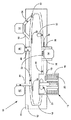
図1を参照して、ここには、本発明を実施するようになっている多段サンプル・ラック18内に収容された複数のサンプル容器20(代表的には、サンプル・テスト・チューブ)を必要に応じて自動的に予備処理することができる自動臨床化学サンプル取り扱いワークシステム10を示してある。代表的には、自動的に処理すべき患者被検物が、キャップで閉じることのできる複数の容器、たとえば、テスト・チューブに入れられてサンプル取り扱いシステム10に与えられる。サンプル容器20の各々は、患者の識別情報ならびに場合により容器内のサンプルに行うべき評価分析手順を示す容器識別マーク、たとえば、バーコードを備えている。容器は、普通、付加的な識別マークを設けてあってもよいラックのような1つまたはそれ以上のホルダ内に保持される。
Referring to FIG. 1, this requires a plurality of sample containers 20 (typically sample test tubes) housed in a
サンプル取扱いワークシステム10は、作動ベース12であって、この作動ベース上に設けてあるベルト様コンベヤ・トラック14が、サンプル・チューブ・キャリア22内に入っている複数の個々のサンプル・チューブ容器20をサンプル・チューブ装填/取り出しステーション16から自動遠心分離機24へ、キャップで閉ざされたサンプル容器20からキャップを自動的に取り外すためにキャップを自動的に取り外す自動チューブ・キャップ取り外し器30へおよび各サンプル容器20をサンプル・チューブ装填・取り出しロボット・ステーション16に戻す前に1つまたはそれ以上の通常の臨床アナライザ32、38、42へ、移送する作動ベース12を含む。ここで、4つ以上のアナライザ32、38および42をコンベヤ・トラック14によって連結してもよいが、説明を簡単にするために3つのアナライザしか図示していないことは了解されたい。サンプル取り扱いワークシステム10は、各サンプル・チューブ・キャリア22上、または、その中に設けた識別マークによってサンプル・チューブ容器20の位置を検出するための多数のセンサ(図示せず)を有する。このような追跡操作において普通のバーコード・リーダを使用してもよい。
The sample
遠心分離機24および各アナライザ38、42、32は、大雑把に言って、それぞれ、コンベヤ・トラック14からサンプル・チューブ・キャリア22を取り出すための、サンプル・チューブ・キャリア22を、遠心分離機24へ、また、遠心分離機24から移動させるための、アナライザ38、42および32から、また、アナライザ38、42および32へ移動させ、そして、アナライザ38、42および32の内外に移動させるための、種々のロボット機構26および28、40および44、またはアナライザ・トラック34および36を備えている。代表的には、装填・取り出しステーション16は、従来通りに掴み用ロボット・ハンドを備えている少なくとも2つのロボット・アーム21を包含している。
Roughly speaking, the
サンプル取り扱いワークシステム10は、在来のコンピュータ15、好ましくは、システム10の一部または別体部として収容されているマイクロプロセッサ・ベースの中央演算処理装置CPU15によって制御されて、サンプル・チューブ・キャリア22を様々なタイプの評価分析処理が行われる各作動ステーション24、30、32、38、42へ移動させる。CPU15は、イリノイ州ディアフィールドのDade Behring Inc.の販売するDimension(登録商標)型臨床化学アナライザで使用され、コンピュータ・ベースの電気機械制御プログラミングの当業者にとっては代表例であるソフトウェア、ファームウェアもしくはハードウェア・コマンド又は回路に従ってサンプル取り扱いシステム10を制御する。
The sample
図2は、チューブ直径およびチューブ長手方向高さを有する、仮想線で示す円筒形サンプル・チューブ容器20を移送するための典型的なサンプル・チューブ・キャリア22の立面図である。このサンプル・チューブ・キャリアは、中心軸線50Aを有するほぼ円筒形の下方キャリア・ボディ50と、前記軸線に沿って形成してあり、キャリア・ボディ50の頂面51から底面49に向かって延びている円筒形の孔52とを包含する。軸線50Aに沿った中心を持つオプションのくぼみ53も示してあり、このくぼみ53は、臨床サンプル・チューブ容器20に普通に見られる丸い底部を収容するように設けてある。キャリア・ボディ50は、少なくとも2つの垂直方向のアーム54を有し、これらのアームは、円筒形孔52内に対称的に配置してあり、頂面51上方に或る距離にわたって延びている。垂直方向アーム54は、中心軸線50Aに向かって下向きにテーパが付けて示すテーパ付き上端56を包含する。
FIG. 2 is an elevational view of a typical
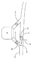
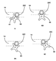
図3は、本発明で扱う代表的な例を示しており、この例では、臨床アナライザ32の要求通りに分析されたサンプル・チューブ・キャリア22Aが、アナライザ・トラック36に沿ってコンベヤ・トラック14(反時計回り方向に移動しているものとして示してある)へ戻されつつあり、その後、付加的な検査を受けるか、および/または、コンベヤ・トラック14から取り出されか、および/または、システム10内の保管場所に留められる。在来のセンサS、代表的には光線式または近接式のセンサSが、コンベヤ・トラック14に入るサンプル・チューブ・キャリア22Aとコンベヤ・トラック14に沿って移送されつつあるサンプル・チューブ・キャリア22Cとの干渉点35での潜在的な干渉を予想して、コンベヤ・トラック14に沿って計画通りに設けてある。図3に示す従来技術システムでは、コンベヤ・トラック14に隣接してセンサ作動プランジャ23を設置し、干渉点35に達する前にサンプル・チューブ・キャリア22Cの移動を止めるようにコンベヤ・トラック14の表面上方に突出するようになっているのが普通である。あるいは、センサ作動プランジャ23をアナライザ・トラック36に隣接して設置し、アナライザ・トラック36の表面から上方に突出し、干渉点35に達する前にサンプル・チューブ・キャリア22Aの移動を止めるようになっていることもある。図4に拡大して示すように、このような従来技術の解決策で生じる問題は、プランジャ23が、「遅い」ということであって、サンプル・チューブ・キャリア22Cと斜めに物理的に接触し、サンプル・チューブ20を傾かせ、おそらく、中に入っている液体患者サンプルをこぼす可能性があるということである。あるいは、図5に示すように、プランジャ23が、「もっと遅い」ということで、サンプル・チューブ・キャリア22Cをピン留めするように物理的に接触し、壁または通常コンベヤ・トラック14に沿ってレールに対してサンプル・チューブ・キャリア22Cをピン留めしてしまうこともある。
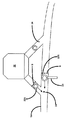
FIG. 3 shows a representative example addressed by the present invention in which the
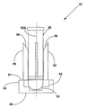
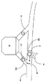
これらおよび同様の問題は本発明によって解消される。本発明によれば、コンベヤ・トラック14に沿って移送されるサンプル・チューブ・キャリア22Cのどれもが、衝突する可能性のある地点35に接近するにつれてほぼプロペラ形の回転木戸60(図10)を通って案内される。ほぼプロペラ形の回転木戸60は、サンプル・チューブ・キャリア22Cを受け入れ、適当なプランジャでもって、サンプル・チューブ・キャリア22Aが衝突する可能性のある地点35に接近したときにはいつでもその回転を止め得るようになっている。発見したことは、急激な横方向の力がサンプルに加えられた場合、(サンプルの相互汚染の可能性と共に)再懸濁および/またはこぼれの可能性が高まるということである。サンプル経路に対してほぼ直角な動きを与える従来技術の止めゲートは潜在的にこのような問題を生じさせる。本発明は、こぼれまたは再懸濁を生じさせるほどの力を持たないようにゲート速度を落とすか、または、プランジャに或る程度の弾力性を与えるべく設計した向きを有するゲートを提供することによってこのような問題を回避している。これを達成すべく、本発明では、止めシリンダに回転木戸を停止させるか、または、その速度を落とさせ、サンプルを停止または減速させる。本発明の回転木戸を用いることによって、制動力の作用を弱め、サンプルを減速させることができる。
These and similar problems are overcome by the present invention. In accordance with the present invention, a nearly propeller-shaped turnstile 60 (FIG. 10) as any
図6は、本発明の一例である装着ピン61まわりにコンベヤ・トラック14に隣接して回転自在に装着したほぼプロペラ形の回転木戸を概略的に示している。図6A、6B、6Cは、サンプル・チューブ・キャリア22Cがコンベヤ・トラック14に沿って移動するときにほぼプロペラ形の回転木戸60がどのようにして「時計方向」に回転するかを概略的に示している。
FIG. 6 schematically shows a substantially propeller-shaped rotary stool that is rotatably mounted adjacent to the
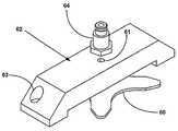
図7は、図6Bの概略図と同様の向きで回転木戸60内に受け止められたサンプル・チューブ・キャリア22Cを示す一部破断斜視図である。回転木戸60の回転を阻止して、サンプル・チューブ・キャリア22Aが潜在干渉点35に接近するときにはいつでもサンプル・チューブ・キャリア22Cの運動を停止させることができるように回転木戸錠止機構62(図9)が設けてある。あるいは、調節可能なけん引力を回転木戸60に加えてサンプル・チューブ・キャリア22Cを減速させるようにしてもよい。けん引力は、回転木戸60(図9)を完全に停止させるよりもむしろ、ピン66(図9)で回転木戸60を減速させるように調節されるプランジャ65(図9)を使用して加えてもよい。図8は、錠止機構62の下方の位置にある、図7に示している回転木戸60の簡略図である。この錠止機構62は、調節自在のプランジャ65を支持する取り付けブラケット64を包含し、このプランジャ65は、そのピン66がブラケット64にある開口部67を通して押し進められ、回転木戸60の回転を止めることができるように位置している。
FIG. 7 is a partially broken perspective view showing the
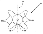
図10は、中心軸線60Aまわりに対称的に配置した2対の半径方向に延びるブレード67を包含する回転木戸60の一例を示している。ピン61を受け入れるサイズとなっている取り付け用ピンホール69が、中心軸線60Aまわりに対称的に配置した円形の取り付けパッド70中の中心に設けてある。
FIG. 10 shows an example of a
操作に当たって、図9、11に関連して説明したように、回転木戸錠止機構62の作動可能なプランジャ65は、通常、不作動位置にあり、その結果、回転木戸60は、ピン61上を自由に回転することができ、サンプル・チューブ・キャリア22Cが停止することなく干渉点35を通ってコンベヤ・トラック14に沿って移送され得るようになっている。あるいは、制動力を回転木戸60に加えて、サンプル・チューブ・キャリア22Cが干渉点35を通ってコンベヤ・トラック14に沿って移送されつつあるときにピン61上の回転を遅くし、サンプル・チューブ・キャリア22Cを減速させてもよい。結果的には、センサS1が、アナライザ32から解放され、干渉点35に接近している別のサンプル・チューブ・キャリア22Aを検出し、回転木戸錠止機構62のプランジャ65が作動させられ、ピン66が開口部67を貫いて押され、回転木戸60の回転を錠止し、そして、サンプル・チューブ・キャリア22Cが干渉点35を通ってコンベヤ・トラック14に沿って移送されるのを阻止する。プランジャ65は、在来の手段、たとえば、空気圧または電磁ソレノイドによって作動させることができる。サンプル・チューブ・キャリア22Aが干渉点35を通過した後、プランジャ65が非作動とされ、その結果、回転木戸60が再び自由に回転することができるようになり、サンプル・チューブ・キャリア22Cがコンベヤ・トラック14に沿って自由に移送されることができる。
In operation, as described in connection with FIGS. 9 and 11, the
ここで、当業者であれば、ここに開示した発明の実施形態が発明の原理を説明するものであり、なお発明の範囲内にある他の変形例も使用し得ることは了解できよう。たとえば、本発明の明らかな変形例としては、より大きい直径のサンプル・チューブ・キャリア20の場合に好ましいかもしれない3つの半径方向に延びるブレード67を包含する回転木戸60がある。本発明の別の明らかな変形例としては、一次コンベヤの近くに回転自在に装着した複数のブレードを含む任意のプロペラ形回転木戸がある。
Those skilled in the art will appreciate that the embodiments of the invention disclosed herein are illustrative of the principles of the invention and that other variations that are still within the scope of the invention may be used. For example, an obvious variation of the present invention is a
Claims (4)
Applications Claiming Priority (2)
| Application Number | Priority Date | Filing Date | Title |
|---|---|---|---|
| US11/500,672 US8232103B2 (en) | 2006-08-08 | 2006-08-08 | Merge stop gate for an automated laboratory sample handling worksystem |
| PCT/US2007/075314 WO2008021803A2 (en) | 2006-08-08 | 2007-08-07 | Merge stop gate for an automated laboratory sample handling worksystem |
Publications (1)
| Publication Number | Publication Date |
|---|---|
| JP2010500575A true JP2010500575A (en) | 2010-01-07 |
Family
ID=39051287
Family Applications (1)
| Application Number | Title | Priority Date | Filing Date |
|---|---|---|---|
| JP2009523939A Pending JP2010500575A (en) | 2006-08-08 | 2007-08-07 | Splice prevention gate for automated inspection sample handling work system |
Country Status (4)
| Country | Link |
|---|---|
| US (1) | US8232103B2 (en) |
| EP (1) | EP2049892A2 (en) |
| JP (1) | JP2010500575A (en) |
| WO (1) | WO2008021803A2 (en) |
Cited By (2)
| Publication number | Priority date | Publication date | Assignee | Title |
|---|---|---|---|---|
| JP2012112956A (en) * | 2010-11-23 | 2012-06-14 | F Hoffmann-La Roche Ag | Junction, device and process for transporting sample rack |
| WO2013051495A1 (en) * | 2011-10-07 | 2013-04-11 | 株式会社日立ハイテクノロジーズ | Specimen processing system |
Families Citing this family (15)
| Publication number | Priority date | Publication date | Assignee | Title |
|---|---|---|---|---|
| US7985375B2 (en) * | 2007-04-06 | 2011-07-26 | Qiagen Gaithersburg, Inc. | Sample preparation system and method for processing clinical specimens |
| US8703492B2 (en) * | 2007-04-06 | 2014-04-22 | Qiagen Gaithersburg, Inc. | Open platform hybrid manual-automated sample processing system |
| WO2010017258A1 (en) * | 2008-08-05 | 2010-02-11 | Monsanto Technology Llc | Automated multi-station small object analysis |
| JP5581033B2 (en) * | 2009-09-30 | 2014-08-27 | 株式会社日立ハイテクノロジーズ | Detachment mechanism for single transfer holder |
| US9953141B2 (en) | 2009-11-18 | 2018-04-24 | Becton, Dickinson And Company | Laboratory central control unit method and system |
| US10281481B2 (en) | 2010-04-20 | 2019-05-07 | Analogic Corporation | High throughput sample analyzer |
| ITMI20112082A1 (en) * | 2011-11-16 | 2013-05-17 | Inpeco Ip Ltd | PROCESS STATION OF TRANSPORT DEVICES FOR BIOLOGICAL CONTAINERS. |
| WO2013149117A2 (en) * | 2012-03-29 | 2013-10-03 | Siemens Healthcare Diagnostics Inc. | Module transport system that can be combined into an automation system |
| EP3314269A4 (en) | 2015-06-26 | 2019-01-23 | Abbott Laboratories | Reaction vessel exchanger device for a diagnostic analyzer |
| CN105203784A (en) * | 2015-09-29 | 2015-12-30 | 北京泱深生物信息技术有限公司 | Intelligent detecting system for tubular liquid specimens |
| CN105181984B (en) * | 2015-09-29 | 2017-03-01 | 北京泱深生物信息技术有限公司 | Intelligent specimen reaction analytical equipment |
| JP6742406B2 (en) * | 2015-11-12 | 2020-08-19 | エフ.ホフマン−ラ ロシュ アーゲーF. Hoffmann−La Roche Aktiengesellschaft | Sample handling device and method for sample handling |
| CN105253569B (en) * | 2015-11-15 | 2017-10-31 | 曹汝安 | A kind of annular conveyer method of blood sample test tube |
| EP3214450B1 (en) * | 2016-03-01 | 2021-09-29 | Roche Diagnostics GmbH | Transporting device for transporting a laboratory diagnostic vessel carrier |
| JP7441959B2 (en) * | 2020-02-24 | 2024-03-01 | シーメンス・ヘルスケア・ダイアグノスティックス・インコーポレイテッド | System for transporting and mixing samples |
Citations (7)
| Publication number | Priority date | Publication date | Assignee | Title |
|---|---|---|---|---|
| US2936062A (en) * | 1958-06-17 | 1960-05-10 | Martin J Wilcox | Conveyor diverting means |
| JPS5151389A (en) * | 1974-10-30 | 1976-05-06 | Olympus Optical Co | JIDOKAGAKUBUNSEKISOCHI |
| JPS57131629A (en) * | 1981-01-28 | 1982-08-14 | Kronseder Maschf Krones | Stop device for vessel feeder, particularly, bottle feeder |
| JPH02138015A (en) * | 1988-11-21 | 1990-05-28 | Mitsubishi Heavy Ind Ltd | Apparatus for stopping bottle of bottle supply apparatus |
| JPH0514021U (en) * | 1991-08-05 | 1993-02-23 | 株式会社石津製作所 | Roll product proper posture supply device in roll product transport device |
| JP3059194U (en) * | 1998-11-19 | 1999-07-02 | シグマ精器株式会社 | Blood collection tube transport system |
| JP2006103867A (en) * | 2004-10-05 | 2006-04-20 | Murata Mach Ltd | Conveyor system |
Family Cites Families (18)
| Publication number | Priority date | Publication date | Assignee | Title |
|---|---|---|---|---|
| FR2600166B1 (en) * | 1986-06-17 | 1988-10-07 | Rhone Poulenc Rech | PROCESS AND DEVICE FOR AUTOMATICALLY SUPPORTING AND ANALYZING SAMPLES OF PRODUCTS RANDOMIZED |
| JPH02112463A (en) | 1988-10-14 | 1990-04-25 | Negi Sangyo Kk | Tufted carpet |
| US5087423A (en) * | 1988-10-20 | 1992-02-11 | Olympus Optical Co., Ltd. | Automatic analyzing apparatus comprising a plurality of analyzing modules |
| US5178834A (en) * | 1989-07-19 | 1993-01-12 | Tosoh Corporation | Automatic immunoassay analyzer |
| US5209903A (en) * | 1989-09-06 | 1993-05-11 | Toa Medical Electronics, Co., Ltd. | Synthetic apparatus for inspection of blood |
| JPH0514021A (en) | 1991-07-03 | 1993-01-22 | Toshiba Corp | Support base device for dielectric resonator |
| US5380487A (en) * | 1992-05-05 | 1995-01-10 | Pasteur Sanofi Diagnostics | Device for automatic chemical analysis |
| CA2113785A1 (en) * | 1993-01-29 | 1994-07-30 | Teruaki Itoh | Sample sorting apparatus |
| US5623415A (en) * | 1995-02-16 | 1997-04-22 | Smithkline Beecham Corporation | Automated sampling and testing of biological materials |
| JP3031237B2 (en) * | 1996-04-10 | 2000-04-10 | 株式会社日立製作所 | Method of transporting sample rack and automatic analyzer for transporting sample rack |
| JP3031242B2 (en) * | 1996-05-20 | 2000-04-10 | 株式会社日立製作所 | Multi-item analyzer |
| CA2255839A1 (en) * | 1996-07-05 | 1998-01-15 | Mark Gross | Automated sample processing system |
| US5941366A (en) * | 1996-09-19 | 1999-08-24 | Labotix Automation, Inc. | Transport system for biospecimens |
| JP3428426B2 (en) * | 1997-03-26 | 2003-07-22 | 株式会社日立製作所 | Sample analysis system |
| DK0902290T3 (en) * | 1997-09-11 | 2009-02-09 | Hitachi Ltd | A sample handling system for automatic analysis devices |
| FI114661B (en) * | 2001-04-03 | 2004-11-30 | Thermo Clinical Labsystems Oy | Tubes Scaffolding |
| JP3839441B2 (en) * | 2004-03-22 | 2006-11-01 | 株式会社アイディエス | Transfer direction changing device for test tube transfer path |
| US7597630B2 (en) * | 2004-11-24 | 2009-10-06 | Water Ride Concepts, Inc. | Water amusement park conveyors |
-
2006
- 2006-08-08 US US11/500,672 patent/US8232103B2/en not_active Expired - Fee Related
-
2007
- 2007-08-07 WO PCT/US2007/075314 patent/WO2008021803A2/en active Application Filing
- 2007-08-07 EP EP07840722A patent/EP2049892A2/en not_active Withdrawn
- 2007-08-07 JP JP2009523939A patent/JP2010500575A/en active Pending
Patent Citations (7)
| Publication number | Priority date | Publication date | Assignee | Title |
|---|---|---|---|---|
| US2936062A (en) * | 1958-06-17 | 1960-05-10 | Martin J Wilcox | Conveyor diverting means |
| JPS5151389A (en) * | 1974-10-30 | 1976-05-06 | Olympus Optical Co | JIDOKAGAKUBUNSEKISOCHI |
| JPS57131629A (en) * | 1981-01-28 | 1982-08-14 | Kronseder Maschf Krones | Stop device for vessel feeder, particularly, bottle feeder |
| JPH02138015A (en) * | 1988-11-21 | 1990-05-28 | Mitsubishi Heavy Ind Ltd | Apparatus for stopping bottle of bottle supply apparatus |
| JPH0514021U (en) * | 1991-08-05 | 1993-02-23 | 株式会社石津製作所 | Roll product proper posture supply device in roll product transport device |
| JP3059194U (en) * | 1998-11-19 | 1999-07-02 | シグマ精器株式会社 | Blood collection tube transport system |
| JP2006103867A (en) * | 2004-10-05 | 2006-04-20 | Murata Mach Ltd | Conveyor system |
Cited By (4)
| Publication number | Priority date | Publication date | Assignee | Title |
|---|---|---|---|---|
| JP2012112956A (en) * | 2010-11-23 | 2012-06-14 | F Hoffmann-La Roche Ag | Junction, device and process for transporting sample rack |
| WO2013051495A1 (en) * | 2011-10-07 | 2013-04-11 | 株式会社日立ハイテクノロジーズ | Specimen processing system |
| JP2013083538A (en) * | 2011-10-07 | 2013-05-09 | Hitachi High-Technologies Corp | Specimen processing system |
| US9476806B2 (en) | 2011-10-07 | 2016-10-25 | Hitachi High-Technologies Corporation | Sample processing system |
Also Published As
| Publication number | Publication date |
|---|---|
| WO2008021803A3 (en) | 2008-04-17 |
| US20080038827A1 (en) | 2008-02-14 |
| US8232103B2 (en) | 2012-07-31 |
| WO2008021803A2 (en) | 2008-02-21 |
| EP2049892A2 (en) | 2009-04-22 |
Similar Documents
| Publication | Publication Date | Title |
|---|---|---|
| JP2010500575A (en) | Splice prevention gate for automated inspection sample handling work system | |
| EP2109764B1 (en) | Apparatus and methods for dispensing sample holders | |
| EP2142907B1 (en) | Programmable random access sample handler for use within an automated laboratory system | |
| EP1546737B1 (en) | Two-axis robot for specimen transfer | |
| US9063103B2 (en) | Conveyor of specimen containers with spur units in laboratory automation systems | |
| EP1649294B1 (en) | Assay testing diagnostic analyzer | |
| EP3964839B1 (en) | Automated diagnostic analyzers having rear accessible track systems and related methods | |
| CZ262097A3 (en) | Automated apparatus | |
| MXPA97006293A (en) | Sampling and automated tests of materials biologi | |
| EP2765426B1 (en) | Specimen processing system | |
| US6106781A (en) | Conveying system for analytical samples | |
| JPH04232871A (en) | Scanning and centering apparatus for liquid- filled container | |
| CN108780104A (en) | Automatic analysing apparatus | |
| JP2008003010A (en) | Autoanalyzer | |
| MXPA06000036A (en) | Method for increasing capacity in an automatic clinical analyzer by using modular reagent delivery means. | |
| JP6247953B2 (en) | Sample processing system | |
| US8397473B2 (en) | Apparatus for closing biological material containers | |
| JP3660397B2 (en) | incubator | |
| JP5452120B2 (en) | Automatic analyzer | |
| JPH06105259B2 (en) | Sample container transfer device | |
| JPS62218870A (en) | Container conveying method in automatic analysing apparatus and its apparatus | |
| JPH0718886B2 (en) | Pipette device with automatic nozzle chip exchange mechanism |
Legal Events
| Date | Code | Title | Description |
|---|---|---|---|
| A621 | Written request for application examination |
Free format text: JAPANESE INTERMEDIATE CODE: A621 Effective date: 20100803 |
|
| A131 | Notification of reasons for refusal |
Free format text: JAPANESE INTERMEDIATE CODE: A131 Effective date: 20120221 |
|
| A977 | Report on retrieval |
Free format text: JAPANESE INTERMEDIATE CODE: A971007 Effective date: 20120222 |
|
| A02 | Decision of refusal |
Free format text: JAPANESE INTERMEDIATE CODE: A02 Effective date: 20121023 |