JP3660397B2 - incubator - Google Patents
incubator Download PDFInfo
- Publication number
- JP3660397B2 JP3660397B2 JP15946895A JP15946895A JP3660397B2 JP 3660397 B2 JP3660397 B2 JP 3660397B2 JP 15946895 A JP15946895 A JP 15946895A JP 15946895 A JP15946895 A JP 15946895A JP 3660397 B2 JP3660397 B2 JP 3660397B2
- Authority
- JP
- Japan
- Prior art keywords
- cuvette
- holes
- elevator
- incubator
- slot
- Prior art date
- Legal status (The legal status is an assumption and is not a legal conclusion. Google has not performed a legal analysis and makes no representation as to the accuracy of the status listed.)
- Expired - Fee Related
Links
- 230000005484 gravity Effects 0.000 claims abstract description 6
- 239000003153 chemical reaction reagent Substances 0.000 description 12
- 238000004140 cleaning Methods 0.000 description 5
- 238000007599 discharging Methods 0.000 description 5
- 239000000523 sample Substances 0.000 description 5
- 230000007246 mechanism Effects 0.000 description 4
- 239000013307 optical fiber Substances 0.000 description 4
- 230000000694 effects Effects 0.000 description 3
- 239000002699 waste material Substances 0.000 description 3
- 238000001514 detection method Methods 0.000 description 2
- 238000000034 method Methods 0.000 description 2
- 230000003287 optical effect Effects 0.000 description 2
- 239000000427 antigen Substances 0.000 description 1
- 238000003556 assay Methods 0.000 description 1
- 238000003113 dilution method Methods 0.000 description 1
- 238000010438 heat treatment Methods 0.000 description 1
- 230000035945 sensitivity Effects 0.000 description 1
- 238000005406 washing Methods 0.000 description 1
Images


Classifications
-
- G—PHYSICS
- G01—MEASURING; TESTING
- G01N—INVESTIGATING OR ANALYSING MATERIALS BY DETERMINING THEIR CHEMICAL OR PHYSICAL PROPERTIES
- G01N35/00—Automatic analysis not limited to methods or materials provided for in any single one of groups G01N1/00 - G01N33/00; Handling materials therefor
- G01N35/02—Automatic analysis not limited to methods or materials provided for in any single one of groups G01N1/00 - G01N33/00; Handling materials therefor using a plurality of sample containers moved by a conveyor system past one or more treatment or analysis stations
- G01N35/025—Automatic analysis not limited to methods or materials provided for in any single one of groups G01N1/00 - G01N33/00; Handling materials therefor using a plurality of sample containers moved by a conveyor system past one or more treatment or analysis stations having a carousel or turntable for reaction cells or cuvettes
-
- G—PHYSICS
- G01—MEASURING; TESTING
- G01N—INVESTIGATING OR ANALYSING MATERIALS BY DETERMINING THEIR CHEMICAL OR PHYSICAL PROPERTIES
- G01N35/00—Automatic analysis not limited to methods or materials provided for in any single one of groups G01N1/00 - G01N33/00; Handling materials therefor
- G01N2035/00346—Heating or cooling arrangements
- G01N2035/00356—Holding samples at elevated temperature (incubation)
-
- G—PHYSICS
- G01—MEASURING; TESTING
- G01N—INVESTIGATING OR ANALYSING MATERIALS BY DETERMINING THEIR CHEMICAL OR PHYSICAL PROPERTIES
- G01N35/00—Automatic analysis not limited to methods or materials provided for in any single one of groups G01N1/00 - G01N33/00; Handling materials therefor
- G01N35/02—Automatic analysis not limited to methods or materials provided for in any single one of groups G01N1/00 - G01N33/00; Handling materials therefor using a plurality of sample containers moved by a conveyor system past one or more treatment or analysis stations
- G01N35/04—Details of the conveyor system
- G01N2035/0401—Sample carriers, cuvettes or reaction vessels
- G01N2035/0406—Individual bottles or tubes
- G01N2035/041—Individual bottles or tubes lifting items out of a rack for access
-
- G—PHYSICS
- G01—MEASURING; TESTING
- G01N—INVESTIGATING OR ANALYSING MATERIALS BY DETERMINING THEIR CHEMICAL OR PHYSICAL PROPERTIES
- G01N35/00—Automatic analysis not limited to methods or materials provided for in any single one of groups G01N1/00 - G01N33/00; Handling materials therefor
- G01N35/02—Automatic analysis not limited to methods or materials provided for in any single one of groups G01N1/00 - G01N33/00; Handling materials therefor using a plurality of sample containers moved by a conveyor system past one or more treatment or analysis stations
- G01N35/04—Details of the conveyor system
- G01N2035/0439—Rotary sample carriers, i.e. carousels
- G01N2035/0441—Rotary sample carriers, i.e. carousels for samples
-
- G—PHYSICS
- G01—MEASURING; TESTING
- G01N—INVESTIGATING OR ANALYSING MATERIALS BY DETERMINING THEIR CHEMICAL OR PHYSICAL PROPERTIES
- G01N35/00—Automatic analysis not limited to methods or materials provided for in any single one of groups G01N1/00 - G01N33/00; Handling materials therefor
- G01N35/02—Automatic analysis not limited to methods or materials provided for in any single one of groups G01N1/00 - G01N33/00; Handling materials therefor using a plurality of sample containers moved by a conveyor system past one or more treatment or analysis stations
- G01N35/04—Details of the conveyor system
- G01N2035/0439—Rotary sample carriers, i.e. carousels
- G01N2035/0443—Rotary sample carriers, i.e. carousels for reagents
-
- G—PHYSICS
- G01—MEASURING; TESTING
- G01N—INVESTIGATING OR ANALYSING MATERIALS BY DETERMINING THEIR CHEMICAL OR PHYSICAL PROPERTIES
- G01N35/00—Automatic analysis not limited to methods or materials provided for in any single one of groups G01N1/00 - G01N33/00; Handling materials therefor
- G01N35/02—Automatic analysis not limited to methods or materials provided for in any single one of groups G01N1/00 - G01N33/00; Handling materials therefor using a plurality of sample containers moved by a conveyor system past one or more treatment or analysis stations
- G01N35/04—Details of the conveyor system
- G01N2035/0439—Rotary sample carriers, i.e. carousels
- G01N2035/0444—Rotary sample carriers, i.e. carousels for cuvettes or reaction vessels
-
- Y—GENERAL TAGGING OF NEW TECHNOLOGICAL DEVELOPMENTS; GENERAL TAGGING OF CROSS-SECTIONAL TECHNOLOGIES SPANNING OVER SEVERAL SECTIONS OF THE IPC; TECHNICAL SUBJECTS COVERED BY FORMER USPC CROSS-REFERENCE ART COLLECTIONS [XRACs] AND DIGESTS
- Y10—TECHNICAL SUBJECTS COVERED BY FORMER USPC
- Y10S—TECHNICAL SUBJECTS COVERED BY FORMER USPC CROSS-REFERENCE ART COLLECTIONS [XRACs] AND DIGESTS
- Y10S435/00—Chemistry: molecular biology and microbiology
- Y10S435/809—Incubators or racks or holders for culture plates or containers
-
- Y—GENERAL TAGGING OF NEW TECHNOLOGICAL DEVELOPMENTS; GENERAL TAGGING OF CROSS-SECTIONAL TECHNOLOGIES SPANNING OVER SEVERAL SECTIONS OF THE IPC; TECHNICAL SUBJECTS COVERED BY FORMER USPC CROSS-REFERENCE ART COLLECTIONS [XRACs] AND DIGESTS
- Y10—TECHNICAL SUBJECTS COVERED BY FORMER USPC
- Y10T—TECHNICAL SUBJECTS COVERED BY FORMER US CLASSIFICATION
- Y10T436/00—Chemistry: analytical and immunological testing
- Y10T436/11—Automated chemical analysis
- Y10T436/113332—Automated chemical analysis with conveyance of sample along a test line in a container or rack
- Y10T436/114165—Automated chemical analysis with conveyance of sample along a test line in a container or rack with step of insertion or removal from test line
Landscapes
- Chemical & Material Sciences (AREA)
- Chemical Kinetics & Catalysis (AREA)
- Physics & Mathematics (AREA)
- Health & Medical Sciences (AREA)
- Life Sciences & Earth Sciences (AREA)
- Analytical Chemistry (AREA)
- Biochemistry (AREA)
- General Health & Medical Sciences (AREA)
- General Physics & Mathematics (AREA)
- Immunology (AREA)
- Pathology (AREA)
- Automatic Analysis And Handling Materials Therefor (AREA)
- Apparatus Associated With Microorganisms And Enzymes (AREA)
- Investigating Or Analysing Materials By The Use Of Chemical Reactions (AREA)
Abstract
Description
【0001】
【産業上の利用分野】
本発明はインキュベータに関し、特に、反応キュベットを読取ステーションへ接触させるように移動させると共に、インキュベータから排出する装置を有するインキュベータに関する。
【0002】
【従来の技術】
湿式分析器において、使用済の反応キュベットインキュベータから排出する排出装置が周知となっている。この装置は、前記使用済反応キュベットをインキュベータのロータに設けられた保持孔から、該保持孔に隣接して設けられた排出孔へ移送する。排出孔はキュベットを廃棄容器へ落下させるように大きな寸法にて形成されている。こうした装置は例えば米国特許公報第4406547号に開示されている。
【0003】
【発明が解決しようとする課題】
然しながら、従来の排出装置には以下のような問題がある。すなわち、この排出装置では、排出用の孔(以下、排出孔と記載する)がキュベットを保持するための孔(以下、保持孔と記載する)の半径方向外側に隣接して設けられており、振動や遠心力によりキュベットが意図せずにスライドしたり、排出すべきときよりも早く排出されるというものである。
【0004】
更に、従来の湿式分析器は読取ステーションは、例えば、米国特許公報第4406547号に記載されているように、反応キュベットは検知部へ向けて容易に移動させることができないので、反応キュベットは検知部の直近には配置されていない。屈折計 (reflectometer)や濃度計 (densitometer) に対しては上記の構成でも問題はないが、化学発光を検知するルミノメータ (luminometer)の場合には、ルミノメータの感度が高いので問題がある。化学発光は、読み取った信号を増幅するので好ましい。ルミノメータの場合には、周知の通り光学的性能を一定にするために、常に個々のキュベットを検知部の近傍の所定位置に配置させる必要がある。
【0005】
従来技術では、反応キュベットの排出装置は都合良く配設されているが、誤ってキュベットが排出されることがある。
また、多くの機構を設けると分析器の信頼性が低下するので、専用の機構を新たに設けることなく、反応キュベットを化学的発光読取ステーションに対して動作させる必要がある。
本発明はこうした問題を解決することを技術課題としている。
【0006】
【課題を解決するための手段】
本発明は、反応キュベットのための支持手段、すなわち、重力に対して前記キュベットを保持可能な寸法にて形成された第1の組の複数の孔を有する支持手段と、前記支持手段を軸線回りに動作させる第1の手段と、前記第1の組の複数の孔の各々に隣接して配設された第2の組の複数の孔と、第1の組の孔の各々と第2の組の孔の各々とを連結するスロットとを具備し、使用済キュベットを前記支持手段から除去する除去手段とを具備するインキュベータであって、前記第2の組の孔の各々は、前記キュベットよりも大きな寸法にて形成され、該第2の組の孔に配置されたキュベットが、支持されていなければ落下するようになっており、かつ、前記第2の組の孔の各々は前記ロータの回転方向の円周上に沿って前記第1の組の孔の各々から離反して配設されており、前記インキュベータは、更に、前記キュベットが前記支持手段から除去すべきときに、キュベットを前記第1の組の孔から第2の組の孔へ移動させる第2の手段を具備しているインキュベータを要旨とする。
【0007】
更に、本発明は、反応キュベットのための支持手段、すなわち、重力に対して前記キュベットを保持可能な寸法にて形成された第1の組の複数の孔を有する支持手段と、前記支持手段を軸線回りに回転させる回転手段と、前記第1の組の複数の孔の各々に隣接して配設された第2の組の複数の孔と、第1の組の孔の各々と第2の組の孔の各々とを連結するスロットとを具備し、使用済キュベットを前記支持手段から除去する除去手段とを具備するインキュベータであって、前記第2の組の孔の各々は、前記キュベットよりも大きな寸法にて形成され、該第2の組の孔に配置されたキュベットが、支持されていなければ落下するようになっており、前記スロットは、キュベットが前記第1の組の孔から前記第2の組の孔へスライドすることができない寸法にて形成されており、前記インキュベータは、更に、前記第1の組の孔の1つからキュベットを上動させるためのエレベータ手段を具備し、前記エレベータ手段は、前記スロットを通過して前記第1と第2の組の孔に対して相対的に移動できるように、前記スロットの寸法よりも小さく形成された部分を有し、更に、前記エレベータ手段は第1と第2の位置との間で移動できるように構成されており、第1の位置において前記エレベータ手段は前記複数の孔の下側に配置され、第2の位置において前記エレベータ手段は前記複数の孔の上側に配置され、前記インキュベータは、更に、前記エレベータを前記第1と第2の位置の間で上動、下動させるためのモータを具備しているインキュベータを要旨とする。
【0008】
【実施例】
以下、本発明の好ましい実施例を説明する。以下の説明では、インキュベータは、該インキュベータと協働する好ましい複数のステーションを有する分析器で使用される。また、上記の分析器において反応キュベットはエレベータにより排出のために持ち上げられる。更に、本発明は、分析器またはステーションのその余の構成の如何によらず、エレベータの構成の如何によらず有用である。
【0009】
図1に示すように、本発明のインキュベータを使用する分析器10は、好ましくは、試料供給ステーション12と、キュベット送給ステーション14(図2参照)と、試薬供給ステーション16(図1)と、インキュベータ50と、試料および試薬をインキュベータ50の外輪に配置されたキュベットに移送するための移送手段20、22と、信号試薬供給ステーション24と、信号試薬をインキュベータ50の内輪に配置されたキュベットに移送するための移送手段26と、キュベット洗浄ステーション30と、ルミノメータ32とを具備している。これらの構成要素は米国特許公報第5244633号に開示されている。試料供給ステーション12と、キュベット送給ステーション14と、試薬供給ステーション16と、移送手段20、22、26と、信号試薬供給ステーション24と、キュベット洗浄ステーション30と、ルミノメータ32としては適当な如何なる構成のものでも使用することができる。有用な試料移送装置13は、ヨーロッパ特許願第0565166号に記載された装置を含んでいる。
【0010】
供給ステーション16はロータ34を具備している。移送手段20、22、26は、回動自在に設けられたアスピレータを具備して成る。移送手段26のアスピレータは複式のプローブ36を有している。移送手段20は、好ましくは、使い捨てチップを使用する。この使い捨てチップは、採取のために供給ステーション12の移動できる。希釈工程の間に、移送手段20にて使用するために補助チップ37がターンテーブル38に配設される。他方、移送手段22用のアスピレータは、好ましくは、より長期間使用できるチップが使用される。このチップは従来と同様に洗浄ステーション40を使用する。
【0011】
分配のためにキュベットは、例えばリング42に取り付けることによりキュベット送給ステーション14に移送される。リング42はロータ16と共に移動する。プッシャ43(図2参照)が、キュベットをリング42から下側のインキュベータ50へ配設するために使用される。
【0012】
どのようなキュベットでも使用できるが、好ましくは、カップ状の容器Cが使用される。容器Cは、予め内壁面44に抗体が備えられている。この抗体は、化学発光信号を発生する抗体−抗原−標識抗体の複合体を生成する従来のサンドイッチアッセイで有効である。
【0013】
インキュベータは、好ましくは既述の米国特許公報第5244633号に開示されたインキュベータであり、好ましくは、同心に配設された外側と内側の支持リング52、54を含んで成る2つのロータを具備している。外側支持リング52、54は、キュベットCを受承、支持するための複数の保持孔57、58(図3、5参照)を有している。キュベットCは、好ましくはプッシャ43により先ずリング53に移送される。上記インキュベータは、更に、外側および内側支持リング52、54を共通の回転軸線55を中心として独立に回転させる回転駆動装置と、キュベットを外側支持リング52から内側支持リング54へ移送するための移送手段200(図3参照)と、外側および内側支持リング52、54に保持されたキュベットの内容物をインキュベートすための加熱手段とを具備する。外側および内側支持リング52、54は関連する構成要素と共に図2に略示されている。回転駆動装置は、好ましくは、外側および内側支持リング52、54の各々に設けられた歯部を具備しており、各々ピニオンギア66、68により駆動される。
【0014】
既述したように、キュベットCのための入口ポート70に加えて、種々の処理ステーションが外側および内側支持リング52、54の周辺に配設さている。図1、2を参照すると、ステーション72が外側支持リング52の上方に永久的に配設されている。ステーション72にアスピレータ20の分配チップ37(図2には図示されていない)が回動して、外側支持リング52に保持されたキュベットに試料を分配するために下動する。アスピレータ22の永久的なチップが外側支持リング52に保持されたキュベットに少なくとも第1の試薬を分配できるように、第1の試薬添加ステーション74が少なくとも外側支持リング52の上方に永久的に配設されている。アスピレータ22は、また、第2の試薬、すなわち、共役試薬を分配するために使用してもよい。信号試薬を内側支持リング54に保持されたキュベットに分配するために第2の試薬分配ステーション76が少なくとも内側支持リング54の上方に配設されている。洗浄ステーション30を使用してキュベェットを洗浄するために洗浄分配ステーション78が内側支持リング54の上方に配設されている。化学発光を読み取るためにルミノメータ32が内側支持リング54の上方に配設されている。内側支持リング54から使用済みキュベットを排出するために、ステーション82に後述するエレベータ(図3、5)が配設されている。
【0015】
適当な機構、好ましくは移送装置200を使用してキュベットが外側支持リング52から内側支持リング54へ移送される。移送装置200は、図3から図5に示すように、外側および内側支持リング52、54の上方で、該2つのリングとルミノメータ32との間に配設されたシャトル202を具備している。シャトル202は好ましくは開口部204を有している。開口部204は貫通孔にて図示されているが、破線206の高さまでの盲孔にて構成してもよい。開口部204は、キュベットCを該開口部内に持ち上げるときに摩擦抵抗なく該キュベットを受承できるように大きく形成されている。すなわち、開口部204の内径DはキュベットCの外径dよりも大きく形成されており、該開口部内のキュベットが下側から支持されていなければ、該キュベットは開口部から落下する。
【0016】
シャトル202は、分析器のフレームの一部として設けられた案内面210、212と案内ローラー214(図4参照)等の適当な案内手段により案内されて、開口部204が第1のリング52の保持孔57の直上に配置される第1の位置と、開口部204が第2のリング54の保持孔58の直上に配置される第2の位置との間で直線動作することができる。シャトル202を案内面210、212およびローラー214に対して直線動作させるために、ラック220と駆動歯車222等の適当な駆動装置が具備されている。
【0017】
外側支持リング52の保持孔57からキュベットを開口部204に(好ましくは鉛直方向に)移動させるために、押動部材230が外側支持支持リング52下側に配設されている。外側支持リング52の下側のフレームには通路232が設けられている。通路232は外側支持リング52が回転するとき、保持孔57の各々と鉛直方向に一直線上に整列できるように配設されている。一例と示す本実施例において押動部材230は、第2の駆動手段としての従来式のモータ、例えば本実施例においてリニアアクチュエータモータである駆動源236とにより鉛直方向に駆動される。すなわち、押動部材230は通路232内に配設されると共に駆動腕234に取り付けられている。押動部材230および駆動腕234が破線位置に向けて矢印238の方向に下動すると、押動部材230は保持孔57から退出して支持されるキュベットと接触せずに、保持孔およびキュベットの下側に移動する。
【0018】
外側と内側の支持リング52、54の上面240は、シャトル202によりキュベットCが外側支持リング52を通過して内側支持リング54へ移送れるとき、その案内面として作用する。
【0019】
既述の説明から移送方法は容易に理解されよう。すなわち、反応キュベットCは、シャトル202の開口部204が外側支持リング52の保持孔57の上方で鉛直線上に配置されたときに、押動部材230により外側支持リング52からシャトル202内に持ち上げられる。次いで、シャトル202が図3の矢印250で示すように半径方向内側に移動する。このとき、拘束されたキュベットが案内面としての上面240に沿ってスライドする。シャトル202の下端部252は押動部材230の頂部を避けて通過できるように構成されている。図5に示すように、開口部204が内側支持リング54の保持孔58の上方にて鉛直線上に配置されると、移送されたキュベットは単に重力により保持孔58内に落下する。キュベットは保持孔58に保持され、第2のリング54に対する処理ステーションへ移送される。
【0020】
本実施例によれば、使用済キュベットの読取および排出は以下ように実施される(図3から図6参照)。第2のエレベータ280が分析器のフレーム281において内側支持リング54の下側の第1の位置に設けられている(図3参照)。第2のエレベータは、好ましくは、リニアアクチュエータモータ284により駆動されるリードネジ283を具備している。リードネジ283の上方に、キュベットCが配置される内側支持リング54の保持孔58に接近するための開口部286が設けられている。
【0021】
キュベットが参照面に対して押接され、かつ、モータが僅かに変位できるように、フレーム281は、好ましくは弾性板バネにて構成されている。
【0022】
シャトル200の直上にプレート部材288が固定されている。プレート部材288は開口部290を有している。開口部290内に光ファイバー292が挿入される。この光ファイバー292はルミノメータ32へ延設されており、ルミノメータの光学的読取部の一部を構成する。シャトル200がその内側位置(図5参照)に移動したときに、開口部290と光ファイバー292は一直線上に配設される。この位置において、第2のエレベータ280は充分に上動したときに破線で示すキュベットC′を光ファイバー292に押接することが可能となる。これにより、ルミノメータ32はキュベットC′で生じる化学発光反応からの最大光を確実に受光し読み取る。
【0023】
読取の後にキュベットC′を排出するために、内側支持リング54は第2の組の孔として複数の排出孔300(図6参照)を有している。複数の排出孔300の各々はリング54において周方向に等間隔で配設された保持孔58の各々と連結されている。すなわち、保持孔58の各々に対して、排出孔300が回転方向の円周302に沿って配設され、かつ、スロット304を介して保持孔58に連結されている。排出孔300の内径D1がキュベットC、C′の最大直径よりも充分に大きく、キュベットが下側から支持されていないと、排出孔300を通過して落下できるようになっている。これを防止するために、固定式の支持レール310が第2のエレベータ280と排出ステーション82とを除く位置に設けられており、内側支持リング54が支持レール310の上方を通過する。
【0024】
スロット304の最大幅D2はキュベットC、C′の直径D3よりも小さくなっており、キュベットはスロット304および排出孔300内にスライドすることはできない。リードネジ283の最大外径D4はスロットの最大幅D2よりも小さくなっており、リードネジ283がスロット304を通過して突出していても、内側支持リング54は回転することが可能である。これにより、リードネジ283は、内側支持リング54に対して相対的に、保持孔から排出孔300へ移動することができる(この間キュベットC′は開口部204内に残っている)。このとき、リードネジ283が下動してキュベットC′を排出孔300内に移送する。キュベットC′は、その下側に支持レール310が存在する間、排出孔300内に保持される。
【0025】
然しながら、排出ステーション82において支持レール310が途切れると(図2参照)、その下側には使用済キュベットが集められる廃棄瓶または廃棄容器まで延びるシュートが設けられている。すなわち、内側支持リング54が回転すると、内部に使用済キュベットを保持する排出孔300が、ステーション82の上記シュートと一致するまで回転し、キュベットがインキュベータから落下、排出される。
【0026】
既述の構成により、第2のエレベータがキュベットをルミノメータに接触させるように移動させると共に、読取後のキュベットの排出工程を開始させる、すなわち、排出孔300にキュベットを移送するために使用されることが理解されよう。そして、排出孔300が支持レールが存在しないステーション82において落下させる。
【0027】
然しながら、第2のエレベータにより読取後のキュベットC′が排出孔300に下ろされてから僅かの後に、該キュベットC′を保持孔58から排出孔300へ簡単に移送するために、独立のエレベータを設けてもよいことは当業者に理解されよう。
【0028】
【発明の効果】
既述の説明から明らかなように、本発明は、使用済キュベットを排出すべきときよりも速く除去される危惧なく、使用済反応キュベットを容易にインキュベータから除去可能とする効果を奏する。
更に、本発明の他の利点、効果は、ルミノメータの読取ステーションへキュベットを移動させ専用の機構を設けなくとも、キュベットを移動させることが可能である点である。
【図面の簡単な説明】
【図1】本発明のインキュベータを適用する分析器の部分平面図である。
【図2】本発明のインキュベータの2つのロータの略斜視図である。
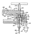
【図3】インキュベータの移送装置およびエレベータの部分断面図である。
【図4】図3において矢視線IV−IVに沿う断面図である。
【図5】インキュベータの移送装置およびエレベータの部分断面図である。
【図6】ロータの部分平面図であり、キュベットを排出するための排出孔とスロットとを示す図である。
【符号の説明】
50…インキュベータ
52…外側支持リング
54…内側支持リング
58…保持孔
280…第2のエレベータ
284…リニアアクチュエータモータ
300…排出孔
304…スロット[0001]
[Industrial application fields]
The present invention relates to an incubator, and more particularly to an incubator having a device for moving a reaction cuvette into contact with a reading station and for discharging the incubator.
[0002]
[Prior art]
In wet analyzers, discharge devices that discharge from used reaction cuvette incubators are well known. This apparatus transfers the used reaction cuvette from a holding hole provided in the rotor of the incubator to a discharge hole provided adjacent to the holding hole. The discharge hole is formed with a large size so as to drop the cuvette into the waste container. Such an apparatus is disclosed, for example, in U.S. Pat. No. 4,406,547.
[0003]
[Problems to be solved by the invention]
However, the conventional discharging apparatus has the following problems. That is, in this discharge device, a discharge hole (hereinafter referred to as a discharge hole) is provided adjacent to a radially outer side of a hole (hereinafter referred to as a holding hole) for holding a cuvette, The cuvette slides unintentionally due to vibration or centrifugal force, or is discharged earlier than when it should be discharged.
[0004]
Furthermore, the conventional wet analyzer has a reading station, for example, as described in U.S. Pat. No. 4,406,547, because the reaction cuvette cannot be easily moved toward the detection unit. It is not placed in the immediate vicinity. There is no problem with the above configuration for a refractometer and a densitometer, but there is a problem with a luminometer that detects chemiluminescence because the sensitivity of the luminometer is high. Chemiluminescence is preferred because it amplifies the read signal. In the case of a luminometer, as is well known, in order to keep the optical performance constant, it is necessary to always arrange individual cuvettes at predetermined positions in the vicinity of the detection unit.
[0005]
In the prior art, the reaction cuvette discharging apparatus is conveniently arranged, but the cuvette may be accidentally discharged.
In addition, if many mechanisms are provided, the reliability of the analyzer is lowered. Therefore, it is necessary to operate the reaction cuvette with respect to the chemiluminescence reading station without newly providing a dedicated mechanism.
This invention makes it a technical subject to solve such a problem.
[0006]
[Means for Solving the Problems]
The present invention provides a support means for a reaction cuvette, that is, a support means having a first set of a plurality of holes formed with dimensions capable of holding the cuvette against gravity, and the support means around an axis. A first means for operating the second set, a second set of holes disposed adjacent to each of the first set of holes, a first set of holes and a second set of holes. A slot for connecting each of the holes in the set, and a removing means for removing the used cuvette from the support means, wherein each of the second set of holes is from the cuvette Are formed in large dimensions, and the cuvettes disposed in the second set of holes are adapted to fall if not supported, and each of the second set of holes is provided in the rotor. Each of the first set of holes along a circumference in the direction of rotation; The incubator is further spaced apart from the second set of holes to move the cuvette from the first set of holes to the second set of holes when the cuvette is to be removed from the support means. The gist is an incubator equipped with means.
[0007]
Furthermore, the present invention provides a supporting means for a reaction cuvette, i.e., a supporting means having a first set of a plurality of holes formed with dimensions capable of holding the cuvette against gravity, and the supporting means. A rotating means for rotating about an axis; a second plurality of holes disposed adjacent to each of the first set of holes; a first set of holes; and a second set of holes; A slot for connecting each of the holes in the set, and a removing means for removing the used cuvette from the support means, wherein each of the second set of holes is from the cuvette And the cuvette disposed in the second set of holes is configured to fall if not supported, and the slot is configured so that the cuvette is removed from the first set of holes. Can slide into the second set of holes. The incubator further comprises elevator means for moving the cuvette up from one of the first set of holes, the elevator means passing through the slot. A portion formed smaller than the size of the slot so as to be movable relative to the first and second sets of holes; and the elevator means includes first and second positions; The elevator means is disposed below the plurality of holes in a first position, and the elevator means is disposed above the plurality of holes in a second position. The incubator is further summarized as an incubator including a motor for moving the elevator up and down between the first and second positions.
[0008]
【Example】
Hereinafter, preferred embodiments of the present invention will be described. In the following description, the incubator is used with an analyzer having a preferred plurality of stations that cooperate with the incubator. In the above analyzer, the reaction cuvette is lifted for discharge by an elevator. Furthermore, the present invention is useful regardless of the configuration of the elevator, regardless of the configuration of the analyzer or station.
[0009]
As shown in FIG. 1, the
[0010]
The
[0011]
For dispensing, the cuvette is transferred to the
[0012]
Any cuvette can be used, but preferably a cup-shaped container C is used. The container C is previously provided with an antibody on the inner wall surface 44. This antibody is useful in conventional sandwich assays that produce antibody-antigen-labeled antibody complexes that generate chemiluminescent signals.
[0013]
The incubator is preferably the incubator disclosed in the aforementioned US Pat. No. 5,244,633, and preferably comprises two rotors comprising outer and inner support rings 52, 54 arranged concentrically. ing. The outer support rings 52 and 54 have a plurality of holding
[0014]
As previously mentioned, in addition to the inlet port 70 for the cuvette C, various processing stations are disposed around the outer and inner support rings 52,54. With reference to FIGS. 1 and 2, a station 72 is permanently disposed above the
[0015]
A cuvette is transferred from the
[0016]
The
[0017]
In order to move the cuvette from the holding
[0018]
The upper surfaces 240 of the outer and inner support rings 52, 54 act as guide surfaces when the cuvette C is transferred by the
[0019]
The transfer method will be easily understood from the above description. That is, the reaction cuvette C is lifted from the
[0020]
According to the present embodiment, reading and discharging of the used cuvette is performed as follows (see FIGS. 3 to 6). A
[0021]
The
[0022]
A
[0023]
In order to discharge the cuvette C ′ after reading, the
[0024]
The maximum width D2 of the
[0025]
However, when the
[0026]
According to the configuration described above, the second elevator is used to move the cuvette to contact the luminometer and to start the cuvette discharge process after reading, that is, to transfer the cuvette to the
[0027]
However, a short time after the read cuvette C ′ is lowered into the
[0028]
【The invention's effect】
As is apparent from the above description, the present invention has an effect that the used reaction cuvette can be easily removed from the incubator without fear that the used cuvette is removed faster than when the used cuvette should be discharged.
Furthermore, another advantage and effect of the present invention is that the cuvette can be moved without moving the cuvette to the luminometer reading station and providing a dedicated mechanism.
[Brief description of the drawings]
FIG. 1 is a partial plan view of an analyzer to which an incubator of the present invention is applied.
FIG. 2 is a schematic perspective view of two rotors of the incubator of the present invention.
FIG. 3 is a partial cross-sectional view of an incubator transfer device and an elevator.
4 is a cross-sectional view taken along line IV-IV in FIG.
FIG. 5 is a partial cross-sectional view of an incubator transfer device and an elevator.
FIG. 6 is a partial plan view of a rotor, showing a discharge hole and a slot for discharging a cuvette.
[Explanation of symbols]
50 ...
Claims (2)
前記支持手段を軸線回りに動作させる第1の手段と、
前記第1の組の複数の孔の各々に隣接して配設された第2の組の複数の孔と、第1の組の孔の各々と第2の組の孔の各々とを連結するスロットとを具備し、使用済キュベットを前記支持手段から除去する除去手段とを具備するインキュベータであって、
前記第2の組の孔の各々は、前記キュベットよりも大きな寸法にて形成され、該第2の組の孔に配置されたキュベットが、支持されていなければ落下するようになっており、かつ、前記第2の組の孔の各々は前記ロータの回転方向の円周上に沿って前記第1の組の孔の各々から離反して配設されており、
前記インキュベータは、更に、前記キュベットが前記支持手段から除去すべきときに、キュベットを前記第1の組の孔から第2の組の孔へ移動させる第2の手段を具備しているインキュベータ。A support means for the reaction cuvette, i.e. a support means having a first set of holes formed in dimensions capable of holding said cuvette against gravity;
First means for operating the support means about an axis;
A second set of holes disposed adjacent to each of the first set of holes, and each of the first set of holes and each of the second set of holes are coupled to each other. An incubator comprising a slot and a removing means for removing the used cuvette from the support means,
Each of the second set of holes is sized to be larger than the cuvette, and the cuvette disposed in the second set of holes is adapted to fall if not supported; and Each of the second set of holes is disposed away from each of the first set of holes along a circumference in a rotation direction of the rotor;
The incubator further comprises second means for moving the cuvette from the first set of holes to the second set of holes when the cuvette is to be removed from the support means.
前記支持手段を軸線回りに回転させる回転手段と、
前記第1の組の複数の孔の各々に隣接して配設された第2の組の複数の孔と、第1の組の孔の各々と第2の組の孔の各々とを連結するスロットとを具備し、使用済キュベットを前記支持手段から除去する除去手段とを具備するインキュベータであって、
前記第2の組の孔の各々は、前記キュベットよりも大きな寸法にて形成され、該第2の組の孔に配置されたキュベットが、支持されていなければ落下するようになっており、
前記スロットは、キュベットが前記第1の組の孔から前記第2の組の孔へスライドすることができない寸法にて形成されており、
前記インキュベータは、更に、前記第1の組の孔の1つからキュベットを上動させるためのエレベータ手段を具備し、
前記エレベータ手段は、前記スロットを通過して前記第1と第2の組の孔に対して相対的に移動できるように、前記スロットの寸法よりも小さく形成された部分を有し、更に、前記エレベータ手段は第1と第2の位置との間で移動できるように構成されており、第1の位置において前記エレベータ手段は前記複数の孔の下側に配置され、第2の位置において前記エレベータ手段は前記複数の孔の上側に配置され、
前記インキュベータは、更に、前記エレベータを前記第1と第2の位置の間で上動、下動させるためのモータを具備しているインキュベータ。A support means for the reaction cuvette, i.e. a support means having a first set of holes formed in dimensions capable of holding said cuvette against gravity;
Rotating means for rotating the supporting means about an axis;
A second set of holes disposed adjacent to each of the first set of holes, and each of the first set of holes and each of the second set of holes are coupled to each other. An incubator comprising a slot and a removing means for removing the used cuvette from the support means,
Each of the second set of holes is formed with a size larger than that of the cuvette, and the cuvette disposed in the second set of holes is allowed to fall if not supported,
The slot is formed with a dimension that prevents the cuvette from sliding from the first set of holes to the second set of holes;
The incubator further comprises elevator means for moving the cuvette up from one of the first set of holes;
The elevator means has a portion formed smaller than the size of the slot so that the elevator means can move relative to the first and second sets of holes through the slot, and The elevator means is configured to be movable between first and second positions, wherein the elevator means is disposed below the plurality of holes in the first position, and the elevator means is in the second position. Means is disposed above the plurality of holes;
The incubator further includes a motor for moving the elevator up and down between the first and second positions.
Applications Claiming Priority (2)
| Application Number | Priority Date | Filing Date | Title |
|---|---|---|---|
| US08/266,070 US5456883A (en) | 1994-06-27 | 1994-06-27 | Mechanism for reading and removing reaction cuvettes in an incubator |
| US266070 | 1999-03-10 |
Publications (2)
| Publication Number | Publication Date |
|---|---|
| JPH08178930A JPH08178930A (en) | 1996-07-12 |
| JP3660397B2 true JP3660397B2 (en) | 2005-06-15 |
Family
ID=23013040
Family Applications (1)
| Application Number | Title | Priority Date | Filing Date |
|---|---|---|---|
| JP15946895A Expired - Fee Related JP3660397B2 (en) | 1994-06-27 | 1995-06-26 | incubator |
Country Status (5)
| Country | Link |
|---|---|
| US (1) | US5456883A (en) |
| EP (1) | EP0690309B1 (en) |
| JP (1) | JP3660397B2 (en) |
| AT (1) | ATE218710T1 (en) |
| DE (1) | DE69526881T2 (en) |
Families Citing this family (15)
| Publication number | Priority date | Publication date | Assignee | Title |
|---|---|---|---|---|
| ID18376A (en) * | 1996-01-29 | 1998-04-02 | Johnson & Johnson Consumer | DETERGENT COMPOSITIONS |
| US6063591A (en) * | 1997-05-14 | 2000-05-16 | 3M Innovative Properties Company | System for measuring the efficacy of a sterilization cycle |
| US6025189A (en) * | 1997-05-14 | 2000-02-15 | 3M Innovative Properties Company | Apparatus for reading a plurality of biological indicators |
| US5863790A (en) * | 1997-05-14 | 1999-01-26 | Minnesota Mining And Manfacturing Company | Biological sterility indicator |
| FI113703B (en) * | 1999-03-12 | 2004-05-31 | Innotrac Diagnostics Oy | Diagnostic measuring device |
| FR2804510B1 (en) * | 2000-01-28 | 2003-02-07 | Biomerieux Sa | WC BASES, AUTOMATED BIOLOGICAL ANALYSIS APPARATUS USING SUCH WC WORKS, MEANS FOR TRANSFERRING WC WORKS IN SUCH APPARATUS, AND TRANSFER METHOD |
| US20030087447A1 (en) * | 2001-11-08 | 2003-05-08 | Blouin Matthew R | Sample well strip |
| USD481133S1 (en) | 2002-04-18 | 2003-10-21 | Instrumentation Laboratory Company | Sample well-strip for an automated sample analyzer |
| US7731899B2 (en) | 2007-02-08 | 2010-06-08 | Biokit, S.A. | Apparatus and methods for dispensing sample holders |
| EP1970711A1 (en) * | 2007-03-16 | 2008-09-17 | Radiometer Medical ApS | Reagent cup device |
| EP2893320B1 (en) * | 2012-08-20 | 2020-12-23 | Siemens Healthcare Diagnostics Inc. | Clam-shell luminometer |
| ES3038129T3 (en) | 2015-06-26 | 2025-10-09 | Abbott Lab | Rotating device in a diagnostic analyzer |
| CN105301266A (en) * | 2015-11-05 | 2016-02-03 | 南通诺赛自动化科技有限公司 | Automatic in-vitro detection instrument |
| WO2020087252A1 (en) * | 2018-10-30 | 2020-05-07 | 深圳迎凯生物科技有限公司 | Reaction device and immunity analyzer |
| CN117485723A (en) * | 2023-09-27 | 2024-02-02 | 江苏汇先医药技术有限公司 | Application method of digestive tract tumor marker combination detection kit |
Family Cites Families (8)
| Publication number | Priority date | Publication date | Assignee | Title |
|---|---|---|---|---|
| US4406547A (en) * | 1979-08-07 | 1983-09-27 | Olympus Optical Company Limited | Apparatus for effecting automatic analysis |
| US4595562A (en) * | 1981-07-20 | 1986-06-17 | American Hospital Supply Corporation | Loading and transfer assembly for chemical analyzer |
| DE3130245A1 (en) * | 1981-07-31 | 1983-02-17 | Bodenseewerk Perkin-Elmer & Co GmbH, 7770 Überlingen | SAMPLER FOR GAS SAMPLING IN GAS CHROMATOGRAPHY |
| US4539645A (en) * | 1982-08-23 | 1985-09-03 | Conoco Inc. | Automated sample analyzer for induction furnace analysis |
| JPS61274268A (en) * | 1985-05-30 | 1986-12-04 | Toshiba Corp | Automatic chemical analyzer |
| GB8529889D0 (en) * | 1985-12-04 | 1986-01-15 | Cardiff Energy & Resources | Luminometer construction |
| US5093268A (en) * | 1988-04-28 | 1992-03-03 | Igen, Inc. | Apparatus for conducting a plurality of simultaneous measurements of electrochemiluminescent phenomena |
| US5244633A (en) * | 1992-05-22 | 1993-09-14 | Eastman Kodak Company | Analyzer incubator with plural independently driven rings supporting cuvettes |
-
1994
- 1994-06-27 US US08/266,070 patent/US5456883A/en not_active Expired - Fee Related
-
1995
- 1995-06-26 AT AT95304492T patent/ATE218710T1/en not_active IP Right Cessation
- 1995-06-26 DE DE69526881T patent/DE69526881T2/en not_active Expired - Fee Related
- 1995-06-26 EP EP95304492A patent/EP0690309B1/en not_active Expired - Lifetime
- 1995-06-26 JP JP15946895A patent/JP3660397B2/en not_active Expired - Fee Related
Also Published As
| Publication number | Publication date |
|---|---|
| EP0690309A2 (en) | 1996-01-03 |
| EP0690309A3 (en) | 1997-01-15 |
| DE69526881D1 (en) | 2002-07-11 |
| EP0690309B1 (en) | 2002-06-05 |
| US5456883A (en) | 1995-10-10 |
| JPH08178930A (en) | 1996-07-12 |
| DE69526881T2 (en) | 2002-11-21 |
| ATE218710T1 (en) | 2002-06-15 |
Similar Documents
| Publication | Publication Date | Title |
|---|---|---|
| JP3660397B2 (en) | incubator | |
| EP0703457B1 (en) | Analyzing apparatus | |
| JP5797605B2 (en) | A device to remove and recap the sample tube | |
| JP2616360B2 (en) | Blood coagulation analyzer | |
| US4259289A (en) | Apparatus for retrieving liquid samples from test tubes | |
| US4568519A (en) | Apparatus for processing analysis slides | |
| CN102050413B (en) | Cover opener and automatic analyzing device using same | |
| CN108732164B (en) | Full-automatic chemiluminescence immunoassay instrument | |
| JP2674937B2 (en) | Analytical sample processing station | |
| JPS6125100B2 (en) | ||
| US10684300B2 (en) | Rotating disc type fecal occult blood detection analyzer | |
| JPH08160051A (en) | Analyzer having plurality of vertically arranged incubators | |
| JPS5967443A (en) | Automatic sampler | |
| CN113620221A (en) | Automatic cover opening device | |
| JP3759638B2 (en) | incubator | |
| CN211528436U (en) | Detection module | |
| CN205506849U (en) | Container rotation device | |
| JP2616359B2 (en) | Blood coagulation analyzer | |
| CN116840016B (en) | Automatic whole blood sample preparation instrument and working method thereof | |
| JP3558833B2 (en) | Reaction tube transfer device | |
| JP2001165937A (en) | Automatic biochemical analyzer | |
| JP3152711B2 (en) | Automatic analyzer and automatic analysis method | |
| CN223966589U (en) | Sample detection discarding device | |
| JPH0443818Y2 (en) | ||
| JPH0355101Y2 (en) |
Legal Events
| Date | Code | Title | Description |
|---|---|---|---|
| TRDD | Decision of grant or rejection written | ||
| A01 | Written decision to grant a patent or to grant a registration (utility model) |
Free format text: JAPANESE INTERMEDIATE CODE: A01 Effective date: 20050215 |
|
| A61 | First payment of annual fees (during grant procedure) |
Free format text: JAPANESE INTERMEDIATE CODE: A61 Effective date: 20050317 |
|
| R150 | Certificate of patent or registration of utility model |
Free format text: JAPANESE INTERMEDIATE CODE: R150 |
|
| LAPS | Cancellation because of no payment of annual fees |