JP2010276080A - Energy absorbing member and structure in which the energy absorbing member is installed - Google Patents
Energy absorbing member and structure in which the energy absorbing member is installed Download PDFInfo
- Publication number
- JP2010276080A JP2010276080A JP2009127747A JP2009127747A JP2010276080A JP 2010276080 A JP2010276080 A JP 2010276080A JP 2009127747 A JP2009127747 A JP 2009127747A JP 2009127747 A JP2009127747 A JP 2009127747A JP 2010276080 A JP2010276080 A JP 2010276080A
- Authority
- JP
- Japan
- Prior art keywords
- energy absorbing
- absorbing member
- reinforced concrete
- steel
- bracket
- Prior art date
- Legal status (The legal status is an assumption and is not a legal conclusion. Google has not performed a legal analysis and makes no representation as to the accuracy of the status listed.)
- Pending
Links
Images


Abstract
Description
本発明は、鋼材の塑性変形を利用した履歴型のエネルギー吸収部材およびこれを用いた構造物に関する。 The present invention relates to a hysteretic energy absorbing member utilizing plastic deformation of a steel material and a structure using the same.
従来のエネルギー吸収部材としては、軸方向の塑性変形により履歴エネルギー吸収するものと、せん断変形により履歴エネルギー吸収するものがある。
そして、軸方向の塑性変形により履歴エネルギー吸収するものとしては、例えば特許文献1(実開昭63-101603号公報)、特許文献2(特開平7-229204号公報)などのように軸材の座屈を防止するために鋼管およびコンクリートにより補剛したものがある。また、軸材の補剛の他の態様として、特許文献3(実開平-6-71602号公報)のように形鋼で補剛したもの、特許文献4(特開平4-149345号公報)や特許文献5(特開平7-324377号公報)のように鋼管で補剛したもの、さらには特許文献6(特開平7-324378号公報)のように鉄筋コンクリートで補剛したものがある。
Conventional energy absorbing members include those that absorb hysteresis energy by plastic deformation in the axial direction and those that absorb hysteresis energy by shear deformation.
And as for what absorbs hysteresis energy by plastic deformation in the axial direction, for example, Patent Document 1 (Japanese Utility Model Publication No. 63-101603), Patent Document 2 (Japanese Patent Application Laid-Open No. 7-229204), etc. Some are stiffened with steel pipes and concrete to prevent buckling. Further, as other modes of stiffening of the shaft member, those stiffened with a shape steel like Patent Document 3 (Japanese Utility Model Laid-Open No. 6-71602), Patent Document 4 (Japanese Patent Laid-Open No. 4-149345), There are those stiffened with steel pipes as in Patent Document 5 (Japanese Patent Laid-Open No. 7-324377), and further stiffened with reinforced concrete as in Patent Document 6 (Japanese Patent Laid-Open No. 7-324378).
一方、せん断変形により履歴エネルギー吸収するものとしては、例えば特許文献7(特開平4-312682号公報)、特許文献8(特開平10-82201号公報)、特許文献9(実用新案登録第2556764号公報)、特許文献10(特開平10-153012号公報)等に開示されているように、鉄骨構造物などの架構に間柱を設け、該間柱の中央部に制振部材を設置するというものである。具体的には、特許文献10に開示されたように、鉄骨構造物などの架構に設置される耐震部材において、H形鋼のウェブに開口部を設け、該開口部に前記ウェブの降伏耐力より低い降伏耐力の鋼材を接合したことを特徴とするものである(特許文献10の請求項2参照)。 On the other hand, examples of devices that absorb hysteresis energy by shear deformation include, for example, Patent Document 7 (Japanese Patent Laid-Open No. 4-312682), Patent Document 8 (Japanese Patent Laid-Open No. 10-82201), and Patent Document 9 (Registered Utility Model No. 2556764). Gazette), Patent Document 10 (Japanese Patent Laid-Open No. 10-153012), and the like, a stud is provided on a frame such as a steel structure, and a damping member is installed at the center of the stud. is there. Specifically, as disclosed in Patent Document 10, in an earthquake-resistant member installed in a frame such as a steel structure, an opening is provided in an H-shaped steel web, and the yield strength of the web is determined in the opening. It is characterized by joining steel materials having a low yield strength (see claim 2 of Patent Document 10).
せん断変形により履歴エネルギー吸収するエネルギー吸収部材は、上記の特許文献10に示されるように、架構にH形鋼のブラケットを設け、このブラケット間に例えば低降伏点鋼材を接合するというものである。このような構造のものは、構面内の1方向に作用させることを目的としたものであり、1箇所で2方向に作用せしめることは困難であった。仮に、従来のような構造ものを2方向に作用させようとする場合には大きなスペースが必要となり、構造物の平面計画上の支障が生ずることになる。 An energy absorbing member that absorbs hysteresis energy by shear deformation is provided with H-shaped steel brackets on a frame and, for example, a low-yield point steel material is joined between the brackets as shown in Patent Document 10 above. Such a structure is intended to act in one direction within the construction surface, and it is difficult to act in two directions at one location. If a conventional structure is to be applied in two directions, a large space is required, resulting in trouble in the plan of the structure.
本発明は係る課題を解決するためになされたものであり、コンパクトで架構の構面内の1箇所において複数方向に作用させることが可能なエネルギー吸収部材、及び該エネルギー吸収部材を適用した構造物を提供することを目的としている。 The present invention has been made in order to solve the problems, and is a compact energy absorbing member capable of acting in a plurality of directions at one location in the frame of the frame, and a structure to which the energy absorbing member is applied. The purpose is to provide.
(1)本発明に係るエネルギー吸収部材は、鋼材のせん断塑性変形を利用した履歴型のエネルギー吸収部材であって、上下に配置されて構造物に固定される一対の角形鋼管状部材を備えてなるブラケット部材と、これら一対のブラケット部材間の上下で対応する面間に亘って塑性化部を有するダンパー部材をボルト接合してなることを特徴とするものである。
なお、ダンパー部材は、上下一対のブラケット部材間に、対向する面同士が対になるように設置するのが好ましい。
(1) An energy absorbing member according to the present invention is a hysteretic energy absorbing member utilizing shear plastic deformation of a steel material, and includes a pair of rectangular steel tubular members that are arranged vertically and fixed to a structure. And a damper member having a plasticizing portion between the corresponding upper and lower surfaces between the pair of bracket members.
In addition, it is preferable to install a damper member so that the surfaces which oppose may be paired between a pair of upper and lower bracket members.
(2)また、上記(1)に記載のものにおいて、前記ダンパー部材は、前記ブラケット部材にボルト接合可能な上下一対の板材と、該板材間に溶接接合されると共にウェブ部分に開口部が形成された溝形形状の鋼材と、前記開口部に接合されて塑性変形によりエネルギーを吸収するせん断パネルとを備えてなることを特徴とするものである。 (2) Further, in the above (1), the damper member is a pair of upper and lower plates that can be bolted to the bracket member, and welded between the plates, and an opening is formed in the web portion. And a shear panel that is joined to the opening and absorbs energy by plastic deformation.
(3)また、上記(2)に記載のものにおいて、前記せん断パネルの少なくとも短辺側の幅厚比が20から60の範囲に設定されていることを特徴とするものである。 (3) Further, in the above (2), the width-thickness ratio of at least the short side of the shear panel is set in the range of 20 to 60.
(4)また、上記(2)または(3)に記載のものにおいて、前記せん断パネルに、低降伏点鋼を用いることを特徴とするものである。 (4) Further, in the above (2) or (3), a low yield point steel is used for the shear panel.
(5)また、上記(2)乃至(4)のいずれかに記載のものにおいて、前記せん断パネルの座屈を防止するための補剛材を有することを特徴とするものである。 (5) Further, in any of the above (2) to (4), it has a stiffener for preventing buckling of the shear panel.
(6)また、上記(1)乃至(5)のいずれかに記載のものにおいて、前記ブラケット部材は、鉄筋コンクリート又はプレキャスト鉄筋コンクリートからなる鉄筋コンクリート部を有し、該鉄筋コンクリート部に前記角形鋼管状部材がその径の1.0倍以上埋め込まれており、前記ブラケット部は前記鉄筋コンクリート部を介して構造物に固定されることを特徴とするものである。 (6) Moreover, in the thing in any one of said (1) thru | or (5), the said bracket member has a reinforced concrete part which consists of reinforced concrete or precast reinforced concrete, and the said square steel tubular member is the said reinforced concrete part. It is embedded at 1.0 times or more in diameter, and the bracket portion is fixed to the structure through the reinforced concrete portion.
(7)また、上記(6)に記載のものにおいて、前記角形鋼管状部材と、前記鉄筋コンクリートまたはプレキャスト鉄筋コンクリートとの間の付着力を増大するための付着力増大手段を設けたことを特徴とするものである。 (7) Further, in the above (6), there is provided an adhesion increasing means for increasing the adhesion between the rectangular steel tubular member and the reinforced concrete or precast reinforced concrete. Is.
(8)また、本発明に係る構造物は、上記(1)乃至(7)のいずれかに記載のエネルギー吸収部材を設置したことを特徴とするものである。 (8) Moreover, the structure which concerns on this invention installed the energy absorption member in any one of said (1) thru | or (7), It is characterized by the above-mentioned.
本発明においては、上下に配置されて構造物に固定される一対の角形鋼管状部材を備えてなるブラケット部材と、これら一対のブラケット部材間の上下で対応する面間に亘って塑性化部を有するダンパー部材をボルト接合してなるので、コンパクトな形状で複数方向にエネルギー吸収能力を発揮させることができる。 In the present invention, a bracket member comprising a pair of rectangular steel tubular members that are arranged vertically and fixed to a structure, and a plasticizing portion between the corresponding surfaces above and below between the pair of bracket members. Since the damper member is bolted, the energy absorbing ability can be exhibited in a plurality of directions with a compact shape.
[実施の形態1]
図1乃至図5に基づいて本発明の実施の形態1に係るエネルギー吸収部材を説明する。
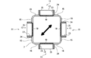
本実施の形態に係るエネルギー吸収部材1は、図1に示すように、構造物の上側の梁2の交点に接合される上側ブラケット部材3と、下側の梁5の交点に接合される下側ブラケット部材7と、上側ブラケット部材3と下側ブラケット部材7の間に高力ボルト9によってボルト接合されたダンパー部材11を備えている。
[Embodiment 1]
Based on FIG. 1 thru | or FIG. 5, the energy absorption member which concerns on
As shown in FIG. 1, the
<ブラケット部材>
上側ブラケット部材3は、その上端側が梁の交点に接合され、下端側にダンパー部材11の上端部がボルト接合されている。また、下側ブラケット部材7は、その下端部が梁の交点に接合され、上端側にダンパー部材11の下端部がボルト接合されている。
上側ブラケット部材3と下側ブラケット部材7は同形状であり、共に軸方向直交断面が四角形の角形鋼管12によって形成されている。角形鋼管12は本発明の角形鋼管状部材の一態様である。
上側ブラケット部材3と下側ブラケット部材7はその周面の各面が同一平面になるように上下に配置され、上下のブラケット部材間において対応する面同士に亘ってダンパー部材11が設置されている。
<Bracket member>
The upper bracket member 3 has an upper end joined to the intersection of the beams and an upper end of the
The upper bracket member 3 and the
The upper bracket member 3 and the
なお、本実施の形態においては、角形鋼管状部材の一態様として角形鋼管12を用いた例を示したが、他の態様として鉄骨を溶接4面BOXの鉄骨造としてもよく、あるいはコンクリート充填角形鋼管であってもよい。
また、本実施の形態では角形鋼管状部材の例として軸方向直交断面が四角形のものを示したが、角形鋼管状部材の形状としては、四角以上であれば、四角形以外の例えば、6角形、8角形などの偶数角の多角形であってもよい。
In the present embodiment, an example in which the
Further, in the present embodiment, as an example of the square steel tubular member, the rectangular cross section in the axial direction is shown as a quadrangle, but the shape of the square steel tubular member is not less than a square, for example, a hexagon, It may be an even-numbered polygon such as an octagon.
また、上下ブラケット部材間に設置されるダンパー部材11は上下ブラケット部材の全ての面に設置してもよいし、適宜選択された面に設置するようにしてもよい。例えば上下ブラケット部材が8角形の場合において、ダンパー部材11を対向する4面に設置してもよいし、対向する6面に設置してもよいし、全ての面に設置してもよい。
もっとも、ある面にダンパー部材11を設置するとその面に対向する面にもダンパー部材11を設置し、対向する面同士で一対になるようにダンパー部材11を設置するのが好ましい。対向する面の片側にのみダンパー部材11を設置した場合、地震時などに偏芯力が発生し、ブラケット部材のねじれ変形の原因となるからである。
Further, the
However, when the
<ダンパー部材>
ダンパー部材11は、図1及び図2に示されるように、上下ブラケット部材の4面に設置されている。
ダンパー部材11は、図3〜図5に示すように、溝形鋼13の上下端部に矩形状の厚板15を溶接し、厚板15に挟まれた溝形鋼13におけるウェブ17に矩形状の開口部を設け、該開口部に溝形鋼13の背面側からせん断パネルとして機能する低降伏点鋼19を隅肉溶接で接合したものである。
厚板15と溝形鋼13との接合方法として、本実施の形態では、溝形鋼13の両端部のウェブ17を切除して、その切除した部分に厚板15を溶接している。
厚板15にはボルト穴21が多数設けられており、このボルト穴21に高力ボルト9を挿入することによって、ダンパー部材11を上下ブラケットにボルト接合できるようになっている。
<Damper member>
As shown in FIGS. 1 and 2, the
As shown in FIGS. 3 to 5, the
In the present embodiment, the
A large number of
ダンパー部材11を構成する溝形鋼13のフランジ23は、ウェブ17に生じるせん断力により発生する曲げモーメントに耐える必要がある。そして、ウェブ17に生じるせん断力は初期降伏よりも地震時の繰り返し変形により歪硬化を起こすため、十分な安全率をとる必要がある。
この点は、厚板15と角形鋼管12を接合する高力ボルト9についても同様である。
The
This also applies to the high-
また、本実施の形態のダンパー部材11は2方向からの力を受けるために、溝形鋼13の断面形状の設定に注意を要する。つまり、ダンパー部材11は、図2の矢印で示すような斜めの変形を受けることになり、溝形鋼13のフランジ23と厚板15および角形鋼管12のフランジ23は面外変形を生じ、これらの部材はこれに起因する付加応力を受けるため、このような付加応力を受けても支障のない様に断面形状を設定する必要がある。
さらに、小さい力ではあるが、曲げねじれ座屈(横座屈)へも配慮が必要である。すなわち、溝形鋼13を用いると、溝形鋼13のせん断中心は溝形鋼13のウェブ17よりも内側に寄っているためその距離(通常の溝形鋼で2cm程度)とせん断力に比例した捩じりモーメントを受ける。これによって、大きくはないが、若干剛性が低下するとともに横座屈を誘発する要因であるので、これに対する配慮も必要である。
このように、2方向からの力を受けるダンパー部材には上記のような力が作用するが、本実施の形態におけるダンパー部材11は、上記付加応力及び横座屈を考慮した断面形状に設定するため、溝形鋼13のフランジ23の外面に補剛板24を設置している。
Moreover, since the
Furthermore, although it is a small force, it is necessary to consider bending torsional buckling (lateral buckling). That is, when the
As described above, the above-described force acts on the damper member that receives the force from two directions, but the
低降伏点鋼19としては、一般に製造されているLY100もしくはLY225などを用いるのが、強度が低いことのほかに降伏点レンジが狭く、伸びも大きいのでせん断パネルとして用いるのに好ましい。
また、低降伏点鋼の幅厚比(短辺方向の幅/板厚)は、20〜60の範囲にするのが好ましい。その理由は、幅厚比が60よりも大きいとせん断座屈により耐力低下が顕著になるために好ましくなく、また幅厚比が20未満であると塑性化に伴う歪硬化が顕著となるために好ましくないからである。なお、低降伏点鋼のより望ましい幅厚比は30〜50の範囲である。
As the low
The width-thickness ratio (width in the short side / plate thickness) of the low yield point steel is preferably in the range of 20-60. The reason is that if the width-thickness ratio is larger than 60, it is not preferable because the yield strength decreases remarkably due to shear buckling, and if the width-thickness ratio is less than 20, strain hardening accompanying plasticization becomes remarkable. It is because it is not preferable. The more desirable width-thickness ratio of the low yield point steel is in the range of 30-50.
なお、せん断座屈は一般に短辺方向の幅厚比が影響し長辺方向の幅厚比の影響は相対的に小さい。しかし、せん断パネルが正方形に近い方がせん断座屈モードが明確になるため、幅厚比の調整を行いやすいし、また溝形鋼13のフランジ23の補強の目的も兼ねて、本実施の形態では、低降伏点鋼19と概同厚のリブ25を設置している。
In general, shear buckling is affected by the width-thickness ratio in the short side direction, and the influence of the width-thickness ratio in the long side direction is relatively small. However, since the shear buckling mode becomes clearer when the shear panel is closer to a square, the width-to-thickness ratio can be easily adjusted, and the purpose of reinforcing the
低降伏点鋼19の高さの設定は以下のように行なう。つまり、地震時に建物に想定される層間変形量に対し、低降伏点鋼19の塑性変形がどの程度になるかを算定し、低降伏点鋼19の塑性変形能力がこれ以上になるようにする。具体的には、建物の想定最大層間変形量からブラケットなどダンパー支持部材の弾性変形を差し引いたせん断パネルの最大変形量が高さの1/8、望ましくは1/10以下とするように設定する。
この点をより具体的に説明する。
The height of the low
This point will be described more specifically.
せん断型のダンパーは、ブラケット部材やブラケット部材が取りつく梁などの変形(主にせん断変形)以外の変形をここに集中させるので、ダンパーの塑性化部に大きな変形が生ずる。例えば、階高が400cmの建物で大地震時の最大層間変形が地震応答解析などにより、1/100と予想される場合には、層間変形として4cmの変形が生ずる。したがって、ダンパーの水平方向の変形量は最大で4cm、ブラケットや梁などの水平変形量が合わせて1cmの弾性変形をすると仮定したとするとダンパーの水平方向の変形量は3cmとなる。せん断型ダンパーのせん断変形角は最大1/8、望ましくは1/10に抑える必要があるので、低降伏点鋼19を用いる部分の高さは、この場合30cm程度必要となる。
Since the shear type damper concentrates deformations other than the deformation (mainly shear deformation) of the bracket member and the beam attached to the bracket member, a large deformation occurs in the plasticized portion of the damper. For example, if the maximum interlayer deformation at the time of a large earthquake is predicted to be 1/100 by a seismic response analysis in a building with a floor height of 400 cm, a deformation of 4 cm occurs as the interlayer deformation. Therefore, assuming that the horizontal deformation amount of the damper is 4 cm at the maximum and the horizontal deformation amount of the bracket or the beam is 1 cm in total, the horizontal deformation amount of the damper is 3 cm. Since the shear deformation angle of the shear type damper needs to be suppressed to a maximum of 1/8, preferably 1/10, the height of the portion using the low
以上のように構成された本実施の形態のエネルギー吸収部材1においては、ダンパー部材11を設置するブラケット部材を角形鋼管12とし、対向する各面にダンパー部材11を配置するようにしたので、コンパクトな形状で2方向にエネルギー吸収能力を発揮させることができる。
In the
また、ダンパー部材11におけるエネルギー吸収部位(低降伏点鋼19)はせん断変形により地震入力エネルギーを吸収する機構となっており、ダンパーをブレースなどその他のダンパーに比較して装置を小型化できる。
さらに、本実施の形態においては、せん断変形する低降伏点鋼19は、その幅厚比を20〜60に設定しているので、エネルギー吸収性能が高い。
またさらに、本実施の形態においては、厚板15とブラケット部材とをボルト接合しているので、地震時の補修の際の取外し取付を容易に行うことができる。もっとも、厚板15とブラケット部材との接合を溶接で行ってもよい。
Moreover, the energy absorption site | part (low-yield-point steel 19) in the
Furthermore, in the present embodiment, the low
Furthermore, in the present embodiment, since the
なお、上記の実施の形態においては、せん断パネルとして低降伏点鋼19を用いた例を示したが、低降伏点鋼19に代えてJIS材のSN400Bなどの普通鋼を用いてもよい。普通鋼を用いる場合には、板厚を薄くするなどしてせん断耐力を調整するようにしてもよい。
また、適切なサイズの溝形鋼がない場合には、厚板15をプレス成形したり、厚板15を溶接組み立てしたりして作成してもよい。もっとも、溝形鋼を用いる方がコストを低減できるというメリットがある。
In the above-described embodiment, an example in which the low
Further, when there is no channel steel of an appropriate size, the
また、上記の実施の形態においては、せん断パネルを取り付ける部材として溝形鋼13を用いた例を示したが、これに代えてH形鋼のウェブを切り欠いたものを用いてもよい。
もっとも、溝形鋼や溝形状の部材を用いる場合には、図6に示すように、角型鋼管の各面の両面に背中合わせにダンパー部材11を配置することも可能であり、設置の態様の幅が広い。
In the above-described embodiment, the example in which the
However, when using a grooved steel or a groove-shaped member, as shown in FIG. 6, it is also possible to arrange the
ダンパーの高さは押さえたほうがコスト的にも、重量の面でも有利であるがこの点を考慮して低降伏点鋼19からなるせん断パネルを2段にしてもよい。もっとも、建物の想定層間変形が小さい場合には溝形鋼13の中央付近にほぼ正方形に1段の塑性化部を設ければ良く、このほうがコスト低減という観点から好適である。
Although it is advantageous in terms of cost and weight to hold down the height of the damper, considering this point, the shear panel made of the low
[実施の形態2]
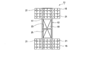
図7は本発明の実施の形態2に係るエネルギー吸収部材1の説明図であり、実施の形態1と同一部分及び対応する部分には同一の符号を付してある。本実施の形態のエネルギー吸収部材1が実施の形態1と異なる点は、実施の形態1のブラケット部材3、7は角形鋼管12によって構成されていたが、本実施の形態のブラケット部材3、7は、角形鋼管12が埋め込まれた鉄筋コンクリート部27を有する点である。
つまり、本実施の形態に係るエネルギー吸収部材1のブラケット部材3、7は、鉄筋コンクリートからなる鉄筋コンクリート部27を有し、該鉄筋コンクリート部27に角形鋼管12がその径の1.0倍以上埋め込まれている。そして、ブラケット部材3、7は鉄筋コンクリート部27を介して構造物に固定される。
[Embodiment 2]
FIG. 7 is an explanatory diagram of the
That is, the
本実施の形態の角形鋼管12にはコンクリートとの付着・一体化を図るための孔29を設けている。
孔29を設けることにより、コンクリートの施工性も向上し、品質の高いプレキャストブラケットにすることができる。
なお、角形鋼管12とコンクリートとの一体化を図る手段として、孔29を設けることに加えて、あるいは孔29を設ける代わりに、スタッド、鉄筋、厚板15などの部材を角形鋼管12に設置したり、角形鋼管12の下端に鋼管径よりも大きなエンドプレートを溶接するなどしたりしてもよい。
The
By providing the
As a means for integrating the
なお、上記の実施の形態においては、鉄筋コンクリートに角形鋼管12が埋め込まれる態様であったが、鉄筋コンクリートに代えてプレキャスト鉄筋コンクリートとしてもよい。
また、上記の例では、角形鋼管12が鉄筋コンクリートに埋め込まれる長さを角形鋼管12の径の1.0倍以上としたが、角形鋼管12の径の1.5倍以上とするのがより好ましい。
In the embodiment described above, the
In the above example, the length in which the
[実施の形態3]
図8は本発明の実施の形態3に係るエネルギー吸収部材1の説明図であり、実施の形態1と同一部分及び対応する部分には同一の符号を付してある。本実施の形態のエネルギー吸収部材1が実施の形態1と異なる点は、実施の形態1のダンパー部材11は角形鋼管12の外面側に設置されていたが、本実施の形態のダンパー部材11は角形鋼管12の内面側に設置した点である。
また、実施の形態1においては、厚板15と溝形鋼13との接合方法として、溝形鋼13の両端部のウェブ17を切除して、その切除した部分に厚板15を接合したが、本実施の形態においては、溝形鋼13の両端部のウェブを切除することなくウェブ部分に厚板15を接合している点においても相違する。
[Embodiment 3]
FIG. 8 is an explanatory diagram of the
In
本実施の形態のようにダンパー部材11を角形鋼管12の内面側に設置することにより、柱形が小さくなり、仕上げ材などの取り付けに有利となりコストメリットもある。
また、溝形鋼13の両端部のウェブを切除することなくウェブ部分に厚板15を接合することで、加工が容易となる。
By installing the
Moreover, a process becomes easy by joining the
実施の形態2に係るエネルギー吸収部材1を構造物に設置する場合の具体例を以下の実施例に示す。
The specific example in the case of installing the
この実施例は、RC(鉄筋コンクリート)のラーメン構造の梁の交点に、1辺80cmのプレキャスト柱を接合し、このプレキャスト柱にエネルギー吸収部材1を設置するものである。
プレキャスト柱に角形鋼管12(STKR□-500x12)を埋め込み、この角形鋼管12にダンパー部材11を1面せん断でボルト接合する。本実施例の場合、コンクリートとの一体化を増大させる手段として角形鋼管12に設ける孔はφ130とする。
ダンパー部材11は、コ−250x90x9x13の溝形鋼13のウェブ17の中央に縦48cm横21cmの開口を設け、低降伏点鋼19(LY225、厚さ6mm)を貼り、裏側から全周隅肉溶接を施す。この場合、低降伏点鋼19の短辺側の幅厚比は23.3となっている。低降伏点鋼19のパネルの中央にSS400のリブ25を設置し、溝形鋼13のフランジ23の内側と低降伏点鋼19に両面隅肉溶接する。
なお、低降伏点鋼19は、厚さ9mmのものを用いてもよく、この場合には低降伏点鋼19の短辺側の幅厚比は35となる。また、この場合には、低降伏点鋼19を接合するためにウェブ内側からも全周隅肉溶接を施すようにする。
In this embodiment, a precast column having a side of 80 cm is joined to an intersection of RC (steel reinforced concrete) rigid frame structures, and the
A square steel pipe 12 (STKR □ -500 × 12) is embedded in a precast column, and a
The
The low
1 エネルギー吸収部材 2 上側の梁 3 上側ブラケット部材
5 下側の梁 7 下側ブラケット部材 9 高力ボルト
11 ダンパー部材 12 角形鋼管 13 溝形鋼
15 厚板 17 ウェブ 19 低降伏点鋼
21 ボルト穴 23 フランジ 24 補剛板
25 リブ 27 鉄筋コンクリート部 29 孔
DESCRIPTION OF
Claims (8)
Priority Applications (1)
| Application Number | Priority Date | Filing Date | Title |
|---|---|---|---|
| JP2009127747A JP2010276080A (en) | 2009-05-27 | 2009-05-27 | Energy absorbing member and structure in which the energy absorbing member is installed |
Applications Claiming Priority (1)
| Application Number | Priority Date | Filing Date | Title |
|---|---|---|---|
| JP2009127747A JP2010276080A (en) | 2009-05-27 | 2009-05-27 | Energy absorbing member and structure in which the energy absorbing member is installed |
Publications (1)
| Publication Number | Publication Date |
|---|---|
| JP2010276080A true JP2010276080A (en) | 2010-12-09 |
Family
ID=43423228
Family Applications (1)
| Application Number | Title | Priority Date | Filing Date |
|---|---|---|---|
| JP2009127747A Pending JP2010276080A (en) | 2009-05-27 | 2009-05-27 | Energy absorbing member and structure in which the energy absorbing member is installed |
Country Status (1)
| Country | Link |
|---|---|
| JP (1) | JP2010276080A (en) |
Cited By (5)
| Publication number | Priority date | Publication date | Assignee | Title |
|---|---|---|---|---|
| KR102017546B1 (en) * | 2018-04-16 | 2019-09-03 | 주식회사 오케이건설 | Method and Structure for Reinforcing Seismic Resistance of Windows |
| CN112144688A (en) * | 2020-10-30 | 2020-12-29 | 中国地震局工程力学研究所 | Double-sided shearing type square steel tube damper and manufacturing method |
| CN113107105A (en) * | 2021-04-18 | 2021-07-13 | 无锡太湖学院 | Damper arrangement and use method of concrete structure with energy dissipation and shock absorption functions |
| CN113123481A (en) * | 2021-04-16 | 2021-07-16 | 无锡太湖学院 | Concrete structure based on energy dissipation and shock absorption and reinforcing method |
| JP2023004536A (en) * | 2021-06-28 | 2023-01-17 | Jfeシビル株式会社 | Stud-type steel damper |
Citations (7)
| Publication number | Priority date | Publication date | Assignee | Title |
|---|---|---|---|---|
| JPH10153013A (en) * | 1996-11-22 | 1998-06-09 | Nkk Corp | Aseismatic wall and its fitting structure |
| JP2002220941A (en) * | 2001-01-25 | 2002-08-09 | Nkk Corp | Vibration control framed structure |
| JP2003278401A (en) * | 2002-03-26 | 2003-10-02 | Takenaka Komuten Co Ltd | Column joint having energy absorbing member |
| JP2003313815A (en) * | 2002-04-19 | 2003-11-06 | Nippon Steel Corp | Rigid connecting structure between steel girder and steel pipe pier |
| JP2003321944A (en) * | 2002-04-30 | 2003-11-14 | Hazama Gumi Ltd | Aseismic damper |
| JP2006161846A (en) * | 2004-12-02 | 2006-06-22 | Nippon Steel Corp | Damping panel |
| JP2007186983A (en) * | 2005-12-15 | 2007-07-26 | Takenaka Komuten Co Ltd | Column joint structure such as reinforced concrete column |
-
2009
- 2009-05-27 JP JP2009127747A patent/JP2010276080A/en active Pending
Patent Citations (7)
| Publication number | Priority date | Publication date | Assignee | Title |
|---|---|---|---|---|
| JPH10153013A (en) * | 1996-11-22 | 1998-06-09 | Nkk Corp | Aseismatic wall and its fitting structure |
| JP2002220941A (en) * | 2001-01-25 | 2002-08-09 | Nkk Corp | Vibration control framed structure |
| JP2003278401A (en) * | 2002-03-26 | 2003-10-02 | Takenaka Komuten Co Ltd | Column joint having energy absorbing member |
| JP2003313815A (en) * | 2002-04-19 | 2003-11-06 | Nippon Steel Corp | Rigid connecting structure between steel girder and steel pipe pier |
| JP2003321944A (en) * | 2002-04-30 | 2003-11-14 | Hazama Gumi Ltd | Aseismic damper |
| JP2006161846A (en) * | 2004-12-02 | 2006-06-22 | Nippon Steel Corp | Damping panel |
| JP2007186983A (en) * | 2005-12-15 | 2007-07-26 | Takenaka Komuten Co Ltd | Column joint structure such as reinforced concrete column |
Cited By (8)
| Publication number | Priority date | Publication date | Assignee | Title |
|---|---|---|---|---|
| KR102017546B1 (en) * | 2018-04-16 | 2019-09-03 | 주식회사 오케이건설 | Method and Structure for Reinforcing Seismic Resistance of Windows |
| CN112144688A (en) * | 2020-10-30 | 2020-12-29 | 中国地震局工程力学研究所 | Double-sided shearing type square steel tube damper and manufacturing method |
| CN112144688B (en) * | 2020-10-30 | 2023-04-14 | 中国地震局工程力学研究所 | Double-sided shearing type square steel tube damper and manufacturing method |
| CN113123481A (en) * | 2021-04-16 | 2021-07-16 | 无锡太湖学院 | Concrete structure based on energy dissipation and shock absorption and reinforcing method |
| CN113107105A (en) * | 2021-04-18 | 2021-07-13 | 无锡太湖学院 | Damper arrangement and use method of concrete structure with energy dissipation and shock absorption functions |
| CN113107105B (en) * | 2021-04-18 | 2022-06-10 | 无锡太湖学院 | Damper with energy dissipation and shock absorption for concrete structure and arrangement and use method thereof |
| JP2023004536A (en) * | 2021-06-28 | 2023-01-17 | Jfeシビル株式会社 | Stud-type steel damper |
| JP7262518B2 (en) | 2021-06-28 | 2023-04-21 | Jfeシビル株式会社 | Stud type steel damper |
Similar Documents
| Publication | Publication Date | Title |
|---|---|---|
| JP4861067B2 (en) | Steel frame | |
| KR101263078B1 (en) | Connection metal fitting and building with the same | |
| JP6394239B2 (en) | Connecting pillar | |
| JP2001254436A (en) | Joining structure of steel column and steel beam | |
| JP2003261993A (en) | Column and beam coupling structure | |
| JP2010276080A (en) | Energy absorbing member and structure in which the energy absorbing member is installed | |
| JP4664997B2 (en) | Buildings with joint hardware | |
| JP2009047193A (en) | Damper device and structure | |
| JP5132503B2 (en) | Seismic structure and building | |
| KR102122028B1 (en) | Column type vibration isolation apparatus | |
| JP5405062B2 (en) | Vibration-damping studs using viscoelastic dampers and buckling-restrained braces | |
| JP3809536B2 (en) | Seismic wall structures in existing reinforced concrete buildings and steel reinforced concrete buildings | |
| JP5654060B2 (en) | Damper brace and damping structure | |
| JP2007277911A (en) | Structure of seismic response control column | |
| JP4181680B2 (en) | Damping brace damper, energy absorber used therefor, and design method thereof | |
| JP2602888Y2 (en) | Elasto-plastic damper | |
| JP5251933B2 (en) | Buildings with joint hardware | |
| JP2010121383A (en) | Seismic retrofitting method and building | |
| JP3271239B2 (en) | Steel shear wall | |
| JP6717636B2 (en) | Vibration control device | |
| JP5254767B2 (en) | Seismic structure, building with seismic structure, and repair method. | |
| JP2009161937A (en) | Damping frame | |
| JP5628601B2 (en) | Seismic reinforcement method for existing steel buildings | |
| JP5292881B2 (en) | Vibration control panel | |
| JP4411444B2 (en) | Shear panel type damper mounting structure to structure |
Legal Events
| Date | Code | Title | Description |
|---|---|---|---|
| A621 | Written request for application examination |
Free format text: JAPANESE INTERMEDIATE CODE: A621 Effective date: 20120113 |
|
| A977 | Report on retrieval |
Free format text: JAPANESE INTERMEDIATE CODE: A971007 Effective date: 20121127 |
|
| A131 | Notification of reasons for refusal |
Free format text: JAPANESE INTERMEDIATE CODE: A131 Effective date: 20121204 |
|
| A521 | Written amendment |
Free format text: JAPANESE INTERMEDIATE CODE: A523 Effective date: 20130130 |
|
| A711 | Notification of change in applicant |
Free format text: JAPANESE INTERMEDIATE CODE: A711 Effective date: 20130227 |
|
| A521 | Written amendment |
Free format text: JAPANESE INTERMEDIATE CODE: A821 Effective date: 20130301 |
|
| A131 | Notification of reasons for refusal |
Free format text: JAPANESE INTERMEDIATE CODE: A131 Effective date: 20130730 |
|
| A521 | Written amendment |
Free format text: JAPANESE INTERMEDIATE CODE: A523 Effective date: 20130927 |
|
| A02 | Decision of refusal |
Free format text: JAPANESE INTERMEDIATE CODE: A02 Effective date: 20140204 |