JP2010268564A - Ultrasonic actuator - Google Patents

Ultrasonic actuator Download PDF

Info

Publication number
JP2010268564A
JP2010268564A JP2009116556A JP2009116556A JP2010268564A JP 2010268564 A JP2010268564 A JP 2010268564A JP 2009116556 A JP2009116556 A JP 2009116556A JP 2009116556 A JP2009116556 A JP 2009116556A JP 2010268564 A JP2010268564 A JP 2010268564A
Authority
JP
Japan
Prior art keywords
state
detection
piezoelectric vibrator
protrusions
rotor
Prior art date
Legal status (The legal status is an assumption and is not a legal conclusion. Google has not performed a legal analysis and makes no representation as to the accuracy of the status listed.)
Granted
Application number
JP2009116556A
Other languages
Japanese (ja)
Other versions
JP5229098B2 (en
Inventor
Akira Kosaka
明 小坂
Takashi Matsuo
隆 松尾
Katsuichi Uratani
勝一 浦谷
Current Assignee (The listed assignees may be inaccurate. Google has not performed a legal analysis and makes no representation or warranty as to the accuracy of the list.)
Konica Minolta Opto Inc
Original Assignee
Konica Minolta Opto Inc
Priority date (The priority date is an assumption and is not a legal conclusion. Google has not performed a legal analysis and makes no representation as to the accuracy of the date listed.)
Filing date
Publication date
Application filed by Konica Minolta Opto Inc filed Critical Konica Minolta Opto Inc
Priority to JP2009116556A priority Critical patent/JP5229098B2/en
Publication of JP2010268564A publication Critical patent/JP2010268564A/en
Application granted granted Critical
Publication of JP5229098B2 publication Critical patent/JP5229098B2/en
Expired - Fee Related legal-status Critical Current
Anticipated expiration legal-status Critical

Links

Images

Landscapes

  • General Electrical Machinery Utilizing Piezoelectricity, Electrostriction Or Magnetostriction (AREA)

Abstract

<P>PROBLEM TO BE SOLVED: To provide an ultrasonic actuator that controls position, including a moving direction, of a moving body with high accuracy without increasing size and cost. <P>SOLUTION: In the ultrasonic actuator 100, a piezoelectric vibrator 2b includes: a driving state in which the moving body 1 is moved and all the projections are positioned in a first range; and a detection state in which some of the projections are positioned in a first range and the other projections are positioned in a second range. The detection state further includes a first detection state and a second detection state depending on the number of projections positioned in the first range. An operation part 17 calculates position information on the moving body 1 based on a change in the vibration state of the piezoelectric vibrator 2b caused when the moving body is moved. <P>COPYRIGHT: (C)2011,JPO&INPIT

Description

本発明は、圧電素子の振動により駆動する超音波アクチュエータに関する。   The present invention relates to an ultrasonic actuator that is driven by vibration of a piezoelectric element.

超音波アクチュエータは、圧電素子を有する圧電振動子を備えた固定部と移動体とが接触するよう構成され、圧電振動子が振動することで駆動する。具体的には、圧電振動子が振動することで固定部の表面に進行波が発生し、固定部はその波の頂点でのみ移動体と接することとなる。その波の頂点は楕円回転運動を行っていることから、固定部に突き動かされるように移動体が移動することとなる。超音波アクチュエータは、このような原理により駆動することから、駆動の際に固定部と移動体間に滑りが生じる可能性がある。したがって、移動体の移動量を制御することが困難であった。そこで、超音波アクチュエータにおいては、ロータリーエンコーダ等の位置検出装置を設ける等の方法により、移動体の移動量を制御していた。すなわち、位置検出装置により移動体の移動量を検出し、フィードバック制御により移動体の移動量や移動方向等を制御していた。しかし、ロータリーエンコーダを取り付けることで、超音波アクチュエータの組み込みスペースが増大するという問題があった。   The ultrasonic actuator is configured such that a fixed portion including a piezoelectric vibrator having a piezoelectric element and a moving body are in contact with each other, and is driven by the vibration of the piezoelectric vibrator. Specifically, a traveling wave is generated on the surface of the fixed part by the vibration of the piezoelectric vibrator, and the fixed part comes into contact with the moving body only at the top of the wave. Since the top of the wave is rotating elliptically, the moving body moves so as to be pushed by the fixed part. Since the ultrasonic actuator is driven according to such a principle, there is a possibility that slip occurs between the fixed portion and the moving body during driving. Therefore, it is difficult to control the moving amount of the moving body. Therefore, in the ultrasonic actuator, the moving amount of the moving body is controlled by a method such as providing a position detection device such as a rotary encoder. That is, the moving amount of the moving body is detected by the position detection device, and the moving amount and moving direction of the moving body are controlled by feedback control. However, attaching the rotary encoder has a problem that the space for installing the ultrasonic actuator increases.

この問題を解決するために、種々の方法が提案されている。例えば、特許文献1には、移動体に突起部等の不均一部分が形成された超音波アクチュエータが記載されている。この超音波アクチュエータは、圧電振動子に供給している駆動電流の波高値の包絡線を検出し、さらに電気的な信号処理を施すことで、移動体の移動量を検出し、移動量の制御を行っている。   In order to solve this problem, various methods have been proposed. For example, Patent Document 1 describes an ultrasonic actuator in which a non-uniform portion such as a protrusion is formed on a moving body. This ultrasonic actuator detects the peak value of the drive current supplied to the piezoelectric vibrator, and further performs electrical signal processing to detect the amount of movement of the moving body and control the amount of movement. It is carried out.

また、特許文献2には、振動子と移動体との接触部に不均質接触部が形成された超音波モータが記載されている。この超音波モータは、振動子に設けられた振動検出手段の検出信号と印加電圧との位相差の変動の周期を比較する等して得られる変動周期から、移動体の位置および回転数を検出する手段を有する。   Patent Document 2 describes an ultrasonic motor in which a heterogeneous contact portion is formed at a contact portion between a vibrator and a moving body. This ultrasonic motor detects the position and the number of rotations of the moving body from the fluctuation cycle obtained by comparing the cycle of fluctuation of the phase difference between the detection signal of the vibration detection means provided on the vibrator and the applied voltage. Means to do.

特許文献1および特許文献2に記載された発明によれば、エンコーダなどの移動体の位置等を検出するセンサなしに移動体の位置決めおよび回転数等を検出できる。   According to the inventions described in Patent Document 1 and Patent Document 2, it is possible to detect the positioning of the moving body, the number of rotations, and the like without a sensor that detects the position of the moving body such as an encoder.

特開平6−225550号公報JP-A-6-225550 特開平6−133570号公報JP-A-6-133570

しかし、特許文献1の超音波アクチュエータでは、圧電振動子の駆動電流の波高値変化が小さいため、正確な移動量の検出は難しく、高精度の位置制御は困難である。また、不均一部分の形状を、不均一部分以外の箇所と比べて大きく変化させることで、波高値変化を大きくすることは可能であるが、それにより駆動効率が低下するという新たな問題が生じる。また、特許文献2の超音波モータであっても、振動子と移動体とは面接触であることから、移動体の移動量が平均化されてしまい、高精度の検出は困難であるとの問題がある。   However, in the ultrasonic actuator of Patent Document 1, since the change in the crest value of the drive current of the piezoelectric vibrator is small, it is difficult to accurately detect the movement amount, and it is difficult to perform highly accurate position control. In addition, it is possible to increase the peak value change by changing the shape of the non-uniform part greatly compared with the part other than the non-uniform part, but this causes a new problem that the driving efficiency is lowered. . Further, even in the ultrasonic motor of Patent Document 2, since the vibrator and the moving body are in surface contact, the moving amount of the moving body is averaged, and it is difficult to detect with high accuracy. There's a problem.

本発明は、上述の事情に鑑みて為された発明であり、その目的は、大型化および高コスト化せずに、移動体の移動方向を含む位置制御を高精度に行うことができる超音波アクチュエータを提供することである。   The present invention has been made in view of the above-described circumstances, and an object of the present invention is an ultrasonic wave capable of performing position control including a moving direction of a moving body with high accuracy without increasing the size and cost. An actuator is provided.

本発明者は、種々検討した結果、上記目的は、以下の本発明により達成されることを見出した。すなわち、本発明に係る一態様に係る超音波アクチュエータは、電気信号が入力されることで振動する多層構造の圧電振動子と、前記圧電振動子に対して前記圧電振動子の積層方向側に位置する3つ以上の突起部とを有する振動体と、前記突起部と接触し、前記突起部に対して移動する移動体と、前記移動体の位置情報を算出する演算部とを備え、前記移動体は前記突起部と接触する面に、前記移動体の移動方向に沿って交互に複数形成された、構造的に互いに異なる第1の領域および第2の領域を有し、前記圧電振動子の振動状態は、前記移動体が移動することにより、前記突起部のすべてが第1の領域に位置する駆動状態と、前記突起部の一部が前記第1の領域に位置し、前記突起部の残りの突起部が前記第2の領域に位置する検出状態とがあり、さらに、前記検出状態においては、前記第1の領域に位置する前記突起部の数によって第1検出状態および第2検出状態があり、前記演算部は、前記移動体が移動することにより生じる、前記圧電振動子の振動状態の変化に基づいて、前記移動体の位置情報を算出する。   As a result of various studies, the present inventor has found that the above object is achieved by the present invention described below. That is, an ultrasonic actuator according to one aspect of the present invention includes a multilayered piezoelectric vibrator that vibrates when an electric signal is input, and is positioned on the side of the piezoelectric vibrator in the stacking direction with respect to the piezoelectric vibrator. A vibrating body having three or more projecting portions, a moving body that contacts the projecting portion and moves relative to the projecting portion, and an arithmetic unit that calculates position information of the moving body, The body has a first region and a second region that are structurally different from each other and are formed in a plurality in alternation along the moving direction of the moving body on a surface that contacts the protrusion, The vibration state includes a driving state in which all of the protrusions are located in the first region by moving the moving body, and a part of the protrusions are located in the first region. Detection state in which remaining protrusions are located in the second region Furthermore, in the detection state, there are a first detection state and a second detection state depending on the number of the protrusions located in the first region, and the arithmetic unit is configured by the moving body moving. Based on the generated change in the vibration state of the piezoelectric vibrator, position information of the moving body is calculated.

このように、超音波アクチュエータは、移動体の移動に伴う、圧電振動子の振動状態の変化に基づいて、移動体の位置情報を算出するので、その位置情報をもとに、高精度の位置制御が可能である。したがって、位置制御装置等を備える必要なく、位置制御が可能である超音波アクチュエータを実現できる。また、超音波アクチュエータにおいて、圧電振動子の振動状態は、突起部のすべてが第1の領域に位置する駆動状態、第1検出状態および第2検出状態を有し、この振動状態の変化に基づいて移動体の位置情報を算出するので、移動体の移動量だけでなく、移動方向も算出できる。   As described above, since the ultrasonic actuator calculates the position information of the moving body based on the change in the vibration state of the piezoelectric vibrator accompanying the movement of the moving body, a highly accurate position is calculated based on the position information. Control is possible. Therefore, it is possible to realize an ultrasonic actuator that can perform position control without the need for a position control device or the like. In the ultrasonic actuator, the vibration state of the piezoelectric vibrator has a drive state, a first detection state, and a second detection state in which all the protrusions are located in the first region, and is based on the change in the vibration state. Since the position information of the moving body is calculated, not only the moving amount of the moving body but also the moving direction can be calculated.

また、上述の超音波アクチュエータにおいて、前記突起部のそれぞれの間隔のうち、少なくとも1つは等間隔ではないように、前記突起部は配置され、かつ、前記第2の領域のそれぞれは等間隔に配置されていることが好ましい。   Further, in the above-described ultrasonic actuator, the protrusions are arranged such that at least one of the intervals of the protrusions is not equal, and the second regions are equally spaced. It is preferable that they are arranged.

これにより、移動体が移動する方向が異なると、駆動状態、第1検出状態および第2検出状態の変化の順序が異なる。したがって、超音波アクチュエータは、これら振動状態の変化に基づいて、移動体の移動方向を含む、移動体の位置情報を算出することができる。   Accordingly, when the moving direction of the moving body is different, the order of change of the driving state, the first detection state, and the second detection state is different. Therefore, the ultrasonic actuator can calculate the position information of the moving body including the moving direction of the moving body based on the change in the vibration state.

また、上述の超音波アクチュエータにおいて、前記突起部のそれぞれは、等間隔に配置され、かつ、前記第2の領域のそれぞれの間隔のうち、少なくとも1つは等間隔ではないように、前記第2の領域は配置されていることが好ましい。   Further, in the above-described ultrasonic actuator, the protrusions are arranged at equal intervals, and at least one of the intervals of the second regions is not equal. These regions are preferably arranged.

これにより、移動体が移動する方向が異なると、駆動状態、第1検出状態および第2検出状態の変化の順序が異なる。したがって、超音波アクチュエータは、これら振動状態の変化に基づいて、移動体の移動方向を含む、移動体の位置情報を算出することができる。   Accordingly, when the moving direction of the moving body is different, the order of change of the driving state, the first detection state, and the second detection state is different. Therefore, the ultrasonic actuator can calculate the position information of the moving body including the moving direction of the moving body based on the change in the vibration state.

また、上述の超音波アクチュエータにおいて、前記第2の領域は、前記移動体において前記突起部と接触する面に形成された溝であり、前記第1の領域は、該面における前記第2の領域以外の領域であることが好ましい。   Moreover, in the above-described ultrasonic actuator, the second region is a groove formed on a surface of the movable body that contacts the protrusion, and the first region is the second region on the surface. It is preferable that it is an area | region other than.

これにより、移動体が移動することで、圧電振動子の振動状態が変化する。また、溝および溝以外の箇所との境界付近に突起部が位置する場合にも振動状態が明確であるため、溝および溝以外の箇所の違いを正確に高精度に検出することができる。   Thereby, the vibration state of the piezoelectric vibrator changes as the moving body moves. In addition, since the vibration state is clear even when the protrusion is located near the boundary between the groove and a portion other than the groove, the difference between the groove and the portion other than the groove can be detected accurately and with high accuracy.

また、上述の超音波アクチュエータにおいて、前記振動体は、前記圧電振動子の振動状態を検出する振動状態検知電極をさらに有し、前記演算部は、前記振動状態検知電極により検出された前記圧電振動子の振動状態を用いて、前記移動体の位置情報を算出することが好ましい。   In the above-described ultrasonic actuator, the vibrating body further includes a vibration state detection electrode that detects a vibration state of the piezoelectric vibrator, and the calculation unit is configured to detect the piezoelectric vibration detected by the vibration state detection electrode. It is preferable to calculate the position information of the moving body using the vibration state of the child.

これにより、圧電振動子の振動状態を電気的に検出することができ、超音波アクチュエータが大型化、高コスト化せずに、高精度の位置制御が可能である。   As a result, the vibration state of the piezoelectric vibrator can be electrically detected, and high-accuracy position control can be performed without increasing the size and cost of the ultrasonic actuator.

また、上述の超音波アクチュエータにおいて、前記振動状態検知電極は、前記圧電振動子の層間に設置された内部電極であることが好ましい。   In the ultrasonic actuator described above, it is preferable that the vibration state detection electrode is an internal electrode installed between layers of the piezoelectric vibrator.

これにより、簡易な構成により、圧電振動子の振動状態を検出することができる。   Thereby, the vibration state of the piezoelectric vibrator can be detected with a simple configuration.

また、上述の超音波アクチュエータにおいて、前記演算部は、前記圧電振動子の駆動電圧に対する、前記振動状態検知電極により検出された振動検知電圧の位相に基づいて移動体の位置情報を算出することが好ましい。   In the ultrasonic actuator described above, the calculation unit may calculate position information of the moving body based on a phase of the vibration detection voltage detected by the vibration state detection electrode with respect to the drive voltage of the piezoelectric vibrator. preferable.

これより、圧電振動子の振動状態を正確かつ容易に検出することができる。   Thereby, the vibration state of the piezoelectric vibrator can be detected accurately and easily.

本発明によれば、大型化および高コスト化せずに、移動体の移動方向を含む位置制御を高精度に行う超音波アクチュエータを提供することができる。   ADVANTAGE OF THE INVENTION According to this invention, the ultrasonic actuator which performs position control including the moving direction of a moving body with high precision can be provided, without enlarging and costing.

本実施形態に係る超音波アクチュエータを用いた、レンズ駆動ユニットの構成について説明するための図である。It is a figure for demonstrating the structure of the lens drive unit using the ultrasonic actuator which concerns on this embodiment. 本実施形態に係る超音波アクチュエータの機械的な構成を説明するための図である。It is a figure for demonstrating the mechanical structure of the ultrasonic actuator which concerns on this embodiment. 本実施形態に係る超音波アクチュエータの電気的な構成を説明するための図である。It is a figure for demonstrating the electrical structure of the ultrasonic actuator which concerns on this embodiment. 本実施形態に係る振動体の外観を説明するための図であって、図4(A)は振動体の平面図であり、図4(B)は圧電振動子の駆動電極が設置された側の側面図であり、図4(C)は圧電振動子の検知信号取出し電極が設置された側の側面図である。FIG. 4A is a plan view of the vibrating body, and FIG. 4B is a side on which the drive electrode of the piezoelectric vibrator is installed, for explaining the appearance of the vibrating body according to the present embodiment. FIG. 4C is a side view of the side on which the detection signal extraction electrode of the piezoelectric vibrator is installed. 本実施形態に係る圧電振動子の各層における電極構成を示す断面図であって、図5(A)は第1の断面図であり、図5(B)は第2の断面図である。FIG. 5A is a cross-sectional view showing the electrode configuration in each layer of the piezoelectric vibrator according to the present embodiment, FIG. 5A is a first cross-sectional view, and FIG. 5B is a second cross-sectional view. 屈曲1次モードを示す図である。It is a figure which shows a bending primary mode. 本実施形態に係る突起部の回転を説明するための図であって、図7(A)は接触部の側面図であり、図7(B)は接触部の平面図である。FIG. 7A is a side view of the contact portion, and FIG. 7B is a plan view of the contact portion, illustrating the rotation of the protrusion according to the present embodiment. 本実施形態に係るロータと接触部との分解斜視図である。It is a disassembled perspective view of the rotor and contact part which concern on this embodiment. 本実施形態に係るロータにおける接触部と接する面の形状を説明する図である。It is a figure explaining the shape of the surface which contacts the contact part in the rotor which concerns on this embodiment. 薄板を備えたロータおよび接触部の要部拡大側面図である。It is a principal part enlarged side view of the rotor provided with the thin plate, and a contact part. 本実施形態に係る超音波アクチュエータにおける突起部と溝との位置関係を示す図であって、図11(A)は第1検出状態における突起部と溝との位置関係を示す図であり、図11(B)は第2検出状態における突起部と溝との位置関係を示す図である。FIG. 11A is a diagram illustrating a positional relationship between the protrusion and the groove in the ultrasonic actuator according to the present embodiment, and FIG. 11A is a diagram illustrating a positional relationship between the protrusion and the groove in the first detection state. 11B is a diagram illustrating a positional relationship between the protrusion and the groove in the second detection state. 振動検知電圧と駆動電圧の周波数との関係を示すグラフである。It is a graph which shows the relationship between a vibration detection voltage and the frequency of a drive voltage. 駆動電圧に対する振動検知電圧の位相と、駆動電圧の周波数との関係を示すグラフである。It is a graph which shows the relationship between the phase of the vibration detection voltage with respect to a drive voltage, and the frequency of a drive voltage. 駆動状態、第1検出状態および第2検出状態における、駆動電圧と振動検知電圧との波形について示したグラフである。It is the graph shown about the waveform of a drive voltage and a vibration detection voltage in a drive state, the 1st detection state, and the 2nd detection state. 本実施形態に係る超音波アクチュエータが駆動している場合の、駆動状態を基準とした位相差の時間変化を示すグラフであって、図15(A)はロータが右回転している場合における位相差の時間変化を示すグラフであり、図15(B)はロータが左回転している場合における位相差の時間変化を示すグラフである。FIG. 15A is a graph showing a temporal change in phase difference based on the driving state when the ultrasonic actuator according to the present embodiment is driven, and FIG. 15A shows the position when the rotor rotates clockwise. It is a graph which shows the time change of a phase difference, and FIG.15 (B) is a graph which shows the time change of a phase difference in case the rotor rotates counterclockwise. 本発明における他の実施形態に係る超音波アクチュエータの突起部と溝との位置関係を示す図であって、図16(A)は第1検出状態における突起部と溝との位置関係を示す図であり、図16(B)は第2検出状態における突起部と溝との位置関係を示す図である。It is a figure which shows the positional relationship of the projection part and groove | channel of the ultrasonic actuator which concerns on other embodiment in this invention, Comprising: FIG. 16 (A) is a figure which shows the positional relationship of the projection part and groove | channel in a 1st detection state. FIG. 16B is a diagram showing the positional relationship between the protrusion and the groove in the second detection state.

以下、本発明の実施の形態について図面に基づいて説明する。なお、各図において同一の符号を付した構成は、同一の構成であることを示し、その説明を省略する。   Hereinafter, embodiments of the present invention will be described with reference to the drawings. In addition, the structure which attached | subjected the same code | symbol in each figure shows that it is the same structure, The description is abbreviate | omitted.

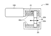
本発明の実施形態に係る超音波アクチュエータについて説明する。まず、本発明の実施形態に係る超音波アクチュエータを用いた、レンズ駆動ユニットの構成について説明する。図1は本実施形態に係る超音波アクチュエータを用いた、レンズ駆動ユニットの構成について説明するための図である。レンズ駆動ユニット300は、デジタルカメラやデジタルビデオカメラのAF、ズーム、DVDのピックアップレンズの収差補正の駆動などに用いられる。図1に示すように、本実施形態に係る超音波アクチュエータ100の回転軸と一体に結合されたリードスクリュー21に一部が螺合されたレンズ支持部22bと、レンズ支持部22bにより支持されたレンズ22と、レンズ22の移動を制御する、リードスクリュー21と平行に設置された2本のガイドレール22aと、これらを覆うケース23と、超音波アクチュエータ100とを備えて構成される。なお、図1においては、超音波アクチュエータ100の電気的構成部分については、図示を省略している。   An ultrasonic actuator according to an embodiment of the present invention will be described. First, a configuration of a lens driving unit using the ultrasonic actuator according to the embodiment of the present invention will be described. FIG. 1 is a diagram for explaining a configuration of a lens driving unit using the ultrasonic actuator according to the present embodiment. The lens driving unit 300 is used for AF and zooming of digital cameras and digital video cameras, and driving of aberration correction of a pickup lens of a DVD. As shown in FIG. 1, a lens support portion 22 b that is partially screwed with a lead screw 21 that is integrally coupled to the rotation shaft of the ultrasonic actuator 100 according to the present embodiment, and is supported by the lens support portion 22 b. The lens 22 includes two guide rails 22 a that are installed in parallel with the lead screw 21 to control the movement of the lens 22, a case 23 that covers these guide rails 22, and the ultrasonic actuator 100. In FIG. 1, the electrical components of the ultrasonic actuator 100 are not shown.

具体的には、レンズ22の外周部を支持しているレンズ支持部22bには貫通孔が形成され、その貫通孔にはガイドレール22aが貫通されていて、レンズ支持部22bはガイドレール22aに沿った方向のみ可動である。また、レンズ支持部22bはリードスクリュー21と螺合しており、リードスクリュー21がその軸を中心として回転することで、レンズ支持部22bがガイドレール22aに沿って駆動される。   Specifically, a through hole is formed in the lens support portion 22b that supports the outer peripheral portion of the lens 22, and a guide rail 22a is passed through the through hole, and the lens support portion 22b is connected to the guide rail 22a. It is movable only along the direction. The lens support portion 22b is screwed with the lead screw 21, and the lens support portion 22b is driven along the guide rail 22a as the lead screw 21 rotates about its axis.

このような、レンズ駆動ユニット300において、超音波アクチュエータ100が駆動することで、リードスクリュー21が右回転または左回転し、それにより、レンズ22と一体であるレンズ支持部22bが図1において左右方向に駆動する。つまり、レンズ駆動ユニット300は、直動レンズ送り機構を構成している。   In such a lens driving unit 300, when the ultrasonic actuator 100 is driven, the lead screw 21 is rotated clockwise or counterclockwise, whereby the lens support portion 22b integrated with the lens 22 is moved in the horizontal direction in FIG. To drive. That is, the lens driving unit 300 constitutes a linear movement lens feed mechanism.

このように、本実施形態に係る超音波アクチュエータ100は、例えばレンズ駆動ユニット300に用いられるが、これに限定されるわけではなく、他にも様々な用途に用いられている。   As described above, the ultrasonic actuator 100 according to the present embodiment is used in, for example, the lens driving unit 300, but is not limited thereto, and is used in various other applications.

次に、本実施形態に係る超音波アクチュエータの機械的な構成について説明する。図2は本実施形態に係る超音波アクチュエータの機械的な構成を説明するための図である。なお、図2においては、本実施形態に係る超音波アクチュエータの電気的な構成については、図示を省略している。図2に示すように、本発明の実施形態に係る超音波アクチュエータ100は、移動体であるロータ1と、ロータ1と接触する突起部2cを有する接触部2aおよび圧電振動子2bを有する振動体(ステータ)2と、振動体2の端部に設置された錘部5と、ロータ1の回転中心にロータ1と一体に設置された回転軸3と、回転軸3の軸受け27と、これらを覆うケース7と、ケース7の底面と振動体2とに接続され、振動体2をロータ1へと所定の付勢力で押し付けるバネ等の弾性体である加圧部6と、ケース7と接続された支持フレーム24と、支持フレーム24を貫通するように設置されたキャップ26と、キャップ26に形成された窪み26aに回転自在に嵌り込む球体である軸受け25とを備えて構成されている。   Next, the mechanical configuration of the ultrasonic actuator according to this embodiment will be described. FIG. 2 is a diagram for explaining the mechanical configuration of the ultrasonic actuator according to the present embodiment. In FIG. 2, the electrical configuration of the ultrasonic actuator according to this embodiment is not shown. As shown in FIG. 2, the ultrasonic actuator 100 according to the embodiment of the present invention includes a rotor 1 that is a moving body, a contact portion 2 a that has a protrusion 2 c that contacts the rotor 1, and a vibration body that includes a piezoelectric vibrator 2 b. (Stator) 2, weight 5 installed at the end of vibrating body 2, rotary shaft 3 installed integrally with rotor 1 at the center of rotation of rotor 1, bearing 27 of rotary shaft 3, and The case 7 is connected to the case 7 to be covered, the pressure unit 6 that is connected to the bottom surface of the case 7 and the vibrating body 2 and is an elastic body such as a spring that presses the vibrating body 2 against the rotor 1 with a predetermined urging force. The support frame 24, a cap 26 installed so as to penetrate the support frame 24, and a bearing 25 which is a spherical body that is rotatably fitted in a recess 26 a formed in the cap 26.

ロータ1は円板状である。回転軸3は、ロータ1の中心であって、前記円板の面に垂直方向に伸びるように配置されている。回転軸3はロータ1に一体的、または、かしめなどによる結合により構成されている。振動体2は、回転軸3を中心とする円板状の接触部2aおよび接触部2aに接合された圧電振動子2bとを備えて構成される。接触部2aは突起部2cを有していて、突起部2cがロータ1と接触している。突起部2cとロータ1との摩擦力によりロータ1が駆動することから、突起部2cを含む接触部2aは、例えば、アルミナ、ジルコニア等のセラミックス、超硬合金等の耐摩耗性の高い材料を用いればよい。なお、接触部2aは、例えばエポキシ等の剛性が高く、接着力が強い接着剤を用いて圧電振動子2bに固定されることとすればよい。圧電振動子2bは、圧電特性を示す圧電薄板と内部電極とが交互に積層されて構成されている。圧電振動子2bは製造のしやすさを考慮すると、直方体形状が好ましい。圧電薄板としては、例えばPZT(チタン酸ジルコニウム酸鉛)等からなる圧電セラミックス等の圧電素子の薄板を用いればよい。そして、内部電極を介して所定の電気信号が圧電振動子2bに送られることにより、圧電振動子2bは振動する。その振動により、圧電振動子2bに接続された接触部2aが振動し、ロータ1に接触している略球面を有する突起部2cも振動する。軸受け27は、回転軸3を回転自在に軸支する。具体的には、軸受け27により回転軸3はラジアル方向について支持されている。圧電振動子2bにおいて、接触部2aと接合している端部とは反対の端部に錘部5が設置されている。錘部5が設置されることで、振動体2の振動バランスが向上する。また、錘部5を設置することで、圧電振動子2bの振動の節の位置が錘部5側に移動するため、突起部2cの振動を大きくすることができる。例えば、錘部5は、比重の高いタングステンや、銅や鉄系のタングステン合金などとすればよい。   The rotor 1 has a disk shape. The rotating shaft 3 is the center of the rotor 1 and is disposed so as to extend in a direction perpendicular to the surface of the disk. The rotating shaft 3 is configured integrally with the rotor 1 or by coupling by caulking or the like. The vibrating body 2 includes a disk-shaped contact portion 2a centered on the rotation shaft 3 and a piezoelectric vibrator 2b joined to the contact portion 2a. The contact portion 2 a has a protrusion 2 c, and the protrusion 2 c is in contact with the rotor 1. Since the rotor 1 is driven by the frictional force between the protrusion 2c and the rotor 1, the contact portion 2a including the protrusion 2c is made of a material having high wear resistance such as ceramics such as alumina and zirconia, cemented carbide, and the like. Use it. In addition, the contact part 2a should just be fixed to the piezoelectric vibrator 2b using the adhesive agent with high rigidity, such as an epoxy, for example, and strong adhesive force. The piezoelectric vibrator 2b is configured by alternately laminating piezoelectric thin plates exhibiting piezoelectric characteristics and internal electrodes. In consideration of ease of manufacture, the piezoelectric vibrator 2b preferably has a rectangular parallelepiped shape. As the piezoelectric thin plate, for example, a thin plate of a piezoelectric element such as a piezoelectric ceramic made of PZT (lead zirconate titanate) or the like may be used. The piezoelectric vibrator 2b vibrates by sending a predetermined electric signal to the piezoelectric vibrator 2b via the internal electrode. Due to the vibration, the contact portion 2a connected to the piezoelectric vibrator 2b vibrates, and the projection portion 2c having a substantially spherical surface in contact with the rotor 1 also vibrates. The bearing 27 rotatably supports the rotary shaft 3. Specifically, the rotary shaft 3 is supported by the bearing 27 in the radial direction. In the piezoelectric vibrator 2b, the weight part 5 is installed at the end opposite to the end joined to the contact part 2a. By installing the weight portion 5, the vibration balance of the vibrating body 2 is improved. Moreover, since the position of the vibration node of the piezoelectric vibrator 2b moves to the weight part 5 side by installing the weight part 5, the vibration of the protrusion part 2c can be increased. For example, the weight portion 5 may be tungsten having a high specific gravity, copper, an iron-based tungsten alloy, or the like.

ロータ1と、振動体2と、回転軸3と、軸受け27と、錘部5と、加圧部6とはケース7内に配置されている。なお、回転軸3はケース7内から外部に突出している。また、軸受け27の一部はケース7の外部に露呈している。振動体2はケース7に対して回転が規制され、ケース7の底面からロータ1方向に加圧部6により押圧されている。それにより、接触部2aはロータ1と高い圧力をかけられた状態で接触している。支持フレーム24は回転軸3が突出する側のケース7の端面に設置されていて、ケース7から突出された回転軸3は、支持フレーム24内へと伸びている。回転軸3の端面は凹面となっており、支持フレーム24に設置されたキャップ26の窪み26aに嵌り込んだ球体である軸受け25がその凹面に嵌り込むように配置され、回転軸3は回転自在に軸受け25に軸支される。具体的には、軸受け25により回転軸3はラジアルおよびスラスト方向について支持されている。キャップ26は支持フレーム24と螺合して貫通している。つまり、支持フレーム24およびキャップ26はねじ切りされていて、キャップ26を締めるあるいは緩めることで、回転軸3に沿った方向へのキャップ26の位置を調整できる。加圧部6により振動体2がロータ1に押し付けられていることから、ロータ1に結合された回転軸3は軸受け25からの反力を受けるが、その反力は回転軸3の回転中心で受けることになるため、回転軸3と球体である軸受け25との摩擦ロスを最小限に抑えることができる。超音波アクチュエータ100の作製時において、キャップ26の位置を調整して、振動体2およびロータ1間の押圧力を調整すればよい。そして、調整が完了すれば、接着することでキャップ26の位置を固定すればよい。このようにすることで、振動体2はケース7に対して回転が規制されながら、ロータ1との軸心が位置決めされ、保持される。   The rotor 1, the vibrating body 2, the rotating shaft 3, the bearing 27, the weight portion 5, and the pressurizing portion 6 are disposed in the case 7. The rotating shaft 3 protrudes from the inside of the case 7 to the outside. A part of the bearing 27 is exposed to the outside of the case 7. The vibrating body 2 is restricted from rotating with respect to the case 7, and is pressed from the bottom surface of the case 7 toward the rotor 1 by the pressurizing unit 6. Thereby, the contact part 2a is in contact with the rotor 1 in a state where high pressure is applied. The support frame 24 is installed on the end surface of the case 7 on the side from which the rotary shaft 3 protrudes, and the rotary shaft 3 protruding from the case 7 extends into the support frame 24. The end surface of the rotating shaft 3 is a concave surface, and a bearing 25 that is a sphere fitted in a recess 26a of a cap 26 installed on the support frame 24 is disposed so as to fit in the concave surface, and the rotating shaft 3 is rotatable. Is supported by the bearing 25. Specifically, the rotary shaft 3 is supported by the bearing 25 in the radial and thrust directions. The cap 26 is threadedly engaged with the support frame 24 and penetrates. That is, the support frame 24 and the cap 26 are threaded, and the position of the cap 26 in the direction along the rotation shaft 3 can be adjusted by tightening or loosening the cap 26. Since the vibrating body 2 is pressed against the rotor 1 by the pressurizing unit 6, the rotating shaft 3 coupled to the rotor 1 receives a reaction force from the bearing 25, but the reaction force is at the center of rotation of the rotating shaft 3. Therefore, the friction loss between the rotating shaft 3 and the bearing 25 which is a sphere can be minimized. When manufacturing the ultrasonic actuator 100, the position of the cap 26 may be adjusted to adjust the pressing force between the vibrating body 2 and the rotor 1. And if adjustment is completed, the position of the cap 26 should just be fixed by adhere | attaching. By doing in this way, while the rotation of the vibrating body 2 is restricted with respect to the case 7, the axis center with the rotor 1 is positioned and held.

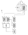
次に、本実施形態に係る超音波アクチュエータの電気的構成について説明する。図3は本実施形態に係る超音波アクチュエータの電気的な構成を説明するための図である。図3に示すように、本実施形態に係る超音波アクチュエータ100は、図2に示した以外に、制御部11と、駆動電圧生成部12と、駆動電流生成部13と、振動状態検知電極14と、検知電圧変換部15と、駆動電圧変換部16と、演算部17とを備えて構成される。なお、図3において、図2において示した機械的構成については、電気的構成の説明について必要な部材を示し、これら以外は図示を省略する。なお、制御部11および演算部17は例えば、マイクロプロセッサにより実現される。また、駆動電圧生成部12、駆動電流生成部13、検知電圧変換部15および駆動電圧変換部16は、例えば、抵抗、コンデンサ、コイル、トランジスタ等の電子素子が組み合わされて構成される。   Next, the electrical configuration of the ultrasonic actuator according to this embodiment will be described. FIG. 3 is a diagram for explaining the electrical configuration of the ultrasonic actuator according to the present embodiment. As shown in FIG. 3, the ultrasonic actuator 100 according to the present embodiment has a control unit 11, a drive voltage generation unit 12, a drive current generation unit 13, and a vibration state detection electrode 14 in addition to those shown in FIG. 2. And a detection voltage conversion unit 15, a drive voltage conversion unit 16, and a calculation unit 17. In FIG. 3, the mechanical configuration shown in FIG. 2 shows members necessary for the description of the electrical configuration, and illustration of the other components is omitted. In addition, the control part 11 and the calculating part 17 are implement | achieved by the microprocessor, for example. The drive voltage generation unit 12, the drive current generation unit 13, the detection voltage conversion unit 15, and the drive voltage conversion unit 16 are configured by combining electronic elements such as resistors, capacitors, coils, and transistors, for example.

制御部11は、例えば、図示されていない記憶素子に記憶された制御プログラムを読み込み、超音波アクチュエータ100の全体制御を行うものである。制御部11は、ロータ1が回転(移動)するよう電気信号である駆動信号を発生させる。具体的には、駆動信号が接触部2aの図示されていない突起部2cに楕円回転運動を生じさせるように圧電振動子2bを振動させることで、突起部2cにより突き動かされるように、回転軸3を中心軸としてロータ1が回転する。   For example, the control unit 11 reads a control program stored in a storage element (not shown) and performs overall control of the ultrasonic actuator 100. The controller 11 generates a drive signal that is an electrical signal so that the rotor 1 rotates (moves). Specifically, the rotation shaft is driven so that the drive signal is oscillated by the protrusion 2c by vibrating the piezoelectric vibrator 2b so that the protrusion 2c (not shown) of the contact portion 2a causes an elliptical rotational motion. The rotor 1 rotates about 3 as a central axis.

駆動電圧生成部12は、制御部11により指示された前記駆動信号に応じた駆動電圧を発生させる。また、圧電振動子2bの駆動制御は電流で行うことから、駆動電流生成部13では、前記駆動電圧に基づいた駆動電流を生成する。駆動電流生成部13により生成された駆動電流は、駆動電流生成部13から出力され、圧電振動子2bに入力される。   The drive voltage generation unit 12 generates a drive voltage according to the drive signal instructed by the control unit 11. In addition, since the drive control of the piezoelectric vibrator 2b is performed by a current, the drive current generation unit 13 generates a drive current based on the drive voltage. The drive current generated by the drive current generator 13 is output from the drive current generator 13 and input to the piezoelectric vibrator 2b.

振動状態検知電極14は、振動体2に備えられ、圧電振動子2bの振動状態を示す振動検知電圧を検知する電極である。具体的に圧電振動子2bが振動することで、振動状態検知電極14から、圧電振動子2bの振動状態を示す信号である電圧(振動検知電圧)が出力される。より具体的には、振動状態検知電極14は、圧電振動子2b内部に設置された電極である。それにより、振動状態検知電極14から出力される振動検知電圧により、圧電振動子2bの振動状態を直接検出することができ、高精度の検出が可能である。   The vibration state detection electrode 14 is an electrode that is provided in the vibration body 2 and detects a vibration detection voltage indicating the vibration state of the piezoelectric vibrator 2b. Specifically, when the piezoelectric vibrator 2b vibrates, the vibration state detection electrode 14 outputs a voltage (vibration detection voltage) that is a signal indicating the vibration state of the piezoelectric vibrator 2b. More specifically, the vibration state detection electrode 14 is an electrode installed inside the piezoelectric vibrator 2b. Thus, the vibration state of the piezoelectric vibrator 2b can be directly detected by the vibration detection voltage output from the vibration state detection electrode 14, and high-precision detection is possible.

検知電圧変換部15は振動状態検知電極14から出力された振動検知電圧をパルス信号に変換して演算部17に入力する。また、駆動電圧変換部16は駆動電圧生成部12で生成された駆動電圧をパルス信号に変換して、演算部17に入力する。このように、パルス信号に変換することにより、演算処理が容易になる。   The detection voltage conversion unit 15 converts the vibration detection voltage output from the vibration state detection electrode 14 into a pulse signal and inputs the pulse signal to the calculation unit 17. The drive voltage conversion unit 16 converts the drive voltage generated by the drive voltage generation unit 12 into a pulse signal and inputs the pulse signal to the calculation unit 17. As described above, the arithmetic processing is facilitated by converting the pulse signal.

演算部17は、検知電圧変換部15からの振動検知電圧および駆動電圧変換部16からの駆動電圧を対比して、駆動電圧に対する振動検知電圧の位相を算出する。演算部17は、算出した位相に基づきロータ1の移動量や回転方向等の位置情報を算出して、制御部11に指示する。制御部11では演算部17から得た位置情報を考慮して駆動信号を作成する。なお、位置情報とは、ロータ1の移動量や位置や回転方向等の、演算部17により算出した情報である。   The calculation unit 17 compares the vibration detection voltage from the detection voltage conversion unit 15 and the drive voltage from the drive voltage conversion unit 16 to calculate the phase of the vibration detection voltage with respect to the drive voltage. The calculation unit 17 calculates position information such as the movement amount and rotation direction of the rotor 1 based on the calculated phase, and instructs the control unit 11. The control unit 11 creates a drive signal in consideration of the position information obtained from the calculation unit 17. The position information is information calculated by the calculation unit 17 such as the movement amount, position, and rotation direction of the rotor 1.

次に、振動体2の構成について説明する。図4は本実施形態に係る振動体の外観を説明するための図であって、図4(A)は振動体の平面図であり、図4(B)は圧電振動子の駆動電極が設置された側の側面図であり、図4(C)は圧電振動子の検知信号取出し電極が設置された側の側面図である。図4(A)〜図4(C)に示すように、振動体2は突起部2c−1、2c−2、2c−3が設置された円形の接触部2aと圧電薄板が内部電極を介して積層された構成の圧電振動子2bを備えている。例えば、図4(A)に示すように、突起部2cは略球面を有し、接触部2aの中心軸に対して同心円上に3つ設置されている。なお、これら突起部2c−1、2c−2、2c−3は等間隔とならないように設置されている。また、突起部2c−1、2c−2、2c−3は、圧電振動子2bの積層方向側に位置している。例えば、2c−2および2c−3は接触部2aの中心を基準として120度離れた配置であり、2c−1および2c−2は115度離れた配置であり、2c−3および2c−1は125度離れた配置である。これら突起部2c−1、2c−2、2c−3の各頂点がロータ1に接触している。また、図4(B)、図4(C)に示すように、圧電振動子2bの積層された各内部電極に信号を入力あるいは信号を出力するための駆動電極2b−1、2b−2、2b−3、2b−4、検知信号取出し電極2b−5、接地電極2b−6が圧電振動子2bの各側面に設置されている。これら、駆動電極2b−1、2b−2、2b−3、2b−4、検知信号取出し電極2b−5、接地電極2b−6には、図示していないがリード線やフレキ等がハンダや導電性接着剤等により接合され、信号を送受信する。   Next, the configuration of the vibrating body 2 will be described. 4A and 4B are views for explaining the appearance of the vibrating body according to the present embodiment. FIG. 4A is a plan view of the vibrating body, and FIG. FIG. 4C is a side view of the side where the detection signal extraction electrode of the piezoelectric vibrator is installed. As shown in FIGS. 4A to 4C, the vibrating body 2 includes a circular contact portion 2a provided with projections 2c-1, 2c-2, and 2c-3, and a piezoelectric thin plate via an internal electrode. A piezoelectric vibrator 2b having a laminated structure is provided. For example, as shown in FIG. 4A, the protrusions 2c have a substantially spherical surface, and are provided on three concentric circles with respect to the central axis of the contact portion 2a. In addition, these protrusion parts 2c-1, 2c-2, 2c-3 are installed so that it may not become equal intervals. Further, the protrusions 2c-1, 2c-2, and 2c-3 are located on the stacking direction side of the piezoelectric vibrator 2b. For example, 2c-2 and 2c-3 are arranged 120 degrees apart from the center of the contact portion 2a, 2c-1 and 2c-2 are arranged 115 degrees apart, and 2c-3 and 2c-1 are The arrangement is 125 degrees apart. Each vertex of these protrusions 2c-1, 2c-2, 2c-3 is in contact with the rotor 1. Also, as shown in FIGS. 4B and 4C, drive electrodes 2b-1, 2b-2 for inputting or outputting signals to the internal electrodes stacked on the piezoelectric vibrator 2b, 2b-3, 2b-4, a detection signal extraction electrode 2b-5, and a ground electrode 2b-6 are installed on each side surface of the piezoelectric vibrator 2b. Although not shown, the drive electrodes 2b-1, 2b-2, 2b-3, 2b-4, the detection signal extraction electrode 2b-5, and the ground electrode 2b-6 are not shown in the figure. The signal is transmitted and received by bonding with a conductive adhesive or the like.

図5は本実施形態に係る圧電振動子の各層における電極構成を示す断面図であって、図5(A)は第1の断面図であり、図5(B)は第2の断面図である。圧電振動子2bは図5(A)および図5(B)で示される各内部電極2d〜2gおよび振動状態検知電極14が形成された圧電薄板20と、内部電極2hが形成された圧電薄板20とが交互に積層された多層構造である。つまり、内部電極2d〜2gおよび振動状態検知電極14を有する内部電極の層と、内部電極2hを有する内部電極の層とが交互に積層され、それらの内部電極の層の間に圧電薄板20が挿入されている。なお、これら内部電極2d〜2gおよび振動状態検知電極14は圧電薄板20に銀パラジウムなどを印刷することで形成される。内部電極2d〜2gは、それぞれ圧電薄板20の各角付近に形成されている。   FIG. 5 is a cross-sectional view showing the electrode configuration in each layer of the piezoelectric vibrator according to this embodiment. FIG. 5 (A) is a first cross-sectional view, and FIG. 5 (B) is a second cross-sectional view. is there. The piezoelectric vibrator 2b includes a piezoelectric thin plate 20 on which the internal electrodes 2d to 2g and the vibration state detection electrode 14 shown in FIGS. 5A and 5B are formed, and a piezoelectric thin plate 20 on which the internal electrode 2h is formed. Is a multilayer structure in which and are alternately stacked. That is, the internal electrode layer having the internal electrodes 2d to 2g and the vibration state detection electrode 14 and the internal electrode layer having the internal electrode 2h are alternately stacked, and the piezoelectric thin plate 20 is interposed between the internal electrode layers. Has been inserted. The internal electrodes 2d to 2g and the vibration state detection electrode 14 are formed by printing silver palladium or the like on the piezoelectric thin plate 20. The internal electrodes 2d to 2g are formed near each corner of the piezoelectric thin plate 20, respectively.

また、圧電振動子2bが、端面が略正方形である略四角柱形状である場合は、圧電振動子2bの断面は略正方形であり、その正方形の1辺の中央に振動状態検知電極14を設置することが好ましい。つまり、圧電薄板20が略正方形であり、1辺の中央に振動状態検知電極14を設置すればよい。それにより、圧電振動子2bの振動が顕著に現れる箇所、すなわち振幅が大きい箇所に振動状態検知電極14を設置することになるので、その振動成分を多く含む振動検知電圧値を得ることができ、より正確な圧電振動子の振動状態の検出が可能となる。   When the piezoelectric vibrator 2b has a substantially quadrangular prism shape whose end face is substantially square, the cross section of the piezoelectric vibrator 2b is substantially square, and the vibration state detection electrode 14 is installed at the center of one side of the square. It is preferable to do. That is, the piezoelectric thin plate 20 is substantially square, and the vibration state detection electrode 14 may be installed at the center of one side. Thereby, since the vibration state detection electrode 14 is installed at a place where the vibration of the piezoelectric vibrator 2b appears prominently, that is, a place where the amplitude is large, it is possible to obtain a vibration detection voltage value including a lot of vibration components, It is possible to detect the vibration state of the piezoelectric vibrator more accurately.

内部電極2hは、圧電薄板20の略全面に形成されている。そして、これら内部電極2d、2e、2f、2gは、駆動電極2b−1、2b−2、2b−3、2b−4とそれぞれ接続されている。また、内部電極である振動状態検知電極14は、検知信号取出し電極2b−5と接続されている。また、内部電極2hは接地電極2b−6と接続されている。なお、駆動電極2b−1、2b−2、2b−3、2b−4、検知信号取出し電極2b−5、接地電極2b−6は、例えば銀や金等をスクリーン印刷や蒸着等で形成すればよい。また、駆動電極2b−1、2b−2、2b−3、2b−4は、駆動電流生成部13と接続され、検知信号取出し電極2b−5は位相比較部12と接続され、接地電極2b−6は接地されている。上記接続および接地については、図示していないが、リード線やFPC(フレキシブルプリント配線基板)等を介して行われる。なお、圧電薄板20が圧電特性を示すためには、これらに所定の分極処理を行っておく必要がある。   The internal electrode 2h is formed on substantially the entire surface of the piezoelectric thin plate 20. The internal electrodes 2d, 2e, 2f, and 2g are connected to the drive electrodes 2b-1, 2b-2, 2b-3, and 2b-4, respectively. In addition, the vibration state detection electrode 14 which is an internal electrode is connected to the detection signal extraction electrode 2b-5. The internal electrode 2h is connected to the ground electrode 2b-6. The drive electrodes 2b-1, 2b-2, 2b-3, 2b-4, the detection signal extraction electrode 2b-5, and the ground electrode 2b-6 may be formed by, for example, silver or gold by screen printing or vapor deposition. Good. The drive electrodes 2b-1, 2b-2, 2b-3, 2b-4 are connected to the drive current generator 13, the detection signal extraction electrode 2b-5 is connected to the phase comparator 12, and the ground electrode 2b- 6 is grounded. The connection and grounding are not shown, but are performed via lead wires, FPC (flexible printed wiring board), or the like. In order for the piezoelectric thin plate 20 to exhibit piezoelectric characteristics, it is necessary to perform predetermined polarization processing on these.

次に、このような、圧電振動子2bの振動およびそれによる突起部2c−1〜2c−3の振動について説明する。図6は屈曲1次モードを示す図である。また、図7は本実施形態に係る突起部の回転を説明するための図であって、図7(A)は接触部の側面図であり、図7(B)は接触部の平面図である。上述のように、圧電振動子2bにおいて、駆動電極2b−1、2b−2、2b−4、2b−3に高周波駆動信号(駆動電流)を、それぞれ位相を90度ずらして印加すると、内部電極2d、2e、2g、2fの各領域が90度位相のずれた伸縮振動を行う。駆動信号の周波数を共振周波数に近づけると、圧電振動子2bには、屈曲1次モードが励起される。ここで、屈曲1次モードが励起された場合に、直方体である圧電振動子2bは、図6に示すように、2箇所の節Pにより1次の曲げ変形運動を左右に繰り返す。本実施形態に係る超音波アクチュエータ100の場合は、各駆動電極2b−1、2b−2、2b−4、2b−3に印加される高周波駆動信号は、それぞれ90度位相がずれていることから、圧電振動子2bには各内部電極2d、2e、2g、2fにより屈曲1次モードによる振動がずれながら生じる。それにより、接触部2aと接合された圧電振動子2bの先端は公転運動(首振り振動)を行う。そして、圧電振動子2bがこのような動きをすることで、圧電振動子2b上に設置された接触部2aの突起部2c−1〜2c−3は、図7(A)および図7(B)において、矢印で示したような楕円振動を行う。上述のように、ロータ1は接触部2aに押圧されている。したがって、ロータ1と突起部2c−1〜2c−3との間の摩擦係数は大きい。そのため、各突起部2c−1〜2c−3が上述したように、楕円振動を行うことで、ロータ1は突起部2c−1〜2c−3に突き動かされるように、回転軸3を中心に回転を行う。   Next, the vibration of the piezoelectric vibrator 2b and the vibration of the protrusions 2c-1 to 2c-3 due to the vibration will be described. FIG. 6 is a diagram showing a bending primary mode. FIG. 7 is a view for explaining the rotation of the protrusion according to the present embodiment, FIG. 7A is a side view of the contact portion, and FIG. 7B is a plan view of the contact portion. is there. As described above, in the piezoelectric vibrator 2b, when a high frequency drive signal (drive current) is applied to the drive electrodes 2b-1, 2b-2, 2b-4, 2b-3 with a phase shifted by 90 degrees, the internal electrodes The 2d, 2e, 2g, and 2f regions perform stretching vibrations that are 90 degrees out of phase. When the frequency of the drive signal is brought close to the resonance frequency, the bending primary mode is excited in the piezoelectric vibrator 2b. Here, when the bending primary mode is excited, the piezoelectric vibrator 2b, which is a rectangular parallelepiped, repeats the primary bending deformation motion to the left and right by two nodes P as shown in FIG. In the case of the ultrasonic actuator 100 according to the present embodiment, the high frequency drive signals applied to the drive electrodes 2b-1, 2b-2, 2b-4, and 2b-3 are each 90 degrees out of phase. In the piezoelectric vibrator 2b, vibrations caused by the bending primary mode are generated by the internal electrodes 2d, 2e, 2g, and 2f while shifting. Thereby, the tip of the piezoelectric vibrator 2b joined to the contact portion 2a performs a revolving motion (oscillation vibration). The protrusions 2c-1 to 2c-3 of the contact portion 2a installed on the piezoelectric vibrator 2b are moved as shown in FIGS. 7A and 7B by the movement of the piezoelectric vibrator 2b. ), Elliptical vibration as indicated by an arrow is performed. As described above, the rotor 1 is pressed against the contact portion 2a. Therefore, the friction coefficient between the rotor 1 and the protrusions 2c-1 to 2c-3 is large. Therefore, as described above, each of the protrusions 2c-1 to 2c-3 performs elliptical vibration so that the rotor 1 is pushed by the protrusions 2c-1 to 2c-3, so that the rotation shaft 3 is centered. Rotate.

また、ロータ1は、圧電振動子2b(突起部2c−1、2c−2、2c−3)に対するロータ1の位置に応じて、圧電振動子2bにおける振動状態が変化するような構造を有している。具体的には、ロータ1は、ロータ1が回転する際に、圧電振動子2bに異なる力が周期的に加わるような形態を有している。例えば、ロータ1における接触部2aの突起部2c−1〜2c−3と接する面が一様ではないこととすればよい。つまり、ロータ1における突起部2c−1〜2c−3と接している面の形状が均一ではない、あるいはロータ1が異なる性質を有する複数の材料により構成されていること等で、ロータ1の回転により、圧電振動子2bにおける振動状態が変化するような構造を実現できる。より具体的には、例えば、ロータ1における突起部2c−1〜2c−3と接している面には複数の溝部が形成されていることとすればよい。また、例えば、ロータ1における突起部2c−1〜2c−3と接している面は複数の表面粗さを有する領域を備えていることとすればよい。また、例えば、ロータ1は異なる密度を有する材料もしくは異なる弾性度等を有する材料により形成されていることとすればよい。また、例えば、ロータ1における突起部2c−1〜2c−3と接する面または面近傍は、密度または弾性度等が異なる複数の材料により形成されていることとすればよい。このように、ロータ1における突起部2c−1、2c−2、2c−3と接する面が一様でないことで、ロータ1の回転により圧電振動子2bの振動状態が変化する。具体的には、圧電振動子2bの振動状態が変化することで、振動検知電圧と、圧電振動子2bの駆動電圧との位相差が変化する。   The rotor 1 has a structure in which the vibration state of the piezoelectric vibrator 2b changes according to the position of the rotor 1 with respect to the piezoelectric vibrator 2b (protrusions 2c-1, 2c-2, 2c-3). ing. Specifically, the rotor 1 has a configuration in which different forces are periodically applied to the piezoelectric vibrator 2b when the rotor 1 rotates. For example, the surface of the rotor 1 that contacts the protrusions 2c-1 to 2c-3 of the contact portion 2a may be not uniform. That is, the rotation of the rotor 1 is caused by the fact that the shape of the surface of the rotor 1 that is in contact with the protrusions 2c-1 to 2c-3 is not uniform or the rotor 1 is made of a plurality of materials having different properties. Thus, a structure in which the vibration state in the piezoelectric vibrator 2b changes can be realized. More specifically, for example, a plurality of grooves may be formed on the surface of the rotor 1 that is in contact with the protrusions 2c-1 to 2c-3. Further, for example, the surface of the rotor 1 that is in contact with the protrusions 2c-1 to 2c-3 may be provided with a region having a plurality of surface roughnesses. Further, for example, the rotor 1 may be formed of materials having different densities or materials having different elasticity. Further, for example, the surface in contact with the protrusions 2c-1 to 2c-3 or the vicinity of the surface of the rotor 1 may be formed of a plurality of materials having different densities or elasticity. As described above, the surface of the rotor 1 that contacts the protrusions 2c-1, 2c-2, and 2c-3 is not uniform, so that the vibration state of the piezoelectric vibrator 2b changes as the rotor 1 rotates. Specifically, when the vibration state of the piezoelectric vibrator 2b changes, the phase difference between the vibration detection voltage and the drive voltage of the piezoelectric vibrator 2b changes.

ロータ1が上記構造を有し、ロータ1の回転位置により、圧電振動子2bには異なる力がかかる複数の状態が存在することになり、それにより、圧電振動子2bの振動状態が変化する。したがって、この振動状態を監視することで、ロータ1の移動量等の位置情報を検出することができる。   The rotor 1 has the above-described structure, and there are a plurality of states in which different forces are applied to the piezoelectric vibrator 2b depending on the rotational position of the rotor 1, thereby changing the vibration state of the piezoelectric vibrator 2b. Therefore, by monitoring this vibration state, position information such as the movement amount of the rotor 1 can be detected.

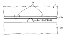
ここで、ロータ1における突起部2c−1〜2c−3と接する面の一例について説明する。ロータ1においては、ロータ1の移動方向に沿って、異なる形態を周期的に形成しておけばよい。それにより、超音波アクチュエータ100において、高精度の位置決め制御を実現できる。例えば、ロータ1における突起部2c−1、2c−2、2c−3と接する面には、ロータ1の円周に沿って周期的にその形状あるいは性質を変化させてある。具体的には、中心から径方向に沿って伸びる複数の溝(凹部)が円周に沿って等間隔に形成されている。ここで、図8〜図10を用いて、ロータ1における突起部2c−1、2c−2、2c−3と接する面について説明する。図8は本実施形態に係るロータと接触部との分解斜視図である。図9は本実施形態に係るロータにおける接触部と接する面の形状を説明する図である。図10は薄板を備えたロータおよび接触部の要部拡大側面図である。   Here, an example of the surface in contact with the protrusions 2c-1 to 2c-3 in the rotor 1 will be described. In the rotor 1, different forms may be periodically formed along the moving direction of the rotor 1. Thereby, highly accurate positioning control can be realized in the ultrasonic actuator 100. For example, the shape or property of the surface of the rotor 1 that contacts the protrusions 2c-1, 2c-2, and 2c-3 is periodically changed along the circumference of the rotor 1. Specifically, a plurality of grooves (concave portions) extending along the radial direction from the center are formed at equal intervals along the circumference. Here, the surface in contact with the protrusions 2c-1, 2c-2, and 2c-3 in the rotor 1 will be described with reference to FIGS. FIG. 8 is an exploded perspective view of the rotor and the contact portion according to the present embodiment. FIG. 9 is a view for explaining the shape of the surface in contact with the contact portion in the rotor according to the present embodiment. FIG. 10 is an enlarged side view of a main part of a rotor and a contact portion provided with a thin plate.

図8に示すように、振動体2(図示せず)の接触部2aは、ロータ1側の面に複数の突起部2c−1〜2c−3を備えている。ロータ1と接触部2aとの間には所定の付勢力がかかり、これらは密着している。この場合に、接触部2aは、突起部2c−1〜2c−3においてロータ1と接触している。したがって、ロータ1から力が加わるのは突起部2c−1〜2c−3のみであり、接触部2a全体に力が加わるわけではない。   As shown in FIG. 8, the contact portion 2a of the vibrating body 2 (not shown) includes a plurality of protrusions 2c-1 to 2c-3 on the surface on the rotor 1 side. A predetermined urging force is applied between the rotor 1 and the contact portion 2a, and these are in close contact with each other. In this case, the contact part 2a is in contact with the rotor 1 at the protrusions 2c-1 to 2c-3. Therefore, the force is applied only from the rotor 1 to the protrusions 2c-1 to 2c-3, and the force is not applied to the entire contact portion 2a.

図9に示すように、ロータ1における接触部2aと接触している面には、ロータ1の中心を通り、径方向に沿って伸びる溝1aが形成されている。なお、溝1aは3つであって、円周に沿って等間隔に形成されている。したがって、隣接する溝1aはロータ1の中心に対して互いに120度回転させた配置である。このような構成であることから、溝(第2の領域)1aが形成されている箇所と形成されていない箇所(第1の領域)とが交互に、ロータ1の円周上に沿って配置されている。このような構成であることから、圧電振動子2b(図示せず)が振動することによりロータ1に接触している突起部2c−1〜2c−3が楕円振動し、それによりロータ1が駆動した場合に、突起部2c−1〜2c−3は周期的に溝1aを通過することとなる。突起部2c−1〜2c−3が溝1aの形成箇所に位置する場合と、溝1aが形成されていない箇所に位置する場合とでは、接触部2aに加わる力が異なる。それにより、ロータ1が回転することで圧電振動子2bの振動状態が変化する。   As shown in FIG. 9, a groove 1 a that passes through the center of the rotor 1 and extends along the radial direction is formed on the surface of the rotor 1 that is in contact with the contact portion 2 a. The number of the grooves 1a is three, and they are formed at equal intervals along the circumference. Therefore, the adjacent grooves 1 a are arranged so as to be rotated 120 degrees with respect to the center of the rotor 1. Because of such a configuration, the locations where the grooves (second regions) 1a are formed and the locations where the grooves (second regions) 1a are not formed (first regions) are alternately arranged along the circumference of the rotor 1. Has been. Due to such a configuration, when the piezoelectric vibrator 2b (not shown) vibrates, the protrusions 2c-1 to 2c-3 in contact with the rotor 1 elliptically vibrate, thereby driving the rotor 1. In this case, the protrusions 2c-1 to 2c-3 periodically pass through the groove 1a. The force applied to the contact portion 2a is different between the case where the protrusions 2c-1 to 2c-3 are located at the location where the groove 1a is formed and the case where the projection 2c-1 to 2c-3 is located where the groove 1a is not formed. Thereby, the vibration state of the piezoelectric vibrator 2b changes as the rotor 1 rotates.

また、図10に示すように、ロータ1には、接触部2a側の面を覆うように薄板1bが設置されていてもよい。このような構成とすることで、突起部2c−1(2c−2、2c−3)が溝1a上を通過する際のガタツキを防止することができる。例えば、ロータ1は、ステンレスなどの金属からなる構成とすればよい。そして、溝1aはロータ1に機械加工やエッチングなどにより形成すればよい。また、薄板1bはステンレスなどとすればよい。なお、薄板1bには、耐摩耗性を向上させるため、窒化処理などを施しておくことが好ましい。ロータ1と薄板1bとは、それらの間に薄い接着層を形成するなどして接合、または、中心付近をスポット溶接などで結合すればよい。この場合は、突起部2c−1と薄板1bとが接触し、突起部2c−1の楕円振動により薄板1bがつき動かされるので、薄板1bからロータ1に回転駆動が確実に伝達される構成であればよい。また、このような構成において、溝1aが形成されている箇所には、空洞が形成されていることになる。したがって、溝1aの形成箇所(第2の領域)と、溝1aが形成されていない箇所(第1の領域)とでは、薄板1bのばね定数が異なる。つまり、薄板1bにおいて溝1aの形成箇所は、溝1aが形成されていない箇所に比べて剛性が低い。したがって、薄板1bにおいて、溝1aの形成箇所に突起部2c−1が位置するか否かにより、圧電振動子2bの振動状態が変化する。このように、ロータ1に対する突起部2c−1の位置に応じて圧電振動子2bの振動状態が変化する。   Moreover, as shown in FIG. 10, the rotor 1 may be provided with a thin plate 1b so as to cover the surface on the contact portion 2a side. By setting it as such a structure, the rattling at the time of protrusion 2c-1 (2c-2, 2c-3) passing on the groove | channel 1a can be prevented. For example, the rotor 1 may be made of a metal such as stainless steel. The groove 1a may be formed in the rotor 1 by machining or etching. The thin plate 1b may be stainless steel or the like. The thin plate 1b is preferably subjected to nitriding treatment or the like in order to improve wear resistance. The rotor 1 and the thin plate 1b may be joined by forming a thin adhesive layer between them, or the vicinity of the center may be joined by spot welding or the like. In this case, the protrusion 2c-1 and the thin plate 1b are in contact with each other, and the thin plate 1b is moved by the elliptical vibration of the protrusion 2c-1, so that the rotational drive is reliably transmitted from the thin plate 1b to the rotor 1. I just need it. Further, in such a configuration, a cavity is formed at a location where the groove 1a is formed. Accordingly, the spring constant of the thin plate 1b is different between the location where the groove 1a is formed (second region) and the location where the groove 1a is not formed (first region). That is, in the thin plate 1b, the location where the groove 1a is formed is less rigid than the location where the groove 1a is not formed. Therefore, in the thin plate 1b, the vibration state of the piezoelectric vibrator 2b changes depending on whether or not the protrusion 2c-1 is located at the position where the groove 1a is formed. Thus, the vibration state of the piezoelectric vibrator 2b changes according to the position of the protrusion 2c-1 with respect to the rotor 1.

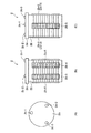
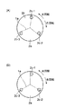
なお、本実施形態においては、上述のように、各突起部2c−1〜2c−3の配置が等間隔ではない。そして、ロータ1が移動した場合における、突起部2c−1〜2c−3と溝1aとの位置関係としては、以下に示す位置関係のみが存在するように、突起部2c−1〜2c−3および溝1aが配置される構成とする。図11は本実施形態に係る超音波アクチュエータにおける突起部と溝との位置関係を示す図であって、図11(A)は第1検出状態における突起部と溝との位置関係を示す図であり、図11(B)は第2検出状態における突起部と溝との位置関係を示す図である。図11(A)および(B)は接触部2aの平面図であり、接触部2a上に突起部2c−1〜2c−3が設置されていて、溝1aの位置が仮想的に示されている。なお、図11(A)の状態からロータ1(図示せず)が右回転(時計回りに回転)した状態が図11(B)に示す状態である。上述のように、突起部2c−2および2c−3は接触部2aの中心に対して120度離れているが、突起部2c−1は、突起部2c−2および2c−3のそれぞれに対して115度、125度離れている。なお、突起部2c−1〜2c−3が接するロータ1において、溝1a以外の箇所は、以下では、駆動域(第1の領域)という。   In the present embodiment, as described above, the arrangement of the protrusions 2c-1 to 2c-3 is not equal. Then, as the positional relationship between the protrusions 2c-1 to 2c-3 and the groove 1a when the rotor 1 moves, the protrusions 2c-1 to 2c-3 are present so that only the following positional relationship exists. And the groove 1a is arranged. FIG. 11 is a diagram illustrating the positional relationship between the protrusion and the groove in the ultrasonic actuator according to the present embodiment, and FIG. 11A is a diagram illustrating the positional relationship between the protrusion and the groove in the first detection state. FIG. 11B is a diagram showing the positional relationship between the protrusion and the groove in the second detection state. FIGS. 11A and 11B are plan views of the contact portion 2a, in which protrusions 2c-1 to 2c-3 are installed on the contact portion 2a, and the position of the groove 1a is virtually shown. Yes. In addition, the state which the rotor 1 (not shown) rotated right (rotated clockwise) from the state of FIG. 11 (A) is a state shown to FIG. 11 (B). As described above, the protrusions 2c-2 and 2c-3 are 120 degrees away from the center of the contact part 2a, but the protrusion 2c-1 is different from the protrusions 2c-2 and 2c-3, respectively. 115 degrees and 125 degrees apart. In the rotor 1 with which the protrusions 2c-1 to 2c-3 are in contact with each other, a portion other than the groove 1a is hereinafter referred to as a drive region (first region).

まず、突起部2c−1〜2c−3のすべてが、駆動域に位置する状態(以下、駆動状態)と、突起部2c−1〜2c−3の一部が駆動域に位置し、突起部2c−1〜2c−3の残りの突起部2c−1〜2c−3が溝1aに位置する状態(以下、検出状態)とがある。さらに、この検出状態においても、溝1aまたは駆動域に位置する突起部2c−1〜2c−3の数によって第1検出状態および第2検出状態の2つの種類がある。本実施形態においては、図11(A)に示すように、3つの突起部2c−1〜2c−3のうち、溝1aに位置するいずれかの突起部2c−1〜2c−3の数が1つの場合を第1検出状態とする。そして、図11(B)に示すように、溝1aに位置するいずれかの突起部2c−1〜2c−3の数が2つの場合を第2検出状態とする。また、言い換えると、3つの突起部2c−1〜2c−3のうち、駆動域に位置するいずれかの突起部2c−1〜2c−3の数が2つの場合を第1検出状態とし、駆動域に位置するいずれかの突起部2c−1〜2c−3の数が1つの場合を第2検出状態とし、突起部2c−1〜2c−3のすべてが駆動域に位置する場合を駆動状態とする。   First, a state in which all of the protrusions 2c-1 to 2c-3 are located in the drive area (hereinafter referred to as drive state), and a part of the protrusions 2c-1 to 2c-3 are located in the drive area. There is a state where the remaining protrusions 2c-1 to 2c-3 of 2c-1 to 2c-3 are positioned in the groove 1a (hereinafter referred to as a detection state). Further, even in this detection state, there are two types of first detection state and second detection state depending on the number of protrusions 2c-1 to 2c-3 located in the groove 1a or the drive region. In the present embodiment, as shown in FIG. 11 (A), the number of any of the protrusions 2c-1 to 2c-3 located in the groove 1a out of the three protrusions 2c-1 to 2c-3 is One case is defined as a first detection state. And as shown in FIG.11 (B), let the case where the number of any one of the projection parts 2c-1 to 2c-3 located in the groove | channel 1a is two be a 2nd detection state. Further, in other words, among the three protrusions 2c-1 to 2c-3, the case where any one of the protrusions 2c-1 to 2c-3 located in the drive region is two is set as the first detection state, and the drive The case where one of the protrusions 2c-1 to 2c-3 located in the area is one is set as the second detection state, and the case where all of the protrusions 2c-1 to 2c-3 are located in the drive area is the drive state. And

より具体的には、本実施形態に係る超音波アクチュエータにおいては、第1検出状態では、互いに120度離れた突起部2c−2および2c−3が共に駆動域に位置し、残りの突起部2c−1は溝1aに位置している。また、第2検出状態では、互いに120度離れた突起部2c−2および2c−3が共に溝1aに位置し、残りの突起部2c−1は駆動域に位置している。そして、駆動状態では、すべての突起部2c−1〜2c−3が駆動域に位置している。これら駆動状態、第1検出状態および第2検出状態においては、それぞれ、圧電振動子2bに加わる力も異なることから、圧電振動子2bの振動状態も異なる。   More specifically, in the ultrasonic actuator according to the present embodiment, in the first detection state, the protrusions 2c-2 and 2c-3 that are 120 degrees apart from each other are both positioned in the drive range, and the remaining protrusions 2c. -1 is located in the groove 1a. In the second detection state, the protrusions 2c-2 and 2c-3 that are 120 degrees apart from each other are located in the groove 1a, and the remaining protrusions 2c-1 are located in the drive range. In the driving state, all the protrusions 2c-1 to 2c-3 are located in the driving range. In the drive state, the first detection state, and the second detection state, since the force applied to the piezoelectric vibrator 2b is also different, the vibration state of the piezoelectric vibrator 2b is also different.

ここで、圧電振動子2bの振動状態の具体的な検出方法について説明する。具体的には、検知信号取出し電極2b−5から出力される信号により振動状態の変化を検出することができる。すなわち、ロータ1が回転することで、検知信号取出し電極2b−5に接続される振動状態検知電極14の形成箇所の圧電薄板20に加わる力は周期的に変化する。それにより、振動状態検知電極14から出力される振動検知電圧と駆動電圧との位相差が変化する。したがって、振動検知電圧と駆動電圧との位相差から、圧電振動子2bの振動状態を検出できる。   Here, a specific method for detecting the vibration state of the piezoelectric vibrator 2b will be described. Specifically, the change in the vibration state can be detected by a signal output from the detection signal extraction electrode 2b-5. That is, as the rotor 1 rotates, the force applied to the piezoelectric thin plate 20 at the location where the vibration state detection electrode 14 connected to the detection signal extraction electrode 2b-5 is changed periodically. As a result, the phase difference between the vibration detection voltage output from the vibration state detection electrode 14 and the drive voltage changes. Therefore, the vibration state of the piezoelectric vibrator 2b can be detected from the phase difference between the vibration detection voltage and the drive voltage.

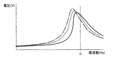
図12は、振動検知電圧と駆動電圧の周波数との関係を示すグラフであり、図13は、駆動電圧に対する振動検知電圧の位相と、駆動電圧の周波数との関係を示すグラフである。図12において、縦軸は振動検知電圧の値を示し、横軸は駆動電圧の周波数を示す。図12は、図10に示すようにロータ1に溝1aが形成され、薄板1bが形成された場合に、駆動状態、第1検出状態および第2検出状態における、超音波アクチュエータ100の振動検知電圧と周波数との関係を表している。図12において、実線は駆動状態を示し、破線は第1検出状態を示し、一点鎖線は第2検出状態を示す。図12に示すように、駆動状態に比べて第1検出状態における共振周波数の方が低い。また、第1検出状態に比べて第2検出状態における共振周波数が低い。このように、駆動状態、第1検出状態および第2検出状態においては、それぞれ圧電振動子2bの振動状態が変化していることが分かる。また、駆動状態、第1検出状態および第2検出状態における共振周波数よりやや大きな周波数fにて超音波アクチュエータ100を駆動させている場合に、駆動状態、第1検出状態および第2検出状態における振動検知電圧は、それぞれ異なる値である。具体的には、駆動状態、第1検出状態、第2検出状態の順で振動検知電圧の値は低くなっている。 FIG. 12 is a graph showing the relationship between the vibration detection voltage and the frequency of the drive voltage, and FIG. 13 is a graph showing the relationship between the phase of the vibration detection voltage with respect to the drive voltage and the frequency of the drive voltage. In FIG. 12, the vertical axis indicates the value of the vibration detection voltage, and the horizontal axis indicates the frequency of the drive voltage. FIG. 12 shows the vibration detection voltage of the ultrasonic actuator 100 in the drive state, the first detection state, and the second detection state when the groove 1a is formed in the rotor 1 and the thin plate 1b is formed as shown in FIG. And the relationship between frequencies. In FIG. 12, the solid line indicates the driving state, the broken line indicates the first detection state, and the alternate long and short dash line indicates the second detection state. As shown in FIG. 12, the resonance frequency in the first detection state is lower than that in the driving state. Further, the resonance frequency in the second detection state is lower than that in the first detection state. Thus, it can be seen that the vibration state of the piezoelectric vibrator 2b changes in the drive state, the first detection state, and the second detection state. Further, when the ultrasonic actuator 100 is driven at a frequency f 1 slightly higher than the resonance frequency in the driving state, the first detection state, and the second detection state, in the driving state, the first detection state, and the second detection state. The vibration detection voltages have different values. Specifically, the value of the vibration detection voltage is lower in the order of the driving state, the first detection state, and the second detection state.

また、図13は、図10に示すようにロータ1に溝1aが形成され、薄板1bが形成された場合に、駆動状態、第1検出状態および第2検出状態における、超音波アクチュエータ100の駆動電圧に対する振動検知電圧の位相と、駆動電圧の周波数との関係を表している。図13において、実線は駆動状態を示し、破線は第1検出状態を示し、一点鎖線は第2検出状態を示す。図13に示すように、駆動状態、第1検出状態および第2検出状態において、駆動電圧の周波数が共振周波数付近の周波数fである場合には、それぞれ前記位相が異なる。具体的には、駆動電圧が周波数fである場合は、第1検出状態および第2検出状態における、駆動状態を基準とした位相差はそれぞれΔおよびΔである。また、図14は駆動状態、第1検出状態および第2検出状態における、駆動電圧と振動検知電圧との波形について示したグラフである。図14において、各グラフにおいて、縦軸は電圧であり、横軸は時間である。また、各グラフにおいて、実線は駆動電圧であり、破線は振動検知電圧である。図14に示すように、駆動状態に比べて第1検出状態では、振動検知電圧の位相がずれ、第1検出状態に比べて第2検出状態ではさらに、振動検知電圧の位相がずれている。 FIG. 13 shows the driving of the ultrasonic actuator 100 in the driving state, the first detection state, and the second detection state when the groove 1a is formed in the rotor 1 and the thin plate 1b is formed as shown in FIG. The relationship between the phase of the vibration detection voltage with respect to the voltage and the frequency of the drive voltage is shown. In FIG. 13, the solid line indicates the driving state, the broken line indicates the first detection state, and the alternate long and short dash line indicates the second detection state. As shown in FIG. 13, in the driving state, the first detection state, and the second detection state, when the frequency of the driving voltage is the frequency f 1 near the resonance frequency, the phases are different from each other. Specifically, when the driving voltage is frequency f 1 , the phase differences based on the driving state in the first detection state and the second detection state are Δ 1 and Δ 2 , respectively. FIG. 14 is a graph showing waveforms of the drive voltage and the vibration detection voltage in the drive state, the first detection state, and the second detection state. In FIG. 14, in each graph, the vertical axis represents voltage, and the horizontal axis represents time. In each graph, the solid line is the drive voltage, and the broken line is the vibration detection voltage. As shown in FIG. 14, the phase of the vibration detection voltage is shifted in the first detection state as compared to the driving state, and the phase of the vibration detection voltage is further shifted in the second detection state as compared to the first detection state.

このように、駆動状態、第1検出状態および第2検出状態に応じて、駆動状態を基準とした位相差が変化することから、この位相差から超音波アクチュエータ100において駆動状態、第1検出状態および第2検出状態のいずれであるかを検出することができる。駆動状態、第1検出状態および第2検出状態は周期的に生じることから、これらを検出することで、ロータ1の回転位置や回転方向等を含むロータ1の位置情報を検出することができる。   Thus, since the phase difference based on the driving state changes according to the driving state, the first detection state, and the second detection state, the driving state, the first detection state in the ultrasonic actuator 100 from this phase difference. And the second detection state can be detected. Since the drive state, the first detection state, and the second detection state occur periodically, the position information of the rotor 1 including the rotation position and the rotation direction of the rotor 1 can be detected by detecting these.

次に、本実施形態に係る超音波アクチュエータ100の動作について説明する。まず、制御部11がロータ1を駆動する指令のための電気信号である駆動信号を出力する。駆動電圧生成部12は、制御部11からの駆動信号に応じた駆動電圧を生成する。このとき、生成された駆動電圧は、駆動電圧変換部16にて検出され、パルス信号へと変換される。また、駆動電圧の周波数は共振周波数付近の値であるfとすればよい。また、駆動電圧は駆動電流生成部13に入力され、駆動電流生成部13は駆動電圧に対応する駆動電流を生成する。なお、駆動電圧および駆動電流は交流である。駆動電流は、圧電振動子2bに入力され、圧電振動子2bが振動することで、各突起部2c−1〜2c−3は楕円振動を行い、それによって、ロータ1が回転する。なお、このときに発生する振動検知電圧は、振動状態検知電極14により検出され、検知電圧変換部15に出力される。検知電圧変換部15は振動検知電圧をパルス信号に変換する。演算部17は、パルス信号とされた駆動電圧および振動検知電圧より、駆動電圧に対する振動検知電圧の位相を求め、さらに、駆動状態を基準とした位相差を求める。パルス信号に変換することで、位相差を信号情報(レベル)として検出することができるため好ましい。それにより、容易に位相差を検出することができる。 Next, the operation of the ultrasonic actuator 100 according to this embodiment will be described. First, the control unit 11 outputs a drive signal that is an electric signal for a command to drive the rotor 1. The drive voltage generation unit 12 generates a drive voltage according to the drive signal from the control unit 11. At this time, the generated drive voltage is detected by the drive voltage converter 16 and converted into a pulse signal. Further, the frequency of the drive voltage may be set to f 1 that is a value near the resonance frequency. Further, the drive voltage is input to the drive current generation unit 13, and the drive current generation unit 13 generates a drive current corresponding to the drive voltage. The drive voltage and drive current are alternating current. The drive current is input to the piezoelectric vibrator 2b, and when the piezoelectric vibrator 2b vibrates, each of the protrusions 2c-1 to 2c-3 performs an elliptical vibration, whereby the rotor 1 rotates. The vibration detection voltage generated at this time is detected by the vibration state detection electrode 14 and output to the detection voltage conversion unit 15. The detection voltage converter 15 converts the vibration detection voltage into a pulse signal. The computing unit 17 obtains the phase of the vibration detection voltage with respect to the drive voltage from the drive voltage and the vibration detection voltage that are converted into pulse signals, and further obtains a phase difference based on the drive state. Conversion to a pulse signal is preferable because the phase difference can be detected as signal information (level). Thereby, the phase difference can be easily detected.

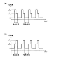
具体的には、演算部17により求められた位相差は、図15に示すグラフで表される。図15は、本実施形態に係る超音波アクチュエータが駆動している場合の、駆動状態を基準とした位相差の時間変化を示すグラフであって、図15(A)はロータが右回転している場合における位相差の時間変化を示すグラフであり、図15(B)はロータが左回転している場合における位相差の時間変化を示すグラフである。ロータ1が右回転している場合は、図11において、仮想的に示した溝1aが右回転(時計回り)している場合である。図11(B)に示す第2検出状態の場合に最も位相差(Δ)が大きくなる。そして、その状態から、溝1aが右回転すると、すぐに図11(B)に示す第1検出状態となる。このとき、位相差はΔよりも小さく、駆動状態における位相差よりも大きな位相差(Δ)となる。そして、さらに溝1aが右回転を続けると、駆動状態となる。そして、駆動状態がしばらく続き、その後第2検出状態となり、図15(A)に示すように、第2検出状態、第1検出状態、駆動状態を繰り返す。このように、本実施形態に係る超音波アクチュエータ100においては、右回転の場合は第2検出状態から連続して第1検出状態となり、さらに連続して駆動状態となるサイクルを繰り返す。 Specifically, the phase difference obtained by the calculation unit 17 is represented by a graph shown in FIG. FIG. 15 is a graph showing a temporal change in the phase difference based on the driving state when the ultrasonic actuator according to the present embodiment is driven. FIG. FIG. 15B is a graph showing the time change of the phase difference when the rotor is rotating counterclockwise. The case where the rotor 1 is rotating clockwise is a case where the groove 1a shown in FIG. 11 is rotating clockwise (clockwise). In the second detection state shown in FIG. 11B, the phase difference (Δ 2 ) becomes the largest. From this state, when the groove 1a rotates to the right, the first detection state shown in FIG. At this time, the phase difference is smaller than Δ 2 and larger than the phase difference in the driving state (Δ 1 ). And if the groove | channel 1a continues right rotation, it will be in a drive state. Then, the drive state continues for a while, and then enters the second detection state, and the second detection state, the first detection state, and the drive state are repeated as shown in FIG. As described above, in the ultrasonic actuator 100 according to the present embodiment, in the case of the right rotation, the cycle from the second detection state to the first detection state continuously and further to the drive state is repeated.

また、ロータ1が左回転している場合は、図11において、仮想的に示した溝1aが左回転(反時計回り)している場合である。図11(A)に示すように第1検出状態の場合に位相差がΔとなる。そして、その状態から、溝1aが左回転すると、すぐに図11(A)に示す第2検出状態となる。このとき、位相差は最も大きい位相差であるΔとなる。そして、さらに溝1aが左回転を続けると、駆動状態となる。そして、駆動状態がしばらく続き、その後第1検出状態となり、図15(B)に示すように、第1検出状態、第2検出状態、駆動状態を繰り返す。このように、本実施形態に係る超音波アクチュエータ100においては、左回転の場合は第1検出状態から連続して第2検出状態となり、さらに連続して駆動状態となるサイクルを繰り返す。このように、右回転と左回転とでは、時間変化における位相差を示したグラフの波形が異なる。 Further, the case where the rotor 1 rotates counterclockwise is the case where the groove 1a virtually illustrated in FIG. 11 rotates counterclockwise (counterclockwise). Phase difference in the case of the first detection state, as shown in FIG. 11 (A) is delta 1. From this state, when the groove 1a rotates counterclockwise, the second detection state shown in FIG. At this time, the phase difference is Δ 2 which is the largest phase difference. And if the groove | channel 1a continues left rotation, it will be in a drive state. Then, the driving state continues for a while, and then enters the first detection state, and the first detection state, the second detection state, and the driving state are repeated as shown in FIG. As described above, in the ultrasonic actuator 100 according to the present embodiment, in the case of the left rotation, the cycle in which the detection state is continuously changed from the first detection state to the second detection state and further is continuously driven is repeated. Thus, the waveform of the graph showing the phase difference in the time change differs between right rotation and left rotation.

制御部11の制御により、さらに演算部17は上記求めた時間変化に対する位相差をもとに、ロータ1の位置、回転数、回転方向、移動量等のロータ1の位置情報を算出する。具体的には、ロータ1が回転することで、第1検出状態および第2検出状態を含む検出状態と、駆動状態が周期的に繰り返されることになる。溝1aの配置は規則性があることから、検出状態および駆動状態となった数をカウントしておくことで、ロータ1の回転数や回転量を算出することができる。また、上述のように、右回転と左回転とでは、位相差の波形が異なることから、これら波形により容易に回転方向を算出することができる。   Under the control of the control unit 11, the calculation unit 17 further calculates the position information of the rotor 1 such as the position, rotation speed, rotation direction, and movement amount of the rotor 1 based on the phase difference with respect to the obtained time change. Specifically, when the rotor 1 rotates, the detection state including the first detection state and the second detection state and the drive state are periodically repeated. Since the arrangement of the grooves 1a is regular, the number of rotations and the amount of rotation of the rotor 1 can be calculated by counting the number of detected and driven states. Further, as described above, since the waveform of the phase difference is different between the right rotation and the left rotation, the rotation direction can be easily calculated from these waveforms.

また、本実施形態に係る超音波アクチュエータ100において、接触部2aは、ロータ1に突起部2c−1〜2c−3の頂点で接していることから、溝1aと駆動域との境界付近においても、それらの領域の違いを正確に高精度に検出することができる。また、圧電振動子2bの振動状態、すなわち駆動状態、第1検出状態および第2検出状態の別を、デジタル的に検出することができるため、位相差の検出等も容易に行うことができる。   Further, in the ultrasonic actuator 100 according to the present embodiment, the contact portion 2a is in contact with the rotor 1 at the apex of the protrusions 2c-1 to 2c-3, so that the contact portion 2a is also near the boundary between the groove 1a and the drive region. The difference between these areas can be detected accurately and with high accuracy. Further, since the vibration state of the piezoelectric vibrator 2b, that is, the driving state, the first detection state, and the second detection state can be detected digitally, phase difference detection and the like can be easily performed.

このようにして、演算部17で算出されたロータ1の位置情報は制御部11へと送られる。演算部17において算出されたロータ1の位置情報に基づいて、現在のロータの回転状態を認識できるため、制御部11はこの位置情報に基づいてロータ1の回転駆動を制御することで、所望の回転制御を正確に行うことができる。具体的には、操作者が所望とする回転数だけロータ1を回転させ、その際の回転方向も操作者の所望とする回転方向とすることできる。それにより、本実施形態に係る超音波アクチュエータ100は、ロータリーエンコーダ等を取り付けることなく、高精度の位置制御等が可能である。   In this way, the position information of the rotor 1 calculated by the calculation unit 17 is sent to the control unit 11. Since the current rotation state of the rotor can be recognized based on the position information of the rotor 1 calculated by the calculation unit 17, the control unit 11 controls the rotation drive of the rotor 1 based on this position information. The rotation control can be performed accurately. Specifically, the rotor 1 can be rotated by the number of rotations desired by the operator, and the rotation direction at that time can also be the rotation direction desired by the operator. Thereby, the ultrasonic actuator 100 according to the present embodiment can perform highly accurate position control without attaching a rotary encoder or the like.

また、上記本実施形態に係る超音波アクチュエータ100は、溝1aを規則的に配置し、突起部2c−1〜2c−3の配置を不規則な箇所を含むように構成したが、溝1aの配置を不規則な箇所を含むようにし、突起部2c−1〜2c−3を規則的に配置することとしてもよい。このような本発明の他の実施形態に係る超音波アクチュエータについて図を用いて説明する。図16は本発明における他の実施形態に係る超音波アクチュエータの突起部と溝との位置関係を示す図であって、図16(A)は第1検出状態における突起部と溝との位置関係を示す図であり、図16(B)は第2検出状態における突起部と溝との位置関係を示す図である。なお、図16(A)および(B)における本発明の他の実施形態に係る超音波アクチュエータは、上述した本実施形態に係る超音波アクチュエータ100とは、溝1a(1a−1〜1a−3)および突起部2c−1〜2c−3の配置が異なるだけで他の点は略同一であるので、同一の構成については同一の符号を付し、同一の点については説明を省略する。   In addition, the ultrasonic actuator 100 according to the present embodiment is configured such that the grooves 1a are regularly arranged and the protrusions 2c-1 to 2c-3 are arranged to include irregular portions. It is good also as arrangement | positioning including an irregular location and arrange | positioning the protrusion parts 2c-1 to 2c-3 regularly. Such an ultrasonic actuator according to another embodiment of the present invention will be described with reference to the drawings. FIG. 16 is a diagram showing the positional relationship between the protrusions and grooves of an ultrasonic actuator according to another embodiment of the present invention, and FIG. 16 (A) is the positional relationship between the protrusions and grooves in the first detection state. FIG. 16B is a diagram showing the positional relationship between the protrusion and the groove in the second detection state. 16A and 16B, the ultrasonic actuator according to another embodiment of the present invention is different from the ultrasonic actuator 100 according to this embodiment described above in the grooves 1a (1a-1 to 1a-3). ) And the protrusions 2c-1 to 2c-3 are different in other respects, and the other points are substantially the same. Therefore, the same components are denoted by the same reference numerals, and the description of the same points is omitted.

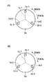
図16(A)および(B)は接触部2aの平面図であり、接触部2a上に突起部2c−1〜2c−3が設置されていて、図示していないロータ1に形成された溝1a−1〜1a−3の位置が仮想的に示されている。なお、図16(B)の状態からロータが時計回りに回転した状態が図16(A)に示す状態である。突起部2c−1〜2c−3はそれぞれ接触部2aの中心に対して同心円上にあり、それぞれ120度離れて設置されている。また、3つの溝1a−1〜1a−3がロータ1において、ロータ1(図示せず)における接触部2aと接触している面の中心を通り、径方向に沿って伸びるように形成されている。なお、上述のように、溝1a−1〜1a−3は円周に沿って不規則な配置とされる。具体的には、溝1a−2および1a−3は、互いにロータ1の中心に対して120度回転させた配置であり、溝1a−3と溝1a−1とは互いにロータ1の中心に対して115度回転させた配置であり、溝1a−1と溝1a−2とは互いにロータ1の中心に対して125度回転させた配置である。なお、突起部2c−1〜2c−3が接するロータ1において、溝1a−1〜1a−3以外の箇所は、以下では、駆動域という。   FIGS. 16A and 16B are plan views of the contact portion 2a. The protrusions 2c-1 to 2c-3 are installed on the contact portion 2a, and grooves formed in the rotor 1 (not shown). The positions 1a-1 to 1a-3 are virtually shown. In addition, the state which the rotor rotated clockwise from the state of FIG. 16 (B) is a state shown to FIG. 16 (A). The protrusions 2c-1 to 2c-3 are concentric with respect to the center of the contact part 2a, and are disposed 120 degrees apart from each other. Three grooves 1a-1 to 1a-3 are formed in the rotor 1 so as to extend along the radial direction through the center of the surface of the rotor 1 (not shown) in contact with the contact portion 2a. Yes. As described above, the grooves 1a-1 to 1a-3 are irregularly arranged along the circumference. Specifically, the grooves 1 a-2 and 1 a-3 are arranged to be rotated 120 degrees with respect to the center of the rotor 1, and the grooves 1 a-3 and the groove 1 a-1 are mutually with respect to the center of the rotor 1. The groove 1 a-1 and the groove 1 a-2 are each rotated by 125 degrees with respect to the center of the rotor 1. In the rotor 1 with which the protrusions 2c-1 to 2c-3 are in contact, the portions other than the grooves 1a-1 to 1a-3 are hereinafter referred to as drive areas.

そして、ロータ1が回転することで、突起部2c−1〜2c−3と溝1a−1〜1a−3との位置関係により、突起部2c−1〜2c−3のすべてが、駆動域に位置する駆動状態と、突起部2c−1〜2c−3の一部が駆動域に位置し、突起部2c−1〜2c−3の残りの突起部2c−1〜2c−3が溝1a−1〜1a−3に位置する検出状態とがある。さらに、この検出状態においても、溝1a−1〜1a−3または駆動域に位置する突起部2c−1〜2c−3の数によって第1検出状態および第2検出状態の2つの種類がある。他の実施形態においては、図16(A)に示すように、3つの突起部2c−1〜2c−3のうち、溝1a−1〜1a−3に位置するいずれかの突起部2c−1〜2c−3の数が1つの場合を第1検出状態とする。そして、図16(B)に示すように、溝1a−1〜1a−3に位置するいずれかの突起部2c−1〜2c−3の数が2つの場合を第2検出状態とする。また、言い換えると、3つの突起部2c−1〜2c−3のうち、駆動域に位置するいずれかの突起部2c−1〜2c−3の数が2つの場合を第1検出状態とし、駆動域に位置するいずれかの突起部2c−1〜2c−3の数が1つの場合を第2検出状態とし、突起部2c−1〜2c−3のすべてが駆動域に位置する場合を駆動状態とする。   When the rotor 1 rotates, all of the protrusions 2c-1 to 2c-3 are brought into the drive range due to the positional relationship between the protrusions 2c-1 to 2c-3 and the grooves 1a-1 to 1a-3. The driving state that is positioned, a part of the protrusions 2c-1 to 2c-3 are located in the drive region, and the remaining protrusions 2c-1 to 2c-3 of the protrusions 2c-1 to 2c-3 are grooves 1a- There are detection states located at 1-1a-3. Further, even in this detection state, there are two types of detection states, a first detection state and a second detection state, depending on the number of grooves 1a-1 to 1a-3 or the protrusions 2c-1 to 2c-3 located in the drive range. In another embodiment, as shown in FIG. 16A, of the three protrusions 2c-1 to 2c-3, any one of the protrusions 2c-1 located in the grooves 1a-1 to 1a-3 The case where the number of ~ 2c-3 is one is set as the first detection state. And as shown in FIG.16 (B), let the case where the number of any protrusion part 2c-1 to 2c-3 located in the groove | channels 1a-1 to 1a-3 is two be a 2nd detection state. Further, in other words, among the three protrusions 2c-1 to 2c-3, the case where any one of the protrusions 2c-1 to 2c-3 located in the drive region is two is set as the first detection state, and the drive The case where one of the protrusions 2c-1 to 2c-3 located in the area is one is set as the second detection state, and the case where all of the protrusions 2c-1 to 2c-3 are located in the drive area is the drive state. And

より具体的には、他の実施形態に係る超音波アクチュエータにおいては、第1検出状態(図16(A)参照)では、突起部2c−1が溝1a−1に位置し、突起部2c−2および2c−3は駆動域に位置している。そして、第2検出状態(図16(B)参照)では、突起部2c−2および2c−3が溝1a−2および1a−3に位置し、突起部2c−1は駆動域に位置している。そして、駆動状態では、すべての突起部2c−1〜2c−3が駆動域に位置している。これら駆動状態、第1検出状態および第2検出状態においては、それぞれ、圧電振動子2bに加わる力も異なることから、圧電振動子2bの振動状態も異なる。   More specifically, in the ultrasonic actuator according to another embodiment, in the first detection state (see FIG. 16A), the protrusion 2c-1 is positioned in the groove 1a-1, and the protrusion 2c- 2 and 2c-3 are located in the drive range. In the second detection state (see FIG. 16B), the protrusions 2c-2 and 2c-3 are located in the grooves 1a-2 and 1a-3, and the protrusion 2c-1 is located in the drive range. Yes. In the driving state, all the protrusions 2c-1 to 2c-3 are located in the driving range. In the drive state, the first detection state, and the second detection state, since the force applied to the piezoelectric vibrator 2b is also different, the vibration state of the piezoelectric vibrator 2b is also different.

そして、このような、他の実施形態に係る超音波アクチュエータにおいて、まず、図16(B)に示す第2検出状態の場合に最も位相差(Δ)が大きくなり、その状態から溝1a−1〜1a−3が右回転すると、すぐに図16(A)に示す第1検出状態となる。このとき、位相差はΔよりも小さく、駆動状態における位相差よりも大きなΔとなる。そして、さらに溝1a−1〜1a−3が右回転を続けると、駆動状態となる。そして、駆動状態がしばらく続き、その後第2検出状態となり、図15(A)に示す状態と同様に、第2検出状態、第1検出状態、駆動状態を繰り返す。このように、他の実施形態に係る超音波アクチュエータにおいては、右回転の場合は第1検出状態から連続して第2検出状態となり、さらに連続して駆動状態となるサイクルを繰り返す。 In such an ultrasonic actuator according to another embodiment, first, the phase difference (Δ 2 ) becomes the largest in the second detection state shown in FIG. 16B, and the groove 1a− When 1-1a-3 rotates to the right, the first detection state shown in FIG. At this time, the phase difference is smaller than Δ 2 and becomes Δ 1 larger than the phase difference in the driving state. When the grooves 1a-1 to 1a-3 continue to rotate clockwise, the driving state is established. Then, the driving state continues for a while and then becomes the second detection state, and the second detection state, the first detection state, and the driving state are repeated as in the state shown in FIG. As described above, in the ultrasonic actuator according to another embodiment, in the case of the right rotation, the cycle from the first detection state to the second detection state continuously and further to the drive state is repeated.

また、ロータ1が左回転している場合は、図16において、仮想的に示した溝1a−1〜1a−3が左回転(反時計回り)している場合である。図16(A)に示すように第1検出状態の場合に位相差がΔとなる。そして、溝1a−1〜1a−3が左回転すると、すぐに図11(A)に示す第2検出状態となる。このとき、位相差は最も大きい位相差であるΔとなる。そして、さらに溝1a−1〜1a−3が左回転を続けると、駆動状態となる。そして、駆動状態がしばらく続き、その後第1検出状態となり、図15(B)に示す状態と同様に、第1検出状態、第2検出状態、駆動状態を繰り返す。このように、他の実施形態に係る超音波アクチュエータにおいては、左回転の場合は第1検出状態から連続して第2検出状態となり、さらに連続して駆動状態となるサイクルを繰り返す。このように、他の実施形態に係る超音波アクチュエータにおいて、右回転と左回転とでは時間変化における位相差を示したグラフの波形が異なる。さらに、ロータ1が回転することで、駆動状態と検出状態とを周期的に繰り返す。 Further, the case where the rotor 1 is rotating counterclockwise is a case where the grooves 1a-1 to 1a-3 shown in FIG. 16 are rotating counterclockwise (counterclockwise). Phase difference in the case of the first detection state, as shown in FIG. 16 (A) is delta 1. When the grooves 1a-1 to 1a-3 rotate counterclockwise, the second detection state shown in FIG. At this time, the phase difference is Δ 2 which is the largest phase difference. And if the groove | channels 1a-1 to 1a-3 continue a left rotation, it will be in a drive state. Then, the driving state continues for a while and then becomes the first detection state, and the first detection state, the second detection state, and the driving state are repeated similarly to the state shown in FIG. As described above, in the ultrasonic actuator according to the other embodiment, in the case of the left rotation, a cycle in which the detection state is continuously changed from the first detection state to the second detection state and further is continuously driven is repeated. Thus, in the ultrasonic actuator according to another embodiment, the waveform of the graph showing the phase difference in the time change differs between the right rotation and the left rotation. Furthermore, when the rotor 1 rotates, the driving state and the detection state are periodically repeated.

これにより、上記本実施形態に係る超音波アクチュエータ100と同様に、他の実施形態に係る超音波アクチュエータも動作することで、ロータリーエンコーダ等を取り付けることなく、高精度の位置制御が実現できる。具体的には、操作者が所望とする回転数だけロータを回転させ、その際の回転方向も操作者の所望とする回転方向とすることできる。   Thereby, similarly to the ultrasonic actuator 100 according to the present embodiment, the ultrasonic actuators according to the other embodiments also operate, so that highly accurate position control can be realized without attaching a rotary encoder or the like. Specifically, the rotor can be rotated by the number of rotations desired by the operator, and the rotation direction at that time can also be the rotation direction desired by the operator.

なお、本実施形態に係る超音波アクチュエータ100において、ロータ1における突起部2c−1と接する面に、溝ではなく、ロータ1の中心を通り、径方向に沿って伸びる低摩擦領域を形成してもよい。この場合は、例えば摩擦係数の異なる領域が交互に、ロータ1の円周上に沿って配置されている。摩擦係数を異ならすためには、例えば、表面粗さを変化させればよい。このような構成であれば、ロータ1が駆動する際にガタツキが生じることもない。また、突起部2c−1が位置する領域の摩擦係数により、突起部2c−1に加わる力が異なる。そのため、圧電振動子2bに加わる力も異なることから、ロータ1の回転によって、圧電振動子2bの振動状態が変化する。   In the ultrasonic actuator 100 according to the present embodiment, a low friction region extending along the radial direction through the center of the rotor 1 is formed on the surface of the rotor 1 in contact with the protrusion 2c-1 instead of the groove. Also good. In this case, for example, regions having different friction coefficients are alternately arranged along the circumference of the rotor 1. In order to change the friction coefficient, for example, the surface roughness may be changed. With such a configuration, rattling does not occur when the rotor 1 is driven. Further, the force applied to the protrusion 2c-1 differs depending on the friction coefficient of the region where the protrusion 2c-1 is located. Therefore, since the force applied to the piezoelectric vibrator 2b is also different, the vibration state of the piezoelectric vibrator 2b is changed by the rotation of the rotor 1.

また、溝1aに例えば、ロータ1を形成する材料とは異なる材料を溝1aに充填することで、ロータ1が、円周に沿って周期的に、複数の異なる材料により構成されることとしてもよい。ロータ1を形成する材料とは異なる材料としては、例えばロータ1を形成する材料よりも、密度の異なる物質、質量の異なる物質あるいは弾性度の異なる物質等とすればよい。それにより、ロータ1の回転によって、圧電振動子2bの振動状態が変化する。   In addition, for example, by filling the groove 1a with a material different from the material for forming the rotor 1 in the groove 1a, the rotor 1 may be formed of a plurality of different materials periodically along the circumference. Good. The material different from the material forming the rotor 1 may be, for example, a substance having a different density, a substance having a different mass, or a substance having a different elasticity than the material forming the rotor 1. As a result, the vibration state of the piezoelectric vibrator 2b changes as the rotor 1 rotates.

なお、図12に示すように、駆動状態、第1検出状態および第2検出状態のそれぞれによって、振動検知電圧の電圧値が異なる。したがって、この値を用いて、ロータ1の移動量等の位置情報を算出することとしてもよい。すなわち、振動検知電圧の値に応じて、駆動状態、第1検出状態および第2検出状態を検出して、ロータ1の位置情報を得ることとしてもよい。   As shown in FIG. 12, the voltage value of the vibration detection voltage varies depending on each of the drive state, the first detection state, and the second detection state. Therefore, position information such as the amount of movement of the rotor 1 may be calculated using this value. That is, the position information of the rotor 1 may be obtained by detecting the drive state, the first detection state, and the second detection state according to the value of the vibration detection voltage.

なお、本実施形態においては、溝1aを3つとし、突起部2c−1〜2c−3を3つとしたが、溝1aおよび突起部2c−1〜2c−3の数は、これ以上であってもよく、圧電振動子2bの振動状態が、駆動状態、第1検出状態および第2検出状態を備える構成とすればよい。   In the present embodiment, there are three grooves 1a and three protrusions 2c-1 to 2c-3, but the number of grooves 1a and protrusions 2c-1 to 2c-3 is more than this. The vibration state of the piezoelectric vibrator 2b may be configured to include a drive state, a first detection state, and a second detection state.

本発明を表現するために、上述において図面を参照しながら実施形態を通して本発明を適切且つ十分に説明したが、当業者であれば上述の実施形態を変更および/または改良することは容易に為し得ることであると認識すべきである。したがって、当業者が実施する変更形態または改良形態が、請求の範囲に記載された請求項の権利範囲を離脱するレベルのものでない限り、当該変更形態または当該改良形態は、当該請求項の権利範囲に包括されると解釈される。   In order to express the present invention, the present invention has been properly and fully described through the embodiments with reference to the drawings. However, those skilled in the art can easily change and / or improve the above-described embodiments. It should be recognized that this is possible. Therefore, unless the modifications or improvements implemented by those skilled in the art are at a level that departs from the scope of the claims recited in the claims, the modifications or improvements are not covered by the claims. To be construed as inclusive.

1 ロータ 1a、1a−1〜1a−3 溝
1b 薄板 2 振動体
2a 接触部 2b 圧電振動子
2b−1〜2b−4 駆動電極 2b−5 検知信号取出し電極
2b−6 接地電極 2c、2c−1〜2c−3 突起部
2d〜2h 内部電極 3 回転軸
5 錘部 6 加圧部
7 ケース 11 制御部
12 駆動電圧生成部 13 駆動電流生成部
14 振動状態検知電極 15 検知電圧変換部
16 駆動電圧変換部 17 演算部
20 圧電薄板 21 リードスクリュー
22 レンズ 22a ガイドレール
22b レンズ支持部 23 ケース
24 支持フレーム 25、27 軸受け
26 キャップ 26a 窪み
100 超音波アクチュエータ 300 レンズ駆動ユニット
P 節
DESCRIPTION OF SYMBOLS 1 Rotor 1a, 1a-1 to 1a-3 Groove 1b Thin plate 2 Vibrating body 2a Contact part 2b Piezoelectric vibrator 2b-1 to 2b-4 Drive electrode 2b-5 Detection signal extraction electrode 2b-6 Ground electrode 2c, 2c-1 ~ 2c-3 Protrusion part 2d ~ 2h Internal electrode 3 Rotating shaft 5 Weight part 6 Pressure part 7 Case 11 Control part 12 Drive voltage generation part 13 Drive current generation part 14 Vibration state detection electrode 15 Detection voltage conversion part 16 Drive voltage conversion Section 17 Calculation section 20 Piezoelectric thin plate 21 Lead screw 22 Lens 22a Guide rail 22b Lens support section 23 Case 24 Support frame 25, 27 Bearing 26 Cap 26a Depression 100 Ultrasonic actuator 300 Lens drive unit P Section

Claims (7)

電気信号が入力されることで振動する多層構造の圧電振動子と、前記圧電振動子に対して前記圧電振動子の積層方向側に位置する3つ以上の突起部とを有する振動体と、
前記突起部と接触し、前記突起部に対して移動する移動体と、
前記移動体の位置情報を算出する演算部とを備え、
前記移動体は前記突起部と接触する面に、前記移動体の移動方向に沿って交互に複数形成された、構造的に互いに異なる第1の領域および第2の領域を有し、
前記圧電振動子の振動状態は、前記移動体が移動することにより、前記突起部のすべてが第1の領域に位置する駆動状態と、前記突起部の一部が前記第1の領域に位置し、前記突起部の残りの突起部が前記第2の領域に位置する検出状態とを含み、さらに、前記検出状態においては、前記第1の領域に位置する前記突起部の数によって第1検出状態および第2検出状態があり、
前記演算部は、前記移動体が移動することにより生じる、前記圧電振動子の振動状態の変化に基づいて、前記移動体の位置情報を算出する、超音波アクチュエータ。
A vibrator having a multi-layered piezoelectric vibrator that vibrates when an electric signal is input; and three or more protrusions positioned on the piezoelectric vibrator in the stacking direction side;
A moving body that contacts the protrusion and moves relative to the protrusion;
A calculation unit that calculates position information of the moving body,
The moving body has first and second regions that are structurally different from each other, formed in a plurality in alternation along the moving direction of the moving body, on a surface that contacts the protrusion.
The vibration state of the piezoelectric vibrator includes a driving state in which all of the protrusions are located in the first region and a part of the protrusions are located in the first region as the moving body moves. And a detection state in which the remaining protrusions of the protrusions are located in the second region, and in the detection state, the first detection state is determined according to the number of the protrusions located in the first region. And there is a second detection state,
The ultrasonic actuator is an ultrasonic actuator that calculates positional information of the moving body based on a change in a vibration state of the piezoelectric vibrator caused by the movement of the moving body.
前記突起部のそれぞれの間隔のうち、少なくとも1つは等間隔ではないように、前記突起部は配置され、かつ、前記第2の領域のそれぞれは等間隔に配置されている、請求項1に記載の超音波アクチュエータ。   The projections are arranged such that at least one of the intervals of the projections is not equidistant, and the second regions are arranged at regular intervals. The described ultrasonic actuator. 前記突起部のそれぞれは、等間隔に配置され、かつ、前記第2の領域のそれぞれの間隔のうち、少なくとも1つは等間隔ではないように、前記第2の領域は配置されている、請求項1に記載の超音波アクチュエータ。   Each of the protrusions is arranged at equal intervals, and the second region is arranged so that at least one of the intervals of the second region is not equal. Item 2. The ultrasonic actuator according to Item 1. 前記第2の領域は、前記移動体において前記突起部と接触する面に形成された溝であり、前記第1の領域は、該面における前記第2の領域以外の領域である、請求項1に記載の超音波アクチュエータ。   The said 2nd area | region is a groove | channel formed in the surface which contacts the said projection part in the said mobile body, The said 1st area | region is an area | region other than the said 2nd area | region in this surface. The ultrasonic actuator as described in. 前記振動体は、前記圧電振動子の振動状態を検出する振動状態検知電極をさらに有し、
前記演算部は、前記振動状態検知電極により検出された前記圧電振動子の振動状態を用いて、前記移動体の位置情報を算出する、請求項1ないし請求項4のいずれかに記載の超音波アクチュエータ。
The vibrator further includes a vibration state detection electrode for detecting a vibration state of the piezoelectric vibrator,
The ultrasonic wave according to any one of claims 1 to 4, wherein the calculation unit calculates position information of the movable body using a vibration state of the piezoelectric vibrator detected by the vibration state detection electrode. Actuator.
前記振動状態検知電極は、前記圧電振動子の層間に設置された内部電極である、請求項5に記載の超音波アクチュエータ。   The ultrasonic actuator according to claim 5, wherein the vibration state detection electrode is an internal electrode disposed between layers of the piezoelectric vibrator. 前記演算部は、前記圧電振動子の駆動電圧に対する、前記振動状態検知電極により検出された振動検知電圧の位相に基づいて移動体の位置情報を算出する、請求項5に記載の超音波アクチュエータ。   The ultrasonic actuator according to claim 5, wherein the calculation unit calculates position information of the moving body based on a phase of a vibration detection voltage detected by the vibration state detection electrode with respect to a driving voltage of the piezoelectric vibrator.
JP2009116556A 2009-05-13 2009-05-13 Ultrasonic actuator Expired - Fee Related JP5229098B2 (en)

Priority Applications (1)

Application Number Priority Date Filing Date Title
JP2009116556A JP5229098B2 (en) 2009-05-13 2009-05-13 Ultrasonic actuator

Applications Claiming Priority (1)

Application Number Priority Date Filing Date Title
JP2009116556A JP5229098B2 (en) 2009-05-13 2009-05-13 Ultrasonic actuator

Publications (2)

Publication Number Publication Date
JP2010268564A true JP2010268564A (en) 2010-11-25
JP5229098B2 JP5229098B2 (en) 2013-07-03

Family

ID=43365050

Family Applications (1)

Application Number Title Priority Date Filing Date
JP2009116556A Expired - Fee Related JP5229098B2 (en) 2009-05-13 2009-05-13 Ultrasonic actuator

Country Status (1)

Country Link
JP (1) JP5229098B2 (en)

Cited By (1)

* Cited by examiner, † Cited by third party
Publication number Priority date Publication date Assignee Title
US9263972B2 (en) 2012-04-19 2016-02-16 Canon Kabushiki Kaisha Vibrator, vibration type driving apparatus and manufacturing method of vibrator

Citations (3)

* Cited by examiner, † Cited by third party
Publication number Priority date Publication date Assignee Title
JPS63220780A (en) * 1987-03-09 1988-09-14 Marcon Electronics Co Ltd Ultrasonic motor
JPH03135383A (en) * 1989-10-16 1991-06-10 Canon Inc Vibration wave actuator device
JPH0880071A (en) * 1994-09-06 1996-03-22 Sumitomo Heavy Ind Ltd Rotational speed detector of ultrasonic motor, and constant velocity controller

Patent Citations (3)

* Cited by examiner, † Cited by third party
Publication number Priority date Publication date Assignee Title
JPS63220780A (en) * 1987-03-09 1988-09-14 Marcon Electronics Co Ltd Ultrasonic motor
JPH03135383A (en) * 1989-10-16 1991-06-10 Canon Inc Vibration wave actuator device
JPH0880071A (en) * 1994-09-06 1996-03-22 Sumitomo Heavy Ind Ltd Rotational speed detector of ultrasonic motor, and constant velocity controller

Cited By (2)

* Cited by examiner, † Cited by third party
Publication number Priority date Publication date Assignee Title
US9263972B2 (en) 2012-04-19 2016-02-16 Canon Kabushiki Kaisha Vibrator, vibration type driving apparatus and manufacturing method of vibrator
US10541630B2 (en) 2012-04-19 2020-01-21 Canon Kabushiki Kaisha Manufacturing method of vibrator

Also Published As

Publication number Publication date
JP5229098B2 (en) 2013-07-03

Similar Documents

Publication Publication Date Title
US7576472B2 (en) Ultrasonic motor
US7573180B2 (en) Ultrasonic motor
US7759840B2 (en) Ultrasonic motor and vibration detection method for ultrasonic motor
KR101524447B1 (en) An electromechanical transducer, a vibration actuator, a drive device for a vibration actuator, a lens barrel and a camera
CN105324928B (en) Ultrasound electric machine
JP5152336B2 (en) Ultrasonic actuator
JP5229098B2 (en) Ultrasonic actuator
JP5470954B2 (en) Ultrasonic actuator
JP5206425B2 (en) Ultrasonic actuator
JP5353881B2 (en) Ultrasonic actuator
JP7254631B2 (en) Oscillatory wave motors, drive control systems and optical equipment
KR101124807B1 (en) Piezoelectric Ultrasonic Motor
JP2010141979A (en) Ultrasonic motor
JP2010074912A (en) Ultrasonic motor
JP2002165469A (en) Piezo-electric actuator
JP2020089161A (en) Piezoelectric drive device and robot
JP4461736B2 (en) Actuator drive
JP2003107389A (en) Scanner driver, scanner and three-dimensional measurement device
JP5621662B2 (en) Piezoelectric motor control method and piezoelectric motor
KR100688012B1 (en) Ultrasonic Motor with Gyro Sensing
JPH0583962A (en) Oscillatory wave motor device
JP2011024312A (en) Ultrasonic motor
JP2013186301A (en) Driving device, lens barrel, and camera
JPH11341845A (en) Ultrasonic motor
WO2010041533A1 (en) Ultrasonic motor and piezoelectric oscillator

Legal Events

Date Code Title Description
A621 Written request for application examination

Free format text: JAPANESE INTERMEDIATE CODE: A621

Effective date: 20111101

TRDD Decision of grant or rejection written
A01 Written decision to grant a patent or to grant a registration (utility model)

Free format text: JAPANESE INTERMEDIATE CODE: A01

Effective date: 20130219

A977 Report on retrieval

Free format text: JAPANESE INTERMEDIATE CODE: A971007

Effective date: 20130220

A61 First payment of annual fees (during grant procedure)

Free format text: JAPANESE INTERMEDIATE CODE: A61

Effective date: 20130304

FPAY Renewal fee payment (event date is renewal date of database)

Free format text: PAYMENT UNTIL: 20160329

Year of fee payment: 3

R150 Certificate of patent or registration of utility model

Free format text: JAPANESE INTERMEDIATE CODE: R150

S111 Request for change of ownership or part of ownership

Free format text: JAPANESE INTERMEDIATE CODE: R313111

R350 Written notification of registration of transfer

Free format text: JAPANESE INTERMEDIATE CODE: R350

LAPS Cancellation because of no payment of annual fees