JP2010141979A - Ultrasonic motor - Google Patents
Ultrasonic motor Download PDFInfo
- Publication number
- JP2010141979A JP2010141979A JP2008313850A JP2008313850A JP2010141979A JP 2010141979 A JP2010141979 A JP 2010141979A JP 2008313850 A JP2008313850 A JP 2008313850A JP 2008313850 A JP2008313850 A JP 2008313850A JP 2010141979 A JP2010141979 A JP 2010141979A
- Authority
- JP
- Japan
- Prior art keywords
- detection
- ultrasonic motor
- vibration
- drive
- groove
- Prior art date
- Legal status (The legal status is an assumption and is not a legal conclusion. Google has not performed a legal analysis and makes no representation as to the accuracy of the status listed.)
- Pending
Links
- 238000001514 detection method Methods 0.000 claims abstract description 121
- 230000008859 change Effects 0.000 claims abstract description 19
- 238000005452 bending Methods 0.000 claims description 13
- 230000005684 electric field Effects 0.000 claims description 8
- 238000006073 displacement reaction Methods 0.000 claims description 6
- 239000010410 layer Substances 0.000 description 33
- 238000004364 calculation method Methods 0.000 description 10
- 230000035945 sensitivity Effects 0.000 description 10
- 238000010586 diagram Methods 0.000 description 8
- 230000007423 decrease Effects 0.000 description 6
- 238000003825 pressing Methods 0.000 description 6
- POIUWJQBRNEFGX-XAMSXPGMSA-N cathelicidin Chemical compound C([C@@H](C(=O)N[C@@H](CCCNC(N)=N)C(=O)N[C@@H](CCCCN)C(=O)N[C@@H](CO)C(=O)N[C@@H](CCCCN)C(=O)N[C@@H](CCC(O)=O)C(=O)N[C@@H](CCCCN)C(=O)N[C@@H]([C@@H](C)CC)C(=O)NCC(=O)N[C@@H](CCCCN)C(=O)N[C@@H](CCC(O)=O)C(=O)N[C@@H](CC=1C=CC=CC=1)C(=O)N[C@@H](CCCCN)C(=O)N[C@@H](CCCNC(N)=N)C(=O)N[C@@H]([C@@H](C)CC)C(=O)N[C@@H](C(C)C)C(=O)N[C@@H](CCC(N)=O)C(=O)N[C@@H](CCCNC(N)=N)C(=O)N[C@@H]([C@@H](C)CC)C(=O)N[C@@H](CCCCN)C(=O)N[C@@H](CC(O)=O)C(=O)N[C@@H](CC=1C=CC=CC=1)C(=O)N[C@@H](CC(C)C)C(=O)N[C@@H](CCCNC(N)=N)C(=O)N[C@@H](CC(N)=O)C(=O)N[C@@H](CC(C)C)C(=O)N[C@@H](C(C)C)C(=O)N1[C@@H](CCC1)C(=O)N[C@@H](CCCNC(N)=N)C(=O)N[C@@H]([C@@H](C)O)C(=O)N[C@@H](CCC(O)=O)C(=O)N[C@@H](CO)C(O)=O)NC(=O)[C@H](CC=1C=CC=CC=1)NC(=O)[C@H](CC(O)=O)NC(=O)CNC(=O)[C@H](CC(C)C)NC(=O)[C@@H](N)CC(C)C)C1=CC=CC=C1 POIUWJQBRNEFGX-XAMSXPGMSA-N 0.000 description 5
- 230000015572 biosynthetic process Effects 0.000 description 4
- 229910052451 lead zirconate titanate Inorganic materials 0.000 description 4
- HFGPZNIAWCZYJU-UHFFFAOYSA-N lead zirconate titanate Chemical compound [O-2].[O-2].[O-2].[O-2].[O-2].[Ti+4].[Zr+4].[Pb+2] HFGPZNIAWCZYJU-UHFFFAOYSA-N 0.000 description 4
- 238000000034 method Methods 0.000 description 4
- 230000010363 phase shift Effects 0.000 description 4
- 239000000853 adhesive Substances 0.000 description 3
- 230000001070 adhesive effect Effects 0.000 description 3
- 239000002783 friction material Substances 0.000 description 3
- 238000003475 lamination Methods 0.000 description 3
- 230000007246 mechanism Effects 0.000 description 3
- 239000010935 stainless steel Substances 0.000 description 3
- 229910001220 stainless steel Inorganic materials 0.000 description 3
- XEEYBQQBJWHFJM-UHFFFAOYSA-N Iron Chemical compound [Fe] XEEYBQQBJWHFJM-UHFFFAOYSA-N 0.000 description 2
- MCMNRKCIXSYSNV-UHFFFAOYSA-N Zirconium dioxide Chemical compound O=[Zr]=O MCMNRKCIXSYSNV-UHFFFAOYSA-N 0.000 description 2
- 238000010030 laminating Methods 0.000 description 2
- WABPQHHGFIMREM-UHFFFAOYSA-N lead(0) Chemical compound [Pb] WABPQHHGFIMREM-UHFFFAOYSA-N 0.000 description 2
- 230000010355 oscillation Effects 0.000 description 2
- 239000007787 solid Substances 0.000 description 2
- 230000009466 transformation Effects 0.000 description 2
- RYGMFSIKBFXOCR-UHFFFAOYSA-N Copper Chemical compound [Cu] RYGMFSIKBFXOCR-UHFFFAOYSA-N 0.000 description 1
- 241000287463 Phalacrocorax Species 0.000 description 1
- 229910001080 W alloy Inorganic materials 0.000 description 1
- 239000012790 adhesive layer Substances 0.000 description 1
- 230000002411 adverse Effects 0.000 description 1
- 230000004075 alteration Effects 0.000 description 1
- PNEYBMLMFCGWSK-UHFFFAOYSA-N aluminium oxide Inorganic materials [O-2].[O-2].[O-2].[Al+3].[Al+3] PNEYBMLMFCGWSK-UHFFFAOYSA-N 0.000 description 1
- 239000000919 ceramic Substances 0.000 description 1
- 238000006243 chemical reaction Methods 0.000 description 1
- 238000007796 conventional method Methods 0.000 description 1
- 229910052802 copper Inorganic materials 0.000 description 1
- 239000010949 copper Substances 0.000 description 1
- 230000000694 effects Effects 0.000 description 1
- 229920006332 epoxy adhesive Polymers 0.000 description 1
- 238000005530 etching Methods 0.000 description 1
- 230000005284 excitation Effects 0.000 description 1
- 238000000605 extraction Methods 0.000 description 1
- PCHJSUWPFVWCPO-UHFFFAOYSA-N gold Chemical compound [Au] PCHJSUWPFVWCPO-UHFFFAOYSA-N 0.000 description 1
- 229910052737 gold Inorganic materials 0.000 description 1
- 239000010931 gold Substances 0.000 description 1
- 230000005484 gravity Effects 0.000 description 1
- 229910052742 iron Inorganic materials 0.000 description 1
- 238000005304 joining Methods 0.000 description 1
- 238000003754 machining Methods 0.000 description 1
- 239000000463 material Substances 0.000 description 1
- 229910052751 metal Inorganic materials 0.000 description 1
- 239000002184 metal Substances 0.000 description 1
- 238000012986 modification Methods 0.000 description 1
- 230000004048 modification Effects 0.000 description 1
- 238000005121 nitriding Methods 0.000 description 1
- 230000003287 optical effect Effects 0.000 description 1
- SWELZOZIOHGSPA-UHFFFAOYSA-N palladium silver Chemical compound [Pd].[Ag] SWELZOZIOHGSPA-UHFFFAOYSA-N 0.000 description 1
- 238000007639 printing Methods 0.000 description 1
- 230000009467 reduction Effects 0.000 description 1
- 238000007650 screen-printing Methods 0.000 description 1
- 229910052709 silver Inorganic materials 0.000 description 1
- 239000004332 silver Substances 0.000 description 1
- 238000004088 simulation Methods 0.000 description 1
- 229910000679 solder Inorganic materials 0.000 description 1
- 239000000758 substrate Substances 0.000 description 1
- WFKWXMTUELFFGS-UHFFFAOYSA-N tungsten Chemical compound [W] WFKWXMTUELFFGS-UHFFFAOYSA-N 0.000 description 1
- 229910052721 tungsten Inorganic materials 0.000 description 1
- 239000010937 tungsten Substances 0.000 description 1
- 238000007740 vapor deposition Methods 0.000 description 1
- 238000003466 welding Methods 0.000 description 1
Images


Landscapes
- Lens Barrels (AREA)
- General Electrical Machinery Utilizing Piezoelectricity, Electrostriction Or Magnetostriction (AREA)
Abstract
Description
本発明は、超音波モータに関し、特にDSC(デジタルスチルカメラ)や携帯電話等に搭載可能なマイクロカメラユニット(MCU)のレンズ駆動機構、或いはDVD等の光ピックアップユニットなどに使用される小型の超音波モータに関する。 The present invention relates to an ultrasonic motor, and more particularly, to a small-sized super motor used for a lens driving mechanism of a micro camera unit (MCU) that can be mounted on a DSC (digital still camera), a mobile phone, or an optical pickup unit such as a DVD. The present invention relates to a sonic motor.
前記超音波モータは、電磁モータに比較して、高トルクで停止時の保持力が高く、しかも騒音が少ないなどの利点を有するが、速度制御や位置制御を行う場合、位置検出センサを別途搭載する必要があり、前記のような小型の装置へは、配置や大きさの点で、電磁式のステッピングモータやボイスコイルモータなどに比較して、不利な点があった。しかしながら、この点が改善されれば、電磁式に対して、トルクや効率面で非常に優位なものとなる。 The ultrasonic motor has advantages such as high torque, high holding force when stopped, and low noise compared to an electromagnetic motor. However, when speed control and position control are performed, a separate position detection sensor is installed. Therefore, the small apparatus as described above has disadvantages in terms of arrangement and size as compared with an electromagnetic stepping motor, a voice coil motor, and the like. However, if this point is improved, it will be very advantageous in terms of torque and efficiency over the electromagnetic type.
そこで、このような問題に対応するために、特許文献1が提案された。その従来技術によれば、ロータに突起を設けるとともに、ステータ側の圧電素子に検出用圧電素子を挟み込み、前記突起で発生する面圧のむらによって、振動検出器の出力に現れる前記突起と検出用圧電素子との向きに応じた検出信号から、ロータの回転量を検出できるセルフセンシング方式の超音波モータが提案されている。
上述の従来技術は、エンコーダなどの回転量や回転位置を検出するための手段を別途設けなくてもよいという優れた技術である。しかしながら、ロータとステータ(振動体)との接触状態の変化によるステータ(振動体)の振動状態の変化を圧電素子で検知するので、ロータ接触部のパターンの変化を大きくとると検出感度は上がるが、駆動性能に大きな変化が生じるなどの悪影響を招く。具体的には、前記突起が小さくなる程、検知感度やS/Nが高くなるが、駆動力を伝達できる部分の面積が小さくなるとともに、突起の剛性が低下し、摩耗やトルク不足となる。 The above-described conventional technique is an excellent technique in which a means for detecting the rotation amount and the rotation position of an encoder or the like need not be provided separately. However, since the change in the vibration state of the stator (vibrating body) due to the change in the contact state between the rotor and the stator (vibrating body) is detected by the piezoelectric element, the detection sensitivity increases if the change in the pattern of the rotor contact portion is large. This causes adverse effects such as a large change in driving performance. Specifically, the smaller the protrusion is, the higher the detection sensitivity and S / N are. However, the area of the portion where the driving force can be transmitted is reduced, the rigidity of the protrusion is reduced, and wear and torque are insufficient.
本発明の目的は、S/Nを高くしつつ、駆動性能の低下も抑えることができる位置検出可能な超音波モータを提供することである。 An object of the present invention is to provide a position-detectable ultrasonic motor that can suppress a decrease in driving performance while increasing S / N.
本発明の超音波モータは、圧電素子が高周波振動を行う振動体(ステータ)と、前記振動体に加圧接触し、前記高周波振動によって移動される移動体(ロータ)と、検出部とを備え、前記移動体の振動体との接触部には、前記振動体の振動状態を変化させるために該移動体の移動方向と直交するように延びて、かつ該移動体の移動方向に予め定められる間隔、たとえば等間隔で溝が刻設され、その溝を前記振動体の接触部が通過することによる振動体の振動状態の変化を前記検出部で検出することで、前記移動体の位置を検出可能にした超音波モータにおいて、前記移動体は、前記溝が刻設される移動体本体に、それを覆うカバー板を備えて成り、前記カバー板は、該移動体の移動方向に延びる帯状に形成され、その幅以上に前記溝の長さが設定されていることを特徴とする。 An ultrasonic motor according to the present invention includes a vibrating body (stator) in which a piezoelectric element performs high-frequency vibration, a moving body (rotor) that is in pressure contact with the vibrating body and is moved by the high-frequency vibration, and a detection unit. The contact portion of the moving body with the vibrating body extends in a direction orthogonal to the moving direction of the moving body and is predetermined in the moving direction of the moving body in order to change the vibration state of the vibrating body. The position of the moving body is detected by detecting a change in the vibration state of the vibrating body by the detecting section when grooves are engraved at an interval, for example, at equal intervals, and the contact portion of the vibrating body passes through the groove. In the enabled ultrasonic motor, the movable body includes a movable body main body in which the groove is engraved, and a cover plate that covers the movable body, and the cover plate is formed in a belt shape that extends in the moving direction of the movable body. And the length of the groove is greater than its width. Characterized in that it is a constant.
上記の構成によれば、圧電素子が高周波振動を行う振動体(ステータ)と、前記振動体に加圧接触し、前記高周波振動によって移動される移動体(ロータ)と、検出部とを備え、前記移動体の振動体との接触部には、前記振動体の振動状態を変化させるために該移動体の移動方向と直交するように延びて、かつ該移動体の移動方向に予め定められる間隔たとえば等間隔で溝が刻設され、その溝を前記振動体の接触部が通過することによる振動体の振動状態の変化を前記検出部が振動体を構成する圧電素子の振動変化として検出することで、エンコーダなどのセンサレスで、該移動体の回転位置(回転量)や回転速度の検出を可能にしたセルフセンシング方式の超音波モータにおいて、前記移動体を、前記溝が刻設される移動体本体に、それを覆うカバー板を備えて構成し、さらに前記カバー板を該移動体の移動方向に延びる帯状に形成し、その幅以上に前記溝の長さを設定する。 According to the above configuration, the piezoelectric element includes a vibrating body (stator) that performs high-frequency vibration, a moving body (rotor) that is in pressure contact with the vibrating body and is moved by the high-frequency vibration, and a detection unit. In the contact portion of the moving body with the vibrating body, an interval extending in a direction orthogonal to the moving direction of the moving body and a predetermined distance in the moving direction of the moving body is provided in order to change the vibration state of the vibrating body. For example, a groove is engraved at equal intervals, and a change in the vibration state of the vibrating body caused by the contact portion of the vibrating body passing through the groove is detected as a vibration change of the piezoelectric element that constitutes the vibrating body. In the self-sensing type ultrasonic motor that enables detection of the rotational position (rotation amount) and rotational speed of the movable body without a sensor such as an encoder, the movable body is a movable body in which the groove is engraved. Put it on the body Cormorants cover plate and configured to include a further said cover plate is formed in a band shape extending in the moving direction of the moving body, setting the length of the groove to its width or more.
したがって、溝が刻設されている部分では前記カバー板の下方は、必ずその溝による空孔となっており、検出域となる溝部分と、それ以外の非検出域となる部分とにおける移動体の剛性の変化を、大きく取ることができるので、前記検出部では高いS/Nの検出信号を得ることができ、確実に位置検出を行うことができる。また、前記のように移動体の回転位置や回転速度の検出が可能なセルフセンシング方式を実現するために形成される溝の通過を高感度に検出することができるので、前記検出域と非検出域との差を必要以上に大きくしなくてもよく、前記検出域(溝)の形成による駆動性能の低下を最小限に抑えることができる。 Therefore, in the portion where the groove is engraved, the lower part of the cover plate is always a hole due to the groove, and the moving body in the groove portion serving as the detection area and the other non-detection area portions Therefore, the detection unit can obtain a high S / N detection signal and reliably detect the position. Further, since the passage of the groove formed to realize the self-sensing method capable of detecting the rotational position and rotational speed of the moving body as described above can be detected with high sensitivity, the detection area and the non-detection are detected. The difference from the area does not need to be increased more than necessary, and a decrease in driving performance due to the formation of the detection area (groove) can be minimized.
また、本発明の超音波モータでは、前記圧電素子は、周方向に分割された駆動電極の形成された圧電層が複数積層されて円柱または角柱状を呈し、各駆動電極には駆動回路から前記駆動電極の位置的なずれ量に対応する位相が互いにずれた高周波の電界が与えられることで、前記振動体はその先端が公転を行い、該振動体の先端に取付けられた接触部材によって前記移動体が該振動体の軸線回りに回転され、前記移動体本体は円板状に形成され、該移動体本体の中央には出力軸が固着されていることを特徴とする。 In the ultrasonic motor of the present invention, the piezoelectric element has a cylindrical or prismatic shape in which a plurality of piezoelectric layers each having a drive electrode divided in the circumferential direction are stacked, and each drive electrode is provided with a drive circuit from the drive circuit. By applying a high-frequency electric field whose phase is shifted from each other corresponding to the positional deviation amount of the drive electrode, the vibration body revolves at the tip, and the moving member is moved by a contact member attached to the tip of the vibration body. The body is rotated about the axis of the vibrating body, the movable body main body is formed in a disc shape, and an output shaft is fixed to the center of the movable body main body.
上記の構成によれば、前記駆動回路から位相が互いにずれた高周波の電界が与えられることで、前記圧電素子には屈曲1次モードの(首振り)振動が生じ、前記振動体はその先端が公転を行い、該振動体の先端に取付けられた接触部材によって前記移動体が該振動体の軸線回りに回転される。 According to the above configuration, a high-frequency electric field whose phase is shifted from each other is applied from the drive circuit, whereby a bending primary mode (oscillation) vibration is generated in the piezoelectric element, and the vibration body has a tip at the top. Revolution is performed, and the moving body is rotated around the axis of the vibrating body by a contact member attached to the tip of the vibrating body.
したがって、円筒や角筒状の超音波モータを構成することができる。またその場合、前記溝は前記移動体本体に放射状に形成され、前記カバー板は、環状に形成される。 Therefore, a cylindrical or rectangular tube-shaped ultrasonic motor can be configured. In this case, the grooves are formed radially in the movable body, and the cover plate is formed in an annular shape.
さらにまた、本発明の超音波モータでは、前記各圧電層には、前記駆動電極とともに、各層の同相位置に検出電極が形成され、その検出電極が相互に並列接続されることを特徴とする。 Furthermore, in the ultrasonic motor of the present invention, each piezoelectric layer is formed with a detection electrode at the same phase position of each layer together with the drive electrode, and the detection electrodes are connected in parallel to each other.
上記の構成によれば、圧電素子が複数n層の圧電層が積層されて構成される場合、その各層に、しかも同相位置に前記検出電極を形成し、相互に並列に接続することで、該検出電極と前記圧電層を挟んで反対側の面に形成されるGND電極との間の容量がn倍に増加することになる。 According to the above configuration, when the piezoelectric element is configured by laminating a plurality of n layers of piezoelectric layers, the detection electrodes are formed in each layer and in the same phase position, and connected in parallel to each other, The capacitance between the detection electrode and the GND electrode formed on the opposite surface across the piezoelectric layer increases n times.
したがって、検出感度を一層高めることができるとともに、ノイズに対する耐性を高めることができる。 Therefore, the detection sensitivity can be further increased and the resistance to noise can be increased.
また、本発明の超音波モータでは、前記各圧電層には周方向に4つの前記駆動電極が形成され、前記各駆動電極に対して、前記駆動回路から、位相が互いに90°ずれた高周波の電界が与えられることで、前記振動体には屈曲1次モードの振動を位相がずれて生じ、前記検出電極は、前記屈曲1次モードの振動における2箇所の節に挟まれた振動の腹の領域を含むことを特徴とする。 Further, in the ultrasonic motor of the present invention, each of the piezoelectric layers is formed with four drive electrodes in the circumferential direction, and with respect to each of the drive electrodes, a high-frequency wave whose phase is shifted by 90 ° from the drive circuit. When an electric field is applied, the vibrating body generates vibrations of the bending primary mode out of phase, and the detection electrode has an antinode of vibration sandwiched between two nodes in the bending primary mode vibration. A region is included.
上記の構成によれば、前記圧電素子を複数の圧電層が積層された円柱または角柱状に形成し、その軸直角断面すなわち各圧電層の表裏面において、4つの駆動領域と1つ以上の検出領域とに分極し、駆動回路から位相が互いに90°ずれた高周波の電界が与えられることで、前記圧電素子には屈曲1次モードの(首振り)振動が生じる。その振動を、変形が最も大きい領域である振動の腹の部分を含むように形成した検出電極で検出することで、検出感度を高めることができる。 According to the above configuration, the piezoelectric element is formed in a cylindrical or prismatic shape in which a plurality of piezoelectric layers are stacked, and has four drive regions and one or more detections on a cross section perpendicular to the axis, that is, on the front and back surfaces of each piezoelectric layer. The piezoelectric element is subjected to bending primary mode (oscillation) vibration by applying a high-frequency electric field polarized to the region and having a phase shifted by 90 ° from the drive circuit. Detection sensitivity can be increased by detecting the vibration with a detection electrode formed so as to include the antinode portion of the vibration, which is the region with the greatest deformation.
好ましくは、前記移動体本体とカバー板とは、互いに別の部材から成り、それらが接合されていることを特徴とする。 Preferably, the movable body main body and the cover plate are made of different members, and are joined together.
本発明の超音波モータは、以上のように、圧電素子が高周波振動を行う振動体(ステータ)と、前記振動体に加圧接触し、前記高周波振動によって移動される移動体(ロータ)と、検出部とを備え、前記移動体の振動体との接触部には、前記振動体の振動状態を変化させるために該移動体の移動方向と直交するように延びて、かつ該移動体の移動方向に等間隔で繰返して、溝が刻設され、その溝を前記振動体の接触部が通過することによる振動体の振動状態の変化を前記検出部が振動体を構成する圧電素子の振動変化として検出することで、エンコーダなどのセンサレスで、該移動体の回転位置(回転量)や回転速度の検出を可能にしたセルフセンシング方式の超音波モータにおいて、前記移動体を、前記溝が刻設される移動体本体に、それを覆うカバー板を備えて構成し、さらに前記カバー板を該移動体の移動方向に延びる帯状に形成し、その幅以上に前記溝の長さを設定する。 As described above, the ultrasonic motor of the present invention includes a vibrating body (stator) in which the piezoelectric element performs high-frequency vibration, a moving body (rotor) that is in pressure contact with the vibrating body and moved by the high-frequency vibration, A moving part of the moving body extending in a direction perpendicular to the moving direction of the moving body in order to change the vibration state of the vibrating body. Repeated at equal intervals in the direction, a groove is engraved, and a change in the vibration state of the vibrating body caused by the contact portion of the vibrating body passing through the groove is changed by the vibration of the piezoelectric element that constitutes the vibrating body. In the self-sensing ultrasonic motor that enables detection of the rotation position (rotation amount) and rotation speed of the moving body without a sensor such as an encoder, the groove is engraved on the moving body. To the moving body body, it Constitute a cover plate covering, further said cover plate is formed in a band shape extending in the moving direction of the moving body, setting the length of the groove to its width or more.
それゆえ、溝が刻設されている部分では前記カバー板の下方は、必ずその溝による空孔となっており、検出域となる溝部分と、それ以外の非検出域となる部分とにおける移動体の剛性の変化を、大きく取ることができるので、前記検出部では高いS/Nの検出信号を得ることができ、確実に位置検出を行うことができる。また、前記のように移動体の回転位置や回転速度の検出が可能なセルフセンシング方式を実現するために形成される溝の通過を高感度に検出することができるので、前記検出域と非検出域との差を必要以上に大きくしなくてもよく、前記検出域(溝)の形成による駆動性能の低下を最小限に抑えることができる。 Therefore, in the part where the groove is engraved, the lower part of the cover plate is always a hole due to the groove, and the movement in the groove part serving as the detection area and the other part serving as the non-detection area is performed. Since the change in the rigidity of the body can be greatly taken, the detection unit can obtain a high S / N detection signal and can reliably detect the position. Further, since the passage of the groove formed to realize the self-sensing method capable of detecting the rotational position and rotational speed of the moving body as described above can be detected with high sensitivity, the detection area and the non-detection are detected. The difference from the area does not need to be increased more than necessary, and a decrease in driving performance due to the formation of the detection area (groove) can be minimized.
[実施の形態1]
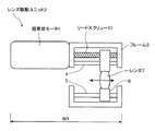
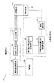
図1は、本発明の実施の一形態に係る超音波モータ1を用いるレンズ駆動ユニット2の概略構成図である。このレンズ駆動ユニット2は、DSC(デジタルスチルカメラ)やデジタルビデオカメラのズーム用、或いはDVDのピックアップレンズの収差補正用などに用いられ、厚さW1が、たとえば3〜5mmの小型の超音波モータである。円筒型の該超音波モータ1は、レンズユニットのフレーム3に取付けられ、その出力軸はリードスクリュー11となって直動レンズ送り機構を構成している。前記フレーム3にはまた、リードスクリュー11と並行に案内軸4,5が設けられており、それらの案内軸4,5上を摺動自在の案内部材6にレンズ7が保持されている。前記案内部材6には前記リードスクリュー11が噛合しており、該リードスクリュー11が回転することで、案内部材6、したがってレンズ7が、リードスクリュー11(超音波モータ1)および案内軸4,5の軸線(図の左右)方向に摺動変位する。
[Embodiment 1]
FIG. 1 is a schematic configuration diagram of a
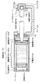
図2は、前記超音波モータ1の構造を示す軸線方向断面図である。この超音波モータ1は、圧電素子12aが高周波振動を行う振動体(ステータ)12と、前記振動体12に加圧接触し、前記高周波振動によって移動される移動体(ロータ)13と、前記振動体12を移動体13に押圧する加圧部材14と、それらを収納する有底円筒状のケース15と、前記移動体13に一体的またはかしめなどによって固着される前記リードスクリュー11と、前記リードスクリュー11を枢支する一対の軸受け部材16,17とを備えて構成される。
FIG. 2 is an axial sectional view showing the structure of the ultrasonic motor 1. The ultrasonic motor 1 includes a vibrating body (stator) 12 in which a
一方の軸受け部材16は、前記有底円筒状のケース15の開口端を閉塞し、前記リードスクリュー11の基端部11aをラジアル方向に支持し、他方の軸受け部材17は、フレームに取付けられたキャップ18に嵌り込む玉軸受けから成り、リードスクリュー11の遊端部11bに形成された凹面11cが嵌り込み、該遊端部11bをラジアル方向およびスラスト方向に支持する。
One bearing member 16 closes the open end of the bottomed
前記振動体12は、前記圧電素子12aに、移動体13側に接触部材12bを、その反対側に安定のための錘部材12cを備えて構成され、不図示の規制部材によって、ケース15に対して回転が規制されながら、移動体13との軸心が位置決めされて保持される。前記加圧部材14によって、振動体12は移動体13側(図中右方)に付勢され、接触部材12bが移動体13に押付けられる。これに対して、前記第2の軸受け部材17は、前記移動体13からリードスクリュー11への押圧力によるキャップ18からの反力を回転中心で受け止め、摩擦ロスを最小限に抑えられるようになっている。そして、前記キャップ18には、フレーム3との間にネジ18aが刻設されており、ネジ18aの回転量によってキャップ18が図中左右方向に移動し、押圧力を調整可能であり、その調整後、接着によって該キャップ18はフレーム3に固定される。
The vibrating
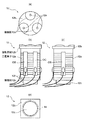
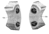
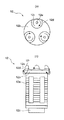
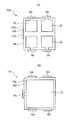
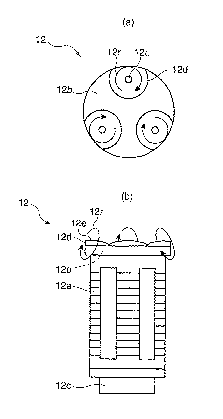
図3は、前記振動体12の六面図であり、(a)は上面図であり、(b)は正面図であり、(c)は側面図であり、(d)は底面図である。前述のとおり、振動体12は、積層型の圧電素子12aに、移動体13側に接触部材12bを、その反対側に錘部材12cを備え、それらが接着で結合されて構成される。接着剤には、剛性が高く、接着力の高いエポキシ系接着剤が使用される。接触部材12bは、耐摩耗性の高いアルミナ、ジルコニアなどによるセラミックスから成る。この接触部材12aは、3つの球面状の接触部12dが、該圧電素子12の周方向に等間隔(120°間隔)で形成され、前述の加圧部材14の押圧力によって、前記球面状の接触部12dの各頂点12eが移動体13に接触する。前記錘部材12cは、後述するような圧電素子12aの屈曲振動による基端側の振れを抑えるために、比重の高いタングステン、或いは銅や鉄系のタングステン合金などから成る。
FIG. 3 is a hexahedral view of the vibrating
図4は、前記積層型の圧電素子12aの一層当りの表裏両面を示す平面図および底面図である。各層12fは、PZT(チタン酸ジルコン酸鉛)から成る圧電層12gを挟んで、一方の面(図4(a))には、周方向に等間隔(90°間隔)に、図示しない駆動回路からの駆動信号が入力される駆動電極IA,IB,IC,IDが形成されるとともに、後述する該圧電素子の屈曲変位の最も大きいできるだけ外周側の領域を含むように、図示しない検出回路へ検出信号を出力する検出電極ISが形成され、他方の面(図4(b))には共通にベタのGND電極IGが形成される。これらの内部の電極IA,IB,IC,ID;ISおよびIGは、銀パラジウムの印刷などで形成され、積層される圧電層12gの層間で、前記駆動電極IA,IB,IC,IDおよび検出電極ISと、GND電極IGとが交互に形成される。
4A and 4B are a plan view and a bottom view showing both the front and back surfaces per layer of the multilayer
各層12fにおける電極IA,IB,IC,ID;ISおよびIGは、銀や金などをスクリーン印刷や蒸着などで形成された外部電極OA,OB,OC,OD;OSおよびOGによって、それぞれ共通に接続される。その外部電極OA,OB,OC,OD;OSおよびOGには、リード線やフレキシブル基板(図3の例ではリード線12h)などがハンダや導電性接着剤などで接合され、図示しない前記駆動回路や検出回路との間で駆動信号の入力や検出信号の出力が行われる。これら外部電極OA,OB,OC,OD;OSおよびOGの形成の関係で、圧電素子12aは、円柱または角柱状、特に四角柱が好ましい。前記各層12fならびにそれに形成された電極IA,IB,IC,ID;ISおよびIGは、積層後に、同方向に分極される。
Electrodes IA, IB, IC, ID; IS and IG in each
このように構成される圧電素子12aに対して、前記図示しない駆動回路から各駆動電極IA,IB,IC,IDとGND電極IGとの間に、前記等間隔(90°間隔)に対応する位相が互いに90°ずれた高周波の電界が与えられることで、各駆動電極IA,IB,IC,IDの領域は、90°位相がずれた伸縮振動を行う。そして、前記駆動信号の周波数を共振周波数に近付けると、該圧電素子12aには図5で示すような屈曲1次モードの振動が、前記90°位相がずれて励起される。
With respect to the
ここで、前述のように圧電素子12aの基端側には錘部材12cが取付けられるとともに、加圧部材14を介してケース15に固定されており、前記屈曲振動によって、先端側の接触部12dは公転運動(首振り振動)を行う。その結果、接触部12dの各頂点12eには、図6において参照符号12rで示すように、互いに位相が120°ずれた楕円振動が生成され、移動体13は、加圧部材14による押圧力とこの楕円振動12rとによって発生する摩擦力で、圧電素子12aの軸線回りに回転駆動される。前記図3と同様に、図6(a)は振動体12の上面図であり、図6(b)は正面図である。
Here, as described above, the
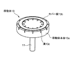
これに対して、図7は前記移動体13の斜視図であり、図8は前記移動体13と振動体12の接触部材12bとの接触部付近を展開して示す断面図である。なお、これらの図7および図8は、図3および図6とは上下関係が逆になっている。移動体13は、前記回転を取出す軸としての前記リードスクリュー11と、前記リードスクリュー11に固着される移動体本体13aと、前記移動体本体13aに積層されるカバー板13bとを備えて構成され、前記移動体本体13aのカバー板13b側の面において、半径方向に延びて周方向に等間隔に溝13cが形成されて構成される。そして、この溝13cが構造的に不均一な部分であり、検出域13dとなる。また、前記溝13cが形成されていない部分が構造的に均一な部分であり、駆動(通常)域13eとなる。
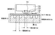
On the other hand, FIG. 7 is a perspective view of the moving body 13, and FIG. 8 is a cross-sectional view showing the vicinity of the contact portion between the moving body 13 and the
前記移動体13の作成は、ステンレスなどの金属から成る移動体本体13aに、機械加工やエッチングなどで溝13cを形成した後、ステンレスなどから成る薄板のカバー板13bを積層して行われる。前記カバー板13bには、耐摩耗性を向上させるために、窒化処理などが施されている。前記移動体本体13aへのカバー板13bの積層は、薄い接着層などで接合したり、スポット溶接などで結合することで行われ、移動体本体13aとカバー板13bとが、ずれなく一体で回転するようになっていればよい。このように構成することで、円筒の本体から出力軸が延びる通常の円筒型のモータと同じ形状の超音波モータ1を実現することができる。 The moving body 13 is produced by forming a groove 13c on a moving body main body 13a made of metal such as stainless steel by machining or etching, and then laminating a thin cover plate 13b made of stainless steel or the like. The cover plate 13b is subjected to nitriding treatment or the like in order to improve wear resistance. The cover plate 13b is stacked on the movable body 13a by joining with a thin adhesive layer or the like, or by spot welding or the like, and the movable body 13a and the cover plate 13b rotate integrally without deviation. It only has to come to do. By comprising in this way, the ultrasonic motor 1 of the same shape as the normal cylindrical motor from which an output shaft extends from a cylindrical main body is realizable.
上述のように構成される超音波モータ1において、前記図8は振動体12による移動体13の駆動の様子を模式的に示す図である。この図8を参照して、圧電素子12aを共振状態で駆動すると、接触部12dの頂点12eの楕円振動12rによって、移動体13は矢符13fで示す図の左方に移動(回転)され、前記頂点12eは移動体13の前記駆動域13eと検出域13dとの上を交互に通過する。ここで、溝13c、すなわち検出域13dは、頂点12eが同じタイミングで通過するように、すなわち120°毎の頂点12eに対して、検出域13dは、120°/n(nは整数で、図8ではn=4)毎に形成されている。
In the ultrasonic motor 1 configured as described above, FIG. 8 is a diagram schematically showing how the movable body 13 is driven by the vibrating
これによると、前記検出電極ISから出力される検出電圧の電圧と位相とは、それぞれ図9(a)および図9(b)で示すようになる。先ず図9(a)は、検出電圧の振幅値を示すもので、参照符号α11が駆動域13eに対応し、参照符号α12が検出域13dに対応している。検出電圧が最大値、すなわち歪が最大となる周波数f0が共振点で、その近傍で振幅値は大きく変化する。駆動は、その近傍の周波数f0’で行われている。検出域13dに入ると、共振周波数は低周波側のf0''へシフトし、圧電素子12aの歪量も少なくなる。これによって、振幅はΔVだけ低下する。これは、駆動域13eと検出域13dとで移動体13の接触部のばね定数が異なるためで、駆動域13eではカバー板13bの直下に移動体本体13aがあるので、接触点での剛性が高いのに対して、検出域13dではカバー板13bの直下は空隙であり、接触点での圧を該カバー板13bの弾性で支える構造となり、剛性が低下しているためである。なお、剛性=押圧している力/カバー板13bのたわみと定義する。こうして、圧電素子12aの共振周波数は低下し、駆動域13e上と検出域13d上とでは、圧電素子12aの共振状態が変化する。
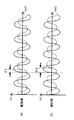
According to this, the voltage and phase of the detection voltage output from the detection electrode IS are as shown in FIGS. 9A and 9B, respectively. First, FIG. 9A shows the amplitude value of the detection voltage. Reference numeral α11 corresponds to the drive area 13e, and reference numeral α12 corresponds to the detection area 13d. The frequency f0 at which the detected voltage is the maximum value, that is, the distortion is the maximum, is the resonance point, and the amplitude value greatly changes in the vicinity thereof. Driving is performed at a frequency f0 'in the vicinity thereof. When entering the detection region 13d, the resonance frequency shifts to f0 ″ on the low frequency side, and the amount of distortion of the
また、図9(b)は、駆動信号に対する検出電圧の位相差を示すもので、参照符号α21が駆動域13eに対応し、参照符号α22が検出域13dに対応している。上述と同様の理由で、検出域13dに入り、共振周波数が低周波側へシフトすると、検出電圧の位相は、Δθだけ進む。図10は、その位相差を説明するための図であり、図10(a)は駆動域13eの通過中を示し、図10(b)は検出域13dの通過中を示す。共に、駆動信号を実線で、検出電圧を破線で示す。駆動域13eを通過中の偏差θ1に対して、剛性が低下する検出域13dの通過中は、偏差θ2は大きく、すなわち前記位相差(遅れ)は大きくなる。 FIG. 9B shows the phase difference of the detected voltage with respect to the drive signal. Reference numeral α21 corresponds to the drive area 13e, and reference numeral α22 corresponds to the detection area 13d. For the same reason as described above, when entering the detection region 13d and the resonance frequency is shifted to the low frequency side, the phase of the detection voltage advances by Δθ. 10A and 10B are diagrams for explaining the phase difference. FIG. 10A shows that the driving area 13e is passing, and FIG. 10B shows that the detecting area 13d is passing. In both cases, the drive signal is indicated by a solid line and the detection voltage is indicated by a broken line. The deviation θ2 is large during the passage of the detection area 13d where the rigidity is reduced, that is, the phase difference (delay) is large with respect to the deviation θ1 while passing through the drive area 13e.
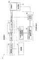
これを利用して、この超音波モータ1の駆動回路21,31は、それぞれ図11および図12で示すように構成することができる。図11は、前記検出電極ISの図9(a)で示す検出電圧の振幅値に基づいて位置検出を行うもので、図12は図9(b)で示す位相差に基づいて位置検出を行うものである。共に、駆動部22および位置検出部23,33ならびに制御部24,34を備えて構成される。
By utilizing this, the
前記駆動部22は、駆動回路21,31間で共通で、駆動電圧発生部25と、位相シフト部26と、フィルタ部27とを備えて構成される。駆動電圧発生部25は、圧電素子12aを駆動するのに充分なパワーの高周波信号を生成可能である。その高周波信号は、位相シフト部26に入力されて、前述のとおり、互いに位相が90°ずれた4相の駆動信号が作成され、高調波除去用のフィルタ27を介して、前記各駆動電極IA,IB,IC,IDとGND電極IGとの間に印加される。
The drive unit 22 is common between the
位置検出部23は、前記振幅検出を行うために、振幅検出部28、偏差算出部29および位置演算部30を備えて構成される。振幅検出部28は、前記検出電極ISから出力される検出電圧の振幅値(出力電圧)を検出し、偏差算出部29は、その振幅値と既知の理想振幅値(最適駆動の振幅値)との偏差を演算し、その演算結果から、位置演算部30は、移動体13の回転位置(回転量)や回転速度を検出する。制御部24は、前記駆動電圧発生部25に、正逆所望の方向の前記駆動信号を発生させる。
The position detection unit 23 includes an
これに対して、もう1つの位置検出部33は、前記位相検出を行うために、位相差検出部38、偏差算出部39および前記位置演算部40を備えて構成される。位相差検出部38は、前記検出電極ISから出力される検出電圧と、いずれかの相への駆動信号との位相差を検出し、偏差算出部39は、その位相差と所定の位相差(最適駆動の位相差)との偏差を演算し、その演算結果から、位置演算部40は、移動体13の回転位置(回転量)や回転速度を検出する。
On the other hand, the other position detection unit 33 includes a phase
上述のように構成される超音波モータ1において、注目すべきは、本実施の形態では、前記図7で示すように、移動体13において、前記カバー板13bが、該移動体13の移動方向に延びる帯状、すなわち超音波モータ1が前述のように円筒型であるので、環(リング)状に形成され、その幅以上に前記溝13cの長さが設定されていることである。 In the ultrasonic motor 1 configured as described above, it should be noted that in the present embodiment, as shown in FIG. 7, in the moving body 13, the cover plate 13 b is moved in the moving direction of the moving body 13. Since the ultrasonic motor 1 is cylindrical as described above, it is formed in a ring shape, and the length of the groove 13c is set to be greater than the width thereof.
したがって、溝13cが刻設されている部分では前記カバー板の下方は、必ずその溝13cによる空孔となっており、検出域13dとなる溝13c部分と、それ以外の非検出域となる駆動(通常)域13e部分とにおける移動体13の剛性の変化を、大きく取ることができるので、前記振幅検出部28や位相差検出部38では高いS/Nの検出信号を得ることができ、確実に位置検出を行うことができる。また、前記のように移動体13の回転位置や回転速度の検出が可能なセルフセンシング方式を実現するために形成される溝13cの通過を高感度に検出することができるので、前記検出域13dと非検出域である駆動(通常)域13eとの差を必要以上に大きくしなくてもよく、前記検出域13d(溝13c)の形成による駆動性能の低下を最小限に抑えることができる。具体的には、前記カバー板13bの厚さを厚く、または、溝13cの幅を狭くすることで、検出域13dの剛性を上げ、該検出域13dを接触部12dの頂点12eが通過する際の駆動性能の低下(楕円振動12rの減衰)を軽減することができる。
Therefore, in the portion where the groove 13c is formed, the lower portion of the cover plate is always a hole due to the groove 13c, and the groove 13c portion which becomes the detection region 13d and the drive which becomes the other non-detection region. Since the change in the rigidity of the moving body 13 in the (normal) area 13e can be greatly taken, the
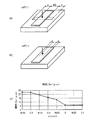
図13は、環(リング)状のカバー板13bの幅と、移動体本体13aにおける溝13cの長さとの関係を説明するための図である。超音波モータ1の径≒移動体本体13aの径が、たとえば3mmに対して、前記カバー板13bの幅W2は、0.5mm程度であり、これに対して、そのカバー板13bの端部から溝13cの端部までの隙間eが、図13(a)で示されるように+であるときには図13(c)で示すように前記検出域13dでの剛性は小さく一定であり、図13(b)で示されるように−であるときには図13(c)で示すように前記検出域13dでの剛性はその重なり量(eの値)が大きくなる程、大きくなってゆく。したがって、非検出域である駆動(通常)域13eでの剛性との差、すなわちS/Nは、前記隙間eが+であれば良好に得られることが理解される。 FIG. 13 is a diagram for explaining the relationship between the width of the ring-shaped cover plate 13b and the length of the groove 13c in the movable body main body 13a. The diameter W of the ultrasonic motor 1 ≈ the diameter of the movable body 13a is 3 mm, for example, and the width W2 of the cover plate 13b is about 0.5 mm, whereas from the end of the cover plate 13b When the gap e to the end of the groove 13c is + as shown in FIG. 13 (a), the rigidity in the detection area 13d is small and constant as shown in FIG. 13 (c). As shown by b), when it is-, as shown in FIG. 13C, the rigidity in the detection area 13d increases as the overlapping amount (value of e) increases. Accordingly, it is understood that the difference from the rigidity in the drive (normal) region 13e, which is a non-detection region, that is, S / N, can be obtained satisfactorily if the gap e is +.
表1には、前記図13(c)のグラフの基データを示す。すなわち、シミュレーション条件としては、溝13cの幅を0.2mmとし、カバー板13bの材料をステンレス、厚さを50μm、幅Wを0.5mmとし、押圧力を1Nとしたとき、前記重なり量(eの値)を変化させて、得られた撓み(μm)に前記押圧力から、剛性を求めた結果が前記図13(c)のグラフとなる。 Table 1 shows the basic data of the graph of FIG. That is, as a simulation condition, when the width of the groove 13c is 0.2 mm, the material of the cover plate 13b is stainless steel, the thickness is 50 μm, the width W is 0.5 mm, and the pressing force is 1 N, the overlap amount ( The value of e) is changed, and the result of obtaining the rigidity from the pressing force to the obtained deflection (μm) is the graph of FIG.
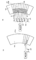
ここで、図14には、前記特許文献1と本実施の形態とにおける検出素子の構造の比較を模式的に示す。図14(a)は、特許文献1の構造を示すもので、圧電素子の変位によって弾性体101が共振し、圧電素子の変位を拡大するようになっている。圧電素子の外部には、検出用の電極が1層または2層形成されている。2層の場合は、位置分解能を上げるために、1層ずつ信号処理が行われるので、実質、この図14(a)の構成となる。
Here, FIG. 14 schematically shows a comparison of the structure of the detection element between Patent Document 1 and the present embodiment. FIG. 14A shows the structure of Patent Document 1. The
これに対して、本実施の形態では、圧電素子12a自身が共振変位を拡大し、しかも前述のように積層構造で、図14(b)で示すように、各圧電層12gに、駆動電極IA,IB,IC,IDと領域分割して検出電極ISとを形成し、しかもその検出電極ISを複数層に亘って同相位置に形成し、外部電極OSで並列に接続している。
On the other hand, in this embodiment, the
したがって、検出電極ISと圧電層12gを挟んで反対側の面に形成されるGND電極OSとの間の容量が等しく、各層12fの歪が等しいとすると、本実施の形態の方が、層数n倍の電荷が発生し、仮に、同量のノイズ(図中Qn)が発生したとすると、約層数n倍のS/Nを得ることができる。また、各層12f内の歪みの最も大きい部分に検出電極ISを形成するので、効率良く信号を取出すことができ、これによってもまた、感度が高くなる。
Therefore, assuming that the capacitance between the detection electrode IS and the GND electrode OS formed on the opposite surface across the
また、特許文献1の場合は、最も歪が大きくなる振動の腹は、棒状の弾性体101の中央部101aにあり、端部に設けられる圧電素子で検出できる歪の量は、比較的小さいものとなり、効率的に電荷を取り出せる構造となっていない。これに対して、本実施の形態では、圧電素子12a自身が共振し、その変位を拡大する構成であるとともに、前記屈曲1次モードの振動における2箇所の節(両端部)に挟まれた変形が最も大きい振動の腹となる中央部12k付近にも前記検出電極ISは形成されており、検出感度を高めることができ、また高分解能に対応することができる。
Further, in the case of Patent Document 1, the antinode of vibration with the largest strain is in the
さらに、特許文献1の構成では、別途に検出用の圧電層を設ける必要があり、振動体が長くなる。これに対して、本実施の形態では、駆動電極IA,IB,IC,IDと同一の面内で検出電極ISを分極配置しているので、振動体(圧電素子12a)を長くする必要はない。また、前記駆動電極IA,IB,IC,IDと検出電極ISとの双方を前記振動の腹の位置に配置できるので、効率良く振動を励起できるとともに、感度良く検出を行うことができる。
Furthermore, in the configuration of Patent Document 1, it is necessary to separately provide a piezoelectric layer for detection, and the vibrating body becomes long. On the other hand, in this embodiment, since the detection electrode IS is arranged in the same plane as the drive electrodes IA, IB, IC, ID, it is not necessary to lengthen the vibrating body (
さらにまた、特許文献1のように、検出電極を設けず、インピーダンス整合素子(コイル)を用いて圧電素子に掛かる電圧の変化を検出するような構成の場合、インピーダンス整合素子の周波数特性と振動体の周波数特性との双方によって、その変化の度合いが決まるので、個体差などによって、容易かつ安定に検出することは困難である。また、前記インピーダンス整合素子を付加する必要があり、回路規模が大きくなる。これに対して、本実施の形態では、前記個体差などに左右されることなく、安定した検出が可能である。 Further, as in Patent Document 1, in the case of a configuration in which a detection electrode is not provided and a change in voltage applied to the piezoelectric element is detected using an impedance matching element (coil), the frequency characteristics of the impedance matching element and the vibrating body The degree of change is determined by both of the frequency characteristics of the signal and it is difficult to detect it easily and stably due to individual differences. Further, it is necessary to add the impedance matching element, which increases the circuit scale. On the other hand, in the present embodiment, stable detection is possible without being influenced by the individual difference or the like.
上述の説明では、検出電極ISからの出力を電圧として取出したけれども、該検出電極ISとGND電極IGとの間を短絡する電流検出で出力を取出すこともできる。その場合、外部ノイズQnに対して、電圧による取出しよりも強くなるが、特許文献1では、電荷の発生量が小さいので、電流レベルが非常に小さく、検出が困難となる。 In the above description, the output from the detection electrode IS is taken out as a voltage. However, the output can also be taken out by current detection that short-circuits between the detection electrode IS and the GND electrode IG. In this case, the external noise Qn is stronger than the extraction by voltage, but in Patent Document 1, since the amount of generated charge is small, the current level is very small and detection is difficult.
[実施の形態2]
図15は、本発明の実施の他の形態に係る積層型の圧電素子12xの一層当りの表裏両面を示す平面図および底面図である。この圧電素子12xは、前述の図4で示す圧電素子12aに類似し、対応する部分には同一の参照符号を付して示し、その説明を省略する。注目すべきは、この圧電素子12xの各層12fは、PZT(チタン酸ジルコン酸鉛)から成る四角形の圧電層12gを挟んで、一方の面(図15(a))には図示しない駆動回路からの駆動信号が入力される駆動電極IA,IB,ICおよび図示しない検出回路へ検出信号を出力する検出電極ISが形成され、他方の面(図15(b))には共通にベタのGND電極IGが形成されることである。そして、前述の駆動回路21,31から各駆動電極IA,IB,ICとGND電極IGとの間に、前記各駆動電極IA,IB,ICの位置的な位相に対応する位相がずれた駆動信号(0°→90°→180°、または0°→−90°→−180°)による高周波の電界が与えられることで、圧電素子12xには振幅の方向差が生じるものの、前述の図5で示すような屈曲1次モードの振動を生じる。圧電素子12a,12xの楕円振動の励起には、最低3電極あれば可能であり、このように構成することで、出力は低下するが、外部電極OA,OB,OC;OGの数を減らすことができる。また、圧電素子12a,12xは、円柱状に形成されてもよい。
[Embodiment 2]
FIGS. 15A and 15B are a plan view and a bottom view showing both front and back surfaces per layer of a laminated
本発明の範囲は上述の実施形態によって限定されるべきではなく、特許請求の範囲の記載およびこれと均等なものの範囲内で様々な変形が可能なことは、当該技術分野における通常の知識を持つ者には明らかである。 The scope of the present invention should not be limited by the above-described embodiments, and various modifications are possible within the scope of the description of the claims and the equivalents thereof, and it has ordinary knowledge in the art. It is clear to the person.
ここで、特許第3060081号公報には、進行波型の超音波モータで、環状の摩擦材が示されている。しかしながら、この先行技術は、前記進行波型につき、進行波を伝える圧電振動子が大きな歯形を呈しているのに対して、本願発明では、接触部12dが小さく、カバー板13bが無いと、該接触部12dが溝13cに落ち込んでしまい、機能が著しく阻害される。したがって、本願発明とこの先行技術とは前提構成が異なり、先行技術でロータとステータとの間に介在される前記摩擦材は、トルク減少を改善するためのもので、少なくとも前記の歯の部分を覆っていればよく、環状の歯列に合わせて、前記摩擦材も環状に形成されていると思われる。そして、溝で切れている例(図7)もあることから、本実施の形態のカバー板13bおよび溝13cのように、形状について格別に考慮されているものではない。
Here, in Japanese Patent No. 3060081, an annular friction material is shown as a traveling wave type ultrasonic motor. However, in the prior art, the piezoelectric vibrator for transmitting traveling waves has a large tooth profile for the traveling wave type, whereas in the present invention, if the
1 超音波モータ
2 レンズ駆動ユニット
3 フレーム
6 案内部材
7 レンズ
11 リードスクリュー
12 振動体(ステータ)
12a,12x 圧電素子
12b 接触部材
12c 錘部材
12d 接触部
12e 頂点
12g 圧電層
13 移動体(ロータ)
13a 移動体本体
13b カバー板
13c 溝
13d 検出域
13e 駆動(通常)域
14 加圧部材
15 ケース
16,17 軸受け部材
21,31 駆動回路
22 駆動部
23,33 位置検出部
24,34 制御部
25 駆動電圧発生部
26 位相シフト部
27 フィルタ部
28 振幅検出部
29,39 偏差算出部
30,40 位置演算部
38 位相差検出部
IA,IB,IC,ID 駆動電極
IG GND電極
IS 検出電極
OA,OB,OC,OD;OS;OG 外部電極
DESCRIPTION OF SYMBOLS 1
12a,
13a Mobile body 13b Cover plate 13c Groove 13d Detection area 13e Drive (normal)
Claims (6)
前記移動体は、前記溝が刻設される移動体本体に、それを覆うカバー板を備えて成り、前記カバー板は、該移動体の移動方向に延びる帯状に形成され、その幅以上に前記溝の長さが設定されていることを特徴とする超音波モータ。 The piezoelectric element includes a vibrating body that performs high-frequency vibration, a moving body that is in pressure contact with the vibrating body and moved by the high-frequency vibration, and a detection unit. In order to change the vibration state of the vibrating body, the groove extends in a direction orthogonal to the moving direction of the moving body, and grooves are engraved at a predetermined interval in the moving direction of the moving body. In the ultrasonic motor that makes it possible to detect the position of the moving body by detecting the change in the vibration state of the vibrating body due to the passage of the contact portion by the detection unit,
The movable body includes a movable body main body in which the groove is engraved, and a cover plate that covers the movable body, and the cover plate is formed in a strip shape extending in a moving direction of the movable body, An ultrasonic motor characterized in that a groove length is set.
前記移動体本体は円板状に形成され、該移動体本体の中央には出力軸が固着されていることを特徴とする請求項1記載の超音波モータ。 The piezoelectric element has a cylindrical or prismatic shape in which a plurality of piezoelectric layers formed with circumferentially divided drive electrodes are stacked, and each drive electrode corresponds to a positional displacement amount of the drive electrode from a drive circuit. By applying a high-frequency electric field whose phases are shifted from each other, the tip of the vibrating body revolves, and the moving body is rotated around the axis of the vibrating body by a contact member attached to the tip of the vibrating body. And
2. The ultrasonic motor according to claim 1, wherein the movable body is formed in a disc shape, and an output shaft is fixed to the center of the movable body.
前記カバー板は、環状に形成されていることを特徴とする請求項2記載の超音波モータ。 The grooves are formed radially on the mobile body,
The ultrasonic motor according to claim 2, wherein the cover plate is formed in an annular shape.
前記各駆動電極に対して、前記駆動回路から、位相が互いに90°ずれた高周波の電界が与えられることで、前記振動体には屈曲1次モードの振動を位相がずれて生じ、
前記検出電極は、前記屈曲1次モードの振動における2箇所の節に挟まれた振動の腹の領域を含むことを特徴とする請求項4記載の超音波モータ。 Each of the piezoelectric layers is formed with four drive electrodes in the circumferential direction,
A high-frequency electric field whose phase is shifted from each other by 90 ° is applied from the drive circuit to each of the drive electrodes, thereby causing vibration of the bending primary mode in the vibrator to be out of phase.
5. The ultrasonic motor according to claim 4, wherein the detection electrode includes a vibration antinode region sandwiched between two nodes in the vibration of the bending primary mode.
Priority Applications (1)
| Application Number | Priority Date | Filing Date | Title |
|---|---|---|---|
| JP2008313850A JP2010141979A (en) | 2008-12-10 | 2008-12-10 | Ultrasonic motor |
Applications Claiming Priority (1)
| Application Number | Priority Date | Filing Date | Title |
|---|---|---|---|
| JP2008313850A JP2010141979A (en) | 2008-12-10 | 2008-12-10 | Ultrasonic motor |
Publications (1)
| Publication Number | Publication Date |
|---|---|
| JP2010141979A true JP2010141979A (en) | 2010-06-24 |
Family
ID=42351599
Family Applications (1)
| Application Number | Title | Priority Date | Filing Date |
|---|---|---|---|
| JP2008313850A Pending JP2010141979A (en) | 2008-12-10 | 2008-12-10 | Ultrasonic motor |
Country Status (1)
| Country | Link |
|---|---|
| JP (1) | JP2010141979A (en) |
Cited By (4)
| Publication number | Priority date | Publication date | Assignee | Title |
|---|---|---|---|---|
| JP2013046507A (en) * | 2011-08-25 | 2013-03-04 | Canon Inc | Vibration type driver, and manufacturing method of mobile body thereof |
| JP2014063994A (en) * | 2012-08-27 | 2014-04-10 | Canon Inc | Piezoelectric material, piezo electric element, and electronic apparatus |
| CN111542403A (en) * | 2017-11-10 | 2020-08-14 | 超声超音波有限公司 | Ultrasonic transducer |
| JPWO2022113510A1 (en) * | 2020-11-24 | 2022-06-02 |
-
2008
- 2008-12-10 JP JP2008313850A patent/JP2010141979A/en active Pending
Cited By (6)
| Publication number | Priority date | Publication date | Assignee | Title |
|---|---|---|---|---|
| JP2013046507A (en) * | 2011-08-25 | 2013-03-04 | Canon Inc | Vibration type driver, and manufacturing method of mobile body thereof |
| JP2014063994A (en) * | 2012-08-27 | 2014-04-10 | Canon Inc | Piezoelectric material, piezo electric element, and electronic apparatus |
| US9780293B2 (en) | 2012-08-27 | 2017-10-03 | Canon Kabushiki Kaisha | Piezoelectric material, piezoelectric element, and electronic apparatus |
| CN111542403A (en) * | 2017-11-10 | 2020-08-14 | 超声超音波有限公司 | Ultrasonic transducer |
| CN111542403B (en) * | 2017-11-10 | 2022-08-23 | 超声超音波有限公司 | Ultrasonic transducer |
| JPWO2022113510A1 (en) * | 2020-11-24 | 2022-06-02 |
Similar Documents
| Publication | Publication Date | Title |
|---|---|---|
| JP6056224B2 (en) | Vibration wave motor | |
| US20250364924A1 (en) | Lens barrel and imaging device | |
| JP2002112562A (en) | Driving unit | |
| JP2010141979A (en) | Ultrasonic motor | |
| US11594985B2 (en) | Lens barrel and imaging device | |
| US8035906B2 (en) | Vibration actuator, lens barrel and camera | |
| JP2009189219A (en) | Vibration actuator, lens barrel, camera | |
| JP3526298B2 (en) | Vibrating body and vibration wave driving device | |
| US7825566B2 (en) | Ultrasonic actuator and method for manufacturing piezoelectric deformation portion used in the same | |
| KR101653826B1 (en) | Ultrasonic motor and method for manufacturing the ultrasonic motor | |
| JP5262170B2 (en) | Lens barrel, camera | |
| JP6961383B2 (en) | Vibration type actuator | |
| JP2010074912A (en) | Ultrasonic motor | |
| CN102545689B (en) | Vibrational wave motor, lens barrel and camera | |
| JP2009201322A (en) | Vibrating actuator, manufacturing method therefor, lens barrel, and camera | |
| WO2010041533A1 (en) | Ultrasonic motor and piezoelectric oscillator | |
| JP5541281B2 (en) | Vibration actuator, lens barrel and camera | |
| WO2010067774A1 (en) | Ultrasonic motor | |
| US20080061654A1 (en) | Ultrasonic actuator and manufacturing method of vibration member thereof | |
| JP2011024312A (en) | Ultrasonic motor | |
| JP6221521B2 (en) | Vibration wave motor and optical equipment | |
| JP2009055779A (en) | Ultrasonic actuator, magnetic recording apparatus | |
| JP2018018095A (en) | Vibration wave motor and optical apparatus | |
| JP2018191382A (en) | Vibration actuator and electronic equipment | |
| JP2001190080A (en) | Vibration actuator |