JP2010268221A - Lighting device, image reader and image forming apparatus - Google Patents
Lighting device, image reader and image forming apparatus Download PDFInfo
- Publication number
- JP2010268221A JP2010268221A JP2009117774A JP2009117774A JP2010268221A JP 2010268221 A JP2010268221 A JP 2010268221A JP 2009117774 A JP2009117774 A JP 2009117774A JP 2009117774 A JP2009117774 A JP 2009117774A JP 2010268221 A JP2010268221 A JP 2010268221A
- Authority
- JP
- Japan
- Prior art keywords
- light emitting
- emitting element
- lens
- light
- diffusion plate
- Prior art date
- Legal status (The legal status is an assumption and is not a legal conclusion. Google has not performed a legal analysis and makes no representation as to the accuracy of the status listed.)
- Pending
Links
Images


Abstract
Description
本発明は、複数の発光素子を直線状に配列した照明装置、この照明装置を備えた画像読取装置、及びこの画像読取装置を搭載した画像形成装置に関する。 The present invention relates to an illuminating device in which a plurality of light emitting elements are linearly arranged, an image reading device provided with the illuminating device, and an image forming apparatus equipped with the image reading device.
複数の発光素子(LED素子)を列状に配置した照明装置を備えた画像読取装置においては、隣り合うLED素子の間で、光の照度ムラ(LED素子に対抗する部分では照度が高く、LED素子とLED素子との間では照度が低くなる現象)が発生する。また、原稿からの反射光を読み取る場合、読み取り部分に画像読取素子(例えばCCD等)とレンズを用いた縮小光学系では、レンズの特性により、レンズ中央部の透過光は明るくレンズ端部の透過光は暗くなる。このため、それに合わせて画像読取素子からの出力信号に電気的補正(シェーディング補正)を行う必要がある。 In an image reading apparatus including an illuminating device in which a plurality of light emitting elements (LED elements) are arranged in a row, the illuminance unevenness of light between adjacent LED elements (the illuminance is high in a portion opposed to the LED elements, and the LED The phenomenon that the illuminance decreases between the element and the LED element occurs. In addition, when reading reflected light from a document, in a reduction optical system using an image reading element (for example, a CCD) and a lens in the reading portion, the transmitted light at the center of the lens is bright and transmitted at the end of the lens due to the characteristics of the lens. The light becomes dark. For this reason, it is necessary to perform electrical correction (shading correction) on the output signal from the image reading element accordingly.
このような問題に対し、例えば特許文献1には、パネル裏面に配置した光源よりの光を表面側へ透過させて視認し得るようにしたパネル面において、パネル裏面の光源とパネルとの間に、光源よりの中心距離が遠ざかるほど不透光部分は小さく、逆に透光部分は大きくなる縞状パターンを印刷して成る透光板を配置したパネル面の照度均一化構造が開示されている。この特許文献1記載のものは、パネル裏面の光源よりの光を、パネル裏面に均一に照射させることを目的として創案されたものであり、パネル裏面の光源とパネルとの間に透光板を配置することで目的を達成している。 For such a problem, for example, in Patent Document 1, in a panel surface that allows light from a light source disposed on the back surface of the panel to be transmitted to the front surface side for visual recognition, between the light source on the back surface of the panel and the panel. A panel surface illuminance uniforming structure is disclosed in which a translucent plate is formed by printing a striped pattern in which the non-transparent portion is smaller and the translucent portion is larger as the center distance from the light source is longer. . The thing of this patent document 1 was invented in order to irradiate the light from the light source of a panel back surface uniformly to a panel back surface, and a translucent board is provided between the light source of a panel back surface, and a panel. The purpose is achieved by arranging.
また、特許文献2には、複数個のLED発光素子を列設して形成されたLEDアレイを備えて原稿に向け光を照射する光源と、LEDアレイと前記原稿との間に配置され前記光照射体から射出される光を拡散する拡散部材とを備え、拡散部材とLEDアレイからの距離Lを、列設されたLED素子の間隔をP、前記LED素子の発光分布での照射面における相対光度が0.5となる角度をθとしたとき、L=(P/2)tanθとなるように配置した照明装置、画像読取装置及び画像形成装置が開示されている。この特許文献2記載のものは、点光源を主走査方向にアレイ状に並べた光源の場合でも、光を効率よく原稿面に照射し、かつ、正反射光が撮像素子に入った際に画像の劣化を低減させることを目的として創案されたものであり、LEDアレイと原稿との間に配置する拡散部材のLED発光素子からの距離を、上記関係式を満たすように配置することで目的を達成している。 Japanese Patent Application Laid-Open No. 2004-228688 includes a light source that includes an LED array formed by arranging a plurality of LED light emitting elements in a line and irradiates light on a document, and is disposed between the LED array and the document. A diffusing member that diffuses light emitted from the irradiating body, a distance L from the diffusing member and the LED array, a distance between the LED elements arranged in a row, and a relative light emitting surface of the light emitting distribution of the LED elements. An illuminating device, an image reading device, and an image forming device arranged so that L = (P / 2) tan θ, where θ is the angle at which the luminous intensity becomes 0.5, are disclosed. Even in the case of a light source in which point light sources are arranged in an array in the main scanning direction, the image described in Patent Document 2 is an image obtained when light is efficiently applied to a document surface and specularly reflected light enters an image sensor. It was created for the purpose of reducing the deterioration of the LED, and the purpose is to arrange the distance from the LED light emitting element of the diffusion member arranged between the LED array and the original so as to satisfy the above relational expression. Have achieved.
上記特許文献1,2記載のものによれば、光源(LED素子)による照度ムラを無くすことは可能である。 According to those described in Patent Documents 1 and 2, it is possible to eliminate unevenness in illuminance due to the light source (LED element).
一方、原稿からの反射光を読み取る場合、読み取り部分に画像読取素子(例えばCCD)とレンズを用いた縮小光学系では、レンズの特性により、レンズ中央部の透過光は明るくレンズ端部の透過光は暗くなる。このため、それに合わせて画像読取素子からの出力信号に電気的補正(シェーディング補正)を行う必要があるが、上記引用文献1,2記載のものでは、透光板や拡散部材はあくまで照度ムラを無くすためのものであり、このような出力信号のシェーディング補正までは考慮されていない。そのため、シェーディング補正については別途対応する必要があった。 On the other hand, when reading reflected light from a document, in a reduction optical system using an image reading element (for example, a CCD) and a lens in the reading part, the transmitted light at the center of the lens is bright due to the characteristics of the lens, and the transmitted light at the end of the lens. Becomes darker. For this reason, it is necessary to perform electrical correction (shading correction) on the output signal from the image reading element in accordance with this. This is to eliminate the shading correction of the output signal. Therefore, it is necessary to deal with shading correction separately.
本発明はかかる問題点を解決すべく創案されたもので、その目的は、複数の発光素子の前方に配置される拡散板に、少なくとも縮小光学系に用いられるレンズの特性を打ち消すように印刷パターンを形成することで、レンズ特性による読取画像の劣化を防止するとともに、併せて発光素子による照度ムラも解消した照明装置、画像読取装置及び画像形成装置を提供することにある。 The present invention was devised to solve such problems, and an object of the present invention is to provide a printed pattern so as to cancel at least characteristics of a lens used in a reduction optical system on a diffusion plate arranged in front of a plurality of light emitting elements. It is an object of the present invention to provide an illumination device, an image reading device, and an image forming apparatus that prevent deterioration of a read image due to lens characteristics and eliminate illuminance unevenness due to a light emitting element.
上記課題を解決するため、本発明の照明装置は、複数の発光素子を列状に配置した照明装置であって、前記発光素子の前方に光学系レンズのレンズ特性に対応した拡散板が配置されていることを特徴としている。ここで、レンズ特性とは、撮像素子に集光する光学系に使用されるレンズの特性(主に縮小光学系に使用されるレンズの特性)のことである。 In order to solve the above problems, the illumination device of the present invention is an illumination device in which a plurality of light emitting elements are arranged in a row, and a diffusion plate corresponding to the lens characteristics of the optical system lens is disposed in front of the light emitting elements. It is characterized by having. Here, the lens characteristic is a characteristic of a lens used in an optical system that focuses light on an image sensor (mainly a characteristic of a lens used in a reduction optical system).
このように、縮小光学系のレンズ特性に対応した拡散板を用いることにより、原稿からの反射光を、主走査方向に対してほぼ均一な照度レベルの光に補正して画像読取素子(例えば、CCD等)に導くことが可能となる。これにより、画像読取素子の出力を補正する必要が無くなる。すなわち、レンズ中央部とレンズ端部とに対応する位置から出てくる画像読取素子の出力を同等にすることができる。 In this way, by using the diffusion plate corresponding to the lens characteristics of the reduction optical system, the reflected light from the original is corrected to light having a substantially uniform illuminance level in the main scanning direction, and an image reading element (for example, CCD etc.). This eliminates the need to correct the output of the image reading element. That is, the output of the image reading element coming out of the position corresponding to the lens center and the lens end can be made equal.
また、本発明の照明装置によれば、前記発光素子の前方に当該発光素子による照度ムラに対応した拡散板が配置されていることを特徴としている。 Moreover, according to the illuminating device of this invention, the diffusion plate corresponding to the illumination intensity nonuniformity by the said light emitting element is arrange | positioned ahead of the said light emitting element, It is characterized by the above-mentioned.
すなわち、縮小光学系のレンズ特性に対応した拡散板に加え、発光素子による照度ムラに対応した拡散板をさらに配置することで、ほぼ均一な照度レベルの光を原稿に照射することができ、かつ、主走査方向に対してほぼ均一な照度レベルの光に補正して画像読取素子に導くことが可能となる。これにより、画像読取素子の出力を補正する必要が無くなる。すなわち、レンズ中央部とレンズ端部とに対応する位置から出てくる画像読取素子の出力を同等にすることができる。 That is, in addition to the diffuser plate corresponding to the lens characteristics of the reduction optical system, by further disposing the diffuser plate corresponding to the illuminance unevenness due to the light emitting element, it is possible to irradiate the original with light having a substantially uniform illuminance level, and Thus, the light can be corrected to light having a substantially uniform illuminance level in the main scanning direction and guided to the image reading element. This eliminates the need to correct the output of the image reading element. That is, the output of the image reading element coming out of the position corresponding to the lens center and the lens end can be made equal.
ここで、前記拡散板は、透明基材の上に、縮小光学系のレンズ特性に対応した不透光な印刷パターン、及び/又は発光素子による照度ムラに対応した不透光な印刷パターンが形成されたものである。不透光なインクを用いてパターンを印刷することで、手軽で安価に拡散板を作成することができる。 Here, the diffuser plate is formed on a transparent substrate with an opaque printing pattern corresponding to the lens characteristics of the reduction optical system and / or an opaque transmission pattern corresponding to illuminance unevenness due to the light emitting element. It has been done. By printing a pattern using light-impermeable ink, a diffusion plate can be easily and inexpensively created.
ここで、配置される拡散板が1枚の場合、前記拡散板は、透明基材の一方の面にレンズ特性に対応した不透光な印刷パターンが形成され、他方の面に前記発光素子の照度ムラに対応した不透光な印刷パターンが形成された構成としてもよい。 Here, when one diffusion plate is arranged, the diffusion plate is formed with a translucent print pattern corresponding to the lens characteristics on one surface of the transparent substrate, and on the other surface of the light emitting element. It is good also as a structure in which the opaque printing pattern corresponding to illumination intensity nonuniformity was formed.
また、配置される拡散板が1枚の場合、前記拡散板は、透明基材の一方の面に、レンズ特性に対応した不透光な印刷パターンと、前記発光素子の照度ムラに対応した不透光な印刷パターンとが合わせて(重ねて)形成された構成としてもよい。 In addition, when only one diffusion plate is disposed, the diffusion plate has a non-transparent print pattern corresponding to lens characteristics on one surface of the transparent base material and an unevenness corresponding to illuminance unevenness of the light emitting element. It is good also as a structure in which the translucent printing pattern was united (overlaid).
本発明の照明装置を画像読取装置に搭載した場合、画像読取装置では、光照射側の特性(複数の発光素子からなるLEDアレイの照度ムラ)に対応したパターンと、光受光側の特性(縮小光学系のレンズ、及びCCD等の画像読取素子によるシェーディング特性)に対応したパターンとを分離して(個別に)作成することで、印刷するパターンの数を減らすことができる。 When the illumination device of the present invention is mounted on an image reading device, the image reading device has a pattern corresponding to the characteristics on the light irradiation side (illuminance unevenness of the LED array composed of a plurality of light emitting elements) and the characteristics on the light receiving side (reduction). The number of patterns to be printed can be reduced by creating (separately) the pattern corresponding to the lens of the optical system and the pattern corresponding to the shading characteristics by the image reading element such as a CCD.
例えば、同一読み取りサイズの画像読取装置が複数機種あった場合を想定し、画像読取装置に使用されるLEDアレイが3種、縮小光学系のレンズが3種であったと仮定すると、これらの種類に応じたパターンを拡散板の表裏両面に印刷する場合、印刷パターンとしては3×3の9種(全ての組み合わせ分)が必要となりる。一方、これらのパターンを拡散板の一つの面に個別に印刷する場合、印刷パターンとしては3+3の6種で対応することが可能となる。 For example, assuming that there are a plurality of types of image reading apparatuses having the same reading size, and assuming that there are three types of LED arrays used in the image reading apparatus and three types of lenses of the reduction optical system, these types are used. When printing the corresponding pattern on both the front and back sides of the diffusion plate, 9 types of 3 × 3 (for all combinations) are required as printing patterns. On the other hand, when these patterns are individually printed on one surface of the diffusion plate, it is possible to cope with six types of 3 + 3 as print patterns.
具体的に説明すると、LEDアレイとして、配置ピッチや照度ムラが違うA,B,Cの3種あり、レンズとして、端部と中央部の照度差に違いのあるa,b,cの3種あったとすると、それぞれの組み合わせのパターンを1枚の拡散板の表裏両面に印刷する場合には、Aa,Ab,Ac,Ba,Bb,Bc,Ca,Cb,Ccの9種類の組み合わせパターンが印刷された9枚の拡散板が必要となる。 More specifically, there are three types of LED arrays, A, B, and C, which have different arrangement pitches and uneven illuminance, and three types of lenses, a, b, and c, that have different illuminance differences between the end and the center. Assuming that there are nine combinations of patterns Aa, Ab, Ac, Ba, Bb, Bc, Ca, Cb, and Cc when printing each combination pattern on the front and back sides of a single diffusion plate, Nine diffuser plates are required.
一方、1枚の拡散板の一面に各パターンを個別に印刷する場合は、表面用のA,B,Cと、裏面用のa,b,cの6種類のパターンが個別に印刷された6枚の拡散板で全ての組み合わせの画像読取装置を実現することが可能となる。 On the other hand, when each pattern is individually printed on one surface of one diffusion plate, six types of patterns A, B, and C for the front surface and a, b, and c for the back surface are individually printed 6 All combinations of image reading apparatuses can be realized with a single diffusion plate.
また、本発明によれば、前記拡散板は、前記発光素子と原稿との間の光路に配置された構成とすることができる。この配置構成の場合、レンズ特性に対応したパターンが一面に印刷された拡散板と、発光素子による照度ムラに対応したパターンが一面に印刷された拡散板の2枚の拡散板を配置する場合と、表裏両面にレンズ特性に対応したパターンと発光素子による照度ムラに対応したパターンとが印刷された(若しくは、同一面にレンズ特性に対応したパターンと発光素子による照度ムラに対応したパターンとが合わせて(重ねて)印刷された)1枚の拡散板を配置する場合とがある。 Further, according to the present invention, the diffusing plate can be arranged in an optical path between the light emitting element and the document. In the case of this arrangement configuration, there are two diffuser plates, one is a diffuser plate printed with a pattern corresponding to lens characteristics on one side, and the other is a diffuser plate printed with a pattern corresponding to illuminance unevenness by the light emitting element on one side. The pattern corresponding to the lens characteristics and the pattern corresponding to the illuminance unevenness by the light emitting element are printed on both the front and back surfaces (or the pattern corresponding to the lens characteristic and the pattern corresponding to the illuminance unevenness by the light emitting element are combined on the same surface. In some cases, a single diffuser plate (printed in layers) is disposed.
一方、レンズ特性に対応したパターンが一面に印刷された拡散板と、発光素子による照度ムラに対応したパターンが一面に印刷された拡散板の2枚の拡散板を配置する場合には、発光素子の照度ムラに対応した拡散板を前記発光素子と原稿との間の光路に配置し、前記レンズ特性に対応した拡散板を原稿からの反射光の光路に配置した構成とすることができる。 On the other hand, when two diffuser plates, a diffuser plate printed with a pattern corresponding to lens characteristics on one side and a diffuser plate printed with a pattern corresponding to illuminance unevenness by the light emitting element on one side, are arranged. The diffuser plate corresponding to the illuminance unevenness can be arranged in the optical path between the light emitting element and the original, and the diffuser plate corresponding to the lens characteristic can be arranged in the optical path of the reflected light from the original.
次に、本発明に係わる印刷パターンについて具体的に説明する。 Next, the printing pattern according to the present invention will be specifically described.
本発明によれば、発光素子の照度ムラに対応した印刷パターンとして、縞模様(具体的には、縦縞模様)状のパターンとし、前記発光素子の直上に対応する部分の縞が太く、前記直上に対応する部分から離れるに従って縞が徐々に細くなるように印刷された構成とすることができる。 According to the present invention, the printed pattern corresponding to the illuminance unevenness of the light emitting element is a striped pattern (specifically, a vertical stripe pattern), and the stripe corresponding to the portion directly above the light emitting element is thick. It can be set as the structure printed so that a fringe may become thin gradually as it leaves | separates from the part corresponding to.
また、発光素子の照度ムラに対応した印刷パターンとして、前記発光素子の直上に対応する部分のインク濃度が濃く、前記直上に対応する部分から離れるに従って徐々にインク濃度が薄くなるように印刷された構成とすることができる。 In addition, the printed pattern corresponding to the uneven illuminance of the light emitting element was printed such that the ink density in the portion corresponding directly above the light emitting element was high, and the ink concentration gradually decreased as the distance from the portion corresponding to the light above was increased. It can be configured.
また、発光素子の照度ムラに対応した印刷パターンとして、濃度の薄いインクを複数回重ねて印刷した構成とし、前記発光素子の直上に対応する部分の印刷回数が多く、前記直上に対応する部分から離れるに従って徐々に印刷回数が少なくなるように印刷された構成とすることができる。 In addition, as a print pattern corresponding to the illuminance unevenness of the light emitting element, it is configured such that light ink with a low density is printed a plurality of times, and the number of times of printing of the part corresponding directly above the light emitting element is large. It can be set as the structure printed so that the frequency | count of printing may decrease gradually as it leaves | separates.
また、本発明によれば、レンズ特性に対応した印刷パターンとして、レンズ中央部に対応する部分のインク濃度が濃く、前記レンズ中央部に対応する部分から離れるに従ってインク濃度が徐々に薄くなるように印刷された構成とすることができる。 Further, according to the present invention, as the print pattern corresponding to the lens characteristics, the ink density in the portion corresponding to the lens central portion is high, and the ink concentration is gradually decreased as the distance from the portion corresponding to the lens central portion is increased. It can be a printed configuration.
また、レンズ特性に対応した印刷パターンとして、レンズ中央部に対応する部分のインクドットが高密度、前記レンズ中央部に対応する部分から離れるに従ってインクドットが徐々に低密度となるように印刷された構成とすることができる。 Also, as a print pattern corresponding to the lens characteristics, the ink dots in the portion corresponding to the lens center portion were printed with high density, and the ink dots were gradually reduced in density as the distance from the portion corresponding to the lens center portion was increased. It can be configured.
なお、本発明では、このような構成の照明装置を画像読取装置に備えることで、原稿に対して主走査方向に照度ムラの無い(若しくは少ない)ほぼ均一な照度レベルの光を照射し、原稿の反射光に対してシェーディング補正を行って画像読取素子に導くことができる画像読取装置を実現することができる。 In the present invention, the illumination device having such a configuration is provided in the image reading device, so that the original is irradiated with light having a substantially uniform illuminance level with no (or little) illuminance unevenness in the main scanning direction. Therefore, it is possible to realize an image reading apparatus capable of performing shading correction on the reflected light and guiding the reflected light to the image reading element.
また、この画像読取装置を画像形成装置に搭載することで、原稿の読み取り品質に優れた画像形成装置を実現することができる。 Further, by mounting the image reading apparatus on the image forming apparatus, an image forming apparatus having excellent document reading quality can be realized.
本発明は上記のように構成したので、レンズ特性に対応した拡散板を用いることにより、原稿からの反射光を、主走査方向に対してほぼ均一な光量に補正することができる。すなわち、レンズ中央部とレンズ端部とに対応する位置から出てくる画像読取素子の出力を同等にすることができる。 Since the present invention is configured as described above, the reflected light from the original can be corrected to a substantially uniform light quantity in the main scanning direction by using the diffusion plate corresponding to the lens characteristics. That is, the output of the image reading element coming out of the position corresponding to the lens center and the lens end can be made equal.
以下、本発明に係る一実施形態について図面を参照しながら説明する。なお、以下の実施形態は、本発明を具体化した一例であって、本発明の技術的範囲を限定する性格のものではない。 Hereinafter, an embodiment according to the present invention will be described with reference to the drawings. In addition, the following embodiment is an example which actualized this invention, Comprising: The thing of the character which limits the technical scope of this invention is not.
図1は、本発明に係る照明装置の一実施形態を適用した画像読取装置100を備えた画像形成装置Dを概略的に示す側面図である。
FIG. 1 is a side view schematically showing an image forming apparatus D including an
図1に示す画像形成装置Dは、原稿G(後述する図2等参照)の画像を読み取る画像読取装置100と、この画像読取装置100により読み取られた原稿Gの画像又は外部から受信した画像をカラーもしくは単色で普通紙等の記録シートに記録形成する装置本体D’とを備えている。
An image forming apparatus D shown in FIG. 1 reads an image of an original G (see FIG. 2 described later) and an image of the original G read by the
[画像形成装置の全体構成の説明]
画像形成装置Dの装置本体D’は、露光装置1、現像装置2(2a,2b,2c,2d)、像担持体として作用する感光体ドラム3(3a,3b,3c,3d)、帯電器5(5a,5b,5c,5d)、クリーナ装置4(4a,4b,4c,4d)、転写部として作用する中間転写ローラ6(6a,6b,6c,6d)を含む中間転写ベルト装置8、定着装置12、シート搬送装置50、給紙部として作用する給紙トレイ10、及び排紙部として作用する排紙トレイ15を備えている。
[Description of Overall Configuration of Image Forming Apparatus]
The apparatus main body D ′ of the image forming apparatus D includes an exposure apparatus 1, a developing apparatus 2 (2a, 2b, 2c, 2d), a photosensitive drum 3 (3a, 3b, 3c, 3d) that functions as an image carrier, and a charger. 5 (5a, 5b, 5c, 5d), cleaner device 4 (4a, 4b, 4c, 4d), intermediate
画像形成装置Dの装置本体D’において扱われる画像データは、ブラック(K)、シアン(C)、マゼンタ(M)、イエロー(Y)の各色を用いたカラー画像に応じたもの、又は単色(例えばブラック)を用いたモノクロ画像に応じたものである。従って、現像装置2(2a,2b,2c,2d)、感光体ドラム3(3a,3b,3c,3d)、帯電器5(5a,5b,5c,5d)、クリーナ装置4(4a,4b,4c,4d)、中間転写ローラ6(6a,6b,6c,6d)は各色に応じた4種類の画像を形成するようにそれぞれ4個ずつ設けられ、それぞれの末尾符号a〜dのうち、aがブラックに、bがシアンに、cがマゼンタに、dがイエローに対応付けられて、4つの画像ステーションが構成されている。以下、末尾符号a〜dは省略して説明する。 The image data handled in the apparatus main body D ′ of the image forming apparatus D is data corresponding to a color image using each color of black (K), cyan (C), magenta (M), yellow (Y), or a single color ( For example, it corresponds to a monochrome image using black). Accordingly, the developing device 2 (2a, 2b, 2c, 2d), the photosensitive drum 3 (3a, 3b, 3c, 3d), the charger 5 (5a, 5b, 5c, 5d), and the cleaner device 4 (4a, 4b, 4c, 4d) and four intermediate transfer rollers 6 (6a, 6b, 6c, 6d) are provided so as to form four types of images corresponding to the respective colors. Is associated with black, b with cyan, c with magenta, and d with yellow to form four image stations. Hereinafter, the description will be made with the suffixes a to d omitted.
感光体ドラム3は、装置本体D’の上下方向のほぼ中央に配置されている。帯電器5は、感光体ドラム3の表面を所定の電位に均一に帯電させるための帯電手段であり、接触型であるローラ型やブラシ型の帯電器のほか、チャージャー型の帯電器が用いられる。 The photosensitive drum 3 is disposed at the substantially center in the vertical direction of the apparatus main body D ′. The charger 5 is a charging means for uniformly charging the surface of the photosensitive drum 3 to a predetermined potential. In addition to a contact type roller type or brush type charger, a charger type charger is used. .
露光装置1は、ここでは、レーザダイオード及び反射ミラーを備えたレーザスキャニングユニット(LSU)であり、帯電された感光体ドラム3表面を画像データに応じて露光して、その表面に画像データに応じた静電潜像を形成する。 Here, the exposure apparatus 1 is a laser scanning unit (LSU) provided with a laser diode and a reflection mirror, and exposes the surface of the charged photosensitive drum 3 according to image data, and according to the image data on the surface. An electrostatic latent image is formed.
現像装置2は、感光体ドラム3上に形成された静電潜像を(K,C,M,Y)のトナーにより現像する。クリーナ装置4は、現像及び画像転写後に感光体ドラム3表面に残留したトナーを除去及び回収する。 The developing device 2 develops the electrostatic latent image formed on the photosensitive drum 3 with (K, C, M, Y) toner. The cleaner device 4 removes and collects toner remaining on the surface of the photosensitive drum 3 after development and image transfer.
感光体ドラム3の上方に配置されている中間転写ベルト装置8は、中間転写ローラ6に加えて、中間転写ベルト7、中間転写ベルト駆動ローラ21、従動ローラ22、テンションローラ23、及び中間転写ベルトクリーニング装置9を備えている。
In addition to the intermediate transfer roller 6, the intermediate
中間転写ベルト駆動ローラ21、中間転写ローラ6、従動ローラ22、テンションローラ23等のローラ部材は、中間転写ベルト7を張架して支持し、中間転写ベルト7を所定のシート搬送方向(図中矢印方向)に周回移動させる。
Roller members such as the intermediate transfer
中間転写ローラ6は、中間転写ベルト7内側に回転可能に支持され、中間転写ベルト7を介して感光体ドラム3に圧接されている。
The intermediate transfer roller 6 is rotatably supported inside the
中間転写ベルト7は、各感光体ドラム3に接触するように設けられており、各感光体ドラム3表面のトナー像を中間転写ベルト7に順次重ねて転写することによって、カラーのトナー像(各色のトナー像)を形成する。この転写ベルト7は、ここでは、厚さ100μm〜150μm程度のフィルムを用いて無端ベルト状に形成されている。
The
感光体ドラム3から中間転写ベルト7へのトナー像の転写は、中間転写ベルト7内側(裏面)に圧接されている中間転写ローラ6によって行われる。中間転写ローラ6には、トナー像を転写するために高電圧の転写バイアス(例えば、トナーの帯電極性(−)とは逆極性(+)の高電圧)が印加される。中間転写ローラ6は、ここでは、直径8〜10mmの金属(例えばステンレス)軸をベースとし、その表面は、導電性の弾性材(例えばEPDM、発泡ウレタン等)により覆われたローラである。この導電性の弾性材により、記録シートに対して均一に高電圧を印加することができる。
The transfer of the toner image from the photosensitive drum 3 to the
画像形成装置Dの装置本体D’は、転写部として作用する転写ローラ11aを含む2次転写装置11をさらに備えている。転写ローラ11aは、中間転写ベルト7の中間転写ベルト駆動ローラ21とは反対側(外側)に接触している。
The apparatus main body D 'of the image forming apparatus D further includes a
上述の様に各感光体ドラム3表面のトナー像は、中間転写ベルト7で積層され、画像データによって示されるカラーのトナー像となる。このように積層された各色のトナー像は、中間転写ベルト7と共に搬送され、2次転写装置11によって記録シート上に転写される。
As described above, the toner images on the surfaces of the respective photosensitive drums 3 are stacked on the
中間転写ベルト7と2次転写装置11の転写ローラ11aとは、相互に圧接されてニップ域を形成する。また、2次転写装置11の転写ローラ11aには、中間転写ベルト7上の各色のトナー像を記録シートに転写させるための電圧(例えば、トナーの帯電極性(−)とは逆極性(+)の高電圧)が印加される。さらに、そのニップ域を定常的に得るために、2次転写装置11の転写ローラ11aもしくは中間転写ベルト駆動ローラ21の何れか一方を硬質材料(金属等)とし、他方を弾性ローラ等の軟質材料(弾性ゴムローラや発泡性樹脂ローラ等)としている。
The
また、2次転写装置11によって中間転写ベルト7上のトナー像が記録シート上に完全に転写されず、中間転写ベルト7上にトナーが残留することがあり、この残留トナーが次工程でトナーの混色を発生させる原因となる。このため、中間転写ベルトクリーニング装置9によって残留トナーを除去及び回収する。中間転写ベルトクリーニング装置9には、例えばクリーニング部材として中間転写ベルト7に接触するクリーニングブレードが備えられており、このクリーニングブレードで残留トナーを除去及び回収することができる。従動ローラ22は、中間転写ベルト7を内側(裏側)から支持しており、クリーニングブレードは、外部から従動ローラ22に向けて押圧するように中間転写ベルト7に接触している。
In addition, the toner image on the
給紙トレイ10は、記録シートを格納しておくためのトレイであり、装置本体D’の画像形成部の下側に設けられている。また、画像形成部の上側に設けられている排紙トレイ15は、印刷済みの記録シートをフェイスダウンで載置するためのトレイである。
The
また、装置本体D’には、給紙トレイ10の記録シートを2次転写装置11や定着装置12を経由させて排紙トレイ15に送るためのシート搬送装置50が設けられている。このシート搬送装置50は、Sの字形状のシート搬送路Sを有し、シート搬送路Sに沿って、ピックアップローラ16、サバキローラ14a、分離ローラ14b、各搬送ローラ13、レジスト前ローラ対19、レジストローラ対106、定着装置12、及び排紙ローラ17等の搬送部材が配置されている。
Further, the apparatus main body D ′ is provided with a
ピックアップローラ16は、給紙トレイ10のシート搬送方向下流側端部に設けられ、給紙トレイ10から記録シートを1枚ずつシート搬送路Sに供給する呼び込みローラである。サバキローラ14aは、分離ローラ14bとの間に記録シートを通過させて1枚ずつ分離しつつシート搬送路Sへと搬送する。各搬送ローラ13及びレジスト前ローラ対19は、記録シートの搬送を促進補助するための小型のローラである。各搬送ローラ13は、シート搬送路Sに沿って複数箇所に設けられている。レジスト前ローラ対19は、レジストローラ対106のシート搬送方向上流側の直近に設けられており、記録シートをレジストローラ対106へと搬送するようになっている。
The
定着装置12は、トナー像が転写された記録シートを受け取り、この記録シートをヒートローラ31及び加圧ローラ32間に挟み込んで搬送する。
The fixing
ヒートローラ31は、所定の定着温度となるように温度制御され、加圧ローラ32と共に記録シートを熱圧着することにより、記録シートに転写されたトナー像を溶融、混合、圧接し、記録シートに対して熱定着させる機能を有している。また、定着装置12には、ヒートローラ31を外部から加熱するための外部加熱ベルト33が設けられている。
The temperature of the
各色のトナー像の定着後での記録シートは、排紙ローラ17によって排紙トレイ15上に排出される。
The recording sheet after fixing the toner images of the respective colors is discharged onto the
なお、4つの画像形成ステーションのうち一つだけを用いて、モノクロ画像を形成し、モノクロ画像を中間転写ベルト装置8の中間転写ベルト7に転写することも可能である。このモノクロ画像も、カラー画像と同様に、中間転写ベルト7から記録シートに転写され、記録シート上に定着される。
It is also possible to form a monochrome image using only one of the four image forming stations and transfer the monochrome image to the
また、記録シートの表(オモテ)面だけではなく、両面の画像形成を行う場合は、記録シートの表面の画像を定着装置12により定着した後に、記録シートをシート搬送路Sの排紙ローラ17により搬送する途中で、排紙ローラ17を停止させてから逆回転させ、記録シートを表裏反転経路Srに通して、記録シートの表裏を反転させてから、記録シートを再びレジストローラ対106へと導き、記録シートの表面と同様に、記録シートの裏面に画像を記録して定着し、記録シートを排紙トレイ15に排出する。
In addition, when performing image formation on both the front side and the front side of the recording sheet, the image on the surface of the recording sheet is fixed by the fixing
[画像読取装置の全体構成の説明]
図2は、図1に示す画像読取装置100の概略縦断面図である。図1及び図2に示す画像読取装置100は、原稿固定方式により原稿Gを固定して原稿画像を読み取ると共に、原稿移動方式により原稿Gを移動させて原稿画像を読み取るように構成されている。
[Description of Overall Configuration of Image Reading Apparatus]
FIG. 2 is a schematic longitudinal sectional view of the
すなわち、画像読取装置100は、原稿台の一例である原稿台ガラス201a上に載置される原稿Gを光源211にて該ガラス201aを介して照明し、該光源211を副走査方向(図中矢印Y方向一方側)に移動させつつ該光源211により照明された原稿Gからの反射光を副走査方向Yに直交する主走査方向(後述する図3の矢印X方向)に走査して原稿画像を読み取る原稿固定読取構成と、自動原稿送り装置300で原稿台の他の例である原稿読取ガラス201b上を通過するように副走査方向Y一方側に搬送される原稿Gを、原稿読取部200において定位置Vに位置する光源211にて該ガラス201bを介して照明しつつ該光源211により照明された原稿Gからの反射光を主走査方向Xに走査して原稿画像を読み取る原稿移動読取構成とを備えている。なお、図2では光源211が定位置Vに位置している状態を示している。
That is, the
詳しく説明すると、原稿読取部200は、原稿台ガラス201a、光源211を含む光源ユニット210(照明装置の一例)、光源211を移動させる光学系駆動部(図示せず)、ミラーユニット203、集光レンズ204及び撮像素子(ここではCCD)205を備えている。光源211は光源ユニット210に設けられており、これらは金属製の枠体202内に収容されている。なお、光源ユニット210についてはのちほど詳しく説明する。
More specifically, the
原稿台ガラス201aは、透明なガラス板からなり、主走査方向Xの両端部が枠体202に載置されている。なお、自動原稿送り装置300は、副走査方向Yに沿った軸線回りに(例えばヒンジによって軸支され)原稿読取部200に対して開閉可能となっており、その下面が原稿読取部200の原稿台ガラス201a上に載置された原稿Gを上から押さえる原稿押さえ部材を兼ねている。
The
ミラーユニット203は、第2ミラー203a、第3ミラー203b及び支持部材(図示せず)を備えている。前記支持部材は、第2ミラー203aを、光源ユニット210における第1ミラー230からの光を反射して第3ミラー203bに導くように支持すると共に、第3ミラー203bを、第2ミラー203aからの光を反射して集光レンズ204に導くように支持している。集光レンズ204は、第3ミラー203bからの光を撮像素子205に集光するものであり、撮像素子205は、集光レンズ204からの光(原稿画像光)を電気信号に画像データとして電気信号に変換するものである。
The
また、前記光学系駆動部は、光源ユニット210を一定の速度で副走査方向Yに移動させると共に、ミラーユニット203を光源ユニット210の移動速度の1/2の移動速度で同じく副走査方向Yに移動させるように構成されている。
The optical system driving unit moves the
ここでは、原稿読取部200は、原稿固定方式に加えて、原稿移動方式にも対応しており、原稿読取ガラス201bを備えている。従って、前記光学系駆動部は、さらに、光源ユニット210を原稿読取ガラス201b下方の所定のホームポジションVに位置させるように構成されている。なお、原稿台ガラス201a及び原稿読取ガラス201bは、ここでは個々に独立したものとしているが、これらを一体的に形成したものとしてもよい。
Here, the
自動原稿送り装置300は、原稿Gを搬送するために載置する原稿トレイ301と、この原稿トレイ301の下方に配置される排出トレイ302と、これらの間を接続する第1搬送路303と、原稿読取ガラス201bを基準にして原稿Gを該原稿Gの搬送方向Y1においてそれぞれ上流側及び下流側で搬送する上流側搬送ローラ対304及び下流側搬送ローラ対305とからなる2つの搬送ローラ対とを備えている。すなわち、上流側搬送ローラ対304、原稿読取ガラス201b及び下流側搬送ローラ対305は、搬送方向Y1に沿ってこの順に配設されている。また、原稿読取ガラス201bは、第1搬送路303の搬送壁を画するように略水平に設けられている。
The
自動原稿送り装置300は、さらに、ピックアップローラ306と、サバキローラ307と、分離パッド等の分離部材308とを備えている。
The
ピックアップローラ306は、原稿トレイ301上に載置された原稿Gを該原稿トレイ301から搬送方向Y1に沿って第1搬送路303内へ送り出すものである。サバキローラ307は、ピックアップローラ306より搬送方向Y1下流側に配置されており、ピックアップローラ306にて送られてきた原稿Gを分離部材308と共に挟持しつつさらに搬送方向Y1下流側へ搬送するものである。分離部材308は、サバキローラ307に対峙された状態で該サバキローラ307との間に搬送される原稿Gが1枚になるように該原稿Gを捌く(分離する)ようになっている。
The
かかる構成を備えた自動原稿送り装置300は、原稿Gをピックアップローラ306にてサバキローラ307と分離部材308との間に搬送し、ここで原稿Gを捌いて分離すると共にサバキローラ307が回転駆動されることによって1枚ずつ搬送するようになっている。そして、サバキローラ307にて搬送される原稿Gを第1搬送路303にて案内して上流側搬送ローラ対304に向けて1枚ずつ供給することが可能となっている。
In the
詳しく説明すると、ピックアップローラ306は、原稿トレイ301に積載された原稿Gに対して、図示しないピックアップローラ駆動部にて接離可能とされている。また、ピックアップローラ306は、無端ベルト等を含む駆動伝達手段309を介してサバキローラ307と同方向に回転するように該サバキローラ307に連結されている。ピックアップローラ306及びサバキローラ307は、原稿Gの読み取り要求がなされると、図示しない原稿供給駆動部にて原稿Gを搬送方向Y1に搬送させる方向(図2中矢印W)に回転駆動されるようになっている。
More specifically, the
本実施形態では、自動原稿送り装置300は、原稿Gの一方の面を読み取り可能に搬送した後、該原稿Gを表裏が逆転するように反転させて該原稿Gの他方の面を読み取り可能に搬送するように構成されている。
In the present embodiment, the
詳しく説明すると、自動原稿送り装置300は、前記の構成に加えて、さらに、反転ローラ対310と、第2搬送路311と、切換爪312とを備えている。
More specifically, the
第1搬送路303は、原稿Gをサバキローラ307から上流側搬送ローラ対304、原稿読取ガラス201b、下流側搬送ローラ対305及び反転ローラ対310を経て排出トレイ302へ搬送するようにループ状に形成されている。反転ローラ対310は、下流側搬送ローラ対305よりも搬送方向Y1下流側に配設され、かつ、該下流側搬送ローラ対305から搬送されてきた原稿Gを後端(搬送方向Y1上流側端)が前になるように搬送するためのものである。第2搬送路311は、反転ローラ対310と下流側搬送ローラ対305との間の分岐部S’から分岐され、かつ、該反転ローラ対310にて後端が前になるように搬送された原稿Gを該原稿Gの表裏が逆転するように反転させるために第1搬送路303の上流側搬送ローラ対304よりも搬送方向Y1上流側へ導くものである。第1搬送路303の反転ローラ対310と分岐部S’との間には、スイッチバック搬送路313が形成されている。このスイッチバック搬送路313は、反転ローラ対310の順方向(原稿Gの搬送方向Y1)の回転による原稿Gの搬送と、逆方向の回転による原稿Gの逆搬送とが可能な搬送路とされている。
The
切換爪312は、分岐部S’に配置され、かつ、原稿Gを反転ローラ対310から第2搬送路311を介して上流側搬送ローラ対304へ導く第1切換姿勢と、原稿Gを下流側搬送ローラ対305からスイッチバック搬送路313を介して反転ローラ対310へ導く第2切換姿勢とをとり得るように構成されている。
The switching
ここでは、切換爪312は、通常状態では、スイッチバック搬送路313と第2搬送路311とを直結する形態で配置され(第1切換姿勢、図2中実線参照)、原稿読取部200で原稿画像が読み取られた原稿Gが搬送方向Y1に搬送される際には、該原稿Gの先端(搬送方向Y1下流側端)が切換爪312を押し上げて該原稿Gをスイッチバック搬送路313へ導くようになっている(第2切換姿勢、図中破線参照)。この分岐爪312は、爪部312aが自重で落下し、下流側搬送ローラ対305と反転ローラ対310との間の第1搬送路303を閉塞して前記第1切換姿勢をとるように反転ローラ対311の軸線方向に沿った揺動軸Q回りに揺動自在とされている。そして、切換爪312は、原稿Gの後端がスイッチバック搬送路313内に位置し、該原稿Gが逆方向に回転する反転ローラ対310にて原稿Gの搬送方向Y1とは反対方向の逆搬送方向(図中矢印Y2方向)に逆搬送される際には、該原稿Gを第2搬送路311へ導くようになっている。
Here, in a normal state, the switching
なお、原稿トレイ301に載置された原稿Gのサイズは、原稿トレイ301の原稿載置部に配設された原稿サイズセンサ314で検出されるようになっている。原稿トレイ301に載置された原稿Gの有無は、原稿トレイ301の原稿載置部のピックアップローラ306近傍に配設された原稿有無検知センサ315で検出されるようになっている。また、上流側搬送ローラ対304は、停止状態においてサバキローラ307にて搬送された原稿Gの先端を突き合わせて整合し、読み取りタイミングに合わせて回転駆動されるようになっている。こうして搬送される原稿Gは、第1搬送路303の搬送方向Y1において第2搬送路311より下流側、かつ、上流側搬送ローラ対304より下流側に配設された搬送センサ316で検出されるようになっている。また、反転ローラ対310にて排出される原稿Gは、反転ローラ対310より排出側で該反転ローラ対310近傍に配設された排出センサ317で検出されるようになっている。なお、搬送ローラ対304,305、反転ローラ対310等は、図示しない搬送系の駆動部にて駆動されるようになっている。
Note that the size of the document G placed on the
また、本実施形態においては、原稿搬送部200は、搬送される原稿Gを間にして、原稿読取ガラス201bと対向する読取ガイド318をさらに備えている。
In the present embodiment, the
以上説明した画像読取装置100では、原稿固定方式によって原稿Gの原稿画像を読み取る指示がなされると、光源ユニット210は原稿台ガラス201aに載置される原稿Gに対して光を該原稿台ガラス201aを介して照射しながら一定の速度で副走査方向Yの一方側に移動して原稿Gの画像を走査し、それと同時にミラーユニット203は光源ユニット210の移動速度の1/2の移動速度で同じく副走査方向Yの一方側に移動する。
In the
光源ユニット210にて照明された原稿Gからの反射光は、光源ユニット210に設けられた第1ミラー230で反射したのち、ミラーユニット203の第2及び第3ミラー203a,203bによって180°光路変換され、第3ミラー203bから反射された光は集光レンズ204を介して撮像素子205に結像し、ここで原稿画像光が読み取られて電気的な画像データに変換される。
The reflected light from the original G illuminated by the
一方、原稿移動方式によって原稿Gの原稿画像を読み取る指示がなされると、光源ユニット210及びミラーユニット203が図2に示される位置Vに静止したまま、自動原稿送り装置300によって原稿Gが図2に示される位置Vの上部を通過するように副走査方向Yの一方側に搬送される。すなわち、原稿トレイ301に載置された原稿Gは、ピックアップローラ306によって取り出され、サバキローラ307及び分離部材308によって1枚ずつに分離され、第1搬送路303に搬送される。第1搬送路303に搬送された原稿Gは、搬送センサ316で原稿Gの搬送が確認された後、上流側搬送ローラ対304によって、斜行防止のために先端が揃えられると共に、規定の読み取りタイミングで送り出され、表裏が反転されて原稿読取ガラス201bへと搬送される。
On the other hand, when an instruction to read the original image of the original G is given by the original moving method, the automatic
そして、原稿読取ガラス201b上を通過した原稿Gの一方の面に、光源ユニット210からの光が該原稿読取ガラス201bを介して照射されて該一方の面で反射される。この原稿Gの一方の面から反射された光は、上述の原稿固定方式と同様に第1ミラー230によって反射された後、ミラーユニット203の第2及び第3ミラー203a,203bによって180°光路変換され、集光レンズ204を介して撮像素子205に結像し、ここで原稿画像が読み取られて電気的な画像データに変換される。なお、この撮像素子205による読み取り動作は、後述する両面読み取りの場合も同様であり、以下では説明を省略する。
Then, light from the
読み取りの終了した原稿Gは、下流側搬送ローラ対305によって読取ガラス201b上から引き出され、第1搬送路303のスイッチバック搬送路313を介して、可逆回転可能な反転ローラ対310によって排出トレイ302上に排出される。
The document G that has been read is pulled out from the reading
また、原稿Gの一方の面と他方の面との両面を読み取る場合には、一方の面が読み取られた原稿Gが排出トレイ302に排出されることなく、該原稿Gの後端がスイッチバック搬送路313内に位置するように搬送され、逆方向に回転する反転ローラ対310にて逆搬送方向Y2に逆搬送されて第1切換姿勢にある切換爪312にて第2搬送路311へ導かれる。第2搬送路311に導かれた原稿Gは、第2搬送路311を介して、再度、第1搬送路303に戻ることで、表裏が反転されて上流側搬送ローラ対304にて搬送され、原稿読取ガラス201b上を通過して他方の面が読み取られる。こうして両面の読み取りが終わった原稿Gは、再度、第1搬送路303に戻ることで、表裏が反転されて搬送ローラ対304,305にて搬送され、その後、第1搬送路303のスイッチバック搬送路313を通過し、順方向に回転する反転ローラ対310を介して排出トレイ302に排出される。
Further, when reading both sides of one side and the other side of the original G, the original G on which one side is read is not discharged to the
[本発明の特徴部分である光源ユニットの説明]
図3及び図4は、本実施形態に係る照明装置の一例である光源ユニット210の概略構成を示す図であって、図3(a)は斜視図、図3(b)は分解斜視図、図4は断面図である。また、図5は、光源ユニット210における光源211を示す図であって、(a)は概略側面図、(b)は概略平面図である。なお、図5(a)においては、原稿台201a,201b及び原稿Gも図示している。
[Description of Light Source Unit which is Characteristic Part of the Present Invention]
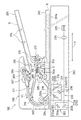
3 and 4 are diagrams illustrating a schematic configuration of a
図3及び図4に示すように、本実施形態の光源ユニット210は、発光素子アレイユニット215と、この発光素子アレイユニット215が設けられるミラーベースユニット216とを備えている。
As shown in FIGS. 3 and 4, the
発光素子アレイユニット215は、第1光源211aである複数の第1発光素子212a,…が設けられた第1光源基板213aと、第2光源211bである複数の第2発光素子212b,…が設けられた第2光源基板213bと、第1光源基板213a及び第2光源基板213bが設けられた基台214とを備えている。
The light emitting
第1光源基板213aと第2光源基板213bとは、原稿Gにおける主走査方向Xに延びた板状部材であって、主走査方向Xに直交する副走査方向Yに所定の間隔をあけて平行に配置されており、この状態で主走査方向Xの両端部が、基台214の主走査方向Xの両端部に形成された固定片214a,214bにビス等の固定部材SCにてそれぞれ固定されている。このように固定された第1光源基板213aと第2光源基板213bとの間は、原稿Gからの反射光を通過させるための主走査方向Xに沿って延びるスリットRとなっており、このスリットRは、後述する原稿読取位置である光照射領域L’の下方に位置している。
The first
ミラーベースユニット216には、第1ミラー230が設けられている。この第1ミラー230は、原稿Gの光照射面G’で反射した光を基台214に設けられたスリットRを介してミラーユニット203の第2ミラー203aに導くものであり、ミラーベースユニット216の主走査方向Xに沿った開口部216aに対向するように配置されている。
The
次に、上記構成の光源ユニット210において、第1光源211a及び第2光源211bについてさらに詳しく説明する。
Next, in the
第1光源211a及び第2光源211bの各発光素子212a,212bは、同じタイプのものであり、光量や発光の際の指向特性等は何れも実質的に同一のものである。
The
第1発光素子212a,…及び第2発光素子212b,…は、原稿Gにおける光照射領域L’に向けて光を照射するものであり、第1光源基板213a及び第2光源基板213b上にそれぞれ直線状に列を成して配置されている。すなわち、第1発光素子212a,…と第2発光素子212b,…とは、原稿Gにおける光照射面G’に沿って配置されており、原稿読取位置である原稿Gの光照射領域L’を基準にして、副走査方向Yの両側の対称位置にそれぞれ配置されている。また、第1発光素子212a,…と第2発光素子212b,…とは、各光軸Lが光照射領域L’の主走査方向Xに対して直角になるように配置されている。すなわち、本実施形態では、複数の第1発光素子212a,…で構成される第1発光素子列と複数の第2発光素子212b,…で構成される第2発光素子列との2列に配置されている。
The first
本実施形態においては、第1発光素子212a,…及び第2発光素子212b,…は、何れも発光ダイオード(LED素子)を用いている。従って、第1発光素子212a,…及び第2発光素子212b,…は、所定方向に強い指向特性を有している。各発光素子212a,…,212b,…から出射される光のうち光束が最も強くなる方向を光軸Lとしている。
In the present embodiment, the first
また、本実施形態においては、複数の第1発光素子212a,…及び複数の第2発光素子212b,…の各ピッチは、同一の発光素子ピッチP(素子中心間の主走査方向Xにおける距離が同一)となっている。さらに、前記第1発光素子列及び前記第2発光素子列において、第1発光素子212a,…及び第2発光素子212b,…は、ピッチ位置が副走査方向Yで揃うように(同一ピッチ位置構成で)配列されている。
Further, in the present embodiment, each of the plurality of first
さらに、本実施形態においては、第1発光素子212a,…及び第2発光素子212b,…は、第1光源基板213a及び第2光源基板213bの各基板面Fに対して光軸Lが平行になるように光を射出するサイド発光を行う発光面E1を有している。そのため、各光軸Lが光照射領域L’へ向くように、第1光源基板213a及び第2光源基板213bは原稿G側とは反対側が開いた「ハの字」型に傾斜配置されている。なお、光照射領域L’は、第1発光素子212a,…及び第2発光素子212b,…の中間に位置している。
Further, in the present embodiment, the first
図5に示す構成では、複数の発光素子212a,…及び複数の発光素子212b,…を、光照射領域L’を基準にして、副走査方向Yの両側に配置しているが、片側のみに配置してもよい。
5, the plurality of
図6は、複数の発光素子212,…が光照射領域L’を基準にして、副走査方向Yの片側のみに配置されている例を示す概略側面図である。
FIG. 6 is a schematic side view showing an example in which the plurality of
図6に示す複数の発光素子212,…は、光照射領域L’を基準に副走査方向Yの片側に配置された光源基板213に搭載されており、基板面Fに対して光軸Lが平行になるように光を射出するサイド発光を行う発光面E1を有している。具体的には、光源基板213は、光軸Lの方向が光照射領域L’へ向くように傾斜配置されている。
6 are mounted on a
また、複数の発光素子212,…が両側に配置されているか或いは片側のみに配置されているかに係わらず、搭載される光源基板213の基板面Fに対して光軸Lが垂直になるように光を射出する頂面発光を行ってもよい。
Further, the optical axis L is perpendicular to the substrate surface F of the
図7は、頂面発光を行う発光面E2を有する複数の発光素子212,…の一例を示す概略側面図であって、(a)は、両側に配置された第1発光素子212a,…及び第2発光素子212b,…が頂面発光を行う一例を示しており、(b)は、片側のみに配置された発光素子212,…が頂面発光を行う一例を示している。
FIG. 7 is a schematic side view showing an example of a plurality of
図7(a)に示すように、第1発光素子212a,…及び第2発光素子212b,…が頂面発光を行う発光面E2を有する場合には、光軸Lの方向が光照射領域L’へ向くように原稿側が開いた逆「ハの字」形に第1光源基板213a及び第2光源基板213bを配置する。なお、光照射領域L’は、第1光源基板213a及び第2光源基板213bの中間に位置している。
As shown in FIG. 7A, when the first
また、図7(b)に示すように、発光素子212,…が片側のみに配置されている場合には、光軸Lの方向が光照射領域L’へ向くように光源基板213を傾斜配置することができる。
7B, when the
このように、発光素子は図5〜図7に示す配置構成とすることができるが、何れにしても、発光素子がサイド発光と頂面発光とのうち何れかの発光を行う発光面E1,E2を有していると、光源ユニット210内の構成部品の配置構成に応じて、サイド発光を行う発光面E1を有する発光素子と頂面発光を行う発光面E2を有する発光素子との使い分けを行うことで、光源ユニット210内の空いたスペースを有効に利用することができる。
As described above, the light emitting element can be arranged as shown in FIGS. 5 to 7, but in any case, the light emitting surface E <b> 1, on which the light emitting element emits one of side light emission and top surface light emission. When E2 is provided, the light emitting element having the light emitting surface E1 that emits side light and the light emitting element having the light emitting surface E2 that emits top light are selectively used according to the arrangement of the components in the
(上記第1及び第2発光素子の配列に伴う原稿面での照射ムラの説明)
図8は、発光素子の配列に伴う原稿面での照射ムラを説明する図である。ここでは、図5に示す配列を例に挙げて照射ムラを説明する。
(Explanation of Irradiation Unevenness on Document Surface Associated with Arrangement of First and Second Light Emitting Elements)
FIG. 8 is a diagram for explaining irradiation unevenness on the document surface due to the arrangement of the light emitting elements. Here, irradiation unevenness will be described by taking the arrangement shown in FIG. 5 as an example.
画像読み取りでは、均一な光で原稿Gを照射することが望ましいが、発光素子(LED素子)の光は点光源であり指向性を有しているため、図8に示すように、第1発光素子212a及び第2発光素子212bの直上部分は明るく、隣接する発光素子との中間部分では光量が落ちて暗くなる。そのため、原稿面照度は、原稿Gの光照射面G’の主走査方向Xに沿ってサインカーブが連続するような波形の曲線を描くように変化し、照度の中間レベルN1に対し、区間T1では中間レベルN1より照度が高く、区間T2では中間レベルN1より照度が低くなっている。なお、区間T1+区間T2が照度周期Tであり、発光素子ピッチPに等しくなっている。
In the image reading, it is desirable to irradiate the original G with uniform light. However, since the light from the light emitting element (LED element) is a point light source and has directivity, the first light emission is performed as shown in FIG. The portion immediately above the
(レンズのシェーディング特性の説明)
図9は、レンズのシェーディング特性を示す曲線図である。縮小光学系に使用されるレンズは、その特性として、レンズ中央部に対応する区間T11を通る光量が大きく、この区間T11からレンズ端部までの間の区間T12では、レンズ中央部からレンズ端部に向かうほど光量が小さくなる全体として山形のカーブを描くことになる。
(Explanation of lens shading characteristics)
FIG. 9 is a curve diagram showing the shading characteristics of the lens. The lens used in the reduction optical system has a large amount of light passing through the section T11 corresponding to the center of the lens as a characteristic. In the section T12 from the section T11 to the lens end, the lens center to the lens end. As a result, the amount of light decreases as it goes to the center, and an overall curve is drawn.
(画像読取素子に入射される照度ムラとレンズのシェーディング特性がのった光信号の光量変化の説明)
図10は、照度ムラとレンズのシェーディング特性がのった光信号の画像読取素子での光量の変化を示す説明図である。
(Explanation of change in light quantity of optical signal with uneven illumination and lens shading characteristics incident on image reading element)
FIG. 10 is an explanatory diagram showing a change in the amount of light in the image reading element of an optical signal having illuminance unevenness and lens shading characteristics.
発光素子(第1発光素子212a及び第2発光素子212b)による照度ムラと、レンズ(集光レンズ204)によるシェーディング特性の影響を受ける結果、光源からレンズを通って画像読取素子である撮像素子に入射する光量は、原稿Gが均一な白色の場合でも、図10(b)に示すように、中央部の光量が大きく(レンズによる影響)、かつ、発光素子の間隔に応じたムラ(ヒゲ状のムラ)を持った光量となる。そこで、発光素子の特性に応じた拡散板を第1光源211a及び第2光源211bと原稿Gとの間に配置することで、図10(c)に示すように照度ムラが解消された光量とすることができ、さらに、レンズの特性に応じた拡散板を第1光源211a及び第2光源211bと原稿Gとの間(若しくは第1光源211a及び第2光源211bとレンズとの間)に配置することで、図10(d)に示すように、原稿Gの主走査方向Xの全幅においてほぼ均一な光量にすることができる。
As a result of being affected by uneven illuminance due to the light emitting elements (first
従って、本発明では、上記構成の光学ユニット210において、第1光源211a及び第2光源211bと原稿Gとの間(若しくは第1光源211a及び第2光源211bとレンズとの間)に、レンズの特性に応じた拡散板と、発光素子の特性に応じた拡散板とを配置することで、レンズ特性による読取画像の劣化を防止し、併せて発光素子による照度ムラを解消するものである。以下、拡散板自体の構成及び拡散板の配置構成について具体的に説明する。まず、拡散板の配置構成の具体例について説明する。
Therefore, according to the present invention, in the
(拡散板の配置構成の具体例1)
図11は、本実施形態における拡散板の配置構成の具体例1を示す説明図である。
(Specific example 1 of the arrangement configuration of the diffusion plate)
FIG. 11 is an explanatory view showing a specific example 1 of the arrangement configuration of the diffusion plates in the present embodiment.
本具体例1の拡散板は、縮小光学系のレンズ特性に応じたパターンと、発光素子の照度ムラに応じたパターンの両方のパターンが印刷された1枚の拡散板51で構成されている。この場合、拡散板51は、複数の第1発光素子212a,…及び複数の第2発光素子212b,…と原稿Gとの間の光路上に(すなわち、光路を横切るように)それぞれ配置されている。
The diffusion plate of this specific example 1 is composed of a
このように、発光素子(第1発光素子212a及び第1発光素子212a)による照度ムラに対応したパターンが印刷された拡散板51を配置することで、ほぼ均一な照度レベルの光を原稿Gに照射することができる。また、縮小光学系のレンズ特性に対応したパターンを印刷した拡散板51を配置することで、原稿Gからの反射光が、集光レンズ204を通ったときには主走査方向に対してほぼ均一な照度レベルの出力となるように補正して、撮像素子205に導くことができる。これにより、撮像素子205の出力を補正する必要が無くなる。すなわち、集光レンズ204の中央部と端部とに対応する位置から出てくる出力の照度レベルを同等にすることができる。
As described above, by arranging the
(拡散板の配置構成の具体例2)
図12は、本実施形態における拡散板の配置構成の具体例2を示す説明図である。
(Specific example 2 of arrangement configuration of diffusion plate)
FIG. 12 is an explanatory diagram showing a specific example 2 of the arrangement configuration of the diffusion plates in the present embodiment.
本具体例2の拡散板は、発光素子の照度ムラに応じたパターンが印刷された第1拡散板52と、縮小光学系のレンズ特性に応じたパターンが印刷された第2拡散板53の2枚の拡散板で構成されている。この場合、本具体例2では、複数の第1発光素子212a,…及び複数の第2発光素子212b,…と原稿Gとの間の光路上(すなわち、光路を横切るように)に、第1拡散板52と第2拡散板53の両方がそれぞれ配置されている。すなわち、複数の第1発光素子212a,…及び複数の第2発光素子212b,…の前方に第1拡散板52がそれぞれ配置され、これら第1拡散板52の前方に第2拡散板53がそれぞれ配置されている。
The diffusion plate of this specific example 2 includes a
このように、発光素子(第1発光素子212a及び第1発光素子212a)による照度ムラに対応したパターンが印刷された第1拡散板52を配置することで、ほぼ均一な照度の光を原稿Gに照射することができる。また、縮小光学系のレンズ特性に対応したパターンを印刷した第2拡散板53を配置することで、原稿Gからの反射光を、集光レンズ204を通ったときには主走査方向に対してほぼ均一な照度レベルの出力となるように補正して、撮像素子205に導くことができる。これにより、撮像素子205の出力を補正する必要が無くなる。すなわち、集光レンズ204の中央部と端部とに対応する位置から出てくる出力の照度レベルを同等にすることができる。
As described above, by arranging the
(拡散板の配置構成の具体例3)
図13は、本実施形態における拡散板の配置構成の具体例3を示す説明図であり、上記具体例2の変形例である。
(Specific example 3 of the arrangement configuration of the diffusion plate)
FIG. 13 is an explanatory diagram showing a specific example 3 of the arrangement configuration of the diffusion plates in the present embodiment, and is a modification of the specific example 2. In FIG.
すなわち、本具体例3の拡散板も、発光素子の照度ムラに応じたパターンが印刷された第1拡散板52と、縮小光学系のレンズ特性に応じたパターンが印刷された第2拡散板53の2枚の拡散板で構成されている。ただし、本具体例3では、複数の第1発光素子212a,…及び複数の第2発光素子212b,…と原稿Gとの間の光路上に(すなわち、光路を横切るように)第1拡散板52がそれぞれ配置され、レンズ特性に応じたパターンが印刷された第2拡散板53は、原稿Gからの反射光の光路上に(すなわち、光路を横切るように)1個配置されている。より具体的には、第2拡散板53は、原稿Gと第1ミラー230との間の光路上に(すなわち、光路を横切るように)配置されている。
That is, the diffusion plate of this specific example 3 also includes the
すなわち、本具体例3は、複数の第1発光素子212a,…側の第2拡散板としての機能と、複数の第2発光素子212b,…側の第2拡散板としての機能の両方の機能を1個の第2拡散板53で担う構成となっている。このように、第2拡散板53を共通使用することで、上記具体例2に比べて光路周辺に配置する部品点数を減らすことが可能となる。
That is, this specific example 3 has both a function as a second diffusion plate on the plurality of first
次に、拡散板に印刷される不透光な印刷パターンの実施例について説明する。なお、印刷パターンの説明では、第1発光素子212a,…側に配置される拡散板も第2発光素子212b,…に配置される拡散版も同じであるので、以下の説明では第1発光素子212aと第2発光素子212bとを区別することなく、単に発光素子212として説明する。また、これらが設けられる第1光源基板213aと第2光源基板213bも区別することなく、単に光源基板213として説明する。
Next, an example of an opaque print pattern printed on the diffusion plate will be described. In the description of the print pattern, the diffusion plate disposed on the first
(印刷パターンの実施例1)
本実施例1は、拡散板が1枚の場合の印刷パターンの実施例である。
(Example 1 of printing pattern)
The first embodiment is an example of a printing pattern when there is one diffusion plate.
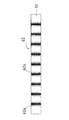
図14は、拡散板51に印刷された実施例1の印刷パターンを示す説明図であり、(a)は拡散板51の表面図、(b)は拡散板51の側面図、(c)は拡散板51の裏面図、(d)は発光素子212(第1発光素子212a及び第2発光素子212bに共通)が設けられた光源基板213(第1光源基板213a及び第2光源基板213bに共通)の側面図であり、(d)に示す各発光素子212の配置位置と(c)に示す拡散板51の裏面側の印刷パターンの印刷位置とが対応している。
14A and 14B are explanatory views showing a printing pattern of Example 1 printed on the
本実施例1の拡散板51は、光源基板213の主走査方向Xの長さと同等な長さを有する長尺形状の透明基材55からなり、この透明基板55の表面側に、縮小光学系のレンズ特性に対応した不透光な印刷パターン61が印刷され、裏面側に、発光素子212による照度ムラに対応した不透光な印刷パターン62が印刷された実施例である。透明基材55としては、アクリル樹脂やPC(ポリカーボネート)、透明シリコン、透明ガスラなどの部材を用いることができる。このように不透光なインクを用いてパターンを印刷することで、手軽で安価に拡散板を作成することができる。
The
透明基板55の裏面側に印刷された印刷パターン62は、本実施形態では所定幅T1の縦縞模様状の1組の印刷パターン群62aが、主走査方向Xに沿って所定の間隔T2を存して連続的に形成されたものである。1組の印刷パターン群62aは、1個の発光素子212に対応している。また、所定幅T1及び所定の間隔T2は、図8に示した区間T1,T2に対応している。
The
すなわち、1組の印刷パターン群62aについて見ると、発光素子212の直上に対応する部分(中央部分)の縞の幅が太く、この中央部分から左右(主走査方向X)に離れるに従って縞の幅が徐々に細くなるように(逆に言えば、縞と縞の間の白い部分の幅が徐々に広くなるように)印刷されている。縞の数は、図14に示した例では、中央部の太い縦縞を挟んで左右に2本、計5本印刷しているが、このような5本に限定されるものではなく、発光素子212の指向性や照度ムラの特性、さらには発光素子ピッチP等を考慮してより細かく本数や間隔を設定すればよい。
That is, when viewing the set of
一方、透明基板55の表面側に印刷された印刷パターン61は、本実施形態ではレンズ中央部の所定幅に対応する部分T11のインク濃度を濃く印刷し、レンズ中央部の所定幅に対応する部分T11から左右に連続する所定幅の部分T12,T12については、レンズ中央部の所定幅に対応する部分T11から離れるに従ってインク濃度が徐々に薄くなるように印刷されたものである。なお、レンズ中央部の所定幅に対応する部分T11及びレンズ中央部の所定幅に対応する部分T11から左右に連続する所定幅の部分T12は、図9に示した区間T11,T12にそれぞれ対応している。
On the other hand, the
図15は、上記のように構成した拡散板51を用いた場合の、光量変化の様子を示す説明図である。
FIG. 15 is an explanatory diagram showing a change in the amount of light when the diffusing
複数の発光素子212,…から照射された光は、各発光素子212の有する照射ムラの関係で、図中の符号71で示すように、主走査方向Xに沿って連続したサインカーブを描くような山形の波形として出射される。このような波形の光が拡散板51の裏面側に設けられた印刷パターン62を通過すると、その透過光は、図中の符号72で示すように、山部分がほぼ平坦に均され、主走査方向Xに沿ってほぼ均等な出射光量の光となる。そして、この光が拡散板51の表面側に設けられた印刷パターン61を通過すると、その透過光は、図中の符号73で示すように、主走査方向Xの中央部が湾曲状に凹んだ逆山形状の光となって出射されることになる。この符号73で示す逆山形状の波形は、図9に示したレンズのシェーディング特性を示す曲線と逆形状の曲線となっている。従って、このように補正された光が原稿Gの光照射面G’で反射され、その反射光が各ミラーで反射され、集光レンズ204を通ったときには主走査方向Xに対してほぼ均一な出射光量(照度レベル)の出力となるように補正されて、撮像素子205に導かれることになる。
The light emitted from the plurality of
図16は、発光素子の照度ムラに対応した印刷パターン62の他の例を示しており、発光素子212の直上に対応する部分T21のインク濃度が濃く、この直上に対応する部分T21から左右(主走査方向X)に離れるに従って徐々にインク濃度が薄くなるように印刷された構成としてもよい。また、印刷パターン62のさらに他の例として、図示は省略しているが、濃度の薄いインクを複数回重ねて印刷した構成としてもよい。すなわち、発光素子の直上に対応する部分の印刷回数が多く、直上に対応する部分から左右(主走査方向X)に離れるに従って徐々に印刷回数が少なくなるように印刷された構成としてもよい。
FIG. 16 shows another example of the
一方、レンズ特性に対応した印刷パターン61の他の例としては、レンズ中央部の所定幅に対応する部分T11のインクドットを高密度とし、レンズ中央部の所定幅に対応する部分T11から左右に連続する所定幅の部分T12,T12については、レンズ中央部の所定幅に対応する部分T11から離れるに従ってインクドットの密度が徐々に低密度となるように印刷した構成としてもよい。
On the other hand, as another example of the
なお、上記実施例1では、透明基板55の表面側に、縮小光学系のレンズ特性に対応した不透光な印刷パターン61を印刷し、裏面側に、発光素子212による照度ムラに対応した不透光な印刷パターン62を印刷しているが、透明基板55の表面側に、発光素子212による照度ムラに対応した不透光な印刷パターン62を印刷し、裏面側に、縮小光学系のレンズ特性に対応した不透光な印刷パターン61を印刷してもよい。
In Example 1 described above, a
本発明は、このような構成の照明装置を画像読取装置に備えることで、原稿Gに対して主走査方向Xに照度ムラの無い(若しくは少ない)ほぼ均一な照度レベルの光を照射し、原稿Gの反射光に対してシェーディング補正を行って画像読取素子である撮像素子205に導くことができる画像読取装置を実現することができる。また、この画像読取装置を画像形成装置に搭載することで、原稿の読み取り品質に優れた画像形成装置を実現することができる。
According to the present invention, the illumination device having such a configuration is provided in the image reading apparatus, so that the original G is irradiated with light having a substantially uniform illuminance level in the main scanning direction X with no (or small) illuminance unevenness. It is possible to realize an image reading apparatus capable of performing shading correction on the reflected light of G and guiding the reflected light to the
(印刷パターンの実施例2)
本実施例2は、拡散板が1枚の場合の印刷パターンの実施例である。
(Example 2 of printing pattern)
The second embodiment is an example of a printing pattern in the case where there is one diffusion plate.
図17は、拡散板51に印刷された実施例2の印刷パターンを示す説明図であり、(a)は拡散板51の表面図、(b)は拡散板51の側面図、(c)は拡散板51の裏面図、(d)は発光素子212が設けられた光源基板213の側面図であり、(d)に示す各発光素子212の配置位置と(c)に示す拡散板51の裏面側の印刷パターンの印刷位置とが対応している。
FIG. 17 is an explanatory view showing a printing pattern of Example 2 printed on the
本実施例2の拡散板51は、光源基板213の主走査方向Xの長さと同等な長さを有する長尺形状の透明基材55からなり、この透明基板55の一方の面(この例では裏面)側に、縮小光学系のレンズ特性に対応した不透光な印刷パターン61と、発光素子212による照度ムラに対応した不透光な印刷パターン62の両方を合わせて(重ねて)印刷した実施例である。なお、印刷パターン61,62については、重ねて印刷する以外は、上記実施例1の印刷パターンと同じであるので、ここでは印刷パターンについての説明を省略する。また、印刷パターン61,62の印刷面については、透明基板55の裏面側ではなく表面側に印刷してもよい。
The diffusing
本実施例2によれば、両印刷パターン61,62を透明基板55の片面に印刷しているので、印刷パターン61,62の印刷工程が上記実施例1の場合に比べて簡略化されることになる。すなわち、透明基板55を表裏反転させる工程が不要となる。
According to the second embodiment, since both the
(印刷パターンの実施例3)
本実施例3は、拡散板が2枚の場合の印刷パターンの実施例である。
(Example 3 of printing pattern)
The third embodiment is an example of a printing pattern when there are two diffusion plates.
図18は、拡散板に印刷された実施例3の印刷パターンを示す説明図であり、(a)は第2拡散板53の3面図(上から表面図、側面図、裏面図)、(b)は第1拡散板52の3面図(上から表面図、側面図、裏面図)、(c)は発光素子212が設けられた光源基板213の側面図であり、(c)に示す各発光素子212の配置位置と(b)に示す第1拡散板52の裏面側の印刷パターンの印刷位置とが対応している。
FIG. 18 is an explanatory view showing a printing pattern of Example 3 printed on the diffusion plate, (a) is a three-side view (front view, side view, back view) of the
本実施例3では、第1拡散板52及び第2拡散板52は、光源基板213の主走査方向Xの長さと同等な長さを有する長尺形状の透明基材55からなり、この透明基板55の一方の面に、縮小光学系のレンズ特性に対応した不透光な印刷パターン61、又は、発光素子212による照度ムラに対応した不透光な印刷パターン62が印刷された実施例である。
In the third embodiment, the
具体的に説明すると、第1拡散板52の裏面側に、発光素子212による照度ムラに対応した不透光な印刷パターン62が印刷され、第2拡散板53の裏面側に、縮小光学系のレンズ特性に対応した不透光な印刷パターン61が印刷されている。ただし、第1拡散板52の表面側に、発光素子212による照度ムラに対応した不透光な印刷パターン62が印刷され、第2拡散板53の表面側に、縮小光学系のレンズ特性に対応した不透光な印刷パターン61が印刷されていてもよい。すなわち、各印刷パターン61,62の印刷面は、透明基板55の表裏どちらでもよい。
More specifically, an
なお、印刷パターン61,62については、上記実施例1の印刷パターンと同じであるので、ここでは印刷パターンについての説明を省略する。
Since the
本発明の照明装置を画像読取装置に搭載した場合、画像読取装置では、光照射側の特性(複数の発光素子からなるLEDアレイの照度ムラ)に対応したパターンと、光受光側の特性(縮小光学系のレンズ、及びCCD等の画像読取素子によるシェーディング特性)に対応したパターンとを、上記実施例3のように分離して(個別に)作成することで、印刷するパターンの数を減らすことができる。 When the illumination device of the present invention is mounted on an image reading device, the image reading device has a pattern corresponding to the characteristics on the light irradiation side (illuminance unevenness of the LED array composed of a plurality of light emitting elements) and the characteristics on the light receiving side (reduction). The pattern corresponding to the lens of the optical system and the shading characteristic by the image reading element such as a CCD) is created separately (individually) as in the third embodiment, thereby reducing the number of patterns to be printed. Can do.
例えば、同一読み取りサイズの画像読取装置が複数機種あった場合を想定し、画像読取装置に使用されるLEDアレイが3種、縮小光学系のレンズが3種であったと仮定すると、これらの種類に応じたパターンを拡散板の表裏両面又は片面に印刷する場合(上記実施例1,2の場合)、印刷パターンとしては3×3の9種(全ての組み合わせ分)が必要となりる。一方、これらのパターンを拡散板の一つの面に個別に印刷する場合(上記実施例3の場合)、印刷パターンとしては3+3の6種で対応することが可能となる。 For example, assuming that there are a plurality of types of image reading apparatuses having the same reading size, and assuming that there are three types of LED arrays used in the image reading apparatus and three types of lenses of the reduction optical system, these types are used. When the corresponding pattern is printed on both the front and back sides or one side of the diffusion plate (in the case of Examples 1 and 2 above), nine types of 3 × 3 (all combinations) are required as print patterns. On the other hand, when these patterns are individually printed on one surface of the diffusion plate (in the case of the third embodiment), it is possible to deal with 6 types of 3 + 3 print patterns.
具体的に説明すると、LEDアレイとして、発光素子ピッチ(配置ピッチ)や照度ムラの異なるA,B,Cの3種があり、集束レンズとして、端部と中央部の照度差に違いのあるa,b,cの3種があったとすると、それぞれの組み合わせのパターンを1枚の拡散板の表裏両面又は片面に印刷する場合には、Aa,Ab,Ac,Ba,Bb,Bc,Ca,Cb,Ccの9種類の組み合わせパターンが印刷された9枚の拡散板が必要となる。 More specifically, there are three types of LED arrays, A, B, and C, which have different light emitting element pitches (arrangement pitches) and uneven illuminances, and the focusing lens has a difference in illuminance difference between the end and the central part. , B, and c, when a pattern of each combination is printed on both the front and back sides or one side of one diffusion plate, Aa, Ab, Ac, Ba, Bb, Bc, Ca, Cb , Cc, nine diffusion plates printed with nine kinds of combination patterns are required.
一方、1枚の拡散板の一面に各パターンを個別に印刷する場合は、表面用のA,B,Cと、裏面用のa,b,cの6種類のパターンが個別に印刷された6枚の拡散板で全ての組み合わせの画像読取装置を実現することが可能となる。 On the other hand, when each pattern is individually printed on one surface of one diffusion plate, six types of patterns A, B, and C for the front surface and a, b, and c for the back surface are individually printed 6 All combinations of image reading apparatuses can be realized with a single diffusion plate.
本発明は、一次元的に配列されたLED素子(LEDアレイ)を照明装置とした原稿等の画像読取装置及びそれを備えた画像形成装置の分野に利用可能なものである。 INDUSTRIAL APPLICABILITY The present invention can be used in the field of an image reading apparatus such as an original using an LED device (LED array) arranged one-dimensionally as an illuminating device, and an image forming apparatus including the image reading apparatus.
51 拡散板
52 第1拡散板
53 第2拡散板
61,62 印刷パターン
62a 1組の印刷パターン群
100 画像読取装置
200 原稿読取部
201a 原稿台ガラス
201b 原稿読取ガラス
202 枠体
203 ミラーユニット
203a 第2ミラー
203b 第3ミラー
204 集光レンズ
205 撮像素子(画像読取素子)
210 光源ユニット(照明装置の一例)
211 光源
211a 第1光源
211b 第2光源
212 発光素子(LED素子)
212a 第1発光素子
212b 第2発光素子
213 光源基板
213a 第1光源基板
213b 第2光源基板
214 基台
214a,214b 固定片
215 発光素子アレイユニット
216 ミラーベースユニット
216a 開口部
230 第1ミラー
D 画像形成装置
E1 サイド発光を行う発光面
E2 頂面発光を行う発光面
G 原稿
G’ 原稿の光照射面
R スリット
SC 固定部材
L 光軸
L’ 光照射領域
P 発光素子ピッチ
T 照度周期
T1 所定幅(1組の印刷パターン群の幅)(中間レベルN1より照度が高い区間)
T2 所定の間隔(中間レベルN1より照度が低い区間)
T11 レンズ中央部に対応する区間(レンズ中央部の所定幅に対応する部分)
T12 区間T11からレンズ端部までの間の区間(T11から左右に連続する所定幅の部分)
X 主走査方向
Y 副走査方向(原稿搬送方向)
51
210 Light source unit (an example of a lighting device)
212a First light emitting
T2 Predetermined interval (section where the illuminance is lower than the intermediate level N1)
T11 Section corresponding to the center of the lens (part corresponding to a predetermined width of the center of the lens)
T12 A section from the section T11 to the end of the lens (a portion having a predetermined width that continues from T11 to the left and right)
X Main scanning direction Y Sub-scanning direction (original transport direction)
Claims (15)
前記発光素子の前方に光学系レンズのレンズ特性に対応した拡散板が配置されていることを特徴とする照明装置。 In an illumination device in which a plurality of light emitting elements are arranged in a row,
An illuminating device characterized in that a diffuser plate corresponding to the lens characteristics of an optical lens is disposed in front of the light emitting element.
前記レンズ特性が撮像素子に集光する光学系に使用されるレンズの特性であることを特徴とする請求項1に記載の照明装置。 The lighting device according to claim 1.
The illumination device according to claim 1, wherein the lens characteristic is a characteristic of a lens used in an optical system that focuses light on an image sensor.
前記発光素子の前方に当該発光素子による照度ムラに対応した拡散板が配置されていることを特徴とする照明装置。 The lighting device according to claim 1 or 2,
An illuminating device, wherein a diffusion plate corresponding to uneven illuminance due to the light emitting element is disposed in front of the light emitting element.
前記拡散板は、透明基材の上に不透光な印刷パターンが形成されていることを特徴とする照明装置。 In the illuminating device of any one of Claim 1- Claim 3,
The diffusing plate has an opaque printing pattern formed on a transparent substrate.
前記拡散板は、透明基材の一方の面にレンズ特性に対応した不透光な印刷パターンが形成され、他方の面に前記発光素子の照度ムラに対応した不透光な印刷パターンが形成されていることを特徴とする照明装置。 In the lighting device according to claim 4,
The diffusing plate has an opaque printing pattern corresponding to lens characteristics formed on one surface of a transparent substrate, and an opaque transmitting pattern corresponding to illuminance unevenness of the light emitting element is formed on the other surface. A lighting device characterized by that.
前記拡散板は、透明基材の一方の面に、レンズ特性に対応した不透光な印刷パターンと前記発光素子の照度ムラに対応した不透光な印刷パターンとが合わせて形成されていることを特徴とする照明装置。 In the lighting device according to claim 4,
The diffusion plate is formed on one surface of a transparent base material with an opaque print pattern corresponding to lens characteristics and an opaque print pattern corresponding to illuminance unevenness of the light emitting element. A lighting device characterized by the above.
前記拡散板は、前記発光素子と原稿との間の光路に配置されることを特徴とする照明装置。 In the illuminating device of any one of Claim 1- Claim 6,
The illuminating device, wherein the diffusion plate is disposed in an optical path between the light emitting element and the original.
発光素子の照度ムラに対応した拡散板は前記発光素子と原稿との間の光路に配置され、前記レンズ特性に対応した拡散板は原稿からの反射光の光路に配置されていることを特徴とする照明装置。 In the illuminating device of Claim 3 or Claim 4,
A diffusion plate corresponding to uneven illuminance of the light emitting element is disposed in an optical path between the light emitting element and the original, and a diffusion plate corresponding to the lens characteristic is disposed in an optical path of reflected light from the original. Lighting device.
発光素子の照度ムラに対応した前記印刷パターンは、縞模様状のパターンであり、前記発光素子の直上に対応する部分の縞が太く、前記直上に対応する部分から離れるに従って縞が徐々に細くなるように印刷されていることを特徴とする照明装置。 In the illuminating device of any one of Claim 4 to Claim 8,
The printed pattern corresponding to the illuminance unevenness of the light emitting element is a striped pattern. The lighting device is characterized by being printed as follows.
発光素子の照度ムラに対応した前記印刷パターンは、前記発光素子の直上に対応する部分のインク濃度が濃く、前記直上に対応する部分から離れるに従ってインク濃度が徐々に薄くなるように印刷されていることを特徴とする照明装置。 In the illuminating device of any one of Claim 4 to Claim 8,
The printed pattern corresponding to the illuminance unevenness of the light emitting element is printed such that the ink density of the portion corresponding directly above the light emitting element is high, and the ink concentration gradually decreases as the distance from the portion corresponding to the light emitting element increases. A lighting device characterized by that.
発光素子の照度ムラに対応した前記印刷パターンは、濃度の薄いインクが複数回重ねて印刷されたものであり、前記発光素子の直上に対応する部分の印刷回数が多く、前記直上に対応する部分から離れるに従って徐々に印刷回数が少なくなるように印刷されていることを特徴とする照明装置。 In the illuminating device of any one of Claim 4 to Claim 8,
The printed pattern corresponding to the illuminance unevenness of the light emitting element is printed by overlapping a low density ink a plurality of times, and the number of times of printing of the part corresponding directly above the light emitting element is large, and the part corresponding to the immediately above The lighting device is characterized in that printing is performed so that the number of times of printing gradually decreases as the distance from the device increases.
レンズ特性に対応した前記印刷パターンは、レンズ中央部に対応する部分のインク濃度が濃く、前記レンズ中央部に対応する部分から離れるに従ってインク濃度が徐々に薄くなるように印刷されていることを特徴とする照明装置。 In the illuminating device of any one of Claim 4 to Claim 11,
The printing pattern corresponding to the lens characteristics is printed such that the ink density in the portion corresponding to the lens central portion is high and the ink concentration gradually decreases as the distance from the portion corresponding to the lens central portion increases. A lighting device.
レンズ特性に対応した前記印刷パターンは、レンズ中央部に対応する部分のインクドットが高密度、前記レンズ中央部に対応する部分から離れるに従ってインクドットが徐々に低密度となるように印刷されていることを特徴とする照明装置。 In the illuminating device of any one of Claim 4 to Claim 11,
The print pattern corresponding to the lens characteristics is printed such that the ink dots in the portion corresponding to the center portion of the lens have a high density, and the ink dots gradually decrease in density as the distance from the portion corresponding to the center portion of the lens increases. A lighting device characterized by that.
Priority Applications (1)
| Application Number | Priority Date | Filing Date | Title |
|---|---|---|---|
| JP2009117774A JP2010268221A (en) | 2009-05-14 | 2009-05-14 | Lighting device, image reader and image forming apparatus |
Applications Claiming Priority (1)
| Application Number | Priority Date | Filing Date | Title |
|---|---|---|---|
| JP2009117774A JP2010268221A (en) | 2009-05-14 | 2009-05-14 | Lighting device, image reader and image forming apparatus |
Publications (1)
| Publication Number | Publication Date |
|---|---|
| JP2010268221A true JP2010268221A (en) | 2010-11-25 |
Family
ID=43364840
Family Applications (1)
| Application Number | Title | Priority Date | Filing Date |
|---|---|---|---|
| JP2009117774A Pending JP2010268221A (en) | 2009-05-14 | 2009-05-14 | Lighting device, image reader and image forming apparatus |
Country Status (1)
| Country | Link |
|---|---|
| JP (1) | JP2010268221A (en) |
Cited By (2)
| Publication number | Priority date | Publication date | Assignee | Title |
|---|---|---|---|---|
| JP2019216336A (en) * | 2018-06-12 | 2019-12-19 | 京セラドキュメントソリューションズ株式会社 | Sensor unit and image forming apparatus including the same |
| JP2019216337A (en) * | 2018-06-12 | 2019-12-19 | 京セラドキュメントソリューションズ株式会社 | Sensor unit and image forming apparatus including the same |
Citations (8)
| Publication number | Priority date | Publication date | Assignee | Title |
|---|---|---|---|---|
| JPS62126856U (en) * | 1986-02-04 | 1987-08-12 | ||
| JPH03227167A (en) * | 1990-01-31 | 1991-10-08 | Rohm Co Ltd | Image sensor |
| JPH0429379A (en) * | 1990-05-24 | 1992-01-31 | Matsushita Electric Ind Co Ltd | Led array light source |
| JPH08111545A (en) * | 1994-08-19 | 1996-04-30 | Nec Corp | Led array light source |
| JP2003086849A (en) * | 2001-09-12 | 2003-03-20 | Matsushita Electric Ind Co Ltd | Surface emitting device |
| JP2005156600A (en) * | 2003-11-20 | 2005-06-16 | Ricoh Co Ltd | Lighting device, image reading apparatus and image forming apparatus |
| JP2006229587A (en) * | 2005-02-17 | 2006-08-31 | Konica Minolta Photo Imaging Inc | Image reader |
| WO2008032588A1 (en) * | 2006-09-15 | 2008-03-20 | Oisllee Planning Co., Ltd | Document illuminating method, document illuminating device, and image reader |
-
2009
- 2009-05-14 JP JP2009117774A patent/JP2010268221A/en active Pending
Patent Citations (8)
| Publication number | Priority date | Publication date | Assignee | Title |
|---|---|---|---|---|
| JPS62126856U (en) * | 1986-02-04 | 1987-08-12 | ||
| JPH03227167A (en) * | 1990-01-31 | 1991-10-08 | Rohm Co Ltd | Image sensor |
| JPH0429379A (en) * | 1990-05-24 | 1992-01-31 | Matsushita Electric Ind Co Ltd | Led array light source |
| JPH08111545A (en) * | 1994-08-19 | 1996-04-30 | Nec Corp | Led array light source |
| JP2003086849A (en) * | 2001-09-12 | 2003-03-20 | Matsushita Electric Ind Co Ltd | Surface emitting device |
| JP2005156600A (en) * | 2003-11-20 | 2005-06-16 | Ricoh Co Ltd | Lighting device, image reading apparatus and image forming apparatus |
| JP2006229587A (en) * | 2005-02-17 | 2006-08-31 | Konica Minolta Photo Imaging Inc | Image reader |
| WO2008032588A1 (en) * | 2006-09-15 | 2008-03-20 | Oisllee Planning Co., Ltd | Document illuminating method, document illuminating device, and image reader |
Cited By (4)
| Publication number | Priority date | Publication date | Assignee | Title |
|---|---|---|---|---|
| JP2019216336A (en) * | 2018-06-12 | 2019-12-19 | 京セラドキュメントソリューションズ株式会社 | Sensor unit and image forming apparatus including the same |
| JP2019216337A (en) * | 2018-06-12 | 2019-12-19 | 京セラドキュメントソリューションズ株式会社 | Sensor unit and image forming apparatus including the same |
| JP7077803B2 (en) | 2018-06-12 | 2022-05-31 | 京セラドキュメントソリューションズ株式会社 | Sensor unit and image forming device equipped with it |
| JP7077804B2 (en) | 2018-06-12 | 2022-05-31 | 京セラドキュメントソリューションズ株式会社 | Sensor unit and image forming device equipped with it |
Similar Documents
| Publication | Publication Date | Title |
|---|---|---|
| US10412254B2 (en) | Illuminating device, image reading apparatus and image forming apparatus | |
| JP4757340B2 (en) | Illumination apparatus, image reading apparatus including the illumination apparatus, and image forming apparatus including the image reading apparatus | |
| JP2010183497A (en) | Lighting system, image reading device, and image formation device | |
| JP4717107B2 (en) | Illumination apparatus, image reading apparatus, and image forming apparatus | |
| JP4901886B2 (en) | Illumination apparatus, image reading apparatus, and image forming apparatus | |
| WO2010084679A1 (en) | Lighting device, image reader, and image forming device | |
| JP2010268221A (en) | Lighting device, image reader and image forming apparatus | |
| JP2012118190A (en) | Image reading device and image formation device | |
| JP4920088B2 (en) | Illumination apparatus, image reading apparatus including the illumination apparatus, and image forming apparatus including the image reading apparatus | |
| US8385781B2 (en) | Image reading device and image forming apparatus including the same | |
| JP2010199639A (en) | Image reader and image forming apparatus | |
| JP5143101B2 (en) | Image reading apparatus and image forming apparatus | |
| JP5227833B2 (en) | Image reading apparatus and image forming apparatus | |
| JP5349344B2 (en) | Illumination apparatus, image reading apparatus including the illumination apparatus, and image forming apparatus including the image reading apparatus | |
| JP5328551B2 (en) | Illumination apparatus, image reading apparatus, image forming apparatus, and substrate | |
| JP2010210749A (en) | Image reader and image forming apparatus | |
| JP5530918B2 (en) | Image reading apparatus and image forming apparatus | |
| JP2011125052A (en) | Illuminance non-uniformity evaluating method and illuminance non-uniformity evaluating apparatus | |
| JP2010124118A (en) | Image reader and image forming apparatus | |
| JP2010212838A (en) | Image reader, and image forming device | |
| JP2012178227A (en) | Lighting system, image reading device and image forming apparatus | |
| JP2010109726A (en) | Luminaire, image reader, and image forming device | |
| JP2009171376A (en) | Illumination unit, image reader with the same, and image forming apparatus equipped with the unit | |
| JP2010197461A (en) | Image reader and image forming apparatus | |
| JP2011023968A (en) | Illuminating apparatus, image reading apparatus having the illuminating apparatus, and image forming apparatus having the image reading apparatus |
Legal Events
| Date | Code | Title | Description |
|---|---|---|---|
| A621 | Written request for application examination |
Free format text: JAPANESE INTERMEDIATE CODE: A621 Effective date: 20110824 |
|
| A977 | Report on retrieval |
Free format text: JAPANESE INTERMEDIATE CODE: A971007 Effective date: 20120423 |
|
| A131 | Notification of reasons for refusal |
Free format text: JAPANESE INTERMEDIATE CODE: A131 Effective date: 20120508 |
|
| A521 | Written amendment |
Free format text: JAPANESE INTERMEDIATE CODE: A523 Effective date: 20120626 |
|
| A131 | Notification of reasons for refusal |
Free format text: JAPANESE INTERMEDIATE CODE: A131 Effective date: 20130305 |
|
| A521 | Written amendment |
Free format text: JAPANESE INTERMEDIATE CODE: A523 Effective date: 20130418 |
|
| A02 | Decision of refusal |
Free format text: JAPANESE INTERMEDIATE CODE: A02 Effective date: 20131112 |