JP2010266191A - Medium temperature regulating system - Google Patents

Medium temperature regulating system Download PDF

Info

Publication number
JP2010266191A
JP2010266191A JP2010095331A JP2010095331A JP2010266191A JP 2010266191 A JP2010266191 A JP 2010266191A JP 2010095331 A JP2010095331 A JP 2010095331A JP 2010095331 A JP2010095331 A JP 2010095331A JP 2010266191 A JP2010266191 A JP 2010266191A
Authority
JP
Japan
Prior art keywords
air
heat pump
medium
heating
heat
Prior art date
Legal status (The legal status is an assumption and is not a legal conclusion. Google has not performed a legal analysis and makes no representation as to the accuracy of the status listed.)
Pending
Application number
JP2010095331A
Other languages
Japanese (ja)
Other versions
JP2010266191A5 (en
Inventor
Toshihiro Ichikawa
敏広 市川
Current Assignee (The listed assignees may be inaccurate. Google has not performed a legal analysis and makes no representation or warranty as to the accuracy of the list.)
Chubu Electric Power Co Inc
Original Assignee
Chubu Electric Power Co Inc
Priority date (The priority date is an assumption and is not a legal conclusion. Google has not performed a legal analysis and makes no representation as to the accuracy of the date listed.)
Filing date
Publication date
Application filed by Chubu Electric Power Co Inc filed Critical Chubu Electric Power Co Inc
Priority to JP2010095331A priority Critical patent/JP2010266191A/en
Publication of JP2010266191A publication Critical patent/JP2010266191A/en
Publication of JP2010266191A5 publication Critical patent/JP2010266191A5/ja
Pending legal-status Critical Current

Links

Images

Classifications

    • YGENERAL TAGGING OF NEW TECHNOLOGICAL DEVELOPMENTS; GENERAL TAGGING OF CROSS-SECTIONAL TECHNOLOGIES SPANNING OVER SEVERAL SECTIONS OF THE IPC; TECHNICAL SUBJECTS COVERED BY FORMER USPC CROSS-REFERENCE ART COLLECTIONS [XRACs] AND DIGESTS
    • Y02TECHNOLOGIES OR APPLICATIONS FOR MITIGATION OR ADAPTATION AGAINST CLIMATE CHANGE
    • Y02ATECHNOLOGIES FOR ADAPTATION TO CLIMATE CHANGE
    • Y02A30/00Adapting or protecting infrastructure or their operation
    • Y02A30/27Relating to heating, ventilation or air conditioning [HVAC] technologies
    • Y02A30/274Relating to heating, ventilation or air conditioning [HVAC] technologies using waste energy, e.g. from internal combustion engine
    • YGENERAL TAGGING OF NEW TECHNOLOGICAL DEVELOPMENTS; GENERAL TAGGING OF CROSS-SECTIONAL TECHNOLOGIES SPANNING OVER SEVERAL SECTIONS OF THE IPC; TECHNICAL SUBJECTS COVERED BY FORMER USPC CROSS-REFERENCE ART COLLECTIONS [XRACs] AND DIGESTS
    • Y02TECHNOLOGIES OR APPLICATIONS FOR MITIGATION OR ADAPTATION AGAINST CLIMATE CHANGE
    • Y02PCLIMATE CHANGE MITIGATION TECHNOLOGIES IN THE PRODUCTION OR PROCESSING OF GOODS
    • Y02P80/00Climate change mitigation technologies for sector-wide applications
    • Y02P80/10Efficient use of energy, e.g. using compressed air or pressurized fluid as energy carrier

Abstract

<P>PROBLEM TO BE SOLVED: To provide a medium temperature regulating system, capable of regulating a temperature of a medium relating to a factory, in a state of very high energy efficiency, by improving the efficiency of an air-cooled heat pump by effectively utilizing exhaust heat, and the like, in the factory. <P>SOLUTION: The medium temperature regulating system 1 includes the air-cooled heat pump 4 that heats the warm water for heating a degreasing liquid used in the paint factory F, and the air-cooled heat pump 4 is disposed so that the heat (hot air H of a drying furnace D) from the drying furnace D, belonging to the paint factory F, is applied to an air heat exchanger of the air-cooled heat pump 4. <P>COPYRIGHT: (C)2011,JPO&INPIT

Description

本発明は、前処理電着塗装工程における前処理液の加温や、洗浄工程における洗浄液の加温、あるいは工場における空気の加温(空調や乾燥等)や蒸気生成のための水の加温等に用いられる媒体温度調整システムに関する。   The present invention relates to heating of a pretreatment liquid in a pretreatment electrodeposition coating process, heating of a cleaning liquid in a cleaning process, heating of air in a factory (such as air conditioning and drying), and heating of water for steam generation. The present invention relates to a medium temperature adjustment system used for the above.

工場における媒体温度調整の具体例として、加工水の液温調整を考える。従来、加工水の加温においては、加工水につき、都市ガスやLPG、重油、灯油等の化石燃料を燃焼させて得たエネルギーにより加温していたため、二酸化炭素(CO)の排出量やエネルギー使用量が比較的に多くなってしまっていた。 As a specific example of medium temperature adjustment in a factory, let us consider liquid temperature adjustment of processing water. Conventionally, in the processing water heating, since the processing water is heated by energy obtained by burning fossil fuel such as city gas, LPG, heavy oil, kerosene, etc., carbon dioxide (CO 2 ) emissions and Energy consumption was relatively high.

そこで、加工水の加温において、下記特許文献1,2に記載されるような、ヒートポンプを用いた液温調整装置が提案された。この液温調整装置では、ヒートポンプにより効率的な加工水の加温が行われる。   Then, the liquid temperature adjustment apparatus using a heat pump as described in the following patent documents 1 and 2 was proposed in heating of processing water. In this liquid temperature adjusting device, the processing water is efficiently heated by a heat pump.

特開2008−30169号公報JP 2008-30169 A 特開2005−199119号公報JP 2005-199119 A

しかし、この装置では、単にヒートポンプによって各液を加温するに過ぎないため、エネルギー効率の向上度合に限界がある。又、このような装置におけるヒートポンプは実際には屋外設置されるところ、外気温により加熱能力や効率が左右されるためにメリットが少なくなっている面もある。   However, in this apparatus, since each liquid is merely heated by a heat pump, there is a limit to the degree of improvement in energy efficiency. In addition, when the heat pump in such an apparatus is actually installed outdoors, there are aspects in which the merit is reduced because the heating capacity and efficiency are affected by the outside air temperature.

そこで、請求項1〜3,11に記載の発明は、工場における排熱等を有効利用して空冷ヒートポンプの効率を向上することで、極めてエネルギー効率の良い状態で工場に係る媒体温度の調整が可能な媒体温度調整システムを提供することを目的としたものである。   Therefore, the inventions according to claims 1 to 3 and 11 improve the efficiency of the air-cooled heat pump by effectively using the exhaust heat in the factory, thereby adjusting the medium temperature related to the factory in an extremely energy efficient state. The object is to provide a possible medium temperature regulation system.

上記目的を達成するために、請求項1に記載の発明は、工場で用いられる媒体を加温する加温媒体を加温する空冷ヒートポンプを備えており、前記空冷ヒートポンプの空気熱交換機に、工場に属する熱源からの熱が当たるように、前記空冷ヒートポンプが配置されていることを特徴とするものである。   In order to achieve the above object, the invention described in claim 1 is provided with an air cooling heat pump for heating a heating medium for heating a medium used in a factory, and the air heat exchanger of the air cooling heat pump includes a factory. The air-cooled heat pump is arranged so that heat from a heat source belonging to is applied.

上記目的を達成するために、請求項2に記載の発明は、工場で用いられる媒体を加温する加温媒体を加温する空冷ヒートポンプと、工場に属する熱源からの熱を、前記空冷ヒートポンプの空気熱交換機に導く熱案内手段とを有することを特徴とするものである。   In order to achieve the above object, the invention according to claim 2 is directed to an air cooling heat pump for heating a heating medium for heating a medium used in a factory, and heat from a heat source belonging to the factory. It has a heat guide means which leads to an air heat exchanger.

上記目的を達成するために、請求項3に記載の発明は、前記工場に属する熱源からの熱は、工場に属する排温水、及び/又は 工場に属する排温水から生成した加温空気であることを特徴とするものである。   In order to achieve the above object, according to the third aspect of the present invention, the heat from the heat source belonging to the factory is the heated hot water belonging to the factory and / or the heated air generated from the discharged hot water belonging to the factory. It is characterized by.

請求項4に記載の発明は、上記目的に加えて、夏季等において空冷ヒートポンプによる効率の良好な工場における媒体の加温を継続する目的を達成するため、上記発明にあって、更に、前記空冷ヒートポンプの空気熱交換機に冷気を導く冷気案内手段を備えたことを特徴とするものである。   In addition to the above object, the invention described in claim 4 is the above invention, in order to achieve the object of continuing the heating of the medium in an efficient factory by an air cooling heat pump in summer or the like. It is characterized by comprising cold air guiding means for introducing cold air to the air heat exchanger of the heat pump.

請求項5に記載の発明は、上記目的に加えて、季節等を問わず効率を良好とする目的を達成するため、上記発明にあって、前記空冷ヒートポンプは、暖房運転及び冷房運転可能であり、前記暖房運転時に、前記冷気案内手段により冷気を前記空気熱交換機に当て、前記冷房運転時に、前記熱を前記空気熱交換機に当てることを特徴とするものである。   In addition to the above object, the invention according to claim 5 achieves the object of improving the efficiency regardless of the season, etc., and in the above invention, the air cooling heat pump is capable of heating operation and cooling operation. In the heating operation, cold air is applied to the air heat exchanger by the cold air guiding means, and in the cooling operation, the heat is applied to the air heat exchanger.

請求項6に記載の発明は、上記目的に加えて、一般に工場に存在しながら有効活用されていない熱を用いて効率の良好化を図る目的を達成するため、上記発明にあって、前記熱源は、工場上部の空気であることを特徴とするものである。   In addition to the above-mentioned object, the invention described in claim 6 is the above-mentioned invention, in order to achieve the object of improving efficiency by using heat that is generally present in factories but is not effectively utilized. Is the air in the upper part of the factory.

請求項7に記載の発明は、上記目的に加えて、夏季等において空冷ヒートポンプによる効率の良好な工場における媒体の加温を継続する目的を達成するため、上記発明にあって、更に、前記熱を冷却可能な冷却手段を備えたことを特徴とするものである。   In addition to the above object, the invention described in claim 7 is the above invention, in order to achieve the object of continuing the heating of the medium in an efficient factory by an air-cooled heat pump in summer and the like. It is provided with a cooling means capable of cooling.

請求項8に記載の発明は、上記目的に加えて、空冷ヒートポンプの空気熱交換機の洗浄も行うことでより一層効率の良い工場における媒体の加温を行う目的を達成するため、上記発明にあって、前記冷却手段は、前記空冷ヒートポンプの空気熱交換機に散水を行う自動散水装置であることを特徴とするものである。   In addition to the above-mentioned object, the invention described in claim 8 is directed to the above-described invention in order to achieve the object of further efficiently heating the medium in the factory by cleaning the air heat exchanger of the air-cooled heat pump. The cooling means is an automatic watering device that sprays water on the air heat exchanger of the air-cooled heat pump.

請求項9,10に記載の発明は、上記目的に加えて、詰まりや死に水等を防止する目的を達成するため、上記発明にあって、前記自動散水装置が定期的に前記散水を行ったり、前記自動散水装置は、前記空冷ヒートポンプの暖房運転時に、前記空気熱交換機に当たる空気を冷却するために前記散水を行ったりすることを特徴とするものである。   In addition to the above-mentioned object, the invention according to claims 9 and 10 has the above-mentioned object, and in the above-mentioned invention, the automatic watering device periodically performs the watering in order to achieve the object of preventing clogging or death. The automatic watering device performs the watering in order to cool the air that hits the air heat exchanger during the heating operation of the air-cooled heat pump.

上記目的を達成するために、請求項11に記載の発明は、工場で用いられる媒体を加温する加温媒体を加温するヒートポンプと、前記媒体及び/又は加温媒体の温度に応じて、前記媒体を加温する加温媒体の熱量を調整する熱量調節手段を備えていることを特徴とするものである。   In order to achieve the above object, the invention according to claim 11 is a heat pump for heating a heating medium for heating a medium used in a factory, and depending on the temperature of the medium and / or the heating medium, A heat quantity adjusting means for adjusting the heat quantity of the heating medium for heating the medium is provided.

請求項12,13に記載の発明は、上記目的に加えて、シンプルに熱量調整をする目的を達成するため、上記発明にあって、前記熱量調節手段は、インバーター制御により前記加温媒体の流量を調整する流量調節手段であったり、前記媒体の加温に用いないで戻す前記加温媒体の分岐流量を調整することで、前記媒体の加温に用いる前記加温媒体の流量を調整する流量調節手段であったりすることを特徴とするものである。   In order to achieve the object of simply adjusting the amount of heat in addition to the above object, the invention described in claims 12 and 13 is the above invention, wherein the heat amount adjusting means is configured to control the flow rate of the heating medium by inverter control. A flow rate adjusting means for adjusting the flow rate, or a flow rate for adjusting the flow rate of the heating medium used for heating the medium by adjusting the branch flow rate of the heating medium that is returned without being used for heating the medium. It is an adjustment means.

請求項14に記載の発明は、上記目的に加えて、シンプルに熱量調整をする目的を達成するため、上記発明にあって、前記媒体は、補給媒体であり、当該補給媒体を加温して補給対象に供給する管に、加温せずに前記補給媒体を補給対象へ補給する分岐管が設けられており、前記熱量調節手段は、加温媒体の前記分岐管への流量を調整する流量調節手段であることを特徴とするものである。   In order to achieve the object of simply adjusting the amount of heat in addition to the above object, the invention described in claim 14 is the above invention, wherein the medium is a supply medium, and the supply medium is heated. The pipe supplied to the supply target is provided with a branch pipe for supplying the supply medium to the supply target without heating, and the heat amount adjusting means adjusts the flow rate of the heating medium to the branch pipe. It is an adjustment means.

請求項15に記載の発明は、上記目的に加えて、様々な規模や設定温度に対応可能であり、運転の継続を可能としながら効率も一層良好にする目的を達成するため、上記発明にあって、前記ヒートポンプは、複数設けられており、当該複数のヒートポンプは、互いに異なる温度設定を有するような複数のグループに分けられており、前記熱量調節手段は、当該グループ毎に運転状態を切替えることによって、加熱媒体の熱量を調整するものであることを特徴とするものである。   In addition to the above-mentioned object, the invention described in claim 15 is compatible with various scales and set temperatures, and in order to achieve the object of further improving the efficiency while allowing the operation to continue, A plurality of the heat pumps are provided, the plurality of heat pumps are divided into a plurality of groups having different temperature settings, and the heat amount adjusting means switches the operation state for each group. The heat quantity of the heating medium is adjusted by the above.

請求項16,17に記載の発明は、上記目的に加えて、低コストで良好に動作させる目的を達成するため、上記発明にあって、前記ヒートポンプは、空冷ヒートポンプであったり、ヒートポンプ給湯器であったりすることを特徴とするものである。   In addition to the above object, the inventions of claims 16 and 17 achieve the object of operating well at low cost. In the above invention, the heat pump is an air-cooled heat pump or a heat pump water heater. It is characterized by being.

本発明によれば、工場で用いられる媒体を加温する空冷ヒートポンプの空気熱交換機に、工場に係る熱(暖気等)が当たる。従って、空気熱交換機に熱を作用させない場合と比べ、空冷ヒートポンプの加温に関する運転効率を向上することができ、従来捨てられていた熱の有効利用が可能になると共に、極めて効率の良い空冷ヒートポンプの動作を確保することができる、という効果を奏する。   According to the present invention, heat (warm air or the like) related to a factory is applied to an air heat exchanger of an air-cooled heat pump that heats a medium used in the factory. Therefore, compared with the case where no heat is applied to the air heat exchanger, the operation efficiency related to the heating of the air-cooled heat pump can be improved, and the heat that has been discarded in the past can be effectively used, and the air-cooled heat pump is extremely efficient. There is an effect that it is possible to ensure the operation.

(a)は本発明の第1形態に係る媒体温度調整システムのブロック図であり、(b)は比較例に係る媒体温度調整システムのブロック図である。(A) is a block diagram of the medium temperature adjustment system which concerns on the 1st form of this invention, (b) is a block diagram of the medium temperature adjustment system which concerns on a comparative example. 本発明の第2形態に係る媒体温度調整システムのブロック図である。It is a block diagram of the medium temperature control system which concerns on the 2nd form of this invention. 図2の媒体温度調整システムの動作を示すフローチャートである。It is a flowchart which shows operation | movement of the medium temperature control system of FIG. 本発明の第3形態に係る媒体温度調整システムのブロック図である。It is a block diagram of the medium temperature control system which concerns on the 3rd form of this invention. 本発明の第4形態に係る媒体温度調整システムのブロック図である。It is a block diagram of the medium temperature control system which concerns on the 4th form of this invention. 図5の媒体温度調整システムの動作を示すフローチャートである。It is a flowchart which shows operation | movement of the medium temperature control system of FIG. 本発明の第5形態に係る媒体温度調整システムのブロック図である。It is a block diagram of the medium temperature control system which concerns on the 5th form of this invention. 本発明の第6形態に係る媒体温度調整システムのブロック図である。It is a block diagram of the medium temperature control system which concerns on the 6th form of this invention. 本発明の第7形態に係る媒体温度調整システムのブロック図である。It is a block diagram of the medium temperature control system which concerns on the 7th form of this invention. 本発明の第8形態に係る媒体温度調整システムのブロック図である。It is a block diagram of the medium temperature control system which concerns on the 8th form of this invention. 図10の媒体温度調整システムや比較例としての従来方式ないし屋外設置方式のエネルギー使用量等を示す表である。It is a table | surface which shows the energy usage-amount etc. of the conventional system as a medium temperature control system of FIG. 10, or an outdoor installation system as a comparative example. 本発明の第9形態に係る媒体温度調整システムのブロック図である。It is a block diagram of the medium temperature control system which concerns on the 9th form of this invention. 図12の媒体温度調整システムや比較例としての従来方式ないし屋外設置方式のエネルギー使用量等を示す表である。13 is a table showing the energy usage amount of the medium temperature adjustment system of FIG. 12 and a conventional method or an outdoor installation method as a comparative example. 本発明の第10形態に係る媒体温度調整システムのブロック図である。It is a block diagram of the medium temperature control system which concerns on the 10th form of this invention. 本発明の第11形態に係る媒体温度調整システムのブロック図である。It is a block diagram of the medium temperature control system which concerns on the 11th form of this invention. 本発明の第12形態に係る媒体温度調整システムのブロック図である。It is a block diagram of the medium temperature control system which concerns on the 12th form of this invention. 本発明の第13形態に係る媒体温度調整システムのブロック図である。It is a block diagram of the medium temperature control system which concerns on the 13th form of this invention. 本発明の第14形態に係る媒体温度調整システムのブロック図である。It is a block diagram of the medium temperature control system which concerns on the 14th form of this invention. 図18の媒体温度調整システムの動作を示すフローチャートである。It is a flowchart which shows operation | movement of the medium temperature control system of FIG. 本発明の第15形態に係る媒体温度調整システムの(a)冬季等,(b)夏季等におけるブロック図である。It is a block diagram in (a) winter season, (b) summer season, etc. of the medium temperature control system which concerns on 15th form of this invention. 本発明の第16形態に係る媒体温度調整システムのブロック図である。It is a block diagram of the medium temperature control system which concerns on the 16th form of this invention. 本発明の第17形態に係る媒体温度調整システムのブロック図である。It is a block diagram of the medium temperature control system which concerns on the 17th form of this invention. 本発明の第18形態に係る媒体温度調整システムのブロック図である。It is a block diagram of the medium temperature control system which concerns on the 18th form of this invention. 本発明の第19形態に係る媒体温度調整システムのブロック図である。It is a block diagram of the medium temperature control system which concerns on the 19th form of this invention. 本発明の第20形態に係る媒体温度調整システムのブロック図である。It is a block diagram of the medium temperature control system which concerns on the 20th form of this invention. 本発明の第21形態に係る媒体温度調整システムのブロック図である。It is a block diagram of the medium temperature control system which concerns on the 21st form of this invention.

以下、本発明に係る実施の形態の例につき、適宜図面に基づいて説明する。なお、当該形態は、下記の例に限定されない。   Hereinafter, an example of an embodiment according to the present invention will be described with reference to the drawings as appropriate. In addition, the said form is not limited to the following example.

[第1形態]
図1(a)は第1形態に係る媒体温度調整システム1の模式図であって、媒体温度調整システム1は、塗装を施す前に対象物の脱脂を行うための媒体(液体,前処理液)としての脱脂液が入った槽(前処理槽)としての脱脂槽2と、当該脱脂槽2内の脱脂液を加温する空冷ヒートポンプ4とを備えている。なお、対象物としては、自動車(ボディー・パーツ)や、建設土木機械、特殊車両、鋼製家具、鋼製建具、自動販売機、重電機器、農業機械、プレハブ鉄骨、ハードディスクドライブ、マンホール蓋、空調機、あるいはこれらの部品等が挙げられる。又、前処理槽としては、脱脂槽の他、湯洗槽、予備脱脂槽、下地皮膜形成等のための化成槽等あるいはこれらの組合せを挙げることができる。
[First form]
FIG. 1A is a schematic diagram of a medium temperature adjustment system 1 according to the first embodiment. The medium temperature adjustment system 1 is a medium (liquid, pretreatment liquid) for degreasing an object before coating. ) As a tank (pretreatment tank) containing a degreasing liquid, and an air-cooled heat pump 4 for heating the degreasing liquid in the degreasing tank 2. Targets include automobiles (body parts), construction engineering machinery, special vehicles, steel furniture, steel fittings, vending machines, heavy electrical equipment, agricultural machinery, prefabricated steel frames, hard disk drives, manhole covers, An air conditioner, or these parts are mentioned. Examples of the pretreatment tank include a degreasing tank, a hot water washing tank, a preliminary degreasing tank, a chemical conversion tank for forming a base film, and the like, or a combination thereof.

空冷ヒートポンプ4には、塗装工場Fで用いられる脱脂液を加温するため脱脂槽2に加温媒体としての温水を供給する供給パイプ12が接続されていると共に、当該温水を脱脂槽2から空冷ヒートポンプ4へ戻す戻りパイプ14が接続されている。なお、各パイプには、図示しない熱交換機やタンク、温水に係る流量調節弁等の熱量調節手段や熱量調節のための温水に関する温度センサが介装されることがあり、又熱量調節を制御する自動制御手段が設けられることがある。又、パイプを分岐させる等、パイプの配置を適宜変更して良い。更に、空冷ヒートポンプ4は、温水につき、直接加熱しても良いし、あるいは自身の内部に配された内部媒体(冷媒)を加熱し、当該内部媒体と温水とが熱交換されることで温水の加温がなされるようにしても良い。又、内部媒体を加温媒体とし、工場で用いられる媒体を空冷ヒートポンプ4に導入して加温するようにして良い。加えて、温水以外の加温媒体を採用しても良い。   The air cooling heat pump 4 is connected to a supply pipe 12 for supplying hot water as a heating medium to the degreasing tank 2 for heating the degreasing liquid used in the coating factory F, and the hot water is air-cooled from the degreasing tank 2. A return pipe 14 returning to the heat pump 4 is connected. Each pipe may be provided with a heat amount adjusting means such as a heat exchanger and tank (not shown), a flow rate adjusting valve for hot water, and a temperature sensor related to hot water for adjusting the heat amount, and control the heat amount adjustment. Automatic control means may be provided. Further, the pipe arrangement may be changed as appropriate, for example, by branching the pipe. Furthermore, the air-cooling heat pump 4 may directly heat the hot water, or heats an internal medium (refrigerant) disposed in itself, and heat exchange is performed between the internal medium and the hot water. Heating may be performed. Alternatively, the internal medium may be a heating medium, and a medium used in a factory may be introduced into the air-cooling heat pump 4 and heated. In addition, a heating medium other than warm water may be employed.

そして、媒体温度調整システム1は、塗装工場F内に設置されている。又、塗装工場F内には、対象物を脱脂槽2に浸す脱脂工程の後工程である水切り乾燥工程のための乾燥炉Dが配置されており、塗装工場Fに熱源としての乾燥炉Dが属している。更に、乾燥炉Dあるいは空冷ヒートポンプ4は、乾燥炉Dの暖気H(熱を有する排気、放熱)が空冷ヒートポンプ4の図示しない空気熱交換機に当たるように、配置されている。なお、熱源として、乾燥炉Dの他、焼付け工程に係る焼付け炉や、塗装工場Fに係るコンプレッサー、変圧器(電気室)又はボイラー、あるいはこれらの組合せを用いることができる。   The medium temperature adjustment system 1 is installed in the painting factory F. Also, in the painting factory F, a drying furnace D for a draining and drying process, which is a subsequent process of the degreasing process for immersing the object in the degreasing tank 2, is arranged, and the drying furnace D as a heat source is provided in the painting factory F. belong to. Further, the drying furnace D or the air-cooled heat pump 4 is arranged so that the warm air H (exhaust with heat, heat release) of the drying furnace D hits an air heat exchanger (not shown) of the air-cooled heat pump 4. As a heat source, a drying furnace D, a baking furnace related to the baking process, a compressor related to the painting factory F, a transformer (electric room) or a boiler, or a combination thereof can be used.

一方、図1(b)は媒体温度調整システム1と異なり空冷ヒートポンプを塗装工場Fの外に配置した比較例を示すものであって、空冷ヒートポンプの空気熱交換機には外気が当てられる。なお、当該比較例においては、空冷ヒートポンプによる加温のみでは加温負荷に追従できない事態に備え、図示しないボイラーから供給される蒸気により脱脂槽2を追加的に加温するための回路が設置されている。なお、一般に空冷ヒートポンプは、空気熱交換機における外気の温度が低い場合、温水を加温する効率が悪化して加熱能力も低くなり、温水供給温度が増すと更に効率が悪化し加熱能力が低減する。   On the other hand, FIG. 1B shows a comparative example in which an air-cooled heat pump is arranged outside the coating factory F, unlike the medium temperature adjustment system 1, and outside air is applied to the air heat exchanger of the air-cooled heat pump. In the comparative example, a circuit for additionally heating the degreasing tank 2 with steam supplied from a boiler (not shown) is installed in preparation for a situation where the heating load cannot be followed only by heating with an air-cooled heat pump. ing. In general, in the case of an air-cooled heat pump, when the temperature of the outside air in the air heat exchanger is low, the efficiency of warming hot water deteriorates and the heating capacity decreases, and when the hot water supply temperature increases, the efficiency further deteriorates and the heating capacity decreases. .

このような媒体温度調整システム1は、次に説明するように動作する。   Such a medium temperature adjustment system 1 operates as described below.

例えば、図1(a)の媒体温度調整システム1にあって、脱脂槽2の脱脂液を摂氏60度(以下同様)に保温するための加温負荷が73kW(キロワット)であり、塗装工場F内は乾燥炉D(120度)の屋内設置等により25度であったとする。この場合、空冷ヒートポンプ4からは温水73kW(70度)の供給が必要であるが、空冷ヒートポンプ4の空気熱交換機に25度の暖気Hが当たっている(暖気Hを吸わせている)ため、空冷ヒートポンプ4のCOP(Coefficient of Performance、効率)は2.7となり、空冷ヒートポンプ4への電気Vの入力は27kWとなる。なお、加温負荷の変動には、空冷ヒートポンプ4の運転状態の変更や熱量調整手段による温水の熱量変更等により対応する。   For example, in the medium temperature adjustment system 1 of FIG. 1A, the heating load for keeping the degreasing liquid in the degreasing tank 2 at 60 degrees Celsius (hereinafter the same) is 73 kW (kilowatts), and the painting factory F The inside is assumed to be 25 degrees due to indoor installation of the drying furnace D (120 degrees). In this case, it is necessary to supply hot water 73 kW (70 degrees) from the air-cooled heat pump 4, but since the air heat exchanger of the air-cooled heat pump 4 is heated by 25 degrees warm air H (warm air H is sucked), The COP (Coefficient of Performance) of the air-cooled heat pump 4 is 2.7, and the input of electricity V to the air-cooled heat pump 4 is 27 kW. Note that the variation in the heating load is dealt with by changing the operating state of the air-cooled heat pump 4 or changing the amount of heat of hot water by the heat amount adjusting means.

一方、図1(b)の比較例において、上記と同様に加温する場合、空冷ヒートポンプの空気熱交換機に5度の外気が当たっていると、空冷ヒートポンプのCOPは2.1となり、電気入力23kWで温水49kWしか供給できないため、蒸気24kWで追加的に加温し、脱脂槽2の加温負荷に対応する。   On the other hand, in the comparative example of FIG. 1B, when heating is performed in the same manner as described above, if the air heat exchanger of the air-cooled heat pump is exposed to 5 degrees of outside air, the COP of the air-cooled heat pump becomes 2.1, and the electric input Since only hot water 49 kW can be supplied at 23 kW, additional heating is performed with steam 24 kW, which corresponds to the heating load of the degreasing tank 2.

以上の媒体温度調整システム1は、塗装工場Fで用いられる脱脂液を加温する温水を加温する空冷ヒートポンプ4を備えており、空冷ヒートポンプ4の空気熱交換機に、塗装工場Fに属する乾燥炉Dからの熱(乾燥炉Dの暖気H)が当たるように、空冷ヒートポンプ4を配置している。   The above-described medium temperature adjustment system 1 includes an air-cooling heat pump 4 that heats warm water used to heat the degreasing liquid used in the coating factory F. A drying furnace belonging to the painting factory F is included in the air heat exchanger of the air-cooling heat pump 4. The air-cooled heat pump 4 is arranged so that heat from D (warm air H of the drying furnace D) is applied.

従って、比較例のように空冷ヒートポンプを屋外に設置し、空気熱交換機に外気を当てる場合に比べて、空冷ヒートポンプ4のCOPを良好なものとし、加熱能力の高い状態で運転することができ、電気Vの入力が比較的に少ない状態で多大な加温を施すことができる。   Therefore, compared to the case where the air-cooled heat pump is installed outdoors as in the comparative example and the outside air is applied to the air heat exchanger, the COP of the air-cooled heat pump 4 is good and can be operated with a high heating capacity. A great amount of heating can be performed in a state where the input of electricity V is relatively small.

[第2形態]
図2は第2形態に係る媒体温度調整システム21の模式図であって、媒体温度調整システム21は、脱脂槽2や乾燥炉Dに関しては第1形態と変更例も含め同様である。
[Second form]
FIG. 2 is a schematic diagram of the medium temperature adjustment system 21 according to the second embodiment, and the medium temperature adjustment system 21 is the same with respect to the degreasing tank 2 and the drying furnace D including the first embodiment and modified examples.

媒体温度調整システム21では、空冷ヒートポンプ4は、塗装工場Fの外に設置されている。塗装工場F内は、乾燥炉Dや前処理工程(脱脂・洗浄・化成)等により、およそ25度に保たれ、5度の外気より暖かい25度の暖気H(熱源からの熱)を含んでいる。供給パイプ12や戻りパイプ14は、塗装工場Fの壁を通っており、外部の空冷ヒートポンプ4と内部の脱脂槽2とに接続されている。なお、空調機等は、塗装工場Fの外に位置していても良い。   In the medium temperature adjustment system 21, the air cooling heat pump 4 is installed outside the painting factory F. The inside of the coating factory F is kept at about 25 degrees by the drying furnace D and the pretreatment process (degreasing / cleaning / chemical conversion) and the like, and includes warm air H (heat from a heat source) of 25 degrees warmer than 5 degrees outside air. Yes. The supply pipe 12 and the return pipe 14 pass through the wall of the painting factory F, and are connected to the external air-cooled heat pump 4 and the internal degreasing tank 2. The air conditioner or the like may be located outside the painting factory F.

そして、塗装工場Fと空冷ヒートポンプ4との間には、塗装工場F内の暖気Hを通すダクト22と、ダクト22に装着された工場換気ファン24が配置されている。ダクト22は、塗装工場Fの空冷ヒートポンプ4側の壁から設置されており、工場換気ファン24は、ダクト22の空冷ヒートポンプ4側の部分に設置されている。工場換気ファン24が作動すると、塗装工場F内の暖気Hがダクト22に導かれて排温風Bとして外に排出され、その排温風Bが空冷ヒートポンプ4の空気熱交換機に当てられる。   Between the painting factory F and the air cooling heat pump 4, a duct 22 through which the warm air H in the painting factory F passes and a factory ventilation fan 24 attached to the duct 22 are arranged. The duct 22 is installed from the wall on the air cooling heat pump 4 side of the painting factory F, and the factory ventilation fan 24 is installed on the air cooling heat pump 4 side of the duct 22. When the factory ventilation fan 24 is activated, the warm air H in the painting factory F is guided to the duct 22 and is discharged outside as the exhaust warm air B. The exhaust warm air B is applied to the air heat exchanger of the air cooling heat pump 4.

又、ダクト22あるいは工場換気ファン24には、暖気H(排温風B)の熱量を調節する熱量制御手段が設置されている。熱量制御手段としては、工場換気ファン24をインバーター制御して風量等を変化させることにより熱量を変化させるものや、図示しないダンパーを制御することによりダクト22内における流量を変化させて熱量を調整するものや、工場換気ファン24の入口部に一部外気を吸わせて暖気Hに外気を(量を調整のうえで)混合することにより暖気Hの温度を調節するもの等を挙げることができ、図示しない自動制御装置等により実行される。なお、ダクト22及び工場換気ファン24、あるいはこれらと熱量制御手段が熱案内手段を構成する。   The duct 22 or the factory ventilation fan 24 is provided with a heat amount control means for adjusting the heat amount of the warm air H (exhaust hot air B). As the heat amount control means, the factory ventilation fan 24 is inverter-controlled to change the air amount, etc., or the heat amount is changed, or the damper (not shown) is controlled to change the flow rate in the duct 22 to adjust the heat amount. And the one that adjusts the temperature of the warm air H by allowing the outside air to be partially sucked into the inlet of the factory ventilation fan 24 and mixing the warm air with the warm air (after adjusting the amount). It is executed by an automatic control device (not shown). The duct 22 and the factory ventilation fan 24, or these and the heat amount control means constitute the heat guide means.

このような媒体温度調整システム21は、第1形態と同様に動作する。   Such a medium temperature adjustment system 21 operates similarly to the first embodiment.

即ち、例えば外気温5度で加温負荷73kWの場合、工場換気ファン24の作動により空冷ヒートポンプ4の空気熱交換機に5度の外気ではなく25度の暖気H(排温風B)が送風され、空冷ヒートポンプ4のCOPが2.1から2.7に向上し、加温能力が49kWから73kWに向上して、加温負荷に追従することができる。   That is, for example, when the outside air temperature is 5 degrees and the heating load is 73 kW, the factory ventilation fan 24 is operated, and the air heat exchanger of the air-cooled heat pump 4 is supplied with 25 degrees warm air H (exhaust warm air B) instead of 5 degrees outside air. The COP of the air cooling heat pump 4 is improved from 2.1 to 2.7, the heating capacity is improved from 49 kW to 73 kW, and the heating load can be followed.

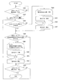
又、図3に示すように、熱量制御手段(自動制御装置)や図示しない各種の温度センサにより、空冷ヒートポンプ4の空気熱交換機の空気吸い込み温度が例えば25度以上35度以下になるように制御される。   In addition, as shown in FIG. 3, the air intake temperature of the air heat exchanger of the air-cooled heat pump 4 is controlled to be, for example, 25 ° C. or more and 35 ° C. or less by a heat control means (automatic control device) or various temperature sensors (not shown). Is done.

即ち、自動制御手段は、空冷ヒートポンプ4の起動指令を監視し(ステップS1)、当該起動指令がONである場合、空冷ヒートポンプ4の運転を開始する(ステップS2)。更に、自動制御手段は、外気温度が25度未満でないと(ステップS3でNO)、工場換気ファン24を停止すると共に(ステップS4)、空冷ヒートポンプ4の停止指令を監視し(ステップS5)、当該停止指令がONである場合、工場換気ファン24の運転を停止して処理を終了する(ステップS6)。一方、当該停止指令がONでない場合には、ステップS3からの処理を繰り返す。   That is, the automatic control means monitors the start command of the air cooling heat pump 4 (step S1), and starts the operation of the air cooling heat pump 4 when the start command is ON (step S2). Further, if the outside air temperature is not less than 25 degrees (NO in step S3), the automatic control means stops the factory ventilation fan 24 (step S4) and monitors the stop command for the air cooling heat pump 4 (step S5). If the stop command is ON, the operation of the factory ventilation fan 24 is stopped and the process is terminated (step S6). On the other hand, if the stop command is not ON, the processing from step S3 is repeated.

そして、自動制御手段は、外気温度が25度未満であると(ステップS3でYES)、工場換気ファン24における吸い込み温度が外気温度より5度を超えて高いかを判定し(ステップS7)、ステップS7でYESであれば、工場換気ファン24の運転を開始して(ステップS8)、空冷ヒートポンプ4の空気熱交換機の空気吸い込み温度(排温風Bの温度)が25度以下であるか否かを確認する(ステップS9)。一方、自動制御手段は、工場換気ファン24の吸い込み温度が外気温度より5度を超えて高くなければ(ステップS7でNO)、上述のステップS4以降の処理を実行する。   When the outside air temperature is less than 25 degrees (YES in step S3), the automatic control means determines whether the suction temperature in the factory ventilation fan 24 is higher than the outside air temperature by more than 5 degrees (step S7), and step If YES in S7, the operation of the factory ventilation fan 24 is started (step S8), and whether or not the air suction temperature (temperature of the exhaust air B) of the air heat exchanger of the air-cooling heat pump 4 is 25 degrees or less. Is confirmed (step S9). On the other hand, if the suction temperature of the factory ventilation fan 24 is not higher than the outside air temperature by more than 5 degrees (NO in step S7), the automatic control means executes the processing from step S4 described above.

自動制御手段は、空冷ヒートポンプ4の空気吸い込み温度が25度以下である場合(ステップS9でYES)、当該空気吸い込み温度が30度以上となるまで(ステップS10,S12)、工場換気ファン24をインバーターにより風量を徐々に増加させ(ステップS11)、上記のステップS5に移行する。   When the air suction temperature of the air-cooled heat pump 4 is 25 degrees or less (YES in step S9), the automatic control means turns the factory ventilation fan 24 into an inverter until the air suction temperature reaches 30 degrees or more (steps S10 and S12). Thus, the air volume is gradually increased (step S11), and the process proceeds to step S5.

一方、自動制御手段は、空冷ヒートポンプ4の空気吸い込み温度が25度以下でない場合(ステップS9でNO)、当該温度が35度以上であるか判断する(ステップS13)。自動制御手段は、当該温度が35度以上でない場合(ステップS13でNO)、上記ステップS5に移行する。   On the other hand, if the air suction temperature of the air-cooled heat pump 4 is not 25 degrees or less (NO in step S9), the automatic control means determines whether the temperature is 35 degrees or more (step S13). When the temperature is not 35 degrees or higher (NO in step S13), the automatic control unit proceeds to step S5.

一方、自動制御手段は、空冷ヒートポンプ4の空気吸い込み温度が35度以上である場合(ステップS13でYES)、当該空気吸い込み温度が35度以下となるまで(ステップS14,S16)、工場換気ファン24をインバーターにより風量を徐々に低下させ(ステップS15)、上記のステップS5に移行する。   On the other hand, when the air suction temperature of the air-cooled heat pump 4 is 35 ° C. or higher (YES in step S13), the automatic controller means the factory ventilation fan 24 until the air suction temperature becomes 35 ° C. or lower (steps S14 and S16). The air volume is gradually reduced by the inverter (step S15), and the process proceeds to the above step S5.

このような媒体温度調整システム21は、塗装工場Fで用いられる脱脂液を加温する温水を加温する空冷ヒートポンプ4と、塗装工場Fに属する乾燥炉Dや前処理工程等からの熱を、空冷ヒートポンプ4の空気熱交換機に導くダクト22ないし工場換気ファン24を有する。   Such a medium temperature adjustment system 21 includes heat from the air-cooled heat pump 4 that warms the hot water that heats the degreasing liquid used in the coating factory F, and the heat from the drying furnace D and the pretreatment process belonging to the coating factory F, A duct 22 leading to an air heat exchanger of the air cooling heat pump 4 or a factory ventilation fan 24 is provided.

従って、第1形態と同様に、空冷ヒートポンプ4のCOPを良好なものとし、加熱能力の高い状態で運転することができ、十分な加熱をしながら効率の良い運転を行うことができる。   Therefore, as in the first embodiment, the COP of the air-cooled heat pump 4 can be made good, and the operation can be performed with a high heating capacity, and an efficient operation can be performed with sufficient heating.

[第3形態]
図4は第3形態に係る媒体温度調整システム31の模式図であって、媒体温度調整システム31は、外気案内手段が追加される他、第1形態と変更例も含め同様である。
[Third embodiment]
FIG. 4 is a schematic diagram of the medium temperature adjustment system 31 according to the third embodiment. The medium temperature adjustment system 31 is the same as that of the first embodiment and the modified example except that an outside air guiding unit is added.

即ち、塗装工場Fの外部から内部における空冷ヒートポンプ4の空気熱交換機の手前にかけて、外気Aを通すダクト32が設置されており、ダクト32にはブロワー34が設けられている。ブロワー34は、ダクト32における空冷ヒートポンプ4側に設置されており、空気熱交換機に外気Aを当てて(暖気Hと共に)吸わせることが可能である。なお、空冷ヒートポンプ4は、温水を供給する(加温を行う)に当たっては、空気熱交換機における空気吸い込み温度が所定温度(例えば40度)以下となっている必要があり、当該所定温度を超えると、空冷ヒートポンプ4の冷媒高圧異常の保護装置が作動して空冷ヒートポンプ4の運転が停止される。なお、ダクト32あるいはブロワー34において、外気Aの流量等を調整する外気熱量調節手段を設置することができる。   That is, a duct 32 through which the outside air A passes is installed from the outside of the painting factory F to the front of the air heat exchanger of the air-cooled heat pump 4 inside, and the blower 34 is provided in the duct 32. The blower 34 is installed on the side of the air cooling heat pump 4 in the duct 32, and can be sucked by applying external air A (along with warm air H) to the air heat exchanger. Note that the air cooling heat pump 4 needs to have the air suction temperature in the air heat exchanger not more than a predetermined temperature (for example, 40 degrees) when supplying hot water (heating), and if it exceeds the predetermined temperature The refrigerant high pressure abnormality protection device of the air cooling heat pump 4 is activated, and the operation of the air cooling heat pump 4 is stopped. In the duct 32 or the blower 34, an outside air calorie adjusting means for adjusting the flow rate of the outside air A or the like can be installed.

このような媒体温度調整システム31は、次に説明するように動作する。   Such a medium temperature adjustment system 31 operates as described below.

例えば、脱脂槽2の脱脂液を60度に保温するための加温負荷が73kWであり、塗装工場F内は乾燥炉D(120度)の屋内設置等により60度であり、暖気Hが50度であったとする(夏季等)。この場合、空冷ヒートポンプ4からは温水73kW(70度)の供給が必要であるが、空冷ヒートポンプ4の空気熱交換機に50度の暖気Hが当たっており(50度の暖気Hを吸わせており)、空冷ヒートポンプ4への電気Vの入力は27kWで済むものの、そのままでは空冷ヒートポンプ4の運転が停止されることとなる。しかし、ダクト32ないしブロワー34により暖気Hに対して35度の外気Aが混入されるため、空気熱交換機における空気吸い込み温度が40度(所定温度)以下となり、空冷ヒートポンプ4の保護装置を作動させる事態の発生が防止される。   For example, the heating load for keeping the degreasing liquid in the degreasing tank 2 at 60 degrees is 73 kW, the inside of the coating factory F is 60 degrees by the indoor installation of the drying furnace D (120 degrees), and the warm air H is 50. Suppose it was a degree (summer, etc.). In this case, it is necessary to supply hot water 73 kW (70 degrees) from the air-cooled heat pump 4, but the air heat exchanger of the air-cooled heat pump 4 receives 50 degrees warm air H (50 degrees warm air H is sucked). ) Although the input of electricity V to the air-cooling heat pump 4 is 27 kW, the operation of the air-cooling heat pump 4 is stopped as it is. However, since the outside air A of 35 degrees is mixed with the warm air H by the duct 32 or the blower 34, the air suction temperature in the air heat exchanger becomes 40 degrees (predetermined temperature) or less, and the protection device of the air cooling heat pump 4 is activated. The occurrence of the situation is prevented.

なお、外気案内手段又はこれに接続された自動制御装置は、空冷ヒートポンプ4の空気吸い込み温度(暖気Hの温度)を図示しない温度センサ等により監視して、当該温度が保護装置の作動する所定温度未満の特定温度(例えば35度)以上となると、ブロワー34を起動して外気Aを導入するようにすることができ、又当該特定温度あるいはこれより低い一定温度(例えば30度)未満となると、ブロワー34を停止して外気Aの導入を止めるようにすることができる。なお、自動制御装置は、空冷ヒートポンプ4の空気吸い込み温度に代えて、あるいはこの温度と共に、空冷ヒートポンプ4の冷媒圧力に基づいて外気案内手段の起動や停止を行うことができる。又、ブロワー34は、インバーターにより風量を制御しても良い。更に、ダクト32を省略する目的のため、工場側面にブロワー24を設置し、ブロワー24から送られた外気が空冷ヒートポンプ4の空気熱交換機に吸い込まれるように空冷ヒートポンプ4を配置しても良い。   The outside air guiding means or the automatic control device connected thereto monitors the air suction temperature (the temperature of the warm air H) of the air-cooled heat pump 4 with a temperature sensor or the like (not shown), and the temperature is a predetermined temperature at which the protection device operates. When the temperature is less than a specific temperature (for example, 35 degrees) or more, the blower 34 can be activated to introduce the outside air A, and when the temperature is less than the specific temperature or a constant temperature lower than the specific temperature (for example, 30 degrees), It is possible to stop the blower 34 and stop the introduction of the outside air A. Note that the automatic control device can start and stop the outside air guiding means based on the refrigerant pressure of the air-cooled heat pump 4 instead of or together with the air suction temperature of the air-cooled heat pump 4. The blower 34 may control the air volume by an inverter. Further, for the purpose of omitting the duct 32, the blower 24 may be installed on the side of the factory, and the air-cooled heat pump 4 may be arranged so that the outside air sent from the blower 24 is sucked into the air heat exchanger of the air-cooled heat pump 4.

以上の第3形態の媒体温度調整システム31は、第1形態と同様に成り、特に空冷ヒートポンプ4の空気熱交換機に外気A(冷気)を(暖気Hに合わせて)導く外気案内手段(冷気案内手段)を備えている。   The medium temperature adjustment system 31 of the above third embodiment is the same as that of the first embodiment, and in particular, the outside air guiding means (cold air guide) for guiding the outside air A (cold air) (according to the warm air H) to the air heat exchanger of the air cooling heat pump 4. Means).

従って、第1形態の媒体温度調整システム31と同様の効果を奏し、更に暖気Hの温度が空冷ヒートポンプ4の空気吸い込み温度として高すぎる場合には暖気Hに外気A(冷気)を混合することで空冷ヒートポンプ4の保護装置が作動する事態を防止して、空冷ヒートポンプ4の加温運転を(効率の良い状態で)継続させることができる。   Therefore, the same effect as that of the medium temperature adjustment system 31 of the first embodiment is obtained, and when the temperature of the warm air H is too high as the air suction temperature of the air-cooled heat pump 4, the warm air H is mixed with the outside air A (cold air). The situation where the protection device of the air cooling heat pump 4 is activated can be prevented, and the heating operation of the air cooling heat pump 4 can be continued (in an efficient state).

[第4形態]
第4形態に係る媒体温度調整システム41は、外気案内手段に代えて冷却手段としての間接散水冷却装置が追加される他、第3形態と変更例も含め同様である。
[Fourth form]
The medium temperature adjustment system 41 according to the fourth embodiment is the same as the third embodiment and the modified example, in addition to the addition of an indirect water spray cooling device as a cooling means instead of the outside air guiding means.

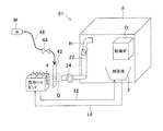
即ち、図5に示すように、乾燥炉Dと空冷ヒートポンプ4との間には、散水により気体を冷却する間接散水冷却装置42が設置されている。間接散水冷却装置42には、水Wの流量(熱量)を調節可能な調節器としての散水弁44を備えた水供給器46が接続されていると共に、水Wを排出する排水ピットPが接続されている。水供給器46は、図示しないタンク等にある水Wを間接散水冷却装置42に供給する。間接散水冷却装置42は、ここではマット状の本体に水供給器46からの水Wを伝わせて流下させるものであり、当該本体に乾燥炉Dからの暖気Hが通るようにして暖気Hを水Wの気化熱等により冷却して冷却エアCとするものである。暖気Hに冷却を施した冷却エアCは、空冷ヒートポンプ4の空気吸い込み口において吸引され、空気熱交換機に当てられる。なお、散水弁44は図示しない自動制御装置に接続されて良い。   That is, as shown in FIG. 5, an indirect water spray cooling device 42 that cools the gas by water spray is installed between the drying furnace D and the air cooling heat pump 4. Connected to the indirect sprinkler cooling device 42 is a water supply 46 having a sprinkler valve 44 as a regulator capable of adjusting the flow rate (heat quantity) of the water W, and a drain pit P for discharging the water W. Has been. The water supplier 46 supplies water W in a tank (not shown) or the like to the indirect sprinkler cooling device 42. Here, the indirect water spray cooling device 42 causes the water W from the water supply device 46 to flow down to the mat-shaped main body, and flows the warm air H from the drying furnace D through the main body. The cooling air C is cooled by the heat of vaporization of the water W or the like. The cooling air C that has cooled the warm air H is sucked at the air suction port of the air-cooling heat pump 4 and applied to the air heat exchanger. The watering valve 44 may be connected to an automatic control device (not shown).

このような媒体温度調整システム41は、例えば次に説明するように動作する。   Such a medium temperature adjustment system 41 operates as described below, for example.

即ち、図6に示すように、自動制御装置は、空冷ヒートポンプ4の起動指令がONである場合(ステップS41でYES)、空冷ヒートポンプ4の運転を開始する(ステップS42)。そして、自動制御装置は、初期設定として(ステップS43でNO)、散水弁44を所定時間(2分間)全開した後(ステップS44〜S46)、散水弁44を閉止して、ステップS48に移行する。このような動作につき更に詳述すると、工場内に空冷ヒートポンプ4を設置した場合、埃や油分等が間接散水冷却装置42に付くことから、定期的に洗い流すこととし、間接散水冷却装置42の詰まりによる性能低下ないし能力低下を防止するものである。又、定期的な散水を実行することにより、死に水の発生を防止し、サビ等による間接散水冷却装置42の詰まりを防止する。なお、後述の第5,7形態でも、このような動作による同様の作用が現れる。即ち、空冷ヒートポンプ4の空気熱交換機に直接定期的に散水することで、空気熱交換機に付着した埃や油分等を洗い流し、性能低下・能力低下が防止される。   That is, as shown in FIG. 6, when the activation command for the air cooling heat pump 4 is ON (YES in step S41), the automatic control device starts the operation of the air cooling heat pump 4 (step S42). Then, as an initial setting (NO in step S43), the automatic control device fully opens the watering valve 44 for a predetermined time (2 minutes) (steps S44 to S46), closes the watering valve 44, and proceeds to step S48. . This operation will be described in further detail. When the air-cooled heat pump 4 is installed in the factory, dust and oil are attached to the indirect water spray cooling device 42, and therefore, the indirect water spray cooling device 42 is clogged. This prevents performance degradation or capacity degradation due to the above. In addition, by periodically performing watering, generation of water is prevented and clogging of the indirect watering cooling device 42 due to rust or the like is prevented. In the fifth and seventh embodiments, which will be described later, a similar effect due to such an operation appears. That is, by directly spraying water directly on the air heat exchanger of the air-cooling heat pump 4, dust, oil, etc. adhering to the air heat exchanger are washed away, and performance degradation and performance degradation are prevented.

自動制御装置は、ステップS48において、空冷ヒートポンプ4の空気熱交換機における空気吸い込み温度が特定温度(38度)以上であるか否かを確認する。自動制御装置は、空気吸い込み温度が特定温度以上でなければ(ステップS48でNO)、後述のステップS53に移行する。   In step S48, the automatic control device checks whether or not the air suction temperature in the air heat exchanger of the air-cooled heat pump 4 is equal to or higher than a specific temperature (38 degrees). If the air suction temperature is not equal to or higher than the specific temperature (NO in step S48), the automatic control device proceeds to step S53 described later.

一方、自動制御装置は、空気吸い込み温度が特定温度以上であれば(ステップS48でYES)、空気吸い込み温度が特定温度あるいはこれより低い所定温度(ここでは35度)以下となるまで、散水弁44を全開する(ステップS49〜S51)。そして、自動制御装置は、空気吸い込み温度が所定温度等となると、散水弁44を閉止して、ステップS53に移行する。   On the other hand, if the air suction temperature is equal to or higher than the specific temperature (YES in step S48), the automatic control device determines that the water suction valve 44 is used until the air suction temperature is equal to or lower than the specific temperature or a predetermined temperature lower than this (35 degrees in this case). Is fully opened (steps S49 to S51). Then, when the air suction temperature reaches a predetermined temperature or the like, the automatic control device closes the water spray valve 44 and proceeds to step S53.

自動制御装置は、ステップS53において、空冷ヒートポンプ4の停止指令を監視し、指令が「ON」であれば処理を終了し、そうでなければステップS43以降の処理を継続する。   In step S53, the automatic control device monitors a stop command for the air-cooling heat pump 4. If the command is “ON”, the automatic control device ends the process. If not, the process continues from step S43.

以上の第4形態の媒体温度調整システム41は、空冷ヒートポンプ4の空気熱交換機に導かれる乾燥炉Dからの暖気Hを冷却可能な間接散水冷却装置42を有するので、第3形態と同様に、暖気Hを空冷ヒートポンプ4の保護装置が働かない状態まで冷却することができ、空冷ヒートポンプ4による効率の良好な脱脂槽2の加温を夏季等において継続することができる。   Since the medium temperature adjustment system 41 of the fourth embodiment described above has the indirect water spray cooling device 42 capable of cooling the warm air H from the drying furnace D led to the air heat exchanger of the air-cooling heat pump 4, as in the third embodiment, The warm air H can be cooled to a state where the protection device of the air-cooling heat pump 4 does not work, and heating of the degreasing tank 2 with good efficiency by the air-cooling heat pump 4 can be continued in summer and the like.

なお、暖気Hに係る冷却手段を間接散水冷却装置42としているため、冷却のための水W(冷媒)が塗装工場F内に飛散する事態を防止することができ、水Wを無駄なく利用して効率の良い冷却に寄与することができる。   In addition, since the cooling means related to the warm air H is the indirect water spray cooling device 42, it is possible to prevent the water W (refrigerant) for cooling from being scattered in the painting factory F, and to use the water W without waste. Can contribute to efficient cooling.

[第5形態]
図7は第5形態に係る媒体温度調整システム51の模式図であって、媒体温度調整システム51は、乾燥炉Dからの暖気Hを冷却する冷却手段が自動散水装置52となっている他は、第4形態と変更例も含め同様である。
[Fifth embodiment]
FIG. 7 is a schematic diagram of the medium temperature adjustment system 51 according to the fifth embodiment, except that the medium temperature adjustment system 51 is configured such that the cooling means for cooling the warm air H from the drying furnace D is an automatic watering device 52. The fourth embodiment and the modification are the same.

即ち、媒体温度調整システム51は、空冷ヒートポンプ4の空気熱交換機に対して水Wを散水する自動散水装置52を備えている。自動散水装置52には、水Wの流量(熱量)を調節可能な調節器としての散水弁54を備えた水供給器56が接続されている。水供給器46は、図示しない水道配管・工業用水配管・散水タンク等にある水Wを自動散水装置52に供給する。なお、空冷ヒートポンプ4による脱脂液の加温に代えて、又はこれと共に、空調のための加温や乾燥工程における温風発生用の加温又はこれらの組合せ等を行うことができる。   That is, the medium temperature adjustment system 51 includes an automatic watering device 52 that sprays water W to the air heat exchanger of the air-cooling heat pump 4. The automatic watering device 52 is connected to a water supply device 56 having a watering valve 54 as a regulator capable of adjusting the flow rate (heat amount) of the water W. The water supplier 46 supplies water W in a water pipe, industrial water pipe, watering tank, etc. (not shown) to the automatic watering device 52. Instead of or in addition to the heating of the degreasing liquid by the air cooling heat pump 4, heating for air conditioning, warming for generating hot air in the drying process, or a combination thereof can be performed.

このような媒体温度調整システム51は、第4形態と同様に動作し、例えば空冷ヒートポンプ4の空気熱交換機における空気吸い込み温度が特定温度以上である場合に、所定温度となるまで自動散水装置52により当該空気熱交換機に対して水Wを吹き付けることで、当該空気熱交換機において吸い込まれる暖気Hを気化熱等により冷却し、保護装置の作動による空冷ヒートポンプ4の自動停止を回避してその運転が継続される。   Such a medium temperature adjustment system 51 operates in the same manner as in the fourth embodiment. For example, when the air suction temperature in the air heat exchanger of the air-cooled heat pump 4 is equal to or higher than a specific temperature, the automatic watering device 52 performs the operation until the predetermined temperature is reached. By blowing water W on the air heat exchanger, the warm air H sucked in the air heat exchanger is cooled by vaporization heat, etc., and the automatic cooling of the air cooling heat pump 4 due to the operation of the protective device is avoided and the operation is continued. Is done.

以上の第5形態の媒体温度調整システム51では、第4形態と同様、空冷ヒートポンプ4の空気吸い込み温度を調節して空冷ヒートポンプ4の運転を継続させ、効率の良好な脱脂槽2の加温を持続させることができる。又、空冷ヒートポンプ4の空気熱交換機に水W(媒体)を吹き付けることで当該空気熱交換機の汚れ等を落とすことができ、夏季等はもちろん、冬季等においても一時的に散水することで当該空気熱交換機に付着した埃を洗浄し、空冷ヒートポンプ4における熱交換の効率低下や故障を防止することができる。そして、夏季等においては、空冷ヒートポンプ4の空気吸い込み温度の低下と空気熱交換機の洗浄とを同時に行うことができ、空冷ヒートポンプ4による加温を極めて効率良く実行することができる。   In the medium temperature adjustment system 51 of the fifth embodiment described above, as in the fourth embodiment, the air suction temperature of the air-cooling heat pump 4 is adjusted to continue the operation of the air-cooling heat pump 4, and the efficient degreasing tank 2 is heated. Can last. In addition, the air heat exchanger 4 of the air-cooled heat pump 4 can be sprayed with water W (medium) to remove dirt, etc., and the air heat exchanger 4 can be temporarily sprinkled in winter as well as in summer. The dust adhering to the heat exchanger can be washed, and the efficiency reduction and failure of the heat exchange in the air-cooled heat pump 4 can be prevented. In summer and the like, the air suction heat pump 4 can be lowered in air suction temperature and the air heat exchanger can be cleaned at the same time, and heating by the air cooling heat pump 4 can be performed very efficiently.

なお、第5形態の変更例として、次に説明するものがある。即ち、中間季においても暖房を要する空調の場合等に、業務用パッケージエアコン(空冷ヒートポンプ4)に散水装置を取り付ける。一般的な業務用パッケージエアコン(空調用の空冷ヒートポンプ4)は、外気温度(空気熱交換機の吸い込み温度)が規定温度(例えば15度)を超えるとヒートポンプサイクルが成り立たずに運転不能となる。そこで、空気熱交換機の吸い込み空気温度を規定温度以下に冷やして業務用パッケージエアコンを運転可能とするため、散水装置を取り付け、散水により吸い込み空気を冷却する。このような散水装置の設置により、外気温度が規定温度を超えていても、業務用パッケージエアコン(空冷ヒートポンプ4)の運転を継続することができる。例えば、28度等の特定温度に年中保持する恒温室における空調においては、外気温度15度以上の中間季でも暖房が必要であるところ、一般的な業務用パッケージエアコンをそのまま設置したのではこのような空調が行えない(中間季に運転が停止してしまう)。そこで散水装置により空気熱交換機の導入空気温度を下げ、外気温度15度以上の中間季でも(散水量ないし冷却量の調整により)吸い込み空気温度を15度以下とし、一般的な業務用パッケージエアコンでも運転可能として、コストに配慮しつつ恒温室の空調を的確に継続して行うことが可能となる。   In addition, there exists what is demonstrated below as a modification of a 5th form. That is, in the case of air conditioning that requires heating even in the middle season, a watering device is attached to the commercial packaged air conditioner (air-cooled heat pump 4). A general business packaged air conditioner (air-cooling heat pump 4 for air conditioning) becomes inoperable because a heat pump cycle is not realized if the outside air temperature (suction temperature of the air heat exchanger) exceeds a specified temperature (for example, 15 degrees). Therefore, in order to cool the intake air temperature of the air heat exchanger to a specified temperature or less so that the commercial packaged air conditioner can be operated, a watering device is attached and the suctioned air is cooled by watering. By installing such a watering device, it is possible to continue the operation of the commercial package air conditioner (air-cooled heat pump 4) even if the outside air temperature exceeds the specified temperature. For example, in air conditioning in a temperature-controlled room that is kept at a specific temperature such as 28 degrees throughout the year, heating is necessary even in the mid-season when the outside air temperature is 15 degrees or higher. Air conditioning is not possible (operation stops in the middle season). Therefore, the air temperature of the air heat exchanger is lowered by the watering device, and the intake air temperature is made 15 degrees or less (by adjusting the watering amount or cooling amount) even in the mid season when the outside air temperature is 15 degrees or more. As operation is possible, it becomes possible to continue air conditioning of the temperature-controlled room accurately and in consideration of cost.

[第6形態]
図8は第6形態に係る媒体温度調整システム61の模式図であって、媒体温度調整システム61は、第2形態及び第4形態を組み合わせるようにして成る。
[Sixth form]
FIG. 8 is a schematic diagram of the medium temperature adjustment system 61 according to the sixth embodiment. The medium temperature adjustment system 61 is configured by combining the second embodiment and the fourth embodiment.

即ち、媒体温度調整システム61は、塗装工場Fに属する暖気Hを排温風Bとして空冷ヒートポンプ4の空気熱交換機に導くダクト22及び工場換気ファン24を備えていると共に、工場換気ファン24と空気熱交換機の間に、排温風Bを冷却可能な間接散水冷却装置42を備えている。   That is, the medium temperature adjustment system 61 includes the duct 22 and the factory ventilation fan 24 that guide the warm air H belonging to the painting factory F to the air heat exchanger of the air-cooling heat pump 4 as the exhaust air B, and the factory ventilation fan 24 and the air. Between the heat exchangers, an indirect water spray cooling device 42 capable of cooling the exhaust air B is provided.

このような媒体温度調整システム61は、第2形態や第4形態と同様に動作する。即ち、塗装工場Fの暖気Hを排温風Bとして空冷ヒートポンプ4の空気熱交換機に案内することで空冷ヒートポンプ4の効率良い運転を可能とすると共に、空冷ヒートポンプ4の空気熱交換機のための保護装置が作動し得る程に排温風Bが高温であるにもかかわらず工場換気ファン24のインバーター制御の追従遅れ発生時等により風量調整が上手くいかない場合等に、間接散水冷却装置42を作動して排温風Bを保護装置が作動しない温度まで冷却し、空冷ヒートポンプ4の運転を継続する。   Such a medium temperature adjustment system 61 operates in the same manner as the second and fourth embodiments. In other words, the warm air H of the coating factory F is guided to the air heat exchanger of the air-cooled heat pump 4 as the exhaust air B, so that the air-cooled heat pump 4 can be operated efficiently and the air heat exchanger 4 is protected for the air heat exchanger. The indirect sprinkler cooling device 42 is activated when the exhaust air flow B is so hot that the device can operate, but the air flow adjustment is not successful due to the occurrence of a delay in the follow-up control of the inverter of the factory ventilation fan 24. Then, the exhaust warm air B is cooled to a temperature at which the protective device does not operate, and the operation of the air cooling heat pump 4 is continued.

[第7形態]
図9は第7形態に係る媒体温度調整システム71の模式図であって、媒体温度調整システム61は、第2形態及び第5形態を組み合わせるようにして成る。
[Seventh form]
FIG. 9 is a schematic diagram of the medium temperature adjustment system 71 according to the seventh embodiment, and the medium temperature adjustment system 61 is configured by combining the second embodiment and the fifth embodiment.

即ち、媒体温度調整システム71は、塗装工場Fに属する暖気Hを排温風Bとして空冷ヒートポンプ4の空気熱交換機に導くダクト22及び工場換気ファン24を備えていると共に、空冷ヒートポンプ4の空気熱交換機に対して水Wを散水する自動散水装置52を備えている。   That is, the medium temperature adjustment system 71 includes the duct 22 and the factory ventilation fan 24 that guide the warm air H belonging to the painting factory F to the air heat exchanger of the air-cooling heat pump 4 as exhaust air B, and the air heat of the air-cooling heat pump 4. An automatic watering device 52 for spraying water W to the exchange is provided.

このような媒体温度調整システム71は、第2形態や第5形態と同様に動作する。即ち、塗装工場Fの暖気Hを排温風Bとして空冷ヒートポンプ4の空気熱交換機に案内することで空冷ヒートポンプ4の効率良い運転を可能とすると共に、空冷ヒートポンプ4の空気熱交換機のための保護装置が作動し得る程に排温風Bが高温であるにもかかわらず工場換気ファン24のインバーター制御の追従遅れ発生時等により風量調整が上手くいかない場合等に、自動散水装置52を作動して排温風Bを保護装置が作動しない温度まで冷却し、空冷ヒートポンプ4の運転を継続する。又、媒体温度調整システム61では、自動散水装置52を作動することにより空冷ヒートポンプ4の空気熱交換機に付着した埃の洗浄を実施することができ、空冷ヒートポンプ4の効率低下や故障の防止をすることができる。   Such a medium temperature adjustment system 71 operates in the same manner as the second and fifth embodiments. In other words, the warm air H of the coating factory F is guided to the air heat exchanger of the air-cooled heat pump 4 as the exhaust air B, so that the air-cooled heat pump 4 can be operated efficiently and the air heat exchanger 4 is protected for the air heat exchanger. The automatic watering device 52 is activated when the exhaust air flow B is high enough to operate the device but the air flow adjustment is not successful due to the occurrence of a delay in the follow-up control of the inverter of the factory ventilation fan 24. Then, the exhaust air B is cooled to a temperature at which the protective device does not operate, and the operation of the air cooling heat pump 4 is continued. Moreover, in the medium temperature control system 61, the dust adhering to the air heat exchanger of the air-cooling heat pump 4 can be cleaned by operating the automatic watering device 52, and the efficiency of the air-cooling heat pump 4 is prevented from being reduced or broken. be able to.

[第8形態]
図10は第8形態に係る媒体温度調整システム81の模式図であって、媒体温度調整システム61は、部品工場F2における洗浄工程に配置され、空冷ヒートポンプ4が部品洗浄のための洗浄液の入った洗浄槽82を加温する他は、第1形態と同様に成る。
[Eighth form]
FIG. 10 is a schematic diagram of the medium temperature adjustment system 81 according to the eighth embodiment. The medium temperature adjustment system 61 is arranged in the cleaning process in the parts factory F2, and the air-cooled heat pump 4 contains cleaning liquid for cleaning parts. Except for heating the washing tank 82, it is the same as the first embodiment.

即ち、媒体温度調整システム81では、部品工場F2に属する乾燥炉Dからの暖気Hが空冷ヒートポンプ4の空気熱交換機に適用され、空冷ヒートポンプ4は、供給パイプ12や戻りパイプ14を介して温水を循環させることにより洗浄槽82を加温する。   That is, in the medium temperature adjustment system 81, the warm air H from the drying furnace D belonging to the parts factory F2 is applied to the air heat exchanger of the air cooling heat pump 4, and the air cooling heat pump 4 supplies hot water via the supply pipe 12 and the return pipe 14. The washing tank 82 is heated by circulation.

このような媒体温度調整システム81は、例えば洗浄液を60度に保持するため空冷ヒートポンプ4から70度の温水を供給する一方、120度の乾燥炉Dから発生する25度の暖気Hを空冷ヒートポンプ4の空気熱交換機に吸わせる場合、図11の表における「第8形態」の欄に示すような動作を行い、後述する「従来方式」や「屋外設置方式」と比較して効率の良い動作を行う。   Such a medium temperature adjustment system 81 supplies, for example, hot water of 70 degrees from the air-cooled heat pump 4 to keep the cleaning liquid at 60 degrees, while the air-cooled heat pump 4 supplies 25 degrees of warm air H generated from the 120-degree drying furnace D. When the air heat exchanger is used, the operation shown in the column of “Eighth form” in the table of FIG. 11 is performed, and the operation is more efficient than the “conventional method” and “outdoor installation method” described later. Do.

即ち、洗浄槽82を60度に保持するための加温負荷を夏季(6〜9月)15kW/時(kW/h)、中間季(4,5,10,11月)30kW/h、冬季(12〜3月)60kW/hとする。又、都市ガスで加温する蒸気ボイラのみで洗浄槽82を加温する方式を従来方式とし、単に屋外設置した空冷ヒートポンプ4で洗浄槽82を加温し、加温能力不足時に都市ガスで加温する蒸気ボイラを併用する方式(図1(b)に対応する方式)を屋外設置方式とする。更に、屋外設置方式の空冷ヒートポンプや第8形態の空冷ヒートポンプ4の加熱能力(加温能力)やCOPは、最高出湯温度が70度程度である高温出湯型ヒートポンプ給湯器に係るものとしている。加えて、当該蒸気ボイラーの効率を85%とし、CO排出係数は、都市ガスについて、地球温暖化対策の推進に関する法律施行令及び特定排出者の事業活動に伴う温室効果ガスの排出量の算定に関する省令を基に環境省が作成した「算定・報告・公表制度における算定方法・排出係数一覧」からの計算値(11000キロカロリー毎ノルマル立方メートル(kcal/Nm),2.3300キログラム(CO)毎ノルマル立方メートル(kg−CO/Nm))を用い、電気について、中部電力株式会社の08年度実績値(860キロカロリー毎キロワット時(kcal/kWh),0.4550kg−CO/kWh)を用いる。 That is, the heating load for maintaining the cleaning tank 82 at 60 degrees is 15 kW / hour (kW / h) in the summer (June to September), 30 kW / h in the middle (4, 5, October, November), winter (December to March) 60 kW / h. In addition, the method of heating the cleaning tank 82 only with a steam boiler that is heated with city gas is a conventional method, and the cleaning tank 82 is simply heated with the air-cooled heat pump 4 installed outdoors, and is heated with city gas when the heating capacity is insufficient. A method using a steam boiler for warming (a method corresponding to FIG. 1B) is an outdoor installation method. Furthermore, the heating capacity (heating capacity) and COP of the air cooling heat pump of the outdoor installation type and the air cooling heat pump 4 of the eighth embodiment are related to the high temperature hot water type heat pump water heater whose maximum hot water temperature is about 70 degrees. In addition, the efficiency of the steam boiler is assumed to be 85%, and the CO 2 emission factor is calculated based on the enforcement order of the law on the promotion of global warming countermeasures and greenhouse gas emissions associated with the business activities of specified exhausters for city gas. Calculated values from "List of calculation methods / emission factors in calculation / report / publication system" created by the Ministry of the Environment on the basis of the ministerial ordinances concerning (11,000 kilocalories per cubic meter (kcal / Nm 3 ), 2.3300 kilograms (CO 2 ) Using normal cubic meters (kg-CO 2 / Nm 3 )) and using electricity, Chubu Electric Power Co., Ltd.'s 2008 actual values (860 kilocalories per kilowatt hour (kcal / kWh), 0.4550 kg-CO 2 / kWh) are used. .

そして、夏季の1時間内で、従来方式では蒸気ボイラの運転のため1.4Nmの都市ガスを使用し、屋外設置方式では空冷ヒートポンプの空気熱交換機における空気吸い込み温度が35度となるのでCOPが2.7となり5.6kWhの電力を消費し、第8形態では空冷ヒートポンプ4の空気熱交換機に暖気Hを導入せずとも空気吸い込み温度が35度であるため屋外設置方式と同様になる。 Then, within 1 hour in summer, the conventional method uses 1.4 Nm 3 city gas for steam boiler operation, and the outdoor installation method has an air suction temperature of 35 degrees C in the air heat exchanger of the air-cooled heat pump. Becomes 2.7 and consumes 5.6 kWh, and in the eighth embodiment, the air suction temperature is 35 degrees without introducing the warm air H into the air heat exchanger of the air-cooled heat pump 4, so that it is the same as the outdoor installation method.

又、中間季の1時間内で、従来方式では蒸気ボイラの運転のため2.8Nmの都市ガスを使用し、屋外設置方式では空冷ヒートポンプの空気熱交換機における空気吸い込み温度が15度となるのでCOPが2.4となり12.5kWhの電力を消費し、第8形態では空冷ヒートポンプ4の空気熱交換機に暖気Hを導入して空気吸い込み温度を15度から25度へ昇温してCOPが2.7となり、消費電力量が11.1kWhとなる。 Also, within 1 hour of the intermediate season, 2.8 Nm 3 city gas is used for steam boiler operation in the conventional system, and the air suction temperature in the air heat exchanger of the air cooling heat pump is 15 degrees in the outdoor installation system. COP becomes 2.4 and 12.5 kWh of power is consumed. In the eighth embodiment, warm air H is introduced into the air heat exchanger of the air-cooled heat pump 4 to raise the air suction temperature from 15 degrees to 25 degrees and COP becomes 2 .7, and the power consumption is 11.1 kWh.

加えて、冬季の1時間内で、従来方式では、蒸気ボイラの運転のため5.5Nmの都市ガスを使用し、屋外設置方式では、空冷ヒートポンプの空気熱交換機における空気吸い込み温度が5度となるのでCOPが2.1となり23.3kWhの電力を消費すると共に、空冷ヒートポンプのみでは全ての加熱負荷を賄えないため蒸気ボイラーを運転して1.0Nmの都市ガスを使用し、第8形態では、空冷ヒートポンプ4の空気熱交換機に暖気Hを導入して空気吸い込み温度を5度から15度へ昇温してCOPが2.4となり、消費電力は25.0kWhとなって、1台の空冷ヒートポンプ4で全ての加熱負荷が賄える。 In addition, within 1 hour in winter, the conventional method uses 5.5 Nm 3 city gas for steam boiler operation, and the outdoor installation method has an air intake temperature of 5 degrees in the air heat exchanger of the air-cooled heat pump. Therefore, the COP becomes 2.1 and consumes 23.3 kWh of power, and the air cooling heat pump alone cannot cover all the heating loads, so the steam boiler is operated and 1.0 Nm 3 city gas is used. In the embodiment, the warm air H is introduced into the air heat exchanger of the air-cooled heat pump 4 to raise the air suction temperature from 5 degrees to 15 degrees, the COP becomes 2.4, and the power consumption becomes 25.0 kWh. The air cooling heat pump 4 can cover all heating loads.

更に、1日当たりの運転時間や季節毎の運転日数を考慮して季節毎にエネルギー使用量やCO排出量を通算すると、夏季では従来方式でガスが1788Nm・COが4.2トン(ton)、屋外設置方式及び第8形態で電気が7200kWh・COが3.3トン、中間季では従来方式でガスが3664Nm・COが8.5トン、屋外設置方式で電気が16600kWh・COが7.6トン、第8形態で電気が14756kWh・COが6.7トン、冬季では従来方式でガスが7064Nm・COが16.5トン、屋外設置方式でガスが1295Nm・電気が29867kWh・COが電気の13.6トン及びガスの3.0トンを合わせて16.6トン、第8形態で電気が32000kWh・COが14.6トンとなる。 Furthermore, when the amount of energy used and CO 2 emissions are calculated for each season in consideration of the operation time per day and the number of operation days for each season, in the summer the gas is 1788 Nm 3 · CO 2 is 4.2 tons ( ton), the outdoor installation method and the eighth form are 7200 kWh · CO 2 for 3.3 tons, the mid-season gas is 3664 Nm 3 · CO 2 for 8.5 tons, and the outdoor installation method is 16600 kWh · CO 2 7.6 tons electricity 14756KWh · CO 2 6.7 tons eighth embodiment, the gas in a conventional manner in the winter 7064Nm 3 · CO 2 16.5 tons of gas outdoors installation means 1295 3 -Electricity is 29867 kWh · CO 2 is 16.6 tons of electricity and 3.0 tons of gas is combined, 16.6 tons, electricity is 32000 kWh · CO 2 is 14. 6 tons.

そして、各季を合計して年間のエネルギー使用量やCO排出量を割り出すと、CO排出量は従来方式の29.2トンと比較して屋外設置方式で6%削減され(27.4トン)、本発明の第8形態で16%削減される(24.5トン)。又、エネルギー使用量は従来方式の都市ガス12516Nm(原油換算14.9キロリットル)と原油換算量で比較して屋外設置方式では3%増加してしまうが(電気53667kWh・ガス1295Nm・原油換算合計15.3キロリットル)、第8形態で7%削減される(電気53956kWh・原油換算13.9キロリットル)。 When the annual energy consumption and CO 2 emissions are calculated by summing up each season, the CO 2 emissions are reduced by 6% in the outdoor installation method compared to 29.2 tons of the conventional method (27.4). ), Which is reduced by 16% in the eighth embodiment of the present invention (24.5 tons). In addition, the amount of energy used increases by 3% when compared to the conventional city gas 12516 Nm 3 (crude oil equivalent 14.9 kiloliters) and the crude oil equivalent amount (electricity 53667 kWh · gas 1295 Nm 3 · crude oil The total amount is 15.3 kiloliters in terms of conversion), which is reduced by 7% in the eighth mode (electricity: 53,956 kWh, crude oil equivalent: 13.9 kiloliters).

このように、第8形態に係る媒体温度調整システム81にあっても、第1形態と同様、適宜暖気Hを空冷ヒートポンプ4の空気熱交換機に導入することで、空冷ヒートポンプ4のCOPを良好なものとし、加熱能力の高い状態で運転することができ、エネルギー使用量が比較的に少ない状態で多大な加温を施すことができる。しかも、部品工場F2における洗浄工程において洗浄液を加温することに用いることができる。更に、屋外設置方式のように単に空冷ヒートポンプを屋外設置する場合と異なり、蒸気ボイラーを併用する必要が殆どないし、蒸気ボイラーの代わりに2台目の空冷ヒートポンプを設ける必要もなく、初期コストを抑えることができる。   Thus, even in the medium temperature adjustment system 81 according to the eighth embodiment, the COP of the air-cooled heat pump 4 is improved by appropriately introducing the warm air H to the air heat exchanger of the air-cooled heat pump 4 as in the first embodiment. It can be operated with a high heating capacity, and can be heated greatly with a relatively small amount of energy consumption. Moreover, it can be used to heat the cleaning liquid in the cleaning process at the parts factory F2. Furthermore, unlike the case where the air-cooled heat pump is simply installed outdoors as in the case of the outdoor installation method, there is almost no need to use a steam boiler, and it is not necessary to provide a second air-cooled heat pump instead of the steam boiler, thus reducing the initial cost. be able to.

[第9形態]
図12は第9形態に係る媒体温度調整システム91の模式図であって、媒体温度調整システム91は、塗装工場Fに配置され、空冷ヒートポンプ4が脱脂槽2と合わせて化成液の入った化成槽92を加温する他は、第5形態と同様に成る。
[Ninth embodiment]
FIG. 12 is a schematic diagram of the medium temperature adjustment system 91 according to the ninth embodiment. The medium temperature adjustment system 91 is disposed in the coating factory F, and the air-cooled heat pump 4 is combined with the degreasing tank 2 and contains a chemical conversion solution. Except for heating the tank 92, it is the same as the fifth embodiment.

即ち、媒体温度調整システム91では、供給パイプ12から分岐する脱脂液加温用の分岐供給パイプ92を備えると共に、戻りパイプ14から分岐する、脱脂液を熱交換により加温した温水を戻すための分岐戻りパイプ94を備えており、更に空冷ヒートポンプ4の空気熱交換機に対して水Wを散水する自動散水装置52等を備えている。   That is, the medium temperature adjustment system 91 includes a branch supply pipe 92 for heating the degreasing liquid that branches from the supply pipe 12 and returns the warm water that is branched from the return pipe 14 and heated by heat exchange. A branch return pipe 94 is provided, and an automatic watering device 52 for spraying water W to the air heat exchanger of the air cooling heat pump 4 is further provided.

このような媒体温度調整システム91は、例えば脱脂液ないし洗浄液を45度に保持するため空冷ヒートポンプ4から55度の温水を供給する一方、120度の乾燥炉Dから発生する25度の暖気Hを空冷ヒートポンプ4の空気熱交換機に吸わせる場合、図13の表における「第9形態」の欄に示すような動作を行い、第8形態と同様の「従来方式」や「屋外設置方式」と比較して効率の良い動作を行う。   Such a medium temperature adjustment system 91 supplies, for example, hot water of 55 degrees from the air-cooled heat pump 4 in order to keep the degreasing liquid or cleaning liquid at 45 degrees, while warm air H of 25 degrees generated from the drying furnace D of 120 degrees. When sucking into the air heat exchanger of the air-cooled heat pump 4, the operation shown in the column of “9th form” in the table of FIG. 13 is performed, and compared with the “conventional system” and “outdoor installation system” similar to the 8th form. And perform efficient operation.

即ち、脱脂槽2及び化成槽92を45度に保持するための加温負荷を夏季45kW/h・中間季90kW/h・冬季180kW/hとし、屋外設置方式の空冷ヒートポンプや第9形態の空冷ヒートポンプ4の加熱能力やCOPを高外気温度仕様空冷ヒートポンプチラーに係るものとする他は、第8形態と同様にそれぞれの動作を考えることができる。   That is, the heating load for maintaining the degreasing tank 2 and the chemical conversion tank 92 at 45 degrees is 45 kW / h in the summer, 90 kW / h in the intermediate season, and 180 kW / h in the winter, and the outdoor-type air cooling heat pump and the ninth form of air cooling are used. Each operation can be considered in the same manner as in the eighth embodiment except that the heating capacity and COP of the heat pump 4 are related to the high outside air temperature specification air-cooled heat pump chiller.

そして、夏季の1時間で、従来方式ではガス4.1Nmを使用し、屋外設置方式では空冷ヒートポンプの空気熱交換機における空気吸い込み温度が35度となるのでCOPが3.7となり12.2kWhの電力を消費し、第9形態では空冷ヒートポンプ4の空気熱交換機に暖気Hを導入せずとも空気吸い込み温度が35度であるため屋外設置方式と同様になる。 And in summer 1 hour, gas 4.1Nm 3 is used in the conventional system, and in the outdoor installation system, the air suction temperature in the air heat exchanger of the air-cooled heat pump is 35 degrees, so the COP becomes 3.7 and 12.2 kWh. In the ninth embodiment, the air intake temperature is 35 degrees without introducing the warm air H into the air heat exchanger of the air-cooled heat pump 4, so that the ninth embodiment is the same as the outdoor installation method.

又、中間季の1時間で、従来方式ではガス8.3Nmを使用し、屋外設置方式では空冷ヒートポンプの空気熱交換機における空気吸い込み温度が15度となるのでCOPが3.7となり24.3kWhの電力を消費し、第9形態では空冷ヒートポンプ4の空気熱交換機に暖気Hを導入して空気吸い込み温度を15度から25度へ昇温するもののCOPは屋外設置方式における3.7と変わらず、消費電力量も同等となる。 Also, in the middle season, gas 8.3 Nm 3 is used in the conventional system, and in the outdoor installation system, the air suction temperature in the air heat exchanger of the air-cooled heat pump is 15 degrees, so COP is 3.7 and 24.3 kWh In the ninth embodiment, the warm air H is introduced into the air heat exchanger of the air-cooled heat pump 4 to raise the air suction temperature from 15 degrees to 25 degrees, but the COP is the same as 3.7 in the outdoor installation method. The power consumption is also equivalent.

加えて、冬季の1時間で、従来方式ではガス16.6Nmを使用し、屋外設置方式では空気吸い込み温度が5度でCOPが2.9となり50.7kWhの電力を消費すると共に蒸気ボイラーで3.0Nmの都市ガスを使用し、第8形態では空冷ヒートポンプ4の空気熱交換機に暖気Hを導入し空気吸い込み温度を5度から15度へ昇温してCOPが3.7となり、消費電力は48.6kWhとなって、1台の空冷ヒートポンプ4で全ての加熱負荷が賄える。 In addition, in 1 hour in winter, the conventional method uses 16.6 Nm 3 of gas, and the outdoor installation method consumes 50.7 kWh of power with an air suction temperature of 5 degrees, COP of 2.9, and a steam boiler. The city gas of 3.0Nm 3 is used, and in the 8th form, the warm air H is introduced into the air heat exchanger of the air-cooled heat pump 4 and the air suction temperature is raised from 5 degrees to 15 degrees, resulting in a COP of 3.7. The electric power is 48.6 kWh, and all heating loads can be covered by one air-cooled heat pump 4.

更に、1日当たりの運転時間や季節毎の運転日数を考慮して季節毎にエネルギー使用量やCO排出量を通算すると、夏季では従来方式でガスが5364Nm・COが12.5トン、屋外設置方式及び第9形態で電気が15762kWh・COが7.2トン、中間季では従来方式でガスが10933Nm・COが25.6トン、屋外設置方式及び第9形態で電気が32303kWh・COが14.7トン、冬季では従来方式でガスが21192Nm・COが49.4トン、屋外設置方式でガスが3885Nm・電気が64883kWh・COが電気の29.5トン及びガスの9.1トンを合わせて38.6トン、第9形態で電気が62270kWh・COが28.3トンとなる。 In addition, when the amount of energy used and CO 2 emissions are calculated for each season in consideration of the operation time per day and the number of operation days for each season, in the summer the gas is 5364 Nm 3 · CO 2 is 12.5 tons, In the outdoor installation method and the ninth form, electricity is 15762 kWh · CO 2 is 7.2 tons, in the middle season the gas is 10933 Nm 3 · CO 2 is 25.6 tons, in the outdoor installation method and the ninth form, electricity is 32303 kWh · CO 2 14.7 tons gas in a conventional manner in the winter 21192Nm 3 · CO 2 is 49.4 tons, an outdoor installation means 29.5 tons and gas 3885Nm 3 · electricity 64883kWh · CO 2 is electricity The total of 9.1 tons of gas is 38.6 tons, and in the ninth embodiment, electricity is 62270 kWh · CO 2 is 28.3 tons.

そして、各季を合計して年間のエネルギー使用量やCO排出量を割り出すと、CO排出量は従来方式の87.5トンと比較して屋外設置方式で31%削減され(60.4トン)、本発明の第9形態で43%削減される(50.2トン)。又、エネルギー使用量は従来方式の都市ガス37549Nm(原油換算44.7キロリットル)と原油換算量で比較して屋外設置方式で25%削減され(電気112948kWh・ガス3885Nm・原油換算合計33.7キロリットル)、第9形態で36%削減される(電気110335kWh・原油換算28.4キロリットル)。 Then, when the total energy consumption and CO 2 emissions are calculated for each season, CO 2 emissions are reduced by 31% in the outdoor installation method compared to 87.5 tons of the conventional method (60.4 ), Which is reduced by 43% in the ninth embodiment of the present invention (50.2 tons). In addition, the amount of energy used is reduced by 25% when compared to the conventional city gas of 37549 Nm 3 (crude oil equivalent 44.7 kiloliters) and the crude oil equivalent amount (electricity 112948 kWh, gas 3885 Nm 3 and crude oil equivalent total 33). .7 kiloliters), the ninth form reduces 36% (electricity: 11335 kWh / crude oil equivalent: 28.4 kiloliters).

このように、第9形態に係る媒体温度調整システム91にあっても、第5形態と同様、適宜暖気Hを空冷ヒートポンプ4の空気熱交換機に導入することで、空冷ヒートポンプ4のCOPを良好なものとし、加熱能力の高い状態で運転することができ、エネルギー使用量が比較的に少ない状態で多大な加熱を施すことができ、特にCO排出量は従来方式を基準としておよそ半減され、エネルギー使用量は36%も削減される。又、第8形態と同様に、蒸気ボイラーを併用する必要が殆どないし、蒸気ボイラーの代わりに2台目の空冷ヒートポンプを設ける必要もなく、初期コストを抑えることができる。 Thus, even in the medium temperature adjustment system 91 according to the ninth embodiment, the COP of the air-cooled heat pump 4 is improved by appropriately introducing the warm air H to the air heat exchanger of the air-cooled heat pump 4 as in the fifth embodiment. It can be operated with a high heating capacity, and can be heated greatly with a relatively small amount of energy consumption. In particular, the CO 2 emission is reduced to about half that of the conventional method. Usage is reduced by 36%. Further, similarly to the eighth embodiment, it is hardly necessary to use a steam boiler, and it is not necessary to provide a second air-cooled heat pump in place of the steam boiler, so that the initial cost can be suppressed.

[第10形態]
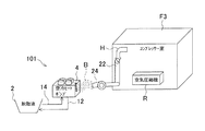
図14は第10形態に係る媒体温度調整システム101の模式図であって、媒体温度調整システム101は、媒体温度調整システム101の空冷ヒートポンプ4がコンプレッサー室F3に配置され、コンプレッサー室F3内の空気圧縮機Rが熱源となりコンプレッサー室F3内の暖気Hがダクト22ないし工場換気ファン24に導かれて排温風Bとなる他は、第2形態と同様に成る。
[Tenth embodiment]
FIG. 14 is a schematic diagram of the medium temperature adjustment system 101 according to the tenth embodiment. In the medium temperature adjustment system 101, the air cooling heat pump 4 of the medium temperature adjustment system 101 is disposed in the compressor chamber F3, and the air in the compressor chamber F3 is shown. The compressor R is used as a heat source, and the warm air H in the compressor chamber F3 is led to the duct 22 or the factory ventilation fan 24 to become the exhaust warm air B, which is the same as in the second embodiment.

このように、媒体温度調整システム101においては、塗装工場から離れた、別の工場としてのあるいは塗装工場に属するコンプレッサー室F3からの暖気Hについても塗装工場に係る空冷ヒートポンプ4の空気熱交換機に排温風Bとして導入することができ、第2形態と同様に、空冷ヒートポンプ4の運転効率を向上することができる。   Thus, in the medium temperature adjustment system 101, the warm air H from the compressor room F3 as a separate factory or belonging to the painting factory is also discharged to the air heat exchanger of the air-cooled heat pump 4 associated with the painting factory. It can introduce | transduce as the warm air B, and can improve the operating efficiency of the air cooling heat pump 4 similarly to the 2nd form.

[第11形態]
図15は第11形態に係る媒体温度調整システム111の模式図であって、媒体温度調整システム111は、空冷ヒートポンプ4が工場F4の暖房を行うため、工場F4内の空気を熱交換により加温する温水を供給することの他は、第10形態と同様に成る。
[Eleventh form]
FIG. 15 is a schematic diagram of the medium temperature adjustment system 111 according to the eleventh embodiment. The medium temperature adjustment system 111 heats the air in the factory F4 by heat exchange because the air cooling heat pump 4 heats the factory F4. It becomes the same as that of the 10th form except supplying warm water.

このように、媒体温度調整システム111においては、コンプレッサー室F3における暖気Hを、工場F4を暖房する空冷ヒートポンプ4の空気熱交換機に吸わせることができ、第10形態と同様に、空冷ヒートポンプ4の運転効率を向上することができる。   Thus, in the medium temperature adjustment system 111, the warm air H in the compressor room F3 can be sucked into the air heat exchanger of the air-cooled heat pump 4 that heats the factory F4. As in the tenth embodiment, the air-cooled heat pump 4 Operation efficiency can be improved.

[第12形態]
図16は第12形態に係る媒体温度調整システム121の模式図であって、媒体温度調整システム111は、暖気Hをダクト22ないし工場換気ファン24により空冷ヒートポンプ4の空気熱交換機に導く点で、第2形態と共通する。
[Twelfth embodiment]
FIG. 16 is a schematic diagram of the medium temperature adjustment system 121 according to the twelfth embodiment, in which the medium temperature adjustment system 111 guides the warm air H to the air heat exchanger of the air-cooled heat pump 4 through the duct 22 or the factory ventilation fan 24. Common to the second form.

媒体温度調整システム121において、暖気Hは、ボイラー室F5内に有り、蒸気供給パイプ122を介して蒸気Tを供給する蒸気ボイラーJが運転中発する熱を熱源とする。空冷ヒートポンプ4は、水道配管・工業用水配管・散水タンク等にある水Wを給水パイプ124を介し受け付け、これを加温し供給パイプ126を介して蒸気ボイラーJに供給する。   In the medium temperature adjustment system 121, the warm air H is in the boiler chamber F5 and uses heat generated during operation of the steam boiler J that supplies the steam T via the steam supply pipe 122 as a heat source. The air-cooling heat pump 4 receives water W in a water pipe, industrial water pipe, watering tank, etc. via a water supply pipe 124, heats it, and supplies it to the steam boiler J via a supply pipe 126.

第12形態に係る媒体温度調整システム121においても、暖気Hを空冷ヒートポンプ4の空気熱交換機に吸わせることができ、第2形態と同様に、空冷ヒートポンプ4の運転効率を向上することができる。又、蒸気ボイラーJの余熱を有効利用して蒸気ボイラーJに加温した水Wを供給することができ、蒸気ボイラーJの効率を向上してエネルギー使用量を低減することができる。更に、蒸気ボイラーJの給水系統に空冷ヒートポンプ4を介装してダクト22・工場換気ファン24を設置するだけで媒体温度調整システム121を構成することができ、コストが少なくて済む。   Also in the medium temperature adjustment system 121 according to the twelfth embodiment, the warm air H can be sucked into the air heat exchanger of the air-cooling heat pump 4, and the operating efficiency of the air-cooling heat pump 4 can be improved as in the second embodiment. Moreover, the warm water W can be supplied to the steam boiler J by effectively using the residual heat of the steam boiler J, and the efficiency of the steam boiler J can be improved and the amount of energy used can be reduced. Furthermore, the medium temperature adjustment system 121 can be configured simply by installing the duct 22 and the factory ventilation fan 24 via the air cooling heat pump 4 in the water supply system of the steam boiler J, and the cost can be reduced.

[第13形態]
図17は第13形態に係る媒体温度調整システム131の模式図であって、媒体温度調整システム131は、第5形態と第12形態の特徴を併せ持つ。
[13th form]
FIG. 17 is a schematic diagram of the medium temperature adjustment system 131 according to the thirteenth embodiment. The medium temperature adjustment system 131 has the characteristics of the fifth and twelfth embodiments.

即ち、媒体温度調整システム131は、水Wを温水で(あるいは直接熱交換で)加温して蒸気ボイラーJに供給する空冷ヒートポンプ4の空気熱交換機にボイラー室F5の暖気Hを導入可能であり、更に当該空気熱交換機に対して散水可能な自動散水装置52を備えている。   In other words, the medium temperature adjustment system 131 can introduce the warm air H of the boiler chamber F5 into the air heat exchanger of the air-cooled heat pump 4 that heats the water W with warm water (or by direct heat exchange) and supplies it to the steam boiler J. Furthermore, an automatic watering device 52 capable of watering the air heat exchanger is provided.

第13形態に係る媒体温度調整システム131においても、暖気Hを空冷ヒートポンプ4の空気熱交換機に吸わせることができ、第5形態と同様に、空冷ヒートポンプ4の運転効率を向上すると共に運転継続を図ることができ、空気熱交換機の埃等を除去することができる。又、第12形態と同様に、コストを低減しつつ、蒸気ボイラーJの効率を向上してエネルギー使用量を低減することができる。   Also in the medium temperature adjustment system 131 according to the thirteenth embodiment, the warm air H can be sucked into the air heat exchanger of the air-cooling heat pump 4, and the operation efficiency of the air-cooling heat pump 4 is improved and the operation is continued as in the fifth embodiment. It is possible to remove dust and the like from the air heat exchanger. Further, as in the twelfth embodiment, the energy consumption can be reduced by improving the efficiency of the steam boiler J while reducing the cost.

[第14形態]
図18は第14形態に係る媒体温度調整システム141の模式図であって、媒体温度調整システム141は、ワークを洗浄する洗浄液を蓄える洗浄槽142を備えており、洗浄液(補給対象)に係る補給水143(補給媒体、ここでは純水であるが井戸水や工業用水であっても良い)の温度を調整して洗浄液の温度を調整するものである。なお、洗浄液(の補給水)に代えて、又はこれと共に、脱脂液や化成液あるいはこれらの組合せ等の温度を調整するようにして良い。
[14th form]
FIG. 18 is a schematic diagram of the medium temperature adjustment system 141 according to the fourteenth embodiment. The medium temperature adjustment system 141 includes a cleaning tank 142 that stores a cleaning liquid for cleaning the workpiece, and supplies the cleaning liquid (replenishment target). The temperature of the cleaning liquid is adjusted by adjusting the temperature of the water 143 (replenishment medium, here pure water but may be well water or industrial water). Note that the temperature of the degreasing liquid, the chemical conversion liquid, or a combination thereof may be adjusted instead of or together with the cleaning liquid (replenishing water).

補給水を通す補給水管143aには、補給水の供給量を調整する補給水供給弁143bが設けられると共に、補給水を温水により加熱するための補給水熱交換機144(ここでは対向流)が設けられ、更に洗浄槽142加熱用の蒸気Tの分岐管145とも接続される熱交換機146が設けられる。補給水熱交換機144には、ヒートポンプ給湯器147からの温水供給管147aとヒートポンプ給湯器147への温水戻り管147bが接続される。温水戻り管147bには、温水循環ポンプ147cが設けられる。なお、分岐管145には熱量調節弁145aが設けられる。又、ヒートポンプ給湯器147は、業務用であっても良いし、家庭用であっても良い。   The make-up water pipe 143a through which make-up water passes is provided with a make-up water supply valve 143b for adjusting the supply amount of make-up water and a make-up water heat exchanger 144 (here, a counter flow) for heating the make-up water with warm water. Further, a heat exchanger 146 connected to the branch pipe 145 of the steam T for heating the cleaning tank 142 is provided. A hot water supply pipe 147 a from the heat pump water heater 147 and a hot water return pipe 147 b to the heat pump water heater 147 are connected to the makeup water heat exchanger 144. The warm water return pipe 147b is provided with a warm water circulation pump 147c. The branch pipe 145 is provided with a calorific value adjustment valve 145a. The heat pump water heater 147 may be for business use or for home use.

媒体温度調整システム141では、ヒートポンプ給湯器147の入口温度(温水戻り管147bから戻った温水温度)が規定温度(40度)以上となるとヒートポンプサイクルが成り立たずヒートポンプ給湯器147が運転不能となり停止してしまうことに鑑み、例えば次のように動作する。   In the medium temperature adjustment system 141, when the inlet temperature of the heat pump water heater 147 (the temperature of the hot water returned from the hot water return pipe 147b) exceeds a specified temperature (40 degrees), the heat pump cycle is not established and the heat pump water heater 147 becomes inoperable and stops. For example, the following operation is performed.

即ち、15度の補給水が補給水熱交換機144及び熱交換機146(蒸気150度)を通過して設定温度(60度)で洗浄槽142に至る。ヒートポンプ給湯器147は、所定温度(65度)の温水を補給水熱交換機144に供給し、熱交換後の温水は温水戻り管147bを通って戻る。戻り温水は、自動制御装置による制御された温水循環ポンプ147cにより、規定温度未満となるような流量とされる。   That is, 15-degree makeup water passes through the makeup-water heat exchanger 144 and the heat exchanger 146 (steam 150 degrees) and reaches the cleaning tank 142 at the set temperature (60 degrees). The heat pump water heater 147 supplies hot water having a predetermined temperature (65 degrees) to the makeup water heat exchanger 144, and the hot water after the heat exchange returns through the hot water return pipe 147b. The return hot water is set to a flow rate that is lower than the specified temperature by the hot water circulation pump 147c controlled by the automatic control device.

このような動作の詳細を図19に沿い説明すると、自動制御装置は、洗浄槽142の属する洗浄装置が運転中であるか否かを判断し(ステップS61)、運転中でなければ(No)、温水循環ポンプ147cを停止して(ステップS62)、ヒートポンプ給湯器147を停止する(ステップS63)。   The details of such an operation will be described with reference to FIG. 19. The automatic control device determines whether or not the cleaning device to which the cleaning tank 142 belongs is in operation (step S61), and is not in operation (No). Then, the hot water circulation pump 147c is stopped (step S62), and the heat pump water heater 147 is stopped (step S63).

一方、自動制御装置は、ステップS61で運転中(Yes)と判断すると、補給水供給弁143bが開いているか否かを確認する(ステップS64)。開いていなければ(No)、温水循環ポンプ147cを停止して(ステップS65)、ステップS61へ戻る。一方、開いていれば(ステップS64でYes)、ヒートポンプ給湯器147が自動運転中でない場合のみ自動運転を開始し(ステップS66,S67)、温水循環ポンプ147cが運転中でない場合のみ運転を開始して(ステップS68,S69)、温水戻り温度が補給水143の温度より特定値(8度)だけ大きい値を超えたか否かを判定する(ステップS70)。   On the other hand, when it is determined that the operation is in operation (Yes) in Step S61, the automatic control device checks whether or not the makeup water supply valve 143b is open (Step S64). If it is not open (No), the hot water circulation pump 147c is stopped (step S65), and the process returns to step S61. On the other hand, if it is open (Yes in step S64), automatic operation is started only when the heat pump water heater 147 is not operating automatically (steps S66 and S67), and operation is started only when the hot water circulation pump 147c is not operating. (Steps S68 and S69), it is determined whether or not the warm water return temperature exceeds a value that is larger than the temperature of the makeup water 143 by a specific value (8 degrees) (Step S70).

自動制御装置は、温水戻り温度が補給水温度プラス特定値を超えた場合(Yes)、温水循環ポンプ147cのインバーター制御により温水の流量を減じる(ステップS71)。一方、温水戻り温度が補給水温度プラス特定値以下である場合(No)、補給水熱交換器144の温水出口温度(補給水管143a)が温水供給温度(温水供給管147a)より所定値(10度)だけ小さい値未満であるか否かを把握し、そうである場合のみ温水循環ポンプ147cのインバーター制御により温水の流量を増やす(ステップS72,S73)。そして自動制御装置は処理をステップS61に戻す。   When the warm water return temperature exceeds the makeup water temperature plus a specific value (Yes), the automatic control device reduces the flow rate of warm water by inverter control of the warm water circulation pump 147c (step S71). On the other hand, when the warm water return temperature is equal to or lower than the makeup water temperature plus a specific value (No), the warm water outlet temperature (makeup water pipe 143a) of the makeup water heat exchanger 144 is set to a predetermined value (10 from the warm water supply temperature (warm water supply pipe 147a). Whether or not it is less than a small value is determined, and only if so, the flow rate of the hot water is increased by inverter control of the hot water circulation pump 147c (steps S72 and S73). Then, the automatic control device returns the process to step S61.

第14形態に係る媒体温度調整システム141では、ヒートポンプ給湯器147の温水を用いて補給水を加熱し、温水循環ポンプ147cを用いた流量調整により温水入口温度を既定値以下とするので、極めて効率の良好なヒートポンプ給湯器147による温水供給を媒体温度調整に利用可能とし、その運転を継続することが可能となる。   In the medium temperature adjustment system 141 according to the fourteenth aspect, the hot water of the heat pump water heater 147 is used to heat the makeup water, and the hot water inlet temperature is set to a predetermined value or less by adjusting the flow rate using the hot water circulation pump 147c. This makes it possible to use the hot water supply by the heat pump water heater 147 with good quality for adjusting the medium temperature, and to continue the operation.

[第15形態]
図20は第15形態に係る媒体温度調整システム151の模式図であって、媒体温度調整システム151にあっては、工場F6内に、冷房又は暖房モードで切替運転可能な空調あるいは温度調整用の空冷ヒートポンプ4が配置される。又、工場F6上部の暖気Hを通すダクト22と、空冷ヒートポンプ4の空気熱交換機に隣接する工場ファン152が設けられている。更に、冷気としての外気Aを通すダクト32と、空冷ヒートポンプ4の空気熱交換機に隣接するブロワー34が設けられている。
[15th form]
FIG. 20 is a schematic diagram of the medium temperature adjustment system 151 according to the fifteenth embodiment. In the medium temperature adjustment system 151, air conditioning or temperature adjustment that can be switched in the cooling or heating mode in the factory F6. An air cooling heat pump 4 is arranged. In addition, a duct 22 through which warm air H passes above the factory F6 and a factory fan 152 adjacent to the air heat exchanger of the air cooling heat pump 4 are provided. Furthermore, a duct 32 for passing outside air A as cold air and a blower 34 adjacent to the air heat exchanger of the air cooling heat pump 4 are provided.

動作例として、図20(a)に示すように、冬季等で室温が比較的に低いものの暖房により工場F6の上部に暖気Hが滞留する(15度・上部40度)場合、工場ファン152を作動させ、工場F6上部の暖気Hを空冷ヒートポンプ4の空気熱交換機に当て(吸わせ)、暖房運転される空冷ヒートポンプ4の効率・能力を向上させる。   As an example of operation, as shown in FIG. 20 (a), when the warm air H stays in the upper part of the factory F6 due to heating, although the room temperature is relatively low in winter or the like (15 degrees, upper 40 degrees), the factory fan 152 is The warm air H at the upper part of the factory F6 is applied (sucked) to the air heat exchanger of the air-cooled heat pump 4 to improve the efficiency and capacity of the air-cooled heat pump 4 that is heated.

一方、夏季等で室温が高い(38度)場合、ブロワー34を作動させて外気Aを空冷ヒートポンプ4の空気熱交換機に当て、冷房運転される空冷ヒートポンプ4の運転停止を防止し、効率・能力を向上させる。   On the other hand, when the room temperature is high (38 degrees) in summer, etc., the blower 34 is operated so that the outside air A is applied to the air heat exchanger of the air-cooled heat pump 4 to prevent the air-cooled heat pump 4 that is air-cooled from shutting down. To improve.

媒体温度調整システム151では、暖気H発生源が工場F6に無く、あるいは空冷ヒートポンプ4から遠くても、暖房運転時においてもダクト32で暖気Hを搬送することで空冷ヒートポンプ4の効率・能力が向上して大幅に省エネルギー化する。なお、空冷ヒートポンプ4として空冷式排熱回収型ヒートポンプ(冷熱と温熱を同時供給し、空気熱源で冷温熱のヒートポンプバランスを保つ機器)を採用した場合、冷熱供給が温熱供給より大きいと、大気(空気)へ余った熱を放出するため、冷気(外気)を空気熱交換機に当てる。一方、冷熱供給が温熱供給より小さいと、大気(空気)から熱を奪うため、暖気H(工場に属する熱)を空気熱交換機に当てることで効率を上げることができる。   In the medium temperature adjustment system 151, the efficiency and capacity of the air-cooling heat pump 4 are improved by conveying the warm air H through the duct 32 even when heating operation is performed, even if the source of the warm-air H is not in the factory F6 or is far from the air-cooling heat pump 4. And greatly saving energy. If an air-cooled exhaust heat recovery type heat pump (equipment that supplies cold and hot heat at the same time and keeps the heat pump balance of cold and hot with an air heat source) is adopted as the air-cooled heat pump 4, In order to release excess heat to the air), cool air (outside air) is applied to the air heat exchanger. On the other hand, if the cold supply is smaller than the warm supply, heat is taken from the atmosphere (air), so that the efficiency can be increased by applying warm air H (heat belonging to the factory) to the air heat exchanger.

[第16形態]
図21は第16形態に係る媒体温度調整システム161の模式図であって、媒体温度調整システム161にあっては、ヒートポンプが空冷ヒートポンプ4であると共に分岐管145や熱交換器146が省略されることを除き、第14形態と同様に成る。媒体温度調整システム161は、洗浄槽142の洗浄液温度を測定する洗浄液温センサ162を備えており、洗浄液温センサ162は自動制御装置Mと接続されている。
[16th form]
FIG. 21 is a schematic diagram of the medium temperature adjustment system 161 according to the sixteenth embodiment. In the medium temperature adjustment system 161, the heat pump is the air-cooled heat pump 4, and the branch pipe 145 and the heat exchanger 146 are omitted. Except this, the configuration is the same as that of the fourteenth embodiment. The medium temperature adjustment system 161 includes a cleaning liquid temperature sensor 162 that measures the cleaning liquid temperature of the cleaning tank 142, and the cleaning liquid temperature sensor 162 is connected to the automatic controller M.

動作例として、洗浄液を目標温度(65度プラスマイナス2度)に制御する場合、補給水熱交換器144につき補給水を55度から85度まで制御可能とし、空冷ヒートポンプ4を温水温度60〜90度で供給可能とし、自動制御装置Mは、洗浄液温センサ162から逐次得た洗浄液温度に基づいて補給水143の温度を適宜上げたり下げたりする。   As an example of operation, when the cleaning liquid is controlled to a target temperature (65 degrees plus or minus 2 degrees), the makeup water can be controlled from 55 degrees to 85 degrees for the makeup water heat exchanger 144, and the air cooling heat pump 4 is heated to a warm water temperature of 60 to 90 degrees. The automatic control device M appropriately raises or lowers the temperature of the makeup water 143 based on the cleaning liquid temperature sequentially obtained from the cleaning liquid temperature sensor 162.

即ち、自動制御装置Mは、洗浄液温度が所定上値(67度)以上となった場合、空冷ヒートポンプ4の温水供給温度を90度から70度とする。一方、自動制御装置Mは、洗浄液温度が所定下値(63度)以下となった場合、空冷ヒートポンプ4の温水供給温度を70度から90度とする。補給水143(15度)は、温水との熱交換により設定温度(85度)となり、洗浄液温度が目標温度に保たれる。   That is, the automatic control device M sets the hot water supply temperature of the air-cooled heat pump 4 from 90 degrees to 70 degrees when the cleaning liquid temperature becomes equal to or higher than a predetermined upper value (67 degrees). On the other hand, when the cleaning liquid temperature becomes equal to or lower than the predetermined lower value (63 degrees), the automatic control device M sets the hot water supply temperature of the air cooling heat pump 4 to 70 degrees to 90 degrees. The makeup water 143 (15 degrees) becomes a set temperature (85 degrees) by heat exchange with warm water, and the cleaning liquid temperature is maintained at the target temperature.

なお、温水供給温度につき更に段階を細かくして徐々に上げ下げしても良い。又、洗浄液温度に代えて、あるいはこれと共に、補給水143の温度に基づいて温水供給温度を変更して良い。更に、外気温度センサを自動制御装置Mに接続して、外気温度に応じ温水供給温度の上限を上げ下げし、空冷ヒートポンプ4の効率が低下する温水温度の運転を避けるようにしても良い。例えば、冬季等で外気温度7度の場合、空冷ヒートポンプ4の効率は、90度の温水供給時でCOP3.0である一方、65度でCOP3.7であり、効率化のため上限を65度に下げる。この場合において洗浄液の補給水143の加温の熱量が不足するときには、他熱源としての蒸気T(150度)の供給量増加により洗浄液の加温をバックアップする。   It should be noted that the temperature may be gradually raised and lowered further with respect to the hot water supply temperature. Further, the hot water supply temperature may be changed based on the temperature of the makeup water 143 instead of or together with the cleaning liquid temperature. Further, an outside air temperature sensor may be connected to the automatic control device M so as to raise or lower the upper limit of the hot water supply temperature according to the outside air temperature, thereby avoiding the operation of the hot water temperature at which the efficiency of the air cooling heat pump 4 is reduced. For example, when the outside air temperature is 7 degrees in winter or the like, the efficiency of the air-cooled heat pump 4 is COP3.0 when hot water is supplied at 90 degrees, while it is COP3.7 at 65 degrees, and the upper limit is 65 degrees for efficiency. Lower. In this case, when the amount of heat of the replenishing water 143 for the cleaning liquid is insufficient, the heating of the cleaning liquid is backed up by increasing the supply amount of steam T (150 degrees) as another heat source.

媒体温度調整システム161では、媒体温度に応じて補給媒体に対する加熱量を変更するため、空冷ヒートポンプ4の効率的な運転を継続可能とすることができる。   In the medium temperature adjustment system 161, the heating amount for the replenishment medium is changed according to the medium temperature, so that the efficient operation of the air-cooled heat pump 4 can be continued.

[第17形態]
図22は第17形態に係る媒体温度調整システム171の模式図であって、媒体温度調整システム171にあっては、空冷ヒートポンプ4が補給水管143aに接続されていて補給水143を導入可能とされており、温水回路が省略されていることを除き、第16形態と同様に成る。媒体温度調整システム171は、第16形態と同様に動作し、補給水143を導入して加熱し、洗浄槽142へ供給する。媒体温度調整システム171にあっても、媒体温度に応じて補給媒体に対する加熱量を変更するため、空冷ヒートポンプ4の効率的な運転を継続可能とすることができる。
[17th form]
FIG. 22 is a schematic diagram of the medium temperature adjustment system 171 according to the seventeenth embodiment. In the medium temperature adjustment system 171, the air-cooling heat pump 4 is connected to the makeup water pipe 143a so that makeup water 143 can be introduced. The configuration is the same as that of the sixteenth embodiment except that the hot water circuit is omitted. The medium temperature adjustment system 171 operates in the same manner as in the sixteenth embodiment, introduces makeup water 143, heats it, and supplies it to the cleaning tank 142. Even in the medium temperature adjustment system 171, the heating amount for the replenishing medium is changed according to the medium temperature, so that the efficient operation of the air-cooled heat pump 4 can be continued.

[第18形態]
図23は第18形態に係る媒体温度調整システム181の模式図であって、媒体温度調整システム181にあっては、補給水管143a(の空冷ヒートポンプ4より補給源側)に、三方弁143d(流量調節手段・熱量調節手段)を介して洗浄槽142への分岐管143eが接続され、自動制御装置Mが三方弁143dと接続されることを除き、第17形態と同様に成る。なお、分岐管143は、補給媒体である補給水143を加温せずに直接補給対象である洗浄槽142(洗浄液)へ補給する。
[18th form]
FIG. 23 is a schematic diagram of the medium temperature adjustment system 181 according to the eighteenth embodiment. In the medium temperature adjustment system 181, a three-way valve 143d (flow rate) is connected to the supply water pipe 143a (the supply source side from the air-cooled heat pump 4). The branch pipe 143e to the cleaning tank 142 is connected via the adjusting means / heat quantity adjusting means), and the automatic control device M is connected to the three-way valve 143d. The branch pipe 143 directly supplies the supply water 143 as a supply medium to the cleaning tank 142 (cleaning liquid) to be supplied without heating.

媒体温度調整システム181は、第17形態と同様に動作する。即ち、空冷ヒートポンプ4は、三方弁143d通過後の補給水143を導入して加熱し、洗浄槽142へ供給する。自動制御装置Mは、洗浄水温度を監視し、例えば67度になったら、三方弁143dの分岐管143e側を全開(空冷ヒートポンプ4側を全閉)して補給水を全量分岐管143eへ流す一方、64度となったら、三方弁143dの分岐管143e側を閉止(空冷ヒートポンプ4側を全開)して補給水を全量空冷ヒートポンプ4へ流す。なお、三方弁143dにつき分岐管143e側(あるいは空冷ヒートポンプ4側)の開度(流量・熱量)を段階的にしても良い。   The medium temperature adjustment system 181 operates in the same manner as in the seventeenth embodiment. That is, the air-cooling heat pump 4 introduces the replenishing water 143 that has passed through the three-way valve 143 d, heats it, and supplies it to the cleaning tank 142. The automatic control device M monitors the temperature of the washing water. When the temperature reaches, for example, 67 degrees, the branch pipe 143e side of the three-way valve 143d is fully opened (the air-cooled heat pump 4 side is fully closed) and the replenishing water is allowed to flow to the branch pipe 143e. On the other hand, when it reaches 64 degrees, the branch pipe 143e side of the three-way valve 143d is closed (the air cooling heat pump 4 side is fully opened), and the entire amount of makeup water is supplied to the air cooling heat pump 4. The opening degree (flow rate / heat amount) on the branch pipe 143e side (or on the air-cooled heat pump 4 side) of the three-way valve 143d may be stepwise.

媒体温度調整システム181にあっても、媒体温度に応じて補給媒体に対する加熱量を補給媒体の分岐量調整により変更するため、空冷ヒートポンプ4の効率的な運転を継続可能とすることができる。   Even in the medium temperature adjustment system 181, the heating amount for the replenishment medium is changed by adjusting the branch amount of the replenishment medium according to the medium temperature, so that the efficient operation of the air-cooled heat pump 4 can be continued.

[第19形態]
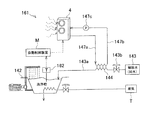
図24は第19形態に係る媒体温度調整システム191の模式図であって、媒体温度調整システム191は、空冷ヒートポンプ4の温水回路に三方弁147d(補給水温度調節弁・補給水加熱用温水熱交換量調節弁)と分岐管147eが設けられる他、第16形態と同様に成る。三方弁147dは、温水供給管147a(補給水熱交換機144の手前)に配置され、分岐管147eは、三方弁147dと温水戻り管147bの間に設置される(分岐すると補給水熱交換機144を通過せずに空冷ヒートポンプ4へ戻る)。自動制御装置Mは三方弁147dと接続されている。
[19th form]
FIG. 24 is a schematic diagram of a medium temperature adjustment system 191 according to the nineteenth embodiment. The medium temperature adjustment system 191 includes a three-way valve 147d (a supply water temperature adjustment valve / warm water heat for supply water heating) in the hot water circuit of the air cooling heat pump 4. An exchange amount adjusting valve) and a branch pipe 147e are provided, and the configuration is the same as in the sixteenth embodiment. The three-way valve 147d is arranged in the hot water supply pipe 147a (before the make-up water heat exchanger 144), and the branch pipe 147e is installed between the three-way valve 147d and the hot water return pipe 147b (if the make-up branch, the make-up water heat exchanger 144 is connected). Return to the air-cooled heat pump 4 without passing). The automatic control device M is connected to the three-way valve 147d.

媒体温度調整システム191は、第16形態と同様に動作し、自動制御装置Mは、洗浄液温度に応じ、三方弁147dを制御して温水分岐量を調節して、補給水143の加熱量を制御する。例えば、45度の洗浄液に対し、15度の補給水を55度とするため、空冷ヒートポンプ4は60度の温水を供給し、適宜分岐のうえで30度の戻り温水を受ける。   The medium temperature adjustment system 191 operates in the same manner as in the sixteenth embodiment, and the automatic control device M controls the three-way valve 147d and adjusts the amount of hot water branching according to the cleaning liquid temperature to control the heating amount of the makeup water 143. To do. For example, for the 45 degree cleaning liquid, the 15 degree makeup water is set to 55 degrees, so the air-cooled heat pump 4 supplies 60 degree hot water and receives 30 degree return hot water after branching as appropriate.

媒体温度調整システム191にあっても、媒体温度に応じて補給媒体に対する加熱量を温水分岐量の調整により変更するため、空冷ヒートポンプ4の効率的な運転を継続可能とすることができる。   Even in the medium temperature adjustment system 191, the heating amount for the replenishment medium is changed by adjusting the hot water branch amount according to the medium temperature, so that the efficient operation of the air-cooled heat pump 4 can be continued.

[第20形態]
図25は第20形態に係る媒体温度調整システム201の模式図であって、媒体温度調整システム201は、空冷ヒートポンプ4が複数台(直列に)設けられる他、第16形態と同様に成る。空冷ヒートポンプ4は、温水戻り管147b側から順に設定温度を設けて設置される。自動制御装置Mは、各空冷ヒートポンプ4を制御可能である。
[20th form]
FIG. 25 is a schematic diagram of the medium temperature adjustment system 201 according to the twentieth embodiment. The medium temperature adjustment system 201 is the same as the sixteenth embodiment except that a plurality of air-cooled heat pumps 4 are provided (in series). The air-cooled heat pump 4 is installed with a set temperature in order from the hot water return pipe 147b side. The automatic control device M can control each air-cooled heat pump 4.

例えば、6台の空冷ヒートポンプ4が設けられ、最前の空冷ヒートポンプ4の受け入れ温水設定温度30度・往き(供給)設定温度35度、次いで順に35度・40度,40度・45度,45度・50度,50度・55度,55度・60度と設定されている。最終的に60度前後に加温された温水は補給水熱交換機144に達し、15度の補給水143を55度に加温して、洗浄液を45度前後に保つ。なお、6台の内2台を30度・40度に設定する等、同じ設定温度に属するグループを作り、そのようなグループを複数設けても良いし、温度や設定幅を適宜変更しても良い。温度設定の同じグループに属する空冷ヒートポンプは、1台でも良い。   For example, six air-cooled heat pumps 4 are provided, and the receiving air water set temperature 30 degrees, forward (supply) set temperature 35 degrees, and then 35 degrees, 40 degrees, 40 degrees, 45 degrees, and 45 degrees in order.・ It is set to 50 degrees, 50 degrees and 55 degrees, 55 degrees and 60 degrees. The hot water finally heated to around 60 degrees reaches the makeup water heat exchanger 144, warms the 15 degrees makeup water 143 to 55 degrees, and keeps the cleaning liquid at around 45 degrees. It should be noted that a group belonging to the same set temperature may be created, such as setting 2 out of 6 units to 30 degrees and 40 degrees, and a plurality of such groups may be provided, or the temperature and setting range may be changed as appropriate. good. One air-cooled heat pump belonging to the same group of temperature settings may be used.

自動制御装置Mは、洗浄液温度を監視し、洗浄液温度が(目標温度より)高い場合、まず最後の(55度・60度に設定された)空冷ヒートポンプ4のみを停止し、温水供給温度を60度から55度へ下げる。又、最後の空冷ヒートポンプ4の運転停止によっても洗浄液温度が下がらない場合、最後から2番目の空冷ヒートポンプ4を停止し、以下同様とする。一方、洗浄液温度が(目標温度より)低い場合、停止された(最前のものに近い)空冷ヒートポンプ4を運転し、温水温度を上げて補給水温度を上げる。   The automatic control device M monitors the cleaning liquid temperature, and when the cleaning liquid temperature is higher than the target temperature, only the last air-cooled heat pump 4 (set to 55 degrees and 60 degrees) is stopped first, and the hot water supply temperature is set to 60. Decrease from 55 degrees to 55 degrees. If the cleaning liquid temperature does not drop even when the operation of the last air-cooled heat pump 4 is stopped, the second air-cooled heat pump 4 from the last is stopped, and so on. On the other hand, when the cleaning liquid temperature is lower (lower than the target temperature), the stopped air cooling heat pump 4 is operated (close to the previous one), the hot water temperature is raised, and the makeup water temperature is raised.

以下単独の空冷ヒートポンプ4との比較を含めた具体例につき2例説明する。   Two specific examples including a comparison with a single air-cooled heat pump 4 will be described below.

まず、洗浄槽142の洗浄液を50度に保持するために補給水143を20度から50度にする場合であるが、単独の空冷ヒートポンプ4では、加熱負荷に対応すべく、60度の温水525kcal/分(0.61kW/分)を送る(戻り温度55度)ために、0.23kW/分の電力が消費され、COPが2.6となる(外気温即ち排温風温度16度)。一方、媒体温度調整システム201のように複数のヒートポンプ4を用いる場合では、同様の加熱負荷(戻り温水温度30度・外気温16度)において、最前のものから順にCOP4.1,3.9,3.7,3.3,3.0,2.6となり、総合ではCOP3.4(消費電力0.18kW/分)となって、単独の空冷ヒートポンプ4の場合のCOP2.6(0.23kW/分)より良好となる。   First, in order to keep the cleaning liquid in the cleaning tank 142 at 50 degrees, the makeup water 143 is changed from 20 degrees to 50 degrees. In the single air-cooled heat pump 4, 60 degrees hot water 525 kcal is required to cope with the heating load. / Min (0.61 kW / min) is sent (return temperature 55 degrees), so that power of 0.23 kW / min is consumed and COP becomes 2.6 (outside air temperature, that is, exhaust air temperature 16 degrees). On the other hand, in the case where a plurality of heat pumps 4 are used as in the medium temperature adjustment system 201, COP 4.1, 3.9, COP 4.1, 3.9, and so on in order from the most recent one under the same heating load (return hot water temperature 30 ° C. and outside air temperature 16 ° C.). 3.7, 3.3, 3.0, 2.6, and overall, COP 3.4 (power consumption 0.18 kW / min), COP 2.6 (0.23 kW) in the case of a single air-cooled heat pump 4 / Min).

次に、洗浄槽142の補給水ではなく、図示しない乾燥炉のエアを加温する場合である(条件や各種値につき特開平5−31417を適宜参照)。エアは20度で導入され、空冷ヒートポンプ4の温水を入れた熱交換機(補給水熱交換機144に相当)による501kcal/分(0.58kW/分)の加熱を受け50度の温風となり、更に乾燥炉からの70度の循環温風と混合され68度の温風となり、更に他熱源としての図示しない都市ガスボイラーによる加熱(1830kcal/分・2.13kW/分)を受けて80度の温風として乾燥炉に供給される。単独の空冷ヒートポンプ4では、供給温水温度60度・戻り温水温度55度でCOP2.6・消費電力0.22kW/分となる(外気16度)。一方、媒体温度調整システム201のように複数のヒートポンプ4を用いる場合(設定温度10度減)では、供給温水温度50度・戻り温水温度20度で各COPが4.1,3.9,3.7,3.3,3.0,2.6となり、総合COP3.4・消費電力0.18kW/分となる(外気16度)。なお、乾燥炉からは70度・65m/分の排気がなされる。 Next, it is a case where the air of the drying furnace (not shown) is heated instead of the replenishing water in the cleaning tank 142 (refer to Japanese Patent Laid-Open No. 5-31417 as appropriate for conditions and various values). Air is introduced at 20 degrees, heated to 501 kcal / minute (0.58 kW / minute) by a heat exchanger (corresponding to the makeup water heat exchanger 144) filled with warm water of the air-cooled heat pump 4, and becomes warm air of 50 degrees, It is mixed with the circulating hot air of 70 degrees from the drying furnace to become a warm air of 68 degrees, and further heated by a city gas boiler (not shown) as another heat source (1830 kcal / min, 2.13 kW / min) It is supplied to the drying furnace as wind. In the single air-cooled heat pump 4, when the supply hot water temperature is 60 degrees and the return hot water temperature is 55 degrees, the COP is 2.6 and the power consumption is 0.22 kW / minute (the outside air is 16 degrees). On the other hand, when a plurality of heat pumps 4 are used as in the medium temperature adjustment system 201 (set temperature is reduced by 10 degrees), each COP is 4.1, 3.9, 3 at a supply hot water temperature of 50 degrees and a return hot water temperature of 20 degrees. 0.7, 3.3, 3.0, 2.6, resulting in a total COP of 3.4 and power consumption of 0.18 kW / min (outside air of 16 degrees). In addition, 70 degree | times * 65 m < 3 > / min exhaust is made | formed from a drying furnace.

以上の媒体温度調整システム201では、複数の空冷ヒートポンプ4を用いているため、温度設定をグループ分けすることで加温量を効率良くあるいはきめ細かに調整することができるし、全体負荷が大きい場合にも対応可能となるし、単独の場合に比べて小型のものを導入することができて、組合せによって初期コストを低減することができ、又総合しても効率を更に良好にすることが可能となって、極めて省エネルギー性の高い媒体温度調整を継続することができる。   In the medium temperature adjustment system 201 described above, since a plurality of air-cooled heat pumps 4 are used, the heating amount can be adjusted efficiently or finely by grouping the temperature settings, and when the overall load is large. It is possible to cope with the above, and it is possible to introduce a smaller one than the case of a single case, the initial cost can be reduced by combination, and the efficiency can be further improved even when combined. Thus, the medium temperature adjustment with extremely high energy saving can be continued.

[第21形態]
図26は第21形態に係る媒体温度調整システム211の模式図であって、媒体温度調整システム201は、第10形態と同様、空気圧縮機Rを備える。空気圧縮機Rには、その排温水が通る排温水管212を介して、当該排温水を冷却するクーリングタワー213が接続されており、クーリングタワー213から空気圧縮機Rへは、冷却水ポンプ214を有する処理後排温水管215が接続されている。又、排温水管212は、第1分岐管216を有しており、第1分岐管216は、第2分岐管217とも接続された三方弁218と、空冷ヒートポンプ4に隣接配置されたラジエター219を備えている。ラジエター219は、工場における送風Uを通し、暖気に変えて空冷ヒートポンプ4の空気熱交換機に吸わせる。三方弁218は、自動制御装置により制御され、分岐量を調整することでラジエター219への排温水量(熱量)を調節し、もって送風Uに付与する熱量を調整する(流量調節手段・熱量調節手段)。第2分岐管217は第1分岐管216に合流し、第1分岐管216は空冷ヒートポンプ4に接続される。なお、ラジエター219への熱量調節手段として、排温水の流量調整が可能なインバーター制御されたポンプ等を採用して良い。
[21st form]
FIG. 26 is a schematic diagram of the medium temperature adjustment system 211 according to the twenty-first embodiment, and the medium temperature adjustment system 201 includes an air compressor R as in the tenth embodiment. The air compressor R is connected to a cooling tower 213 that cools the waste water through a waste water pipe 212 through which the waste water passes, and a cooling water pump 214 is provided from the cooling tower 213 to the air compressor R. A post-treatment exhaust hot water pipe 215 is connected. Further, the exhaust hot water pipe 212 includes a first branch pipe 216, and the first branch pipe 216 is connected to the three-way valve 218 connected to the second branch pipe 217 and the radiator 219 disposed adjacent to the air-cooled heat pump 4. It has. The radiator 219 passes the blower U in the factory, changes it into warm air, and sucks it into the air heat exchanger of the air-cooled heat pump 4. The three-way valve 218 is controlled by an automatic control device, and adjusts the amount of heat discharged to the radiator 219 by adjusting the amount of branching, thereby adjusting the amount of heat applied to the blower U (flow rate adjusting means / heat amount adjustment). means). The second branch pipe 217 joins the first branch pipe 216, and the first branch pipe 216 is connected to the air-cooled heat pump 4. Note that an inverter-controlled pump or the like that can adjust the flow rate of the discharged hot water may be employed as the heat amount adjusting means for the radiator 219.

このように工場に属する排温水から温風(暖気)を生成し、工場に属する熱として空冷ヒートポンプ4の空気熱交換機に吸わせることも可能であり、直接工場で発生する暖気を空気熱交換機に当てる場合と同様に、空冷ヒートポンプ4の能力や効率を向上することができる。なお、ラジエターの代わりに、排温水(の一部)を空気熱交換機へ噴射する噴射装置を設け、排温水を空気熱交換機に当てることで、空気熱交換機が吸い込む空気を暖めても良い。又、当該噴射装置を、排温水で加熱した温水を空気熱交換機へ噴射するものとして良い。   In this way, it is possible to generate warm air (warm air) from the waste water belonging to the factory and let the air heat exchanger of the air-cooled heat pump 4 absorb the warm air generated in the factory directly to the air heat exchanger. As in the case of hitting, the capacity and efficiency of the air-cooled heat pump 4 can be improved. Instead of the radiator, an injection device that injects (a part of) the exhaust warm water to the air heat exchanger may be provided, and the air sucked by the air heat exchanger may be warmed by applying the exhaust warm water to the air heat exchanger. Moreover, the said injection apparatus is good also as what injects the warm water heated with the exhausted warm water to an air heat exchanger.

なお、各形態の変更例は、適宜他の形態にも適用可能である。又、空冷ヒートポンプには、空冷式熱回収型ヒートポンプ(冷熱と温熱を同時供給し、空気熱源で冷温熱のヒートポンプバランスを保つ機器)が含まれる。   In addition, the modified example of each form is applicable also to another form suitably. The air-cooled heat pump includes an air-cooled heat recovery type heat pump (a device that supplies cold and hot heat at the same time and maintains a heat pump balance of cold and hot with an air heat source).

1,21,31,41,51,61,71,81,91,101,111,121,131,141,151,161,171,181,191,201,211 媒体温度調整システム
2 脱脂槽
4 空冷ヒートポンプ
22 ダクト(熱案内手段)
24 工場換気ファン(熱案内手段)
32 ダクト(外気案内手段)
34 ブロワー(外気案内手段)
42 間接散水冷却装置(冷却手段)
52 自動散水装置(冷却手段)
82,142 洗浄槽
92 化成槽
147 ヒートポンプ給湯器
147c 温水循環ポンプ
A 外気
B 排温風(熱)
D 乾燥炉(熱源)
F 塗装工場(工場)
F2 部品工場(工場)
H 暖気(熱)
1, 21, 31, 41, 51, 61, 71, 81, 91, 101, 111, 121, 131, 141, 151, 161, 171, 181, 191, 201, 211 Medium temperature control system 2 Degreasing tank 4 Air cooling Heat pump 22 Duct (heat guide means)
24 Factory ventilation fan (heat guide means)
32 Duct (outside air guiding means)
34 Blower (outside air guiding means)
42 Indirect watering cooling device (cooling means)
52 Automatic watering device (cooling means)
82, 142 Cleaning tank 92 Chemical conversion tank 147 Heat pump water heater 147c Hot water circulation pump A Outside air B Waste hot air (heat)
D Drying furnace (heat source)
F painting factory (factory)
F2 parts factory (factory)
H Warm air (heat)

Claims (17)

工場で用いられる媒体を加温する加温媒体を加温する空冷ヒートポンプを備えており、
前記空冷ヒートポンプの空気熱交換機に、工場に属する熱源からの熱が当たるように、前記空冷ヒートポンプが配置されている
ことを特徴とする媒体温度調整システム。
Equipped with an air-cooled heat pump that heats the heating medium that heats the medium used in the factory,
The medium temperature adjustment system, wherein the air cooling heat pump is arranged so that heat from a heat source belonging to a factory is applied to an air heat exchanger of the air cooling heat pump.
工場で用いられる媒体を加温する加温媒体を加温する空冷ヒートポンプと、
工場に属する熱源からの熱を、前記空冷ヒートポンプの空気熱交換機に導く熱案内手段と
を有することを特徴とする媒体温度調整システム。
An air-cooled heat pump for heating a heating medium for heating a medium used in a factory;
A medium temperature adjustment system comprising: heat guide means for guiding heat from a heat source belonging to a factory to an air heat exchanger of the air-cooled heat pump.
前記工場に属する熱源からの熱は、工場に属する排温水、及び/又は 工場に属する排温水から生成した加温空気である
ことを特徴とする請求項1又は請求項2に記載の媒体温度調整システム。
The medium temperature adjustment according to claim 1 or 2, wherein the heat from the heat source belonging to the factory is exhausted warm water belonging to the factory and / or heated air generated from the exhaust warm water belonging to the factory. system.
更に、前記空冷ヒートポンプの空気熱交換機に冷気を導く冷気案内手段を備えた
ことを特徴とする請求項1ないし請求項3の何れかに記載の媒体温度調整システム。
4. The medium temperature adjustment system according to claim 1, further comprising cold air guide means for introducing cold air to an air heat exchanger of the air-cooled heat pump.
前記空冷ヒートポンプは、暖房運転及び冷房運転可能であり、
前記冷房運転時に、前記冷気案内手段により冷気を前記空気熱交換機に当て、
前記暖房運転時に、前記工場に属する熱源からの熱を前記空気熱交換機に当てる
ことを特徴とする請求項4に記載の媒体温度調整システム。
The air cooling heat pump is capable of heating operation and cooling operation,
During the cooling operation, cold air is applied to the air heat exchanger by the cold air guide means,
5. The medium temperature adjustment system according to claim 4, wherein, during the heating operation, heat from a heat source belonging to the factory is applied to the air heat exchanger.
前記熱源は、工場上部の空気である
ことを特徴とする請求項1ないし請求項5の何れかに記載の媒体温度調整システム。
6. The medium temperature adjustment system according to claim 1, wherein the heat source is air in an upper part of a factory.
更に、前記熱を冷却可能な冷却手段を備えた
ことを特徴とする請求項1ないし請求項6の何れかに記載の媒体温度調整システム。
The medium temperature adjustment system according to claim 1, further comprising a cooling unit capable of cooling the heat.
前記冷却手段は、前記空冷ヒートポンプの空気熱交換機に散水を行う自動散水装置である
ことを特徴とする請求項7に記載の媒体温度調整システム。
The medium temperature adjustment system according to claim 7, wherein the cooling unit is an automatic watering device that sprays water on an air heat exchanger of the air-cooled heat pump.
前記自動散水装置は、定期的に前記散水を行う
ことを特徴とする請求項8に記載の媒体温度調整システム。
The medium temperature adjustment system according to claim 8, wherein the automatic watering device periodically performs the watering.
前記自動散水装置は、前記空冷ヒートポンプの暖房運転時に、前記空気熱交換機に当たる空気を冷却するために前記散水を行う
ことを特徴とする請求項8又は請求項9に記載の媒体温度調整システム。
10. The medium temperature adjustment system according to claim 8, wherein the automatic watering device performs the watering to cool the air hitting the air heat exchanger during heating operation of the air-cooled heat pump.
工場で用いられる媒体を加温する加温媒体を加温するヒートポンプと、
前記媒体及び/又は加温媒体の温度に応じて、前記媒体を加温する加温媒体の熱量を調整する熱量調節手段
を備えていることを特徴とする媒体温度調整システム。
A heat pump for heating a heating medium for heating a medium used in a factory;
A medium temperature adjustment system comprising: a calorific value adjusting means for adjusting a calorific value of a heating medium for heating the medium according to a temperature of the medium and / or the heating medium.
前記熱量調節手段は、インバーター制御により前記加温媒体の流量を調整する流量調節手段である
ことを特徴とする請求項11に記載の媒体温度調整システム。
12. The medium temperature adjusting system according to claim 11, wherein the heat amount adjusting means is a flow rate adjusting means for adjusting a flow rate of the heating medium by inverter control.
前記熱量調節手段は、前記媒体の加温に用いないで戻す前記加温媒体の分岐流量を調整することで、前記媒体の加温に用いる前記加温媒体の流量を調整する流量調節手段である
ことを特徴とする請求項11又は請求項12に記載の媒体温度調整システム。
The heat quantity adjusting means is a flow rate adjusting means for adjusting a flow rate of the heating medium used for heating the medium by adjusting a branch flow rate of the heating medium to be returned without being used for heating the medium. The medium temperature adjustment system according to claim 11 or 12,
前記媒体は、補給媒体であり、
当該補給媒体を加温して補給対象に供給する管に、加温せずに前記補給媒体を補給対象へ補給する分岐管が設けられており、
前記熱量調節手段は、加温媒体の前記分岐管への流量を調整する流量調節手段である
ことを特徴とする請求項11ないし請求項13の何れかに記載の媒体温度調整システム。
The medium is a supply medium;
A pipe for heating the supply medium and supplying the supply medium to the supply object is provided with a branch pipe for supplying the supply medium to the supply object without heating.
The medium temperature adjustment system according to any one of claims 11 to 13, wherein the heat amount adjusting means is a flow rate adjusting means for adjusting a flow rate of a heating medium to the branch pipe.
前記ヒートポンプは、複数設けられており、
当該複数のヒートポンプは、互いに異なる温度設定を有するような複数のグループに分けられており、
前記熱量調節手段は、当該グループ毎に運転状態を切替えることによって、加熱媒体の熱量を調整するものである
ことを特徴とする請求項11ないし請求項14の何れかに記載の媒体温度調整システム。
A plurality of the heat pumps are provided,
The plurality of heat pumps are divided into a plurality of groups having different temperature settings,
15. The medium temperature adjusting system according to claim 11, wherein the heat amount adjusting unit adjusts the heat amount of the heating medium by switching the operation state for each group.
前記ヒートポンプは、空冷ヒートポンプである
ことを特徴とする請求項11ないし請求項15の何れかに記載の媒体温度調整システム。
The medium temperature adjustment system according to claim 11, wherein the heat pump is an air-cooled heat pump.
前記ヒートポンプは、ヒートポンプ給湯器である
ことを特徴とする請求項11ないし請求項16の何れかに記載の媒体温度調整システム。
The medium temperature adjusting system according to any one of claims 11 to 16, wherein the heat pump is a heat pump water heater.
JP2010095331A 2009-04-16 2010-04-16 Medium temperature regulating system Pending JP2010266191A (en)

Priority Applications (1)

Application Number Priority Date Filing Date Title
JP2010095331A JP2010266191A (en) 2009-04-16 2010-04-16 Medium temperature regulating system

Applications Claiming Priority (2)

Application Number Priority Date Filing Date Title
JP2009100198 2009-04-16
JP2010095331A JP2010266191A (en) 2009-04-16 2010-04-16 Medium temperature regulating system

Publications (2)

Publication Number Publication Date
JP2010266191A true JP2010266191A (en) 2010-11-25
JP2010266191A5 JP2010266191A5 (en) 2013-05-23

Family

ID=43363307

Family Applications (1)

Application Number Title Priority Date Filing Date
JP2010095331A Pending JP2010266191A (en) 2009-04-16 2010-04-16 Medium temperature regulating system

Country Status (1)

Country Link
JP (1) JP2010266191A (en)

Cited By (9)

* Cited by examiner, † Cited by third party
Publication number Priority date Publication date Assignee Title
JP2011058081A (en) * 2009-09-14 2011-03-24 Taikisha Ltd Electrodeposition coating equipment
JP2012229869A (en) * 2011-04-27 2012-11-22 Zeneral Heat Pump Kogyo Kk Industrial heat pump system
JP2012229828A (en) * 2011-04-25 2012-11-22 Zeneral Heat Pump Kogyo Kk Heat pump water heater system, and control device and control program for heat pump water heater system
WO2013047453A1 (en) * 2011-09-28 2013-04-04 東芝キヤリア株式会社 Industrial warming heat pump device
JP2013141613A (en) * 2012-01-06 2013-07-22 Toshiba Carrier Corp Industrial heating device
JP2014059068A (en) * 2012-09-14 2014-04-03 Takasago Thermal Eng Co Ltd Hot water supply system using waste heat
JP2014206315A (en) * 2013-04-12 2014-10-30 ダイダン株式会社 Component dissolving energy saving operation system
JP2020133949A (en) * 2019-02-14 2020-08-31 三浦工業株式会社 Hot water producing system
WO2023149086A1 (en) * 2022-02-03 2023-08-10 Jfeスチール株式会社 Heat recovery device, heat recovery method, and steel sheet manufacturing method

Citations (11)

* Cited by examiner, † Cited by third party
Publication number Priority date Publication date Assignee Title
JPH0242102A (en) * 1988-08-02 1990-02-13 Hitachi Ltd Method for recovering thermal energy and apparatus thereof
JP2001289532A (en) * 2000-02-02 2001-10-19 Mitsubishi Electric Corp Chiller/air-conditioner and its operation method
JP2002031376A (en) * 2000-07-19 2002-01-31 Aisin Seiki Co Ltd Air-conditioning system
JP2002286254A (en) * 2001-03-27 2002-10-03 Kimura Kohki Co Ltd Heat recovery air-cooled chiller unit
JP2005257102A (en) * 2004-03-09 2005-09-22 Fuji Electric Systems Co Ltd Heat flow control method and system in factory with industrial furnace
JP2006090620A (en) * 2004-09-24 2006-04-06 Sanki Eng Co Ltd Heat medium piping system
JP2008008594A (en) * 2006-06-30 2008-01-17 Kansai Electric Power Co Inc:The Heat pump type heat recovering device
JP2008101873A (en) * 2006-10-20 2008-05-01 Daikin Ind Ltd Auxiliary cooling device
JP2008249267A (en) * 2007-03-30 2008-10-16 Mitsubishi Electric Corp Air conditioner
JP2009014211A (en) * 2007-06-29 2009-01-22 Nepon Inc Control device and air conditioning system
JP2009042379A (en) * 2007-08-07 2009-02-26 Sanyo Electric Co Ltd Cooler for projector

Patent Citations (11)

* Cited by examiner, † Cited by third party
Publication number Priority date Publication date Assignee Title
JPH0242102A (en) * 1988-08-02 1990-02-13 Hitachi Ltd Method for recovering thermal energy and apparatus thereof
JP2001289532A (en) * 2000-02-02 2001-10-19 Mitsubishi Electric Corp Chiller/air-conditioner and its operation method
JP2002031376A (en) * 2000-07-19 2002-01-31 Aisin Seiki Co Ltd Air-conditioning system
JP2002286254A (en) * 2001-03-27 2002-10-03 Kimura Kohki Co Ltd Heat recovery air-cooled chiller unit
JP2005257102A (en) * 2004-03-09 2005-09-22 Fuji Electric Systems Co Ltd Heat flow control method and system in factory with industrial furnace
JP2006090620A (en) * 2004-09-24 2006-04-06 Sanki Eng Co Ltd Heat medium piping system
JP2008008594A (en) * 2006-06-30 2008-01-17 Kansai Electric Power Co Inc:The Heat pump type heat recovering device
JP2008101873A (en) * 2006-10-20 2008-05-01 Daikin Ind Ltd Auxiliary cooling device
JP2008249267A (en) * 2007-03-30 2008-10-16 Mitsubishi Electric Corp Air conditioner
JP2009014211A (en) * 2007-06-29 2009-01-22 Nepon Inc Control device and air conditioning system
JP2009042379A (en) * 2007-08-07 2009-02-26 Sanyo Electric Co Ltd Cooler for projector

Cited By (10)

* Cited by examiner, † Cited by third party
Publication number Priority date Publication date Assignee Title
JP2011058081A (en) * 2009-09-14 2011-03-24 Taikisha Ltd Electrodeposition coating equipment
JP2012229828A (en) * 2011-04-25 2012-11-22 Zeneral Heat Pump Kogyo Kk Heat pump water heater system, and control device and control program for heat pump water heater system
JP2012229869A (en) * 2011-04-27 2012-11-22 Zeneral Heat Pump Kogyo Kk Industrial heat pump system
WO2013047453A1 (en) * 2011-09-28 2013-04-04 東芝キヤリア株式会社 Industrial warming heat pump device
JP2013141613A (en) * 2012-01-06 2013-07-22 Toshiba Carrier Corp Industrial heating device
JP2014059068A (en) * 2012-09-14 2014-04-03 Takasago Thermal Eng Co Ltd Hot water supply system using waste heat
JP2014206315A (en) * 2013-04-12 2014-10-30 ダイダン株式会社 Component dissolving energy saving operation system
JP2020133949A (en) * 2019-02-14 2020-08-31 三浦工業株式会社 Hot water producing system
JP7379826B2 (en) 2019-02-14 2023-11-15 三浦工業株式会社 hot water production system
WO2023149086A1 (en) * 2022-02-03 2023-08-10 Jfeスチール株式会社 Heat recovery device, heat recovery method, and steel sheet manufacturing method

Similar Documents

Publication Publication Date Title
JP2010266191A (en) Medium temperature regulating system
CN107155280B (en) A kind of integration ventilating and cooling heat reclamation device
CN1295186A (en) Waste heat recovery device of engine
JP5116042B2 (en) Paint drying equipment
JP6886214B1 (en) Various energy complementary heat pump drying equipment suitable for low temperature conditions
CN105698314A (en) Evaporative cooling-mechanical refrigeration combined type energy-saving air-conditioning system for data room
JP5651366B2 (en) Air compressor exhaust heat recovery system
KR101347077B1 (en) Energy-saving air conditioner with smart damper and heat pump
CN103162362A (en) Energy-saving water-cooled air conditioner
CN102927641A (en) Well water energy-saving spinning air conditioning unit
WO2013151105A1 (en) Heat storage system and heat storage method for heat storage system
JP5367638B2 (en) Medium temperature control system
CN103322634B (en) A kind of marine engine cooling water heat utilizes device
CN209688973U (en) A kind of intermitting heating system with energy storage tank
CN204612576U (en) Cooling system
CN102878617A (en) Ceiling air-conditioning system based on container type data center
WO2012042638A1 (en) Solar heat utilization gas turbine plant
CN102853494A (en) Evaporation cooling air conditioning system capable of providing electric energy by using industrial exhaust heat
CN203163134U (en) Energy-saving water-cooling heat-pump air-conditioning device
CN110848835A (en) Energy storage and flow increasing auxiliary device for air energy cooling and heating engineering
Liebendorfer et al. Cooling the Hot Desert Wind: Turbine Inlet Cooling with Thermal Energy Storage (TES) Increases Net Power Plant Output 30%.
CN219741037U (en) Cooling unit
CN110296627B (en) Intelligent management system for waste heat recovery of air compressor and application thereof
JP2016017721A (en) Outdoor machine system
JP2016017721A5 (en)

Legal Events

Date Code Title Description
A521 Written amendment

Free format text: JAPANESE INTERMEDIATE CODE: A523

Effective date: 20130409

A621 Written request for application examination

Free format text: JAPANESE INTERMEDIATE CODE: A621

Effective date: 20130409

A871 Explanation of circumstances concerning accelerated examination

Free format text: JAPANESE INTERMEDIATE CODE: A871

Effective date: 20130409

A975 Report on accelerated examination

Free format text: JAPANESE INTERMEDIATE CODE: A971005

Effective date: 20130805

A977 Report on retrieval

Free format text: JAPANESE INTERMEDIATE CODE: A971007

Effective date: 20130807

A131 Notification of reasons for refusal

Free format text: JAPANESE INTERMEDIATE CODE: A131

Effective date: 20130813

A521 Written amendment

Free format text: JAPANESE INTERMEDIATE CODE: A523

Effective date: 20131015

A02 Decision of refusal

Free format text: JAPANESE INTERMEDIATE CODE: A02

Effective date: 20131210