JP2010252500A - Method of manufacturing yoke - Google Patents
Method of manufacturing yoke Download PDFInfo
- Publication number
- JP2010252500A JP2010252500A JP2009098558A JP2009098558A JP2010252500A JP 2010252500 A JP2010252500 A JP 2010252500A JP 2009098558 A JP2009098558 A JP 2009098558A JP 2009098558 A JP2009098558 A JP 2009098558A JP 2010252500 A JP2010252500 A JP 2010252500A
- Authority
- JP
- Japan
- Prior art keywords
- yoke
- inner diameter
- diameter
- intermediate product
- manufacturing
- Prior art date
- Legal status (The legal status is an assumption and is not a legal conclusion. Google has not performed a legal analysis and makes no representation as to the accuracy of the status listed.)
- Granted
Links
Images


Landscapes
- Shaping Metal By Deep-Drawing, Or The Like (AREA)
- Iron Core Of Rotating Electric Machines (AREA)
- Motor Or Generator Frames (AREA)
- Manufacture Of Motors, Generators (AREA)
- Permanent Field Magnets Of Synchronous Machinery (AREA)
Abstract
Description
本発明は、例えば電動モータや発電機等の回転電機に用いられる有底筒状のヨークの製造方法に関する。 The present invention relates to a method for manufacturing a bottomed cylindrical yoke used in a rotating electrical machine such as an electric motor or a generator.
パワースライドドア装置やパワーウインドドア装置等の駆動源として用いられる電動モータのヨークとしては、有底筒状のものが多く用いられている。このようなヨークでは、その開口端に径方向外側に延びるフランジ部が一体に形成され、このフランジ部によりヨークはその開口端においてギアケース等の部材に取り付けられるようになっている。また、ヨークの底部には有底筒状の軸受保持部が一体に形成され、この軸受保持部に保持された軸受によりヨークの内部に収容されるアーマチュアのアーマチュア軸の一端が回転自在に支持されるようになっている。 As a yoke of an electric motor used as a drive source for a power slide door device, a power window door device or the like, a bottomed cylindrical yoke is often used. In such a yoke, a flange portion extending radially outward is integrally formed at the opening end, and the yoke is attached to a member such as a gear case at the opening end by the flange portion. Also, a bottomed cylindrical bearing holding portion is integrally formed at the bottom of the yoke, and one end of the armature shaft of the armature housed inside the yoke is rotatably supported by the bearing held by the bearing holding portion. It has become so.
このような有底筒状のヨークは、例えば特許文献1に示されるように、円板状に形成されたブランク材等の鋼板を絞り加工(深絞り加工)することにより形成される。この場合、絞り加工は複数回行われ、各絞り加工において形成される有底筒状の中間品はその内径が徐々に小さくされて所定の最終径とされる。また、絞り加工の後には、その開口端に形成される押さえ部分がトリム加工(トリミング)され、ギアケースの形状に合わせた所定形状のフランジ部が形成される。 Such a bottomed cylindrical yoke is formed, for example, by drawing (deep drawing) a steel plate such as a blank formed in a disk shape as disclosed in Patent Document 1. In this case, the drawing process is performed a plurality of times, and the inner diameter of the bottomed cylindrical intermediate product formed in each drawing process is gradually reduced to a predetermined final diameter. In addition, after the drawing process, the pressing portion formed at the opening end is trimmed (trimmed) to form a flange portion having a predetermined shape that matches the shape of the gear case.
複数の絞り加工を経て有底筒状に形成されたヨークでは、その円筒部分やフランジ部分には当該絞り加工による圧縮応力が残留する。絞り加工直後のヨークは周方向に閉じた形状であるので、この残留応力の軸心を中心とした周方向に働く成分は全周に渡って均一に働き、ヨークの真円度に影響しないが、絞り加工の後にフランジ部や円筒部分にトリム加工が施されると、その残留応力が部分的に開放されて、ヨークの真円度が低下することになる。そして、ヨークの真円度が低下すると、ヨークの内周面へのマグネットの取り付け精度やヨークのギアケースへの取り付け精度が低下するという問題が生じることになる。 In a yoke formed into a bottomed cylindrical shape through a plurality of drawing processes, compressive stress due to the drawing process remains in the cylindrical part and the flange part. Since the yoke immediately after drawing is closed in the circumferential direction, the component acting in the circumferential direction around the axis of this residual stress works uniformly over the entire circumference, but does not affect the roundness of the yoke. When the flange portion or the cylindrical portion is trimmed after the drawing, the residual stress is partially released and the roundness of the yoke is lowered. When the roundness of the yoke is lowered, there arises a problem that the accuracy of attaching the magnet to the inner peripheral surface of the yoke and the accuracy of attaching the yoke to the gear case are lowered.
本発明の目的は、絞り加工によりヨークに残留する圧縮応力を除去して、トリム加工されても真円度が低下しないヨークを提供することにある。 An object of the present invention is to provide a yoke in which the compressive stress remaining in the yoke is removed by drawing and the roundness does not decrease even when trimmed.
本発明のヨークの製造方法は、有底筒状に形成されて回転電機に用いられるヨークの製造方法であって、鋼板を絞り加工して最終径よりも内径が大きい有底筒状の第1中間品を形成する第1絞り工程と、前記第1中間品を絞り加工して最終径よりも内径が小さい有底筒状の第2中間品を形成する第2絞り工程と、前記第2中間品の内部に工具を挿入し、該工具により前記第2中間品の内径を最終径にまで拡大する内径拡大工程とを有することを特徴とする。 The yoke manufacturing method according to the present invention is a yoke manufacturing method that is formed into a bottomed cylindrical shape and used for a rotating electrical machine, and is a first bottomed cylindrical shape having a larger inner diameter than a final diameter by drawing a steel plate. A first drawing step for forming an intermediate product, a second drawing step for drawing the first intermediate product to form a bottomed cylindrical second intermediate product having an inner diameter smaller than a final diameter, and the second intermediate product. An inside diameter expanding step of inserting a tool into the product and enlarging the inside diameter of the second intermediate product to the final diameter with the tool.
本発明のヨークの製造方法は、前記第2絞り工程の後であって前記内径拡大工程の前に、開口端にフランジ部を形成し、底部に軸受保持部を形成する整形工程が行われることを特徴とする。 In the yoke manufacturing method of the present invention, after the second drawing step and before the inner diameter expanding step, a shaping step is performed in which a flange portion is formed at the open end and a bearing holding portion is formed at the bottom portion. It is characterized by.
本発明のヨークの製造方法は、前記内径拡大工程の後に、開口端にフランジ部を形成し、底部に軸受保持部を形成する整形工程が行われることを特徴とする。 The yoke manufacturing method of the present invention is characterized in that after the inner diameter expanding step, a shaping step is performed in which a flange portion is formed at the open end and a bearing holding portion is formed at the bottom.
本発明のヨークの製造方法は、前記第2中間品の開口端から所定範囲のマグネット装着部位の内径のみを前記内径拡大工程により拡大することを特徴とする。 The yoke manufacturing method of the present invention is characterized in that only the inner diameter of the magnet mounting portion within a predetermined range from the open end of the second intermediate product is enlarged by the inner diameter enlargement step.
本発明によれば、第1絞り工程と第2絞り工程により最終径よりも内径が小さい有底筒状の中間品を形成し、この中間品の内径を内径拡大工程により最終径にまで拡大して所定の内径のヨークを形成するようにしたので、絞り工程において生じた残留圧縮応力を内径拡大工程において生じる引っ張り力により相殺することができる。これにより、ヨークの円筒部やフランジ部等がトリム加工されたときに生じる残留圧縮応力の開放による影響を低減して、ヨークの真円度を向上させることができる。また、トリム加工による真円度の低下を防止することができるので、トリム加工による真円度の変化を考慮することなく、フランジ部等の形状の設計の自由度を高めることができる。 According to the present invention, a bottomed cylindrical intermediate product having an inner diameter smaller than the final diameter is formed by the first drawing process and the second drawing process, and the inner diameter of the intermediate product is expanded to the final diameter by the inner diameter enlargement process. Since the yoke having a predetermined inner diameter is formed, the residual compressive stress generated in the drawing process can be offset by the tensile force generated in the inner diameter expanding process. As a result, it is possible to improve the roundness of the yoke by reducing the influence of the release of the residual compressive stress that occurs when the cylindrical portion, flange portion, and the like of the yoke are trimmed. Further, since it is possible to prevent the roundness from being lowered due to the trim processing, it is possible to increase the degree of freedom in designing the shape of the flange portion and the like without considering the change in the roundness due to the trim processing.
また、第2中間品の開口端から所定範囲のマグネット装着部位のみを内径拡大工程により拡大するようにしたので、ヨークの内周面に形成される段部をマグネットの位置決めとして利用することができる。 Further, since only the magnet mounting portion within a predetermined range from the opening end of the second intermediate product is enlarged by the inner diameter enlarging process, the step portion formed on the inner peripheral surface of the yoke can be used for magnet positioning. .
以下、本発明の実施の形態を図面に基づいて詳細に説明する。 Hereinafter, embodiments of the present invention will be described in detail with reference to the drawings.
図1に示すヨーク11は、車両に搭載されるパワースライドドア装置の駆動源として用いられる回転電機としての電動モータ(不図示)に使用されるものである。
A
図1、図2に示すように、このヨーク11は円筒部12と底部13とを備えた有底筒状に形成されている。円筒部12はその開口端から軸方向に向けた所定範囲に渡る大径円筒部12aと、大径円筒部12aよりも内径が小さい小径円筒部12bとが軸方向に並べて配置された構造となっており、このヨーク11の開口端の側における内径つまり大径円筒部12aの内径はDとなっている。大径円筒部12aの内側はマグネット装着部位12cとなっており、また、大径円筒部12aと小径円筒部12bとの間は段部12dとなっている。開口端からヨーク11の内部に挿入された一対のセグメント形状のマグネット14a,14bは、その軸方向端部において段部12dに突き当てられて軸方向に位置決めされた状態で大径円筒部12aの内周面つまりマグネット装着部位12cに接着等の手段により固定される。底部13には有底筒状の軸受保持部15が一体に形成されており、この軸受保持部15には軸受(不図示)が装着される。ヨーク11の内部に収容される図示しないアーマチュアは、その回転軸の一端が軸受保持部に装着される軸受に支持されて、ヨーク11の内部で回転自在に支持される。円筒部12の開口端にはフランジ部16が一体に形成されている。このフランジ部16はパワースライドドア装置の図示しないギアケースの形状に合わせた所定形状に形成されており、ヨーク11はその開口端とフランジ部16とをギアケースに突き合わせた状態で図示しないボルト等によりギアケースに固定される。
As shown in FIGS. 1 and 2, the
次に、このヨーク11の製造方法について説明する。
Next, the manufacturing method of this
このヨーク11は本発明の一実施の形態であるヨークの製造方法により製造される。このヨークの製造方法は、第1絞り工程、第2絞り工程、整形工程、内径拡大工程およびトリム工程により行われる。
The
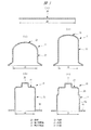
この製造方法では、ヨーク11の素材20として、図3(a)にその断面を示すように、鋼板をプレス加工により所定の直径d0の円形に打ち抜き加工して形成されたブランク材つまり円形の鋼板が用いられる。
In this manufacturing method, as a
なお、この素材20としては、図3(a)に示すようなブランク材に限らず、鋼板をレーザー切断加工等の他の加工方法により円形に形成したものを用いてもよい。また、素材20の形状は直径d0の円形に限らず、一辺の長さがd0の正方形状等、絞り加工が可能な形状であれば他の形状であってもよい。
In addition, as this
素材20が用意されると、まず、第1絞り工程が行われる。
When the
この第1絞り工程では、図示しないプレス装置により素材20が所定の絞り率で絞り加工され、図3(b)に示す第1中間品21が形成される。この第1中間品21は円筒部22と底部23とを備えた有底筒状となっており、その円筒部22の内径d1は最終径であるヨーク11の内径Dよりも大きくされている。つまり、第1絞り工程における絞り率は、第1中間品21の内径d1が最終径であるヨークの内径Dよりも大きくなるように設定されている。
In the first drawing step, the
第1絞り工程により第1中間品21が形成されると、次に、第2絞り工程が行われる。
When the first
この第2絞り工程では第1中間品21がさらに絞り加工され、図3(c)に示す第2中間品31が形成される。この第2絞り工程では、第1中間品21は、さらに細く、深く絞り加工される。これにより、第2中間品31は円筒部32と底部33とを備える第1中間品21よりも細長い有底筒状に形成されている。そして、第2中間品31の円筒部32の内径d2は、第1中間品21の内径d1や最終径であるヨーク11の内径Dよりも小さくされている。つまり、第2絞り工程における絞り率は、第2中間品31の内径d2が最終径であるヨーク11の内径Dよりも小さくなるように設定されている。このように、このヨークの製造方法では、ヨーク11を形成する第2中間品31の内径d2を、一旦、最終径であるヨーク11の内径Dよりも小さくするようにしている。
In the second drawing step, the first
第2絞り工程により第2中間品31が形成されると、次に、整形工程が行われる。
When the second
この整形工程においては、図3(d)に示すように、第2中間品31の底部33が所定の絞り加工等により整形され、当該底部33に軸受保持部35が形成される。また、第2中間品31の開口端の部分にある絞り加工時の押さえ部分が軸方向に垂直となるように整形されて開口端にフランジ部36が形成される。
In this shaping step, as shown in FIG. 3D, the bottom 33 of the second
なお、この整形工程においては、第2中間品31の内径はd2のままで変化しない。
In this shaping step, the inner diameter of the second
整形工程により軸受保持部35とフランジ部36が形成され、第2中間品31の全体の形状が整えられると、次ぎに、内径拡大工程が行われる。
When the
この内径拡大工程においては、軸受保持部35とフランジ部36が形成された第2中間品31の円筒部32が、その内径d2が最終径であるヨーク11の内径Dと同一径となるように絞り加工により拡大される。
In this inner diameter expanding step, the
図4は内径拡大工程に用いられる絞り加工装置の断面図である。 FIG. 4 is a cross-sectional view of a drawing apparatus used in the inner diameter expansion process.
この絞り加工装置41は、それぞれ板状に形成されたベース42とヘッド43とを備えている。ベース42とヘッド43はそれぞれ上下方向に向けて延びる一対のガイドポスト44に固定されて互いに上下方向に所定の間隔を空けて配置されており、加工対象となる第2中間品31は、このベース42上に配置されるようになっている。ベース42とヘッド43との間には整形ダイ45が設けられている。この整形ダイ45はガイドポスト44によりベース42とヘッド43との間で上下方向に移動自在に支持されており、また、図示しない駆動装置により駆動されて上下方向に移動することができるようになっている。整形ダイ45の軸心には、ベース42の側に向けて開口する整形用大径孔45aとヘッド43の側に向けて延びる保持用小径孔45bとが軸方向に同軸に連ねて設けられている。整形用大径孔45aの内径は保持用小径孔45bの内径よりも大きく設定されており、また、整形用大径孔45aと保持用小径孔45bとの境界部分は軸方向に対して傾斜したテーパ面45cで連ねられている。
The
ヘッド43の下面にはホルダ46が固定されている。このホルダ46は保持用小径孔45bより僅かに小径の円柱状に形成されており、保持用小径孔45bに摺動自在に挿通されている。また、ホルダ46のベース42の側を向く軸方向端面の軸心には凹部46aが設けられており、ベース42の上に配置された第2中間品31は、その軸受保持部35が凹部46aに挿入された状態で底部33においてホルダ46の軸方向端面に保持されるようになっている。
A
ベース42の下方には工具としての整形パンチ47が配置されている。この整形パンチ47は鋼材等により円柱状に形成されたパンチ本体部47aを有しており、このパンチ本体部47aの外径は最終径つまりヨーク11の内径Dと同一に設定されている。また、整形パンチ47のパンチ本体部47aの先端部分には外径が第2中間品31の内径d2と同一に設定された円柱状の突出部47bがパンチ本体部47aと同軸かつ一体に形成されており、パンチ本体部47aの突出部47bとの境界部分は湾曲面47cとなっている。ベース42の軸心には貫通孔42aが設けられており、整形パンチ47は図示しないシリンダ装置により駆動されて、この貫通孔42aからベース42の上方に向けて移動することができるようになっている。
A shaping
次に、この絞り加工装置41により行われる内径拡大工程の加工手順について、図5に基づいて説明する。
Next, a processing procedure of the inner diameter expanding process performed by the
まず、図5(a)に示すように、ベース42上の所定箇所に、第1絞り工程と第2絞り工程を経て最終径であるヨーク11の内径Dよりも小さい内径d2に形成された有底筒状の第2中間品31が開口端をベース42の貫通孔42aに合わせるように下方に向けて配置される。このとき、第2中間品31は、その底部33がホルダ46の軸方向端面に当接するとともに軸受保持部35が凹部46aに挿通されてホルダ46に支持された状態とされる。
First, as shown in FIG. 5A, an inner diameter d2 is formed at a predetermined position on the base 42 through the first drawing process and the second drawing process so that the inner diameter d2 is smaller than the inner diameter D of the
次に、この状態から、図示しない駆動装置により整形ダイ45が図中下方に向けて駆動される。整形ダイ45が下方に駆動されると、図5(b)に示すように、整形ダイ45の下面とベース42の上面との間にフランジ部36が挟み込まれて第2中間品31がベース42に保持される。また、整形ダイ45がホルダ46に対して移動することにより、第2中間品31の底部33の側から所定範囲における円筒部32の外周部分が整形ダイ45の保持用小径孔45bの内周面に保持される。そして、この状態においては、第2中間品31の円筒部32の開口端から所定範囲における外周面は、整形用大径孔45aの内周面に対して所定の隙間を空けて対向している。
Next, from this state, the shaping die 45 is driven downward in the figure by a driving device (not shown). When the shaping die 45 is driven downward, the
次に、この状態から、図示しないシリンダ装置により整形パンチ47が上方つまり第2中間品31の内部に向けて駆動される。そして、整形パンチ47はベース42の貫通孔42aからベース42の上方に突出し、図5(c)に示すように、第2中間品31の円筒部32の内部に挿入される。このとき、整形パンチ47のパンチ本体部47aは第2中間品31の円筒部32の開口端から所定範囲つまり整形ダイ45の整形用大径孔45aに対応した位置にまで突出し、突出部47bは保持用小径孔45bに対応した部分に突出する。
Next, from this state, the shaping
ここで、整形パンチ47のパンチ本体部47aの外径はヨーク11の内径Dと同一つまり第2中間品31の内径d2よりも大径に形成されているので、整形パンチ47のパンチ本体部47aが内部に挿入されると、第2中間品31の円筒部32の開口端から所定範囲の部分つまりその外周面が整形用大径孔45aの内周面に対向する部分は整形パンチ47のパンチ本体部47aにより径方向外側に押し広げられ、その外周面が整形用大径孔45aの内周面に当接する。これにより、第2中間品31の円筒部32の開口端から所定範囲の部分つまりマグネット装着部位12cに対応する部分は、整形パンチ47と整形用大径孔45aとにより挟み込まれて絞られ、その内径が拡大される方向に塑性変形されて最終径つまりヨーク11の内径Dと同一径にまで拡大される。
Here, since the outer diameter of the
なお、第2中間品31の内径が拡大された部分がヨーク11の大径円筒部12aとなり、その内側がマグネット装着部位12cとなる。
In addition, the part by which the internal diameter of the 2nd
一方、第2中間品31の円筒部32の底部33の側から所定範囲の部分つまり円筒部32の外周面が保持用小径孔45bの内周面に保持された部分は、その内側に整形パンチ47の突出部47bが挿入された状態となり、保持用小径孔45bの内周面と突出部47bの外周面の間に挟み込まれて保持される。これにより、第2中間品31の円筒部32の底部33から所定範囲の部分は、その内径が第2中間品31の内径d2から変化せず、ヨーク11の大径円筒部12aよりも小径の小径円筒部12bとなる。また、第2中間品31の円筒部32の一部が、整形ダイ45のテーパ面45cと整形パンチ47の湾曲面47cとの間に挟み込まれることにより、ヨーク11の円筒部12には軸方向に対してテーパ状に傾斜した段部12dが形成されることになる。
On the other hand, a portion within a predetermined range from the bottom 33 side of the
このように、本発明のヨークの製造方法では、第1絞り工程と第2絞り工程により最終径であるヨーク11の内径Dよりも内径が小さい有底筒状の第2中間品31を形成し、この第2中間品31の内径d2を内径拡大工程により最終径と同一の内径Dにまで拡大して所定の内径Dのヨーク11を形成するようにしている。これにより、第1絞り工程と第2絞り工程とで行われる絞り工程により第2中間品31の内部に残留する周方向の圧縮応力を、内径拡大工程において生じる周方向の引っ張り力により相殺して低減させることができる。
Thus, in the yoke manufacturing method of the present invention, the bottomed cylindrical second
なお、本実施の形態においては、素材20の直径d0=202mm、第1中間品21の内径d1=108mm、第2中間品31の内径d2=81mm、最終径であるヨーク11の内径D=82.33mmとされており、第1絞り工程の絞り率は0.53、第2絞り工程の絞り率は0.75、内径拡大工程の絞り率(拡大率)は1.02となっている。
In this embodiment, the diameter d0 of the
内径拡大工程の次は、第2中間品31のフランジ部36を所定の形状のフランジ部16に形成するトリム工程が行われる。
After the inner diameter expanding step, a trim step for forming the
トリム工程においては、図6(a)に示すように、素材20に合わせた円形となっているフランジ部16が、図6(b)に示すように、ブランク型等を用いたプレス加工により所定の形状に打ち抜かれる。
In the trimming process, as shown in FIG. 6 (a), the
このとき、本発明の製造方法により製造されたヨーク11では、第1絞り工程と第2絞り工程とで行われる絞り加工により第2中間品31の内部に生じる周方向に向く圧縮残留応力は、内径拡大工程によりその内径が拡大するように塑性変形を受けることにより、当該塑性変形による周方向の引っ張り力により相殺されて低減されている。したがって、円周方向に向けて不均一な形状にフランジ部16をトリム加工しても、その圧縮残留応力による真円度への影響は小さくなり、このヨーク11の円筒部12の真円度を向上させることができる。
At this time, in the
このように、本発明のヨークの製造方法では、第1絞り工程と第2絞り工程により最終径であるヨーク11の内径Dよりも内径が小さい有底筒状の第2中間品31を形成し、この第2中間品31の内径d2を内径拡大工程により最終径にまで拡大して所定の内径Dのヨーク11を形成するようにしている。したがって、各絞り工程における絞り加工により生じた周方向に向く残留圧縮応力を内径拡大工程において周方向に生じる引っ張り力により相殺して、ヨーク11の円筒部12やフランジ部16等がトリム加工されたときに生じる残留圧縮応力の開放による真円度への影響を低減することができる。これにより、各絞り工程における絞り加工によりヨーク11に残留する圧縮応力を除去して、トリム加工されても真円度が低下しないヨーク11を提供することができる。
Thus, in the yoke manufacturing method of the present invention, the bottomed cylindrical second
また、トリム加工による真円度の低下を防止することができるので、トリム加工による真円度の変化を考慮することなく、フランジ部16等の形状の設計の自由度を高めることができる。
Further, since it is possible to prevent the roundness from being lowered due to the trim processing, it is possible to increase the degree of freedom in designing the shape of the
また、本発明のヨークの製造方法では、第2中間品31の開口端から所定範囲のマグネット装着部位12cに対応する部分の内径のみを内径拡大工程により拡大するようにしたので、ヨーク11の内周面に段部12dが形成されることになる。そして、この段部12dをマグネット14a,14bのヨーク11内における軸方向への位置決めとして利用することにより、他の部材や治具等を用いることなく、マグネット14a,14bの位置決め精度を高めることができる。
Further, in the yoke manufacturing method of the present invention, only the inner diameter of the portion corresponding to the
図7は本発明の他の実施の形態であるヨークの製造方法により製造されたヨークの横断面図であり、図8(a)〜(e)はそれぞれ図7に示すヨークの製造手順を示す説明図である。 FIG. 7 is a cross-sectional view of a yoke manufactured by a yoke manufacturing method according to another embodiment of the present invention, and FIGS. 8A to 8E respectively show the manufacturing procedure of the yoke shown in FIG. It is explanatory drawing.
図3に示すヨークの製造方法では、第2絞り工程の後であって内径拡大工程の前に整形工程を行うことにより、大径円筒部12aと小径円筒部12bとを備えた段付き形状のヨーク11を形成するようにしている。
In the yoke manufacturing method shown in FIG. 3, a stepped shape having a large diameter
これに対して、図8に示すヨークの製造方法では、第2絞り工程の後であって整形工程の前に内径拡大工程を行うようにしている。つまり、内径拡大工程により、軸受保持部15が設けられず、また、全体形状が整形されていないヨーク11が形成され、その後、整形工程を行うようにしている。また、この実施の形態においては、内径拡大工程においては、第2中間品31の円筒部32の全体の内径を拡大させるようにしており、内径拡大工程を終えた後は、整形工程においてヨーク11の内径は変化しない。これにより、ヨーク11は、図7に示すように、図2に示すような段部12dを持たない内径が一様な円筒部12を備えた有底筒状に形成される。このように、内径拡大工程は、整形工程の前後に拘わらず、第1絞り工程と第2絞り工程とを経た後であれば、いずれのタイミングで行われてもよい。
On the other hand, in the yoke manufacturing method shown in FIG. 8, the inner diameter expanding step is performed after the second drawing step and before the shaping step. That is, the
なお、図7、図8においては、前述した部材に対応する部材には同一の符号を付してある。 In FIGS. 7 and 8, members corresponding to those described above are denoted by the same reference numerals.
本発明は前記実施の形態に限定されるものではなく、その要旨を逸脱しない範囲で種々変更可能であることはいうまでもない。例えば、前記実施の形態においては、第1絞り工程、第2絞り工程および内径拡大工程の他に、整形工程とトリム工程を行うようにしているが、これに限らず、整形工程とトリム工程は任意に行えばよく、不要であれば行わなくてもよい。 It goes without saying that the present invention is not limited to the above-described embodiment, and various modifications can be made without departing from the scope of the invention. For example, in the embodiment described above, the shaping process and the trimming process are performed in addition to the first drawing process, the second drawing process, and the inner diameter expanding process. It may be performed arbitrarily, and may be omitted if unnecessary.
また、前記実施の形態においては、第1絞り工程と第2絞り工程の2回の絞り工程で素材20を第2中間品31にまで加工しているが、これに限らず、第1絞り工程の前、あるいは第1絞り工程と第2絞り工程との間に、さらに別の絞り工程を追加して、2回以上の絞り加工を経て第2中間品31を形成するようにしてもよい。
Moreover, in the said embodiment, although the
さらに、前記実施の形態においては、パワースライドドア装置の駆動源として用いられる電動モータのヨーク11に本発明を適用したが、これに限らず、他の用途に用いられる電動モータや発電機などの他の回転電機のヨークに本発明を適用するようにしてもよい。
Furthermore, in the said embodiment, although this invention was applied to the
さらに、前記実施の形態においては、トリム加工はフランジ部のみを加工するようにしているが、これに限らず、ヨーク11の円筒部12の一部に軸方向に延びる切り欠きを設ける加工など、円筒部12に加工するものであってもよい。
Furthermore, in the above-described embodiment, trimming is performed only on the flange portion. However, the present invention is not limited to this, and processing such as providing a notch extending in the axial direction in a part of the
11 ヨーク
12 円筒部
12a 大径円筒部
12b 小径円筒部
12c マグネット装着部位
12d 段部
13 底部
14a,14b マグネット
15 軸受保持部
16 フランジ部
20 素材(鋼板)
21 第1中間品
22 円筒部
23 底部
31 第2中間品
32 円筒部
33 底部
35 軸受保持部
36 フランジ部
41 絞り加工装置
42 ベース
42a 貫通孔
43 ヘッド
44 ガイドポスト
45 整形ダイ
45a 整形用大径孔
45b 保持用小径孔
45c テーパ面
46 ホルダ
46a 凹部
47 整形パンチ(工具)
47a パンチ本体部
47b 突出部
47c 湾曲面
D 内径
d0 直径
d1,d2 内径
11
21 First
Claims (4)
鋼板を絞り加工して最終径よりも内径が大きい有底筒状の第1中間品を形成する第1絞り工程と、
前記第1中間品を絞り加工して最終径よりも内径が小さい有底筒状の第2中間品を形成する第2絞り工程と、
前記第2中間品の内部に工具を挿入し、該工具により前記第2中間品の内径を最終径にまで拡大する内径拡大工程とを有することを特徴とするヨークの製造方法。 A method of manufacturing a yoke that is formed into a bottomed cylindrical shape and is used in a rotating electric machine,
A first drawing step of drawing a steel plate to form a bottomed cylindrical first intermediate product having a larger inner diameter than the final diameter;
A second drawing step of drawing the first intermediate product to form a bottomed cylindrical second intermediate product having an inner diameter smaller than the final diameter;
A method of manufacturing a yoke, comprising: inserting a tool into the second intermediate product, and expanding the inner diameter of the second intermediate product to the final diameter with the tool.
Priority Applications (1)
| Application Number | Priority Date | Filing Date | Title |
|---|---|---|---|
| JP2009098558A JP5317808B2 (en) | 2009-04-15 | 2009-04-15 | Yoke manufacturing method |
Applications Claiming Priority (1)
| Application Number | Priority Date | Filing Date | Title |
|---|---|---|---|
| JP2009098558A JP5317808B2 (en) | 2009-04-15 | 2009-04-15 | Yoke manufacturing method |
Publications (2)
| Publication Number | Publication Date |
|---|---|
| JP2010252500A true JP2010252500A (en) | 2010-11-04 |
| JP5317808B2 JP5317808B2 (en) | 2013-10-16 |
Family
ID=43314196
Family Applications (1)
| Application Number | Title | Priority Date | Filing Date |
|---|---|---|---|
| JP2009098558A Expired - Fee Related JP5317808B2 (en) | 2009-04-15 | 2009-04-15 | Yoke manufacturing method |
Country Status (1)
| Country | Link |
|---|---|
| JP (1) | JP5317808B2 (en) |
Citations (16)
| Publication number | Priority date | Publication date | Assignee | Title |
|---|---|---|---|---|
| JPS5795165A (en) * | 1980-12-03 | 1982-06-12 | Kokusan Denki Co Ltd | Molding of cover for rotary electric machine |
| JPS6231351A (en) * | 1985-07-29 | 1987-02-10 | Mitsuba Electric Mfg Co Ltd | Manufacture of yoke |
| JPH0549193A (en) * | 1991-08-14 | 1993-02-26 | Hitachi Ltd | Fabrication of miniature motor and yoke having improved assembling structure of end cover and yoke |
| JPH0550967U (en) * | 1991-12-09 | 1993-07-02 | 株式会社三ツ葉電機製作所 | Rotating electric machine yoke |
| JPH09331657A (en) * | 1996-06-10 | 1997-12-22 | Denso Corp | Manufacture of yoke of magnet-type motor |
| JPH10225044A (en) * | 1997-02-06 | 1998-08-21 | Asmo Co Ltd | Dynamo-electric machine and its manufacture |
| JP2000005827A (en) * | 1998-06-24 | 2000-01-11 | Asmo Co Ltd | Die for thickness increase draw processing |
| JP2001286105A (en) * | 2000-03-30 | 2001-10-12 | Asmo Co Ltd | Yoke of rotating electric machine and manufacturing method for the yoke |
| JP2002160021A (en) * | 2000-09-13 | 2002-06-04 | Asmo Co Ltd | Method for manufacturing yoke |
| JP2002186225A (en) * | 2000-12-13 | 2002-06-28 | Asmo Co Ltd | Yoke of rotary electric machine and method of manufacturing the same |
| JP2002325389A (en) * | 2001-04-27 | 2002-11-08 | Asmo Co Ltd | Yoke of dynamo-electric machine, and manufacturing method therefor |
| JP2003061317A (en) * | 2001-06-08 | 2003-02-28 | Asmo Co Ltd | Yoke of electric rotating machine and its producing method |
| JP2003284265A (en) * | 2002-03-26 | 2003-10-03 | Asmo Co Ltd | Yoke for rotary-electric machine and manufacturing method therefor |
| JP2006326671A (en) * | 2005-05-30 | 2006-12-07 | Asmo Co Ltd | Method for manufacturing flanged and bottomed cylindrical body, flanged and bottomed cylindrical body, and yoke for dynamo-electric machine |
| JP2007068261A (en) * | 2005-08-29 | 2007-03-15 | Mitsuba Corp | Yoke for motor |
| JP2009050912A (en) * | 2007-08-29 | 2009-03-12 | Asmo Co Ltd | Cylindrical body manufacturing method and drawn cylindrical body |
-
2009
- 2009-04-15 JP JP2009098558A patent/JP5317808B2/en not_active Expired - Fee Related
Patent Citations (16)
| Publication number | Priority date | Publication date | Assignee | Title |
|---|---|---|---|---|
| JPS5795165A (en) * | 1980-12-03 | 1982-06-12 | Kokusan Denki Co Ltd | Molding of cover for rotary electric machine |
| JPS6231351A (en) * | 1985-07-29 | 1987-02-10 | Mitsuba Electric Mfg Co Ltd | Manufacture of yoke |
| JPH0549193A (en) * | 1991-08-14 | 1993-02-26 | Hitachi Ltd | Fabrication of miniature motor and yoke having improved assembling structure of end cover and yoke |
| JPH0550967U (en) * | 1991-12-09 | 1993-07-02 | 株式会社三ツ葉電機製作所 | Rotating electric machine yoke |
| JPH09331657A (en) * | 1996-06-10 | 1997-12-22 | Denso Corp | Manufacture of yoke of magnet-type motor |
| JPH10225044A (en) * | 1997-02-06 | 1998-08-21 | Asmo Co Ltd | Dynamo-electric machine and its manufacture |
| JP2000005827A (en) * | 1998-06-24 | 2000-01-11 | Asmo Co Ltd | Die for thickness increase draw processing |
| JP2001286105A (en) * | 2000-03-30 | 2001-10-12 | Asmo Co Ltd | Yoke of rotating electric machine and manufacturing method for the yoke |
| JP2002160021A (en) * | 2000-09-13 | 2002-06-04 | Asmo Co Ltd | Method for manufacturing yoke |
| JP2002186225A (en) * | 2000-12-13 | 2002-06-28 | Asmo Co Ltd | Yoke of rotary electric machine and method of manufacturing the same |
| JP2002325389A (en) * | 2001-04-27 | 2002-11-08 | Asmo Co Ltd | Yoke of dynamo-electric machine, and manufacturing method therefor |
| JP2003061317A (en) * | 2001-06-08 | 2003-02-28 | Asmo Co Ltd | Yoke of electric rotating machine and its producing method |
| JP2003284265A (en) * | 2002-03-26 | 2003-10-03 | Asmo Co Ltd | Yoke for rotary-electric machine and manufacturing method therefor |
| JP2006326671A (en) * | 2005-05-30 | 2006-12-07 | Asmo Co Ltd | Method for manufacturing flanged and bottomed cylindrical body, flanged and bottomed cylindrical body, and yoke for dynamo-electric machine |
| JP2007068261A (en) * | 2005-08-29 | 2007-03-15 | Mitsuba Corp | Yoke for motor |
| JP2009050912A (en) * | 2007-08-29 | 2009-03-12 | Asmo Co Ltd | Cylindrical body manufacturing method and drawn cylindrical body |
Also Published As
| Publication number | Publication date |
|---|---|
| JP5317808B2 (en) | 2013-10-16 |
Similar Documents
| Publication | Publication Date | Title |
|---|---|---|
| US9302317B2 (en) | Method for manufacturing hollow engine valve | |
| JP5734354B2 (en) | Tool clamping device | |
| JP7254520B2 (en) | Spindle nut, screw transmission, and method of manufacturing spindle nut | |
| JP5626061B2 (en) | Tooth profile part manufacturing method and tooth profile part manufacturing apparatus | |
| JPWO2006126622A1 (en) | Drilling method and drilling device | |
| US9315117B2 (en) | Method for producing a spindle drive of an adjustment device of a motor vehicle seat | |
| JP2010075931A (en) | Method of press-forming cylindrical metallic part having flange | |
| JP5397396B2 (en) | Manufacturing method of rotor core of rotating electrical machine | |
| US8136380B2 (en) | Spline member manufacturing apparatus and manufacturing method | |
| JP5317808B2 (en) | Yoke manufacturing method | |
| US11759846B2 (en) | Method for producing a polygonal shaft | |
| JP2006326671A (en) | Method for manufacturing flanged and bottomed cylindrical body, flanged and bottomed cylindrical body, and yoke for dynamo-electric machine | |
| JP2015516303A (en) | Apparatus and method for producing thick-walled hollow wheels with internal gear teeth | |
| JP4217691B2 (en) | Manufacturing method for cylindrical parts | |
| JP2010188414A (en) | Method for manufacturing metallic ring-shaped component and plastic working apparatus for metallic component | |
| JP2007283404A (en) | Assembly caulking metallic plate-like body and column-like body, method and apparatus for manufacturing it | |
| JP5021333B2 (en) | Shaft manufacturing method and manufacturing apparatus thereof | |
| JPH1071448A (en) | Bolt forming method and bolt | |
| JP3642509B2 (en) | Tooth profile sizing mold | |
| KR20140068621A (en) | Forming metallic pattern for pipe | |
| JP5643682B2 (en) | Manufacturing method of rotor hub | |
| JP2011104607A (en) | Integral rotor for permanent-magnet generator and method of manufacturing the same from steel sheet by cold forging forming | |
| JP2007260720A (en) | Method for forming hole having part for preventing fall-off | |
| JP4597762B2 (en) | Upsetting method and upsetting apparatus | |
| CN117157158A (en) | Device and method for continuously producing an at least partially hollow shaft with a variable inner and/or outer diameter |
Legal Events
| Date | Code | Title | Description |
|---|---|---|---|
| A621 | Written request for application examination |
Free format text: JAPANESE INTERMEDIATE CODE: A621 Effective date: 20120329 |
|
| TRDD | Decision of grant or rejection written | ||
| A977 | Report on retrieval |
Free format text: JAPANESE INTERMEDIATE CODE: A971007 Effective date: 20130628 |
|
| A01 | Written decision to grant a patent or to grant a registration (utility model) |
Free format text: JAPANESE INTERMEDIATE CODE: A01 Effective date: 20130702 |
|
| A61 | First payment of annual fees (during grant procedure) |
Free format text: JAPANESE INTERMEDIATE CODE: A61 Effective date: 20130709 |
|
| R150 | Certificate of patent or registration of utility model |
Ref document number: 5317808 Country of ref document: JP Free format text: JAPANESE INTERMEDIATE CODE: R150 Free format text: JAPANESE INTERMEDIATE CODE: R150 |
|
| LAPS | Cancellation because of no payment of annual fees |