JP2010249155A - Conversion joint for culvert pipe, branch joint, flexible pipe, and culvert pipe using branch joint and flexible pipe - Google Patents
Conversion joint for culvert pipe, branch joint, flexible pipe, and culvert pipe using branch joint and flexible pipe Download PDFInfo
- Publication number
- JP2010249155A JP2010249155A JP2009096069A JP2009096069A JP2010249155A JP 2010249155 A JP2010249155 A JP 2010249155A JP 2009096069 A JP2009096069 A JP 2009096069A JP 2009096069 A JP2009096069 A JP 2009096069A JP 2010249155 A JP2010249155 A JP 2010249155A
- Authority
- JP
- Japan
- Prior art keywords
- pipe
- joint
- perforated sheet
- culvert
- female
- Prior art date
- Legal status (The legal status is an assumption and is not a legal conclusion. Google has not performed a legal analysis and makes no representation as to the accuracy of the status listed.)
- Pending
Links
Images


Abstract
Description
本発明は、暗渠パイプ用の変換継手、分岐継手および可撓性管ならびにこれらを用いた暗渠パイプに関する。 The present invention relates to a conversion joint, a branch joint and a flexible pipe for a culvert pipe and a culvert pipe using these.
水田、畑などの土壌中の余剰水を排水して、土壌の水分をコントロールする方法として、土壌中に暗渠パイプを敷設することが行われている。暗渠パイプには、特許文献1に記載されているように、多数の孔が形成された樹脂製の有孔シートをパイプ状に成形した有孔シートパイプが使用されることが多い。 As a method of draining surplus water in soil such as paddy fields and fields and controlling the moisture of the soil, a culvert pipe is laid in the soil. As described in Patent Document 1, a perforated sheet pipe in which a resin-made perforated sheet formed with a large number of holes is formed into a pipe shape is often used as the underdrain pipe.
有孔シートパイプの敷設方法としては、有孔シートをパイプ成形器でパイプ状に成形しつつ、これをブルドーザで地中数十cmの深さにおいて牽引して、100m程度の長さに敷設する方法が一般的である。例えば、図7に概略的に示すように、こうして敷設される有孔シートパイプ10、10’は、通常、数m程度の間隔で互いに平行に複数本(この例では7本)配置される。
As a method for laying a perforated sheet pipe, a perforated sheet is formed into a pipe shape with a pipe molding machine, and pulled to a depth of several tens of centimeters with a bulldozer and laid to a length of about 100 m. The method is common. For example, as schematically shown in FIG. 7, the
このように複数本の有孔シートパイプ10、10’が敷設される場合、図示例のように、一方の端部に通気部20が形成され、他方の端部に排水部30が形成された有孔シートパイプ10と、これらが形成されていない有孔シートパイプ10’とが例えば交互に配置されることがある。そして、通気部20および排水部30が形成されていない有孔シートパイプ10’の両端と、この有孔シートパイプ10’に隣接する両側の有孔シートパイプ10の通気部20および排水部30とは、図8に通気部20を拡大して例示するように、複数のT字継手12、12’および連通管18により接続されている。
When a plurality of perforated
通気部20および排水部30は、具体的には、図9に示すように構成されている。
すなわち、有孔シートパイプ10の一方の端部10aに、塩化ビニル樹脂製の接続管11aが接続された後、直列に連結された2つのT字継手12を経て、再度塩化ビニル樹脂製の接続管11bが接続され、ついで、可撓性のあるコルゲート管13が接続され、さらに直管からなる塩化ビニル樹脂製の立上がり管14が接続される。そして、コルゲート管13を適切な角度で上方に曲げて、立上がり管14の末端14aが土壌Sから大気中に突出するようにして、大気と連通する通気部20が形成されている。立上がり管14の末端14aには、通気孔付キャップ15が嵌められる。
一方、有孔シートパイプ10の他方の端部10bには、塩化ビニル樹脂製の接続管11aが接続された後、直列に連結された2つのT字継手12を経て、再度塩化ビニル樹脂製の接続管11bが接続され、ついで、コルゲート管13が接続され、さらに直管からなる塩化ビニル樹脂製の排水管16が接続される。そして、コルゲート管13を適切な角度で下方に曲げて、排水管16の末端16aが排水溝Dの側面から大気中に突出するようにして、有孔シートパイプ10内に集水された余剰水が排水溝Dに流れ込む排水部30が形成されている。排水管16の末端16aには、水閘17が嵌められる。
The
That is, after the
On the other hand, after the connecting
この例のように、通気部20および排水部30が形成された有孔シートパイプ10と、これらが形成されていない有孔シートパイプ10’とを組み合わせて配置し、連通管18により有孔シートパイプ10’の両端が通気部20および排水部30と連通するように暗渠パイプを構成すると、通気部20および排水部30が形成されていない有孔シートパイプ10’においても、通気を保ち、かつ、集水された余剰水を排水溝Dに排水することができる。このような構成は、全ての有孔シートパイプ10、10’に通気部20および排水部30をそれぞれ形成する構成に比べて、これらの形成コストを抑制でき、工期も短縮できるというメリットがある。
As in this example, the
しかしながら、このような従来の暗渠パイプでは、通気部20における各管同士の接続部分(有孔シートパイプ10の端部10aと接続管11aとの接続部分、接続管11bとコルゲート管13との接続部分、コルゲート管13と立ち上がり管14との接続部分)や、排水部30における各管同士の接続部分(有孔シートパイプ10の端部10bと接続管11aとの接続部分、接続管11bとコルゲート管13との接続部分、コルゲート管13と排水管16との接続部分)は、いずれも単に各管の端部同士を嵌合させただけで構成されていた。そのため、有孔シートパイプ10、10’に集水された余剰水がこれらの接続部分から土壌S中に漏れ出てしまうという水漏れの問題があった。
さらに、暗渠パイプには、土砂、枯葉が入り込みやすいため、通常、洗浄ホースを通気部20の立上がり管14の末端14aから挿入して、土砂、枯葉などを排水部30から排出させる洗浄作業が定期的に実施されているが、このような洗浄作業時に、通気部20や排水部30で上述のような水漏れが起こると、効率的に土砂、枯葉を排水部30から排出させることができず、十分な洗浄効果が得られなかった。
However, in such a conventional culvert pipe, the connection part of each pipe | tube in the ventilation part 20 (The connection part of the
Furthermore, since dirt and dead leaves are likely to enter the culvert pipe, a cleaning operation is usually performed in which a washing hose is inserted from the
また、このような従来の暗渠パイプでは、通気部20および排水部30が形成されていない有孔シートパイプ10’の両端を通気部20および排水部30に連通させる場合には、図8に示したように、直列に連結させた2つのT字継手12を使用していたため、接続部品数がかさむという問題もあった。
Further, in such a conventional underdrain pipe, when both ends of the
本発明は上記事情に鑑みてなされたもので、暗渠パイプの通気部や排水部の接続部分における水漏れを防止し、余剰水の排水や暗渠パイプの洗浄を効率的に行うことができ、使用される接続部品数も抑制できる暗渠パイプと、これに使用される暗渠パイプ用の変換継手、分岐継手および可撓性管の提供を課題とする。 The present invention has been made in view of the above circumstances, can prevent water leakage at the connecting portion of the vent portion and drainage portion of the underdrain pipe, can efficiently drain the excess water and wash the underdrain pipe, and can be used. It is an object of the present invention to provide a culvert pipe that can also suppress the number of connected parts, and a conversion joint, a branch joint, and a flexible pipe for the culvert pipe used therefor.
本発明の変換継手は、土壌中の余剰水を排水する暗渠パイプに使用される変換継手であって、有孔シートパイプが液密に挿入される雌型の小径接続口と、前記有孔シートパイプよりも大径の樹脂製の直管が液密に挿入される雌型の大径接続口とが形成されたことを特徴とする。
前記小径接続口には、内面取り加工が施されていることが好ましい。
本発明の分岐継手は、土壌中の余剰水を排水する暗渠パイプに使用される分岐継手であって、樹脂製の直管が液密に挿入される雌型の接続口が4つ形成され、かつ、これらの接続口が十字に形成されたことを特徴とする。
本発明の可撓性管は、土壌中の余剰水を排水する暗渠パイプに使用される可撓性管であって、可撓性管本体と、該可撓性管本体の少なくとも一端に接合され、該可撓性管本体と樹脂製の直管とを液密に接続する継手とを備えていることを特徴とする。
本発明の暗渠パイプは、土壌中の余剰水を排水する暗渠パイプであって、
有孔シートがパイプ状に成形された有孔シートパイプと、
複数の樹脂製の直管と、
前記有孔シートパイプが液密に挿入される雌型の小径接続口と、前記有孔シートパイプよりも大径の樹脂製の直管が液密に挿入される雌型の大径接続口とが形成された変換継手と、
樹脂製の直管が液密に挿入される雌型の接続口が4つ形成され、かつ、これらの接続口が十字に形成された分岐継手と、
可撓性管本体と、該可撓性管本体の少なくとも一端に接合され、該可撓性管本体と樹脂製の直管とを液密に接続する継手とを備えた可撓性管、を具備して構成されたことを特徴とする暗渠パイプ。
The conversion joint of the present invention is a conversion joint used for a culvert pipe that drains surplus water in soil, and is a female-type small-diameter connection port into which a perforated sheet pipe is inserted in a liquid-tight manner, and the perforated sheet. A female large-diameter connection port into which a straight resin pipe having a diameter larger than that of the pipe is liquid-tightly inserted is formed.
The small-diameter connection port is preferably subjected to inner surface machining.
The branch joint of the present invention is a branch joint used for a culvert pipe that drains surplus water in the soil, and four female connection ports into which a resin straight pipe is inserted in a liquid-tight manner are formed, In addition, these connection ports are formed in a cross shape.
The flexible tube of the present invention is a flexible tube used for a culvert pipe that drains surplus water in soil, and is joined to at least one end of the flexible tube main body and the flexible tube main body. The flexible pipe main body and a resin straight pipe are provided with a joint for liquid-tight connection.
The underdrain pipe of the present invention is an underdrain pipe that drains surplus water in the soil,
A perforated sheet pipe in which a perforated sheet is formed into a pipe shape;
A plurality of resin straight pipes;
A female-type small-diameter connection port into which the perforated sheet pipe is inserted in a liquid-tight manner, and a female-type large-diameter connection port into which a resin straight pipe having a larger diameter than the perforated sheet pipe is inserted in a liquid-tight manner A conversion joint formed with
A branch joint in which four female connection ports into which resin straight pipes are inserted in a liquid-tight manner are formed, and these connection ports are formed in a cross shape;
A flexible tube comprising: a flexible tube main body; and a joint that is bonded to at least one end of the flexible tube main body and fluidly connects the flexible tube main body and a resin straight pipe. A culvert pipe characterized by comprising.
本発明によれば、暗渠パイプの通気部や排水部の接続部分における水漏れを防止し、余剰水の排水や暗渠パイプの洗浄を効率的に行うことができ、使用される接続部品数も抑制できる暗渠パイプと、これに使用される暗渠パイプ用の変換継手、分岐継手および可撓性管を提供できる。 According to the present invention, it is possible to prevent water leakage at the connection portion of the vent of the underdrain pipe and the drainage portion, to efficiently drain the excess water and to wash the underdrain pipe, and to suppress the number of connecting parts used. Can be provided, and conversion joints, branch joints and flexible pipes for the culvert pipes used therefor can be provided.
以下、本発明について詳細に説明する。
本発明の暗渠パイプは、水田、畑などの土壌に含まれる余剰水を排水して、土壌の水分をコントロールするものである。図1は、本発明の暗渠パイプの敷設例を示す概略透視平面図、図2は図1の一部分を拡大した拡大透視平面図、図3は図1の暗渠パイプの構成を示す概略縦断面図である。
Hereinafter, the present invention will be described in detail.
The underdrain pipe of the present invention controls the moisture of the soil by draining excess water contained in the soil such as paddy fields and fields. 1 is a schematic perspective plan view showing an example of laying of a culvert pipe of the present invention, FIG. 2 is an enlarged perspective plan view enlarging a part of FIG. 1, and FIG. 3 is a schematic longitudinal sectional view showing a configuration of the culvert pipe of FIG. It is.
この例の暗渠パイプは、多数の孔が形成されたポリエチレン製の有孔シートをパイプ状に成形した有孔シートパイプ10、10’が、深さ数十cm程度の土壌S中に埋設されて敷設されたものである。
有孔シートパイプ10、10’は、図1に示すように互いに平行に複数本(この例では7本)配置され、一方の端部に通気部20が形成され、他方の端部に排水部30が形成された有孔シートパイプ10と、通気部20および排水部30が形成されていない有孔シートパイプ10’とがこの例では交互に敷設されている。そして、通気部20および排水部30が形成されていない有孔シートパイプ10’の両端と、この有孔シートパイプ10’に隣接する両側の有孔シートパイプ10の通気部20および排水部30とは、図2に通気部20を拡大して例示するように、分岐継手40、T字継手12’および直管からなる連通管18により、連通するように接続されている。
In the underdrain pipe of this example, perforated
As shown in FIG. 1, a plurality of perforated
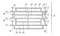
通気部20および排水部30は、具体的には、図3に示すように構成されている。
すなわち、通気部20は、有孔シートパイプ10の一方の端部10aに接続された変換継手50と、この変換継手50に接続された塩化ビニル樹脂製の直管からなる接続管11aと、この接続管11aに接続された分岐継手40と、この分岐継手40に接続された塩化ビニル樹脂製の直管からなる接続管11bと、この接続管11bに接続された可撓性管60と、この可撓性管60に接続された塩化ビニル樹脂製の直管からなる立上がり管14とを具備して構成されている。そして、立上がり管14の末端14aが大気中に突出することで、暗渠パイプ内の通気が保たれるようになっている。立上がり管14の末端14aには、通常、通気孔付キャップ15が嵌められている。
一方、排水部30は、有孔シートパイプ10の一方の端部10bに接続された変換継手50と、この変換継手50に接続された塩化ビニル樹脂製の直管からなる接続管11aと、この接続管11aに接続された分岐継手40と、この分岐継手40に接続された塩化ビニル樹脂製の直管からなる接続管11bと、この接続管11bに接続された可撓性管60と、この可撓性管60に接続された塩化ビニル樹脂製の直管からなる排水管16とを具備して構成されている。そして、排水管16の末端16aが排水溝Dの側面から大気中に突出することで、暗渠パイプ内に集水された余剰水が排水溝Dに排水されるようになっている。排水管16の末端16aには、水閘17が嵌められている。
The
That is, the
On the other hand, the
図4は、この例で使用されている変換継手50を示す図である。
この変換継手50は、塩化ビニル樹脂からなり、有孔シートパイプ10のいずれか一方の端部10a、10bと、これに対向するように配置された接続管11aの一方の端部とが液密に接続される直管状のものであって、いずれも断面円形である雌型の小径接続口50aと雌型の大径接続口50bとが形成されている。小径接続口50aには有孔シートパイプの端部10a、10bが液密に挿入され、大径接続口50bには有孔シートパイプよりも大径の接続管11aの端部が液密に挿入される。小径接続口50aおよび大径接続口50bがいずれも雌型であると、接続部分を縮径することなく接続することができる。また、この例では図示のように、小径接続口50aには、内面取り加工が施され、有孔シートパイプ10の端部10a、10bが挿入されやすいようになっている。
また、この変換継手50を接続する際において、大径接続口50bにおける接続には接着剤が使用され、大径接続口50bと接続管11aの端部とは接合される。一方、小径接続口50aにおける接続には接着剤は使用されず、有孔シートパイプ10の端部10a、10bが単に挿入されるだけであり、敷設時に長さ調整がしやすく、また、敷設後には、気温などの外因による有孔シートパイプ10、接続管11aなどの膨張、収縮を吸収できるようにされている。
FIG. 4 is a view showing the conversion joint 50 used in this example.
The conversion joint 50 is made of a vinyl chloride resin, and one
Moreover, when connecting this
このような変換継手50の製法としては、射出成形法が例示できる。また、塩化ビニル樹脂製の直管を用意し、その一方の端部をオイルバスなどにより加温して軟化させ、ついで、軟化した端部にこの直管よりも大径の金型を挿入後、冷却して、この端部を拡径する方法が例示できる。
このような変換継手50を使用すると、通気部20および排水部30において、有孔シートパイプ10の端部10a、10bと接続管11aの端部とを液密性よく接続することができ、この接続部分における水漏れを防止し、余剰水の排水や暗渠パイプの洗浄を効率的に行うことができる。
An example of a method for producing such a conversion joint 50 is an injection molding method. In addition, a straight pipe made of vinyl chloride resin is prepared, and one end of the pipe is heated and softened with an oil bath or the like, and then a mold having a diameter larger than that of the straight pipe is inserted into the softened end. A method of cooling and expanding the diameter of this end can be exemplified.
When such a conversion joint 50 is used, the
図5は、この例で使用されている分岐継手40を示す図である。
この分岐継手40は、塩化ビニル樹脂製の射出成形体であり、この分岐継手40には、塩化ビニル樹脂製の直管からなる接続管11a、11bがそれぞれ液密に挿入される2つの雌型の接続口40a、40bが互いに対向する位置に形成され、塩化ビニル樹脂製の直管からなる連通管18がそれぞれ液密に挿入される2つの雌型の接続口40c、40dが互いに対向する位置に形成されている。これら4つの接続口40a〜40dは、隣接する接続口同士のなす角度がいずれも90度となるように、すなわち十字に形成されている。また、これら4つの接続口40a〜40dは、いずれも断面円形で同径とされている。各接続口40a〜40dがいずれも雌型であると、接続部分を縮径することなく接続することができる。
また、この例では、各接続口40a〜40dにおける接続には接着剤が使用され、各接続口40a〜40dとそれに挿入された接続管11a、11bおよび連通管18の端部とは接合される。
FIG. 5 is a view showing the branch joint 40 used in this example.
This branch joint 40 is an injection-molded body made of vinyl chloride resin. In this branch joint 40, two female molds into which connecting
In this example, an adhesive is used for connection at each of the
このような分岐継手40を使用すると、通気部20および排水部30において、2本の連通管18と、2本の接続管11a、11bとの合計4本を1つの部材で接続することができ、従来のように2つのT字継手12を連結して使用する必要がなくなる。よって、暗渠パイプの敷設に使用される接続部品数を抑制することができる。また、接続口40a〜40dが十字に形成されているため、図2のように接続管11a、11bおよび連通管18を直角に連結して、図1のような暗渠パイプを構成することができる。
When such a branch joint 40 is used, a total of four of the two
図6は、この例で使用されている可撓性管60を示す図である。
この可撓性管60は、曲折自在な可撓性管本体61と、その両端に接着剤63により接合された塩化ビニル樹脂製の直管状の継手62とからなるものである。ここで使用されている各継手62には、可撓性管本体61が液密に挿入される雌型の大径接続口62aと、これよりも小さな径からなる雌型の小径接続口62bとがそれぞれ形成されている。
この可撓性管60は、通気部20においては、一方の継手62の小径接続口62bには立上がり管14が液密に挿入され、可撓性管本体61が適度な角度で上方に曲げられることで、立上がり管14の末端14aが大気中に突出するようにされている。他方の継手62の小径接続口62bには、接続管11bが液密に挿入される。
一方、排水部30においては、一方の継手62の小径接続口62bには排水管16が液密に接続され、可撓性管本体61が適度な角度で下方に曲げられることで、排水管16の末端16aが排水溝Dの側面から大気中に突出するようにされている。他方の継手62の小径接続口62bには、接続管11bが液密に挿入される。
小径接続口62bおよび大径接続口62aがいずれも雌型であると、接続部分を縮径することなく接続することができる。
また、この例では、小径接続口62bにおける接続にも接着剤が使用され、小径接続口62bとそれに挿入された接続管11b、立上がり管14、排水管16の各端部とは接合される。
可撓性管本体61としては、塩化ビニル樹脂などの樹脂からなるコルゲート管や、ダクト管、ゴム管などが挙げられ、可撓性を備えたものであればよい。
FIG. 6 is a diagram showing a
The
In the
On the other hand, in the
When both the small-
Further, in this example, an adhesive is also used for connection at the small
Examples of the flexible tube
このような可撓性管60を使用すると、通気部20および排水部30において、可撓性管本体61と、接続管11b、立ち上がり管14、排水管16とをそれぞれ液密性よく接続することができ、この接続部分における水漏れを防止し、余剰水の排水や暗渠パイプの洗浄を効率的に行うことができる。
なお、この例では、直管状の継手62を使用しているが、必要に応じて、大径接続口62aと小径接続口62bとのなす角度が180度以外である曲管状の継手を用いてもよい。
また、可撓性管は、可撓性管本体61の一方の端部のみに、継手62が接合されたものであってもよい。その場合、この継手62の小径接続口62bには接続管11bが接続される。可撓性管本体61において、継手62が接合されていない側の端部は、通気部20においては、そのまま土壌Sから大気中に突出させ、排水部30においては、排水溝Dの側面から大気中に突出させればよい。そのようにすると、通水部20では立上がり管14を使用する必要がなくなり、排水部30では排水管16を使用する必要がなくなるため、暗渠パイプの敷設に使用される接続部品数を抑制することができる。
When such a
In this example, a straight tubular joint 62 is used, but if necessary, a curved tubular joint whose angle between the large
Further, the flexible tube may be one in which the joint 62 is joined to only one end of the flexible tube
S 土壌
10、10’有孔シートパイプ
40 分岐継手
40a〜40d 接続口
50 変換継手
50a 小径接続口
50b 大径接続口
60 可撓性管
61 可撓性管本体
62 継手
Claims (5)
有孔シートパイプが液密に挿入される雌型の小径接続口と、前記有孔シートパイプよりも大径の樹脂製の直管が液密に挿入される雌型の大径接続口とが形成されたことを特徴とする変換継手。 A conversion joint used for a culvert pipe that drains surplus water in soil,
A female-type small-diameter connection port into which the perforated sheet pipe is inserted in a liquid-tight manner and a female-type large-diameter connection port into which a straight resin pipe having a larger diameter than the perforated sheet pipe is inserted in a liquid-tight manner. A conversion joint characterized by being formed.
樹脂製の直管が液密に挿入される雌型の接続口が4つ形成され、かつ、これらの接続口が十字に形成されたことを特徴とする分岐継手。 A branch joint used for a culvert pipe that drains surplus water in the soil,
A branch joint characterized in that four female connection ports into which a resin straight pipe is inserted in a liquid-tight manner are formed, and these connection ports are formed in a cross shape.
可撓性管本体と、該可撓性管本体の少なくとも一端に接合され、該可撓性管本体と樹脂製の直管とを液密に接続する継手とを備えていることを特徴とする可撓性管。 A flexible pipe used for a culvert pipe that drains excess water in the soil,
A flexible tube main body and a joint that is joined to at least one end of the flexible tube main body and that fluid-tightly connects the flexible tube main body and a resin straight pipe are provided. Flexible tube.
有孔シートがパイプ状に成形された有孔シートパイプと、
複数の樹脂製の直管と、
前記有孔シートパイプが液密に挿入される雌型の小径接続口と、前記有孔シートパイプよりも大径の樹脂製の直管が液密に挿入される雌型の大径接続口とが形成された変換継手と、
樹脂製の直管が液密に挿入される雌型の接続口が4つ形成され、かつ、これらの接続口が十字に形成された分岐継手と、
可撓性管本体と、該可撓性管本体の少なくとも一端に接合され、該可撓性管本体と樹脂製の直管とを液密に接続する継手とを備えた可撓性管、を具備して構成されたことを特徴とする暗渠パイプ。 A culvert pipe that drains excess water in the soil,
A perforated sheet pipe in which a perforated sheet is formed into a pipe shape;
A plurality of resin straight pipes;
A female-type small-diameter connection port into which the perforated sheet pipe is inserted in a liquid-tight manner, and a female-type large-diameter connection port into which a resin straight pipe having a larger diameter than the perforated sheet pipe is inserted in a liquid-tight manner A conversion joint formed with
A branch joint in which four female connection ports into which resin straight pipes are inserted in a liquid-tight manner are formed, and these connection ports are formed in a cross shape;
A flexible tube comprising: a flexible tube main body; and a joint that is bonded to at least one end of the flexible tube main body and fluidly connects the flexible tube main body and a resin straight pipe. A culvert pipe characterized by comprising.
Priority Applications (1)
| Application Number | Priority Date | Filing Date | Title |
|---|---|---|---|
| JP2009096069A JP2010249155A (en) | 2009-04-10 | 2009-04-10 | Conversion joint for culvert pipe, branch joint, flexible pipe, and culvert pipe using branch joint and flexible pipe |
Applications Claiming Priority (1)
| Application Number | Priority Date | Filing Date | Title |
|---|---|---|---|
| JP2009096069A JP2010249155A (en) | 2009-04-10 | 2009-04-10 | Conversion joint for culvert pipe, branch joint, flexible pipe, and culvert pipe using branch joint and flexible pipe |
Publications (1)
| Publication Number | Publication Date |
|---|---|
| JP2010249155A true JP2010249155A (en) | 2010-11-04 |
Family
ID=43311723
Family Applications (1)
| Application Number | Title | Priority Date | Filing Date |
|---|---|---|---|
| JP2009096069A Pending JP2010249155A (en) | 2009-04-10 | 2009-04-10 | Conversion joint for culvert pipe, branch joint, flexible pipe, and culvert pipe using branch joint and flexible pipe |
Country Status (1)
| Country | Link |
|---|---|
| JP (1) | JP2010249155A (en) |
Citations (7)
| Publication number | Priority date | Publication date | Assignee | Title |
|---|---|---|---|---|
| JPS5845732U (en) * | 1981-09-18 | 1983-03-28 | 西村産業株式会社 | Underdrain drain pipe made from recycled waste plastic |
| JPS5961332U (en) * | 1982-10-08 | 1984-04-21 | 大日本プラスチツクス株式会社 | Underdrain drainage pipe fittings |
| JP3042092U (en) * | 1997-04-02 | 1997-10-07 | 正明 宮嶋 | Underdrain drainage valve |
| JP3100872U (en) * | 2003-10-06 | 2004-05-27 | 株式会社パディ研究所 | Pipe fittings |
| JP2006241855A (en) * | 2005-03-03 | 2006-09-14 | Jitetsuku:Kk | Drainage culvert formation device |
| JP2007502352A (en) * | 2003-08-13 | 2007-02-08 | ダウ グローバル テクノロジーズ インコーポレイティド | Piping system and piping joining method to apparatus, fixture, device, structure and instrument |
| JP2008025760A (en) * | 2006-07-24 | 2008-02-07 | Kanaflex Corporation | Pipe joint structure |
-
2009
- 2009-04-10 JP JP2009096069A patent/JP2010249155A/en active Pending
Patent Citations (7)
| Publication number | Priority date | Publication date | Assignee | Title |
|---|---|---|---|---|
| JPS5845732U (en) * | 1981-09-18 | 1983-03-28 | 西村産業株式会社 | Underdrain drain pipe made from recycled waste plastic |
| JPS5961332U (en) * | 1982-10-08 | 1984-04-21 | 大日本プラスチツクス株式会社 | Underdrain drainage pipe fittings |
| JP3042092U (en) * | 1997-04-02 | 1997-10-07 | 正明 宮嶋 | Underdrain drainage valve |
| JP2007502352A (en) * | 2003-08-13 | 2007-02-08 | ダウ グローバル テクノロジーズ インコーポレイティド | Piping system and piping joining method to apparatus, fixture, device, structure and instrument |
| JP3100872U (en) * | 2003-10-06 | 2004-05-27 | 株式会社パディ研究所 | Pipe fittings |
| JP2006241855A (en) * | 2005-03-03 | 2006-09-14 | Jitetsuku:Kk | Drainage culvert formation device |
| JP2008025760A (en) * | 2006-07-24 | 2008-02-07 | Kanaflex Corporation | Pipe joint structure |
Similar Documents
| Publication | Publication Date | Title |
|---|---|---|
| CN103290893B (en) | Double-hole drainage pipe | |
| JP2010249155A (en) | Conversion joint for culvert pipe, branch joint, flexible pipe, and culvert pipe using branch joint and flexible pipe | |
| CN207812420U (en) | One kind being used for agricultural irrigation Seeper discharge device | |
| CN214994354U (en) | Water collection device convenient to overhaul | |
| JP4390565B2 (en) | Drainage adapter and drainage structure | |
| CN207714650U (en) | A kind of integrated skirting | |
| CN205314185U (en) | Double cannula formula toilet bowl drainage device | |
| KR20110093498A (en) | Drainpipe having v-shape inner structure | |
| CN206708608U (en) | A kind of apron socket joint throttle type winding reinforcing pipe | |
| JP2008025128A (en) | Riser pipe | |
| JP2007308961A (en) | Horizontal piping joint and drain pipeline structure using it | |
| CN205171650U (en) | Heavy pond of pre -buried formula floor floor drain | |
| CN204986065U (en) | Detachable sewer pipe | |
| KR101521419B1 (en) | The variable drainpipe of drain and connecting method of the drainpipe | |
| CN204840662U (en) | Flowing back connects | |
| JP2023078021A (en) | Piping structure and pipe joint | |
| CN201803033U (en) | Auto sunroof water drain pipe connecting structure | |
| CN216108882U (en) | Bathroom facing brick dry and hard mortar anchor coat drainage device | |
| JP6222932B2 (en) | Branch pipe, drainage pipe structure including the branch pipe, and branch pipe connection method | |
| JP6564321B2 (en) | Drainage pipe structure and joint used in the drainage pipe structure | |
| JP2010077696A (en) | Repair drain made of soft thermoplastic resin, molding method of repair drain made of soft thermoplastic resin, and repair drain structure | |
| JP5327689B2 (en) | unit bus | |
| KR20000002077A (en) | Mold for connecting drain tube and connecting method thereof | |
| CN207277451U (en) | A kind of Homofloor drainage system | |
| JP2006214204A (en) | Siphon drainage system |
Legal Events
| Date | Code | Title | Description |
|---|---|---|---|
| A621 | Written request for application examination |
Free format text: JAPANESE INTERMEDIATE CODE: A621 Effective date: 20110907 |
|
| A131 | Notification of reasons for refusal |
Free format text: JAPANESE INTERMEDIATE CODE: A131 Effective date: 20130226 |
|
| A521 | Written amendment |
Free format text: JAPANESE INTERMEDIATE CODE: A523 Effective date: 20130426 |
|
| A02 | Decision of refusal |
Free format text: JAPANESE INTERMEDIATE CODE: A02 Effective date: 20130903 |