JP2010242761A - Reduction device for gas pressure applied to piston ring package of reciprocating engine - Google Patents
Reduction device for gas pressure applied to piston ring package of reciprocating engine Download PDFInfo
- Publication number
- JP2010242761A JP2010242761A JP2010086626A JP2010086626A JP2010242761A JP 2010242761 A JP2010242761 A JP 2010242761A JP 2010086626 A JP2010086626 A JP 2010086626A JP 2010086626 A JP2010086626 A JP 2010086626A JP 2010242761 A JP2010242761 A JP 2010242761A
- Authority
- JP
- Japan
- Prior art keywords
- piston
- piston head
- ring
- reduction device
- scraping
- Prior art date
- Legal status (The legal status is an assumption and is not a legal conclusion. Google has not performed a legal analysis and makes no representation as to the accuracy of the status listed.)
- Pending
Links
- 230000009467 reduction Effects 0.000 title claims abstract description 35
- 238000002485 combustion reaction Methods 0.000 claims abstract description 60
- 238000007790 scraping Methods 0.000 claims abstract description 55
- 230000008021 deposition Effects 0.000 claims description 4
- 238000005498 polishing Methods 0.000 abstract description 31
- 238000005299 abrasion Methods 0.000 abstract 1
- 239000007789 gas Substances 0.000 description 20
- 230000000694 effects Effects 0.000 description 11
- 238000007789 sealing Methods 0.000 description 11
- 230000008901 benefit Effects 0.000 description 5
- 238000010586 diagram Methods 0.000 description 5
- 230000002000 scavenging effect Effects 0.000 description 5
- 238000012423 maintenance Methods 0.000 description 4
- 230000009471 action Effects 0.000 description 3
- 239000000446 fuel Substances 0.000 description 3
- 239000000567 combustion gas Substances 0.000 description 2
- 230000006835 compression Effects 0.000 description 2
- 238000007906 compression Methods 0.000 description 2
- 239000000295 fuel oil Substances 0.000 description 2
- 239000000314 lubricant Substances 0.000 description 2
- 239000010687 lubricating oil Substances 0.000 description 2
- 238000005461 lubrication Methods 0.000 description 2
- 239000002245 particle Substances 0.000 description 2
- 230000008439 repair process Effects 0.000 description 2
- 240000001973 Ficus microcarpa Species 0.000 description 1
- 230000003466 anti-cipated effect Effects 0.000 description 1
- 230000008859 change Effects 0.000 description 1
- 230000001010 compromised effect Effects 0.000 description 1
- 239000000470 constituent Substances 0.000 description 1
- 230000001419 dependent effect Effects 0.000 description 1
- 238000009826 distribution Methods 0.000 description 1
- 238000010438 heat treatment Methods 0.000 description 1
- 230000006872 improvement Effects 0.000 description 1
- 239000007788 liquid Substances 0.000 description 1
- 239000000203 mixture Substances 0.000 description 1
- 239000003921 oil Substances 0.000 description 1
- 239000007787 solid Substances 0.000 description 1
- 239000004071 soot Substances 0.000 description 1
- 239000000126 substance Substances 0.000 description 1
- 238000013334 tissue model Methods 0.000 description 1
- 238000009827 uniform distribution Methods 0.000 description 1
- 239000008207 working material Substances 0.000 description 1
Images


Classifications
-
- F—MECHANICAL ENGINEERING; LIGHTING; HEATING; WEAPONS; BLASTING
- F02—COMBUSTION ENGINES; HOT-GAS OR COMBUSTION-PRODUCT ENGINE PLANTS
- F02F—CYLINDERS, PISTONS OR CASINGS, FOR COMBUSTION ENGINES; ARRANGEMENTS OF SEALINGS IN COMBUSTION ENGINES
- F02F1/00—Cylinders; Cylinder heads
- F02F1/18—Other cylinders
-
- F—MECHANICAL ENGINEERING; LIGHTING; HEATING; WEAPONS; BLASTING
- F02—COMBUSTION ENGINES; HOT-GAS OR COMBUSTION-PRODUCT ENGINE PLANTS
- F02F—CYLINDERS, PISTONS OR CASINGS, FOR COMBUSTION ENGINES; ARRANGEMENTS OF SEALINGS IN COMBUSTION ENGINES
- F02F1/00—Cylinders; Cylinder heads
- F02F2001/006—Cylinders; Cylinder heads having a ring at the inside of a liner or cylinder for preventing the deposit of carbon oil particles, e.g. oil scrapers
Landscapes
- Engineering & Computer Science (AREA)
- Chemical & Material Sciences (AREA)
- Combustion & Propulsion (AREA)
- Mechanical Engineering (AREA)
- General Engineering & Computer Science (AREA)
- Pistons, Piston Rings, And Cylinders (AREA)
- Cylinder Crankcases Of Internal Combustion Engines (AREA)
Abstract
Description
本発明は、往復動機関のピストンリング・パッケージと、ピストンと、取り外し可能な掻き落としリングと、シリンダとに加わるガス圧の低減装置、並びに独立請求項の上位概念部分に記載の往復動機関、特に2サイクル大型ディーゼル機関に関するものである。 The present invention provides a piston ring package of a reciprocating engine, a piston, a removable scraping ring, a device for reducing gas pressure applied to a cylinder, and a reciprocating engine according to the upper conceptual part of the independent claim, In particular, it relates to a two-cycle large diesel engine.
往復動機関用、例えば2サイクル大型ディーゼル機関用、特にユニフロー掃気式2サイクル大型ディーゼル機関用の、従来技術により公知のピストンは、通例、各ピストンリング溝内に上下に配置された複数ピストンリングから成るパッケージを備えている。通常、公知のピストンリング・パッケージは、少なくとも2個のピストンリングから成るが、大抵は、往復動機関の出力の大きさ又は構造に応じて、又は機関の作動に対する要求及び特殊な作動条件に応じて、3個、4個、更には5個から成っている。複数のピストンリングは、その場合、全く異なる機能を有している。例えば、シリンダ滑り面での潤滑油の分配及び/又は掻き落とし、クランクケースに対する燃焼室のシール、ユニフロー掃気式2サイクル大型ディーゼル機関の場合には、受容室に対するシール等である。 Pistons known from the prior art for reciprocating engines, for example for two-cycle large diesel engines, in particular for uniflow scavenging two-cycle large diesel engines, typically consist of a plurality of piston rings arranged vertically in each piston ring groove. It has a package consisting of Known piston ring packages usually consist of at least two piston rings, but mostly depend on the magnitude or structure of the output of the reciprocating engine or on the requirements and special operating conditions of the engine operation. It consists of three, four, and even five. In this case, the plurality of piston rings have completely different functions. For example, distribution and / or scraping of lubricant oil on the cylinder sliding surface, sealing of the combustion chamber to the crankcase, sealing to the receiving chamber in the case of a uniflow scavenging two-cycle large diesel engine.
通常、ユニフロー掃気式2サイクル大型ディーゼル機関の場合、受容室に向いたピストン下側に対し燃焼室をシールするための4個又は5個から成るピストンリング・パッケージが使用される。受容室からは、掃気段階の始めに掃気口を通って新気がシリンダ燃焼室内へ流入する。リング・ジョイントに応じて、下側の複数ピストンリングには、多少の差はあれ著しい負荷がかかる。その場合、下側ピストンリング間には、往々にして異なる不安定状態が生じ、それらの不安定状態が、例えば圧力変動を生じさせ、この圧力変動が、またピストンの不安定な動作を引き起こす。これは、類似の又は等しい機能を有するピストンリングが多過ぎるからである。 Typically, in the case of a uniflow scavenging two-cycle large diesel engine, four or five piston ring packages are used to seal the combustion chamber against the underside of the piston facing the receiving chamber. From the receiving chamber, fresh air flows into the cylinder combustion chamber through the scavenging port at the beginning of the scavenging stage. Depending on the ring joint, the lower multi-piston ring is subject to significant loads, with some differences. In that case, different unstable states often occur between the lower piston rings, and these unstable states cause, for example, pressure fluctuations, which in turn cause unstable movements of the piston. This is because there are too many piston rings with similar or equal functions.
大型ディーゼル機関は、しばしば、船舶の駆動装置として、又は定置の駆動装置、例えば電気エネルギーを発生させるための大型発電機の駆動装置として使用される。その場合、機関は、かなり長時間にわたって連続稼働をするため、作動の安全性および有効性に対して高い要求が課せられている。したがって、操業者にとっては、保守間隔が長いこと、摩耗が小さいこと、燃料及び作動物質に関して経済的であることが、機関の稼働の中心的基準となる。とりわけ、シリンダ穴が大きい緩速ディーゼル機関のピストンの動作は、保守間隔の長さや有効性に、また潤滑油消費の点で直接に稼働費用に、ひいては経済性に係わる決定的な要因である。このため、機関のシリンダ潤滑の複合的問題が、次第に重要な意味を持つようになっている。そのさい、特に大型ディーゼル機関の場合、シリンダの潤滑は、往復動するピストン内の潤滑装置により行われるか、又はシリンダ壁内に設けられた潤滑油ノズルによって行われる。 Large diesel engines are often used as ship drives or as stationary drives, for example large generator drives for generating electrical energy. In that case, since the engine operates continuously for a considerably long time, high demands are imposed on the safety and effectiveness of operation. Thus, for operators, long maintenance intervals, low wear, and economics with respect to fuel and working materials are the central criteria for engine operation. In particular, the operation of the piston of a slow diesel engine having a large cylinder hole is a decisive factor relating to the length and effectiveness of the maintenance interval and directly in terms of operating costs and in terms of economy, in terms of lubricating oil consumption. For this reason, the complex problem of engine cylinder lubrication is becoming increasingly important. In particular, in the case of a large diesel engine, the cylinder is lubricated by a lubrication device in a reciprocating piston or by a lubricating oil nozzle provided in the cylinder wall.
内燃機関の作動時に再三問題になる点は、エンジン内の異なる箇所に付着する燃焼残渣である。とりわけ、重油で運転されることが多い2サイクル大型ディーゼル機関の場合には、燃焼残渣が大きな問題となる。なぜなら、使用燃料、つまり重油は、固体、液体、気体、あらゆる種類の燃焼残渣を発生させる多くの物質を含有し、それらの残渣が、特にピストン、ピストンリング溝に付着し、とりわけピストンヘッド又はシリンダにも、特に上死点の近くで付着するからである。 The problem that occurs repeatedly during the operation of the internal combustion engine is combustion residue adhering to different locations in the engine. In particular, in the case of a two-cycle large diesel engine that is often operated with heavy oil, combustion residue is a major problem. This is because the fuel used, that is, heavy oil, contains many substances that generate solids, liquids, gases, and all kinds of combustion residues, and these residues adhere to pistons, piston ring grooves, in particular piston heads or cylinders. In particular, it adheres near the top dead center.
特にピストンヘッドの燃焼残渣を掻き落とすために、例えばバルチラ(Waertsilae)社の2サイクル機関の場合、シリンダライナーの上部にいわゆるアンチポリッシング・リングを備えることが知られている、このリングは、例えば長方形断面を有する薄壁スリーブとして構成され、通常、シリンダ自体の内径より小さい内径を有している。この縮径によって、ピストンヘッドのところで掻き落とし効果が発生する。アンチポリッシング・リングの内径は、その場合、ピストンヘッドの直径、しかもエンジン作動時のピストンヘッドの最大直径によって決められる。したがって、公知のアンチポリッシング・リングの場合、その内径を、ピストンヘッドとリングとの間隙ができるだけ小さくなるように、しかもピストンヘッドがリングと機械的に直接接触しないように設計することが求められる。 In order to scrape off the combustion residues of the piston head in particular, it is known, for example in the case of a two-stroke engine from the company Waertsilae, to have a so-called anti-polishing ring on the top of the cylinder liner. It is configured as a thin-walled sleeve having a cross section and usually has an inner diameter that is smaller than the inner diameter of the cylinder itself. This diameter reduction creates a scraping effect at the piston head. The inner diameter of the anti-polishing ring is then determined by the diameter of the piston head and the maximum diameter of the piston head during engine operation. Therefore, in the case of known anti-polishing rings, it is required that the inner diameter be designed so that the gap between the piston head and the ring is as small as possible and that the piston head is not in direct mechanical contact with the ring.
アンチポリッシング・リングの構成のさいには、極めて多くの点で妥協せざるを得ないことは明らかである。負荷が低く、ピストンヘッドが冷えている場合には、熱膨張効果が低いため、それだけで遊び、つまりピストンヘッド/リング間隔が、高負荷の場合より大となる。その場合、付加的に考えねばならないのは、一般に、シリンダ内の種々の構成要素、例えばシリンダ滑り面、ピストン、特にピストンリング、ピストンリング溝が、ピストンヘッドも含めて、周方向にも縦方向にも作動時間数に応じて様々に摩耗し、このため一定不変の直径を有さない点である。
したがって、従来技術による公知機関の場合、アンチポリッシング・リングとピストンヘッドとが、あらゆる作動条件下で、また関与する構成要素の全有効寿命にわたって、最適に協働するわけではないことが明らかである。
Obviously, the configuration of the anti-polishing ring must be compromised in numerous ways. When the load is low and the piston head is cold, the thermal expansion effect is low, so that play alone, that is, the piston head / ring interval is larger than that under high load. In that case, the additional consideration is generally that the various components in the cylinder, for example the cylinder sliding surface, the piston, in particular the piston ring, the piston ring groove, both in the circumferential direction and in the longitudinal direction, including the piston head, However, it wears variously depending on the number of operating hours, and therefore does not have a constant diameter.
Thus, in the case of prior art known engines, it is clear that the anti-polishing ring and the piston head do not cooperate optimally under all operating conditions and over the entire useful life of the components involved. .
とりわけ、アンチポリッシング・リングとピストンヘッド双方を上死点近くで協働させて実際にシールしようとする場合、どのような場合でも、双方の間に最適シール効果が保証されるとは限らない。燃焼残渣の掻き落としのほかに、アンチポリッシング・リング/ピストンヘッド対の重要な役割は、圧縮行程時、つまりは燃料点火時にピストン上死点近くでシリンダ燃焼室内に発生する極めて高いガス圧をピストンの下側に対し、ひいては特にピストンヘッド下方のピストンリング・パッケージに対してシールすることである。 In particular, when the anti-polishing ring and the piston head are both close to top dead center and are actually sealed, the optimum sealing effect is not always guaranteed between them. In addition to scraping off combustion residues, the important role of the anti-polishing ring / piston head pair is to generate a very high gas pressure generated in the cylinder combustion chamber near the top dead center of the piston during the compression stroke, that is, during fuel ignition. Sealing against the underside, and in particular against the piston ring package below the piston head.
したがって、特に保証されねばならないのは、燃焼室内に上死点近くで発生する圧力エネルギーを出来るだけ完全に利用可能にし、利用されないままガス流形態でピストンを擦り抜けてシリンダの下部へ、かつまた受容室内へ流入する部分がないようにすることである。加えて、アンチポリッシング・リング/ピストンヘッド間のシールが不十分な場合には、ピストンを擦り抜けて下方へ流れるガス流によって、燃焼残渣の付着物から個々の粒子が制御不能に剥奪されて、例えばシリンダ下部のシリンダ滑り面に往々にして付着し、それによって、もとよりシリンダ潤滑油が汚染され、最悪の場合には、掻き疵等の損傷を生じる危険が常に存在する。 Therefore, it must be particularly ensured that the pressure energy generated near top dead center in the combustion chamber is made available as completely as possible, and is squeezed through the piston in the form of a gas flow to the lower part of the cylinder. It is to make sure that no part flows into the receiving chamber. In addition, if the seal between the anti-polishing ring / piston head is inadequate, the gas flow that rubs down the piston and flows downward will cause individual particles to be uncontrollably stripped from the deposits of combustion residues, For example, it often adheres to the cylinder sliding surface at the bottom of the cylinder, thereby naturally contaminating the cylinder lubricant, and in the worst case there is always a risk of causing damage such as scraping.
本発明の課題は、したがって、特にピストン上死点近くで燃焼室/ピストン下側間のシールの改善を補助する装置を提供することである。特に、本発明の課題は、作動時にピストンリング・パッケージに作用するガス圧を低減し、しかも、作動状態又は関与する構成要素の摩耗状態とは無関係に、ピストン上死点近くでピストンヘッド/アンチポリッシング・リング間の最適シールが常に自動的に達成されるようにすることである。 The object of the present invention is therefore to provide a device which helps to improve the seal between the combustion chamber / bottom piston, especially near the top dead center of the piston. In particular, it is an object of the present invention to reduce the gas pressure acting on the piston ring package during operation, and the piston head / anti-near piston near top dead center, regardless of the operating state or the wear state of the components involved. It is to ensure that the optimum seal between the polishing rings is always achieved automatically.
この課題を解決する本発明の主題は、独立請求項に記載の特徴を有している。
従属請求項は、本発明の特に好ましい実施例に関係するものである。
The subject matter of the present invention which solves this problem has the features described in the independent claims.
The dependent claims relate to particularly preferred embodiments of the invention.
本発明は、したがって、往復動機関の作動時に、ピストンリング区域に配置されたピストンリング・パッケージに作用するガス圧の低減装置に関するものである。ピストンは、その場合、ピストンリング区域に隣接するピストンヘッドが含まれ、ピストンヘッドは、組み付け状態では往復動機関の燃焼室側に位置している。ピストンは、作動時、シリンダ長手軸線に沿って往復動するように配置されており、それにより、ピストンのピストンヘッドは、シリンダ内での運動の上死点近くで、シリンダ壁に設けた掻き落とし装置と協働して燃焼残渣の掻き落としを制御する。この場合、ガス圧低減装置は切り欠き形式に構成されており、低減装置への燃焼残渣の付着を制御可能である。本発明による掻き落とし装置とピストンヘッドとは、少なくとも停止温度時に、予め設定可能の角度で少なくとも部分的に互いに傾斜するように構成かつ相互配置され、それにより上死点近くでピストンヘッドが掻き落とし装置と協働するさい、ピストンリング・パッケージに作用するガス圧が自動的に調節可能に低減される。 The invention therefore relates to a device for reducing the gas pressure acting on a piston ring package arranged in a piston ring section during operation of a reciprocating engine. The piston then includes a piston head adjacent to the piston ring section, which is located on the combustion chamber side of the reciprocating engine in the assembled state. The piston is arranged to reciprocate along the longitudinal axis of the cylinder in operation, so that the piston head of the piston is scraped off on the cylinder wall near the top dead center of movement in the cylinder. Control scraping of combustion residue in cooperation with the device. In this case, the gas pressure reducing device is configured in a notch form, and adhesion of combustion residues to the reducing device can be controlled. The scraping device and the piston head according to the present invention are constructed and interleaved so that they are at least partially inclined with respect to each other at a pre-settable angle at least at a stop temperature, whereby the piston head is scraped off near top dead center In cooperation with the device, the gas pressure acting on the piston ring package is automatically adjustable and reduced.
「停止温度」の概念は、この場合、非作動状態で十分に長い間待機した後にエンジンが示す温度という意味である。したがって、停止温度とは、エンジンが十分に長時間停止して、事実上周囲温度と等しい場合には、事実上周囲温度と理解してよい。周囲温度と区別するには、エンジン又はエンジンの種々の部分の作動温度を知らねばならない。当業者には周知のように、作動温度とは、エンジン又はエンジンの個々の部分が作動状態で示す温度である。
本発明にとって重要な利点は、シリンダ、つまり掻き落とし装置又はガス圧低減装置とピストンヘッドとの間の断面(間隔)が変化する点である。
The concept of “stop temperature” in this case means the temperature that the engine exhibits after waiting for a sufficiently long time in a non-operating state. Thus, the stop temperature may be understood as effectively the ambient temperature if the engine has been stopped for a sufficiently long time and is substantially equal to the ambient temperature. To distinguish from ambient temperature, the operating temperature of the engine or various parts of the engine must be known. As is well known to those skilled in the art, the operating temperature is the temperature that the engine or individual parts of the engine exhibit in operation.
An important advantage for the present invention is that the cross section (interval) between the cylinder, i.e. the scraping device or gas pressure reducing device, and the piston head changes.
構成部材、すなわち掻き落とし装置、つまり低減装置とピストンヘッドとは、常温状態では、つまり停止温度時には、互いに平行にならないように構成するのが好ましい。その場合、掻き取り装置、つまり低減装置とピストンヘッドとの対向面は、例えば球形、波形、段階形式のいずれかに構成できる。
ピストンヘッドは、好ましくは、燃焼室方向に向かって先細の円錐形状を有し、掻き落としリングは、変形度に応じて、燃焼室に向かって閉じるか、又はその逆の形状を有している。別の実施例では、言うまでもなく、双方の対向面のうちの一方のみが、好ましくはピストンヘッドが変化する断面を有することができる。
It is preferable that the constituent members, that is, the scraping device, that is, the reduction device and the piston head are configured not to be parallel to each other in the normal temperature state, that is, at the stop temperature. In that case, the scraping device, that is, the opposing surface of the reduction device and the piston head can be configured in any one of a spherical shape, a corrugated shape, and a stepped shape, for example.
The piston head preferably has a tapered conical shape towards the combustion chamber, and the scraping ring closes towards the combustion chamber or vice versa depending on the degree of deformation. . In another embodiment, it goes without saying that only one of the two opposing surfaces can preferably have a cross section in which the piston head varies.
その場合、本発明の特別な利点は、構成要素が作動時に加熱される結果、切り欠き形式、例えば溝形式に付形された面又は付形されていない面が最適形式で対向し、それにより所望のシールが、例えば残渣の付着した切り欠き又は付着していない切り欠きのラビリンスにより実現する点である。
そのさい、燃焼室に向かって閉じる断面、特に縮小する断面により、残渣の付着の無い、より良好なシールが生じる。これは最小断面が燃焼室に最も近くに位置するからである。
燃焼室に向かって開いている断面、特に拡大する断面は、これに対し、煤粒子のより急速な付着を生じさせるが、これは、予想される温度上昇と断面の増大のためである。
In that case, a particular advantage of the present invention is that the components are heated in operation, so that the notched form, e.g. the surface shaped in the groove form or the non-shaped face, is opposed in an optimal manner, thereby The desired seal is achieved, for example, by a labyrinth of a notch with or without a residue attached.
In the meantime, the cross-section closing towards the combustion chamber, in particular the shrinking cross-section, results in a better seal without residue deposits. This is because the smallest cross section is located closest to the combustion chamber.
The cross section that is open towards the combustion chamber, in particular the enlarged cross section, on the other hand, results in a more rapid deposition of soot particles, due to the anticipated temperature rise and cross section increase.
縮小する又は拡大する断面は、好ましくは、通常、垂線に対し、またシリンダ長手軸線に対し、約0.238°〜0.7°の角度を有している。
特に、本発明により、アンチポリッシング・リングの内径は、複数の周方向溝、又は多少の差はあれ細かいネジ山を備えている。この種の切り欠き又は別の幾何形状に構成された切り欠きの機能は、とりわけ、ラビリンス効果を生じさせ得る点にある。ラビリンス効果は、自体公知のシール効果を有し、したがって、ピストンヘッドに沿ってピストンリング・パッケージへ向かって流れ、更にピストン下の区域へ流れる燃焼ガスの体積流量を少なくとも著しく低減させる。これによって、またピストンリング・パッケージに作用する最大ガス圧が低減される。
The reduced or enlarged cross section preferably has an angle of about 0.238 ° to 0.7 °, usually with respect to the normal and to the cylinder longitudinal axis.
In particular, according to the present invention, the inner diameter of the anti-polishing ring is provided with a plurality of circumferential grooves or more or less fine threads. The function of a notch of this kind or of another geometry is, among other things, that it can produce a labyrinth effect. The labyrinth effect has a sealing effect known per se and thus at least significantly reduces the volumetric flow rate of the combustion gas flowing along the piston head towards the piston ring package and further into the area under the piston. This also reduces the maximum gas pressure acting on the piston ring package.
加えて、切り欠きにより溝を付けた表面は、アンチポリッシング・リング又はピストンヘッドの区域のいずれかに、又は双方に設けることができ、燃焼残渣の付着を加速できる。燃焼残渣に覆われたピストンヘッド及び/又はアンチポリッシング・リングの表面により、リング内径、つまりはピストンリング外径が縮径され、アンチポリッシング・リングとピストンリングとの間隔、つまり間隙が縮小する。アンチポリッシング・リングとピストンヘッドとの間隔は、したがって、本発明により作動状態では自動的に最適値に調整される。 In addition, notched grooves can be provided in either the anti-polishing ring or the piston head area, or both, to accelerate the deposition of combustion residues. The inner surface of the ring, that is, the outer diameter of the piston ring is reduced by the surface of the piston head and / or the anti-polishing ring covered with the combustion residue, and the distance between the anti-polishing ring and the piston ring, that is, the gap is reduced. The distance between the anti-polishing ring and the piston head is therefore automatically adjusted to an optimum value in the operating state according to the invention.
例えば、出力を高めて、その結果、ピストンヘッド外径が拡径し、つまりはアンチポリッシング・リング内径が縮径する場合、アンチポリッシング・リング及び/又はピストンリングのところの燃焼残渣の比較的軟質の堆積が、双方の相対運動によって掻き落とされ、それにより、アンチポリッシング・リング/ピストンヘッド間の、つまりこれら構成要素の一方又は双方の残渣堆積表面間の最適間隔が自動的に調整される。これによって、往復動機関の作動状態とは無関係に、かつまた関連エンジン構成要素の摩耗状態とは無関係に、アンチポリッシング・リング/ピストンヘッド間の最適間隔が自動的に常に維持され、その結果、また常に最適シール作用も調整され、したがって、ピストンリング・パッケージに対するガス圧の最大可能な低減が調整される。 For example, if the output is increased so that the outer diameter of the piston head is increased, i.e. the inner diameter of the anti-polishing ring is reduced, the combustion residue at the anti-polishing ring and / or the piston ring is relatively soft. Is scraped off by the relative movement of both, thereby automatically adjusting the optimum spacing between the anti-polishing ring / piston head, ie between the residue deposition surfaces of one or both of these components. This ensures that the optimum spacing between the anti-polishing ring / piston head is always automatically maintained independently of the operating conditions of the reciprocating engine and also regardless of the wear conditions of the relevant engine components, The optimum sealing action is also always adjusted, so that the maximum possible reduction in gas pressure on the piston ring package is adjusted.
加えて、アンチポリッシング・リング/ピストンヘッドの間隔が、そのように減少することによって、燃焼室からピストンリング・パッケージを経てピストンを擦り抜ける燃焼ガスの体積流量が著しく低減される。
既述のように、特に好適な実施例では、好ましくはアンチポリッシング・リングである掻き落とし装置には切り欠きが備えられている。その場合、本発明による切り欠きは、掻き落とし装置にではなく、ピストンヘッドに設けることができるが、双方に設けてもよい。
この切り欠きは、実際の要求に応じて種々に形式に構成できる。例えば、複数凹部を有する1つの区画から構成できるが、これらの凹部は、ピストンヘッド又は掻き落とし装置、つまりアンチポリッシング・リングのところに、組織だった手本に従って設けても、偶然的な、好ましくは一様な分配形式に従って設けてもよい。
In addition, such a reduction in the anti-polishing ring / piston head spacing significantly reduces the volumetric flow rate of the combustion gas that rubs through the piston from the combustion chamber through the piston ring package.
As already mentioned, in a particularly preferred embodiment, the scraping device, which is preferably an anti-polishing ring, is provided with a notch. In that case, the notch according to the present invention can be provided in the piston head, not in the scraping device, but may be provided in both.
This notch can be variously configured according to actual requirements. For example, it can be composed of a single section having a plurality of recesses, but these recesses are accidentally preferred, even if they are provided at the piston head or scraping device, i.e., the anti-polishing ring, according to a tissue model. May be provided according to a uniform distribution format.
実際上、特に重要な実施例の場合、切り欠きは、シリンダ縦軸線を中心として周回する溝の形式及び/又はシリンダ縦軸線を中心とする螺旋状の溝形式で構成されている。その場合、言うまでもなく、これらの双方の溝形式は、組み合わせて同一実施例に設けることができる。その場合、言うまでもなく、複数の周回溝を設けるのが好ましい。
特にシリンダに対する保守作業を簡単化し、ひいては補修費用を節約するためには、掻き落とし装置は、取り外し可能な、すなわち交換可能な掻き落としリングとしてシリンダ壁に取り付けられる。
In practice, in the case of a particularly important embodiment, the notch is configured in the form of a groove that circulates around the cylinder longitudinal axis and / or in the form of a spiral groove about the cylinder longitudinal axis. In that case, it goes without saying that both of these groove types can be combined and provided in the same embodiment. In that case, needless to say, it is preferable to provide a plurality of circumferential grooves.
In order to simplify the maintenance work, in particular for the cylinders and thus to save repair costs, the scraping device is attached to the cylinder wall as a removable or replaceable scraping ring.
その場合、取り外し可能な掻き落とし装置は、シリンダ縦軸線に対して一定不変の断面を有することができ、言い換えると、アンチポリッシング・リングの断面は長方形が特に好ましい。特別な場合には、しかし、例えばピストンヘッドの幾何形状に合わせて、一定でない、変化する断面を有することもできる。例えば、アンチポリッシング・リングは、ピストンヘッドの断面と対応する断面形、例えば事実上3角形その他の適当な断面形を有していてもよい。 In that case, the removable scraping device can have a constant cross-section relative to the cylinder longitudinal axis, in other words the cross-section of the anti-polishing ring is particularly preferably rectangular. In special cases, however, it can also have a non-constant and varying cross-section, for example in accordance with the geometry of the piston head. For example, the anti-polishing ring may have a cross-sectional shape corresponding to the cross-section of the piston head, for example, a triangular shape or other suitable cross-sectional shape.
同じように、費用上の理由から、つまりはエンジンに対する保守作業を簡単化するために、切り欠きを、取り外し可能なピストンヘッド・リングに設けることができる。言い換えると、ピストンヘッドに、アンチポリッシング・リングに対応して交換可能なピストンヘッド・リングを取り付け、このリングを、例えばピストンヘッドに溶接するか、大きな機械応力により緊締固定するか、又は別の適当な形式によりピストンヘッドに固定する。そのさいには、特定の場合、ピストン全体を交換する代わりに、ピストンヘッド・リングだけを交換すれば十分であり、それによって、特に補充部品が、ひいては更に費用が節減される。 Similarly, notches can be provided in the removable piston head ring for cost reasons, i.e. to simplify maintenance work on the engine. In other words, the piston head is fitted with a replaceable piston head ring corresponding to the anti-polishing ring and this ring is welded to the piston head, for example, fastened by a large mechanical stress, or another suitable It is fixed to the piston head by a simple form. In that case, in certain cases, it is sufficient to replace only the piston head ring instead of replacing the entire piston, which in particular reduces replacement parts and thus further costs.
特に、本発明の切り欠きは、最大深さが0.1mm〜5mm、好ましくは0.5mm〜3mmであり、しかも、例えば溝形切り欠きの場合には、切り欠きの数は、1/cm〜15/cm、特に4/cm〜10/cmであり、又は平面的に分配された切り欠きの場合の数は、1/cm2〜15/cm2、特に4/cm2〜10/cm2である。 In particular, the notch of the present invention has a maximum depth of 0.1 mm to 5 mm, preferably 0.5 mm to 3 mm, and in the case of, for example, a groove-shaped notch, the number of notches is 1 / cm. -15 / cm, in particular 4 / cm to 10 / cm, or in the case of planarly distributed notches, the number is 1 / cm 2 to 15 / cm 2 , in particular 4 / cm 2 to 10 / cm 2 .
本発明は、更にピストンと、取り外し可能な掻き落としリングと、本発明のガス圧低減装置を有する取り外し可能なピストンヘッド・リングとに係わり、並びにシリンダと、取り外し可能な掻き落としリング、つまり取り外し可能なピストンヘッド・リングを有するピストンとに係わるものである。
加えて、本発明は、往復動機関に係わり、特に、本明細書に詳説したガス圧低減装置及び/又はピストン及び/又はシリンダを有する2サイクル大型ディーゼル機関に関するものである。
The invention further relates to a piston, a removable scraping ring and a removable piston head ring having the gas pressure reducing device of the present invention, as well as a cylinder and a removable scraping ring, i.e. removable. And a piston having a simple piston head ring.
In addition, the present invention relates to a reciprocating engine, and more particularly to a two-cycle large diesel engine having a gas pressure reducing device and / or a piston and / or cylinder as detailed herein.
取り外し可能な掻き落としリング、要するにアンチポリッシング・リング、つまり取り外し可能なピストンヘッド・リングを使用できることによる本発明の特別な利点は、とりわけ、従来のエンジン、とりわけ、一部極めて長期の寿命を有する大型ディーゼル機関でも、極めて簡単に本発明により追加装備でき、しかも、エンジンに対して高価な変更を加える必要がない点にある。
以下で、本発明を図面につき詳細に説明する。
The particular advantage of the present invention due to the ability to use a removable scraping ring, in other words an anti-polishing ring, ie a removable piston head ring, is notably a conventional engine, in particular a large part with a very long lifetime. Diesel engines can be additionally equipped with the present invention very easily, and there is no need to make expensive changes to the engine.
In the following, the invention will be described in detail with reference to the drawings.
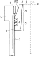
図1a〜図3には、それぞれ、本発明によるガス圧低減装置を有するシリンダ構成が、略示部分断面図によって示されている。該低減装置は、以下で全体を符号1で示すことにする。 In FIGS. 1 a to 3, a cylinder configuration having a gas pressure reducing device according to the present invention is shown by a schematic partial sectional view, respectively. The reduction device will be denoted generally by the reference numeral 1 below.
図1a〜図3に示したすべての実施例は、本発明の低減装置1,100は別にして、自体公知の往復動機関を示し、本明細書の場合の特定の例として2サイクル・クロスヘッド大型ディーゼル機関を示す。該機関は、ピストン2が配置されたシリンダ4を備え、ピストン2は、リング区域21に3個のピストンリングから成るピストンリング・パッケージ22を備えている。言うまでもなく、パッケージ22のリング数は3個より多くても少なくてもよい。図では、燃焼室3側のピストンヘッド23の下方に配置されたピストンリング・パッケージ22には、作動時、ガス圧Pが作用する。このガス圧Pは、ピストン2の圧縮行程時、つまり燃焼混合気の点火時に燃焼室3内に発生する。ピストン2は、作動時に公知形式でシリンダ4の縦軸線Lに沿って往復動できるように配置され、これによって、ピストンヘッド23は、運動時、シリンダ壁41に設けられた燃焼残渣の掻き落とし装置5と上死点OT近くで協働する。
All the embodiments shown in FIGS. 1a to 3 show a reciprocating engine known per se, apart from the reduction device 1,100 of the present invention, a two-cycle cross as a specific example in the present case. Indicates a head large diesel engine. The engine comprises a
本発明によれば、従来技術と異なり、切り欠き100の形式で低減装置1が構成され備えられることによって、低減装置に付着する燃焼残渣を制御することができ、ピストンヘッド23が上死点OT近くで掻き落とし装置5と協働することにより、ピストンリング・パッケージ22に作用するガス圧Pが自動的に調整される。この場合、掻き落とし装置5はアンチポリッシング・リング5である。
本発明のこの全般的な原理は、すべての実施例に妥当するものであり、図1a〜図3に示すように、異なる実施例に実現されている。
According to the present invention, unlike the prior art, the reduction device 1 is configured and provided in the form of the notch 100, whereby the combustion residue adhering to the reduction device can be controlled, and the
This general principle of the invention is applicable to all embodiments and is implemented in different embodiments, as shown in FIGS.
図1aでは、本発明による低減装置1が、縦軸線Lを中心として螺旋状に周回する溝100の形式で構成されている。図1aには、補修後のシリンダ4の最初の稼働前の状態が示されている。したがって、ピストンヘッド23と、螺旋状溝100を備えた掻き落とし装置5とのいずれにも燃焼残渣6は付着していない。
In FIG. 1 a, the reduction device 1 according to the invention is configured in the form of a groove 100 that spirals around a longitudinal axis L. FIG. 1a shows a state before the first operation of the
図1bは、図1aのシリンダ構成の一定作動時間後の状態を示している。この図から明瞭に分かるように、取り外し可能な掻き落としリング5には、明らかに燃焼残渣6が付着している。この場合、焼残燃渣6は、ピストン2の往復運動時、リング5がピストンヘッド23と協働することにより上死点OT近くでピストンヘッド23に対向するリング表面に形成され、それにより燃焼残渣6の表面が、多少の差はあれピストンヘッド23の対応表面と形状接続式に協働する。これにより、一方では、掻き落としリング5/ピストンヘッド間に最適シール効果が生じる。他方では、この最適シール効果は、例えば負荷変動及び/又は温度変動に基づくピストンヘッド23の外径及び/又は掻き落としリング5の内径の変化時にも維持される。掻き落としリング5とピストンヘッド23との間隔が、例えば時と共に拡大した場合には、より多くの燃焼残渣6が付着することで間隙は再び閉じられる。これに対し、ピストンヘッド23と掻き落としリング5との間隔が狭まった場合には、掻き落としリング5に付着した比較的軟質の残渣表面に沿ったピストンヘッド23の掻き落とし運動により、まさに狭まった分の燃焼残渣が削剥され、再び最適間隔に調整される。
FIG. 1b shows the state after a certain operating time of the cylinder configuration of FIG. 1a. As can be clearly seen from this figure, the
その場合、明らかに確認できる点は、図1aに示したような、低減装置1,100に未だ燃焼残渣6が未だ付着していない場合でも、ピストンヘッド23と掻き落としリング5との間のシール作用は、従来技術に比して既に著しく改善される点である。これは、周回溝100がラビリンス・シールとして作用し、それだけで既にピストンリング・パッケージ22への圧力が著しく低減されるからである。
In this case, the point that can be clearly confirmed is that the seal between the
図2a及び図2bの実施例は、図1a及び図1bの実施例とは、本発明による低減装置1が、掻き落とし装置5にではなく、ピストンヘッド23に設けられている点で異なっている。この場合、切り欠き100は、螺旋状に周回する溝の形式でではなく、多少の差はあれ一様に分配された切り欠き100の形式に構成され、例えば小さい凹部の形式で、ピストンヘッド23の表面にわたって分配される。
このため、燃焼残渣6は主としてピストンヘッド23に付着する。これにより得られるシール効果は、完全に図1a及び図1bの実施例の場合に類似している。
The embodiment of FIGS. 2a and 2b differs from the embodiment of FIGS. 1a and 1b in that the reduction device 1 according to the invention is provided not on the
For this reason, the
図3は、本発明の極めて特殊な実施例を示している。この実施例の場合、掻き落としリング5とピストンヘッド23との双方に切り欠き100の形式の本発明による低減装置1,100が設けられている。この場合、ピストンヘッド23には、取り外し可能なピストンヘッド・リング7が配置されているため、例えば、ピストンヘッド3の低減装置1,100が摩耗した場合にも、ピストン2全体を交換する必要はなく、リング7を交換するだけでよい。図3の場合、シリンダ構造物は未だ作動していない。したがって、燃焼残渣も未だ付着していない。作動状態では、燃焼残渣が次第にピストンヘッド23と掻き落としリング5の双方に付着して、最終的に形状接続式のシールが形成される。
FIG. 3 shows a very specific embodiment of the invention. In this embodiment, both the
図3の実施例は、特に、燃焼残渣の付着が比較的少ない用途に適している。この場合、ピストンヘッド23と掻き落としリング5との双方に形成されるラビリンス・シールの作用が2重に特に効果的に発揮されることで、あまり燃焼残渣が付着しなくとも、従来技術に比較してピストンヘッド23と掻き落としリング5との間のシール効果は、著しく改善される。
The embodiment of FIG. 3 is particularly suitable for applications where there is relatively little adhesion of combustion residues. In this case, the action of the labyrinth seal formed on both the
図4a〜図4cには、本発明の特に好適な3実施例が示されている。
既述のように、本発明にとって、利点として重要な点は、シリンダ4、つまり掻き落とし装置5又は低減装置1と、ピストンヘッド23との間の断面(間隔)が変化する点である。
停止温度でのシリンダを示す図4a〜図4cから特によく分かるように、構成部材である掻き落とし装置5又は低減装置1とピストンヘッド23とは、特に冷間状態では互いに平行にならないように構成されている。その場合、掻き落とし装置5又は低減装置1とピストンヘッド23とは、例えば球形、波形、段状のいずれかの形状に構成できる。
FIGS. 4a to 4c show three particularly preferred embodiments of the invention.
As described above, an important point as an advantage for the present invention is that the cross section (interval) between the
As can be seen particularly well from FIGS. 4a to 4c showing the cylinder at the stop temperature, the
ピストンヘッド23は、図4aの実施例によれば、燃焼室方向へ円錐形に先細にされた形状を有し、掻き落としリング5は、燃焼室に向かって閉じる形状を有しているが、図示されていない別の実施例では、変形傾向に応じて、逆の形状にすることもできる。
According to the embodiment of FIG. 4a, the
図4bに示した別の実施例では、言うまでもなく、2つの対向面の一方のみが変化する断面を有するようにすることができ、その場合には、ピストンヘッド23の断面を変化させるのが好ましい。
同じく既述のように、本発明の特別な利点は、構成部材が作動中に加熱されることで、切り欠き100、例えば溝100の形状に構成可能な付形部100を有する面又は有さない面が、最適形式で対向し、それによって、燃焼残渣6が付着した又は付着していない切り欠き100のラビリンス・シールにより所望のシール効果が調節される点である。
In another embodiment shown in FIG. 4b, it goes without saying that only one of the two opposing surfaces can have a varying cross section, in which case it is preferable to change the cross section of the
As also already mentioned, a particular advantage of the present invention is that a surface or surface having a shaped part 100 that can be configured in the shape of a notch 100, for example a groove 100, by heating the component during operation. The non-facing surfaces oppose in an optimal manner, whereby the desired sealing effect is adjusted by the labyrinth seal of the notch 100 with or without the
その場合、図4cに見られるように、断面(間隔)が燃焼室3へ向かって閉じられ、特に縮小している場合、燃焼残渣6なしでも良好なシールが得られる。なぜなら、最小断面が燃焼室に最も近いところに位置するからである。
これに対し、断面が、燃焼室3に向かって開き、特に拡大している場合は、燃焼残渣6が急速に付着し、この残渣の付着は、予想される温度上昇と断面の拡大に基づく。
図4a〜図4cに示した縮小する又は拡大する断面は、垂線に対し、つまりシリンダ4の縦軸線に対し約0.238°〜0.7°の角度を有するのが好ましい。
以上説明した本発明の実施例は、代表的な例と理解されるべきであり、特に既述の実施例の適宜の組み合わせすべてをも含むものである。
In that case, as can be seen in FIG. 4c, the cross section (interval) is closed towards the
On the other hand, when the cross section opens toward the
The reduced or enlarged cross section shown in FIGS. 4 a to 4 c preferably has an angle of about 0.238 ° to 0.7 ° with respect to the normal, ie with respect to the longitudinal axis of the
The embodiments of the present invention described above are to be understood as representative examples, and particularly include all appropriate combinations of the above-described embodiments.
1 ガス圧低減装置
2 ピストン
3 燃焼室
4 シリンダ
5 掻き落としリング、掻き落とし装置、アンチポリッシング・リング
6 燃焼残渣
7 ピストンヘッド・リング
21 リング区域
22 リング・パッケージ
23 ピストンヘッド
41 シリンダ壁
100 切り欠き、溝、ガス圧低減装置(1,100)
P ガス圧
DESCRIPTION OF SYMBOLS 1 Gas
P Gas pressure
Claims (15)
掻き落とし装置(5)とピストンヘッド(23)とが、停止温度時に、予め設定可能な角度(α)で少なくとも部分的に互いに傾斜するように構成かつ相互配置されており、これによって、ピストンリング・パッケージ(22)に作用するガス圧(P)が、上死点(OT)近くでピストンヘッド(23)が掻き落とし装置(5)と協働するさい、自動的に調整可能に低減されることを特徴とする、ガス圧の低減装置。 A reduction device for reducing the gas pressure (P) acting on the piston ring package (22) arranged in the ring section (21) of the piston (2) during operation of the reciprocating engine, wherein the piston (2) A piston head (23) adjacent to the ring section (21), the piston head being located on the combustion chamber side of the reciprocating engine in the assembled state, and the piston (2) in the vertical direction of the cylinder (4) in the activated state. The piston head (23) is provided on the cylinder wall (41) near the top dead center (OT) of the movement in the cylinder (4) by being arranged so as to be able to reciprocate along the axis (L). In cooperation with the scraping device (5), the combustion residue (6) is scraped off while being controlled, and the reduction device is configured in the form of a notch (100), thereby leading to the reduction device. Combustion residue of (6 In of the type deposition of is controlled,
The scraping device (5) and the piston head (23) are constructed and arranged in such a way that they are at least partly inclined with respect to each other at a presettable angle (α) at the stop temperature, whereby the piston ring The gas pressure (P) acting on the package (22) is reduced automatically and adjustable when the piston head (23) cooperates with the scraping device (5) near top dead center (OT). A gas pressure reducing device characterized by the above.
Applications Claiming Priority (1)
| Application Number | Priority Date | Filing Date | Title |
|---|---|---|---|
| EP09157367 | 2009-04-06 |
Publications (1)
| Publication Number | Publication Date |
|---|---|
| JP2010242761A true JP2010242761A (en) | 2010-10-28 |
Family
ID=40749234
Family Applications (1)
| Application Number | Title | Priority Date | Filing Date |
|---|---|---|---|
| JP2010086626A Pending JP2010242761A (en) | 2009-04-06 | 2010-04-05 | Reduction device for gas pressure applied to piston ring package of reciprocating engine |
Country Status (5)
| Country | Link |
|---|---|
| EP (1) | EP2243940A1 (en) |
| JP (1) | JP2010242761A (en) |
| KR (1) | KR20100111248A (en) |
| CN (1) | CN101858276A (en) |
| BR (1) | BRPI1000986A2 (en) |
Cited By (3)
| Publication number | Priority date | Publication date | Assignee | Title |
|---|---|---|---|---|
| JP2012154331A (en) * | 2011-01-24 | 2012-08-16 | Waertsilae Schweiz Ag | Piston for reciprocating internal combustion engine |
| JP2016520759A (en) * | 2013-06-05 | 2016-07-14 | マン・ディーゼル・アンド・ターボ・エスイー | Piston of internal combustion engine |
| CN107956594A (en) * | 2017-10-31 | 2018-04-24 | 贵阳吉利发动机有限公司 | A kind of engine structure |
Families Citing this family (6)
| Publication number | Priority date | Publication date | Assignee | Title |
|---|---|---|---|---|
| EP2602453A1 (en) * | 2011-12-07 | 2013-06-12 | Wärtsilä Schweiz AG | Piston and cylinder assembly for a reciprocating compressor combustion machine and method for removing deposits from a piston |
| CN105041470A (en) * | 2015-07-31 | 2015-11-11 | 广西玉柴机器股份有限公司 | Carbon scraping ring device for diesel engine |
| GB2546313A (en) * | 2016-01-15 | 2017-07-19 | Caterpillar Energy Solutions Gmbh | Turbulators for an internal combustion engine |
| DE102016007727A1 (en) * | 2016-06-23 | 2017-12-28 | Man Truck & Bus Ag | Internal combustion engine, in particular reciprocating internal combustion engine |
| DE102019122878A1 (en) | 2019-08-27 | 2021-03-04 | Man Energy Solutions Se | Pistons and cylinders of an internal combustion engine and internal combustion engine |
| WO2022044986A1 (en) * | 2020-08-25 | 2022-03-03 | Tpr株式会社 | Heat-shielding ring for cylinder liner, and internal combustion engine |
Family Cites Families (6)
| Publication number | Priority date | Publication date | Assignee | Title |
|---|---|---|---|---|
| US3476099A (en) * | 1968-02-26 | 1969-11-04 | Int Harvester Co | Head,gasket,and protector assembly and method |
| US4474147A (en) * | 1981-12-10 | 1984-10-02 | Mack Trucks, Inc. | Combined fire ring and carbon scraping insert |
| DE3530875A1 (en) * | 1985-08-29 | 1987-03-05 | Mak Maschinenbau Krupp | Internal combustion engine with cylinder liner spacer |
| DK174074B1 (en) * | 1995-07-07 | 2002-05-21 | Man B & W Diesel As | Combustion engine with a coke scraping ring in a cylinder |
| EP0995890A1 (en) * | 1998-10-20 | 2000-04-26 | Wärtsilä NSD Schweiz AG | Cylinder for an internal combustion engine |
| KR20070015109A (en) * | 2003-10-16 | 2007-02-01 | 가부시끼가이샤 리켄 | Internal combustion engine and liner installation ring |
-
2010
- 2010-03-09 EP EP10155915A patent/EP2243940A1/en not_active Withdrawn
- 2010-04-01 CN CN201010162715A patent/CN101858276A/en active Pending
- 2010-04-05 KR KR1020100030888A patent/KR20100111248A/en not_active Application Discontinuation
- 2010-04-05 JP JP2010086626A patent/JP2010242761A/en active Pending
- 2010-04-07 BR BRPI1000986-8A patent/BRPI1000986A2/en not_active Application Discontinuation
Cited By (3)
| Publication number | Priority date | Publication date | Assignee | Title |
|---|---|---|---|---|
| JP2012154331A (en) * | 2011-01-24 | 2012-08-16 | Waertsilae Schweiz Ag | Piston for reciprocating internal combustion engine |
| JP2016520759A (en) * | 2013-06-05 | 2016-07-14 | マン・ディーゼル・アンド・ターボ・エスイー | Piston of internal combustion engine |
| CN107956594A (en) * | 2017-10-31 | 2018-04-24 | 贵阳吉利发动机有限公司 | A kind of engine structure |
Also Published As
| Publication number | Publication date |
|---|---|
| EP2243940A1 (en) | 2010-10-27 |
| KR20100111248A (en) | 2010-10-14 |
| CN101858276A (en) | 2010-10-13 |
| BRPI1000986A2 (en) | 2012-01-24 |
Similar Documents
| Publication | Publication Date | Title |
|---|---|---|
| JP2010242761A (en) | Reduction device for gas pressure applied to piston ring package of reciprocating engine | |
| US8413632B2 (en) | Zero ridge cylinder bore | |
| CN101205849B (en) | Piston with oil collector ring | |
| RU2153089C2 (en) | Internal combustion engine with carbon scraper ring in cylinder (versions) | |
| JP6666533B2 (en) | System for controlling deposits on cylinder liners and pistons of reciprocating engines | |
| CN105221286A (en) | Engine cylinder cooling chamber | |
| JP2020106031A (en) | Piston assembly for reciprocating engine | |
| JP2009097514A (en) | Cylinder having a means of receiving lubricant | |
| KR100447455B1 (en) | Piston for two cycle engine | |
| CN102900559B (en) | For the piston of reciprocating piston type combustion engine, piston ring and distribution oil ring | |
| KR20010089772A (en) | Reciprocating piston engine | |
| RU2499899C1 (en) | Two-stroke piston diesel engine | |
| JP2001508519A (en) | Internal combustion engine piston | |
| US2513492A (en) | Engine cylinder | |
| CN203925647U (en) | A kind of internal combustion engine connection rod set and internal-combustion engine | |
| CN109751113A (en) | A kind of burning chamber of diesel engine and the method for improving burning chamber of diesel engine carbon distribution | |
| CN203925646U (en) | A kind of internal combustion engine connection rod set and internal-combustion engine | |
| Raval et al. | A Review Paper on Redesigned Piston Rings to Improve Engine Performance | |
| JP7082523B2 (en) | Heat shield film member | |
| KR101047794B1 (en) | Blow-by reduction piston and top ring structure | |
| JP2012154331A (en) | Piston for reciprocating internal combustion engine | |
| RU9280U1 (en) | PISTON SEAL | |
| MAHLE GmbH | Piston function, requirements, and types | |
| CN1182829A (en) | Single groove double-ring piston and piston ring | |
| KR19980025932U (en) | Piston structure of engine |