JP2010228690A - Vehicle dynamics control device - Google Patents
Vehicle dynamics control device Download PDFInfo
- Publication number
- JP2010228690A JP2010228690A JP2009080852A JP2009080852A JP2010228690A JP 2010228690 A JP2010228690 A JP 2010228690A JP 2009080852 A JP2009080852 A JP 2009080852A JP 2009080852 A JP2009080852 A JP 2009080852A JP 2010228690 A JP2010228690 A JP 2010228690A
- Authority
- JP
- Japan
- Prior art keywords
- vehicle
- braking
- value
- acceleration
- generated
- Prior art date
- Legal status (The legal status is an assumption and is not a legal conclusion. Google has not performed a legal analysis and makes no representation as to the accuracy of the status listed.)
- Granted
Links
- 230000001133 acceleration Effects 0.000 claims abstract description 134
- 230000033001 locomotion Effects 0.000 claims abstract description 113
- 238000001514 detection method Methods 0.000 claims description 13
- 230000008859 change Effects 0.000 abstract description 17
- 238000004364 calculation method Methods 0.000 description 56
- 238000000034 method Methods 0.000 description 33
- 238000010586 diagram Methods 0.000 description 31
- 230000007423 decrease Effects 0.000 description 17
- 230000006641 stabilisation Effects 0.000 description 10
- 238000011105 stabilization Methods 0.000 description 10
- 230000003247 decreasing effect Effects 0.000 description 8
- 230000001965 increasing effect Effects 0.000 description 6
- 238000006243 chemical reaction Methods 0.000 description 4
- 230000004043 responsiveness Effects 0.000 description 4
- 230000001172 regenerating effect Effects 0.000 description 3
- JJLJMEJHUUYSSY-UHFFFAOYSA-L Copper hydroxide Chemical compound [OH-].[OH-].[Cu+2] JJLJMEJHUUYSSY-UHFFFAOYSA-L 0.000 description 2
- 230000005540 biological transmission Effects 0.000 description 2
- 230000001771 impaired effect Effects 0.000 description 2
- 230000004044 response Effects 0.000 description 2
- 230000005484 gravity Effects 0.000 description 1
- 230000036541 health Effects 0.000 description 1
- 230000006872 improvement Effects 0.000 description 1
- 230000001939 inductive effect Effects 0.000 description 1
- 238000003825 pressing Methods 0.000 description 1
- 230000002265 prevention Effects 0.000 description 1
- 230000009467 reduction Effects 0.000 description 1
- 230000000087 stabilizing effect Effects 0.000 description 1
Images


Classifications
-
- B—PERFORMING OPERATIONS; TRANSPORTING
- B60—VEHICLES IN GENERAL
- B60W—CONJOINT CONTROL OF VEHICLE SUB-UNITS OF DIFFERENT TYPE OR DIFFERENT FUNCTION; CONTROL SYSTEMS SPECIALLY ADAPTED FOR HYBRID VEHICLES; ROAD VEHICLE DRIVE CONTROL SYSTEMS FOR PURPOSES NOT RELATED TO THE CONTROL OF A PARTICULAR SUB-UNIT
- B60W30/00—Purposes of road vehicle drive control systems not related to the control of a particular sub-unit, e.g. of systems using conjoint control of vehicle sub-units, or advanced driver assistance systems for ensuring comfort, stability and safety or drive control systems for propelling or retarding the vehicle
-
- B—PERFORMING OPERATIONS; TRANSPORTING
- B60—VEHICLES IN GENERAL
- B60T—VEHICLE BRAKE CONTROL SYSTEMS OR PARTS THEREOF; BRAKE CONTROL SYSTEMS OR PARTS THEREOF, IN GENERAL; ARRANGEMENT OF BRAKING ELEMENTS ON VEHICLES IN GENERAL; PORTABLE DEVICES FOR PREVENTING UNWANTED MOVEMENT OF VEHICLES; VEHICLE MODIFICATIONS TO FACILITATE COOLING OF BRAKES
- B60T8/00—Arrangements for adjusting wheel-braking force to meet varying vehicular or ground-surface conditions, e.g. limiting or varying distribution of braking force
- B60T8/17—Using electrical or electronic regulation means to control braking
- B60T8/1755—Brake regulation specially adapted to control the stability of the vehicle, e.g. taking into account yaw rate or transverse acceleration in a curve
-
- B—PERFORMING OPERATIONS; TRANSPORTING
- B60—VEHICLES IN GENERAL
- B60W—CONJOINT CONTROL OF VEHICLE SUB-UNITS OF DIFFERENT TYPE OR DIFFERENT FUNCTION; CONTROL SYSTEMS SPECIALLY ADAPTED FOR HYBRID VEHICLES; ROAD VEHICLE DRIVE CONTROL SYSTEMS FOR PURPOSES NOT RELATED TO THE CONTROL OF A PARTICULAR SUB-UNIT
- B60W10/00—Conjoint control of vehicle sub-units of different type or different function
- B60W10/04—Conjoint control of vehicle sub-units of different type or different function including control of propulsion units
-
- B—PERFORMING OPERATIONS; TRANSPORTING
- B60—VEHICLES IN GENERAL
- B60W—CONJOINT CONTROL OF VEHICLE SUB-UNITS OF DIFFERENT TYPE OR DIFFERENT FUNCTION; CONTROL SYSTEMS SPECIALLY ADAPTED FOR HYBRID VEHICLES; ROAD VEHICLE DRIVE CONTROL SYSTEMS FOR PURPOSES NOT RELATED TO THE CONTROL OF A PARTICULAR SUB-UNIT
- B60W10/00—Conjoint control of vehicle sub-units of different type or different function
- B60W10/18—Conjoint control of vehicle sub-units of different type or different function including control of braking systems
-
- B—PERFORMING OPERATIONS; TRANSPORTING
- B60—VEHICLES IN GENERAL
- B60W—CONJOINT CONTROL OF VEHICLE SUB-UNITS OF DIFFERENT TYPE OR DIFFERENT FUNCTION; CONTROL SYSTEMS SPECIALLY ADAPTED FOR HYBRID VEHICLES; ROAD VEHICLE DRIVE CONTROL SYSTEMS FOR PURPOSES NOT RELATED TO THE CONTROL OF A PARTICULAR SUB-UNIT
- B60W30/00—Purposes of road vehicle drive control systems not related to the control of a particular sub-unit, e.g. of systems using conjoint control of vehicle sub-units, or advanced driver assistance systems for ensuring comfort, stability and safety or drive control systems for propelling or retarding the vehicle
- B60W30/02—Control of vehicle driving stability
- B60W30/045—Improving turning performance
-
- B—PERFORMING OPERATIONS; TRANSPORTING
- B60—VEHICLES IN GENERAL
- B60T—VEHICLE BRAKE CONTROL SYSTEMS OR PARTS THEREOF; BRAKE CONTROL SYSTEMS OR PARTS THEREOF, IN GENERAL; ARRANGEMENT OF BRAKING ELEMENTS ON VEHICLES IN GENERAL; PORTABLE DEVICES FOR PREVENTING UNWANTED MOVEMENT OF VEHICLES; VEHICLE MODIFICATIONS TO FACILITATE COOLING OF BRAKES
- B60T2270/00—Further aspects of brake control systems not otherwise provided for
- B60T2270/60—Regenerative braking
- B60T2270/613—ESP features related thereto
Abstract
Description
本発明は、車両の運動状態を好適になるよう各車輪の制駆動力を制御する車両運動制御装置に関する。 The present invention relates to a vehicle motion control device that controls the braking / driving force of each wheel so that the motion state of the vehicle is suitable.
従来、自車両前方の障害物やカーブに応じてシフトダウンやブレーキ作動を自動的に行うことで、障害物との衝突回避やカーブ走行に適した速度に減速する装置が知られている(例えば特許文献1,2)。このような装置では、前方の障害物やカーブ曲率等の情報から必要な減速度を演算、実行しており、例えば路面摩擦が低い条件では、自動減速により車輪が過度にスリップする可能性がある。 2. Description of the Related Art Conventionally, there has been known a device that decelerates to a speed suitable for avoiding a collision with an obstacle or traveling on a curve by automatically performing a downshift or a brake operation according to an obstacle or a curve ahead of the host vehicle (for example, Patent Documents 1 and 2). In such a device, a necessary deceleration is calculated and executed from information such as a front obstacle and a curve curvature. For example, in a condition where the road surface friction is low, there is a possibility that the wheel slips excessively due to automatic deceleration. .
また、電気自動車やハイブリッド式の電気自動車が回生ブレーキ制御を行う場合、例えば路面摩擦が低い条件では、減速制御により車輪が過度にスリップする可能性がある。特に、後輪に電気モータを備える電気自動車が、前輪よりも後輪の制動力を大きめに制御し、後輪で回生するエネルギー量を増やそうとすると、後輪の車輪が過度にスリップし、車両運動の安定性が損なわれる恐れがある。 Moreover, when an electric vehicle or a hybrid electric vehicle performs regenerative brake control, for example, under conditions where road friction is low, wheels may slip excessively due to deceleration control. In particular, if an electric vehicle equipped with an electric motor at the rear wheel controls the braking force of the rear wheel to be larger than the front wheel and increases the amount of energy regenerated at the rear wheel, the wheel of the rear wheel slips excessively and the vehicle The stability of exercise may be impaired.
このような問題の解決手段として、これまで、車輪が過度にスリップしていると検出された際に自動減速制御を終了する方法や、車輪ロックを防止するアンチロックブレーキシステムにより減速制御を行う方法、また気温やタイヤの磨耗状態,ドライバの健康状態からスリップする危険性を推定し、発生させる減速度を補正する方法が提案されている(例えば特許文献3,4)。
As a means for solving such a problem, a method of ending automatic deceleration control when it is detected that the wheel is slipping excessively, or a method of performing deceleration control with an anti-lock brake system that prevents wheel lock In addition, a method has been proposed in which the risk of slippage is estimated from the temperature, the tire wear state, and the driver's health state, and the generated deceleration is corrected (for example,
しかしスリップにより制御を終了した場合、ドライバは急遽自分で必要な減速度を発生させることとなり、装置に対する快適性が十分であるとはいえない。また自動減速による車輪ロックをアンチロックブレーキシステムにより防止する方法では、アンチロックブレーキシステム介入直前に過スリップが発生するため、自動減速中のドライバビリティが低下する。特にカーブ前減速のように、自動減速中にドライバが操舵する場合、上述のような過スリップはドライバの操舵操作に対する車両の応答性を低下させ、操作性を悪化させる。また特許文献4に記載されたスリップ危険度を推定する方法では、様々な走行シーンに対して精度よく減速制御を行うのに膨大な情報が必要となる。 However, when the control is terminated by slipping, the driver suddenly generates the necessary deceleration by himself, and the comfort for the apparatus is not sufficient. Further, in the method of preventing the wheel lock due to the automatic deceleration by the anti-lock brake system, the overslip occurs immediately before the anti-lock brake system intervention, so that the drivability during the automatic deceleration is lowered. In particular, when the driver steers during automatic deceleration, such as pre-curve deceleration, excessive slip as described above reduces the responsiveness of the vehicle to the driver's steering operation and deteriorates operability. In addition, the method for estimating the slip risk described in Patent Document 4 requires a large amount of information for accurately performing deceleration control on various traveling scenes.
本発明は、上記のような事情に鑑みてなされたものであり、路面摩擦が変化した場合であっても、ドライバビリティを確保した自動加減速を実現する車両運動制御装置を提供することを目的とする。 The present invention has been made in view of the above circumstances, and an object of the present invention is to provide a vehicle motion control device that realizes automatic acceleration / deceleration that ensures drivability even when the road surface friction changes. And
本発明は、車両の周囲情報と、ドライバによる操作入力情報及び車両運動情報を含む車両情報のうち、前記周囲情報または前記車両情報の少なくとも一方に基づいて、少なくとも各車輪の制動トルクまたは駆動トルクの一方を制御する制駆動トルク制御を行う車両運動制御装置であって、操作入力情報には車両に横運動を発生させる横運動操作指標を含み、車両運動情報には、車両に発生する前後加速度および車両横方向の運動を表す横運動指標を含み、横運動操作指標が所定値以下、または横運動指標が所定値以下の領域において、横運動操作指標と横運動指標が比例する略線形関係となる加速度最大値を操作性確保限界加速度とし、操作性確保限界加速度を制駆動力制御により車両に発生させる加速度の上限値として、制駆動トルク制御を行う車両運動制御装置である。 The present invention provides at least braking torque or driving torque of each wheel based on at least one of the surrounding information or the vehicle information among the surrounding information of the vehicle and vehicle information including operation input information by the driver and vehicle movement information. A vehicle motion control device that performs braking / driving torque control for controlling one of the control signals, wherein the operation input information includes a lateral motion operation index that causes the vehicle to generate lateral motion, and the vehicle motion information includes the longitudinal acceleration generated in the vehicle and In a region that includes a lateral motion index that represents lateral motion of the vehicle and the lateral motion operation index is a predetermined value or less, or the lateral motion index is a predetermined value or less, a substantially linear relationship is established in which the lateral motion operation index and the lateral motion index are proportional. Braking / driving torque control with the maximum acceleration value as the maximum acceleration for ensuring operability and the maximal acceleration for operability as the upper limit of acceleration generated in the vehicle by braking / driving force control A vehicle motion control device that performs.
また本発明は、車両の周囲情報と、ドライバによる操作入力情報及び車両運動情報を含む車両情報のうち、前記周囲情報または前記車両情報の少なくとも一方に基づいて、少なくとも各車輪の制動トルクまたは駆動トルクの一方を制御する制駆動トルク制御を行う車両運動制御装置であって、操作入力情報には車輪に横力を発生させる横力操作指標を含み、車両運動情報には、車輪に発生する横力を表す車輪横力指標を含み、横力操作指標が所定値以下、もしくは車輪横力指標が所定値以下の領域において、横力操作指標と車輪横力指標が比例する略線形関係となる前後力最大値を操作性確保限界とし、操作性確保限界を、制駆動トルク制御により車両に発生させる前後力の上限値として、制駆動トルクを行う車両運動制御装置である。 Further, the present invention provides at least a braking torque or a driving torque of each wheel based on at least one of the surrounding information or the vehicle information among the surrounding information of the vehicle and vehicle information including operation input information by the driver and vehicle movement information. A vehicle motion control device that performs braking / driving torque control for controlling one of the above, wherein the operation input information includes a lateral force operation index for generating a lateral force on the wheel, and the vehicle motion information includes a lateral force generated on the wheel. In the region where the lateral force operation index is equal to or less than the predetermined value, or the lateral force force index is equal to or less than the predetermined value, the longitudinal force having a substantially linear relationship in which the lateral force operation index and the wheel lateral force index are proportional to each other. The vehicle motion control device performs braking / driving torque using the maximum value as the operability securing limit and the operability securing limit as the upper limit value of the longitudinal force generated in the vehicle by the braking / driving torque control.
本発明によれば、路面摩擦の変化によらずドライバの操作性を確保した自動加減速制御が可能となり、自動加減速制御を実施するシーンの拡張や自動加減速制御時のドライバビリティ向上に貢献することができる。 According to the present invention, automatic acceleration / deceleration control that ensures driver operability regardless of changes in road friction is possible, contributing to the expansion of scenes that implement automatic acceleration / deceleration control and the improvement of drivability during automatic acceleration / deceleration control. can do.
(制駆動力制御時の車輪前後力上限値の設定)
実施形態の説明に先立ち、理解が容易になるよう、以下、図1〜図8を用いて、本実施形態における制駆動力制御時の車輪前後力上限値に関して、その概念を説明する。
(Setting of wheel longitudinal force upper limit value during braking / driving force control)
Prior to the description of the embodiment, the concept of the wheel longitudinal force upper limit value during braking / driving force control in the present embodiment will be described below with reference to FIGS.
図1に自車両の車輪に発生する前後力Fwx,横力Fwyおよび車輪に発生可能な力の最大値である摩擦限界値|Fwmax|の関係の概念図を示す。図1に示すように、車輪に発生可能な前後力Fwx,横力Fwyの合力の最大値は、摩擦限界値|Fwmax|を半径とした円形状に近似することができ、前後力絶対値|Fwx|が大きいほど、発生可能な横力絶対値|Fwy|は減少し、前後力絶対値|Fwx|の最大値である|Fwxmax|付近では、発生可能な横力絶対値|Fwy|はほぼゼロとなる。そのため、例えばカーブ前の自動減速制御により−|Fwxmax|付近の前後力を発生させて減速している場合、カーブを旋回するのに必要な横力FwyREQを発生できない可能性がある。ここで必要な横力FwyREQを発生させるために、車輪に発生していた前後力を過度に減少させた場合、車体に発生している加速度絶対値|Gtotal|が急減し、ドライバフィーリングが悪化する。また、車輪に発生している合力の大きさのみに着目し、前後力絶対値|Fwx|を決定した場合(例えば、必要な横力絶対値|FwyREQ|と前後力絶対値|Fwx|の二乗和が、摩擦限界値|Fwmax|の二乗と一致するように発生させる前後力絶対値|Fwx|を決定)であっても、車両に横運動を発生させる操作(以下、操舵操作)に対する横力Fwyの応答性が考慮されていないため、必ずしも操舵操作に対して意図した横加速度を発生できるとは限らない。 FIG. 1 is a conceptual diagram showing the relationship between the longitudinal force Fwx and lateral force Fwy generated on the wheels of the host vehicle and the friction limit value | Fwmax | which is the maximum value of the force that can be generated on the wheels. As shown in FIG. 1, the maximum value of the resultant force of the longitudinal force Fwx and the lateral force Fwy that can be generated on the wheel can be approximated to a circular shape with the friction limit value | Fwmax | as the radius, and the absolute value of the longitudinal force | As Fwx | increases, the lateral force absolute value | Fwy | that can be generated decreases, and in the vicinity of | Fwxmax |, which is the maximum value of the longitudinal force absolute value | Fwx |, the possible lateral force absolute value | Fwy | It becomes zero. Therefore, for example, when the vehicle is decelerating by generating a longitudinal force in the vicinity of − | Fwxmax | by the automatic deceleration control before the curve, there is a possibility that the lateral force FwyREQ necessary for turning the curve cannot be generated. Here, if the longitudinal force generated on the wheel is excessively reduced to generate the necessary lateral force FwyREQ, the acceleration absolute value | Gtotal | generated on the vehicle body rapidly decreases and the driver feeling deteriorates. To do. Further, when the absolute value of the longitudinal force | Fwx | is determined by paying attention only to the magnitude of the resultant force generated on the wheel (for example, the square of the required lateral force absolute value | FwyREQ | and the longitudinal force absolute value | Fwx |) Even if the sum is the absolute value of the longitudinal force | Fwx | generated to coincide with the square of the frictional limit value | Fwmax |), the lateral force with respect to the operation that causes the vehicle to generate lateral motion (hereinafter referred to as the steering operation) Since the responsiveness of Fwy is not taken into consideration, the intended lateral acceleration for the steering operation cannot always be generated.
本実施形態では、車体に発生している加速度絶対値|Gtotal|を急減させることなく、更に操舵操作に対する横力Fwyの応答性も考慮した制駆動力制御量を決定する。 In the present embodiment, the braking / driving force control amount is determined in consideration of the responsiveness of the lateral force Fwy to the steering operation without rapidly decreasing the acceleration absolute value | Gtotal | generated in the vehicle body.
はじめに、車輪に発生する横力Fywの変化に寄与する要因について検討する。車輪に発生する横力Fywの時間変化は、車輪スリップ率sw,車輪横すべり角βw,車輪荷重Wwにより変化し、以下の式で与えられる。 First, the factors contributing to the change in the lateral force Fyw generated on the wheel will be examined. The time change of the lateral force Fyw generated on the wheel varies depending on the wheel slip rate sw, the wheel side slip angle βw, and the wheel load Ww, and is given by the following equation.

ここでFwyとβwが略線形関係(∂Fwy/∂βwがほぼ一定)で、また、横すべり角変化に対する車輪荷重Wwの変化(dWw/dβw)が小さい領域を考え、両辺にdt/dβwを積算すると、数1は以下の式に置き換えることができる。なお車輪横すべり角βwはその方向によって正もしくは負の値で表されるが、ここではその大きさに着目し、絶対値の形で検討を進める。 Here, considering a region where Fwy and βw are in a substantially linear relationship (∂Fwy / ∂βw is substantially constant) and the change in wheel load Ww with respect to the side slip angle change (dWw / dβw) is small, dt / dβw is integrated on both sides. Then, Equation 1 can be replaced with the following equation. Note that the wheel side slip angle βw is expressed as a positive or negative value depending on its direction. Here, attention is paid to the magnitude of the wheel side slip angle βw, and the examination proceeds in the form of an absolute value.
上述の数2に示すように、車輪横すべり角絶対値|βw|に対する横力絶対値|Fwy|の変化量は車輪スリップ率swにより変化することがわかる。車輪の前後力絶対値|Fwx|が非常に小さい場合、すなわち車輪スリップ率swが非常に小さい領域では、上述の式(2)の第二項(∂Fwy/∂sw・dsw/dβw)がほぼゼロとなり、|Fwy|は|βw|のみによって変化する。しかし、車輪の前後力絶対値|Fwx|の増加と共に、車輪スリップ率swが増加すると、上述の式(2)における第二項(∂Fwy/∂sw・dsw/dβw)の影響が無視できなくなる。ここでこの第二項(∂Fwy/∂sw・dsw/dβw)の∂Fwy/∂swと∂sw/∂βwについて検討を行う。
As shown in
車輪スリップ率swと横力絶対値|Fyw|の関係を図2(a)に示すように二次近似で与えると、∂Fwy/∂swとswの関係は図2(b)に示すように、線形的に単調減少する形で与えられる。これから、前後力絶対値|Fwx|が発生している場合、∂Fwy/∂swは負の値となり、前後力絶対値|Fwx|の増加につれてその値は減少することがわかる。 When the relationship between the wheel slip ratio sw and the lateral force absolute value | Fyw | is given by a quadratic approximation as shown in FIG. 2A, the relationship between ∂Fwy / ∂sw and sw is as shown in FIG. , Given in a linearly monotonically decreasing form. From this, it can be seen that when the longitudinal force absolute value | Fwx | is generated, ∂Fwy / ∂sw becomes a negative value, and the value decreases as the longitudinal force absolute value | Fwx | increases.
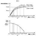
次に∂sw/∂βwについて検討するにあたり、図3(a)に前後力絶対値|Fxw|を車輪スリップ率sw、横すべり角絶対値|βw|の関係の概念図を示す。図3(a)に示すように、車輪スリップ率swと前後力絶対値|Fxw|は、車輪スリップ率swの小さい領域では、略線形関係となっているが、前後力最大値|Fwxmax|となる車輪スリップ率sw_max付近では、非線形関係となっている。また横すべり角絶対値|βw|が|βw0|から|βw1|へと増加した場合、同じ前後力絶対値|Fwx|に対して、車輪スリップ率swは増加する傾向を示す。この時の増加量は、前後力絶対値|Fxw|が大きいほど、大きな値となる。例えば図3(a)に示す前後力絶対値|Fwx_a|,|Fwx_b|(|Fwx_a|<|Fwx_b|)において、横すべり角絶対値|βw|が|βw0|から|βw1|へと増加した場合、|Fwx_a|を発生させ続ける時の車輪スリップ率変化量|Δsw_a|よりも、|Fwx_b|を発生させ続ける時の車輪スリップ率変化量|Δsw_b|は大きくなる。このように前後力絶対値|Fwx|が小さい領域、すなわち車輪スリップ率swが小さい領域よりも、前後力絶対値|Fwx|が大きい領域、すなわち車輪スリップ率swが大きい領域では、横すべり角絶対値|βw|が増加した時の車輪スリップ率変化量Δswが大きい。特に車輪スリップ率swに対する前後力絶対値|Fxw|の非線形性が強くなるほど、横すべり角絶対値|βw|が増加した時の車輪スリップ率変化量Δswは増大する。これより、車輪スリップ率swに対する∂sw/∂βwは、図3(b)のように表される。 Next, in examining ∂sw / ∂βw, FIG. 3A shows a conceptual diagram of the relationship between the longitudinal force absolute value | Fxw |, the wheel slip ratio sw, and the side slip angle absolute value | βw |. As shown in FIG. 3A, the wheel slip rate sw and the absolute value | Fxw | are substantially linear in a region where the wheel slip rate sw is small, but the maximum longitudinal force | Fwxmax | In the vicinity of the wheel slip ratio sw_max, a non-linear relationship is established. When the side slip angle absolute value | βw | increases from | βw0 | to | βw1 |, the wheel slip ratio sw tends to increase with respect to the same longitudinal force absolute value | Fwx |. The amount of increase at this time increases as the longitudinal force absolute value | Fxw | increases. For example, in the longitudinal force absolute values | Fwx_a |, | Fwx_b | (| Fwx_a | <| Fwx_b |) shown in FIG. 3A, the side slip angle absolute value | βw | increases from | βw0 | to | βw1 | , | Fwx_a |, the wheel slip ratio change amount | Δsw_b | when generating | Fwx_b | is larger than the wheel slip ratio change amount | Δsw_a | when generating | Fwx_a |. As described above, in the region where the longitudinal force absolute value | Fwx | is larger than the region where the longitudinal force absolute value | Fwx | is small, that is, the region where the wheel slip rate sw is small, that is, the region where the wheel slip rate sw is large, the absolute value of the side slip angle. The wheel slip ratio change amount Δsw when | βw | increases is large. In particular, as the nonlinearity of the longitudinal force absolute value | Fxw | with respect to the wheel slip rate sw increases, the wheel slip rate change amount Δsw when the side slip angle absolute value | βw | increases increases. Accordingly, ∂sw / ∂βw with respect to the wheel slip rate sw is expressed as shown in FIG.
以上のことから、上述の式(2)における第二項(∂Fwy/∂sw・dsw/dβw)は、車輪スリップ率swの増加にともなって負の方向に増加する。そのため、dFwy/dβwは、図4に示すように、車輪スリップ率swの増加にともない減少し、特に車輪スリップ率sw_max付近では、急激に減少する。dFwy/dβwの減少は、車輪横すべり角βwを増加させた際に発生する横力Fwyの増加量が小さくなることを意味しており、操舵に対して横加速度応答が低下する一因となる。 From the above, the second term (∂Fwy / ∂sw · dsw / dβw) in the above equation (2) increases in the negative direction as the wheel slip ratio sw increases. Therefore, as shown in FIG. 4, dFwy / dβw decreases as the wheel slip rate sw increases, and rapidly decreases particularly near the wheel slip rate sw_max. The decrease in dFwy / dβw means that the amount of increase in the lateral force Fwy generated when the wheel side slip angle βw is increased is reduced, which contributes to a decrease in the lateral acceleration response to steering.
例えば図5(a)に示すように、前後力絶対値|Fwx_c|,前後力絶対値|Fwx_d|を発生させている車輪の横すべり角絶対値|βw|をゼロから|βw2|,|βw3|と増加させた場合、車輪スリップ率は、前後力絶対値|Fwx_c|の場合はそれぞれsw_c1,sw_c2,sw_c3、前後力絶対値|Fwx_d|の場合はそれぞれsw_d1,sw_d2,sw_d3と変化する。この時、dFwy/dβwは、図5(b)に示すように、前後力絶対値|Fwx_c|ではその減少量が小さいものの、前後力絶対値|Fwx_d|の場合では、その減少量が非常に大きい。これは、図6(a)に示すように、横すべり角絶対値|βw|がゼロの時を時間t=0とし、t=t2の時に|βw|=|βw2|,t=t3の時に|βw|=|βw3|と変化させた場合、|Fwx|=0,|Fwx|=|Fwx_c|,|Fwx|=|Fwx_d|で発生する横力絶対値|Fyw|はそれぞれ図6(b)のように変化する。このように同じ横すべり角絶対値|βw|であっても、前後力絶対値|Fwx|の大きさで、発生する横力絶対値|Fwy|が大きく異なり、特に車輪スリップ率に対して前後力が非線形的に変化する領域では、前後力がない条件と比較して、発生する横力絶対値|Fwy|が非常に小さくなる。上述の図5,図6に示した、前後力絶対値|Fwx|=|Fwx_d|のような条件では、操舵開始直後から操舵変化に対する横加速度の応答が悪化するため、ドライバに強い違和感を与える。更にドライバの過操舵を誘発することで、車両運動を不安定にさせる可能性がある。ここで前後力絶対値|Fwx|=|Fwx_d|となっている状態から横すべり角を増加させる際、車輪にかける制駆動トルクを横すべり角の増加に応じて減少させることで、車輪スリップ率の増加を抑制し、発生する横力絶対値|Fwy|を増加させることができる。しかし車輪スリップ率に対して前後力絶対値|Fwx|が非線形的に変化する領域では、横すべり角の増加に対して高精度の制駆動トルク制御が必要となり、制駆動トルクを発生させるアクチュエータの性能によっては、意図した横力絶対値|Fwy|の増加を実現することが困難である。また車輪スリップ率に対して前後力絶対値|Fwx|が強い非線形性を有する領域では、意図した横力絶対値|Fwy|の増加を実現するように制駆動トルクを減少させることで、発生していた前後力絶対値|Fwx|が過度に減少する可能性がある。この時、横加速度絶対値|Gy|の増加以上に前後加速度絶対値|Gx|が減少し、その結果、車両に発生している加速度合計値|Gtotal|が減少することで、乗り心地を悪化させ、更に操舵直後に前後加速度が急減することにより操作性が低下する。 For example, as shown in FIG. 5A, the absolute value of the side slip angle | βw | of the wheel generating the absolute value of the longitudinal force | Fwx_c | and the absolute value of the longitudinal force | Fwx_d | is changed from zero to | βw2 | In the case of the absolute value of the longitudinal force | Fwx_c |, the wheel slip ratio changes as sw_c1, sw_c2, and sw_c3, respectively, and in the case of the absolute value of the longitudinal force | Fwx_d | At this time, as shown in FIG. 5B, dFwy / dβw has a small decrease in the longitudinal force absolute value | Fwx_c |, but in the case of the longitudinal force absolute value | Fwx_d | large. As shown in FIG. 6 (a), when the side slip angle absolute value | βw | is zero, time t = 0, and when t = t2, | βw | = | βw2 |, t = t3 When βw | = | βw3 | is changed, | Fwx | = 0, | Fwx | = | Fwx_c |, | Fwx | = | Fwx_d | It changes as follows. Thus, even if the same side slip angle absolute value | βw | is large, the generated lateral force absolute value | Fwy | differs greatly depending on the magnitude of the longitudinal force absolute value | Fwx |. In a region where the force changes nonlinearly, the generated lateral force absolute value | Fwy | becomes very small as compared with a condition where there is no longitudinal force. 5 and FIG. 6 described above, the longitudinal force absolute value | Fwx | = | Fwx_d |, the lateral acceleration response to the steering change is deteriorated immediately after the start of steering. . Furthermore, by inducing oversteering of the driver, there is a possibility that the vehicle motion becomes unstable. Here, when the side slip angle is increased from the state where the longitudinal force absolute value | Fwx | = | Fwx_d |, the braking / driving torque applied to the wheel is decreased according to the increase of the side slip angle, thereby increasing the wheel slip ratio. Can be suppressed, and the generated lateral force absolute value | Fwy | can be increased. However, in the region where the longitudinal force absolute value | Fwx | changes nonlinearly with respect to the wheel slip ratio, high-precision braking / driving torque control is required for the increase of the side slip angle, and the performance of the actuator that generates braking / driving torque is required. In some cases, it is difficult to realize an increase in the intended absolute value | Fwy |. In the region where the absolute value of the longitudinal force | Fwx | is strongly nonlinear with respect to the wheel slip ratio, it is generated by reducing the braking / driving torque so as to realize an increase in the intended absolute value of the lateral force | Fwy |. There is a possibility that the longitudinal force absolute value | Fwx | At this time, the longitudinal acceleration absolute value | Gx | decreases more than the increase in the lateral acceleration absolute value | Gy |, and as a result, the total acceleration value | Gtotal | In addition, the operability is reduced by a rapid decrease in the longitudinal acceleration immediately after steering.
以上のことから、自動加減速時に車両の操作性を確保するには、制駆動トルクを発生させるアクチュエータにより、上述の車輪横すべり角に応じた車輪スリップ率制御が、前後力絶対値|Fwx|を過度に減少させることなく可能な範囲内に、発生させる前後力を制限することで可能となる。例えば、横すべり角|βw|が|βw3|以下の範囲において、車輪横すべり角βwに対する横力Fwyの変化量であるdFwy/dβwを、FyBlmt以上にする場合、図7(a),(b)に示すように、dFwy/dβw=FyBlmtの時の車輪スリップ率sw_e3が、横すべり角|βw|=|βw3|の時の車輪スリップ率となるような前後力|Fwx_e|を発生させる前後力の上限値とすることで、操舵開始時に前後力を減少させることなく、操舵操作に対する横力の応答性をある一定以上確保することができる。 From the above, in order to ensure the operability of the vehicle at the time of automatic acceleration / deceleration, the wheel slip ratio control according to the wheel side slip angle described above by the actuator that generates the braking / driving torque performs the longitudinal force absolute value | Fwx | This can be achieved by limiting the longitudinal force to be generated within a possible range without excessive reduction. For example, when the side slip angle | βw | is equal to or less than | βw3 |, when dFwy / dβw, which is the amount of change in the lateral force Fwy with respect to the wheel side slip angle βw, is greater than or equal to FyBlmt, the results shown in FIGS. As shown, the upper limit value of the longitudinal force that generates the longitudinal force | Fwx_e | such that the wheel slip rate sw_e3 when dFwy / dβw = FyBlmt becomes the wheel slip rate when the side slip angle | βw | = | βw3 | By doing so, the lateral force responsiveness to the steering operation can be secured to a certain level or more without reducing the longitudinal force at the start of steering.
図8に本実施形態の概念図を示す。本実施形態では、図8に示すように、車両の加減速を自動的に行う制御において、その発生させる力を、従来のように摩擦限界を上限とするのではなく、操作性を考慮した上限値(操作性確保限界)を新たに設けたことを特徴とする。これにより自動加減速中のドライバによる車両操作性を確保すると同時に、従来の摩擦限界を上限とした制御に比べ、摩擦限界付近でのドライバの操作範囲を広げることができる。例えば図8に示すように、自動加減速制御により−|FwD|という力を発生させている場合、その状態からドライバは更に前後方向の力を発生させるか、横方向の力を発生させるかといった選択が可能となる。なお図8に示した操作性確保限界の設定方法としては、上述の図7に示した方法に限るものではない。例えば各車輪の摩擦限界を高精度に検出もしくは推定可能であれば、ある横力絶対値が発生可能な前後力絶対値の最大値を前後力の操作性確保限界としてもよい。また前後力に対するスリップ率の非線形度合いを検出可能であれば、その非線形度合いがある値以上にならないように設定した前後力を、操作性確保限界としてもよい。また車両に発生する加速度に対して、上述の図8同様に、従来の摩擦限界加速度に加え、操作性確保限界加速度を設定し、各車輪に発生する前後力を制御してもよい。例えばある横加速度絶対値を発生可能な前後加速度絶対値の最大値を操作性確保限界加速度としてもよい。操舵性確保限界の設定方法に関しては、後述の実施形態1にて説明する。 FIG. 8 shows a conceptual diagram of this embodiment. In the present embodiment, as shown in FIG. 8, in the control for automatically accelerating / decelerating the vehicle, the generated force is not limited to the friction limit as in the conventional case, but the upper limit in consideration of operability. A value (operability securing limit) is newly provided. As a result, the vehicle operability by the driver during automatic acceleration / deceleration can be ensured, and at the same time, the operation range of the driver in the vicinity of the friction limit can be expanded as compared with the conventional control with the friction limit as the upper limit. For example, as shown in FIG. 8, when a force of − | FwD | is generated by automatic acceleration / deceleration control, whether the driver further generates a longitudinal force or a lateral force from that state. Selection becomes possible. Note that the method of setting the operability securing limit shown in FIG. 8 is not limited to the method shown in FIG. For example, if the friction limit of each wheel can be detected or estimated with high accuracy, the maximum value of the absolute value of the longitudinal force that can generate a certain lateral force absolute value may be set as the operability securing limit of the longitudinal force. If the nonlinear degree of the slip ratio with respect to the longitudinal force can be detected, the longitudinal force set so that the nonlinear degree does not exceed a certain value may be set as the operability securing limit. In addition to the conventional friction limit acceleration, the operability securing limit acceleration may be set for the acceleration generated in the vehicle in addition to the conventional friction limit acceleration, and the longitudinal force generated in each wheel may be controlled. For example, the maximum value of the absolute value of longitudinal acceleration that can generate a certain lateral acceleration absolute value may be used as the operability ensuring limit acceleration. A method for setting the steering performance securing limit will be described in Embodiment 1 described later.
(発明を実施するための実施形態1)
以下、図9〜図15を用いて、本発明の第1の実施形態による車両運動制御装置の構成及び動作について説明する。
(Embodiment 1 for carrying out the invention)
Hereinafter, the configuration and operation of the vehicle motion control apparatus according to the first embodiment of the present invention will be described with reference to FIGS.
最初に、図9を用いて、本発明の第1の実施形態による車両運動制御装置の構成について説明する。 Initially, the structure of the vehicle motion control apparatus by the 1st Embodiment of this invention is demonstrated using FIG.
図9は、本発明の第1の実施形態による車両運動制御装置の構成を示すシステムブロック図である。 FIG. 9 is a system block diagram showing the configuration of the vehicle motion control device according to the first embodiment of the present invention.
本実施形態の車両運動制御装置は車両に搭載されるものであり、自車両の運動状態およびドライバによる操作量を取得する自車両情報検出手段1と、制駆動力アクチュエータ等へ制御指令を与える車両運動制御演算手段2と、車両運動制御演算手段2からの指令を基に、各車輪に制駆動トルクを発生させる車輪制駆動トルクアクチュエータ3,自車両の減速を後方車両へ報知するブレーキランプ4,外界情報取得手段5、を備える。
The vehicle motion control apparatus according to the present embodiment is mounted on a vehicle, and is a vehicle that gives a control command to a host vehicle information detection unit 1 that acquires a motion state of the host vehicle and an operation amount by a driver, and a braking / driving force actuator. Based on the command from the motion
自車両情報検出手段1には、操舵角δ,自車両の車体速度V,車体前後加速度Gx,車体横加速度Gy,車体ヨーレートr,車輪速度Vw,マスタシリンダ圧Pm,アクセルペダルストローク量などが入力する。ここで、車体速度Vの取得手段としては、各車輪の車輪速度情報から推定する手段であっても、外界センサ等を用いて直接車体速を測定する手段であってもよい。ここでドライバの操作量を取得する手段として、操舵トルクやブレーキペダルストローク量を用いてもよい。また自車両の運動状態として、更に前後加速度変化率Jx,横加速度変化率Jyが入力されてもよい。 The own vehicle information detection means 1 is inputted with a steering angle δ, a vehicle body speed V, a vehicle body longitudinal acceleration Gx, a vehicle body lateral acceleration Gy, a vehicle body yaw rate r, a wheel speed Vw, a master cylinder pressure Pm, an accelerator pedal stroke amount, and the like. To do. Here, the means for acquiring the vehicle body speed V may be a means for estimating from the wheel speed information of each wheel, or a means for directly measuring the vehicle body speed using an external sensor or the like. Here, steering torque or a brake pedal stroke amount may be used as means for acquiring the operation amount of the driver. Further, the longitudinal acceleration change rate Jx and the lateral acceleration change rate Jy may be input as the motion state of the host vehicle.
車両運動制御演算手段2は、自車両情報検出手段1により得られた操舵角δ,自車両の車体速度V,車体前後加速度Gxact,車体横加速度Gyact,車体ヨーレートr,車輪速度Vw[wheel](wheelにはFL(左前輪),FR(右前輪),RL(左後輪),RR(右前輪)がそれぞれ入る),マスタシリンダ圧Pm,アクセルペダルストローク量から、車両運動制御量を演算し、車輪制駆動トルクアクチュエータ3,ブレーキランプ4、の駆動制御量を演算する。
The vehicle motion
制駆動力トルクアクチュエータ3は、各車輪に制駆動トルクを発生させるアクチュエータであり、各車輪のブレーキディスクにブレーキパッド、もしくはドラムにシューを押付けることで制動トルクを発生させるブレーキアクチュエータであっても、エンジンにより発生したエンジントルクを、変速機を介して各車輪に伝えて駆動トルクを発生させるエンジン駆動アクチュエータであっても、モータトルクを各車輪に伝えて制駆動トルクを発生させる制駆動モータアクチュエータであってもよい。
The braking / driving
外界情報取得手段5は、自車両周囲に存在する障害物と、自車両との相対距離,相対速度,相対加速度,障害物幅,自車両進行方向のコース形状,路面状態,車線幅,自車両進路の交通信号機情報等が入力される。ここで外界情報の取得手段として、レーザレーダやミリ波センサ,カメラといった障害物認識手段を用いる方法であっても、車車間通信や路車間通信,GPSといった通信手段を用いる方法であってもよい。 The outside world information acquisition means 5 includes the relative distance, relative speed, relative acceleration, obstacle width, course shape in the traveling direction of the own vehicle, road surface condition, lane width, own vehicle. The traffic signal information of the route is input. Here, as a means for acquiring external information, a method using obstacle recognition means such as a laser radar, a millimeter wave sensor, or a camera, or a method using communication means such as inter-vehicle communication, road-to-vehicle communication, or GPS may be used. .
次に、図10〜図14を用いて、本実施形態の車両運動制御演算手段2における車輪制駆動トルクアクチュエータの制御指令演算方法について説明する。 Next, a control command calculation method for the wheel braking / driving torque actuator in the vehicle motion control calculation means 2 of the present embodiment will be described with reference to FIGS.
図10は、本発明の第1の実施形態による車両運動制御演算手段2の制御ブロック図である。 FIG. 10 is a control block diagram of the vehicle motion control calculation means 2 according to the first embodiment of the present invention.
図10に示すように、車両運動制御演算手段2は、ドライバ要求制駆動トルク演算部6,自動制駆動トルク制御演算部7,目標制駆動トルク演算部8,アクチュエータ駆動指令値演算部9、からなる。
As shown in FIG. 10, the vehicle motion
ドライバ要求制駆動トルク演算部6では、ドライバのアクセルペダル操作量やブレーキペダル操作量からドライバが要求している各車輪の制駆動トルクを演算する。例えばエンジンにより発生したエンジントルクを、変速機を介して車両前輪に駆動トルクとして与える車両であれば、アクセルペダルストローク量に応じた駆動トルクを演算する。また油圧により各車輪のブレーキパッドをブレーキディスクに押付けるブレーキアクチュエータを備えた車両であれば、ブレーキペダル操作により発生したマスタシリンダ圧やブレーキペダルストローク量に応じた各車輪のブレーキアクチュエータによる制動トルクを演算する。また制駆動モータアクチュエータにより各車輪に制駆動トルクを発生させる車両であれば、アクセルペダルストローク量に応じたモータによる駆動トルクを演算し、ブレーキペダルストローク量やマスタシリンダ圧に応じたモータによる制動トルクを演算する。
The driver requested braking / driving
自動制駆動トルク制御演算部7では、自車両情報検出手段1により得られた自車両情報、および外界情報取得手段5により得られた外界情報から、自車両に発生させる制駆動トルクを演算する。図11に自動制駆動トルク制御演算部7での制御ブロック図を示す。
The automatic braking / driving torque
図11に示すように、自動制駆動トルク制御演算部7は、目標加速度・目標ヨーモーメント演算部10,制駆動トルク増加量上限値演算部11,自動制駆動トルク指令値演算部12、からなる。
As shown in FIG. 11, the automatic braking / driving torque
目標加速度・目標ヨーモーメント演算部10では、自車両情報および外界情報から車両に発生させる加速度、もしくはヨーモーメント、もしくはその両方を演算する。
The target acceleration / target
例えばアクセルオフをトリガーとし、外界情報により得られる自車両進行方向の障害物や、カーブに応じて自車両に必要な減速度を発生させる自動加速度制御では、自車両の速度V、障害物やカーブまでの距離Ltgt,距離Ltgtの位置での目標速度Vtgtから、目標加速度Gxtgt1を以下の式で与える。 For example, in the case of an automatic acceleration control that generates the deceleration required for the host vehicle according to the curve or an obstacle in the traveling direction of the host vehicle obtained from the external world information using the accelerator off as a trigger, the speed V of the host vehicle, the obstacle or the curve From the target speed Vtgt at the distance Ltgt and the distance Ltgt, the target acceleration Gxtgt1 is given by the following equation.
ここで、自車両進行方向のカーブに対して自動加減速制御を行う場合、目標速度Vtgtはカーブをある横加速度で旋回可能なカーブ進入速度であり、また自車両進行方向の障害物に対して自動加減速制御を行う場合、目標速度Vtgtは障害物との衝突回避可能な速度(例えば障害物に対する自車両の相対速度がゼロ)とする。 Here, when the automatic acceleration / deceleration control is performed on the curve in the traveling direction of the own vehicle, the target speed Vtgt is a curve approaching speed capable of turning the curve at a certain lateral acceleration, and against an obstacle in the traveling direction of the own vehicle. When performing automatic acceleration / deceleration control, the target speed Vtgt is set to a speed at which a collision with an obstacle can be avoided (for example, the relative speed of the host vehicle with respect to the obstacle is zero).
また外界情報を用いず、操舵に応じて加減速を行う自動加減速制御では、自車両に発生する横加速度Gyから、目標加速度Gxtgt2を以下の式で与える。 In the automatic acceleration / deceleration control in which acceleration / deceleration is performed according to steering without using external information, the target acceleration Gxtgt2 is given by the following equation from the lateral acceleration Gy generated in the host vehicle.
![]()
![]()
ここで、Cxyはゲイン、Tは時定数であり、予め設定される値である。またsはラプラス演算子である。ここで横加速度Gyとして、実際に発生した車体横加速度Gyactではなく、操舵角δから推定した横加速度Gystr、もしくは車両に発生した車体ヨーレートrから推定した横加速度Gyyawを用いてもよい。 Here, Cxy is a gain, and T is a time constant, which is a preset value. S is a Laplace operator. Here, as the lateral acceleration Gy, the lateral acceleration Gystr estimated from the steering angle δ or the lateral acceleration Gyaw estimated from the vehicle body yaw rate r generated in the vehicle may be used instead of the actually generated vehicle body lateral acceleration Gyact.
また上述のGxtgt1とGxtgt2を組み合わせた値を目標加速度Gxtgt3としてもよい。 Further, a value obtained by combining the above-mentioned Gxtgt1 and Gxtgt2 may be set as the target acceleration Gxtgt3.
またヨーモーメント制御としては、例えば、外界情報により得られる自車両の走行車線と自車両の位置関係から、自車両が車線逸脱するのを防止するように自車両にヨーモーメントMzを発生させる車線逸脱防止制御であってもよい。 As the yaw moment control, for example, the lane departure that causes the own vehicle to generate the yaw moment Mz so as to prevent the own vehicle from departing from the lane based on the positional relationship between the traveling lane of the own vehicle and the own vehicle obtained from external information. Prevention control may be used.
制駆動トルク増加量上限値演算部11では、自車両情報および外界情報から制駆動トルク増加量上限値を演算する。またこの演算にあたり、外界情報は必ずしも必要ではなく、自車両情報のみで制駆動トルク増加量上限値を演算することが可能であるが、外界情報がある場合、より走行シーンに適した制駆動トルク増加量上限値の設定が可能となる。本実施例1では、外界情報がある場合の演算方法について説明する。
The braking / driving torque increase upper
外界情報により自車両に発生させる前後加速度を最大とする必要があると判定された場合、制駆動トルク増加量上限値を車輪制駆動トルクアクチュエータ3で発生可能な制駆動トルク増加量最大値を制駆動トルク増加量上限値とし、その他の場合は、操舵性確保限界に基づいて制駆動トルク増加量上限値を設定する。例えば、外界情報から自車両前方の障害物との衝突回避において、操舵による回避よりも減速による回避が優位であると判定された場合、摩擦限界での減速が可能となるよう制駆動トルク増加量上限値を設定し、逆に操舵による回避が優位である場合や、カーブ前での自動減速、上述の操舵に応じて加減速を行う自動加減速制御では、操舵性確保限界に基づいて制駆動トルク増加量上限値を設定する。
If it is determined from the external world information that the longitudinal acceleration generated in the vehicle needs to be maximized, the upper limit value of the braking / driving torque increase amount is controlled by the wheel braking /
操舵性確保限界に基づく制駆動トルク増加量上限値の設定方法としては、車輪に発生する前後力が操舵性確保限界となる前後力上限値を超えないように、制駆動トルク増加量上限値を設定する。ここで操舵性確保限界となる前後力上限値の推定方法はいくつか考えられるが、本実施例1では、各車輪のスリップ率変化に対する前後力変化(以下、スリップスティフネスSstfと呼ぶ)を用いた方法について説明する。 The braking / driving torque increase upper limit value based on the steerability securing limit is set by setting the braking / driving torque increase upper limit value so that the longitudinal force generated on the wheels does not exceed the longitudinal force upper limit value that is the steering securing securing limit. Set. Here, there are several methods for estimating the longitudinal force upper limit value that is the limit for securing the steering performance, but in the first embodiment, the longitudinal force change (hereinafter referred to as slip stiffness Sstf) with respect to the slip rate change of each wheel is used. A method will be described.
図12は車輪スリップ率と前後力絶対値、およびスリップスティフネスの関係図である。 FIG. 12 is a graph showing the relationship between the wheel slip ratio, the absolute value of the longitudinal force, and the slip stiffness.
図12(a)に示すように、車輪スリップ率と前後力絶対値は車輪スリップ率が小さい場合は略線形関係にあるが、車輪スリップ率が大きくなると前後力絶対値は車輪スリップ率に対して非線形的に変化する。そのため図12(a)に示すように、車輪スリップ率がsw0からsw2まで増加した場合、スリップスティフネスSstfは、図12(b)に示すように変化し、車輪スリップ率が小さい領域ではほぼ一定となっているが、車輪スリップ率の増加につれて減少する。つまりスリップスティフネスSstfは車輪スリップ率に対する前後力絶対値の非線形度合いが強くなるほど、その値が減少する。上述の図7に示したように、操舵性の一つの指標となるdFwy/dβwは、前後力絶対値の非線形度合いが強くなるほど減少する傾向がある。そのためこの非線形度合いの指標としてスリップスティフネスSstfを用い、スリップスティフネスSstfが所定値以上になるよう前後力上限値を設定することで、ある所定値以上のdFwy/dβwを確保することが可能である。 As shown in FIG. 12 (a), the wheel slip rate and the absolute value of the longitudinal force have a substantially linear relationship when the wheel slip rate is small, but when the wheel slip rate increases, the absolute value of the longitudinal force is relative to the wheel slip rate. Changes nonlinearly. Therefore, as shown in FIG. 12 (a), when the wheel slip rate increases from sw0 to sw2, the slip stiffness Sstf changes as shown in FIG. 12 (b), and is almost constant in a region where the wheel slip rate is small. However, it decreases as the wheel slip rate increases. That is, the slip stiffness Sstf decreases as the nonlinear degree of the absolute value of the longitudinal force with respect to the wheel slip ratio increases. As shown in FIG. 7 described above, dFwy / dβw, which is one index of steering performance, tends to decrease as the nonlinear degree of the absolute value of the longitudinal force increases. Therefore, it is possible to secure dFwy / dβw equal to or greater than a predetermined value by using the slip stiffness Sstf as an index of the nonlinear degree and setting the longitudinal force upper limit value so that the slip stiffness Sstf is equal to or greater than the predetermined value.
またスリップスティフネスとして、図12に示したような各車輪スリップ率での微分値の演算が困難である場合、図13に示すように、車輪スリップ率がゼロの時はあるスリップスティフネスSstf0を設定し、車輪スリップ率が正の領域では、原点と車輪スリップ率と前後力絶対値のなす点(例えば図13(a)のP1,P2)を結んだ直線の傾きを、スリップスティフネスとしてもよい。 As the slip stiffness, when it is difficult to calculate the differential value at each wheel slip rate as shown in FIG. 12, a certain slip stiffness Sstf0 is set when the wheel slip rate is zero as shown in FIG. In the region where the wheel slip rate is positive, the slope of a straight line connecting the origin, the wheel slip rate, and the point formed by the absolute value of the longitudinal force (for example, P1 and P2 in FIG. 13A) may be used as the slip stiffness.
以上により得られたスリップスティフネスがある所定値よりも小さくならないように、各車輪の制駆動トルク増加量上限値を設定する。図14に制動トルクTbrkの増加量上限値ΔTbrk_maxを設定する一例を示す。上述の図12,図13で得られたスリップスティフネスSstfが、図14(a)に示すある閾値Sstflmt0より小さくなった場合、図14(b)に示す制動トルク増加量上限値ΔTbrk_maxを、初期値ΔTbrk_max0からSstfの減少と共に減少させ、ある所定値Sstflmt1からSstflmt2の間ではその値をゼロとする。ここである所定値Sstflmt1からSstflmt2は、操舵性確保限界を考慮して予め設定される値である。これにより制動トルクが増加し、スリップスティフネスSstfが低下し始めると、制動トルクの増加量が減少し、ある所定値Sstflmt1より小さくなると、制動トルクの増加量がゼロとなることで、スリップスティフネスSstfがSstflmt2以上となるように制動トルクを制限することができる。またもし更にSstflmt2よりもSstfが減少した場合、制動トルク増加量上限値ΔTbrk_maxを負の値にすることで、制動トルクを減少させ、スリップスティフネスSstfを増加させることができる。ここで制動トルクを一例に説明をしたが、駆動トルクTdrvの増加量上限値ΔTdrv_maxであっても同様に設定が可能である。また図14ではスリップスティフネスSstfの減少に対して、制動トルク増加量上限値を線形的に減少させているが、スリップスティフネスSstfに対する制動トルク増加量上限値の設定方法は図14に示した方法に限らず、スリップスティフネスSstfがある所定値Sstflmt2よりも小さくならないよう制動トルク増加量上限値を設定する方法であればよい。これにより操舵性確保限界を考慮した制駆動トルク増加量上限値が設定できる。 The braking / driving torque increase upper limit value of each wheel is set so that the slip stiffness obtained as described above does not become smaller than a predetermined value. FIG. 14 shows an example of setting the increase amount upper limit value ΔTbrk_max of the braking torque Tbrk. When the slip stiffness Sstf obtained in FIGS. 12 and 13 is smaller than a certain threshold value Sstflmt0 shown in FIG. 14A, the braking torque increase upper limit ΔTbrk_max shown in FIG. ΔTbrk_max0 is decreased as Sstf is decreased, and the value is set to zero between a predetermined value Sstflmt1 and Sstflmt2. Here, the predetermined values Sstflmt1 to Sstflmt2 are values set in advance in consideration of a steering performance securing limit. As a result, when the braking torque increases and the slip stiffness Sstf starts to decrease, the amount of increase in the braking torque decreases. When the slip torque Sstf becomes smaller than a predetermined value Sstflmt1, the amount of increase in the braking torque becomes zero. The braking torque can be limited to be equal to or greater than Sstflmt2. Further, when Sstf is further decreased than Sstflmt2, the braking torque can be decreased and the slip stiffness Sstf can be increased by setting the braking torque increase upper limit ΔTbrk_max to a negative value. Although the braking torque has been described as an example here, the same setting is possible even when the increase amount upper limit value ΔTdrv_max of the drive torque Tdrv is set. Further, in FIG. 14, the braking torque increase amount upper limit value is linearly decreased with respect to the decrease of the slip stiffness Sstf, but the braking torque increase amount upper limit value for the slip stiffness Sstf is set in the method shown in FIG. Any method may be used as long as it sets the braking torque increase upper limit so that the slip stiffness Sstf does not become smaller than a predetermined value Sstflmt2. Thus, the braking / driving torque increase upper limit value can be set in consideration of the steering performance securing limit.
また上述の図14(a)に示したSstflmt0,Sstflmt1,Sstflmt2といった値や、図14(b)に示したスリップスティフネスSstfに対する制動トルク増加量上限値は、摩擦限界に応じて異なる値としてもよい。例えば摩擦限界が小さい場合は、摩擦限界が大きい場合と比較し、Sstflmt1,Sstflmt2を大きな値にしてもよい。この摩擦限界の検出、もしくは推定が必要となるが、摩擦限界の推定方法として、例えばスリップスティフネスSstfに対する前後力絶対値から、摩擦限界を推定する方法であってもよい。 Further, the above-described values such as Sstflmt0, Sstflmt1, and Sstflmt2 shown in FIG. 14A and the braking torque increase upper limit value for the slip stiffness Sstf shown in FIG. 14B may be different values depending on the friction limit. . For example, when the friction limit is small, Sstflmt1 and Sstflmt2 may be set to a larger value than when the friction limit is large. Although detection or estimation of this friction limit is required, as a friction limit estimation method, for example, a method of estimating the friction limit from the absolute value of the longitudinal force with respect to the slip stiffness Sstf may be used.
ここで上述のスリップスティフネスを演算するにあたり、各車輪に発生している前後力絶対値の検出、もしくは推定が必要となる。 Here, in calculating the slip stiffness described above, it is necessary to detect or estimate the absolute value of the longitudinal force generated in each wheel.
各車輪の前後力を検出する方法として、ホイール部のひずみ等から前後力を検出する方法であっても、車輪軸受け部のひずみ等から検出する方法であってもよい。また前後力の推定方法として、高精度なタイヤモデルを用いて前後力を推定する方法であってもよい。また、複雑なタイヤモデルや、現状高価な前後力を検出するためのセンサ等を追加することなく、現状量産されている車両の構成で容易にスリップスティフネスが演算可能となるよう、前後加速度と各車輪スリップ率からスリップスティフネスの演算を行ってもよい。例えば各車輪スリップ率Sw[wheel]と車体に発生している前後加速度Gxactから、車体を一つの車輪と考えたときのスリップスティフネス(以下車体スリップスティフネスVSstf)を、以下の式で与える。 The method of detecting the longitudinal force of each wheel may be a method of detecting the longitudinal force from the strain of the wheel portion or the like, or a method of detecting from the strain or the like of the wheel bearing portion. As a method for estimating the longitudinal force, a method for estimating the longitudinal force using a highly accurate tire model may be used. In addition, the longitudinal acceleration and each of the accelerations can be calculated so that slip stiffness can be easily calculated with the configuration of the currently mass-produced vehicle without adding a complicated tire model or a sensor for detecting the presently expensive longitudinal force. The slip stiffness may be calculated from the wheel slip rate. For example, the slip stiffness (hereinafter referred to as vehicle body slip stiffness VSstf) when the vehicle body is considered as one wheel is given by the following equation from each wheel slip ratio Sw [wheel] and the longitudinal acceleration Gxact generated in the vehicle body.
ここでMは車両質量、kwは前後力の荷重依存係数、Hは重心高さ、Lwheelbaseはホイールベース長さであり、予め設定される値である。またGxactは車両進行方向を正とした車体前後加速度,車輪スリップ率Sw[wheel]は車体速度Vおよび各車輪速度Vw[wheel]から得られる値である。 Here, M is the vehicle mass, kw is the load dependency coefficient of the longitudinal force, H is the height of the center of gravity, and Lwheelbase is the wheelbase length, which is a preset value. Gxact is a vehicle longitudinal acceleration with the vehicle traveling direction being positive, and wheel slip ratio Sw [wheel] is a value obtained from the vehicle speed V and each wheel speed Vw [wheel].
上記数5により得られた車両スリップスティフネスVSstfを用いても、いくつかの制約条件をつけることで、上述の図14同様に制駆動トルク上限値の設定が可能である。例えば4輪の制駆動トルクを制御する際、前輪左右輪、および後輪左右輪の制駆動トルクをそれぞれ同値とし、前輪二輪、もしくは後輪二輪の内、上述のVSstfがある所定値より小さくならないよう、より車輪スリップ率が大きい車輪の制駆動トルク増加上限値を設定し、他方の車輪スリップ率が前者の車輪スリップ率より大きくならないよう制駆動トルク増加上限値を設定することで、操舵性確保限界を考慮した制駆動トルク上限値の設定ができる。また摩擦限界についても同様に、車両スリップスティフネスVSstfと車両に発生している加速度絶対値から、摩擦限界の推定が可能である。
Even if the vehicle slip stiffness VSstf obtained by the
自動制駆動トルク指令値演算部12では、上述の目標加速度・目標ヨーモーメント演算部10により演算された目標加速度、もしくは目標ヨーモーメント、もしくはその両方と、制駆動トルク増加量上限値演算部11により演算された制駆動トルク増加量上限値から、自動制駆動トルク指令値を演算する。
The automatic braking / driving torque command value calculation unit 12 includes the target acceleration and / or target yaw moment calculated by the target acceleration / target yaw
上述の目標加速度・目標ヨーモーメント演算部10により演算された目標加速度、もしくは目標ヨーモーメント、もしくはその両方を発生させるために、ある車輪に発生させる自動制動トルク初期値がTbrk_vreq0[wheel]であった場合、制駆動トルク増加量上限値演算部11により演算された制動トルク増加量上限値ΔTbrk_max[wheel]から、自動制動トルク指令値Tbrk_vreq[wheel]は、以下の式で与えられる。
In order to generate the target acceleration and / or the target yaw moment calculated by the target acceleration / target yaw
ここでTbrk_vreq_z1[wheel]は、Tbrk_vreq[wheel]の前回値、min(A,B)はAとBの内、小さい方の値を選択する関数である。 Here, Tbrk_vreq_z1 [wheel] is a function that selects the previous value of Tbrk_vreq [wheel], and min (A, B) is a function that selects the smaller one of A and B.
例えば目標加速度・目標ヨーモーメント演算部10により、目標加速度−Gxtgt1という値が演算され、制駆動トルク増加量上限値演算部11により制動トルク増加量上限値として、前輪二輪がΔTbrk_maxf、後輪二輪がΔTbrk_maxrという値が演算されている場合、前輪の自動制動トルク指令値Tbrk_vreqf,後輪の自動制動トルク指令値Tbrk_vreqrはそれぞれ以下の式で演算される。
For example, the target acceleration / target yaw
ここでCFtrqfは前輪の制動トルク−制動力変換係数、CFtrqrは後輪の制動トルク−制動力変換係数であり、αGfは前後加速度制御時の前後輪の制動力配分比(0≦αGf≦1),Tbrk_vreqf_z1は前輪の制動トルク前回値,Tbrk_vreqr_z1は後輪の制動トルク前回値である。ここでαfは予め設定される固定値であっても、各車輪の摩擦限界に比例して変化する値であってもよい。 Here, CFtrqf is the braking torque-braking force conversion coefficient of the front wheels, CFtrqr is the braking torque-braking force conversion coefficient of the rear wheels, and αGf is the braking force distribution ratio of the front and rear wheels during longitudinal acceleration control (0 ≦ αGf ≦ 1). , Tbrk_vreqf_z1 is the previous value of the braking torque of the front wheel, and Tbrk_vreqr_z1 is the previous value of the braking torque of the rear wheel. Here, αf may be a preset fixed value or a value that changes in proportion to the friction limit of each wheel.
また例えば、目標加速度・目標ヨーモーメント演算部10により、目標ヨーモーメントとしてMztgt1という左回りのヨーモーメント値が演算され、制駆動トルク増加量上限値演算部11により制動トルク増加量上限値として、左前輪がΔTbrk_max[FL]、左後輪がΔTbrk_max[RL]という値が演算されている場合、前輪の制動トルク指令値Tbrk_vreq[FL],後輪の制動トルク指令値Tbrk_vreq[RL]はそれぞれ以下の式で演算される。
Further, for example, the target acceleration / target yaw
ここでCMtrqfは前輪の制動トルク−ヨーモーメント変換係数,CMtrqrは後輪の制動トルク−ヨーモーメント変換係数であり、αMfはヨーモーメント制御時の前後輪の制動力配分比(0≦αMf≦1)、ここでαMfは予め設定される固定値であっても、各車輪の摩擦限界に比例して変化する値であっても、発生させるヨーモーメントに応じて変化させる値であってもよい。 Here, CMtrqf is the braking torque-yaw moment conversion coefficient for the front wheels, CMtrqr is the braking torque-yaw moment conversion coefficient for the rear wheels, and αMf is the braking force distribution ratio of the front and rear wheels during yaw moment control (0 ≦ αMf ≦ 1). Here, αMf may be a preset fixed value, a value that changes in proportion to the friction limit of each wheel, or a value that changes according to the yaw moment to be generated.
目標制駆動トルク演算部8では、前記ドライバ要求制駆動トルク演算部6により得られたドライバ要求制駆動トルクと、前記自動制駆動トルク制御演算部7により得られた自動制駆動トルク指令値から最終的な目標制駆動トルクを演算する。
The target braking / driving
目標制駆動トルクは、ドライバ要求制駆動トルクと自動制駆動トルク指令値の加減演算することで与える方法であっても、ドライバ要求制駆動トルクと自動制駆動トルク指令値それぞれにある重み係数をつけた上で、両者を加減演算することで与える方法であってもよい。両者が同一方向(制動もしくは駆動)であれば、どちらか大きい方の値を選択する方法であっても、上述のこれらの方法を組み合わせた方法であってもよい。例えば前記ドライバ要求制駆動トルク演算部6によりドライバ要求駆動トルクTdrv_dreq[wheel]が演算され、前記自動制駆動トルク制御演算部7により自動制動トルク指令値Tbrk_vreq[wheel]が演算されている場合、最終的な目標制駆動トルクTw_tgt[wheel]を以下の式で与えてもよい。ここで目標制駆動トルクTw_tgt[wheel]は正であれば駆動トルク、負であれば制動トルクとなる値である。
The target braking / driving torque is given by calculating the addition / subtraction of the driver requested braking / driving torque and the automatic braking / driving torque command value. In addition, a method of giving both by adding and subtracting may be used. If both are in the same direction (braking or driving), either the method of selecting the larger value or the method of combining these methods may be used. For example, when the driver required driving torque Tdrv_dreq [wheel] is calculated by the driver required braking / driving
![]()
![]()
ここでWdはドライバ要求制駆動トルクに対する重み係数、Wvは自動制駆動トルク指令値に対する重み係数である。前記Wd,Wvは予め設定される値であっても、外界情報等に基づいてその値を変更してもよい。例えば自車両前方の障害物との衝突危険度が非常に高いにも関わらず、ドライバ要求駆動トルクTdrv_dreq[wheel]がある場合、Wdを非常に小さい値とし、自動制動トルク指令値Tbrk_vreq[wheel]が優先されるようにする。これにより、自車両前方の障害物との衝突危険性が高いにも関わらず、ドライバがアクセルを踏込んでしまった場合であっても、必要な減速を行うことができる。また例えば前記ドライバ要求制駆動トルク演算部6によりドライバ要求制動トルクTbrk_dreq[wheel]が演算され、前記自動制駆動トルク制御演算部7により自動制動トルク指令値Tbrk_vreq[wheel]が演算されている場合、最終的な目標制駆動トルクTw_tgt[wheel]を以下の式で与えてもよい。
Here, Wd is a weighting factor for the driver requested braking / driving torque, and Wv is a weighting factor for the automatic braking / driving torque command value. Wd and Wv may be preset values or may be changed based on external information or the like. For example, when the driver requested drive torque Tdrv_dreq [wheel] is present even though the risk of collision with an obstacle ahead of the host vehicle is very high, the automatic braking torque command value Tbrk_vreq [wheel] is set to a very small value of Wd. To be prioritized. Thereby, even if the driver has stepped on the accelerator despite the high risk of collision with an obstacle ahead of the host vehicle, the necessary deceleration can be performed. Further, for example, when the driver required braking torque Tbrk_dreq [wheel] is calculated by the driver required braking / driving
![]()
![]()
これにより、例えば自動減速中にドライバが減速不足を感じた際、Tbrk_dreq[wheel]に応じて減速度を増加させることができる。 Thereby, for example, when the driver feels that the vehicle is under deceleration during automatic deceleration, the deceleration can be increased according to Tbrk_dreq [wheel].
アクチュエータ駆動指令値演算部9では、目標制駆動トルクTw_tgt[wheel]に応じて、必要なアクチュエータの駆動制御指令値を演算する。例えば車輪制駆動トルクアクチュエータがモータである場合、目標制駆動トルクTw_tgt[wheel]を発生させるようモータの駆動指令値を演算する。またこの時目標制駆動トルクTw_tgt[wheel]が負、すなわち制動トルクを発生させる場合、発生させる減速度に応じてブレーキランプを点灯するようにブレーキランプ駆動指令を演算する。例えば発生させる減速度が非常に小さい場合、ブレーキランプは点灯させず、ある所定値以上の減速度を発生させる場合にのみブレーキランプを点灯させるようにしてもよい。 The actuator drive command value calculation unit 9 calculates a required actuator drive control command value according to the target braking / driving torque Tw_tgt [wheel]. For example, when the wheel braking / driving torque actuator is a motor, the motor driving command value is calculated so as to generate the target braking / driving torque Tw_tgt [wheel]. At this time, when the target braking / driving torque Tw_tgt [wheel] is negative, that is, when braking torque is generated, a brake lamp driving command is calculated so that the brake lamp is turned on according to the deceleration to be generated. For example, when the deceleration to be generated is very small, the brake lamp may not be turned on, and the brake lamp may be turned on only when a deceleration greater than a predetermined value is generated.
以上のように、本実施形態では、従来の摩擦限界のみを考えた車輪制駆動トルク制御のみではなく、操舵性確保限界を上限値とした制駆動トルク制御を行うことで、車両に発生する加速度絶対値の過度な減少を抑えながら自動制駆動トルク制御中の操舵性を確保することが可能となる。 As described above, in the present embodiment, not only the wheel braking / driving torque control considering only the conventional friction limit, but also the acceleration generated in the vehicle by performing the braking / driving torque control with the steering performance securing limit as the upper limit value. It is possible to ensure the steering performance during the automatic braking / driving torque control while suppressing an excessive decrease in the absolute value.
本実施形態では、スリップスティフネスを用いて制駆動トルク増加量上限値の設定する方法を説明したが、車両に発生可能な摩擦限界を精度よく検出、もしくは推定可能であれば、摩擦限界よりも小さな値となる操作性確保限界を設定し、操作性確保限界に基づいて各車輪の制駆動トルクを設定する方法であってもよい。この方法では、摩擦限界に応じた操作性確保限界を予め設定することで可能となる。 In this embodiment, the method of setting the braking / driving torque increase upper limit value using slip stiffness has been described. However, if the friction limit that can be generated in the vehicle can be accurately detected or estimated, it is smaller than the friction limit. A method may be used in which a operability securing limit is set and a braking / driving torque of each wheel is set based on the operability securing limit. This method is possible by setting in advance a operability securing limit corresponding to the friction limit.
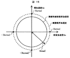
また車両に発生する加速度に基づいて各車輪の制駆動トルクを設定する方法であってもよい。例えば加速度摩擦限界加速度を精度よく検出、もしくは推定可能であれば、図15に示すように摩擦限界加速度よりも小さな値となる操作性確保限界加速度を設定し、操作性確保限界加速度に基づいて各車輪の制駆動トルクを設定する方法であってもよい。この方法では、摩擦限界加速度に応じた操作性確保限界加速度を予め設定することで可能となる。 Moreover, the method of setting the braking / driving torque of each wheel based on the acceleration which generate | occur | produces in a vehicle may be sufficient. For example, if it is possible to accurately detect or estimate the acceleration friction limit acceleration, as shown in FIG. 15, the operability securing limit acceleration that is smaller than the friction limit acceleration is set, and each operability securing limit acceleration is set based on the operability securing limit acceleration. A method of setting the braking / driving torque of the wheel may be used. In this method, it becomes possible by presetting the operability ensuring limit acceleration according to the friction limit acceleration.
(発明を実施するための実施形態2)
以下、図16,図17を用いて、本発明の第2の実施形態による車両運動制御装置の構成及び動作について説明する。
(
Hereinafter, the configuration and operation of the vehicle motion control apparatus according to the second embodiment of the present invention will be described with reference to FIGS. 16 and 17.
最初に、図16を用いて、本発明の第2の実施形態による車両運動制御装置の構成について説明する。 Initially, the structure of the vehicle motion control apparatus by the 2nd Embodiment of this invention is demonstrated using FIG.
図16は、本発明の第2の実施形態による車両運動制御装置の構成を示すシステムブロック図である。 FIG. 16 is a system block diagram showing the configuration of the vehicle motion control device according to the second embodiment of the present invention.
本実施形態の車両運動制御装置は車両に搭載されるものであり、自車両の運動状態およびドライバによる操作量を取得する自車両情報検出手段1と、制駆動力アクチュエータ等へ制御指令を与える車両運動制御演算手段2′と、車両運動制御演算手段2′からの指令を基に、各車輪に制駆動トルクを発生させる車輪制駆動トルクアクチュエータ3,自車両の減速を後方車両へ報知するブレーキランプ4,外界情報取得手段5、を備える。
The vehicle motion control apparatus according to the present embodiment is mounted on a vehicle, and is a vehicle that gives a control command to a host vehicle information detection unit 1 that acquires a motion state of the host vehicle and an operation amount by a driver, a braking / driving force actuator, and the like. Based on commands from the motion control calculation means 2 'and the vehicle motion control calculation means 2', a wheel braking /
ここで自車両情報検出手段1,車輪制駆動トルクアクチュエータ3,ブレーキランプ4,外界情報取得手段5、については上述の第1の実施形態と同様であるため、説明は省略し、車両運動制御演算手段2′における車輪制駆動トルクアクチュエータの制御指令演算方法について説明する。
Here, the vehicle information detection means 1, the wheel braking /
図17は、本発明の第2の実施形態による車両運動制御演算手段2′の制御ブロック図である。
FIG. 17 is a control block diagram of the vehicle motion
図17に示すように、車両運動制御演算手段2′は、ドライバ要求制駆動トルク演算部6,自動制駆動トルク制御演算部7,目標制駆動トルク演算部8,アクチュエータ駆動指令値演算部9,車両挙動安定化制駆動トルク補正制御演算部13,摩擦限界制駆動トルク補正制御演算部14からなる。
As shown in FIG. 17, the vehicle motion control calculating means 2 'includes a driver requested braking / driving
ここで、ドライバ要求制駆動トルク演算部6,自動制駆動トルク制御演算部7,目標制駆動トルク演算部8,アクチュエータ駆動指令値演算部9は、上述の第1の実施形態と同様であるため、説明は省略する。
Here, the driver requested braking / driving
車両挙動安定化制駆動トルク補正制御演算部13では、自車両情報検出手段1により得られた自車両情報から、車両挙動を安定化させるのに必要なヨーモーメントMzreq、もしくは車体加速度Gxreq、もしくはその両方を演算し、前記MzreqおよびGxreqに基づいて、目標制駆動トルク演算部8により演算された各車輪の目標制駆動トルクを補正し、車両挙動安定化補正目標制駆動トルクを演算する。
In the vehicle behavior stabilization braking / driving torque correction
例えば車両に発生しているヨーレートr、および発生している横加速度Gyact、および操舵角δに基づいて、車両のスピンアウト傾向を検出した場合、スピンアウトを抑制する方向のヨーモーメントを発生させるよう前記目標制駆動トルクを補正する。また同様に車両のドリフトアウト傾向を検出した場合、ドリフトアウトを抑制するヨーモーメント、および減速度を発生させるよう、前記目標制駆動トルクを補正する。 For example, when a vehicle spin-out tendency is detected based on the yaw rate r generated in the vehicle, the lateral acceleration Gyact generated, and the steering angle δ, a yaw moment in a direction to suppress the spin-out is generated. The target braking / driving torque is corrected. Similarly, when a vehicle drift-out tendency is detected, the target braking / driving torque is corrected so as to generate a yaw moment and a deceleration that suppress drift-out.
摩擦限界制駆動トルク補正制御演算部14では、自車両情報検出手段1により得られた自車両情報から、各車輪のロック傾向やホイールスピン傾向を検出し、車両挙動安定化制駆動トルク補正制御演算部10により演算された車両挙動安定化補正目標制駆動トルクを補正し、摩擦限界補正目標制駆動トルクを演算する。
The friction limit braking / driving torque correction
以上のように、制駆動トルク増加量上限値演算部11により車輪に発生させる前後力絶対値を図8に示した操舵性確保限界以下とする制御に加え、車両挙動安定化制駆動トルク補正制御演算部13および摩擦限界制駆動トルク補正制御演算部14を行うことで、通常運転時の操作性を確保した制駆動トルク制御に加え、車両の挙動が不安定になった際の安定化制御や摩擦限界での制駆動トルク制御が可能となる。これにより、例えば操舵性確保限界での自動制動トルク制御中にドライバが自動制動トルク以上の制動トルクを発生させようとした場合であっても、車輪ロックを発生させることなく、摩擦限界内での制動トルクを発生させることができる。
As described above, the vehicle behavior stabilization braking / driving torque correction control is performed in addition to the control for setting the absolute value of the longitudinal force generated on the wheels by the braking / driving torque increase upper
(発明を実施するための実施形態3)
以下、図18〜図20を用いて、本発明の第3の実施形態による車両運動制御装置の構成及び動作について説明する。
(
Hereinafter, the configuration and operation of the vehicle motion control device according to the third embodiment of the present invention will be described with reference to FIGS.
最初に、図18を用いて、本発明の第3の実施形態による車両運動制御装置の構成について説明する。 Initially, the structure of the vehicle motion control apparatus by the 3rd Embodiment of this invention is demonstrated using FIG.
図18は、本発明の第3の実施形態による車両運動制御装置の構成を示すシステムブロック図である。 FIG. 18 is a system block diagram showing the configuration of the vehicle motion control device according to the third embodiment of the present invention.
本実施形態の車両運動制御装置は車両に搭載されるものであり、自車両の運動状態およびドライバによる操作量を取得する自車両情報検出手段1と、制駆動力アクチュエータ等へ制御指令を与える車両運動制御演算手段2″と、車両運動制御演算手段2″からの指令を基に、各車輪に制駆動トルクを発生させる車輪制駆動トルクアクチュエータ3,自車両の減速を後方車両へ報知するブレーキランプ4,要求加速度検出手段12、を備える。
The vehicle motion control apparatus according to the present embodiment is mounted on a vehicle, and is a vehicle that gives a control command to a host vehicle information detection unit 1 that acquires a motion state of the host vehicle and an operation amount by a driver, a braking / driving force actuator, and the like. Based on commands from the motion control calculation means 2 "and the vehicle motion control calculation means 2", a wheel braking /
ここで自車両情報検出手段1,車輪制駆動トルクアクチュエータ3,ブレーキランプ4、については上述の第1の実施形態と同様であるため、説明は省略し、要求加速度検出手段12、および車両運動制御演算手段2″における車輪制駆動トルクアクチュエータの制御指令演算方法について説明する。
Here, since the own vehicle information detecting means 1, the wheel braking /
要求加速度検出手段12はドライバによる要求加速度を検出する手段である。例えば、ステアリングホイールにジョイスティックが取り付けられており、前記ジョイスティックの操作量から要求加速度を検出する方法であっても、ステアリングホイールにレバーが取り付けられており、前記レバーの操作量から要求加速度を検出する方法であってもよい。 The requested acceleration detecting means 12 is means for detecting the requested acceleration by the driver. For example, even if the joystick is attached to the steering wheel and the required acceleration is detected from the operation amount of the joystick, the lever is attached to the steering wheel and the required acceleration is detected from the operation amount of the lever. It may be a method.
図19は、本発明の第3の実施形態による車両運動制御演算手段2″の制御ブロック図である。
FIG. 19 is a control block diagram of the vehicle motion
図19に示すように、車両運動制御演算手段2″は、ドライバ要求制駆動トルク演算部6,自動制駆動トルク制御演算部7′,目標制駆動トルク演算部8,アクチュエータ駆動指令値演算部9,車両挙動安定化制駆動トルク補正制御演算部13,摩擦限界制駆動トルク補正制御演算部14からなる。
As shown in FIG. 19, the vehicle motion
ここで、ドライバ要求制駆動トルク演算部6,目標制駆動トルク演算部8,アクチュエータ駆動指令値演算部9,車両挙動安定化制駆動トルク補正制御演算部13,摩擦限界制駆動トルク補正制御演算部14は、上述の第2の実施形態と同様であるため、説明は省略する。
Here, the driver requested braking / driving
自動制駆動トルク制御演算部7′では、自車両情報検出手段1により得られた自車両情報および要求加速度検出手段12により得られた要求加速度から、自動制駆動トルク指令値を演算する。
The automatic braking / driving torque
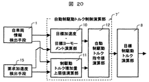
図20に示すように、自動制駆動トルク制御演算部7′は、目標加速度・目標ヨーモーメント演算部10,制駆動トルク増加量上限値演算部11,自動制駆動トルク指令値演算部12、からなる。
As shown in FIG. 20, the automatic braking / driving torque
ここで目標加速度・目標ヨーモーメント演算部10,制駆動トルク増加量上限値演算部11,自動制駆動トルク指令値演算部12での演算方法は、上述の第1の実施形態とほぼ同様であるが、上述の第1の実施形態での外界情報に基づいて演算されていた加速度が、要求加速度検出手段15により得られた要求加速度となることが異なる。
Here, the calculation methods in the target acceleration / target yaw
以上のように、要求加速度検出手段15により得られた要求加速度を自動制駆動トルク制御演算部7′にて演算し、制駆動トルク制御を行うことで、要求加速度検出手段15により発生する制駆動トルク上限値を操作性確保限界とした制駆動トルク制御が可能となる。これにより、ドライバが操作性確保限界を上限とした加速度制御を行いたい場合は、要求加速度検出手段15への操作入力を行い、摩擦限界を上限とした加速度制御を行いたい場合は、ブレーキペダルやアクセルペダルへの操作入力を行うといったドライバ自身による使い分けが可能となる。
As described above, the required acceleration obtained by the required
(発明を実施するための実施形態4)
以下、図21を用いて、本発明の第4の実施形態による車両運動制御装置の構成及び動作について説明する。
(Embodiment 4 for carrying out the invention)
Hereinafter, the configuration and operation of the vehicle motion control device according to the fourth embodiment of the present invention will be described with reference to FIG.
図21の構成では、車輪制駆動トルクアクチュエータ3として、ブレーキアクチュエータと制駆動モータアクチュエータの両方を、回生制動エネルギーを蓄える蓄電装置16を備えている。ブレーキアクチュエータは全ての車輪に備わり、制駆動モータアクチュエータは、後輪に連結されている。制駆動モータアクチュエータによって回生されたエネルギーは蓄電装置16へ供給される。
In the configuration of FIG. 21, as the wheel braking /
制動時に、車両の運動エネルギーをできる限り蓄電装置16へ回生するためには、ブレーキアクチュエータを作動させずに、制駆動モータアクチュエータのみで制動する方法がある。しかし、後輪で過度に制動力を発生させると、後輪の車輪が過度にスリップし、後輪の横力が不足し、車両運動の安定性が損なわれる恐れがある。そこで、実施形態1〜3に記載のように、制駆動トルク制御を行うことで、車輪ロックを発生させることなく、操作性確保限界内での制動トルクを発生させることができる。このとき、後輪の横力は十分確保されるため、車両運動の安定性を損なうことなく、車両の運動エネルギーを蓄電装置16へ回生できる。
In order to regenerate the kinetic energy of the vehicle to the
なお、ここでは、後輪の制駆動モータアクチュエータのみで制動する例を述べたが、ブレーキアクチュエータを併用することもできる。また、後輪に制駆動モータアクチュエータを備える例を述べたが、前輪に制駆動モータアクチュエータを備えてもよい。この場合、前輪による過度の回生制動を抑制し、車両の操縦性を確保できる。 Although an example in which braking is performed only with the braking / driving motor actuator for the rear wheel has been described here, a brake actuator can also be used in combination. Moreover, although the example which equips a rear wheel with a braking / driving motor actuator was described, you may equip a front wheel with a braking / driving motor actuator. In this case, excessive regenerative braking by the front wheels can be suppressed, and the controllability of the vehicle can be ensured.
1 自車両情報検出手段
2 車両運動制御演算手段
3 車輪制駆動トルクアクチュエータ
4 ブレーキランプ
5 外界情報取得手段
6 ドライバ要求制駆動トルク演算部
7 自動制駆動トルク制御演算部
8 目標制駆動トルク演算部
9 アクチュエータ駆動指令値演算部
10 目標加速度・目標ヨーモーメント演算部
11 制駆動トルク増加量上限値演算部
12 自動制駆動トルク指令値演算部
13 車両挙動安定化制駆動トルク補正制御演算部
14 摩擦限界制駆動トルク補正制御演算部
15 要求加速度検出手段
16 蓄電装置
DESCRIPTION OF SYMBOLS 1 Own vehicle information detection means 2 Vehicle motion control calculation means 3 Wheel braking / driving torque actuator 4
Claims (12)
前記操作入力情報には車両に横運動を発生させる横運動操作指標を含み、
前記車両運動情報には、車両に発生する前後加速度および車両横方向の運動を表す横運動指標を含み、
前記横運動操作指標が所定値以下、または前記横運動指標が所定値以下の領域において、前記横運動操作指標と前記横運動指標が比例する略線形関係となる前後加速度最大値を操作性確保限界加速度とし、前記操作性確保限界加速度を前記制駆動力制御により車両に発生させる前後加速度の上限値として、前記制駆動トルク制御を行う車両運動制御装置。 Based on at least one of the surrounding information or the vehicle information among vehicle information including vehicle surrounding information and driver operation input information and vehicle movement information, at least one of braking torque or driving torque of each wheel is controlled. A vehicle motion control device that performs braking / driving torque control,
The operation input information includes a lateral motion operation index for causing the vehicle to perform lateral motion,
The vehicle motion information includes a lateral motion index representing the longitudinal acceleration generated in the vehicle and the lateral motion of the vehicle,
In the region where the lateral movement operation index is equal to or less than a predetermined value or the lateral movement index is equal to or less than a predetermined value, the maximum longitudinal acceleration value having a substantially linear relationship in which the lateral movement operation index and the lateral movement index are proportional to each other is defined as a operability securing limit. A vehicle motion control device that performs the braking / driving torque control using acceleration as the upper limit value of the longitudinal acceleration to be generated in the vehicle by the braking / driving force control.
前記横運動操作指標は、操舵角の絶対値、もしくは横すべり角の絶対値の一部または全部であり、
前記横運動指標は、車両に発生する横加速度の絶対値、もしくは車両に発生するヨーレートの絶対値の少なくとも一部または全部である車両運動制御装置。 The vehicle motion control device according to claim 1,
The lateral movement operation index is an absolute value of a steering angle or a part or all of an absolute value of a side slip angle,
The vehicle motion control device, wherein the lateral motion index is at least part or all of an absolute value of a lateral acceleration generated in the vehicle or an absolute value of a yaw rate generated in the vehicle.
前記横運動操作指標が所定値および前記横運動指標の所定値は、予め設定される値,ドライバにより入力された値、もしくは前記周囲情報または操作入力情報の少なくとも一方に基づいて設定される値のうち、少なくとも一つの値である車両運動制御装置。 The vehicle motion control device according to claim 1,
The lateral movement operation index is a predetermined value and the predetermined value of the lateral movement index is a value set based on at least one of a preset value, a value input by a driver, or the surrounding information or the operation input information. A vehicle motion control device having at least one value.
前記前後加速度最大値は、各車輪に発生する制駆動力の制駆動トルク制御入力に対する非線形度合いに基づいて設定される値,推定または検知により自車両が走行している路面で発生可能とされた加速度限界、および前記操作性確保限界加速度に基づいて設定される値である車両運動制御装置。 The vehicle motion control device according to claim 1,
The maximum longitudinal acceleration value can be generated on the road surface on which the vehicle is traveling by a value set based on a non-linear degree of the braking / driving force generated at each wheel with respect to the braking / driving torque control input. A vehicle motion control device that is a value set based on an acceleration limit and the operability ensuring limit acceleration.
発生する前後力の上限値を前記摩擦限界、または発生する加速度の上限値を前記加速度限界としてドライバが制動トルクを入力する第1の制動トルク入力部と、
発生する制動力の上限値を前記操作性確保限界、または発生する加速度の上限値を前記操作性確保限界加速度としてドライバが制動トルクを入力する第2の制動トルク入力部と、を有する車両運動制御装置。 The vehicle motion control device according to claim 1,
A first braking torque input unit for a driver to input a braking torque with the upper limit value of the generated longitudinal force as the friction limit or the upper limit value of the generated acceleration as the acceleration limit;
Vehicle motion control having a second braking torque input unit for a driver to input a braking torque using the upper limit value of the generated braking force as the operability securing limit or the upper limit value of the generated acceleration as the operability securing limit acceleration. apparatus.
発生する前後力の上限値を前記摩擦限界、または発生する加速度の上限値を前記加速度限界としてドライバが駆動トルクを入力する第1の駆動トルク入力部と、
発生する制動力の上限値を前記操作性確保限界、または発生する加速度の上限値を前記操作性確保限界加速度としてドライバが駆動トルクを入力する第2の駆動トルク入力部とを有する車両運動制御装置。 The vehicle motion control device according to claim 1,
A first driving torque input unit for a driver to input driving torque with the upper limit value of the generated longitudinal force as the friction limit or the upper limit value of the generated acceleration as the acceleration limit;
A vehicle motion control device having a second driving torque input unit for a driver to input driving torque using the upper limit value of the generated braking force as the operability securing limit or the upper limit value of the generated acceleration as the operability securing limit acceleration. .
前記操作入力情報には車輪に横力を発生させる横力操作指標を含み、
前記車両運動情報には、車輪に発生する横力を表す車輪横力指標を含み、
前記横力操作指標が所定値以下、もしくは前記車輪横力指標が所定値以下の領域において、前記横力操作指標と前記車輪横力指標が比例する略線形関係となる前後力最大値を操作性確保限界とし、前記操作性確保限界を、前記制駆動トルク制御により車両に発生させる前後力の上限値として、前記制駆動トルクを行う車両運動制御装置。 Based on at least one of the surrounding information or the vehicle information among vehicle information including vehicle surrounding information and driver operation input information and vehicle movement information, at least one of braking torque or driving torque of each wheel is controlled. A vehicle motion control device that performs braking / driving torque control,
The operation input information includes a lateral force operation index for generating a lateral force on the wheel,
The vehicle motion information includes a wheel lateral force index representing a lateral force generated on the wheel,
In the region where the lateral force operation index is a predetermined value or less, or the wheel lateral force index is a predetermined value or less, the maximum longitudinal force value having a substantially linear relationship in which the lateral force operation index and the wheel lateral force index are proportional is determined. A vehicle motion control device that performs the braking / driving torque using the securing limit as an upper limit value of the longitudinal force generated in the vehicle by the braking / driving torque control.
前記横力操作指標は、操舵角の絶対値、もしくは車輪横すべり角の絶対値の一部または全部であり、
前記横力指標は、車輪に発生する横力,車両に発生する横加速度の絶対値、もしくは車両に発生するヨーレートの絶対値の一部または全部である車両運動制御装置。 The vehicle motion control device according to claim 7,
The lateral force operation index is a part or all of an absolute value of a steering angle or an absolute value of a wheel side slip angle,
The lateral force index is a vehicle motion control device that is a part or all of a lateral force generated on a wheel, an absolute value of a lateral acceleration generated on a vehicle, or an absolute value of a yaw rate generated on a vehicle.
前記横力操作指標が所定値および前記横力指標の所定値は、予め設定される値,ドライバにより入力された値、もしくは前記周囲情報または操作入力情報の少なくとも一方に基づいて設定される値のうち、少なくとも一つの値である車両運動制御装置。 The vehicle motion control device according to claim 7,
The lateral force operation index is a predetermined value and the predetermined value of the lateral force index is a preset value, a value input by a driver, or a value set based on at least one of the surrounding information or the operation input information. A vehicle motion control device having at least one value.
前記前後加速度最大値は、各車輪に発生する制駆動力の制駆動トルク制御入力に対する非線形度合いに基づいて設定される値,推定または検知により自車両が走行している路面で発生可能な前後力の摩擦限界、および前記操作性確保限界に基づいて設定される値である車両運動制御装置。 The vehicle motion control device according to claim 7,
The maximum longitudinal acceleration value is a value set based on the degree of nonlinearity of the braking / driving force generated at each wheel with respect to the braking / driving torque control input, and the longitudinal force that can be generated on the road surface on which the host vehicle is traveling by estimation or detection. The vehicle motion control device is a value set based on the friction limit and the operability securing limit.
発生する前後力の上限値を前記摩擦限界、または発生する加速度の上限値を前記加速度限界としてドライバが制動トルクを入力する第1の制動トルク入力部と、
発生する制動力の上限値を前記操作性確保限界、または発生する加速度の上限値を前記操作性確保限界加速度としてドライバが制動トルクを入力する第2の制動トルク入力部と、を有する車両運動制御装置。 The vehicle motion control device according to claim 7,
A first braking torque input unit for a driver to input a braking torque with the upper limit value of the generated longitudinal force as the friction limit or the upper limit value of the generated acceleration as the acceleration limit;
Vehicle motion control having a second braking torque input unit for a driver to input a braking torque using the upper limit value of the generated braking force as the operability securing limit or the upper limit value of the generated acceleration as the operability securing limit acceleration. apparatus.
発生する前後力の上限値を前記摩擦限界、または発生する加速度の上限値を前記加速度限界としてドライバが駆動トルクを入力する第1の駆動トルク入力部と、
発生する制動力の上限値を前記操作性確保限界、または発生する加速度の上限値を前記操作性確保限界加速度としてドライバが駆動トルクを入力する第2の駆動トルク入力部とを有する車両運動制御装置。 The vehicle motion control device according to claim 7,
A first driving torque input unit for a driver to input driving torque with the upper limit value of the generated longitudinal force as the friction limit or the upper limit value of the generated acceleration as the acceleration limit;
A vehicle motion control device having a second driving torque input unit for a driver to input driving torque using the upper limit value of the generated braking force as the operability securing limit or the upper limit value of the generated acceleration as the operability securing limit acceleration. .
Priority Applications (4)
| Application Number | Priority Date | Filing Date | Title |
|---|---|---|---|
| JP2009080852A JP4920054B2 (en) | 2009-03-30 | 2009-03-30 | Vehicle motion control device |
| US12/709,040 US20100250083A1 (en) | 2009-03-30 | 2010-02-19 | Vehicle Dynamics Control Device |
| EP10154107.6A EP2236376B1 (en) | 2009-03-30 | 2010-02-19 | Vehicle dynamics control device |
| US14/217,590 US8983748B2 (en) | 2009-03-30 | 2014-03-18 | Vehicle dynamics control device |
Applications Claiming Priority (1)
| Application Number | Priority Date | Filing Date | Title |
|---|---|---|---|
| JP2009080852A JP4920054B2 (en) | 2009-03-30 | 2009-03-30 | Vehicle motion control device |
Publications (2)
| Publication Number | Publication Date |
|---|---|
| JP2010228690A true JP2010228690A (en) | 2010-10-14 |
| JP4920054B2 JP4920054B2 (en) | 2012-04-18 |
Family
ID=42103000
Family Applications (1)
| Application Number | Title | Priority Date | Filing Date |
|---|---|---|---|
| JP2009080852A Active JP4920054B2 (en) | 2009-03-30 | 2009-03-30 | Vehicle motion control device |
Country Status (3)
| Country | Link |
|---|---|
| US (2) | US20100250083A1 (en) |
| EP (1) | EP2236376B1 (en) |
| JP (1) | JP4920054B2 (en) |
Cited By (5)
| Publication number | Priority date | Publication date | Assignee | Title |
|---|---|---|---|---|
| EP2626259A1 (en) | 2012-02-09 | 2013-08-14 | Hitachi Automotive Systems, Ltd. | Vehicle motion control apparatus, and vehicle motion control method |
| KR20140075745A (en) * | 2011-09-20 | 2014-06-19 | 지멘스 악티엔게젤샤프트 | Vehicle with an anti-lock braking system and method for braking a vehicle |
| JPWO2013046299A1 (en) * | 2011-09-26 | 2015-03-26 | トヨタ自動車株式会社 | Vehicle driving support system |
| CN104812612A (en) * | 2012-11-21 | 2015-07-29 | 日立汽车系统株式会社 | Vehicle control device |
| WO2016051942A1 (en) * | 2014-09-29 | 2016-04-07 | 日立オートモティブシステムズ株式会社 | Method and device for controlling vehicle motion and vehicle equipped with same |
Families Citing this family (38)
| Publication number | Priority date | Publication date | Assignee | Title |
|---|---|---|---|---|
| US20070213911A1 (en) * | 2006-03-09 | 2007-09-13 | Ford Global Technologies, Llc | Trailbraking |
| US8062175B2 (en) * | 2008-11-04 | 2011-11-22 | GM Global Technology Operations LLC | Method and apparatus for optimizing braking control during a threshold braking event |
| JP5143103B2 (en) * | 2009-09-30 | 2013-02-13 | 日立オートモティブシステムズ株式会社 | Vehicle motion control device |
| JP5542014B2 (en) * | 2010-09-10 | 2014-07-09 | 富士重工業株式会社 | Vehicle behavior control device |
| GB2483720B (en) * | 2010-09-20 | 2017-10-25 | Jaguar Land Rover Ltd | Improvements relating to brake control |
| DE102012216218A1 (en) * | 2011-09-12 | 2013-03-14 | Continental Teves Ag & Co. Ohg | Sensor system comprising a fusion filter for common signal processing |
| JP5838681B2 (en) * | 2011-09-16 | 2016-01-06 | いすゞ自動車株式会社 | Actuator control method and actuator control apparatus |
| US8855844B2 (en) * | 2011-10-11 | 2014-10-07 | Robert Bosch Gmbh | System and method for optimal deceleration of a vehicle using regenerative braking |
| US8587424B2 (en) * | 2011-12-05 | 2013-11-19 | David Aberizk | Vehicle regenerative deceleration actuator and indicator system and method |
| US8965609B2 (en) * | 2011-12-29 | 2015-02-24 | Kawasaki Jukogyo Kabushiki Kaisha | Electric vehicle |
| JP2014076715A (en) * | 2012-10-10 | 2014-05-01 | Mitsubishi Motors Corp | Brake lamp control device |
| BR112015024404A2 (en) * | 2013-03-28 | 2017-07-18 | Honda Motor Co Ltd | vehicle brake system |
| JP2014193691A (en) | 2013-03-29 | 2014-10-09 | Hitachi Automotive Systems Ltd | Vehicle motion controller |
| JP5880500B2 (en) * | 2013-08-29 | 2016-03-09 | トヨタ自動車株式会社 | vehicle |
| JP6138655B2 (en) | 2013-10-10 | 2017-05-31 | 日立オートモティブシステムズ株式会社 | Vehicle motion control device |
| KR101890440B1 (en) * | 2013-11-11 | 2018-09-28 | 주식회사 만도 | Braking pressure maximum limitation method of brake traction control system |
| DE102014208524A1 (en) * | 2014-05-07 | 2015-11-12 | Robert Bosch Gmbh | LOCAL TRANSPORTATION ANALYSIS WITH DETECTION OF A TRAFFIC PATH |
| US9707967B2 (en) * | 2015-06-30 | 2017-07-18 | Kelsey-Hayes Company | Method of traction control for a motor vehicle |
| CN105083280A (en) * | 2015-07-27 | 2015-11-25 | 北汽福田汽车股份有限公司 | Method and system for controlling torque of four-wheel-drive vehicle |
| WO2017081713A1 (en) * | 2015-11-09 | 2017-05-18 | 日産自動車株式会社 | Braking/driving force control method and braking/driving force control device |
| JP6604894B2 (en) * | 2016-04-12 | 2019-11-13 | 日立オートモティブシステムズ株式会社 | Vehicle control apparatus and method |
| US10053070B2 (en) * | 2016-05-19 | 2018-08-21 | General Electric Company | System and method for traction control |
| WO2017215751A1 (en) * | 2016-06-15 | 2017-12-21 | Volvo Truck Corporation | A wheel controller for a vehicle |
| JP6764478B2 (en) * | 2016-06-15 | 2020-09-30 | 日立オートモティブシステムズ株式会社 | Vehicle control device |
| DE102016211728A1 (en) * | 2016-06-29 | 2018-01-04 | Trw Automotive U.S. Llc | Reibwertschätzer |
| JP6765908B2 (en) * | 2016-09-07 | 2020-10-07 | Ntn株式会社 | Vehicle turn control device |
| JP6786511B2 (en) * | 2016-11-17 | 2020-11-18 | バイドゥドットコム タイムズ テクノロジー (ベイジン) カンパニー リミテッドBaidu.com Times Technology (Beijing) Co., Ltd. | Methods and systems for tracking the speed of autonomous vehicles |
| CN106740769B (en) * | 2016-12-26 | 2019-03-26 | 清华大学苏州汽车研究院(相城) | A kind of autonomous emergency braking control algolithm that road surface attachment is adaptive |
| JP6990622B2 (en) * | 2018-04-26 | 2022-01-12 | 日立Astemo株式会社 | Controlling force control device, vehicle control method and vehicle control system |
| US11345327B2 (en) | 2018-08-06 | 2022-05-31 | Xl Hybrids, Inc. | Throttle signal controller for a dynamic hybrid vehicle |
| JP7124561B2 (en) * | 2018-08-28 | 2022-08-24 | 株式会社デンソー | swivel control device |
| CN111452781B (en) * | 2020-03-24 | 2023-01-17 | 东南大学 | Strong-robustness self-adaptive driving anti-skid control method for improving acceleration comfort of hub motor driven electric automobile |
| CN111746501B (en) * | 2020-07-06 | 2021-08-20 | 清华大学 | Vehicle operation limit expansion method and system based on driving and braking cooperative control |
| CN115743081A (en) * | 2021-03-23 | 2023-03-07 | 武汉路特斯汽车有限公司 | Chassis control method and chassis control system |
| CN113200034A (en) * | 2021-05-31 | 2021-08-03 | 联合汽车电子有限公司 | Torque control method and device, storage medium and vehicle |
| CN113928339A (en) * | 2021-10-21 | 2022-01-14 | 东风悦享科技有限公司 | Vehicle longitudinal motion control system and method based on state judgment and error feedback |
| CN114633780B (en) * | 2021-12-30 | 2022-11-25 | 中南大学 | Heavy-duty train and longitudinal dynamics traction operation optimization control system thereof |
| CN115946546B (en) * | 2023-01-17 | 2024-04-16 | 重庆赛力斯新能源汽车设计院有限公司 | Single pedal mode deceleration operation control method and system for electric automobile under rough road condition |
Citations (5)
| Publication number | Priority date | Publication date | Assignee | Title |
|---|---|---|---|---|
| JP2003261016A (en) * | 2002-03-08 | 2003-09-16 | Toyota Central Res & Dev Lab Inc | Device for estimating maximum road surface friction coefficient |
| JP2007106273A (en) * | 2005-10-14 | 2007-04-26 | Nissan Motor Co Ltd | Vehicle running state estimating device |
| JP2007112367A (en) * | 2005-10-24 | 2007-05-10 | Hitachi Ltd | Vehicle tire state detection method and device |
| JP2007269294A (en) * | 2006-03-31 | 2007-10-18 | Toyota Central Res & Dev Lab Inc | Apparatus and method for controlling vehicle motion |
| WO2008133150A1 (en) * | 2007-04-17 | 2008-11-06 | Nissan Motor Co., Ltd. | Device and method for estimating frictional condition of ground contact surface of wheel |
Family Cites Families (13)
| Publication number | Priority date | Publication date | Assignee | Title |
|---|---|---|---|---|
| JPH03189338A (en) * | 1989-12-19 | 1991-08-19 | Japan Electron Control Syst Co Ltd | Traction control unit |
| JPH061229A (en) | 1992-06-19 | 1994-01-11 | Fuji Heavy Ind Ltd | Method for controlling automatic braking device |
| JP3062777B2 (en) | 1992-07-14 | 2000-07-12 | 本田技研工業株式会社 | Vehicle speed control device |
| JP3784436B2 (en) * | 1995-11-20 | 2006-06-14 | 本田技研工業株式会社 | Vehicle braking force control device |
| JPH10269499A (en) | 1997-03-26 | 1998-10-09 | Mitsubishi Motors Corp | Vehicle speed controller |
| DE10130663A1 (en) * | 2001-06-28 | 2003-01-23 | Continental Teves Ag & Co Ohg | Method for modifying a driving stability control of a vehicle |
| JP4089359B2 (en) * | 2002-09-03 | 2008-05-28 | 株式会社日立製作所 | Control device for hybrid vehicle |
| WO2008088304A2 (en) * | 2005-12-15 | 2008-07-24 | The Goodyear Tire & Rubber Company | A method of determining vehicle properties |
| JP2007216839A (en) | 2006-02-16 | 2007-08-30 | Fujitsu Ten Ltd | Operation assistance device and operation assistance method |
| JP4636012B2 (en) * | 2006-12-11 | 2011-02-23 | トヨタ自動車株式会社 | Brake control device for vehicle |
| JP4568302B2 (en) | 2007-05-18 | 2010-10-27 | 株式会社日立製作所 | Vehicle longitudinal acceleration control apparatus using jerk information |
| JP2009120116A (en) | 2007-11-16 | 2009-06-04 | Hitachi Ltd | Vehicle collision avoidance support device |
| CN102143869B (en) * | 2008-11-25 | 2014-07-16 | 丰田自动车株式会社 | Travel control device for vehicle |
-
2009
- 2009-03-30 JP JP2009080852A patent/JP4920054B2/en active Active
-
2010
- 2010-02-19 US US12/709,040 patent/US20100250083A1/en not_active Abandoned
- 2010-02-19 EP EP10154107.6A patent/EP2236376B1/en active Active
-
2014
- 2014-03-18 US US14/217,590 patent/US8983748B2/en active Active
Patent Citations (5)
| Publication number | Priority date | Publication date | Assignee | Title |
|---|---|---|---|---|
| JP2003261016A (en) * | 2002-03-08 | 2003-09-16 | Toyota Central Res & Dev Lab Inc | Device for estimating maximum road surface friction coefficient |
| JP2007106273A (en) * | 2005-10-14 | 2007-04-26 | Nissan Motor Co Ltd | Vehicle running state estimating device |
| JP2007112367A (en) * | 2005-10-24 | 2007-05-10 | Hitachi Ltd | Vehicle tire state detection method and device |
| JP2007269294A (en) * | 2006-03-31 | 2007-10-18 | Toyota Central Res & Dev Lab Inc | Apparatus and method for controlling vehicle motion |
| WO2008133150A1 (en) * | 2007-04-17 | 2008-11-06 | Nissan Motor Co., Ltd. | Device and method for estimating frictional condition of ground contact surface of wheel |
Cited By (9)
| Publication number | Priority date | Publication date | Assignee | Title |
|---|---|---|---|---|
| KR20140075745A (en) * | 2011-09-20 | 2014-06-19 | 지멘스 악티엔게젤샤프트 | Vehicle with an anti-lock braking system and method for braking a vehicle |
| KR101975623B1 (en) * | 2011-09-20 | 2019-05-07 | 루카스 오토모티브 게엠베하 | Vehicle with an anti-lock braking system and method for braking a vehicle |
| JPWO2013046299A1 (en) * | 2011-09-26 | 2015-03-26 | トヨタ自動車株式会社 | Vehicle driving support system |
| EP2626259A1 (en) | 2012-02-09 | 2013-08-14 | Hitachi Automotive Systems, Ltd. | Vehicle motion control apparatus, and vehicle motion control method |
| JP2013163422A (en) * | 2012-02-09 | 2013-08-22 | Hitachi Automotive Systems Ltd | Vehicle motion control apparatus and vehicle motion control method |
| CN104812612A (en) * | 2012-11-21 | 2015-07-29 | 日立汽车系统株式会社 | Vehicle control device |
| WO2016051942A1 (en) * | 2014-09-29 | 2016-04-07 | 日立オートモティブシステムズ株式会社 | Method and device for controlling vehicle motion and vehicle equipped with same |
| JP2016068649A (en) * | 2014-09-29 | 2016-05-09 | 日立オートモティブシステムズ株式会社 | Motion control method of vehicle, device, and vehicle mounted with the same |
| US10384673B2 (en) | 2014-09-29 | 2019-08-20 | Hitachi Automotive Systems, Ltd. | Method and device for controlling vehicle motion and vehicle equipped with same |
Also Published As
| Publication number | Publication date |
|---|---|
| EP2236376A1 (en) | 2010-10-06 |
| EP2236376B1 (en) | 2015-04-15 |
| US8983748B2 (en) | 2015-03-17 |
| JP4920054B2 (en) | 2012-04-18 |
| US20140200787A1 (en) | 2014-07-17 |
| US20100250083A1 (en) | 2010-09-30 |
Similar Documents
| Publication | Publication Date | Title |
|---|---|---|
| JP4920054B2 (en) | Vehicle motion control device | |
| JP6073941B2 (en) | Vehicle travel control device | |
| JP5879143B2 (en) | Vehicle motion control device and vehicle motion control method | |
| EP3530535B1 (en) | Vehicle movement control device, vehicle movement control method, and vehicle movement control program | |
| US9020699B2 (en) | Method and braking system for influencing driving dynamics by means of braking and driving operations | |
| JP3617502B2 (en) | Lane departure prevention device | |
| JP6229879B2 (en) | Vehicle behavior control device | |
| US8395491B2 (en) | Method for controlling driving stability | |
| US20140129090A1 (en) | Drive controlling apparatus for a vehicle | |
| CN105683018A (en) | Improvements in vehicle speed control | |
| CN105283364B (en) | Vehicle speed control system | |
| US11072337B2 (en) | Method for ascertaining the coefficient of friction between a vehicle wheel and the roadway | |
| JP5841265B2 (en) | Wheel control device, vehicle, wheel control method | |
| JP5503260B2 (en) | Vehicle motion control device | |
| US8874346B2 (en) | System with blended anti-lock and stability control | |
| JP2014212614A (en) | Wheel controller, vehicle, wheel control method | |
| KR102416064B1 (en) | Lateral dynamic control for regenerative and friction braking mixture | |
| WO2016092586A1 (en) | Braking/driving force control device and braking/driving force control method | |
| JP2006200526A (en) | Output characteristic control device for vehicle | |
| JP2006525176A (en) | Method and apparatus for adjusting the running force of a vehicle | |
| JP2003104186A (en) | Acceleration slip control device for four-wheel drive vehicle | |
| JP4928221B2 (en) | Vehicle behavior control device | |
| WO2023029711A1 (en) | Chassis domain control method under high-speed working condition, and related apparatus | |
| JP2009184625A (en) | Road surface friction coefficient estimation device and driving force distribution controller for four-wheel drive vehicle having the road surface friction coefficient estimation device | |
| JP2015030314A (en) | Vehicle control device |
Legal Events
| Date | Code | Title | Description |
|---|---|---|---|
| A621 | Written request for application examination |
Free format text: JAPANESE INTERMEDIATE CODE: A621 Effective date: 20110121 |
|
| A131 | Notification of reasons for refusal |
Free format text: JAPANESE INTERMEDIATE CODE: A131 Effective date: 20110301 |
|
| A521 | Request for written amendment filed |
Free format text: JAPANESE INTERMEDIATE CODE: A523 Effective date: 20110830 |
|
| A131 | Notification of reasons for refusal |
Free format text: JAPANESE INTERMEDIATE CODE: A131 Effective date: 20111004 |
|
| A521 | Request for written amendment filed |
Free format text: JAPANESE INTERMEDIATE CODE: A523 Effective date: 20111202 |
|
| TRDD | Decision of grant or rejection written | ||
| A01 | Written decision to grant a patent or to grant a registration (utility model) |
Free format text: JAPANESE INTERMEDIATE CODE: A01 Effective date: 20120104 |
|
| A01 | Written decision to grant a patent or to grant a registration (utility model) |
Free format text: JAPANESE INTERMEDIATE CODE: A01 |
|
| A61 | First payment of annual fees (during grant procedure) |
Free format text: JAPANESE INTERMEDIATE CODE: A61 Effective date: 20120131 |
|
| R151 | Written notification of patent or utility model registration |
Ref document number: 4920054 Country of ref document: JP Free format text: JAPANESE INTERMEDIATE CODE: R151 |
|
| FPAY | Renewal fee payment (event date is renewal date of database) |
Free format text: PAYMENT UNTIL: 20150210 Year of fee payment: 3 |
|
| S111 | Request for change of ownership or part of ownership |
Free format text: JAPANESE INTERMEDIATE CODE: R313113 |
|
| R350 | Written notification of registration of transfer |
Free format text: JAPANESE INTERMEDIATE CODE: R350 |
|
| S533 | Written request for registration of change of name |
Free format text: JAPANESE INTERMEDIATE CODE: R313533 |
|
| R350 | Written notification of registration of transfer |
Free format text: JAPANESE INTERMEDIATE CODE: R350 |
|
| R250 | Receipt of annual fees |
Free format text: JAPANESE INTERMEDIATE CODE: R250 |