JP2010226902A - Motor stator and divided stator - Google Patents
Motor stator and divided stator Download PDFInfo
- Publication number
- JP2010226902A JP2010226902A JP2009073112A JP2009073112A JP2010226902A JP 2010226902 A JP2010226902 A JP 2010226902A JP 2009073112 A JP2009073112 A JP 2009073112A JP 2009073112 A JP2009073112 A JP 2009073112A JP 2010226902 A JP2010226902 A JP 2010226902A
- Authority
- JP
- Japan
- Prior art keywords
- peripheral
- stator
- divided
- coil
- radius
- Prior art date
- Legal status (The legal status is an assumption and is not a legal conclusion. Google has not performed a legal analysis and makes no representation as to the accuracy of the status listed.)
- Pending
Links
Images


Abstract
Description
本発明は、複数の分割ステータを円周状に配置して形成したモータステータおよび分割ステータに関する。 The present invention relates to a motor stator and a divided stator formed by arranging a plurality of divided stators circumferentially.
従来より、各種のモータが広く普及しているが、特に大出力のモータでは、高負荷、低回転域において、電流量増加に伴うコイルでの銅損発熱によるコイルの温度上昇が問題になる。例えば、コイルの絶縁被覆材として使用されているエナメルの耐熱温度などからモータには作動温度上限が存在し、作動温度をそれ以下にしなければならない。そこで、モータの駆動制御範囲を作動温度が上限温度以下になるように限定したり、モータを大型化して作動温度の上昇を抑制したりしている。しかし、このような手法では、小型で大出力のモータを得ることが難しい。 Conventionally, various types of motors have been widely used. However, particularly in a high-power motor, an increase in coil temperature due to heat generated by copper loss accompanying an increase in current amount becomes a problem in a high load and low rotation range. For example, the upper limit of the operating temperature exists in the motor due to the heat resistant temperature of the enamel used as the insulating coating material of the coil, and the operating temperature must be lower than that. Therefore, the drive control range of the motor is limited so that the operating temperature is equal to or lower than the upper limit temperature, or the motor is enlarged to suppress the increase in operating temperature. However, with such a technique, it is difficult to obtain a small and high output motor.
このため、冷却機構を設けて、温度上昇を抑制する手段も採られている。特許文献1には、分割ステータの軸方向両端部を保持するステータ支持部材を有し、このステータ支持部材を良熱伝導材で構成して放熱を促進すること、およびステータ支持部材内に冷却流路を設けることが示されている。
For this reason, a means for suppressing the temperature rise by providing a cooling mechanism is also employed.
特許文献2には、ステータ内部に油の流通する流路を設け、ステータを冷却する構成が示されている。
特許文献3には、ステータのコイルを配置するスロットに冷却通路を形成する構成が示されている。
しかし、特許文献1では、コアの中心部分についての冷却およびその部分のコイルの冷却が難しい。特許文献2においても、ステータ全体を効果的に冷却するのが難しく、コイル全体を効果的に冷却することが難しい。また、特許文献3では、冷媒である油を均一に循環することが難しく、全体として効果的に冷却することが難しいという問題があった。
However, in
本発明は、複数の分割ステータを円周状に配置して形成したモータステータであって、各分割ステータは、外周側の周辺分割コア部と、周辺分割コア部から中心方向に伸びるティース部と、ティース部に巻回されたコイルを含み、前記コイルの内周側の幅である内周長Lin、周辺分割コア部の外周長さである外周長Lout、前記コイルの内周側の半径である内周半径Rin、周辺分割コア部の半径である外周半径Routとした場合に、Lin/Rin<Lout/Routを満たし、複数の分割ステータを円周状に配置した場合に、各分割ステータ間に内側から外側に向けて広がるくさび状の空間を設け、この空間に金属材料から構成される熱伝導フィンが配置されていることを特徴とする。 The present invention is a motor stator formed by arranging a plurality of divided stators in a circumferential shape, and each divided stator includes a peripheral divided core portion on the outer peripheral side, and a teeth portion extending in the center direction from the peripheral divided core portion. , Including a coil wound around the tooth portion, and an inner peripheral length Lin that is a width on the inner peripheral side of the coil, an outer peripheral length Lout that is an outer peripheral length of the peripheral divided core portion, and a radius on the inner peripheral side of the coil When a certain inner peripheral radius Rin and an outer peripheral radius Rout that is a radius of the peripheral divided core portion are satisfied, Lin / Rin <Lout / Rout is satisfied, and when a plurality of divided stators are arranged in a circumferential shape, A wedge-shaped space extending from the inside toward the outside is provided in the space, and heat conduction fins made of a metal material are disposed in this space.
また、前記熱伝導フィンは、前記分割ステータの周辺分割コア部の一部を延長して形成することが好適である。 Further, it is preferable that the heat conducting fin is formed by extending a part of a peripheral divided core portion of the divided stator.
また、前記コイルは、板状の平型導線をその内側がティース部に接するように巻回し、この平型導線の外側の側部が前記熱伝導フィンに接触することが好適である。 Further, it is preferable that the coil is wound with a plate-shaped flat conductive wire so that the inner side thereof is in contact with the teeth portion, and the outer side portion of the flat conductive wire is in contact with the heat conductive fin.
また、複数の分割ステータを熱伝導フィンを含めて円周状に配置し、これを外周側より締結リングで焼きばめすることが好適である。 In addition, it is preferable to arrange a plurality of divided stators including the heat conductive fins in a circumferential shape and to shrink them with a fastening ring from the outer peripheral side.
また、前記締結リングの外側にケースを配置するとともに、このケースと焼きばめリングの間に冷却媒体を流通する冷却路を設けたことが好適である。 In addition, it is preferable that a case is disposed outside the fastening ring, and a cooling path for circulating a cooling medium is provided between the case and the shrink fitting ring.
また、複数個を円周状に配置してモータステータを形成するための分割ステータであって、周辺分割コア部と、周辺分割コア部から中心方向に伸びるティース部と、ティース部に巻回されたコイルを含み、前記コイルの内周側の幅である内周長Lin、周辺分割コア部の外周長さである外周長Lout、前記コイルの内周側の半径である内周半径Rin、周辺分割コア部の半径である外周半径Routとした場合に、Lin/Rin<Lout/Routを満たすことが好適である。 Further, a split stator for forming a motor stator by arranging a plurality of circumferences, a peripheral split core part, a tooth part extending in the center direction from the peripheral split core part, and wound around the tooth part An inner peripheral length Lin that is an inner peripheral side width of the coil, an outer peripheral length Lout that is an outer peripheral length of a peripheral divided core portion, an inner peripheral radius Rin that is an inner peripheral side radius of the coil, It is preferable that Lin / Rin <Lout / Rout is satisfied when the outer peripheral radius Rout, which is the radius of the divided core portion, is used.
また、円周方向の一端側または両端側に中心方向に伸びるくさび形の伝熱フィン部を設け、内周長Linおよび外周長Loutにこの伝熱フィン部の長さを加えた場合にLin/Rin=Lout/Routとなることが好適である。 Further, a wedge-shaped heat transfer fin portion extending in the center direction is provided on one end side or both end sides in the circumferential direction, and when the length of the heat transfer fin portion is added to the inner peripheral length Lin and the outer peripheral length Lout, Lin / It is preferable that Rin = Lout / Rout.
本発明によれば、熱良導体から形成された伝熱フィンをコイルに接触させることで、この伝熱フィンを介し、コイルの効果的な放熱が行える。 According to the present invention, the heat transfer fin formed from the heat good conductor is brought into contact with the coil, whereby the coil can effectively dissipate heat through the heat transfer fin.
以下、本発明の実施形態について、図面に基づいて説明する。 Hereinafter, embodiments of the present invention will be described with reference to the drawings.
図1は、分割ステータの分割コア部3と伝熱フィン部5の部分を軸方向から見た平面図である。分割コア部3は、外側に円周上に配置される周辺分割コア部3aと、この周辺分割コア部3aの中央部分から内側方向に伸びるティース部3bとからなっている。周辺分割コア部3aの両端部分には、内側に伸びるくさび型の伝熱フィン部5が形成されている。
FIG. 1 is a plan view of the split
本実施形態においては、周辺分割コア部3aは半径方向の厚み一定の部分であって、側部に位置するくさび型の伝熱フィン部5を含まないものとしている。すなわち、周辺分割コア部3aは、伝熱フィン部5を介して、隣の周辺分割コア部3aに接続され、所定数の分割コア部3を円周状に並べることでドーナツ状のステータコアが形成される。この例では、周辺分割コア部3aの両側に伝熱フィン部5が設けられているので、隣接する2つの分割ステータの伝熱フィン部5が合体して1つの伝熱フィン部5として機能することになる。なお、分割コア部3は、全体として、電磁鋼板を積層して形成されている。
In the present embodiment, the peripherally divided
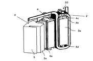
そして、図2に示すように、分割コア部3のティース部3bの周囲には、図3に示すインシュレータ4を介し、コイル2が巻回されて、分割ステータ20が構成される。なお、図2においては、インシュレータ4を省略して記載してある。コイル2は、薄板状の銅製平型導線からなり、これを複数回ティース部3bに巻回して形成された半径方向に伸びるコイルである。この例において、コイル2の半径方向の中心側の端面(内周側端面)は、ティース部3bの中心側の端面(内周側端面)とほぼ同一面を形成している。ティース部3bは、平面形状が内側に向けて断面積が減少する台形状である、ステータの周辺部から中心へ向く角柱状となっており、このティース部3bの周囲にインシュレータ4を介しコイル2が巻回される。
As shown in FIG. 2, the
コイル2は平型導線の一重巻であり、その幅自体は一定であるため、コイル2の外側端はティース部3bの外周と同様に中心側に向けて徐々に先すぼまりとなる。本例では、コイル2のステータ中心側端面と、ティース部3bの端面はほぼ同一面となっているが、必ずしも同一面を形成する必要はない。しかし、コイル2をなるべく多く効率的に収容するためには、コイル2の中心側の面とティース部3b中心側の面はほぼ同一面であることが好ましい。
Since the
また、伝熱フィン部5は、コイル2の内周側面まで伸びて、内周側においてある程度の大きさを持っていてもよいが、コイル2をなるべく多く収容し、また不要な磁束漏れの発生を防止するためには、半径方向内側のある程度の部分においてコイル2の円周方向外側が直接隣接のコイル2と接触する方がよい。
The heat
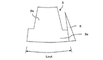
本実施形態の分割ステータ20において、コイル2の内周側(中心側)の幅である内周長をLin、伝熱フィン部5を除いた周辺分割コア部3aの外周側の幅である外周長をLout、前記コイル2の内周側の半径である内周半径をRin、周辺分割コア部3aの半径である外周半径をRoutとした場合、Lin/Rin<Lout/Routを満たす。一方、伝熱フィン部5を含めた周辺分割コア部3aの外周長さを外周長Loutとした場合には、Lin/Rin=Lout/Routとなる。従って、伝熱フィン部5を含めた分割ステータを円周状に配置することで、ドーナツ状のモータステータが得られる。
In the
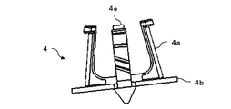
ここで、上述したように、ティース部3bの周囲とコイル2の内周側との間には、合成樹脂製のインシュレータ4が配置されている。図3には、インシュレータ4の平面図が示されており、図4にも、内側から見たインシュレータ4の一部が示されている。インシュレータ4は、ティース部3bの側面を覆う部分4aと、ティース部3bの上部、下部の一部に配置した部分4c,4dと、周辺分割コア部3aの内周面に沿った部分4bとを有し、これによってコイル2をティース部3bおよび周辺分割コア部3aから隔離している。さらに、インシュレータ4の一部は、コイル2の上部に配置され、ここがコイル2の周辺回路との接続用配線を支持する部分4eを構成している。また、インシュレータ4のティース側の部分4aの先端部は、周方向に少し広がるつばを有しており、コイル2の内周側端面を保持するようになっている。
Here, as described above, the
図4は、3つの分割ステータ20を円周状に配置した状態を示しており、1つの分割ステータ20は分割コア部3とコイル2とインシュレータ4を記載し、1つの分割ステータ20は分割コア部3とインシュレータ4を記載し、もう1つの分割ステータは、分割コア部3のみを記載している。
FIG. 4 shows a state in which three divided
図5には、分割ステータ20の他の構成例について示してある。この例では、伝熱フィン部5を周辺分割コア部3aの一端側のみに配置している。このような分割ステータ20を用いても、上述の場合と同様にして、これを円周状に配置して、モータステータを形成することができる。なお、図5の構成の方が、図1の構成より、製造しやすいというメリットがある。しかし、分割コア3内の磁路が、ティース部3bに対して熱的に対称境界となるという点で界面での条件を緩和でき、図1の構成の方が好適である。
FIG. 5 shows another configuration example of the divided
図6の例では、伝熱フィン部5を分割ステータと別部材で形成している。この場合、伝熱フィン部5をアルミや、銅などの被磁性体で形成することが好適であり、これによって伝熱フィン部5に磁束が漏れることを防止できる。なお、伝熱フィン部5は、図1のように分割コア部3の両側に配置してもよい。
In the example of FIG. 6, the heat
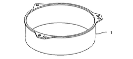
モータステータを形成する場合には、まず分割ステータ20の分割コア部3にインシュレータ4を配置する。次に、インシュレータ4にコイル2をはめ込む。そして、このようにしてできた分割ステータ20を円周上に並べ、これを締結リング内に焼きばめする。すなわち、熱した状態の締結リング1内に分割ステータを円周状に並べたものを収容し、温度を低下させて締め付ける。図7に締結リング1の構成例を示し、図8に複数の分割ステータを焼きばめした状態を示す。
When forming a motor stator, first, the
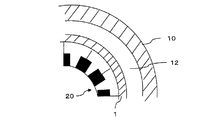
図9、図10には、冷媒流路12を締結リング1の外側に直接形成する構成を示す。すなわち、締結リング1に収容されたモータステータは、ケース10内に収められる。そして、このケース10と、締結リング1の間に、冷媒流路12が形成されている。この冷媒流路12は、ケース10または締結リング1の表面に設けた凸条や、仕切り凸条によって、螺旋流路としたり、複数の並列流路とすることができる。また、この例では、冷媒流路12の上下は、オーリング14によりシールしている。このような、オーリング14によるシールによって、簡単に冷媒流路12のシールを行うことができる。なお、ケース10に、冷媒の流入管および流出管を設け、冷媒流路12に冷媒を流通すればよい。また、冷媒としては各種の液体が利用可能であるが、水やATFなどの油が好適である。
9 and 10 show a configuration in which the
このように、本実施形態に係るモータステータでは、1つの分割ステータ20におけるコイル2の外周が直接伝熱フィン5に接触する。このため、コイル2において発生した熱が伝熱フィンに容易に伝わる。そして、この伝熱フィン5は、分割コア部3の間にも存在し、締結リング1にまで至るくさび型をしている。従って、コイル2で発生した熱が、伝熱フィン5を介し、締結リング1にまで容易に伝達される。そして、締結リング1の外側には冷媒が流通しているため、冷媒にまで熱が効果的に放散できる。従って、コイル2の発熱量が多くても、温度上昇を抑えることができ、高出力のモータを得ることが可能になる。また、伝熱フィン5は、くさび型をしており、コイル2の熱をより多く伝達する部分の体積がより大きくなっており、熱の効果的な伝達が達成される。
Thus, in the motor stator according to the present embodiment, the outer periphery of the
1 締結リング、2 コイル、3 分割コア部、3a 周辺分割コア部、3b ティース部、4 インシュレータ、5 伝熱フィン部、10 ケース、12 冷媒流路、14 オーリング、20 分割ステータ。
DESCRIPTION OF
Claims (7)
各分割ステータは、
外周側の周辺分割コア部と、周辺分割コア部から中心方向に伸びるティース部と、ティース部に巻回されたコイルを含み、
前記コイルの内周側の幅である内周長Lin、周辺分割コア部の外周長さである外周長Lout、前記コイルの内周側の半径である内周半径Rin、周辺分割コア部の半径である外周半径Routとした場合に、Lin/Rin<Lout/Routを満たし、複数の分割ステータを円周状に配置した場合に、各分割ステータ間に内側から外側に向けて広がるくさび状の空間を設け、
この空間に金属材料から構成される熱伝導フィンが配置されていることを特徴とするモータステータ。 A motor stator formed by arranging a plurality of divided stators circumferentially,
Each split stator
Including a peripheral divided core portion on the outer peripheral side, a teeth portion extending in the center direction from the peripheral divided core portion, and a coil wound around the teeth portion;
The inner peripheral length Lin that is the width of the inner peripheral side of the coil, the outer peripheral length Lout that is the outer peripheral length of the peripheral divided core portion, the inner peripheral radius Rin that is the inner peripheral side radius of the coil, and the radius of the peripheral split core portion When the outer peripheral radius is Rout, the wedge-shaped space that satisfies Lin / Rin <Lout / Rout and that has a plurality of divided stators arranged in a circumferential shape extends from the inside toward the outside between the divided stators. Provided,
A motor stator characterized in that heat conductive fins made of a metal material are arranged in this space.
前記熱伝導フィンは、前記分割ステータの周辺分割コア部の一部を延長して形成することを特徴とするモータステータ。 The motor stator according to claim 1,
The heat conductive fin is formed by extending a part of a peripheral divided core portion of the divided stator.
前記コイルは、板状の平型導線をその内側がティース部に接するように巻回し、この平型導線の外側の側部が前記熱伝導フィンに接触することを特徴とするモータステータ。 The motor stator according to claim 1 or 2,
The coil is formed by winding a plate-shaped flat conductive wire so that the inside thereof is in contact with the teeth portion, and the outer side portion of the flat conductive wire is in contact with the heat conductive fin.
周辺分割コア部と、周辺分割コア部から中心方向に伸びるティース部と、ティース部に巻回されたコイルを含み、
前記コイルの内周側の幅である内周長Lin、周辺分割コア部の外周長さである外周長Lout、前記コイルの内周側の半径である内周半径Rin、周辺分割コア部の半径である外周半径Routとした場合に、Lin/Rin<Lout/Routを満たすことを特徴とする分割ステータ。 A split stator for forming a motor stator by arranging a plurality of circumferences,
Including a peripheral split core part, a teeth part extending in the center direction from the peripheral split core part, and a coil wound around the tooth part;
The inner peripheral length Lin that is the width of the inner peripheral side of the coil, the outer peripheral length Lout that is the outer peripheral length of the peripheral divided core portion, the inner peripheral radius Rin that is the inner peripheral side radius of the coil, and the radius of the peripheral split core portion A split stator characterized by satisfying Lin / Rin <Lout / Rout when the outer peripheral radius is Rout.
円周方向の一端側または両端側に中心方向に伸びるくさび形の伝熱フィン部を設け、内周長Linおよび外周長Loutにこの伝熱フィン部の長さを加えた場合にLin/Rin=Lout/Routとなることを特徴とする分割ステータ。 The split stator according to claim 6,
When a wedge-shaped heat transfer fin portion extending in the center direction is provided at one end side or both end sides in the circumferential direction, and the length of the heat transfer fin portion is added to the inner peripheral length Lin and the outer peripheral length Lout, Lin / Rin = A split stator having Lout / Rout.
Priority Applications (1)
| Application Number | Priority Date | Filing Date | Title |
|---|---|---|---|
| JP2009073112A JP2010226902A (en) | 2009-03-25 | 2009-03-25 | Motor stator and divided stator |
Applications Claiming Priority (1)
| Application Number | Priority Date | Filing Date | Title |
|---|---|---|---|
| JP2009073112A JP2010226902A (en) | 2009-03-25 | 2009-03-25 | Motor stator and divided stator |
Publications (1)
| Publication Number | Publication Date |
|---|---|
| JP2010226902A true JP2010226902A (en) | 2010-10-07 |
Family
ID=43043480
Family Applications (1)
| Application Number | Title | Priority Date | Filing Date |
|---|---|---|---|
| JP2009073112A Pending JP2010226902A (en) | 2009-03-25 | 2009-03-25 | Motor stator and divided stator |
Country Status (1)
| Country | Link |
|---|---|
| JP (1) | JP2010226902A (en) |
Cited By (2)
| Publication number | Priority date | Publication date | Assignee | Title |
|---|---|---|---|---|
| WO2014147810A1 (en) * | 2013-03-22 | 2014-09-25 | 三菱電機株式会社 | Motor and manufacturing method therefor |
| WO2014148731A1 (en) * | 2013-03-22 | 2014-09-25 | New Motech Co., Ltd. | Method for operating variable magnetic flux motor |
-
2009
- 2009-03-25 JP JP2009073112A patent/JP2010226902A/en active Pending
Cited By (6)
| Publication number | Priority date | Publication date | Assignee | Title |
|---|---|---|---|---|
| WO2014147810A1 (en) * | 2013-03-22 | 2014-09-25 | 三菱電機株式会社 | Motor and manufacturing method therefor |
| WO2014148731A1 (en) * | 2013-03-22 | 2014-09-25 | New Motech Co., Ltd. | Method for operating variable magnetic flux motor |
| CN105052014A (en) * | 2013-03-22 | 2015-11-11 | 三菱电机株式会社 | Motor and manufacturing method therefor |
| JP5855313B2 (en) * | 2013-03-22 | 2016-02-09 | 三菱電機株式会社 | Motor and manufacturing method thereof |
| CN105052014B (en) * | 2013-03-22 | 2017-06-23 | 三菱电机株式会社 | Motor and its manufacture method |
| US9819234B2 (en) | 2013-03-22 | 2017-11-14 | New Motech Co., Ltd. | Method for operating variable magnetic flux motor |
Similar Documents
| Publication | Publication Date | Title |
|---|---|---|
| JP6302736B2 (en) | Rotating electric machine | |
| JP6055306B2 (en) | Reactor | |
| US10277096B2 (en) | System for thermal management in electrical machines | |
| JP2008109817A (en) | Motor having concentrated windings | |
| JP2016506235A (en) | Axial motor shoe cooling gap | |
| JP2006033916A (en) | Cooler of motor | |
| JP5331521B2 (en) | Toroidal winding motor | |
| JP2014023198A (en) | Electric motor | |
| JP2019176648A (en) | Stator frame, stator, and rotary electric machine | |
| JP2019161752A (en) | Rotary electric machine stator | |
| JP2019161798A (en) | Cooling structure for rotary electric machine | |
| JP2006014564A (en) | Stator cooling structure for disc-shaped rotary electric machine | |
| EP3136550B1 (en) | Rotor assembly having improved cooling path | |
| KR20200093868A (en) | Structure for cooling of a motor | |
| JP2015170674A (en) | reactor | |
| JP2006320104A (en) | Coil cooling structure of electric motor | |
| WO2019159522A1 (en) | Cooling structure for rotary electric machine | |
| JP6247555B2 (en) | Rotating electric machine | |
| JP2009033898A (en) | Cooling structure of rotating electrical machine | |
| JP5892091B2 (en) | Multi-gap rotating electric machine | |
| JP2010226902A (en) | Motor stator and divided stator | |
| JP2010226918A (en) | Motor stator | |
| US11532962B2 (en) | Electrical machine with cooling | |
| JP2014079136A (en) | Liquid-cooled motor | |
| JP2016144270A (en) | Cooling structure of rotary electric machine |