JP2010220090A - Image reader and copying machine - Google Patents

Image reader and copying machine Download PDF

Info

Publication number
JP2010220090A
JP2010220090A JP2009066847A JP2009066847A JP2010220090A JP 2010220090 A JP2010220090 A JP 2010220090A JP 2009066847 A JP2009066847 A JP 2009066847A JP 2009066847 A JP2009066847 A JP 2009066847A JP 2010220090 A JP2010220090 A JP 2010220090A
Authority
JP
Japan
Prior art keywords
document
guide belt
unit
image reading
reading apparatus
Prior art date
Legal status (The legal status is an assumption and is not a legal conclusion. Google has not performed a legal analysis and makes no representation as to the accuracy of the status listed.)
Withdrawn
Application number
JP2009066847A
Other languages
Japanese (ja)
Inventor
Takeshi Akai
武志 赤井
Takashi Fujii
隆 藤井
Hiroshi Kubo
宏 久保
Tatsuaki Nagano
竜明 長野
Yasuo Kosuga
靖夫 小数賀
Kenichiro Morita
健一郎 森田
Current Assignee (The listed assignees may be inaccurate. Google has not performed a legal analysis and makes no representation or warranty as to the accuracy of the list.)
Ricoh Co Ltd
Original Assignee
Ricoh Co Ltd
Priority date (The priority date is an assumption and is not a legal conclusion. Google has not performed a legal analysis and makes no representation as to the accuracy of the date listed.)
Filing date
Publication date
Application filed by Ricoh Co Ltd filed Critical Ricoh Co Ltd
Priority to JP2009066847A priority Critical patent/JP2010220090A/en
Publication of JP2010220090A publication Critical patent/JP2010220090A/en
Withdrawn legal-status Critical Current

Links

Images

Abstract

<P>PROBLEM TO BE SOLVED: To provide an image reader and a copying machine, suppressing vertical stripes in a read image. <P>SOLUTION: After the reading of a document image is completed, a platen glass 154 is made close to a guide belt 323 so that the surface of the platen glass 154 is set in an electrostatic suction range of the guide belt 323. An object stuck on the platen glass 154 is electrostatically sucked to the guide belt 323 and removed from the platen glass 154. After the stuck object is removed from the platen glass 154, the platen glass 154 is moved in a direction leaving the guide belt 323. <P>COPYRIGHT: (C)2010,JPO&INPIT

Description

本発明は、シートスルー方式の画像読取装置、及び複写機に関するものである。   The present invention relates to a sheet-through type image reading apparatus and a copying machine.

従来、シートスルー方式と称して、原稿を副走査方向に搬送し、搬送している原稿を、固定の読取位置に通すことで、原稿画像の副走査を行う画像読取装置が知られている。画像読取部による読取位置には、画像読取部内部の光源から外部の原稿に向けて発せられた光や、原稿の画像面で反射して画像読取部内部に向けて進む光を透過させるための透光部材が設けられている。この種の画像読取装置は、原稿画像読取の際、原稿は透光部材に接触しながら通過するので、原稿の画像面側についたゴミなどの透光部材上への付着が避けられない。さらに、ゴミなどの付着物が透光部材の読取位置に付着した場合には、読み取った画像信号にその影響が現れ、画像を劣化させる。透光部材上への付着物は、シートスルー方式のみならず、他の方式の画像読取装置においても画像劣化に繋がる。しかし、原稿を固定し、画像読取部を副走査方向に移動させて画像を読む方式の画像読取装置では、その影響は画像上に"点"として現れるだけであるのに対し、シートスルー方式の画像読取装置では副走査方向に繋がる、いわゆる縦すじとなってしまい、著しい画像劣化となってしまう。   2. Description of the Related Art Conventionally, an image reading apparatus that performs a sub-scan of a document image by conveying a document in a sub-scanning direction and passing the conveyed document through a fixed reading position is known. The reading position by the image reading unit is used to transmit light emitted from the light source inside the image reading unit toward the external document or light reflected from the image surface of the document and traveling toward the inside of the image reading unit. A translucent member is provided. In this type of image reading apparatus, when a document image is read, the document passes while being in contact with the light transmissive member. Therefore, it is inevitable that dust on the image surface side of the document adheres to the light transmissive member. Further, when an adhering substance such as dust adheres to the reading position of the translucent member, the influence appears on the read image signal, and the image is deteriorated. Deposits on the translucent member lead to image degradation not only in the sheet-through type but also in other types of image reading apparatuses. However, in an image reading apparatus that reads an image by fixing the original and moving the image reading unit in the sub-scanning direction, the effect only appears as a “point” on the image, whereas in the sheet-through method, In the image reading apparatus, a so-called vertical streak is connected in the sub-scanning direction, resulting in significant image deterioration.

特許文献1、2には、読取位置において、原稿を透光部材から所定距離離して搬送し、この透光部材から離れた原稿画像を読取部で読み取る画像読取装置が記載されている。このように構成することによって、原稿が透光部材と摺擦することなく搬送される。その結果、原稿の画像面側についたゴミなどが透光部材との摺擦によって原稿から脱落して透光部材の読取位置に付着するのを抑制することができる。従って、読取画像に縦すじが生じるのを抑制することができ、読取画像の劣化を抑制することができる。   Patent Documents 1 and 2 describe an image reading apparatus that conveys a document at a reading position at a predetermined distance from a translucent member and reads a document image separated from the translucent member by a reading unit. With this configuration, the document is conveyed without rubbing against the translucent member. As a result, it is possible to prevent dust or the like on the image surface side of the document from dropping from the document due to sliding with the translucent member and adhering to the reading position of the translucent member. Therefore, it is possible to suppress the occurrence of vertical stripes in the read image, and it is possible to suppress the deterioration of the read image.

しかしながら、特許文献1、2に記載の画像読取装置においては、搬送途中で原稿から脱落したゴミなどが透光部材の読取位置に付着する場合があり、読取画像に縦すじが生じてしまう場合があった。   However, in the image reading apparatuses described in Patent Documents 1 and 2, dust or the like dropped off from the document during conveyance may adhere to the reading position of the translucent member, and a vertical stripe may occur in the read image. there were.

本発明は以上の問題点に鑑みなされたものであり、その目的は、読取画像の縦すじを抑制することができる画像読取装置および複写機を提供することである。   The present invention has been made in view of the above problems, and an object of the present invention is to provide an image reading apparatus and a copying machine that can suppress vertical stripes in a read image.

上記目的を達成するために、請求項1の発明は、読取部を固定して原稿を搬送しながら、読取位置で透光部材を介して原稿画像の読み取りを行う画像読取装置において、前記読取位置で前記透光部材と対向する表面が原稿搬送方向へ移動するガイドベルトと、前記原稿を前記ガイドベルトに吸着させる吸着手段とを備え、前記読取位置において、原稿と透光部材との間に所定距離有して原稿を搬送する搬送手段と、前記透光部材上に付着した付着物を、前記吸着手段によって前記透光部材から除去するよう構成したことを特徴とするものである。
また、請求項2の発明は、請求項1の画像読取装置において、前記透光部材を、前記ガイドベルトに対して接離させる透光部材接離手段を設けたことを特徴とするものである。
また、請求項3の発明は、請求項2の画像読取装置において、前記透光部材が、2枚重なっており、前記ガイドベルトに近い透光部材を、前記ガイドベルトに対して接離させるよう前記透光部材接離手段を構成したことを特徴とするものである。
また、請求項4の発明は、請求項3の画像読取装置において、前記搬送手段は、前記読取部、前記透光部材を備えたスキャナ部に対して、開閉可能に設けられており、前記搬送手段が前記スキャナ部に対して開かれたとき、前記ガイドベルトに近い透光部材を前記画像読取時の位置に位置させるよう、前記透光部材接離手段を制御することを特徴とするものである。
また、請求項5の発明は、請求項1乃至4いずれかの画像読取装置において、前記ガイドベルトを前記透光部材に対して接離させるベルト接離手段を設けたことを特徴とするものである。
また、請求項6の発明は、請求項5の画像読取装置において、前記ガイドベルトの表面を用いてシェーディングを行うものであって、前記シェーディングを行う際、前記ガイドベルトを前記読取部の焦点位置へ移動させるよう前記ベルト接離手段を制御することを特徴とするものである。
また、請求項7の発明は、請求項5または6の画像読取装置において、搬送原稿の厚みを検知する厚み検知手段を有し、前記厚み検知手段の検知結果に基づいて、前記ガイドベルトを移動させるよう前記ベルト接離手段を制御することを特徴とするものである。
また、請求項8の発明は、請求項5乃至7いずれかの画像読取装置において、前記搬送手段は、前記読取部、前記透光部材を備えたスキャナ部に対して、開閉可能に設けられており、前記搬送手段が前記スキャナ部に対して開かれたとき、前記ガイドベルトを前記透光部材から離間する方向へ移動させることを特徴とするものである。
また、請求項9の発明は、請求項1乃至8いずれかの画像読取装置において、前記透光部材上に付着した付着物を前記ガイドベルトに吸着させるときの吸着力を、前記原稿をガイドベルトに吸着させるときの吸着力よりも大きくなるよう、前記吸着手段を制御する制御手段を備えたことを特徴とするものである。
また、請求項10の発明は、請求項1乃至9いずれかの画像読取装置において、前記読取部が原稿画像の読み取りを行っていないときに、透光部材上に付着した付着物を、前記吸着手段で前記ガイドベルトに吸着させる処理を実行することを特徴とするものである。
また、請求項11の発明は、請求項1乃至10いずれかの画像読取装置において、前記吸着手段は、前記原稿を静電引力で前記ガイドベルトに吸着させることを特徴とするものである。
また、請求項12の発明は、請求項1乃至10いずれかの画像読取装置において、前記吸着手段は、前記原稿を空気吸引力で前記ガイドベルトに吸着させることを特徴とするものである。
また、請求項13の発明は、請求項11の画像読取装置において、前記ガイドベルトの表面を清掃するガイドベルト清掃手段を設けたことを特徴とするものである。
また、請求項14の発明は、請求項13の画像読取装置において、前記ガイドベルトに吸着したプラテンガラス上の付着物を前記ガイドベルト清掃手段で清掃するとき、前記吸引手段を停止するよう制御することを特徴とするものである。
また、請求項15の発明は、請求項13または14の画像読取装置において、前記ガイドベルト清掃手段によりガイドベルトから除去された付着物を集積する集積手段を備えたことを特徴とするものである。
また、請求項16の発明は、請求項15の画像読取装置において、前記ガイドベルト清掃手段は、前記ガイドベルトの原稿剥離位置よりも原稿搬送方向下流側に設けられており、前記集積手段は、前記ガイドベルト清掃手段によりガイドベルトから除去されて落下してきた付着物を集積するものであって、前記集積手段を、前記ガイドベルトの原稿剥離位置の下方へ延在させたことを特徴とするものである。
また、請求項17の発明は、請求項13乃至16いずれかの画像読取装置において、前記ガイドベルト清掃手段は、前記ガイドベルト表面に付着した付着物を徐電する徐電機能を備えたことを特徴とするものである。
また、請求項18の発明は、記録材に画像を形成する画像形成手段と、原稿を搬送しながら該原稿の画像を読み取る原稿搬送読取手段とを備え、該原稿搬送読取手段で読み取った画像を該画像形成手段によって該記録材に形成することで、該原稿を複写する複写機において、上記原稿搬送読取手段として、請求項1乃至17のいずれかの原稿読取装置を用いたことを特徴とするものである。
In order to achieve the above object, the invention according to claim 1 is an image reading apparatus that reads a document image via a translucent member at a reading position while feeding a document while fixing a reading unit. And a guide belt whose surface facing the translucent member moves in the document transport direction, and an adsorbing means for adsorbing the original document to the guide belt, and at the reading position, a predetermined distance between the original and the translucent member is provided. A conveying unit that conveys a document at a distance and an adhering matter adhering to the translucent member are removed from the translucent member by the adsorbing unit.
According to a second aspect of the present invention, in the image reading apparatus according to the first aspect, a translucent member contacting / separating means for bringing the translucent member into and out of contact with the guide belt is provided. .
According to a third aspect of the present invention, in the image reading apparatus according to the second aspect, the two translucent members overlap each other, and the translucent member close to the guide belt is brought into contact with and separated from the guide belt. The translucent member contacting / separating means is configured.
According to a fourth aspect of the present invention, there is provided the image reading apparatus according to the third aspect, wherein the conveying unit is provided so as to be openable and closable with respect to the reading unit and a scanner unit including the translucent member. The translucent member contacting / separating means is controlled so that the translucent member close to the guide belt is positioned at the position at the time of image reading when the means is opened with respect to the scanner unit. is there.
According to a fifth aspect of the present invention, in the image reading apparatus according to any one of the first to fourth aspects, a belt contacting / separating means for contacting and separating the guide belt with respect to the light transmitting member is provided. is there.
According to a sixth aspect of the present invention, in the image reading apparatus according to the fifth aspect, shading is performed using the surface of the guide belt, and when the shading is performed, the guide belt is moved to a focal position of the reading unit. The belt contacting / separating means is controlled so as to be moved to.
According to a seventh aspect of the present invention, in the image reading apparatus according to the fifth or sixth aspect, the image reading apparatus further includes a thickness detecting unit that detects the thickness of the conveyed document, and the guide belt is moved based on a detection result of the thickness detecting unit. The belt contacting / separating means is controlled so as to make it move.
According to an eighth aspect of the present invention, in the image reading apparatus according to any one of the fifth to seventh aspects, the conveying means is provided so as to be openable and closable with respect to the reading unit and the scanner unit including the light transmitting member. The guide belt is moved in a direction away from the translucent member when the conveying unit is opened with respect to the scanner unit.
According to a ninth aspect of the present invention, in the image reading apparatus according to any one of the first to eighth aspects, the adhering force when adhering the adhering matter adhering to the translucent member is adsorbed to the guide belt, and the original as the guide belt. Control means for controlling the suction means is provided so as to be larger than the suction force at the time of suction.
The invention according to claim 10 is the image reading apparatus according to any one of claims 1 to 9, wherein the adhering matter adhering to the translucent member is removed when the reading unit is not reading a document image. The process of adsorbing to the guide belt by means is executed.
According to an eleventh aspect of the present invention, in the image reading apparatus according to any one of the first to tenth aspects, the attracting means attracts the document to the guide belt by electrostatic attraction.
According to a twelfth aspect of the present invention, in the image reading apparatus according to any one of the first to tenth aspects, the suction unit sucks the document onto the guide belt with an air suction force.
According to a thirteenth aspect of the invention, in the image reading apparatus of the eleventh aspect, a guide belt cleaning means for cleaning the surface of the guide belt is provided.
In the image reading apparatus according to claim 14, when the deposit on the platen glass adsorbed to the guide belt is cleaned by the guide belt cleaning means, the suction means is controlled to stop. It is characterized by this.
The invention according to claim 15 is the image reading apparatus according to claim 13 or 14, further comprising an accumulating means for accumulating deposits removed from the guide belt by the guide belt cleaning means. .
Further, the invention of claim 16 is the image reading apparatus of claim 15, wherein the guide belt cleaning means is provided on the downstream side of the guide belt in the document transport direction from the document peeling position, and the stacking means is Accumulating deposits that have been removed from the guide belt by the guide belt cleaning means, and the accumulation means extend below the document peeling position of the guide belt. It is.
According to a seventeenth aspect of the present invention, in the image reading device according to any one of the thirteenth to sixteenth aspects, the guide belt cleaning means has a slow current function for slowing the deposits attached to the guide belt surface. It is a feature.
Further, the invention of claim 18 is provided with an image forming means for forming an image on a recording material, and a document conveying / reading means for reading the image of the document while conveying the document, and the image read by the document conveying / reading means. An original reading apparatus according to any one of claims 1 to 17 is used as the original conveying and reading means in a copying machine for copying the original by being formed on the recording material by the image forming means. Is.

本発明によれば、透光部材上に付着した付着物を、吸着手段によって透光部材から除去するので読取画像に縦すじが生じるのを抑制することができる。   According to the present invention, it is possible to suppress the occurrence of vertical stripes in the read image because the adhering matter adhering to the translucent member is removed from the translucent member by the adsorption means.

実施形態に係る複写機を示す概略構成図。1 is a schematic configuration diagram showing a copier according to an embodiment. 同複写機における画像形成部の内部構成の一部を拡大して示す部分拡大構成図。FIG. 2 is a partially enlarged configuration diagram illustrating an enlarged part of an internal configuration of an image forming unit in the copier. 同画像形成部における4つのプロセスユニットからなるタンデム部の一部を示す部分拡大図。FIG. 3 is a partially enlarged view showing a part of a tandem part including four process units in the image forming part. 同複写機のスキャナ及びADFを示す斜視図。FIG. 2 is a perspective view showing a scanner and an ADF of the copier. 同ADFの要部構成をスキャナの上部とともに示す拡大構成図。The expanded block diagram which shows the principal part structure of the same ADF with the upper part of a scanner. 同複写機の電気回路の一部を示すブロック図。FIG. 2 is a block diagram showing a part of an electric circuit of the copier. 第2面固定読取部の電気回路の要部を示すブロック図。The block diagram which shows the principal part of the electric circuit of a 2nd surface fixed reading part. 第1面固定読取部の周辺を示す拡大構成図。The expanded block diagram which shows the periphery of a 1st surface fixed reading part. 第1面固定読取部周辺の要部拡大構成図。The principal part expansion block diagram of the 1st surface fixed reading part periphery. ガラス接離機構の概略構成図。The schematic block diagram of a glass contacting / separating mechanism. 第1カム部材周辺の拡大構成図。The expanded block diagram of the 1st cam member periphery. 後支持部材の側面図。The side view of a rear supporting member. プラテンガラスをガイドベルトに近接させたときの第1面固定読取部の周辺を示す拡大構成図。FIG. 3 is an enlarged configuration diagram showing the periphery of a first surface fixed reading unit when a platen glass is brought close to a guide belt. ラテンガラスをガイドベルトに近接させたときの第1面固定読取部周辺の要部拡大構成図。The principal part expansion block diagram of the 1st surface fixed reading part periphery when a latin glass is made to adjoin to a guide belt. 変形例1の原稿読取装置における第1面固定読取部の周辺を示す拡大構成図。FIG. 9 is an enlarged configuration diagram illustrating the periphery of a first surface fixed reading unit in a document reading apparatus according to Modification 1; 上側プラテンガラスをガイドベルトに近接させた様子を示す図。The figure which shows a mode that the upper platen glass was made to adjoin to a guide belt. 変形例2の原稿読取装置における第1面固定読取部の周辺を示す拡大構成図。FIG. 9 is an enlarged configuration diagram illustrating the periphery of a first surface fixed reading unit in a document reading apparatus according to Modification 2; ガイドベルト清掃手段を徐電ブラシとした例を示す図。The figure which shows the example which used the slow belt as the guide belt cleaning means. ゴミ収集部の変形例を示す図。The figure which shows the modification of a garbage collection part. 変形例3の原稿読取装置における第1面固定読取部の周辺を示す拡大構成図。FIG. 10 is an enlarged configuration diagram illustrating the periphery of a first surface fixed reading unit in a document reading apparatus according to Modification 3; プラテンガラス上のゴミを吸引装置で吸引する様子を説明する図。The figure explaining a mode that the dust on a platen glass is attracted | sucked with a suction device. 変形例4の原稿読取装置における第1面固定読取部の周辺を示す拡大構成図。FIG. 10 is an enlarged configuration diagram illustrating the periphery of a first surface fixed reading unit in a document reading apparatus according to Modification 4; 焦点位置とガイドベルトとの位置関係を簡易的に書いた図。The figure which wrote simply the positional relationship of a focal position and a guide belt. 搬送原稿の厚みを検知する厚み検知手段の一例を示す図。FIG. 6 is a diagram illustrating an example of a thickness detection unit that detects the thickness of a conveyed document. 画像読取時のガイドベルト移動制御について説明する図。The figure explaining the guide belt movement control at the time of image reading. シェーディング補正時のガイドベルト移動制御の一例について説明する図。The figure explaining an example of guide belt movement control at the time of shading correction | amendment. シェーディング補正時のガイドベルト移動制御の他の例について説明する図。The figure explaining the other example of the guide belt movement control at the time of shading correction | amendment. 変形例5の原稿読取装置におけるプラテンガラス清掃のフローチャート。10 is a flowchart of platen glass cleaning in the document reading device according to the fifth modification. (a)は、原稿搬送時における吸着範囲を説明する図。(b)は、プラテンガラス清掃時における吸着範囲を説明する図。(A) is a figure explaining the adsorption range at the time of document conveyance. (B) is a figure explaining the adsorption range at the time of platen glass cleaning.

以下、本発明を、電子写真方式の複写機(以下、単に複写機という)に適用した実施形態について説明する。
まず、本実施形態に係る複写機の基本的な構成について説明する。図1は、本複写機を示す概略構成図である。この複写機は、画像形成手段たる画像形成部1と、白紙供給装置40と、原稿読取装置50とを備えている。原稿読取装置50は、画像形成部1の上に固定された読取ユニットたる画像読取ユニットたるスキャナ150と、これに支持される搬送手段たるADF51とを有している。
Hereinafter, an embodiment in which the present invention is applied to an electrophotographic copying machine (hereinafter simply referred to as a copying machine) will be described.
First, a basic configuration of the copying machine according to the present embodiment will be described. FIG. 1 is a schematic configuration diagram showing the copying machine. The copying machine includes an image forming unit 1 serving as an image forming unit, a blank paper supply device 40, and a document reading device 50. The document reading apparatus 50 includes a scanner 150 that is an image reading unit that is a reading unit fixed on the image forming unit 1, and an ADF 51 that is a conveyance unit supported by the scanner 150.

白紙供給装置40は、ペーパーバンク41内に多段に配設された2つの給紙カセット42、給紙カセットから転写紙を送り出す送出ローラ43、送り出された転写紙を分離して給紙路44に供給する分離ローラ45等を有している。また、画像形成部1の給紙路37に転写紙を搬送する複数の搬送ローラ47等も有している。そして、給紙カセット内の転写紙を画像形成部1内の給紙路37内に給紙する。   The blank paper supply device 40 includes two paper feed cassettes 42 arranged in multiple stages in the paper bank 41, a feed roller 43 that feeds transfer paper from the paper feed cassette, and separates the sent transfer paper into a paper feed path 44. A separation roller 45 to be supplied is provided. In addition, a plurality of conveyance rollers 47 that convey the transfer paper to the paper feed path 37 of the image forming unit 1 are also provided. Then, the transfer paper in the paper feed cassette is fed into the paper feed path 37 in the image forming unit 1.

図2は、画像形成部の内部構成の一部を拡大して示す部分拡大構成図である。画像形成手段としての画像形成部1は、光書込装置2や、K,Y,M,C色のトナー像を形成する4つのプロセスユニット3K,Y,M,C、転写ユニット24、紙搬送ユニット28、レジストローラ対33、定着装置34、スイッチバック装置36、給紙路37等を備えている。そして、光書込装置2内に配設された図示しないレーザーダイオードやLED等の光源を駆動して、ドラム状の4つの感光体4K,Y,M,Cに向けてレーザー光Lを照射する。この照射により、感光体4K,Y,M,Cの表面には静電潜像が形成され、この潜像は所定の現像プロセスを経由してトナー像に現像される。なお、符号の後に付されたK,Y,M,Cという添字は、ブラック,イエロー,マゼンタ,シアン用の仕様であることを示している。   FIG. 2 is a partially enlarged configuration diagram illustrating a part of the internal configuration of the image forming unit in an enlarged manner. The image forming unit 1 as an image forming unit includes an optical writing device 2, four process units 3K, Y, M, and C that form K, Y, M, and C toner images, a transfer unit 24, and paper conveyance. A unit 28, a registration roller pair 33, a fixing device 34, a switchback device 36, a paper feed path 37, and the like are provided. Then, a light source such as a laser diode or LED (not shown) disposed in the optical writing device 2 is driven to irradiate the four drum-shaped photosensitive members 4K, Y, M, and C with the laser light L. . By this irradiation, electrostatic latent images are formed on the surfaces of the photoreceptors 4K, Y, M, and C, and the latent images are developed into toner images via a predetermined development process. Note that the subscripts K, Y, M, and C added after the reference numerals indicate specifications for black, yellow, magenta, and cyan.

プロセスユニット3K,Y,M,Cは、それぞれ、感光体とその周囲に配設される各種装置とを1つのユニットとして共通の支持体に支持するものであり、画像形成部1本体に対して着脱可能になっている。ブラック用のプロセスユニット3Kを例にすると、これは、感光体4Kの他、これの表面に形成された静電潜像をブラックトナー像に現像するための現像装置6Kを有している。また、後述するK用の1次転写ニップを通過した後の感光体4K表面に付着している転写残トナーをクリーニングするドラムクリーニング装置15なども有している。本複写機では、4つのプロセスユニット3K,Y,M,Cを、後述する中間転写ベルト25に対してその無端移動方向に沿って並べるように対向配設した、いわゆるタンデム型の構成になっている。   The process units 3K, 3Y, 3C, and 3C support the photosensitive member and the various devices disposed around it as a single unit on a common support, and with respect to the image forming unit 1 main body. Detachable. Taking the process unit 3K for black as an example, this has a developing device 6K for developing the electrostatic latent image formed on the surface of the photosensitive member 4K into a black toner image in addition to the photoreceptor 4K. Further, it also includes a drum cleaning device 15 that cleans transfer residual toner adhering to the surface of the photoreceptor 4K after passing through a K primary transfer nip described later. This copying machine has a so-called tandem type configuration in which four process units 3K, Y, M, and C are arranged so as to face an intermediate transfer belt 25 (to be described later) along the endless movement direction. Yes.

図3は、4つのプロセスユニット3K,Y,M,Cからなるタンデム部の一部を示す部分拡大図である。なお、4つのプロセスユニット3K,Y,M,Cは、それぞれ使用するトナーの色が異なる他はほぼ同様の構成になっているので、同図においては各符号に付すK,Y,M,Cという添字を省略している。同図に示すように、プロセスユニット3は、感光体4の周りに、帯電装置23、現像装置6、ドラムクリーニング装置15、除電ランプ22等を有している。   FIG. 3 is a partially enlarged view showing a part of a tandem part composed of four process units 3K, Y, M, and C. Since the four process units 3K, Y, M, and C have substantially the same configuration except that the colors of the toners to be used are different from each other, K, Y, M, and C attached to the respective reference numerals in FIG. The subscript is omitted. As shown in the figure, the process unit 3 includes a charging device 23, a developing device 6, a drum cleaning device 15, a charge removal lamp 22, and the like around the photoreceptor 4.

感光体4としては、アルミニウム等の素管に、感光性を有する有機感光材の塗布による感光層を形成したドラム状のものを用いている。但し、無端ベルト状のものを用いても良い。   As the photoreceptor 4, a drum-shaped member is used in which a photosensitive layer is formed by applying a photosensitive organic photosensitive material to a base tube made of aluminum or the like. However, an endless belt may be used.

現像装置6は、図示しない磁性キャリアと非磁性トナーとを含有する二成分現像剤を用いて潜像を現像するようになっている。内部に収容している二成分現像剤を攪拌しながら搬送して現像スリーブ12に供給する攪拌部7と、現像スリーブ12に担持された二成分現像剤中のトナーを感光体4に転移させるための現像部11とを有している。   The developing device 6 develops the latent image using a two-component developer containing a magnetic carrier and a nonmagnetic toner (not shown). In order to transfer the toner in the two-component developer carried on the developing sleeve 12 to the photosensitive member 4, the agitating unit 7 that conveys the two-component developer accommodated in the inside and supplies the developing sleeve 12 with stirring. Development section 11.

攪拌部7は、現像部11よりも低い位置に設けられており、互いに平行配設された2本の搬送スクリュウ8、これらスクリュウ間に設けられた仕切り板、現像ケース9の底面に設けられたトナー濃度センサ10などを有している。   The stirring unit 7 is provided at a position lower than the developing unit 11, and is provided on the bottom surface of the developing case 9, two conveying screws 8 arranged in parallel to each other, a partition plate provided between these screws. The toner density sensor 10 is included.

現像部11は、現像ケース9の開口を通して感光体4に対向する現像スリーブ12、これの内部に回転不能に設けられたマグネットローラ13、現像スリーブ12に先端を接近させるドクタブレード14などを有している。現像スリーブ12は、非磁性の回転可能な筒状になっている。マグネットローラ12は、ドクタブレード14との対向位置からスリーブの回転方向に向けて順次並ぶ複数の磁極を有している。これら磁極は、それぞれスリーブ上の二成分現像剤に対して回転方向の所定位置で磁力を作用させる。これにより、攪拌部7から送られてくる二成分現像剤を現像スリーブ13表面に引き寄せて担持させるとともに、スリーブ表面上で磁力線に沿った磁気ブラシを形成する。   The developing unit 11 includes a developing sleeve 12 that faces the photosensitive member 4 through the opening of the developing case 9, a magnet roller 13 that is non-rotatably provided inside the developing sleeve 12, a doctor blade 14 that approaches the developing sleeve 12, and the like. ing. The developing sleeve 12 has a non-magnetic rotatable cylindrical shape. The magnet roller 12 has a plurality of magnetic poles that are sequentially arranged from the position facing the doctor blade 14 in the rotational direction of the sleeve. Each of these magnetic poles applies a magnetic force to the two-component developer on the sleeve at a predetermined position in the rotation direction. As a result, the two-component developer sent from the stirring unit 7 is attracted and carried on the surface of the developing sleeve 13 and a magnetic brush is formed along the magnetic field lines on the sleeve surface.

磁気ブラシは、現像スリーブ12の回転に伴ってドクタブレード14との対向位置を通過する際に適正な層厚に規制されてから、感光体4に対向する現像領域に搬送される。そして、現像スリーブ12に印加される現像バイアスと、感光体4の静電潜像との電位差によってトナーを静電潜像上に転移させて現像に寄与する。更に、現像スリーブ12の回転に伴って再び現像部11内に戻り、マグネットローラ13の磁極間に形成される反発磁界の影響によってスリーブ表面から離脱した後、攪拌部7内に戻される。攪拌部7内には、トナー濃度センサ10による検知結果に基づいて、二成分現像剤に適量のトナーが補給される。なお、現像装置6として、二成分現像剤を用いるものの代わりに、磁性キャリアを含まない一成分現像剤を用いるものを採用してもよい。   The magnetic brush is regulated to an appropriate layer thickness when passing through the position facing the doctor blade 14 as the developing sleeve 12 rotates, and then conveyed to the developing region facing the photoconductor 4. Then, the toner is transferred onto the electrostatic latent image by the potential difference between the developing bias applied to the developing sleeve 12 and the electrostatic latent image on the photosensitive member 4, thereby contributing to development. Further, as the developing sleeve 12 rotates, the developing sleeve 12 is returned to the developing portion 11 again, and after being separated from the sleeve surface by the influence of the repulsive magnetic field formed between the magnetic poles of the magnet roller 13, the developing sleeve 12 is returned to the stirring portion 7. An appropriate amount of toner is supplied to the two-component developer in the stirring unit 7 based on the detection result of the toner density sensor 10. The developing device 6 may employ a one-component developer that does not include a magnetic carrier, instead of one that uses a two-component developer.

ドラムクリーニング装置15としては、ポリウレタンゴム製のクリーニングブレード16を感光体4に押し当てる方式のものを用いているが、他の方式のものを用いてもよい。クリーニング性を高める目的で、本例では、外周面を感光体4に接触させる接触導電性のファーブラシ17を、図中矢印方向に回転自在に有する方式のものを採用している。このファーブラシ17は、図示しない固形潤滑剤から潤滑剤を掻き取って微粉末にしながら感光体4表面に塗布する役割も兼ねている。ファーブラシ17にバイアスを印加する金属製の電界ローラ18を図中矢示方向に回転自在に設け、これにスクレーパ19の先端を押し当てている。ファーブラシ17に付着したトナーは、ファーブラシ17に対してカウンタ方向に接触して回転しながらバイアスが印加される電界ローラ18に転位する。そして、スクレーパ19によって電界ローラ18から掻き取られた後、回収スクリュウ20上に落下する。回収スクリュウ20は、回収トナーをドラムクリーニング装置15における図紙面と直交する方向の端部に向けて搬送して、外部のリサイクル搬送装置21に受け渡す。リサイクル搬送装置21は、受け渡されたトナーを現像装置15に送ってリサイクルする。   As the drum cleaning device 15, a system in which a polyurethane rubber cleaning blade 16 is pressed against the photosensitive member 4 is used, but another system may be used. For the purpose of enhancing the cleaning property, this example employs a system having a contact conductive fur brush 17 whose outer peripheral surface is in contact with the photoreceptor 4 so as to be rotatable in the direction of the arrow in the figure. The fur brush 17 also serves to apply the lubricant to the surface of the photosensitive member 4 while scraping the lubricant from a solid lubricant (not shown) into a fine powder. A metal electric field roller 18 for applying a bias to the fur brush 17 is rotatably provided in the direction of the arrow in the figure, and the tip of the scraper 19 is pressed against it. The toner attached to the fur brush 17 is transferred to the electric field roller 18 to which a bias is applied while rotating in contact with the fur brush 17 in the counter direction. Then, after being scraped from the electric field roller 18 by the scraper 19, it falls onto the recovery screw 20. The collection screw 20 conveys the collected toner toward the end of the drum cleaning device 15 in the direction orthogonal to the drawing sheet surface, and transfers it to the external recycling conveyance device 21. The recycle conveyance device 21 sends the delivered toner to the developing device 15 for recycling.

除電ランプ22は、光照射によって感光体4を除電する。除電された感光体4の表面は、帯電装置23によって一様に帯電せしめられた後、光書込装置2による光書込処理がなされる。なお、帯電装置23としては、帯電バイアスが印加される帯電ローラを感光体4に当接させながら回転させるものを用いている。感光体4に対して非接触で帯電処理を行うスコロトロンチャージャ等を用いてもよい。   The neutralization lamp 22 neutralizes the photoreceptor 4 by light irradiation. The surface of the photoreceptor 4 that has been neutralized is uniformly charged by the charging device 23 and then subjected to optical writing processing by the optical writing device 2. As the charging device 23, a charging device that rotates a charging roller to which a charging bias is applied while contacting the photosensitive member 4 is used. A scorotron charger or the like that performs a non-contact charging process on the photoreceptor 4 may be used.

先に示した図2において、4つのプロセスユニット3K,Y,M,Cの感光体4K,Y,M,Cには、これまで説明してきたプロセスによってK,Y,M,Cトナー像が形成される。   In FIG. 2 described above, K, Y, M, and C toner images are formed on the photoreceptors 4K, Y, M, and C of the four process units 3K, Y, M, and C by the processes described above. Is done.

4つのプロセスユニット3K,Y,M,Cの下方には、転写ユニット24が配設されている。この転写ユニット24は、複数のローラによって張架した中間転写ベルト25を、感光体4K,Y,M,Cに当接させながら図中時計回り方向に無端移動させる。これにより、感光体4K,Y,M,Cと中間転写ベルト25とが当接するK,Y,M,C用の1次転写ニップが形成されている。K,Y,M,C用の1次転写ニップの近傍では、ベルトループ内側に配設された1次転写ローラ26K,Y,M,Cによって中間転写ベルト25を感光体4K,Y,M,Cに向けて押圧している。これら1次転写ローラ26K,Y,M,Cには、それぞれ図示しない電源によって1次転写バイアスが印加されている。これにより、K,Y,M,C用の1次転写ニップには、感光体4K,Y,M,C上のトナー像を中間転写ベルト25に向けて静電移動させる1次転写電界が形成されている。図中時計回り方向の無端移動に伴ってK,Y,M,C用の1次転写ニップを順次通過していく中間転写ベルト25のおもて面には、各1次転写ニップでトナー像が順次重ね合わせて1次転写される。この重ね合わせの1次転写により、中間転写ベルト25のおもて面には4色重ね合わせトナー像(以下、4色トナー像という)が形成される。   A transfer unit 24 is disposed below the four process units 3K, Y, M, and C. The transfer unit 24 moves the intermediate transfer belt 25 stretched by a plurality of rollers endlessly in the clockwise direction in the drawing while contacting the photoreceptors 4K, Y, M, and C. As a result, primary transfer nips for K, Y, M, and C in which the photoreceptors 4K, Y, M, and C contact the intermediate transfer belt 25 are formed. In the vicinity of the primary transfer nips for K, Y, M, and C, the intermediate transfer belt 25 is moved to the photoreceptors 4K, Y, M, and C by primary transfer rollers 26K, Y, M, and C disposed inside the belt loop. Pressing toward C. A primary transfer bias is applied to the primary transfer rollers 26K, Y, M, and C by a power source (not shown). As a result, a primary transfer electric field for electrostatically moving the toner images on the photoreceptors 4K, Y, M, and C toward the intermediate transfer belt 25 is formed in the primary transfer nips for K, Y, M, and C. Has been. In the drawing, a toner image is formed on each of the primary transfer nips on the front surface of the intermediate transfer belt 25 that sequentially passes through the primary transfer nips for K, Y, M, and C with endless movement in the clockwise direction. Are sequentially superimposed and primarily transferred. By this primary transfer of superposition, a four-color superposed toner image (hereinafter referred to as a four-color toner image) is formed on the front surface of the intermediate transfer belt 25.

転写ユニット24の図中下方には、駆動ローラ30と2次転写ローラ31との間に、無端状の紙搬送ベルト29を掛け渡して無端移動させる紙搬送ユニット28が設けられている。そして、自らの2次転写ローラ31と、転写ユニット24の下部張架ローラ27との間に、中間転写ベルト25及び紙搬送ベルト29を挟み込んでいる。これにより、中間転写ベルト25のおもて面と、紙搬送ベルト29のおもて面とが当接する2次転写ニップが形成されている。2次転写ローラ31には図示しない電源によって2次転写バイアスが印加されている。一方、転写ユニット24の下部張架ローラ27は接地されている。これにより、2次転写ニップに2次転写電界が形成されている。   Below the transfer unit 24 in the figure, a paper transport unit 28 is provided between the drive roller 30 and the secondary transfer roller 31 to endlessly move the endless paper transport belt 29. The intermediate transfer belt 25 and the paper transport belt 29 are sandwiched between the secondary transfer roller 31 and the lower stretching roller 27 of the transfer unit 24. As a result, a secondary transfer nip is formed in which the front surface of the intermediate transfer belt 25 and the front surface of the paper transport belt 29 come into contact with each other. A secondary transfer bias is applied to the secondary transfer roller 31 by a power source (not shown). On the other hand, the lower stretching roller 27 of the transfer unit 24 is grounded. Thereby, a secondary transfer electric field is formed in the secondary transfer nip.

この2次転写ニップの図中右側方には、レジストローラ対33が配設されており、ローラ間に挟み込んだ転写紙を中間転写ベルト25上の4色トナー像に同期させ得るタイミングで2次転写ニップに送り出す。2次転写ニップ内では、中間転写ベルト25上の4色トナー像が2次転写電界やニップ圧の影響によって転写紙に一括2次転写され、転写紙の白色と相まってフルカラー画像となる。2次転写ニップを通過した転写紙は、中間転写ベルト25から離間して、紙搬送ベルト29のおもて面に保持されながら、その無端移動に伴って定着装置34へと搬送される。   A registration roller pair 33 is disposed on the right side of the secondary transfer nip in the drawing, and the secondary transfer nip 33 is arranged at a timing at which the transfer paper sandwiched between the rollers can be synchronized with the four-color toner image on the intermediate transfer belt 25. Send to transfer nip. Within the secondary transfer nip, the four-color toner images on the intermediate transfer belt 25 are collectively transferred to the transfer paper due to the influence of the secondary transfer electric field and nip pressure, and become a full-color image combined with the white color of the transfer paper. The transfer paper that has passed through the secondary transfer nip is separated from the intermediate transfer belt 25 and is conveyed to the fixing device 34 along with its endless movement while being held on the front surface of the paper conveyance belt 29.

2次転写ニップを通過した中間転写ベルト25の表面には、2次転写ニップで転写紙に転写されなかった転写残トナーが付着している。この転写残トナーは、中間転写ベルト25に当接するベルトクリーニング装置によって掻き取り除去される。   The transfer residual toner that has not been transferred to the transfer paper at the secondary transfer nip adheres to the surface of the intermediate transfer belt 25 that has passed through the secondary transfer nip. This transfer residual toner is scraped off and removed by a belt cleaning device in contact with the intermediate transfer belt 25.

定着装置34に搬送された転写紙は、定着装置34内における加圧や加熱によってフルカラー画像が定着させしめられた後、定着装置34から排紙ローラ対35に送られた後、機外へと排出される。   The transfer paper conveyed to the fixing device 34 is fixed to a full color image by pressurization and heating in the fixing device 34, and then sent from the fixing device 34 to the paper discharge roller pair 35, and then to the outside of the apparatus. Discharged.

先に示した図1において、紙搬送ユニット22および定着装置34の下には、スイッチバック装置36が配設されている。これにより、片面に対する画像定着処理を終えた転写紙が、切換爪で転写紙の進路を転写紙反転装置側に切り換えられ、そこで反転されて再び2次転写転写ニップに進入する。そして、もう片面にも画像の2次転写処理と定着処理とが施された後、排紙トレイ上に排紙される。   In FIG. 1 described above, a switchback device 36 is disposed under the paper transport unit 22 and the fixing device 34. As a result, the transfer paper that has undergone the image fixing process on one side is switched to the transfer paper reversing device side by the switching claw, is reversed there, and enters the secondary transfer transfer nip again. Then, after the secondary transfer process and the fixing process of the image are performed on the other side, the sheet is discharged onto a discharge tray.

画像形成部1の上に固定されたスキャナ150は、固定読取部や移動読取部152を有している。移動読取部152は、原稿MSに接触するようにスキャナ150のケーシング上壁に固定された図示しないコンタクトガラスの直下に配設されており、光源や、反射ミラーなどからなる光学系を図中左右方向に移動させることができる。そして、光学系を図中左側から右側に移動させていく過程で、光源から発した光を第2コンタクトガラス上に載置された図示しない原稿で反射させた後、複数の反射ミラーを経由させて、スキャナ本体に固定された画像読取センサ153で受光する。   The scanner 150 fixed on the image forming unit 1 includes a fixed reading unit and a moving reading unit 152. The movable reading unit 152 is disposed directly below a contact glass (not shown) fixed to the upper wall of the casing of the scanner 150 so as to come into contact with the document MS, and an optical system including a light source, a reflection mirror, etc. Can be moved in the direction. Then, in the process of moving the optical system from the left side to the right side in the figure, the light emitted from the light source is reflected by a document (not shown) placed on the second contact glass and then passed through a plurality of reflecting mirrors. The light is received by an image reading sensor 153 fixed to the scanner body.

一方、固定読取部は、スキャナ150の内部に配設された第1面固定読取部151と、ADF51内に配設された図示しない第2面固定読取部95とを有している。光源、反射ミラー、CCD等の画像読取センサなどを有する第1面固定読取部151は、スキャナ150のケーシング上壁に固定された図示しないプラテンガラス154の直下に配設されている。そして、後述するADF51によって搬送される原稿MSがプラテンガラス上方を通過する際に、光源から発した光を原稿面で順次反射させながら、複数の反射ミラーを経由させて画像読取センサで受光する。これにより、光源や反射ミラー等からなる光学系を移動させることなく、原稿MSの第1面を走査する。また、第2面固定読取部95は、第1面固定読取部151を通過した後の原稿MSの第2面を走査する。   On the other hand, the fixed reading unit has a first surface fixed reading unit 151 disposed in the scanner 150 and a second surface fixed reading unit 95 (not shown) disposed in the ADF 51. A first surface fixed reading unit 151 including a light source, a reflection mirror, an image reading sensor such as a CCD, and the like is disposed directly below a platen glass 154 (not shown) fixed to the upper wall of the casing of the scanner 150. Then, when a document MS conveyed by an ADF 51 described later passes over the platen glass, the light emitted from the light source is sequentially reflected on the document surface and received by the image reading sensor via a plurality of reflection mirrors. Thus, the first surface of the document MS is scanned without moving the optical system including the light source and the reflection mirror. Further, the second surface fixed reading unit 95 scans the second surface of the document MS after passing through the first surface fixed reading unit 151.

スキャナ150の上に配設された搬送手段たるADF51は、筐体たる本体カバー52に、読取前の原稿MSを載置するための原稿載置台53、原稿MSを搬送するための搬送ユニット98、読取後の原稿MSをスタックするための原稿スタック台55などを保持している。図4に示すように、画像読取ユニットたるスキャナ150に固定された蝶番159によって上下方向に揺動可能に支持されている。そして、その揺動によって開閉扉のような動きをとり、開かれた状態でスキャナ150の上面のプラテンガラス154やコンタクトガラス155を露出させる。原稿束の片隅を綴じた本などの片綴じ原稿の場合には、原稿を1枚ずつ分離することができないため、ADFによる搬送を行うことができない。そこで、片綴じ原稿の場合には、ADF51を図4に示すように開いた後、読み取らせたいページが見開かれた片綴じ原稿を下向きにしてコンタクトガラス155上に載せた後、ADFを閉じる。そして、スキャナ150の図1に示した移動読取部152によってそのページの画像を読み取らせる。   An ADF 51 serving as a transport unit disposed on the scanner 150 includes a document placing table 53 for placing a document MS before reading on a main body cover 52 serving as a housing, a transport unit 98 for transporting the document MS, A document stacking table 55 for stacking the read document MS is held. As shown in FIG. 4, it is supported by a hinge 159 fixed to a scanner 150 as an image reading unit so as to be swingable in the vertical direction. Then, by swinging, it moves like an open / close door, and the platen glass 154 and the contact glass 155 on the upper surface of the scanner 150 are exposed in the opened state. In the case of a single-sided original such as a book in which one corner of the original bundle is bound, the originals cannot be separated one by one and cannot be transported by ADF. Therefore, in the case of a single-sided original, the ADF 51 is opened as shown in FIG. 4, and then the single-sided original with the page to be read facing open is placed on the contact glass 155 and then the ADF is closed. Then, the image of the page is read by the moving reading unit 152 shown in FIG.

一方、互いに独立した複数の原稿MSを単に積み重ねた原稿束の場合には、その原稿MSをADF51によって1枚ずつ自動搬送しながら、スキャナ150内の第1面固定読取部151やADF51内の第2面固定読取部95に順次読み取らせていくことができる。この場合、原稿束を原稿載置台53上にセットした後、コピースタートボタン158を押す。すると、ADF51が、原稿載置台53上に載置された原稿束の原稿MSを上から順に搬送ユニット98内に送り、それを反転させながら原稿スタック台55に向けて搬送する。この搬送の過程で、原稿MSを反転させた直後にスキャナ150の第1面固定読取部151の真上に通す。このとき、原稿MSの第1面の画像がスキャナ150の第1面固定読取部151によって読み取られる。   On the other hand, in the case of a document bundle in which a plurality of independent documents MS are simply stacked, the documents MS are automatically conveyed one by one by the ADF 51 while the first surface fixed reading unit 151 in the scanner 150 or the first document in the ADF 51. The two-surface fixed reading unit 95 can sequentially read. In this case, the copy start button 158 is pressed after the document bundle is set on the document placement table 53. Then, the ADF 51 sends the document MS of the document bundle placed on the document placement table 53 sequentially from the top into the conveyance unit 98 and conveys the document MS toward the document stacking table 55 while inverting it. In the course of this conveyance, immediately after the document MS is reversed, the original MS is passed directly over the first surface fixed reading unit 151 of the scanner 150. At this time, the image on the first surface of the document MS is read by the first surface fixed reading unit 151 of the scanner 150.

図5は、ADF51の要部構成をスキャナ150の上部とともに示す拡大構成図である。また、図6は、ADF51及びスキャナ150の電気回路の一部を示すブロック図である。ADF51は、原稿セット部A、分離給送部B、レジスト部C、ターン部D、第1読取搬送部E、第2読取搬送部F、排紙部G、スタック部H等を備えている。   FIG. 5 is an enlarged configuration diagram showing the main configuration of the ADF 51 together with the upper portion of the scanner 150. FIG. 6 is a block diagram showing a part of the electric circuit of the ADF 51 and the scanner 150. The ADF 51 includes a document setting unit A, a separation feeding unit B, a registration unit C, a turn unit D, a first reading conveyance unit E, a second reading conveyance unit F, a paper discharge unit G, a stack unit H, and the like.

図6に示すように、ADF51は、ASIC(Application Specific Integrated Circuit)等からなるコントローラ64を有しており、これによって各種の機器やセンサを制御することができる。このコントローラ64には、レジストセンサ65、原稿セットセンサ63、排紙センサ61、突き当てセンサ72、原稿幅センサ73、読取入口センサ67、給紙適正位置センサ59などが接続されている。また、第2面固定読取部95、ピックアップモータ56、給紙モータ76、読取モータ77、排紙モータ78、底板上昇モータ79なども接続されている。また、スキャナ150の各機器の制御を司る本体制御部200なども接続されている。スキャナ150は、図示しないCPU(Central Processing Unit)やRAM(Random Access Memory)等からなる本体制御部200を有しており、これにより、スキャナ150内部の図示しない各種機器やセンサを制御することができる。また、I/F202によってADF(51)のコントローラ64と接続されており、コントローラ64を介して、ADF51内の各種機器やセンサを間接的に制御することもできる。   As shown in FIG. 6, the ADF 51 has a controller 64 made up of an application specific integrated circuit (ASIC) or the like, and can control various devices and sensors. The controller 64 is connected to a registration sensor 65, a document set sensor 63, a paper discharge sensor 61, an abutment sensor 72, a document width sensor 73, a reading entrance sensor 67, an appropriate paper feed position sensor 59, and the like. A second surface fixed reading unit 95, a pickup motor 56, a paper feed motor 76, a reading motor 77, a paper discharge motor 78, a bottom plate raising motor 79, and the like are also connected. A main body control unit 200 that controls each device of the scanner 150 is also connected. The scanner 150 has a main body control unit 200 including a CPU (Central Processing Unit), a RAM (Random Access Memory), and the like (not shown), whereby various devices and sensors (not shown) inside the scanner 150 can be controlled. it can. In addition, the I / F 202 is connected to the controller 64 of the ADF (51), and various devices and sensors in the ADF 51 can be indirectly controlled via the controller 64.

図5において、原稿セット部Aは、原稿MSの束がセットされる原稿載置台53等を有している。また、分離給送部Bは、セットされた原稿MSの束から原稿MSを一枚ずつ分離して給送するものである。また、レジスト部Cは、給送された原稿MSに一時的に突き当たって原稿MSを整合した後に送り出すものである。また、ターン部Dは、C字状に湾曲する湾曲搬送部を有しており、この湾曲搬送部内で原稿MSを折り返しながらその上下を反転させるものである。また、第1読取搬送部Eは、プラテンガラス154の上方で原稿MSを搬送しながら、プラテンガラス154の下方で図示しないスキャナの内部に配設されている第1面固定読取部151に原稿MSの第1面を読み取らせるものである。また、第2読取搬送部Fは、第2面固定読取部95の下で原稿MSを搬送しながら、原稿MSの第2面を第2面固定読取部95に読み取らせるものである。また、排紙部Gは、両面の画像が読み取られた原稿MSをスタック部Hに向けて排出するものである。また、スタック部Hは、原稿スタック台55の上に原稿MSをスタックするものである。   In FIG. 5, the document setting section A has a document table 53 on which a bundle of documents MS is set. The separation feeding unit B separates and feeds the originals MS one by one from the set of originals MS set. The registration unit C temporarily abuts on the fed original MS and aligns the original MS to send it out. Further, the turn portion D has a curved conveyance portion that is curved in a C-shape, and the document MS is turned upside down in the curved conveyance portion so as to be turned upside down. Further, the first reading / conveying unit E conveys the document MS above the platen glass 154, while the document MS is transferred to the first surface fixed reading unit 151 disposed inside the scanner (not shown) below the platen glass 154. The first surface is read. The second reading / conveying unit F allows the second surface fixed reading unit 95 to read the second surface of the document MS while conveying the document MS under the second surface fixed reading unit 95. The paper discharge unit G discharges the original MS from which both-side images are read toward the stack unit H. The stack unit H stacks the document MS on the document stacking table 55.

原稿MSは、原稿MSの束の厚みに応じて図中矢印a、b方向に揺動可能な可動原稿テーブル54の上に原稿先端部が載せられるとともに、原稿後端側が原稿載置台53の上に載せられた状態でセットされる。このとき、原稿載置台53上において、その幅方向(図紙面に直交する方向)の両端に対してそれぞれ図示しないサイドガイドが突き当てられることで、幅方向における位置が調整される。このようにしてセットされる原稿MSは、可動原稿テーブル54の上方で揺動可能に配設されたレバー部材62を押し上げる。すると、それに伴って原稿セットセンサ63が原稿MSのセットを検知して、検知信号をコントローラ64に送信する。そして、この検知信号は、コントローラ64からI/F202を介して本体制御部200に送られる。   The original MS is placed on the movable original table 54 that can swing in the directions of arrows a and b in the drawing according to the thickness of the bundle of originals MS, and the rear end of the original is on the original table 53. It is set in the state where it is put on. At this time, the position in the width direction is adjusted by abutting side guides (not shown) against both ends in the width direction (the direction orthogonal to the drawing surface) on the document placement table 53. The document MS set in this way pushes up the lever member 62 that is swingably disposed above the movable document table 54. Accordingly, the document set sensor 63 detects the setting of the document MS and transmits a detection signal to the controller 64. This detection signal is sent from the controller 64 to the main body control unit 200 via the I / F 202.

原稿載置台53には、原稿MSの搬送方向の長さを検知する反射型フォトセンサ又はアクチュエーター・タイプのセンサからなる第1原稿長さ検知センサ57、第2原稿長さ検知センサ58が保持されている。これら長さセンサにより、原稿MSの搬送方向の長さが検知される。   The document placing table 53 holds a first document length detection sensor 57 and a second document length detection sensor 58 which are composed of a reflective photosensor or an actuator type sensor that detects the length of the document MS in the conveyance direction. ing. These length sensors detect the length of the document MS in the conveyance direction.

可動原稿テーブル54の上に載置された原稿MSの束の上方には、カム機構によって上下方向(図中矢印c,d方向)に移動可能に支持されるピックアップローラ80が配設されている。このカム機構は、ピックアップモータ56によって駆動することで、ピックアップローラ80を上下移動させることが可能である。ピックアップローラ80が上昇移動すると、それに伴って可動原稿テーブル54が図中矢印a方向に揺動して、ピックアップローラ80が原稿MSの束における一番上の原稿MSに当接する。更に可動原稿テーブル54が上昇すると、やがて給紙適正位置センサ59によって可動原稿テーブル54の上限までの上昇が検知される。これにより、ピックアップモータ56が停止するとともに、可動原稿テーブル54の上昇が停止する。   Above the bundle of documents MS placed on the movable document table 54, a pickup roller 80 supported by a cam mechanism so as to be movable in the vertical direction (arrow c and d directions in the figure) is disposed. . The cam mechanism can be moved up and down by being driven by a pickup motor 56. When the pickup roller 80 moves upward, the movable document table 54 swings in the direction of arrow a in the drawing, and the pickup roller 80 contacts the uppermost document MS in the bundle of documents MS. When the movable document table 54 further rises, the proper feed position sensor 59 eventually detects a rise to the upper limit of the movable document table 54. As a result, the pickup motor 56 is stopped, and the raising of the movable document table 54 is stopped.

複写機の本体に設けられたテンキーやディスプレイ等からなる本体操作部201に対しては、操作者によって両面読取モードか、あるいは片面読取モードかを示す読取モード設定のためのキー操作や、コピースタートキー158の押下操作などが行われる。コピースタートキー158が押下されると、本体制御部200からI/F202を介してADF51のコントローラ64に原稿給紙信号が送信される。すると、ピックアップローラ80が給紙モータ76の正転によって回転駆動して、可動原稿テーブル54上の原稿MSを可動原稿テーブル54上から送り出す。   For the main body operation unit 201 including a numeric keypad and a display provided on the main body of the copying machine, key operations for setting a reading mode indicating the duplex scanning mode or the single-sided scanning mode by the operator, and copying start An operation of pressing the key 158 is performed. When the copy start key 158 is pressed, a document feed signal is transmitted from the main body control unit 200 to the controller 64 of the ADF 51 via the I / F 202. Then, the pickup roller 80 is rotationally driven by the normal rotation of the paper feed motor 76 to send out the document MS on the movable document table 54 from the movable document table 54.

両面読取モードか、片面読取モードかの設定に際しては、可動原稿テーブル54上に載置された全ての原稿MSについて一括して両面、片面の設定を行うことが可能である。また、1枚目及び10枚目の原稿MSについては両面読取モードに設定する一方で、その他の原稿MSについては片面読取モードに設定するなどといった具合に、個々の原稿MSについてそれぞれ個別に読取モードを設定することも可能である。   When setting the double-sided reading mode or the single-sided reading mode, it is possible to collectively set the double-sided or single-sided setting for all the originals MS placed on the movable original table 54. Also, the first and tenth originals MS are set to the double-sided reading mode, while the other originals MS are set to the single-sided reading mode. Can also be set.

ピックアップローラ80によって送り出された原稿MSは、分離搬送部Bに進入して、給紙ベルト84との当接位置に送り込まれる。この給紙ベルト84は、駆動ローラ82と従動ローラ83とによって張架されており、給紙モータ76の正転に伴う駆動ローラ82の回転によって図中時計回り方向に無端移動せしめられる。この給紙ベルト84の下部張架面には、給紙モータ76の正転によって図中時計回りに回転駆動されるリバースローラ85が当接している。当接部においては、給紙ベルト84の表面が給紙方向に移動する。これに対し、リバースローラ85は、給紙ベルト84に所定の圧力で当接しており、給紙ベルト84に直接当接している際、あるいは当接部に原稿MSが1枚だけ挟み込まれている際には、ベルト又は原稿MSに連れ回る。但し、当接部に複数枚の原稿MSが挟み込まれた際には、連れ回り力がトルクリミッターのトルクよりも低くなることから、連れ回り方向とは逆の図中時計回りに回転駆動する。これにより、最上位よりも下の原稿MSには、リバースローラ85によって給紙とは反対方向の移動力が付与されて、数枚の原稿から最上位の原稿MSだけが分離される。   The document MS sent out by the pickup roller 80 enters the separation conveyance unit B and is sent to a contact position with the paper feed belt 84. The paper feed belt 84 is stretched around a drive roller 82 and a driven roller 83, and is endlessly moved in the clockwise direction in the drawing by the rotation of the drive roller 82 accompanying the forward rotation of the paper feed motor 76. A reverse roller 85 that is driven to rotate in the clockwise direction in the drawing by the forward rotation of the paper feed motor 76 is in contact with the lower tension surface of the paper feed belt 84. At the contact portion, the surface of the paper feed belt 84 moves in the paper feed direction. On the other hand, the reverse roller 85 is in contact with the paper feed belt 84 with a predetermined pressure, and when the paper is in direct contact with the paper feed belt 84 or only one document MS is sandwiched between the contact portions. At that time, it is carried around to the belt or the document MS. However, when a plurality of documents MS are sandwiched between the contact portions, the accompanying force is lower than the torque of the torque limiter, so that the document is rotated clockwise in the figure opposite to the accompanying direction. As a result, a moving force in the direction opposite to the paper feed is applied to the original document MS below the uppermost position by the reverse roller 85, and only the uppermost original document MS is separated from several originals.

給紙ベルト84やリバースローラ85の働きによって1枚に分離された原稿MSは、レジスト部Cに進入する。そして、突き当てセンサ72の直下を通過する際にその先端が検知される。このとき、ピックアップモータ56の駆動力を受けているピックアップローラ80がまだ回転駆動しているが、可動原稿テーブル54の下降によって原稿MSから離間するため、原稿MSは給紙ベルト84の無端移動力のみによって搬送される。そして、突き当てセンサ72によって原稿MSの先端が検知されたタイミングから所定時間だけ給紙ベルト84の無端移動が継続して、原稿MSの先端がプルアウト駆動ローラ86とこれに当接しながら回転駆動するプルウト従動ローラ87との当接部に突き当たる。原稿MSの先端が両ローラの当接部に突き当たった状態で、原稿MSの後端側が給紙方向に向けて送られることで、原稿MSは所定量だけ撓んだ状態になりながら、先端が当接部に位置決めされる。これにより、原稿MSのスキュー(傾き)が補正されて、原稿MSは給紙方向に沿った姿勢になる。   The original MS separated into one sheet by the action of the paper feed belt 84 and the reverse roller 85 enters the registration portion C. Then, the tip is detected when passing just below the butting sensor 72. At this time, the pickup roller 80 receiving the driving force of the pickup motor 56 is still driven to rotate. However, the original MS is separated from the original MS by the lowering of the movable original table 54. Only conveyed by. Then, the endless movement of the paper feed belt 84 continues for a predetermined time from the timing when the leading edge of the document MS is detected by the abutting sensor 72, and the leading edge of the document MS is rotationally driven while being in contact with the pull-out driving roller 86. It abuts against the contact portion with the pullout driven roller 87. With the leading edge of the document MS abutting against the abutting portions of both rollers, the trailing edge of the document MS is fed in the paper feeding direction, so that the document MS is bent by a predetermined amount while the leading edge is bent. Positioned at the contact portion. As a result, the skew (inclination) of the document MS is corrected, and the document MS assumes a posture along the paper feeding direction.

プルアウト従動ローラ87は、原稿MSのスキューを補正する役割の他に、スキューが補正された原稿MSを原稿搬送方向下流側の中間ローラ対66まで搬送する役割を担っており、給紙モータ76の逆転によって回転駆動される。給紙モータ76が逆転すると、プルアウト従動ローラ87と、互いに当接している中間ローラ対66における一方のローラとが回転を開始するとともに、給紙ベルト84の無端移動が停止する。また、このとき、ピックアップローラ80の回転も停止される。   In addition to correcting the skew of the document MS, the pull-out driven roller 87 plays a role of transporting the document MS whose skew has been corrected to the intermediate roller pair 66 on the downstream side in the document transport direction. It is rotationally driven by reverse rotation. When the paper feed motor 76 rotates in the reverse direction, the pull-out driven roller 87 and one of the rollers in the intermediate roller pair 66 in contact with each other start to rotate, and the endless movement of the paper feed belt 84 stops. At this time, the rotation of the pickup roller 80 is also stopped.

プルアウト従動ローラ87から送り出された原稿MSは、原稿幅センサ73の直下を通過する。原稿幅センサ73は、反射型フォトセンサ等からなる紙検知部を複数有しており、これら紙検知部は原稿幅方向(図紙面に直交する方向)に並んでいる。どの紙検知部が原稿MSを検知するのかに基づいて、原稿MSの幅方向のサイズが検知される。また、原稿MSの搬送方向の長さは、原稿MSの先端が突き当てセンサ72によって検知されてから、原稿MSの後端が突き当てセンサ72によって検知されなくなるまでのタイミングに基づいて検知される。   The document MS sent from the pull-out driven roller 87 passes directly below the document width sensor 73. The document width sensor 73 has a plurality of paper detection units composed of reflective photosensors and the like, and these paper detection units are arranged in the document width direction (a direction perpendicular to the drawing sheet). Based on which paper detection unit detects the document MS, the size of the document MS in the width direction is detected. The length of the document MS in the conveyance direction is detected based on the timing from when the leading edge of the document MS is detected by the abutting sensor 72 until the trailing edge of the document MS is not detected by the abutting sensor 72. .

原稿幅センサ73によって幅方向のサイズが検知された原稿MSの先端は、ターン部Dに進入して、中間ローラ対66のローラ間の当接部に挟み込まれる。この中間ローラ対66による原稿MSの搬送速度は、後述する第1読取搬送部Eでの原稿MSの搬送速度よりも高速に設定されている。これにより、原稿MSを第1読取搬送部Eに送り込むまでの時間の短縮化が図られている。   The leading edge of the document MS whose size in the width direction is detected by the document width sensor 73 enters the turn portion D and is sandwiched between the abutting portions between the rollers of the intermediate roller pair 66. The conveyance speed of the original MS by the intermediate roller pair 66 is set to be higher than the conveyance speed of the original MS in the first reading conveyance section E described later. This shortens the time until the document MS is sent to the first reading conveyance unit E.

ターン部D内を搬送される原稿MSの先端は、原稿先端が読取入口センサ67との対向位置を通過する。これによって原稿MSの先端が読取入口センサ67によって検知されると、その先端が搬送方向下流側の読取入口ローラ対89の位置まで搬送される間での間に、中間ローラ対66による原稿搬送速度が減速される。また、読取モータ77の回転駆動の開始に伴って、読取入口ローラ対89における一方のローラ、読取出口ローラ対92における一方のローラ、第2読取出口ローラ対93における一方のローラがそれぞれ回転駆動を開始する。   The leading edge of the document MS conveyed in the turn part D passes through the position where the document leading edge faces the reading entrance sensor 67. Thus, when the leading edge of the document MS is detected by the reading inlet sensor 67, the document conveying speed by the intermediate roller pair 66 during the period when the leading edge is conveyed to the position of the reading inlet roller pair 89 on the downstream side in the conveying direction. Is slowed down. As the reading motor 77 starts to rotate, one roller in the reading inlet roller pair 89, one roller in the reading outlet roller pair 92, and one roller in the second reading outlet roller pair 93 are driven to rotate. Start.

ターン部D内においては、原稿MSが中間ローラ対66と読取入口ローラ対89との間の湾曲搬送路で搬送される間に上下面が逆転されるとともに、搬送方向が折り返される。そして、読取入口ローラ対89のローラ間のニップを通過した原稿MSの先端は、レジストセンサ65の直下を通過する。このとき原稿MSの先端がレジストセンサ65によって検知されると、所定の搬送距離をかけながら原稿搬送速度が減速されていき、第1読取搬送部Eの手前で原稿MSの搬送が一時停止される。また、本体制御部200にI/F202を介してレジスト停止信号が送信される。   In the turn portion D, the upper and lower surfaces are reversed and the conveyance direction is folded while the document MS is conveyed on the curved conveyance path between the intermediate roller pair 66 and the reading entrance roller pair 89. Then, the leading edge of the document MS that has passed through the nip between the rollers of the reading entrance roller pair 89 passes immediately below the registration sensor 65. When the leading edge of the document MS is detected by the registration sensor 65 at this time, the document transport speed is reduced while applying a predetermined transport distance, and the transport of the document MS is temporarily stopped before the first reading transport unit E. . Further, a registration stop signal is transmitted to the main body control unit 200 via the I / F 202.

レジスト停止信号を受けた本体制御部200が読取開始信号を送信すると、コントローラ64の制御により、原稿MSの先端が第1読取搬送部E内に到達するまで、読取モータ77の回転が再開されて所定の搬送速度まで原稿MSの搬送速度が増速される。そして、読取モータ77のパルスカウントに基づいて算出された原稿MSの先端が第1面固定読取部151による読取位置に到達するタイミングで、コントローラ64から本体制御部200に対して原稿MSの第1面の副走査方向有効画像領域を示すゲート信号が送信される。この送信は、原稿MSの後端が第1面固定読取部151による読取位置を抜け出るまで続けられ、原稿MSの第1面が第1面固定読取部151によって読み取られる。   When the main body control unit 200 receiving the registration stop signal transmits a reading start signal, the rotation of the reading motor 77 is resumed until the leading edge of the document MS reaches the first reading conveyance unit E under the control of the controller 64. The conveyance speed of the document MS is increased to a predetermined conveyance speed. Then, at the timing when the leading edge of the document MS calculated based on the pulse count of the reading motor 77 reaches the reading position by the first surface fixed reading unit 151, the controller 64 sends the first document MS to the main body control unit 200. A gate signal indicating an effective image area in the sub-scanning direction of the surface is transmitted. This transmission is continued until the trailing edge of the document MS leaves the reading position by the first surface fixed reading unit 151, and the first surface of the document MS is read by the first surface fixed reading unit 151.

第1読取搬送部Eを通過した原稿MSは、後述の読取出口ローラ対92を経由した後、その先端が排紙センサ61によって検知される。片面読取モードが設定されている場合には、後述する第2面固定読取部95による原稿MSの第2面の読取が不要である。そこで、排紙センサ61によって原稿MSの先端が検知されると、排紙モータ78の正転駆動が開始されて、排紙ローラ対94における図中下側の排紙ローラが図中時計回り方向に回転駆動される。また、排紙センサ61によって原稿MSの先端が検知されてからの排紙モータパルスカウントに基づいて、原稿MSの後端が排紙ローラ対94のニップを抜け出るタイミングが演算される。そして、この演算結果に基づいて、原稿MSの後端が排紙ローラ対94のニップから抜け出る直前のタイミングで、排紙モータ78の駆動速度が減速せしめられて、原稿MSが原稿スタック台55から飛び出さないような速度で排紙される。   The document MS that has passed through the first reading conveyance section E passes through a pair of reading exit rollers 92 described later, and then the leading edge of the document MS is detected by the paper discharge sensor 61. When the single-sided reading mode is set, it is not necessary to read the second side of the document MS by the second side fixed reading unit 95 described later. Accordingly, when the leading edge of the document MS is detected by the paper discharge sensor 61, the forward drive of the paper discharge motor 78 is started, and the lower paper discharge roller in the drawing roller pair 94 in the clockwise direction in the figure. Is driven to rotate. Further, the timing at which the trailing edge of the document MS exits the nip of the discharge roller pair 94 is calculated based on the discharge motor pulse count after the leading edge of the document MS is detected by the discharge sensor 61. Based on this calculation result, the driving speed of the paper discharge motor 78 is decelerated immediately before the trailing edge of the original MS comes out of the nip of the discharge roller pair 94, and the original MS is removed from the original stack base 55. Paper is discharged at a speed that does not pop out.

一方、両面読取モードが設定されている場合には、排紙センサ61によって原稿MSの先端が検知された後、第2面固定読取部95に到達するまでのタイミングが読取モータ77のパルスカウントに基づいて演算される。そして、そのタイミングでコントローラ64から本体制御部200に対して原稿MSの第2面における副走査方向の有効画像領域を示すゲート信号が送信される。この送信は、原稿MSの後端が第2面固定読取部95による読取位置を抜け出るまで続けられ、原稿MSの第2面が第2面固定読取部95によって読み取られる。   On the other hand, when the double-sided reading mode is set, the timing from when the leading edge of the document MS is detected by the paper discharge sensor 61 until reaching the second surface fixed reading unit 95 is the pulse count of the reading motor 77. Calculated based on At that timing, a gate signal indicating an effective image area in the sub-scanning direction on the second surface of the document MS is transmitted from the controller 64 to the main body control unit 200. This transmission is continued until the trailing edge of the document MS exits the reading position by the second surface fixed reading unit 95, and the second surface of the document MS is read by the second surface fixed reading unit 95.

読取手段としての第2面固定読取部95は、密着型イメージセンサ(CIS)からなり、原稿MSに付着している糊状の異物が読取面に付着することによる読取縦すじを防止する目的で、読取面にコーティング処理が施されている。第2面固定読取部95との対向位置には、原稿MSを非読取面側(第1面側)から支持する原稿支持手段としての第2読取ローラ96が配設されている。この第2読取ローラ96は、第2面固定読取部95による読取位置での原稿MSの浮きを防止するとともに、第2面固定読取部95におけるシェーディングデータを取得するための基準白部として機能する役割を担っている。本複写機では、第2面固定読取部95との対向位置で原稿を支持する原稿支持手段として、第2読取ローラ96を用いたが、ガイド板状のものを用いてもよい。   The second surface fixed reading unit 95 as a reading unit includes a contact image sensor (CIS) for the purpose of preventing a reading vertical streak caused by a paste-like foreign material adhering to the document MS adhering to the reading surface. The reading surface is coated. A second reading roller 96 serving as a document supporting unit that supports the document MS from the non-reading surface side (first surface side) is disposed at a position facing the second surface fixed reading unit 95. The second reading roller 96 prevents the original MS from floating at the reading position by the second surface fixed reading unit 95 and functions as a reference white portion for acquiring shading data in the second surface fixed reading unit 95. Have a role. In this copying machine, the second reading roller 96 is used as the document supporting means for supporting the document at a position facing the second surface fixed reading unit 95. However, a guide plate-shaped one may be used.

図7は、第2面固定読取部95の電気回路の要部を示すブロック図である。同図に示すように、第2面固定読取部95は、LEDアレイ、蛍光灯、あるいは冷陰極管などからなる光源部95aを有している。また、主走査方向(原稿幅方向に対応する方向)に並ぶ複数のセンサチップ95b、それぞれのセンサチップ95bに個別に接続された複数のOPアンプ回路95c、それぞれのOPアンプ回路95cに個別に接続された複数のA/Dコンバータ95eも有している。更には、画像処理部95f、フレームメモリ95g、出力制御回路95h、I/F回路95iなども有している。   FIG. 7 is a block diagram showing the main part of the electric circuit of the second surface fixed reading unit 95. As shown in the figure, the second surface fixed reading unit 95 has a light source unit 95a formed of an LED array, a fluorescent lamp, a cold cathode tube, or the like. Also, a plurality of sensor chips 95b arranged in the main scanning direction (direction corresponding to the document width direction), a plurality of OP amplifier circuits 95c individually connected to each sensor chip 95b, and individually connected to each OP amplifier circuit 95c. A plurality of A / D converters 95e are also provided. Further, it also includes an image processing unit 95f, a frame memory 95g, an output control circuit 95h, an I / F circuit 95i, and the like.

センサチップ95bは、等倍密着イメージセンサと称される光電変換素子と集光レンズとを具備するものである。第2面固定読取部95による読取位置に図示しない原稿が進入するのに先立って、コントローラ64から光源部95aに点灯ON信号が送られる。これにより、光源部95aが点灯し、その光を図示しない原稿の第2面に向けて照射する。原稿の第2面で反射した反射光は、複数のセンサチップ95bにおいて、集光レンズによって光電変換素子に集光されて画像情報として読み取られる。それぞれのセンサチップ95bで読み取られた画像情報は、OPアンプ回路95cによって増幅された後、A/Dコンバータ95eによってデジタル画像情報に変換される。これらデジタル画像情報は、画像処理部95fに入力されてシェーデイング補正などた施された後、フレームメモリ95gに一時記憶される。その後、出力制御回路95hによって本体制御部200に受入可能なデータ形式に変換された後、I/F回路95iを経由して本体制御部200に出力される。なお、コントローラ64からは原稿の先端が第2面固定読取部95による読取位置に到達するタイミング(そのタイミング以降の画像データが有効データとして扱われる)を知らせるためのタイミング信号や光源の点灯信号、電源等が出力されるようになっている。   The sensor chip 95b includes a photoelectric conversion element called a 1 × contact image sensor and a condenser lens. Prior to a document (not shown) entering the reading position by the second surface fixed reading unit 95, a lighting ON signal is sent from the controller 64 to the light source unit 95a. As a result, the light source unit 95a is turned on and irradiates the light toward the second surface of the document (not shown). The reflected light reflected from the second surface of the document is condensed on the photoelectric conversion element by the condensing lens and read as image information in the plurality of sensor chips 95b. Image information read by each sensor chip 95b is amplified by an OP amplifier circuit 95c and then converted to digital image information by an A / D converter 95e. The digital image information is input to the image processing unit 95f, subjected to shading correction, and then temporarily stored in the frame memory 95g. Thereafter, the data is converted into a data format that can be received by the main body control unit 200 by the output control circuit 95h, and then output to the main body control unit 200 via the I / F circuit 95i. A timing signal for notifying the timing at which the leading edge of the document reaches the reading position by the second surface fixed reading unit 95 (image data after that timing is treated as valid data), a light source lighting signal, The power supply is output.

次に、本複写機における特徴的な構成について説明する。   Next, a characteristic configuration of the copying machine will be described.

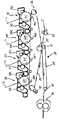
図8は、画像読取装置50の第1面固定読取部151の周辺を示す拡大構成図である。
図8に示すように、プラテンガラス154に対して所定距離離れて対向するベルトガイド機構320を有している。ベルトガイド機構320は、駆動ローラ322と従動ローラ321とに張架されたガイドベルト323を備えている。また、ベルトガイド機構320には、ガイドベルト323の外周面に接触する帯電ローラ324と帯電ローラ324に電圧を印加する電源325とからなる吸着手段たる帯電装置が設けられている。ガイドベルト323は駆動ローラ322によって図中反時計回りに移動する。帯電ローラ324は、ガイドベルト323の原稿吸着領域以外に設けられている。
FIG. 8 is an enlarged configuration diagram showing the periphery of the first surface fixed reading unit 151 of the image reading apparatus 50.
As shown in FIG. 8, the belt guide mechanism 320 is opposed to the platen glass 154 at a predetermined distance. The belt guide mechanism 320 includes a guide belt 323 stretched between a driving roller 322 and a driven roller 321. In addition, the belt guide mechanism 320 is provided with a charging device as an adsorbing means including a charging roller 324 that contacts the outer peripheral surface of the guide belt 323 and a power source 325 that applies a voltage to the charging roller 324. The guide belt 323 is moved counterclockwise in the figure by the driving roller 322. The charging roller 324 is provided outside the document suction area of the guide belt 323.

読取入口ローラ対89によりガイドベルト323へ搬送された原稿MSは、ガイドベルト323から発生する電界によって誘電分極する。そして、この誘電分極によって対向するガイドベルト323上の帯電極性と逆極性の電荷が原稿MSのガイドベルト側に発生し、原稿MSがガイドベルト323上に静電吸着する。ガイドベルト323に静電吸着した原稿MSは、ガイドベルト323によって搬送され原稿読取位置を通過していく。その結果、原稿MSとプラテンガラス154との間に所定距離を有して原稿が搬送される。そして、読取位置を通過して、駆動ローラ322の張架部分へ搬送された原稿MSは、曲率分離によりガイドベルト323から離間し、下流ガイド部材91へ移動する。このように、読取位置において、原稿MSとプラテンガラス154との間に所定距離を有して原稿を搬送することができる。よって、原稿MSがプラテンガラス154と摺擦しないため、原稿MSに付着しているゴミなどがプラテンガラス154との摺擦によってプラテンガラス154の読取位置に付着することがない。これにより、プラテンガラス154の読取位置にゴミなどが付着するのを抑制することができる。   The document MS conveyed to the guide belt 323 by the reading entrance roller pair 89 is dielectrically polarized by an electric field generated from the guide belt 323. Then, due to the dielectric polarization, a charge having a polarity opposite to the charged polarity on the opposing guide belt 323 is generated on the guide belt side of the document MS, and the document MS is electrostatically adsorbed on the guide belt 323. The document MS electrostatically attracted to the guide belt 323 is conveyed by the guide belt 323 and passes through the document reading position. As a result, the document is conveyed with a predetermined distance between the document MS and the platen glass 154. Then, the document MS that has passed through the reading position and is conveyed to the stretched portion of the drive roller 322 moves away from the guide belt 323 due to curvature separation and moves to the downstream guide member 91. In this way, at the reading position, the document can be conveyed with a predetermined distance between the document MS and the platen glass 154. Therefore, since the document MS does not rub against the platen glass 154, dust or the like adhering to the document MS does not adhere to the reading position of the platen glass 154 due to the friction with the platen glass 154. Thereby, it is possible to suppress dust and the like from adhering to the reading position of the platen glass 154.

第1面固定読取部151は、一対の光源151bとこれら光源151bの間に画像読取センサ151aとが設けられている。画像読取センサ151aとしては、CCD(Charge Coupled Device)やCIS(Contact Image Sensor)を用いることができる。原稿MSの画像形成面で最大光量となるように、各光源151bの照射角度が調整されている。   The first surface fixed reading unit 151 includes a pair of light sources 151b and an image reading sensor 151a provided between the light sources 151b. As the image reading sensor 151a, a charge coupled device (CCD) or a contact image sensor (CIS) can be used. The irradiation angle of each light source 151b is adjusted so that the maximum light amount is obtained on the image forming surface of the document MS.

また、プラテンガラス154は、画像読取センサ151aの焦点を中心に鮮明な像を結ぶ光軸上の範囲である被写界深度から、外れた位置に配置されている。すなわち、図9に示すように、画像読取センサ151aから距離L離れたところに画像読取センサ151aの焦点が合っているが、画像読取センサ151aから距離t離れたプラテンガラス154上は、焦点が合っていない。これにより、仮に、プラテンガラス154の読取位置にゴミFが付着しても、プラテンガラス154上のゴミFには、焦点が合っていないので、プラテンガラス154の読取位置上のゴミFは、ぼやけて画像読取センサ151aに読み取られる。その結果、プラテンガラス154の読取位置上のゴミFは、ぼやけた薄い縦スジとなって読取画像に現れ、縦スジを目立ちにくくすることができる。さらに、読取画像の濃度が、原稿画像よりも薄くなるように設定されているなど、読取条件によっては、プラテンガラス154の読取位置上にゴミFが付着していても、縦スジが発生しないようにできる。なお、本実施形態においては、画像読取センサ151aの焦点をガイドベルト323に合わせているが、ガイドベルト323に吸着される原稿MSの画像面に、焦点を合わせてもよい。   Further, the platen glass 154 is disposed at a position deviating from the depth of field that is a range on the optical axis that connects a clear image with the focus of the image reading sensor 151a as a center. That is, as shown in FIG. 9, the image reading sensor 151a is in focus at a distance L from the image reading sensor 151a, but the platen glass 154 at a distance t from the image reading sensor 151a is in focus. Not. Thus, even if dust F adheres to the reading position of the platen glass 154, the dust F on the reading position of the platen glass 154 is not in focus. The image is read by the image reading sensor 151a. As a result, the dust F on the reading position of the platen glass 154 appears as a blurred thin vertical stripe in the read image, and the vertical stripe can be made inconspicuous. Furthermore, depending on the reading conditions, such as the density of the read image is set to be lighter than that of the original image, even if dust F adheres to the reading position of the platen glass 154, vertical stripes do not occur. Can be. In this embodiment, the image reading sensor 151a is focused on the guide belt 323. However, the image reading sensor 151a may be focused on the image surface of the document MS attracted to the guide belt 323.

図10は、プラテンガラス154をガイドベルト323に対して接離させるガラス接離機構180の概略構成図である。
プラテンガラス154は、板状の固定部材171に設けられた長方形状の窓枠に固定されている。スキャナの前側板401と後側板と402とには、固定部材171を支持する後支持部材172aと前支持部材172bとが、それぞれ固定されており、固定部材171は、支持部材172a,172bの支持台部173a,173b上に載置されている。
図11,図12に示すように、後支持部材172aの側面部174aには、2個の長穴175aを有しており、この長穴175aに固定部材171の主走査方向側面から延びる2個のピン171aが遊嵌している。図11,図12では、後支持部材172aについて説明したが、前支持部材172bも同様な構成を有している。
FIG. 10 is a schematic configuration diagram of a glass contact / separation mechanism 180 that contacts and separates the platen glass 154 with respect to the guide belt 323.
The platen glass 154 is fixed to a rectangular window frame provided on the plate-shaped fixing member 171. A rear support member 172a and a front support member 172b for supporting the fixing member 171 are fixed to the front side plate 401 and the rear side plate 402 of the scanner, respectively. The fixing member 171 supports the supporting members 172a and 172b. It is mounted on the base parts 173a and 173b.
As shown in FIGS. 11 and 12, the side surface portion 174a of the rear support member 172a has two elongated holes 175a, and two elongated holes 175a extend from the side surface in the main scanning direction of the fixing member 171. The pin 171a is loosely fitted. 11 and 12, the rear support member 172a has been described, but the front support member 172b has a similar configuration.

先の図10に示すように、後側板402と後支持部材172aとには、第1カム部材188aの第1カム軸187aが回転自在に支持されている。また、前側板401と前支持部材172bとには、第2カム部材188bの第2カム軸187bが回転自在に支持されている。第1カム軸187aの端部には、第1カムプーリ186aが固定されており、第2カム軸187bの端部には、第2カムプーリ186bが固定されている。   As shown in FIG. 10, the first cam shaft 187a of the first cam member 188a is rotatably supported by the rear side plate 402 and the rear support member 172a. The second cam shaft 187b of the second cam member 188b is rotatably supported by the front side plate 401 and the front support member 172b. A first cam pulley 186a is fixed to an end portion of the first cam shaft 187a, and a second cam pulley 186b is fixed to an end portion of the second cam shaft 187b.

また、カム部材188a,188bの下方には、前側板401と後側板402とに軸受を介して回転自在に支持された駆動軸189が設けられている。駆動軸189の後側端部には、第1タイミングプーリ184aと、従動プーリ183とが固定されており、前側端部には、第2タイミングプーリ184bが固定されている。第1カムプーリ186aと第1タイミングプーリ184aとには、第1タイミングベルト185aが巻き回されている。また、第2カムプーリ186bと第2タイミングプーリ184bとには、第2タイミングベルト185bが巻き回されている。また、駆動軸189の従動プーリ183には、駆動タイミングベルト182が巻き回されており、駆動タイミングベルト182は、駆動モータ181のモータ軸181aに固定された駆動プーリ181bにも、巻き回されている。   Further, below the cam members 188a and 188b, a drive shaft 189 that is rotatably supported by a front side plate 401 and a rear side plate 402 via a bearing is provided. A first timing pulley 184a and a driven pulley 183 are fixed to the rear end portion of the drive shaft 189, and a second timing pulley 184b is fixed to the front end portion. A first timing belt 185a is wound around the first cam pulley 186a and the first timing pulley 184a. A second timing belt 185b is wound around the second cam pulley 186b and the second timing pulley 184b. A drive timing belt 182 is wound around the driven pulley 183 of the drive shaft 189, and the drive timing belt 182 is also wound around a drive pulley 181 b fixed to the motor shaft 181 a of the drive motor 181. Yes.

第1カム部材188aまたは第2カム部材188bのいずれか一方には、不図示のフィラーが設けられている。また、このフィラーを検知する不図示のセンサも設けられている。   A filler (not shown) is provided on either the first cam member 188a or the second cam member 188b. Further, a sensor (not shown) for detecting the filler is also provided.

原稿載置台53にセットされた原稿画像の読み取りが終了すると、駆動モータ181を回転させる。駆動モータ181を回転させると、駆動モータ181の駆動力が駆動タイミングベルト182、従動プーリ183を介して駆動軸189に伝達される。駆動軸189から第1タイミングプーリ184a、第1タイミングベルト185a、第1カムプーリ186aを介して、第1カム部材188aを回転させる。同様に、駆動軸189から第2タイミングプーリ184b、第2タイミングベルト185b、第2カムプーリ186bを介して、第2カム部材188bを回転させる。すると、第1カム部材188a、第2カム部材188bが、固定部材171と当接し、固定部材171を上方へ持ち上げる。固定部材171が、第1、第2カム部材188a,188bにより、上方へ持ち上げられると、図12に示すように、固定部材171のピン171aが長穴175aに沿って移動する。これにより、固定部材171に固定されたプラテンガラス154が、ガイドベルト323へ近接する。そして、図13に示す位置まで、固定部材171とともにプラテンガラス154が移動すると、カム部材188に設けられた図示しないフィラーが不図示のセンサによって検知され、駆動モータ181が停止する。   When the reading of the document image set on the document table 53 is completed, the drive motor 181 is rotated. When the drive motor 181 is rotated, the drive force of the drive motor 181 is transmitted to the drive shaft 189 via the drive timing belt 182 and the driven pulley 183. The first cam member 188a is rotated from the drive shaft 189 via the first timing pulley 184a, the first timing belt 185a, and the first cam pulley 186a. Similarly, the second cam member 188b is rotated from the drive shaft 189 via the second timing pulley 184b, the second timing belt 185b, and the second cam pulley 186b. Then, the first cam member 188a and the second cam member 188b come into contact with the fixing member 171 and lift the fixing member 171 upward. When the fixing member 171 is lifted upward by the first and second cam members 188a and 188b, the pin 171a of the fixing member 171 moves along the elongated hole 175a as shown in FIG. As a result, the platen glass 154 fixed to the fixing member 171 approaches the guide belt 323. When the platen glass 154 moves together with the fixing member 171 to the position shown in FIG. 13, a filler (not shown) provided on the cam member 188 is detected by a sensor (not shown), and the drive motor 181 stops.

この時、図14に示すように、プラテンガラス154の移動量をc、帯電装置の吸着可能範囲をHとしたとき、H>L−(t+c)を満たすように、プラテンガラス154を移動させる。これにより、プラテンガラス154の表面を帯電装置の吸着可能範囲をHに入れることができる。プラテンガラス154上の付着物Fは、原稿に付着していたゴミや紙粉である。これらは、レジスト部Cやターン部Dに設けられたガイド部材と摺擦して、摩擦帯電する。そして、これら摩擦帯電した原稿に付着ゴミや紙粉は、原稿がガイドベルト323に吸着する際などに原稿から脱落してプラテンガラス154に付着する。よって、プラテンガラス154上の付着物Fは、通常、摩擦帯電している。このため、プラテンガラス上の付着物Fが、静電的にガイドベルト323へ移動して、ガイドベルト323に付着する。これにより、プラテンガラス154上の付着物が除去される。その結果、ぼやけた薄い縦スジも生じなくなる。
なお、本実施形態においては、プラテンガラス154を固定部材171よりも厚くしている。これは、図8に示すように、上流ガイド部材97や下流ガイド91の一部が、固定部材171と対向している。このため、固定部材171の移動範囲を十分に長くとれない。その結果、プラテンガラス154を固定部材171と同じ厚みにすると、プラテンガラス154の表面を、吸着可能範囲に入れることができない。このため、プラテンガラス154を固定部材171よりも厚くして、固定部材171の移動可能範囲内で、プラテンガラス154の表面が吸着可能範囲に入るようにしている。
At this time, as shown in FIG. 14, when the movement amount of the platen glass 154 is c and the adsorption range of the charging device is H, the platen glass 154 is moved so as to satisfy H> L− (t + c). As a result, the surface of the platen glass 154 can be set to H in the adsorption range of the charging device. The deposit F on the platen glass 154 is dust or paper dust that has adhered to the document. These are rubbed with the guide members provided in the resist part C and the turn part D to be frictionally charged. The dust and paper dust adhering to these frictionally charged documents fall off the document and adhere to the platen glass 154 when the document is attracted to the guide belt 323. Therefore, the deposit F on the platen glass 154 is usually frictionally charged. For this reason, the deposit F on the platen glass moves electrostatically to the guide belt 323 and adheres to the guide belt 323. Thereby, the deposits on the platen glass 154 are removed. As a result, a blurred thin vertical line is not generated.
In the present embodiment, the platen glass 154 is thicker than the fixing member 171. As shown in FIG. 8, the upstream guide member 97 and a part of the downstream guide 91 are opposed to the fixing member 171. For this reason, the moving range of the fixing member 171 cannot be made sufficiently long. As a result, when the platen glass 154 has the same thickness as that of the fixing member 171, the surface of the platen glass 154 cannot be put in the adsorbable range. For this reason, the platen glass 154 is made thicker than the fixing member 171 so that the surface of the platen glass 154 falls within the adsorbable range within the movable range of the fixing member 171.

プラテンガラス154上の付着物を、ガイドベルト323に付着させたら、駆動モータ181を駆動し、カム部材188a,188bを回転させて、プラテンガラス154をガイドベルト323から離間させ、カム部材188a,188bを固定部材171から離間させ、固定部材171が、支持部材172a、172bの支持台部173a,173b上に載置される。   When the deposits on the platen glass 154 adhere to the guide belt 323, the drive motor 181 is driven to rotate the cam members 188a and 188b, thereby separating the platen glass 154 from the guide belt 323 and the cam members 188a and 188b. Is separated from the fixing member 171 and the fixing member 171 is placed on the support base portions 173a and 173b of the support members 172a and 172b.

次に、変形例について、説明する。   Next, a modified example will be described.

[変形例1]
図15は、変形例1の原稿読取装置50aにおける第1面固定読取部151の周辺を示す拡大構成図である。この変形例1の原稿読取装置50aは、プラテンガラスを上下に2枚重ね、上側のプラテンガラス154−2をガイドベルト323に対して、接離させるよう構成したものである。
この場合、下側プラテンガラス154−1は、固定部材171の窓枠に固定されており、固定部材171は、スキャナ150の筐体に移動不能に固定されている。下側プラテンガラス154−1上の上側プラテンガラス154−2は、上下方向に移動可能に設けられている。なお、上側プラテンガラス154−2をガイドベルト323に対して接させるガラス接離機構は、図11〜図13に示した構成と同様である。
[Modification 1]
FIG. 15 is an enlarged configuration diagram illustrating the periphery of the first surface fixed reading unit 151 in the document reading device 50a according to the first modification. The document reading device 50a according to the first modification is configured such that two platen glasses are stacked vertically and the upper platen glass 154-2 is brought into contact with and separated from the guide belt 323.
In this case, the lower platen glass 154-1 is fixed to the window frame of the fixing member 171, and the fixing member 171 is fixed to the housing of the scanner 150 so as not to move. The upper platen glass 154-2 on the lower platen glass 154-1 is provided so as to be movable in the vertical direction. The glass contacting / separating mechanism for bringing the upper platen glass 154-2 into contact with the guide belt 323 is the same as the configuration shown in FIGS.

画像読取時においては、上側プラテンガラス154−2の表面は、画像読取センサ151aの被写界深度から、外れた位置に配置されている。そして、画像読取が終了したら、図16に示すように、上側プラテンガラス154−2をガイドベルト323に近接させ、上側プラテンガラス154−2の表面を、帯電装置の吸着可能範囲Hに入れる。すなわち、移動量をc、上側プラテンガラスの厚さt1、下側プラテンガラスの厚さt2、画像読取センサ151aからガイドベルト323までの距離をLとしたとき、H>L−(t1+t2+c)を満たすように、移動量cが設定される。これにより、原稿搬送時に原稿から脱落して上側プラテンガラス上に付着した紙粉やゴミがガイドベルト323の吸着され、除去される。また、下側プラテンガラス154−1と固定部材171は、スキャナ150に固定され、第1面固定読取部151を覆った状態を保つことができるので、画像読取センサ151aに直接ゴミなどが付着するのを抑制することができる。   At the time of image reading, the surface of the upper platen glass 154-2 is arranged at a position deviating from the depth of field of the image reading sensor 151a. When the image reading is completed, as shown in FIG. 16, the upper platen glass 154-2 is brought close to the guide belt 323, and the surface of the upper platen glass 154-2 is placed in the attractable range H of the charging device. That is, when the movement amount is c, the thickness t1 of the upper platen glass, the thickness t2 of the lower platen glass, and the distance from the image reading sensor 151a to the guide belt 323 is L, H> L− (t1 + t2 + c) is satisfied. As described above, the movement amount c is set. As a result, paper dust and dust that have fallen off from the original and adhered to the upper platen glass during conveyance of the original are adsorbed and removed by the guide belt 323. Further, since the lower platen glass 154-1 and the fixing member 171 are fixed to the scanner 150 and can keep the first surface fixed reading unit 151 covered, dust or the like directly adheres to the image reading sensor 151a. Can be suppressed.

プラテンガラス154上の付着物を、ガイドベルト323に付着させたら、上側プラテンガラス154−2をガイドベルト323から離間させて、上側プラテンガラス154−2を下側プラテンガラス154−1上に重ね合わせる。   After deposits on the platen glass 154 adhere to the guide belt 323, the upper platen glass 154-2 is separated from the guide belt 323 and the upper platen glass 154-2 is superposed on the lower platen glass 154-1. .

また、上側プラテンガラス154−2をガイドベルト323に近接させて、上側プラテンガラス154−2上の付着物をガイドベルト323に吸着させているときに、ADF51が開けられた場合は、上側プラテンガラス154−2をガイドベルト323から離間する方向へ移動させて、下側プラテンガラス154−1上に重ね合わせるようにするのが好ましい。このようにすることで、ADF51が開けられたときに上側プラテンガラス154−2と下側プラテンガラス154−1との間の隙間にゴミが入りこんで、下側プラテンガラス154−1に付着するのを抑制することができる。   Further, when the ADF 51 is opened when the upper platen glass 154-2 is brought close to the guide belt 323 and the adhering matter on the upper platen glass 154-2 is adsorbed to the guide belt 323, the upper platen glass 154-2 is opened. It is preferable to move 154-2 in a direction away from the guide belt 323 so as to overlap the lower platen glass 154-1. In this way, when the ADF 51 is opened, dust enters the gap between the upper platen glass 154-2 and the lower platen glass 154-1 and adheres to the lower platen glass 154-1. Can be suppressed.

[変形例2]
図17は、変形例2の原稿読取装置50bにおける第1面固定読取部151の周辺を示す拡大構成図である。この変形例2の原稿読取装置50bは、ガイドベルト323の表面を清掃するガイドベルト清掃手段たるクリーニングブレード331を設けたものである。なお、図17は、プラテンガラス154をガイドベルト323に近接させたときの様子を示す図である。
図に示すように、下流ガイド部材91と対向する下流上ガイド部材9191aの原稿搬送方向上流端に、ガイドベルト清掃手段たるクリーニングブレード331が貼付されている。クレーニングブレード331の先端は、ガイドベルト表面に当接させている。下流ガイド部材91のクリーニングブレード331とガイドベルト表面との当接位置と対向する位置には、下流ガイド部材91のガイド面から窪ませた集積手段たるゴミ収集部332が設けられている。
[Modification 2]
FIG. 17 is an enlarged configuration diagram illustrating the periphery of the first surface fixed reading unit 151 in the document reading device 50b according to the second modification. The document reading device 50b according to the second modification is provided with a cleaning blade 331 as a guide belt cleaning unit that cleans the surface of the guide belt 323. FIG. 17 is a view showing a state where the platen glass 154 is brought close to the guide belt 323.
As shown in the drawing, a cleaning blade 331 serving as a guide belt cleaning unit is attached to the upstream end of the downstream upper guide member 9191a facing the downstream guide member 91 in the document conveying direction. The tip of the crane blade 331 is in contact with the guide belt surface. A dust collecting portion 332 serving as a collecting unit that is recessed from the guide surface of the downstream guide member 91 is provided at a position opposite to the contact position between the cleaning blade 331 of the downstream guide member 91 and the guide belt surface.

プラテンガラス154上の付着物は、ガイドベルト323に吸着した後、ガイドベルト323により原稿搬送方向下流側へ搬送され、クリーニングブレード331により掻き落とされる。掻き落とされた付着物は、ゴミ収集部332へ落下する。これにより、ガイドベルト323から、原稿へゴミが再付着するのを抑制することができる。なお、図17の例では、クリーニングブレード331を用いたが、クリーニングローラやブラシ等でもよい。   The adhering matter on the platen glass 154 is adsorbed to the guide belt 323, then conveyed to the downstream side in the document conveying direction by the guide belt 323, and scraped off by the cleaning blade 331. The adhered matter scraped off falls to the dust collecting unit 332. Thereby, it is possible to prevent dust from re-adhering to the document from the guide belt 323. In the example of FIG. 17, the cleaning blade 331 is used, but a cleaning roller, a brush, or the like may be used.

また、クリーニングブレード331での清掃時も、帯電ローラ324によりガイドベルト323に電圧を印加している結果、静電的吸着力により、クリーニングブレード331により掻き落とされず、ガイドベルト323とクリーニングブレード331との当接部付近に溜まっていく場合がある。このため、プラテンガラス154上の付着物がガイドベルト323に吸着して、吸着したプラテンガラス154の付着物が、クリーニングブレード331との当接位置に到達するタイミングで帯電ローラ324への電圧印加を停止するようにしてもよい。これにより、ガイドベルト323に対する吸着効果がなくなり、ガイドベルト323とクリーニングブレード331との当接部付近に溜まることなく、クリーニングブレード331によって掻き落とされ、ゴミ収集部332に落下させることができる。   Further, even when cleaning with the cleaning blade 331, the voltage is applied to the guide belt 323 by the charging roller 324. As a result, the cleaning blade 331 is not scraped off by the electrostatic attraction force, and the guide belt 323, the cleaning blade 331, May accumulate near the contact portion. For this reason, the adhering matter on the platen glass 154 is adsorbed to the guide belt 323, and voltage is applied to the charging roller 324 at the timing when the adhering matter on the platen glass 154 reaches the contact position with the cleaning blade 331. You may make it stop. As a result, the adsorbing effect on the guide belt 323 is eliminated, and the guide belt 323 is scraped off by the cleaning blade 331 without being collected in the vicinity of the contact portion between the guide belt 323 and the cleaning blade 331 and can be dropped to the dust collecting unit 332.

また、帯電ローラ324への電圧印加を停止しても、ガイドベルト323に電荷が残っており、ガイドベルト323とクリーニングブレード331との当接部付近に溜まったゴミなどの付着物Fが、クリーニングブレード331によって掻き落とされず、静電吸着力により留まる場合がある。
そこで、図18に示すように、ガイドベルト清掃手段を徐電ブラシ333として、ガイドベルト表面に付着した付着物を徐電する徐電機能を備えてもよい。この場合は、徐電ブラシ333を導電性部材で構成し、徐電ブラシ333が固定されている下流上ガイド部材9191aまたは徐電ブラシ333を接地させる。これにより、ガイドベルト323に静電吸着している帯電したゴミが、徐電ブラシ333に当接することにより徐電される。その結果、より効率的に、ガイドベルト323からゴミをごみゴミ収集部332へ掻き落とすことができる。なお、図18では、徐電ブラシ333を用いた例について説明したが、徐電ローラや徐電機能を持ったブレードなどでもよい。
Even if the voltage application to the charging roller 324 is stopped, the charge remains on the guide belt 323, and the deposit F such as dust collected near the contact portion between the guide belt 323 and the cleaning blade 331 is cleaned. In some cases, the blade 331 may not be scraped off and may remain due to electrostatic attraction.
Therefore, as shown in FIG. 18, the guide belt cleaning means may be a slow current brush 333, which may have a slow current function for slowing the deposits attached to the guide belt surface. In this case, the slow brush 333 is made of a conductive member, and the downstream upper guide member 9191a or the slow brush 333 to which the slow brush 333 is fixed is grounded. As a result, the charged dust electrostatically adsorbed on the guide belt 323 is gradually charged by coming into contact with the slow brush 333. As a result, it is possible to scrape dust from the guide belt 323 to the garbage collection unit 332 more efficiently. In addition, although the example using the slow current brush 333 was demonstrated in FIG. 18, the blade etc. which have a slow current roller, the slow current function, etc. may be sufficient.

また、ガイドベルト323に静電吸着によって搬送された原稿は、ガイドベルト323の駆動ローラ322に張架される部分の図19のDの位置で、曲率分離する。このとき、原稿に付着していたゴミなどが脱落して、下流ガイド部材91のガイド面に落下する場合があった。下流側ガイド部材のガイド面に落下したゴミは、ガイド面上を滑っていく。図8に示すように、プラテンガラス154が、ガイドベルト323から離間する位置にあるとき、下流ガイド部材91のガイド面よりもプラテンガラス154の表面が下方にある。その結果、下流ガイド部材91のガイド面上を滑ってきたゴミが、下流ガイド部材91の原稿搬送方向上流端から落下して、プラテンガラス154上に付着するおそれがあった。
このため、図19に示すように、ゴミ収集部332を、上記曲率分離する箇所Dと対向する位置よりも原稿搬送方向上流側から、クリーニングブレード331とガイドベルト表面との当接位置と対向する位置よりも原稿搬送方向下流側まで配置するようにしてもよい。これにより、クリーニングブレード331により掻き落とされたゴミや、曲率分離により原稿から脱落したゴミを、ゴミ収集部332で回収することができ、プラテンガラス154に付着するのを抑制することができる。また、図19に示すように、ゴミ収集部332の底面を、原稿搬送方向上流側に向かって、下方へ傾斜する傾斜面とするのが好ましい。これにより、クリーニングブレード331により掻き落とされたゴミや、曲率分離により原稿から脱落したゴミが、ゴミ収集部332の原稿搬送方向下流側に集めることができる。
Further, the document conveyed by electrostatic attraction to the guide belt 323 is separated in curvature at the position D in FIG. 19 of the portion of the guide belt 323 stretched by the driving roller 322. At this time, dust or the like adhering to the document may fall off and fall on the guide surface of the downstream guide member 91. The dust falling on the guide surface of the downstream guide member slides on the guide surface. As shown in FIG. 8, when the platen glass 154 is located away from the guide belt 323, the surface of the platen glass 154 is below the guide surface of the downstream guide member 91. As a result, dust that has slipped on the guide surface of the downstream guide member 91 may fall from the upstream end of the downstream guide member 91 in the document conveyance direction and adhere to the platen glass 154.
For this reason, as shown in FIG. 19, the dust collecting portion 332 is opposed to the contact position between the cleaning blade 331 and the guide belt surface from the upstream side in the document conveying direction from the position facing the portion D where the curvature is separated. You may make it arrange | position to the document conveyance direction downstream rather than a position. Accordingly, the dust scraped off by the cleaning blade 331 and the dust removed from the document due to the curvature separation can be collected by the dust collection unit 332 and can be prevented from adhering to the platen glass 154. Further, as shown in FIG. 19, it is preferable that the bottom surface of the dust collecting unit 332 is an inclined surface that is inclined downward toward the upstream side in the document conveying direction. As a result, the dust scraped off by the cleaning blade 331 and the dust removed from the document due to the curvature separation can be collected downstream of the dust collection unit 332 in the document transport direction.

[変形例3]
図20は、変形例3の原稿読取装置50cにおける第1面固定読取部151の周辺を示す拡大構成図である。この変形例3の原稿読取装置50bは、原稿を空気吸引力でガイドベルト323に吸着させる吸着手段を用いたものである。
図20に示すように、ガイドベルト323には、複数の吸引孔323aが設けられている。また、吸引手段たる吸引装置330は、負圧室326と、吸引ダクト327と、不図示の集塵フィルタと、吸引ファン328とで構成されている。負圧室326は、ガイドベルト323の内部に設けられている。負圧室326は、下方に開口した凹部空間が形成されている。開口の大きさは、ガイドベルト323の吸引孔323aが形成されている領域をカバーする大きさである。この開口の回りの開口端面がガイドベルト323のプラテンガラス154と対向する領域と当接している。負圧室326の主走査方向側面には、吸引ダクト327の一端が接続されている。吸引ダクト327の他端は、不図示の集塵フィルタを介して吸引ファン328に接続されている。吸引ファン328が駆動すると吸引ダクト327、負圧室326を介してガイドベルト323の吸引孔323aから空気が吸引される。
[Modification 3]
FIG. 20 is an enlarged configuration diagram illustrating the periphery of the first surface fixed reading unit 151 in the document reading device 50c according to the third modification. The document reading device 50b of Modification 3 uses an adsorbing unit that adsorbs the document to the guide belt 323 with an air suction force.
As shown in FIG. 20, the guide belt 323 is provided with a plurality of suction holes 323a. The suction device 330 serving as a suction means includes a negative pressure chamber 326, a suction duct 327, a dust collection filter (not shown), and a suction fan 328. The negative pressure chamber 326 is provided inside the guide belt 323. The negative pressure chamber 326 has a recessed space that opens downward. The size of the opening is a size that covers a region where the suction hole 323a of the guide belt 323 is formed. An opening end surface around this opening is in contact with a region of the guide belt 323 facing the platen glass 154. One end of a suction duct 327 is connected to the side surface in the main scanning direction of the negative pressure chamber 326. The other end of the suction duct 327 is connected to a suction fan 328 via a dust collection filter (not shown). When the suction fan 328 is driven, air is sucked from the suction holes 323 a of the guide belt 323 through the suction duct 327 and the negative pressure chamber 326.

読取入口ローラ対89によりガイドベルト323へ搬送された原稿MSは、吸引ファン328による吸引力によってガイドベルト323に吸着する。ガイドベルト323に吸着した原稿MSは、ガイドベルト323によって搬送され原稿読取位置を通過していく。その結果、原稿MSとプラテンガラス154との間に所定距離を有して原稿が搬送される。そして、読取位置を通過して、駆動ローラ322の張架部分へ搬送される。駆動ローラ322との張架部分では、吸引力が生じていないので、原稿は、ガイドベルト323から離間し、下流ガイド部材91へ移動する。変形例3のように、空気吸引力で原稿をガイドベルト323に吸着させることでも、読取位置において、原稿とプラテンガラス154との間に所定距離を有して原稿を搬送することができる。よって、原稿がプラテンガラス154と摺擦しないため、原稿に付着しているゴミなどがプラテンガラス154との摺擦によってプラテンガラス154の読取位置に付着することがない。これにより、プラテンガラス154の読取位置にゴミなどが付着するのを抑制することができる。   The document MS conveyed to the guide belt 323 by the reading entrance roller pair 89 is attracted to the guide belt 323 by the suction force of the suction fan 328. The document MS attracted to the guide belt 323 is conveyed by the guide belt 323 and passes through the document reading position. As a result, the document is conveyed with a predetermined distance between the document MS and the platen glass 154. Then, it passes through the reading position and is conveyed to the stretched portion of the drive roller 322. Since no suction force is generated at the stretched portion with the driving roller 322, the document moves away from the guide belt 323 and moves to the downstream guide member 91. As in the third modification, the original can be transported with a predetermined distance between the original and the platen glass 154 at the reading position by adsorbing the original to the guide belt 323 with air suction force. Therefore, since the document does not rub against the platen glass 154, dust or the like adhering to the document does not adhere to the reading position of the platen glass 154 due to the friction with the platen glass 154. Thereby, it is possible to suppress dust and the like from adhering to the reading position of the platen glass 154.

プラテンガラス154上の付着物を除去するときは、図21に示すように、プラテンガラス表面が、吸引装置330の吸引領域内に入るよう、プラテンガラス154をガイドベルト323に近接させる。プラテンガラス154表面が、吸引装置330の吸引領域内に入ると、プラテンガラス154上の付着物が、ガイドベルト323の吸引孔323aから吸引され、除去される。吸引孔323aに吸引されたプラテンガラス154上の付着物は、不図示の集塵フィルタに付着する。この変形例3の構成でも、プラテンガラス154上の付着物が除去されので、ぼやけた薄い縦スジも生じなくなる。   When removing the deposits on the platen glass 154, the platen glass 154 is brought close to the guide belt 323 so that the surface of the platen glass enters the suction region of the suction device 330 as shown in FIG. When the surface of the platen glass 154 enters the suction region of the suction device 330, the deposit on the platen glass 154 is sucked from the suction holes 323a of the guide belt 323 and removed. Deposits on the platen glass 154 sucked into the suction holes 323a adhere to a dust collection filter (not shown). Even in the configuration of the third modified example, the deposits on the platen glass 154 are removed, so that a blurred thin vertical stripe does not occur.

この変形例3においては、吸引孔323aの部分が光を照射したとき、影となって読取画像にノイズとして現れるおそれがある。このため、次のような処理を行って、読取画像に現れる吸引孔323aのノイズ除去する。すなわち、読取時は、ガイドベルト323を一定速度で無端移動させているため、吸引孔323aのノイズは、周期的に読取画像に現れる。また、吸引孔323aの間隔やガイドベルト323の速度などから、吸引孔323aのノイズの周期λや、主走査方向のどの位置の吸引孔323aのノイズが現れるかは、予めわかっている。よって、読取画像から、主走査方向特定の位置で、周期λで現れる画像を検出し、該当する画像を吸引孔323aの影響を受けている画像と特定する。そして、特定した吸引孔323aの影響を受けている画像を構成する画素の画素値を周辺画素の画素値と同じ値に書き換える処理を行う。これにより、読取画像に現れた吸引孔323aのノイズを除去することができる。   In Modification 3, when the portion of the suction hole 323a is irradiated with light, there is a possibility that it will appear as noise in the read image as a shadow. For this reason, the following processing is performed to remove noise from the suction holes 323a appearing in the read image. That is, since the guide belt 323 is moved endlessly at a constant speed during reading, noise in the suction holes 323a periodically appears in the read image. Further, it is known in advance from the interval between the suction holes 323a, the speed of the guide belt 323, etc., the noise period λ of the suction holes 323a and the position of the suction holes 323a in the main scanning direction. Therefore, an image appearing in the period λ at a specific position in the main scanning direction is detected from the read image, and the corresponding image is identified as an image affected by the suction hole 323a. And the process which rewrites the pixel value of the pixel which comprises the image affected by the specified suction hole 323a to the same value as the pixel value of a surrounding pixel is performed. Thereby, the noise of the suction hole 323a appearing in the read image can be removed.

[変形例4]
図22は、変形例4の原稿読取装置50dにおける第1面固定読取部151の周辺を示す拡大構成図である。図に示すように、変形例4の原稿読取装置50dは、プラテンガラス154をスキャナ150に固定し、ベルトガイド機構320をプラテンガラス154に対して接離可能に構成したものである。
[Modification 4]
FIG. 22 is an enlarged configuration diagram illustrating the periphery of the first surface fixed reading unit 151 in the document reading device 50d according to the fourth modification. As shown in the drawing, the document reading device 50d of Modification 4 is configured such that the platen glass 154 is fixed to the scanner 150, and the belt guide mechanism 320 can be brought into contact with and separated from the platen glass 154.

ベルトガイド機構320をプラテンガラス154に対して接離させるベルト接離手段は、次のように構成されている。すなわち、ベルトガイド機構320、帯電ローラ324、電源325、駆動ローラ322を駆動させる不図示の駆動モータが取り付けられた不図示の移動筐体が、ADF51の本体カバー52に上下動可能に支持されている。ベルト接離手段は、この移動筐体を上下動させることで、ベルトガイド機構320をプラテンガラス154に対して接離させる。   The belt contacting / separating means for bringing the belt guide mechanism 320 into and out of contact with the platen glass 154 is configured as follows. That is, a movable housing (not shown) to which a driving motor (not shown) for driving the belt guide mechanism 320, the charging roller 324, the power source 325, and the driving roller 322 is attached is supported by the main body cover 52 of the ADF 51 so as to move up and down. Yes. The belt contacting / separating means moves the moving casing up and down to bring the belt guide mechanism 320 into and out of contact with the platen glass 154.

プラテンガラス154上の付着物を除去する場合は、上記移動筐体を下方へ移動させて静電吸着範囲Hにプラテンガラス154の表面が入るように図中点線の位置まで移動させる。これにより、プラテンガラス154上の付着物が、ガイドベルト323に付着する。ガイドベルト323にプラテンガラス154の付着物が付着したら、移動筐体を上方へ移動させて、ベルトガイド機構320を図中実線の位置まで戻す。変形例4に示すように、ガイドベルト323をプラテンガラス154に対して接離させる構成しても、プラテンガラス上の付着物を吸着手段で除去することができる。   When removing the deposit on the platen glass 154, the moving housing is moved downward to move to the position indicated by the dotted line in the drawing so that the surface of the platen glass 154 enters the electrostatic adsorption range H. Thereby, the deposit on the platen glass 154 adheres to the guide belt 323. When the adherence of the platen glass 154 adheres to the guide belt 323, the movable housing is moved upward to return the belt guide mechanism 320 to the position indicated by the solid line in the figure. As shown in the fourth modification, even if the guide belt 323 is configured to be in contact with or separated from the platen glass 154, the deposits on the platen glass can be removed by the adsorbing means.

図23は、焦点位置とガイドベルト323との位置関係を簡易的に書いたものである。図23に示すように、画像読取センサ151aの焦点は、原稿搬送面に合うのが好ましい。このため、原稿の厚みをDとした場合、画像読取センサ151aからガイドベルト323の表面までの距離Xを、X=L+Dに設定するのが好ましい。しかし、画像読取センサ151aの被写界深度(aの値)が非常に小さい場合、厚紙の時、図中破線で示すように、原稿画像の位置から画像読取センサ151aまでの距離Z2が、L−aよりも小さくなり、原稿画像に焦点が合わない場合がある。その結果、読取画像がボケてしまうおそれがある。   FIG. 23 simply shows the positional relationship between the focal position and the guide belt 323. As shown in FIG. 23, it is preferable that the image reading sensor 151a is focused on the document conveyance surface. For this reason, when the thickness of the document is D, the distance X from the image reading sensor 151a to the surface of the guide belt 323 is preferably set to X = L + D. However, when the depth of field (value of a) of the image reading sensor 151a is very small, as shown by a broken line in the drawing when the paper is thick, the distance Z2 from the position of the original image to the image reading sensor 151a is L It may be smaller than −a, and the original image may not be focused. As a result, the read image may be blurred.

そこで、この変形例4の画像読取装置50dにおいては、搬送原稿の厚みを検知し、その検知結果に基づいて、ベルトガイド機構320を上下に動かすようにしてもよい。
図24は、搬送原稿の厚みを検知する厚み検知手段の一例である。図24は、厚み検知手段として、原稿の透過光量を測定する透過光量測定装置350を用いた構成である。透過光量測定装置350は、ある所定の光量を出力する発光手段351と、その出力された光量を検出する為の受光手段352が、測定対象となる原稿を挟む様に配置され、その原稿の厚み方向の透過光量を測定できるようになっている。また、発光手段351と受光手段352とのそれぞれに対応した制御手段353,354を構成し、搬送されてくるの透過光量を測定し、その光量レベルから原稿の厚みを特定する。厚み検知手段は、原稿搬送経路(図5におけるCやD)に設けられている。
Therefore, in the image reading device 50d of the fourth modification, the thickness of the conveyed document may be detected, and the belt guide mechanism 320 may be moved up and down based on the detection result.
FIG. 24 is an example of a thickness detection unit that detects the thickness of the conveyed document. FIG. 24 shows a configuration in which a transmitted light amount measuring device 350 that measures the transmitted light amount of a document is used as the thickness detecting means. In the transmitted light amount measuring device 350, a light emitting unit 351 for outputting a predetermined light amount and a light receiving unit 352 for detecting the output light amount are arranged so as to sandwich a document to be measured, and the thickness of the document. The amount of transmitted light in the direction can be measured. Further, the control means 353 and 354 corresponding to the light emitting means 351 and the light receiving means 352 are configured, the amount of transmitted light transmitted is measured, and the thickness of the document is specified from the light amount level. The thickness detection means is provided in the document conveyance path (C and D in FIG. 5).

搬送原稿の厚みが、レジスト部Cや、ターン部Dで厚み検知手段によって、検知されると、本体制御部200は、検知した厚みに基づき、ベルトガイド機構320を上下動させて、ガイドベルト323に吸着している原稿画像から画像読取センサ151aまでの距離がLとなるように調整される。これにより、原稿厚みが厚くても、原稿画像に焦点を合わせることができ、高品位な読取画像を得ることができる。   When the thickness of the transported document is detected by the thickness detection means in the registration unit C or the turn unit D, the main body control unit 200 moves the belt guide mechanism 320 up and down based on the detected thickness to guide the guide belt 323. The distance from the original image adsorbed to the image reading sensor 151a is adjusted to be L. As a result, even if the thickness of the document is large, the document image can be focused, and a high-quality read image can be obtained.

また、搬送原稿が切り貼りされている場合など、原稿MSの厚みが副走査方向に均一でない場合もある。そこで、図25に示すように、厚み検知手段で原稿MSの最大厚Dmaxと最小厚Dminとを検知して、画像読取センサ151aからガイドベルト323までの距離Xが、L+{(Dmax+Dmin)/2}となるように、ベルトガイド機構320の移動を制御してもよい。また、Dmax+Dminが、被写界深度(2a)よりも大きいときは、原稿画像に焦点の合わない部分が存在してしまう。よって、この場合は、警告を出し、読取を継続するか否かを図示しない表示部に表示させる。   Further, there are cases where the thickness of the document MS is not uniform in the sub-scanning direction, such as when the transported document is cut and pasted. Therefore, as shown in FIG. 25, the thickness detecting unit detects the maximum thickness Dmax and the minimum thickness Dmin of the document MS, and the distance X from the image reading sensor 151a to the guide belt 323 is L + {(Dmax + Dmin) / 2. }, The movement of the belt guide mechanism 320 may be controlled. Further, when Dmax + Dmin is larger than the depth of field (2a), there is an unfocused portion in the document image. Therefore, in this case, a warning is issued and whether or not to continue reading is displayed on a display unit (not shown).

また、原稿MSの厚さを何点か検知して、原稿MSの厚みをこれら検知した値の平均値としてもよい。この場合は、画像読取センサ151aからガイドベルト323までの距離Xが、X=L+{(D1+D2+・・・・Dn)/2}となるように、ベルトガイド機構320の移動が制御される。原稿MSの副走査方向長さが長い場合は、原稿後端が検知される前に、検知数nに達し、距離Xが算出され、ベルトガイド機構320の移動が制御される。   Alternatively, the thickness of the document MS may be detected at several points, and the thickness of the document MS may be an average value of the detected values. In this case, the movement of the belt guide mechanism 320 is controlled so that the distance X from the image reading sensor 151a to the guide belt 323 becomes X = L + {(D1 + D2 +... Dn) / 2}. When the length of the original MS in the sub-scanning direction is long, the detection number n is reached before the trailing edge of the original is detected, the distance X is calculated, and the movement of the belt guide mechanism 320 is controlled.

また、原稿MSの厚みに応じてリニアでベルトガイド機構320を移動させてもよい。すなわち、切り貼りなどにより他の部分よりも厚みの厚い部分が読取位置に到達したら、ベルトガイド機構320を上方へ移動させる。そして、厚みの厚い部分が読取位置を通過したら、ベルトガイド機構320を下方へ移動させる。これにより、常に、画像読取センサ151aの焦点を原稿画像に合わせることができ、高品位な読取画像を得ることができる。   Further, the belt guide mechanism 320 may be moved linearly according to the thickness of the document MS. That is, when a thicker part than the other part reaches the reading position by cutting and pasting, the belt guide mechanism 320 is moved upward. When the thick portion passes the reading position, the belt guide mechanism 320 is moved downward. As a result, the image reading sensor 151a can always be focused on the document image, and a high-quality read image can be obtained.

また、画像読取装置は原稿MSを読取る為に原稿MSに対して光を照射するが、光源151b,151cによっては時間経過と共に光量が変化したり、明るさにムラが出たりする。それを補正する為にシェーディング補正を行なう。シェーディング補正は、プラテンガラス154の端部に白色板を設け、第1面固定読取部151をこの白色板と対向させ、その白色板を読取り、その読み取りデータに基づいてシェーディング補正をかけるのが一般的である。しかし、本例においては、画像読取センサ151aのセンサの焦点は、ガイドベルト付近にあり、プラテンガラス154の位置は、焦点があっていない。よって、プラテンガラス154の端部に設けられた白色板にも焦点は合っていない。このように焦点が合っていないところの反射光のデータは、焦点があっているところの反射光データと異なるため、正確なシェーディング補正は行えない。   The image reading apparatus irradiates the original MS with light in order to read the original MS. However, depending on the light sources 151b and 151c, the amount of light may change over time or the brightness may become uneven. To correct it, shading correction is performed. For shading correction, a white plate is generally provided at the end of the platen glass 154, the first surface fixed reading unit 151 is opposed to the white plate, the white plate is read, and shading correction is performed based on the read data. Is. However, in this example, the focus of the sensor of the image reading sensor 151a is in the vicinity of the guide belt, and the position of the platen glass 154 is not in focus. Therefore, the white plate provided at the end of the platen glass 154 is not focused. As described above, the reflected light data at the out-of-focus position is different from the reflected light data at the in-focus position, so that accurate shading correction cannot be performed.

そこで、ガイドベルト323を白色にし、このガイドベルト323を読み取り、その読み取りデータに基づいてシェーディング補正をかけるようにしてもよい。具体的には、所定枚数原稿を読み取った後など所定のタイミングでシェーディング補正が実行されると、ベルトガイド機構320が移動して、図26に示すようにガイドベルト323の表面から画像読取センサ151aまでの距離を、画像読取センサ151aから焦点までの距離Lにする。次に、ガイドベルト表面に光を照射し、ガイドベルト表面からの反射光を画像読取センサ151aで読み取り、シェーディングデータを取得する。そして、かかるデータに基づきシェーディング補正を行う。これにより、原稿画像を読み取る位置である焦点があったところのシェーディングデータを取得することができ、正確なシェーディング補正を行うことができる。また、白色板を設ける必要がないため、白色板を設けるものにくらべて、部品点数を減らせることができ、抵コスト化、省スペース化を図ることができる。また、ガイドベルト323の上下方向の僅かな移動でよいので、白色板を移動させるものに比べて、短時間でシェーディング補正を行うことができる。   Therefore, the guide belt 323 may be white, the guide belt 323 may be read, and shading correction may be performed based on the read data. Specifically, when shading correction is performed at a predetermined timing, such as after a predetermined number of documents have been read, the belt guide mechanism 320 moves, and the image reading sensor 151a is moved from the surface of the guide belt 323 as shown in FIG. Is the distance L from the image reading sensor 151a to the focal point. Next, the guide belt surface is irradiated with light, and the reflected light from the guide belt surface is read by the image reading sensor 151a to obtain shading data. Then, shading correction is performed based on such data. As a result, it is possible to acquire shading data at the focal point where the document image is read, and to perform accurate shading correction. In addition, since it is not necessary to provide a white plate, the number of parts can be reduced compared to the case where a white plate is provided, and cost reduction and space saving can be achieved. Further, since the guide belt 323 may be moved slightly in the vertical direction, the shading correction can be performed in a shorter time than that of moving the white plate.

また、画像読取センサ151aの被写界深度の範囲でガイドベルト323を上下に動かしながら、シェーディング補正を行ってもよい。もしくは、画像読取センサ151aの被写界深度の範囲数点でシェーディング補正を行ってもよい。具体的には、シェーディング補正が開始されたら、図27(a)に示すように、ガイドベルト323の表面が被写界深度の上限にくるように、ベルトガイド機構320を移動させる。次に、図27(b)に示すように、ガイドベルト323の表面が被写界深度の下限にくるように、ベルトガイド機構320を移動させる。これにより、画像読取センサ151aの被写界深度の範囲でシェーディング補正のためのデータを得ることができる。これにより、厚さ検知手段と組み合わせることによって、原稿MSの厚さが均一でない場合でも、各位置において正確なシェーディング補正を行うことができ、高品位な読取画像を得ることができる。   Further, the shading correction may be performed while moving the guide belt 323 up and down within the range of the depth of field of the image reading sensor 151a. Alternatively, shading correction may be performed at several points in the depth of field of the image reading sensor 151a. Specifically, when the shading correction is started, the belt guide mechanism 320 is moved so that the surface of the guide belt 323 reaches the upper limit of the depth of field, as shown in FIG. Next, as shown in FIG. 27B, the belt guide mechanism 320 is moved so that the surface of the guide belt 323 is at the lower limit of the depth of field. Thereby, data for shading correction can be obtained within the range of the depth of field of the image reading sensor 151a. Thereby, by combining with the thickness detection means, even when the thickness of the document MS is not uniform, accurate shading correction can be performed at each position, and a high-quality read image can be obtained.

ADF51を開いたとき、下流ガイド部材91と上流ガイド部材97が自重で回動すると、ガイドベルト323が露出する。上述のようにガイドベルト表面をシェーディング補正に用いる場合、ユーザーが露出したガイドベルト323に触れ、ガイドベルト表面が汚れたり、傷ついたりしてしまうおそれがある。ガイドベルト323が汚れたり傷ついたりすると、シェーディング補正を行うための正確なデータが得られなくなり、読取画像が劣化してしまうおそれがある。よって、ADF51が開かれた際、ベルトガイド機構320を上方へ移動させて退避される。これにより、ガイドベルト323が奥まった退避位置に位置するので、ユーザーがガイドベルト323に不用意に触れるのを抑制することができる。その結果、ガイドベルト表面が汚れたり、傷ついたりしてしまうのを抑制することができる。   When the ADF 51 is opened, when the downstream guide member 91 and the upstream guide member 97 are rotated by their own weight, the guide belt 323 is exposed. When the guide belt surface is used for shading correction as described above, the user may touch the exposed guide belt 323 and the surface of the guide belt may become dirty or damaged. If the guide belt 323 becomes dirty or damaged, accurate data for performing shading correction cannot be obtained, and the read image may be deteriorated. Therefore, when the ADF 51 is opened, the belt guide mechanism 320 is moved upward and retracted. Thereby, since the guide belt 323 is located in the retracted position, the user can be prevented from touching the guide belt 323 carelessly. As a result, the surface of the guide belt can be prevented from becoming dirty or damaged.

また、装置の電源が切られた状態でADF51が開けられた際においても、ガイドベルト323が奥まった位置に位置させるため、画像読取動作終了後は、ガイドベルト323を退避位置に移動させるようにするのが好ましい。   Further, even when the ADF 51 is opened with the apparatus turned off, the guide belt 323 is located at the back position so that the guide belt 323 is moved to the retracted position after the image reading operation is completed. It is preferable to do this.

[変形例5]
次に、変形例5について説明する。
上記では、プラテンガラス154またはベルトガイド機構320を上下動させて、プラテンガラスの表面を吸着手段の吸着範囲Hに入れるようにしているが、変形例5においては、プラテンガラス154上に付着した付着物をガイドベルト323に吸着させるときの吸着力を、原稿をガイドベルト323に吸着させるときの吸着力よりも大きくするように制御したものである。
[Modification 5]
Next, Modification 5 will be described.
In the above, the platen glass 154 or the belt guide mechanism 320 is moved up and down so that the surface of the platen glass enters the suction range H of the suction means. However, in the fifth modification, the platen glass 154 or the belt guide mechanism 320 is attached to the platen glass 154. The suction force when the kimono is attracted to the guide belt 323 is controlled to be larger than the suction force when the original is attracted to the guide belt 323.

図28は、変形例5の原稿読取装置におけるプラテンガラス清掃のフローチャートである。
本体制御部200は、画像読取が終了したら(S1のYES)、電源325の帯電ローラ324に印加する電圧を、原稿をガイドベルト323に静電吸着させるときの電圧V1から、プラテンガラス154上の付着物をガイドベルト323に静電吸着させるときの電圧V2に切り替える(S2)。図29(a)に示すように、電源325の電圧がV1のときは、吸着範囲がH1であったが、図29(b)に示すように、電源325の電圧をV2に上げることで、ガイドベルト323の帯電量が増加し、静電吸着範囲H2となり、原稿吸着時の吸着範囲H1よりも広がる。これにより、図29(b)に示すように、プラテンガラス154の表面が、静電吸着範囲H2に入り、プラテンガラス上の付着物Fが、ガイドベルト323へ静電的に付着する。そして、所定時間経過したら、電源325の帯電ローラ324に印加する電圧を、原稿をガイドベルト323に静電吸着させるときの電圧V1へ戻す(S4)。
FIG. 28 is a flowchart of platen glass cleaning in the document reading apparatus according to the fifth modification.
When the image reading is completed (YES in S1), the main body control unit 200 determines the voltage applied to the charging roller 324 of the power source 325 from the voltage V1 when the document is electrostatically attracted to the guide belt 323 on the platen glass 154. The voltage is switched to the voltage V2 when the adhering matter is electrostatically adsorbed to the guide belt 323 (S2). As shown in FIG. 29 (a), when the voltage of the power source 325 is V1, the adsorption range was H1, but as shown in FIG. 29 (b), by increasing the voltage of the power source 325 to V2, The amount of charge of the guide belt 323 increases and becomes the electrostatic adsorption range H2, which is wider than the adsorption range H1 when the original is adsorbed. As a result, as shown in FIG. 29B, the surface of the platen glass 154 enters the electrostatic adsorption range H2, and the deposit F on the platen glass adheres electrostatically to the guide belt 323. When a predetermined time has elapsed, the voltage applied to the charging roller 324 of the power source 325 is returned to the voltage V1 when the document is electrostatically attracted to the guide belt 323 (S4).

変形例5に示すように、吸着手段の吸着力を上げることでも、プラテンガラス154上の付着物を除去することができ、ぼやけた縦すじ画像も抑制することができる。   As shown in the modified example 5, the adhesion on the platen glass 154 can be removed by increasing the adsorption force of the adsorption means, and a blurred vertical stripe image can be suppressed.

また、上記では、吸引手段として、帯電装置を用いた例について説明したが、吸引手段として、変形例3で示した吸引装置330を用いてもよい。   In the above description, an example in which a charging device is used as the suction unit has been described. However, the suction device 330 shown in Modification 3 may be used as the suction unit.

また、本発明は、上述した変形例1〜5に限らず、種々の変形が可能である。例えば、ガラス接離機構180でプラテンガラス154をガイドベルト323に近づけてから、吸着手段の吸着力を上げるようにしてもよい。また、ガラス接離機構180と、変形例3で説明したベルト接離手段とを備え、プラテンガラス154上のゴミを吸着させるとき、ガラス移動機構180でプラテンガラス154をガイドベルトへ近接させるとともに、ベルト接離手段でベルトガイド機構320をプラテンガラス154へ近接させるようにしてもよい。   The present invention is not limited to the first to fifth modifications described above, and various modifications can be made. For example, after the platen glass 154 is brought close to the guide belt 323 by the glass contact / separation mechanism 180, the suction force of the suction means may be increased. Further, the glass contact / separation mechanism 180 and the belt contact / separation means described in Modification 3 are provided, and when the dust on the platen glass 154 is adsorbed, the glass movement mechanism 180 brings the platen glass 154 close to the guide belt, The belt guide mechanism 320 may be brought close to the platen glass 154 by belt contact / separation means.

以上、本実施形態の画像読取装置たる原稿読取装置50は、第1面固定読取部151へ原稿を搬送しながら、読取位置で原稿画像の読み取りを行ういわゆるシートスルー方式の原稿読取装置50である。この原稿読取装置50は、読取位置において、原稿MSと透光部材たるプラテンガラス154との間に所定距離有して原稿MSを搬送する搬送手段たるADF51は、読取位置でプラテンガラス154と対向する表面が原稿搬送方向へ移動するガイドベルト323と、原稿をガイドベルト323に吸着させる吸着手段とを備え、読取位置において、原稿とプラテンガラス154との間に所定距離有して原稿を搬送する。このように、原稿MSとプラテンガラス154との間に所定距離を有して原稿を搬送しているので、原稿MSがプラテンガラス154と摺擦することがない。よって、原稿MSに付着しているゴミなどがプラテンガラス154との摺擦によってプラテンガラス154の読取位置に付着することがない。これにより、プラテンガラス154の読取位置にゴミなどが付着するのを抑制することができる。
また、本実施形態の原稿読取装置50は、プラテンガラス154に付着した付着物を吸着手段によってガイドベルト323に吸着させるよう構成している。これにより、プラテンガラス上の付着物が除去されるので、プラテンガラスの読取位置上に付着した付着物によって縦すじ画像が生じるのを抑制することができる。
As described above, the document reading device 50 as the image reading device of the present embodiment is a so-called sheet-through type document reading device 50 that reads a document image at a reading position while conveying the document to the first surface fixed reading unit 151. . In the document reading device 50, the ADF 51, which is a transport unit that transports the document MS with a predetermined distance between the document MS and the platen glass 154 that is a light transmitting member, faces the platen glass 154 at the reading position. A guide belt 323 whose surface moves in the document conveyance direction and an adsorption means for adsorbing the document to the guide belt 323 are provided, and the document is conveyed with a predetermined distance between the document and the platen glass 154 at the reading position. As described above, since the document is conveyed with a predetermined distance between the document MS and the platen glass 154, the document MS does not rub against the platen glass 154. Therefore, dust or the like adhering to the document MS does not adhere to the reading position of the platen glass 154 due to the rubbing with the platen glass 154. Thereby, it is possible to suppress dust and the like from adhering to the reading position of the platen glass 154.
Further, the document reading apparatus 50 according to the present embodiment is configured such that the adhering matter adhering to the platen glass 154 is adsorbed to the guide belt 323 by the adsorbing means. Thereby, the deposit on the platen glass is removed, so that it is possible to suppress the occurrence of a vertical stripe image due to the deposit adhering to the reading position of the platen glass.

プラテンガラス154に付着した付着物を吸着手段によってガイドベルト323に吸着させる具体的な手段として、プラテンガラス154を、ガイドベルト323に対して接離させる透光部材接離手段たるガラス接離機構180を設けた。プラテンガラス154に付着した付着物を吸着手段によってガイドベルト323に吸着させるとき、プラテンガラス154の表面が、吸着手段の吸着範囲に入るように、プラテンガラス154をガラス接離機構180でガイドベルト323へ近接させる。これにより、プラテンガラス154上の付着物を、ガイドベルト323に付着させることができ、プラテンガラス154の表面から付着物を除去することができる。   As a specific means for adhering the adhering matter adhering to the platen glass 154 to the guide belt 323 by the adsorbing means, a glass contacting / separating mechanism 180 serving as a translucent member contacting / separating means for bringing the platen glass 154 into and out of contact with the guide belt 323. Was provided. When the adhering material adhering to the platen glass 154 is adsorbed to the guide belt 323 by the adsorbing means, the platen glass 154 is guided by the glass contact / separation mechanism 180 so that the surface of the platen glass 154 enters the adsorbing range of the adsorbing means. Close to. Thereby, the deposit on the platen glass 154 can be adhered to the guide belt 323, and the deposit can be removed from the surface of the platen glass 154.

また、変形例1に示すように、プラテンガラス154を2枚重ねにし、ガイドベルト323に近い透光部材たる上側プラテンガラス154−2を、ガイドベルト323に対して接離させるようにしてもよい。これにより、下側プラテンガラス154−1をスキャナ150に固定することができ、スキャナ内部に埃やゴミなどが侵入するのを抑制することができる。   Further, as shown in Modification 1, two platen glasses 154 may be stacked, and the upper platen glass 154-2, which is a translucent member close to the guide belt 323, may be brought into contact with and separated from the guide belt 323. . As a result, the lower platen glass 154-1 can be fixed to the scanner 150, and dust and dust can be prevented from entering the scanner.

変形例1においては、ADF51がスキャナ150に対して開かれたとき、上側プラテンガラス154−2を画像読取時の位置であるガイドベルト323から離間した下側プラテンガラス154−1と重なる位置させるようガラス接離機構180を制御する。これにより、上側プラテンガラス154−2と下側プラテンガラス154−1との隙間にゴミなどが入り込むのを抑制することができる。   In the first modification, when the ADF 51 is opened with respect to the scanner 150, the upper platen glass 154-2 is positioned so as to overlap the lower platen glass 154-1 separated from the guide belt 323 that is the position at the time of image reading. The glass contact / separation mechanism 180 is controlled. Thereby, it is possible to suppress dust and the like from entering the gap between the upper platen glass 154-2 and the lower platen glass 154-1.

また、変形例4に示すように、ガイドベルト323をプラテンガラス154に対して接離させるベルト接離手段を設けて、ガイドベルト323をプラテンガラス154に対して接離させることで、プラテンガラス154に付着した付着物を吸着手段によってガイドベルト323に吸着させるようにしてもよい。プラテンガラス154に付着した付着物を吸着手段によってガイドベルト323に吸着させるときは、プラテンガラス154の表面が、吸着手段の吸着範囲に入るように、ガイドベルト323をベルト接離手段でプラテンガラス154へ近接させる。これにより、プラテンガラス154上の付着物を、ガイドベルト323に付着させることができ、プラテンガラス154の表面から付着物を除去することができる。   In addition, as shown in Modification 4, belt contact / separation means for bringing the guide belt 323 into and out of contact with the platen glass 154 is provided, and the platen glass 154 is brought into and out of contact with the platen glass 154. The adhering matter adhered to the guide belt 323 may be adsorbed by the adsorbing means. When the adhering matter adhering to the platen glass 154 is adsorbed to the guide belt 323 by the adsorbing means, the guide belt 323 is moved by the belt contacting / separating means so that the surface of the platen glass 154 enters the adsorbing range of the adsorbing means. Close to. Thereby, the deposit on the platen glass 154 can be adhered to the guide belt 323, and the deposit can be removed from the surface of the platen glass 154.

また、変形例4においては、ガイドベルト323の表面を用いてシェーディングを行うので、白色板を設ける必要がないため、白色板を設けるものにくらべて、部品点数を減らせることができ、抵コスト化、省スペース化を図ることができる。また、シェーディングを行う際、ガイドベルト323を垂直方向に移動させることで、ガイドベルト表面を第1面固定読取部の焦点に合わせたり、第1面固定読取部の被写界深度範囲内の各位置のシェーディングに用いるデータを取得できたりすることができる。これにより、正確なシェーディングを行うことが可能となる。   Further, in the modified example 4, since the shading is performed using the surface of the guide belt 323, there is no need to provide a white plate, so that the number of parts can be reduced compared to the case where the white plate is provided, and the cost is reduced. And space saving. Further, when performing shading, the guide belt 323 is moved in the vertical direction so that the surface of the guide belt is brought into focus with the first surface fixed reading unit, or within the depth of field range of the first surface fixed reading unit. Data used for position shading can be acquired. As a result, accurate shading can be performed.

また、変形例4においては、厚み検知手段の検知結果に基づいて、ガイドベルト323を移動させる。これにより、厚みの厚い原稿や、副走査方向に厚みの異なる原稿であっても、原稿画像面を第1面固定読取部151の被写界深度内に入るように、原稿を搬送することが可能となる。よって、厚みの厚い原稿や、副走査方向に厚みの異なる原稿であっても高品位な読取画像を得ることができる。   Moreover, in the modification 4, the guide belt 323 is moved based on the detection result of the thickness detection means. As a result, even for a thick document or a document having a different thickness in the sub-scanning direction, the document can be transported so that the document image surface falls within the depth of field of the first surface fixed reading unit 151. It becomes possible. Therefore, a high-quality read image can be obtained even for a thick original or an original having a different thickness in the sub-scanning direction.

また、変形例4においては、ADF51がスキャナ150に対して開かれたとき、ガイドベルト323をプラテンガラス154から離間する方向へ移動させることで、ガイドベルト323にユーザーが不用意に触わることが抑制され、ガイドベルト323の傷や汚れを抑制することができる。   In Modification 4, when the ADF 51 is opened with respect to the scanner 150, the guide belt 323 may be moved away from the platen glass 154 so that the user may carelessly touch the guide belt 323. It is suppressed, and scratches and dirt on the guide belt 323 can be suppressed.

また、変形例5に示すように、プラテンガラス154上に付着した付着物をガイドベルト323に吸着させるときの吸着力を、原稿をガイドベルト323に吸着させるときの吸着力よりも大きくなるよう、制御手段たる本体制御部200が吸着手段を制御することで、プラテンガラス上の付着物を除去してもよい。プラテンガラス154に付着した付着物を吸着手段によってガイドベルト323に吸着させるときは、プラテンガラス154の表面が、吸着範囲に入るよう、吸着力を増加させる。これにより、プラテンガラス154上の付着物を、ガイドベルト323に付着させることができ、プラテンガラス154の表面から付着物を除去することができる。   Further, as shown in the fifth modification example, the adsorption force when adhering the adhering matter adhering to the platen glass 154 to the guide belt 323 is larger than the adsorption force when adsorbing the document to the guide belt 323. The main body control unit 200 as the control means may control the suction means to remove the deposits on the platen glass. When the adhering matter adhering to the platen glass 154 is adsorbed to the guide belt 323 by the adsorbing means, the adsorbing force is increased so that the surface of the platen glass 154 enters the adsorption range. Thereby, the deposit on the platen glass 154 can be adhered to the guide belt 323, and the deposit can be removed from the surface of the platen glass 154.

また、第1面固定読取部151が原稿画像の読み取りを行っていないときに、プラテンガラス上に付着した付着物を吸着手段でガイドベルト323に吸着させる処理を実行する。これにより、読取画像に影響が及ぶことがない。   Further, when the first surface fixed reading unit 151 is not reading a document image, a process of causing the adhering material adhering to the platen glass to be adsorbed to the guide belt 323 by the adsorbing means is executed. Thereby, the read image is not affected.

また、吸着手段たる帯電装置で原稿MSを静電引力でガイドベルト323に吸着させることで、原稿MSをガイドベルト323に吸着させて搬送することができる。また、プラテンガラス上の付着物を静電的にガイドベルト323に付着させることができる。   Further, the document MS can be attracted to the guide belt 323 and conveyed by attracting the document MS to the guide belt 323 by electrostatic attraction using a charging device as an attracting unit. Further, the deposit on the platen glass can be electrostatically adhered to the guide belt 323.

また、変形例3に示すように、吸引手段たる吸引装置で、原稿MSを空気吸引力でガイドベルト323に吸着させても、原稿MSをガイドベルト323に吸着させて搬送することができる。また、プラテンガラス上の付着物を空気吸引力で吸引して、プラテンガラスから除去することができる。   Further, as shown in the third modification, even if the document MS is attracted to the guide belt 323 by air suction force with the suction device as suction means, the document MS can be transported while being attracted to the guide belt 323. Moreover, the deposit on the platen glass can be removed from the platen glass by sucking with air suction.

また、変形例2に示すように、ガイドベルト323の表面を清掃するガイドベルト清掃手段たるクリーニングブレード331を設けることで、ガイドベルト323に付着したプラテンガラス上の付着物が、原稿に付着するのを抑制することができる。   Further, as shown in Modification 2, by providing a cleaning blade 331 that is a guide belt cleaning unit that cleans the surface of the guide belt 323, deposits on the platen glass that adhere to the guide belt 323 adhere to the document. Can be suppressed.

また、変形例2に示すように、ガイドベルト323に吸着したプラテンガラス154上の付着物をクリーニングブレード331で清掃するとき、帯電装置を停止する。これにより、ガイドベルト323の静電的吸着力が減少し、クリーニングブレード331でガイドベルト323に付着した付着物をガイドベルト323から良好に除去することができる。   Further, as shown in the second modification, when the deposit on the platen glass 154 adsorbed to the guide belt 323 is cleaned by the cleaning blade 331, the charging device is stopped. As a result, the electrostatic attraction force of the guide belt 323 is reduced, and the adhering matter adhering to the guide belt 323 with the cleaning blade 331 can be satisfactorily removed from the guide belt 323.

また、変形例2に示すように、クリーニングブレード331によりガイドベルト323から除去された付着物を集積する集積手段たるゴミ収集部332を設けている。これにより、クリーニングブレード331によりガイドベルト323から除去された付着物が、下流ガイド部材91のガイド面に付着し、原稿に付着するのを抑制することができる。また、下流ガイド部材91のガイド面を滑り落ちて、再びプラテンガラス上に付着するのを防止することができる。   In addition, as shown in the second modification, a dust collecting unit 332 is provided as an accumulating unit for accumulating deposits removed from the guide belt 323 by the cleaning blade 331. Thereby, the deposit removed from the guide belt 323 by the cleaning blade 331 can be prevented from adhering to the guide surface of the downstream guide member 91 and adhering to the document. Further, it is possible to prevent the downstream guide member 91 from slipping down and adhering to the platen glass again.

また、ゴミ収集部332をガイドベルト323の原稿剥離位置の下方へ延在させることで、ガイドベルト323から原稿が剥離する際に原稿から脱落したゴミを、ゴミ収集部332で収集することができる。これにより、ガイドベルト323から原稿が剥離する際に原稿から脱落したゴミが、下流ガイド部材91のガイド面を滑り落ちて、プラテンガラス上に付着するのを抑制することができる。   Further, by extending the dust collecting unit 332 below the document peeling position of the guide belt 323, the dust collecting unit 332 can collect the dust that has fallen from the document when the document is peeled off from the guide belt 323. . Thereby, it is possible to prevent dust that has fallen off from the document when the document is peeled from the guide belt 323 from sliding on the guide surface of the downstream guide member 91 and adhering to the platen glass.

また、変形例2に示すように、ガイドベルト清掃手段として、ガイドベルト表面に付着した付着物を徐電する徐電機能を備えた徐電ブラシ333としてもよい。徐電ブラシ333によって付着物が徐電されることで、ガイドベルト323との静電吸着力が低下し、ガイドベルト323から付着物を除去することができる。   Moreover, as shown in the modification 2, it is good also as the slow current brush 333 provided with the slow current function which slows the deposit | attachment adhering to the guide belt surface as a guide belt cleaning means. Since the deposit is gradually electrified by the slow brush 333, the electrostatic adsorption force with the guide belt 323 is reduced, and the deposit can be removed from the guide belt 323.

また、本実施形態の複写機においては、上述の原稿読取装置を備えているので、縦すじが抑制された高品位な画像を複写することができる。   In addition, since the copying machine according to the present embodiment includes the above-described document reading device, it is possible to copy a high-quality image in which vertical stripes are suppressed.

1:画像形成部
2:光書込装置
3K,Y,M,C:プロセスユニット
50:原稿読取装置
53:原稿載置台
54:可動原稿テーブル
55:原稿スタック台
56:ピックアップモータ
57:第1原稿長さ検知センサ
58:第2原稿長さ検知センサ
59:給紙適正位置センサ
61:排紙センサ
63:原稿セットセンサ
65:レジストセンサ
66:中間ローラ対
67:読取入口センサ
72:突き当てセンサ
73:原稿幅センサ
76:給紙モータ
77:読取モータ
78:排紙モータ
79:底板上昇モータ
80:ピックアップローラ
84:給紙ベルト
85:リバースローラ
86:プルアウト駆動ローラ
87:プルアウト従動ローラ
91:下流側ガイド部材
91a 傾斜面
91c,97c:第1位置決め突起
91d,97d:第2位置決め突起
92:読取出口ローラ対
93:第2読取出口ローラ対
95:第2面固定読取部
97:上流側ガイド部材
99:対向ガイド部材
150:スキャナ
151:第1面固定読取部
152:移動読取部
153:画像読取センサ
154:プラテンガラス
155:コンタクトガラス
171:固定部材
180:ガラス接離機構
200:本体制御部
320:ベルトガイド機構
321:従動ローラ
322:駆動ローラ
323:ガイドベルト
323a:吸引孔
324:帯電ローラ
325:電源
326:負圧室
327:吸引ダクト
328:吸引ファン
330:吸引装置
331:クリーニングブレード
332:ゴミ収集部
333:徐電ブラシ
350:透過光量測定装置
1: Image forming unit 2: Optical writing device 3K, Y, M, C: Process unit 50: Document reading device 53: Document placing table 54: Moveable document table 55: Document stacking table 56: Pickup motor 57: First document Length detection sensor 58: second document length detection sensor 59: proper feeding position sensor 61: paper discharge sensor 63: document set sensor 65: registration sensor 66: intermediate roller pair 67: reading entrance sensor 72: abutment sensor 73 : Document width sensor 76: Paper feed motor 77: Reading motor 78: Paper discharge motor 79: Bottom plate raising motor 80: Pickup roller 84: Paper feed belt 85: Reverse roller 86: Pull-out drive roller 87: Pull-out driven roller 91: Downstream side Guide member 91a Inclined surfaces 91c, 97c: first positioning projections 91d, 97d: second positioning projections 92: reading out A pair of mouth rollers 93: a second reading exit roller pair 95: a second surface fixed reading unit 97: an upstream guide member 99: an opposing guide member 150: a scanner 151: a first surface fixed reading unit 152: a moving reading unit 153: an image reading Sensor 154: Platen glass 155: Contact glass 171: Fixing member 180: Glass contact / separation mechanism 200: Main body control unit 320: Belt guide mechanism 321: Driven roller 322: Drive roller 323: Guide belt 323a: Suction hole 324: Charging roller 325 : Power source 326: Negative pressure chamber 327: Suction duct 328: Suction fan 330: Suction device 331: Cleaning blade 332: Dust collector 333: Slow current brush 350: Transmitted light quantity measuring device

特許第3573884号公報Japanese Patent No. 3557384 特開2007−159033号公報JP 2007-159033 A

Claims (18)

読取部を固定して原稿を搬送しながら、読取位置で透光部材を介して原稿画像の読み取りを行う画像読取装置において、
前記読取位置で前記透光部材と対向する表面が原稿搬送方向へ移動するガイドベルトと、前記原稿を前記ガイドベルトに吸着させる吸着手段とを備え、前記読取位置において、原稿と透光部材との間に所定距離有して原稿を搬送する搬送手段と、
前記透光部材上に付着した付着物を、前記吸着手段によって前記透光部材から除去するよう構成したことを特徴とする画像読取装置。
In an image reading apparatus that reads a document image through a translucent member at a reading position while conveying a document while fixing a reading unit,
A guide belt having a surface facing the translucent member at the reading position that moves in a document transport direction; and an adsorbing unit that adsorbs the document to the guide belt. Conveying means for conveying the document with a predetermined distance therebetween;
An image reading apparatus configured to remove deposits adhering to the translucent member from the translucent member by the adsorption means.
請求項1の画像読取装置において、
前記透光部材を、前記ガイドベルトに対して接離させる透光部材接離手段を設けたことを特徴とする画像読取装置。
The image reading apparatus according to claim 1.
An image reading apparatus comprising a translucent member contacting / separating means for contacting and separating the translucent member with respect to the guide belt.
請求項2の画像読取装置において、
前記透光部材が、2枚重なっており、
前記ガイドベルトに近い透光部材を、前記ガイドベルトに対して接離させるよう前記透光部材接離手段を構成したことを特徴とする画像読取装置。
The image reading apparatus according to claim 2.
Two of the light-transmitting members overlap,
The image reading apparatus according to claim 1, wherein the light transmissive member contacting / separating means is configured to bring a light transmissive member close to the guide belt into contact with or separated from the guide belt.
請求項3の画像読取装置において、
前記搬送手段は、前記読取部、前記透光部材を備えたスキャナ部に対して、開閉可能に設けられており、
前記搬送手段が前記スキャナ部に対して開かれたとき、前記ガイドベルトに近い透光部材を前記画像読取時の位置に位置させるよう、前記透光部材接離手段を制御することを特徴とする画像読取装置。
The image reading apparatus according to claim 3.
The conveying means is provided to be openable and closable with respect to the reading unit and a scanner unit including the light transmitting member.
The translucent member contacting / separating unit is controlled so that the translucent member close to the guide belt is positioned at the position at the time of image reading when the transport unit is opened with respect to the scanner unit. Image reading device.
請求項1乃至4いずれかの画像読取装置において、
前記ガイドベルトを前記透光部材に対して接離させるベルト接離手段を設けたことを特徴とする画像読取装置。
The image reading apparatus according to claim 1,
An image reading apparatus comprising belt contacting / separating means for contacting and separating the guide belt with respect to the translucent member.
請求項5の画像読取装置において、
前記ガイドベルトの表面を用いてシェーディングを行うものであって、
前記シェーディングを行う際、前記ガイドベルトを前記読取部の焦点位置へ移動させるよう前記ベルト接離手段を制御することを特徴とする画像読取装置。
The image reading apparatus according to claim 5.
Shading using the surface of the guide belt,
An image reading apparatus that controls the belt contact / separation unit to move the guide belt to a focal position of the reading unit when performing the shading.
請求項5または6の画像読取装置において、
搬送原稿の厚みを検知する厚み検知手段を有し、
前記厚み検知手段の検知結果に基づいて、前記ガイドベルトを移動させるよう前記ベルト接離手段を制御することを特徴とする画像読取装置。
The image reading apparatus according to claim 5 or 6,
Having thickness detecting means for detecting the thickness of the conveyed document;
An image reading apparatus that controls the belt contact / separation unit to move the guide belt based on a detection result of the thickness detection unit.
請求項5乃至7いずれかの画像読取装置において、
前記搬送手段は、前記読取部、前記透光部材を備えたスキャナ部に対して、開閉可能に設けられており、
前記搬送手段が前記スキャナ部に対して開かれたとき、前記ガイドベルトを前記透光部材から離間する方向へ移動させることを特徴とする画像読取装置。
The image reading apparatus according to any one of claims 5 to 7,
The conveying means is provided to be openable and closable with respect to the reading unit and a scanner unit including the light transmitting member.
An image reading apparatus that moves the guide belt in a direction away from the translucent member when the conveying unit is opened with respect to the scanner unit.
請求項1乃至8いずれかの画像読取装置において、
前記透光部材上に付着した付着物を前記ガイドベルトに吸着させるときの吸着力を、前記原稿をガイドベルトに吸着させるときの吸着力よりも大きくなるよう、前記吸着手段を制御する制御手段を備えたことを特徴とする画像読取装置。
The image reading apparatus according to claim 1,
A control means for controlling the suction means so that the suction force when the deposit attached on the translucent member is attracted to the guide belt is larger than the suction force when the original is attracted to the guide belt; An image reading apparatus comprising:
請求項1乃至9いずれかの画像読取装置において、
前記読取部が原稿画像の読み取りを行っていないときに、透光部材上に付着した付着物を、前記吸着手段で前記ガイドベルトに吸着させる処理を実行することを特徴とする画像読取装置。
The image reading apparatus according to claim 1,
An image reading apparatus, wherein when the reading unit is not reading a document image, the adhering material adhering to the translucent member is adsorbed to the guide belt by the adsorbing unit.
請求項1乃至10いずれかの画像読取装置において、
前記吸着手段は、前記原稿を静電引力で前記ガイドベルトに吸着させることを特徴とする画像読取装置。
The image reading apparatus according to claim 1,
The image reading apparatus according to claim 1, wherein the attracting unit attracts the document to the guide belt by electrostatic attraction.
請求項1乃至10いずれかの画像読取装置において、
前記吸着手段は、前記原稿を空気吸引力で前記ガイドベルトに吸着させることを特徴とする画像読取装置。
The image reading apparatus according to claim 1,
The image reading apparatus, wherein the suction unit sucks the document onto the guide belt with an air suction force.
請求項11の画像読取装置において、
前記ガイドベルトの表面を清掃するガイドベルト清掃手段を設けたことを特徴とする画像読取装置。
The image reading apparatus according to claim 11.
An image reading apparatus comprising guide belt cleaning means for cleaning the surface of the guide belt.
請求項13の画像読取装置において、
前記ガイドベルトに吸着したプラテンガラス上の付着物を前記ガイドベルト清掃手段で清掃するとき、前記吸引手段を停止するよう制御することを特徴とする画像読取装置。
The image reading apparatus according to claim 13.
An image reading apparatus that controls to stop the suction unit when the guide belt cleaning unit cleans deposits on the platen glass adsorbed to the guide belt.
請求項13または14の画像読取装置において、
前記ガイドベルト清掃手段によりガイドベルトから除去された付着物を集積する集積手段を備えたことを特徴とする画像読取装置。
The image reading apparatus according to claim 13 or 14,
An image reading apparatus comprising an accumulating unit that accumulates deposits removed from the guide belt by the guide belt cleaning unit.
請求項15の画像読取装置において、
前記ガイドベルト清掃手段は、前記ガイドベルトの原稿剥離位置よりも原稿搬送方向下流側に設けられており、
前記集積手段は、前記ガイドベルト清掃手段によりガイドベルトから除去されて落下してきた付着物を集積するものであって、
前記集積手段を、前記ガイドベルトの原稿剥離位置の下方へ延在させたことを特徴とする画像読取装置。
The image reading apparatus according to claim 15.
The guide belt cleaning means is provided on the downstream side in the document transport direction from the document peeling position of the guide belt,
The accumulating means accumulates deposits that have been removed by dropping from the guide belt by the guide belt cleaning means,
An image reading apparatus characterized in that the stacking means extends below a document peeling position of the guide belt.
請求項13乃至16いずれかの画像読取装置において、
前記ガイドベルト清掃手段は、前記ガイドベルト表面に付着した付着物を徐電する徐電機能を備えたことを特徴とする画像読取装置。
The image reading apparatus according to any one of claims 13 to 16,
The image reading apparatus according to claim 1, wherein the guide belt cleaning unit has a slow current function for gradually slowing the deposits attached to the guide belt surface.
記録材に画像を形成する画像形成手段と、原稿を搬送しながら該原稿の画像を読み取る原稿搬送読取手段とを備え、該原稿搬送読取手段で読み取った画像を該画像形成手段によって該記録材に形成することで、該原稿を複写する複写機において、
上記原稿搬送読取手段として、請求項1乃至17のいずれかの原稿読取装置を用いたことを特徴とする複写機。
An image forming unit for forming an image on a recording material, and a document conveying / reading unit for reading an image of the document while conveying the document, and the image read by the document conveying / reading unit on the recording material by the image forming unit In the copying machine for copying the original,
A copying machine using the document reading device according to claim 1 as the document conveying / reading unit.
JP2009066847A 2009-03-18 2009-03-18 Image reader and copying machine Withdrawn JP2010220090A (en)

Priority Applications (1)

Application Number Priority Date Filing Date Title
JP2009066847A JP2010220090A (en) 2009-03-18 2009-03-18 Image reader and copying machine

Applications Claiming Priority (1)

Application Number Priority Date Filing Date Title
JP2009066847A JP2010220090A (en) 2009-03-18 2009-03-18 Image reader and copying machine

Publications (1)

Publication Number Publication Date
JP2010220090A true JP2010220090A (en) 2010-09-30

Family

ID=42978409

Family Applications (1)

Application Number Title Priority Date Filing Date
JP2009066847A Withdrawn JP2010220090A (en) 2009-03-18 2009-03-18 Image reader and copying machine

Country Status (1)

Country Link
JP (1) JP2010220090A (en)

Cited By (1)

* Cited by examiner, † Cited by third party
Publication number Priority date Publication date Assignee Title
JP2014051383A (en) * 2012-09-10 2014-03-20 Riso Kagaku Corp Image forming apparatus

Cited By (1)

* Cited by examiner, † Cited by third party
Publication number Priority date Publication date Assignee Title
JP2014051383A (en) * 2012-09-10 2014-03-20 Riso Kagaku Corp Image forming apparatus

Similar Documents

Publication Publication Date Title
JP5177683B2 (en) Image reading apparatus and copying machine
JP6037201B2 (en) Sheet conveying apparatus, image reading apparatus, and image forming apparatus
JP2010206632A (en) Image reading apparatus and copying machine
JP6222554B2 (en) Image reading apparatus and image forming apparatus
JP6198123B2 (en) Sheet material conveying apparatus, image reading apparatus, and image forming apparatus
JP5804352B2 (en) Sheet material conveying apparatus, image reading apparatus, and image forming apparatus
JP2004048184A (en) Image reader
JP5754625B2 (en) Image reading apparatus and image forming apparatus
JP6788818B2 (en) Sheet transfer device, image reader and image forming device
JP2009021715A (en) Document reader and image-forming device
JP6179799B2 (en) Image reading apparatus and image forming apparatus having the same
JP5190710B2 (en) Image reading apparatus and copying machine
JP2005001771A (en) Image forming apparatus
JP2004236252A (en) Cleaning apparatus and image forming apparatus equipped with the same
JP2010026050A (en) Image forming apparatus
JP2010220090A (en) Image reader and copying machine
JP5327606B2 (en) Document reading device, document conveying / reading device, and copying machine
JP5477701B2 (en) Document reader and copier
JP2010193004A (en) Image reader, document carrying reader, and copying machine
JP2012232839A (en) Sheet material conveying device, image reading apparatus, and image forming apparatus
JP6152649B2 (en) Image reading apparatus, automatic document feeder, and image forming apparatus
JP6829836B2 (en) Image reader and image forming device
JP6270103B2 (en) Automatic document feeder, document reading system, and copying machine
JP2010219575A (en) Image reading apparatus, original carrier/reader and copying machine
JP5741997B2 (en) Sheet material conveying apparatus, image reading apparatus, and image forming apparatus

Legal Events

Date Code Title Description
A300 Withdrawal of application because of no request for examination

Free format text: JAPANESE INTERMEDIATE CODE: A300

Effective date: 20120605