JP2010220075A - Image forming apparatus, image data processing method, and program - Google Patents
Image forming apparatus, image data processing method, and program Download PDFInfo
- Publication number
- JP2010220075A JP2010220075A JP2009066723A JP2009066723A JP2010220075A JP 2010220075 A JP2010220075 A JP 2010220075A JP 2009066723 A JP2009066723 A JP 2009066723A JP 2009066723 A JP2009066723 A JP 2009066723A JP 2010220075 A JP2010220075 A JP 2010220075A
- Authority
- JP
- Japan
- Prior art keywords
- data
- value
- pixel
- color
- plane
- Prior art date
- Legal status (The legal status is an assumption and is not a legal conclusion. Google has not performed a legal analysis and makes no representation as to the accuracy of the status listed.)
- Pending
Links
- 238000003672 processing method Methods 0.000 title claims description 10
- 238000000034 method Methods 0.000 claims abstract description 105
- 238000006243 chemical reaction Methods 0.000 claims abstract description 40
- 238000009877 rendering Methods 0.000 claims description 65
- 238000013500 data storage Methods 0.000 claims description 23
- 230000005540 biological transmission Effects 0.000 abstract description 16
- 238000010586 diagram Methods 0.000 description 15
- 230000006870 function Effects 0.000 description 15
- 102100035195 Plasminogen-like protein B Human genes 0.000 description 7
- 238000004458 analytical method Methods 0.000 description 3
- 238000004364 calculation method Methods 0.000 description 2
- 239000003086 colorant Substances 0.000 description 2
- 230000001419 dependent effect Effects 0.000 description 2
- 229920000740 poly(D-lysine) polymer Polymers 0.000 description 2
- 230000004044 response Effects 0.000 description 2
- 206010038933 Retinopathy of prematurity Diseases 0.000 description 1
- 230000003287 optical effect Effects 0.000 description 1
- 230000002093 peripheral effect Effects 0.000 description 1
- 238000004321 preservation Methods 0.000 description 1
Images


Abstract
Description
本発明は、ページ記述言語(PDL)で表した入力データをプリント出力用のデータに処理する手段を有した画像形成装置(例えば、プリンタ、デジタル複写機、複合機等)に関し、より詳しくは、半透明描画処理が設定されたPDLの中間(ピクセル)データに対するアクセス効率を向上するための処理手段を有した画像形成装置、当該画像形成装置に用いる画像データ処理方法及びプログラムに関する。 The present invention relates to an image forming apparatus (for example, a printer, a digital copying machine, a multifunction peripheral, etc.) having means for processing input data expressed in a page description language (PDL) into print output data. The present invention relates to an image forming apparatus having a processing means for improving access efficiency to intermediate (pixel) data of PDL for which translucent rendering processing is set, an image data processing method and a program used for the image forming apparatus.
従来から、プリンタ等の画像形成装置では、ホスト装置で作成されたページ記述言語(PDL)によって表した印刷コマンドを受取り、プリント出力用のデータとして処理し、出力に用いる。PDLとしては、PostScriptやPDF(Portable Document Format),PCL(Printer Control Language),XPS(XML(Extensible Markup Language)Paper Specification)等が使用され、画像形成装置は、これらのPDLで記述された印刷コマンドをそれぞれ解析するためのパーサを搭載する。 2. Description of the Related Art Conventionally, an image forming apparatus such as a printer receives a print command expressed by a page description language (PDL) created by a host device, processes it as print output data, and uses it for output. As the PDL, PostScript, PDF (Portable Document Format), PCL (Printer Control Language), XPS (XML (Extensible Markup Language) Paper Specification), or the like is used, and the image forming apparatus uses a print command described in these PDLs. It is equipped with a parser for analyzing each.
PDLの1つであるXPSでは半透明描画という従来のPDLにはない処理が新たに追加されている。半透明描画処理は、半透明で画像同士を重ね合わせる処理で、設定された処理パラメータ(半透明値)に従って処理される。具体的には、重ね合わせる各画像の半透明値を1以下として、通常、重ね合わせたときに全体が1となるように、この処理パラメータが描画オブジェクト毎に設定される。
この半透明描画処理は、PDLを解析した後に得られる中間データをもとにRGB24ビットの多値のピクセルデータに対して行われる処理である。つまり、プリント出力用のデータを得るためには、描画オブジェクト毎にピクセル単位で画像処理(ハーフトーン処理、BG/UCR等)等を施すことが必要で、これらの処理は、RGB24ビットの多値で描画した後に行うが、半透明描画処理もこれらの処理と同様に、RGB24ビットの多値の描画データに対しても行う。
In XPS, which is one of the PDLs, a process that does not exist in the conventional PDL called semi-transparent rendering is newly added. The translucent drawing process is a process of superimposing images with each other in a translucent manner, and is processed according to a set processing parameter (translucent value). Specifically, the semi-transparency value of each image to be superimposed is set to 1 or less, and this processing parameter is usually set for each drawing object so that the whole becomes 1 when superimposed.
This translucent rendering process is a process performed on RGB 24-bit multivalued pixel data based on intermediate data obtained after PDL analysis. That is, in order to obtain print output data, it is necessary to perform image processing (halftone processing, BG / UCR, etc.) and the like for each drawing object in units of pixels. However, the translucent rendering process is also performed on RGB 24-bit multi-value rendering data in the same manner as these processes.
ところで、PDLに設定されているオブジェクト情報は、中間データをもとにRGB24ビットの多値描画を行った後は、各ピクセルとのつながりがなくなってしまうため、その後行う画像処理に用いるために、中間データに記されていたオブジェクト情報を保存しておく必要がある。即ち、描画時にオブジェクト情報は、ピクセル毎に文字で描画されたものか、グラフィックスで描画されたものか、イメージで描画されたものか等を保存し、その後のカラー処理やハーフトーン処理で活用する必要がある。なお、画像処理に用いるために中間データに記されるオブジェクト情報を、各ピクセルに対し属性の決定に用いる情報プレーンの形で保存する方法は、従来から知られている(例えば、特許文献1、参照)。
By the way, the object information set in the PDL is not connected to each pixel after multi-value rendering of RGB 24 bits based on the intermediate data, so that it is used for subsequent image processing. It is necessary to save the object information described in the intermediate data. In other words, when drawing, object information is stored whether it is drawn with characters for each pixel, drawn with graphics, drawn with images, etc., and used in subsequent color processing and halftone processing There is a need to. A method of storing object information written in intermediate data for use in image processing in the form of an information plane used for attribute determination for each pixel is conventionally known (for example,
上記した半透明描画処理のパラメータ(半透明値)もオブジェクト情報の1つとして同様にピクセル毎に保存しておく必要がある。また、XPSの半透明描画処理では半透明描画処理の処理方法によっては、描画先の半透明描画処理の半透明値も保存しておく必要がある。この場合、重ねるデータ(「ソースデータ」という)の半透明値と描画先(「ディスティネーション」という)の半透明値を使用して描画する(下記[発明を実施するための形態]の記載、参照)ので、これもピクセル毎に保存する必要がある。
従って、RGB24ビット多値描画に必要な情報は、色値の他に、ピクセルの属性と半透明値がピクセル毎に必要になる。よって、RGBフルカラーで処理する場合は、1ピクセルあたり、RGB24ビットのほかに、ピクセルの属性と半透明値のためのそれぞれ1バイトを加えて、全部で5バイトのデータをハンドリングしながら処理を行うことになる。
The above-described semi-transparent drawing process parameter (semi-transparent value) must also be stored for each pixel as one piece of object information. Further, in the translucent rendering process of XPS, depending on the processing method of the translucent rendering process, it is necessary to store the translucent value of the rendering destination translucent rendering process. In this case, drawing is performed using the translucent value of the data to be overlaid (referred to as “source data”) and the translucent value of the drawing destination (referred to as “destination”) (described in the following [Description of the Invention], This also needs to be saved for each pixel.
Accordingly, the information necessary for RGB 24-bit multi-value rendering requires pixel attributes and translucent values for each pixel in addition to color values. Therefore, when processing in RGB full color, in addition to RGB 24 bits per pixel, 1 byte is added for each pixel attribute and translucent value, and processing is performed while handling a total of 5 bytes of data. It will be.
上記のように、半透明描画処理が設定されたPDLの中間(ピクセル)データに対し、RGBフルカラーで多値描画処理をする場合、1ピクセルあたり5バイト必要になるため、ピクセル単位に順番に配置すると、1ピクセルは5バイト単位のアクセスになる。コンピュータのCPU(Central Processing Unit)は、現在、通常4バイト(32ビット)のレジスタで構成されるのが普通であるから、1回の読出しで1ピクセル分(5バイトのデータ)にアクセスできないので、通常は1バイトずつアクセスすることになるので5回の命令で1ピクセルのデータの読み出しが可能になる。また、64ビットレジスタで構成されるCPUでも、5バイトずつアクセスすると、必ず境界にまたがる場合が出てくるので効率の悪さは同じである。
本発明は、上記従来技術の問題に鑑みてなされたもので、その目的は、半透明描画処理が設定されたPDLの中間データに対する多値描画処理を経て保存されたピクセルデータへのアクセス効率を向上させることにある。
As described above, when multi-valued rendering processing is performed with RGB full color for PDL intermediate (pixel) data for which translucent rendering processing has been set, 5 bytes are required per pixel, so the pixels are arranged in order. Then, one pixel is accessed in units of 5 bytes. Since a CPU (Central Processing Unit) of a computer is usually composed of a register of 4 bytes (32 bits) at present, it is impossible to access one pixel (5 bytes of data) by one reading. Normally, one byte is accessed, so that one pixel data can be read with five instructions. Further, even in a CPU constituted by a 64-bit register, when 5 bytes are accessed, there is a case where the boundary always crosses the boundary, so the inefficiency is the same.
The present invention has been made in view of the above-described problems of the prior art, and its object is to improve the access efficiency to pixel data stored through multi-level drawing processing for intermediate data of PDL for which semi-transparent drawing processing is set. It is to improve.
本発明は、ページ記述言語を解析して得られる中間形式の画像データを含む中間データを描画オブジェクトが識別できる状態で保存する中間データ保存手段と、中間データ保存手段に保存した中間データから、色値を表すプレーン及び描画オブジェクトを属性に含むピクセルの属性プレーンよりなるピクセルデータを描画する多値描画手段と、多値描画手段で描画したピクセルデータをもとにオブジェクト毎にカラー変換を行うカラー変換手段と、カラー変換手段によって変換された画像データを階調変換する階調処理手段を有した画像形成装置であって、前記中間データ保存手段は、半透明描画処理に用いるパラメータを中間データとして保存し、前記多値描画手段は、中間データ保存手段によって保存された中間データから描画するピクセルデータに半透明描画処理に用いるパラメータを表すプレーンを加えるとともに、描画した各プレーンのピクセルデータを保存する際に、描画した前記ピクセルの属性プレーンと半透明描画処理に用いるパラメータを表すプレーンをまとめて保存するようにしたことを特徴とする。
本発明は、ページ記述言語から中間形式の画像データを解析する工程と、解析された中間形式の画像データを含む中間データを描画オブジェクトが識別できる状態で保存する中間データ保存工程と、中間データ保存工程で保存した中間データから、色値を表すプレーン及び描画オブジェクトを属性に含むピクセルの属性プレーンよりなるピクセルデータを描画する多値描画工程と、多値描画工程で描画したピクセルデータをもとにオブジェクト毎にカラー変換を行うカラー変換工程と、カラー変換工程で変換された画像データを階調変換する階調処理工程を有した画像データ処理方法であって、前記中間データ保存工程は、半透明描画処理に用いるパラメータを中間データとして保存し、前記多値描画工程は、前記中間データ保存工程で保存された中間データから描画するピクセルデータに半透明描画処理に用いるパラメータを表すプレーンを加えるとともに、描画した各プレーンのピクセルデータを保存する際に、描画した前記ピクセルの属性プレーンと半透明描画処理に用いるパラメータをまとめて保存するようにしたことを特徴とする。
The present invention relates to intermediate data storage means for storing intermediate data including image data in an intermediate format obtained by analyzing a page description language in a state in which a drawing object can be identified, and from the intermediate data stored in the intermediate data storage means, Multi-value rendering means that renders pixel data consisting of a plane that represents values and pixel attribute planes that contain rendering objects as attributes, and color conversion that performs color conversion for each object based on pixel data rendered by the multi-value rendering means And an image forming apparatus having gradation processing means for gradation-converting the image data converted by the color conversion means, wherein the intermediate data storage means stores parameters used for the semi-transparent drawing process as intermediate data The multi-value drawing unit draws a picture from the intermediate data stored by the intermediate data storage unit. When the pixel data of each drawn plane is saved, the attribute plane of the drawn pixel and the plane representing the parameter used for the translucent drawing process are collected together. It is characterized by saving.
The present invention includes a step of analyzing intermediate format image data from a page description language, an intermediate data storage step of storing intermediate data including the analyzed intermediate format image data in a state in which a drawing object can be identified, and intermediate data storage From the intermediate data saved in the process, based on the pixel data drawn in the multi-value drawing process and the multi-value drawing process that draws the pixel data consisting of the attribute value plane of the pixel that includes the plane representing the color value and the drawing object as the attribute An image data processing method comprising: a color conversion step for performing color conversion for each object; and a gradation processing step for gradation conversion of image data converted in the color conversion step, wherein the intermediate data storage step is translucent Parameters used for drawing processing are saved as intermediate data, and the multi-value drawing step is saved in the intermediate data saving step In addition to adding a plane representing parameters used for the semi-transparent drawing process to the pixel data to be drawn from the intermediate data drawn, when saving the pixel data of each drawn plane, the attribute plane of the drawn pixel and the semi-transparent drawing process are used. It is characterized in that the parameters to be used are stored together.
本発明によると、半透明描画処理が設定されたPDLの中間(ピクセル)データに対する多値描画処理において、多値描画処理を経て保存されたピクセルデータへのアクセス効率の向上を図ることができる。 According to the present invention, it is possible to improve the access efficiency to the pixel data stored through the multi-value rendering process in the multi-value rendering process for the intermediate (pixel) data of the PDL for which the translucent rendering process is set.
以下に本発明に係る画像形成装置の実施形態を添付した図面を参照して説明する。
図1は、本発明の実施形態に係る画像形成装置のハードウェア構成の概略を示す図である。同図に示すように、画像形成装置は、ホストPC(Personal computer)20から印刷コマンドを受取り、受取った印刷コマンドに従いプリンタエンジン30を動作させるために画像形成装置を構成する各部を制御するコントローラ10と、用紙に画像を印刷するプリンタエンジン30と、ユーザインターフェースとして機能する操作パネル40で構成される。なお、コントローラ10は、後述するように、ホストPC20で作成されたPDLによって表した印刷コマンドを受取り、受取った印刷コマンドをもとにプリント出力用の画像データを生成し、この画像データを用いてプリンタエンジン30を動作させる。また、操作パネル40は、画像形成装置の動作状態等の機器条件をユーザに知らせる表示部と、またユーザが画像形成装置に動作条件を指示する入力を行う入力部を持つ。
Embodiments of an image forming apparatus according to the present invention will be described below with reference to the accompanying drawings.
FIG. 1 is a diagram showing an outline of a hardware configuration of an image forming apparatus according to an embodiment of the present invention. As shown in FIG. 1, the image forming apparatus receives a print command from a host PC (Personal computer) 20 and controls each part of the image forming apparatus to operate the
コントローラ10は、CPU(Central Processing Unit)11、ROM(Read Only Memory)12、RAM(Random Access Memory)13、NV(Nonvolatile)RAM14、ネットワークインターフェース(I/F)15、エンジンI/F16、パネルI/F17の各要素よりなる。
CPU11は、ソフトウェアプログラムの命令を実行する。ROM12は、CPU11が動作するプログラムを格納するメモリである。RAM13は、コントローラソフトが作成するページメモリやCPU11によるソフトウェアの動作に必要なワークメモリとして利用されるメモリである。不揮発性のNVRAM14は、画像形成装置の印刷条件などの設定条件を保存しておくメモリである。
また、ネットワークI/F15は、ネットワーク上に接続されたホストPC20とデータのやり取りを行うためのI/Fである。エンジンI/F16は、プリンタエンジン30との間で印刷指示等のやり取りを行うためのI/Fである。パネルI/F17は、操作パネル40との間でデータの入出力を行うためのI/Fである。
The
The
The network I /
コントローラ10は、ROM12に格納するプログラムの一部に、受取った印刷コマンドをもとにプリント出力用の画像データを生成するためのプログラムを記録し、このプログラムをCPU11が駆動することで、後述する図2及び図3に示す機能を実現する手段を構成する。
なお、上記プログラムを記録する媒体としては、上記ROM12に限らず、HDD(Hard Disk Drive)、CD(Compact Disk)−ROM、MO(Magnet Optical Disk)、DVD(Digital Versatile Disk)等のコンピュータで読み取り可能な記録媒体を用いることができる。また、プログラムを、インターネット等のネットワーク(図示せず)に接続されたコンピュータ上に格納し、ネットワーク経由でダウンロードさせることにより提供するようにしても良い。
The
The medium for recording the program is not limited to the
図2は、画像形成装置(図1)のコントローラのソフトウェア構成を示すブロック図である。
コントローラ10内のソフトウェア構成は、プリンタコントロールシステム部104の制御下に、ホストPC20とデータの交換を行うネットワークI/F部102、操作パネル40の制御を行うパネルI/F部103、受け取った印刷コマンド(印刷データ)をもとにプリント出力用の画像データを生成するPDL部105、プリンタエンジン30に対し印刷指示等を行うエンジンI/F部106を有する。
FIG. 2 is a block diagram showing a software configuration of the controller of the image forming apparatus (FIG. 1).
The software configuration in the
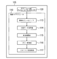
図3は、描画コアモジュールを有するPDL部(図2参照)のモジュール構成を示すブロック図である。
PDL部105は、プリンタコントロールシステム部104を介して受取ったPDLで記述された印刷コマンドを解析するPDLパーサ部120とPDLパーサ部120の解析結果をもとに描画処理及びプリント出力用の画像データへの変換処理を行う描画コアモジュール110よりなる。
描画コアモジュール110は、描画モジュールI/F113、中間データ保存部114、多値描画部115、カラー変換部116、CMYK2値変換部117の各部を有する。
FIG. 3 is a block diagram showing a module configuration of a PDL unit (see FIG. 2) having a drawing core module.
The
The
描画モジュールI/F113は、PDLパーサ部120から解析結果であるテキスト、イメージ、ベクターグラフィックス、描画設定情報を受け取るためのI/Fである。
中間データ保存部114は、テキスト、イメージ、ベクターグラフィックス等の描画オブジェクトを表す描画データと、色値及び半透明描画処理(後記で詳述)の設定等の描画設定情報を保存するための機能部である。
多値描画部115は、中間形式保存部114から指定されたカラースペースでピクセルデータを描画するための機能部である。
カラー変換部116は、多値描画部115によって多値で描画されたデータからデバイスカラー(機器に依存する特性)へ変換するための機能部である。
CMYK2値変換部117は、カラー変換部116で処理されたデバイスカラーをCMYK(C:シアン,M:マゼンタ,Y:イエロー,K:ブラック)2値でハーフトーン処理を行うための機能部である。
なお、多値描画部115のカラースペースは、ページの始めに描画カラースペースとして指定されたものに従う。RGBカラースペースが指定された場合は、RGB各色8ビットで描画される。
The drawing module I /
The intermediate
The
The
The CMYK
Note that the color space of the
描画コアモジュール110を有するPDL部105の構成を示す図3を参照しながら、PDLによって表した印刷コマンドの処理の流れを説明する。
先ず、PDLパーサ120は、印刷コマンドのPDLを解析する。この実施形態では、PDLパーサ120は、PostScript、PDF(Portable Document Format)、PCL(Printer Control Language)、XPS(XML(Extensible Markup Language)Paper Specification)等の各PDLの構文の違いをそれぞれ解析する機能を有し、解析したPDLに対応して、描画コアモジュール110の描画モジュールI/F113をコールする。
描画モジュールI/F113は、イメージ、グラフィックス、文字等の描画オブジェクトを表す描画データと、色値、ブラシ、半透明描画処理(後記で詳述)、線形状等の描画設定情報を得るためのI/Fとして、全てのPDLの描画に対応するI/Fとして機能する。
With reference to FIG. 3 showing the configuration of the
First, the
The drawing module I /
描画モジュールI/F113は、PostScriptを例にすると、以下のような動作で描画コマンドに対応する。
PostScriptでは、例えば、図4に示すような描画コマンドが発行される。即ち、この描画コマンドには、RGBカラースペースで(R,G,B)=(0.5,0.0,0.0)の色で、ページの左下を原点として、左下、右上座標をそれぞれ(100,100)、(200,200)で指定して矩形を描画するコマンドが記述されている。
この描画コマンドに対し、描画モジュールI/F113は、色を設定するI/Fをコールし、その後、矩形領域を設定するために座標を設定するI/Fと塗りつぶし指定するI/Fをコールすることで、描画コマンドに従い矩形を描画することができる。
Taking PostScript as an example, the drawing module I /
In PostScript, for example, a drawing command as shown in FIG. 4 is issued. In other words, this drawing command has a color of (R, G, B) = (0.5, 0.0, 0.0) in the RGB color space, and the lower left and upper right coordinates with the lower left corner of the page as the origin. A command for drawing a rectangle designated by (100, 100) and (200, 200) is described.
In response to this drawing command, the drawing module I /
図5は、このとき描画モジュールI/F113が描画コマンドに応じて行う関数I/Fの設定例を示す図である。
この関数I/Fは、図5に記述するように、図4の描画コマンドに応じて関数シーケンスへの変換を行う。図5の関数シーケンスにおけるsetcolorの第1引数は、RGBカラースペースを指定し、第2から第4引数でRGB各色の色値を0.0から1.0の範囲で指定する。図5の例では、図4の描画コマンドに対応する(0.5,0.0,0.0)が記述されている。
また、図5の関数シーケンスにおけるrectangleは、矩形描画関数で左上座標と右下座標が指定される。図5の例では、図4の描画コマンドに対応する(100,100、200,200)が記述されている。
なお、他の言語も同様に描画モジュールI/F113をコールすることで、描画コマンドに応じた描画が可能である。
FIG. 5 is a diagram illustrating a setting example of the function I / F performed by the drawing module I /
The function I / F is converted into a function sequence in accordance with the drawing command of FIG. 4 as described in FIG. The first argument of setcolor in the function sequence of FIG. 5 specifies the RGB color space, and the second to fourth arguments specify the color value of each RGB color in the range of 0.0 to 1.0. In the example of FIG. 5, (0.5, 0.0, 0.0) corresponding to the drawing command of FIG. 4 is described.
In addition, the rectangle in the function sequence of FIG. 5 is designated as the upper left coordinate and the lower right coordinate by the rectangle drawing function. In the example of FIG. 5, (100, 100, 200, 200) corresponding to the drawing command of FIG. 4 is described.
Similarly, other languages can call the drawing module I /
描画モジュールI/F113がコールされた後、中間データ保存部114により描画モジュールI/F113を介して得られる描画データと描画設定情報は、中間データとしてメモリ上またはファイル上に保存される。
上記した描画モジュールI/F113の動作例で説明すると、setcolor関数では、RGBカラースペースと色値(0.5,0.0,0.0)が設定され、これらを描画設定情報の一つとして得る。
描画データ(イメージ、グラフィックス、文字等の描画オブジェクト)を修飾するためのデータをグラフィックス状態といい、カラースペースと色値は、グラフィックス状態としてメモリ上に保存される。グラフィックス状態には、カラースペースと色値の他に、半透明描画処理のパラメータ、Raster Operation値、線幅などがある。
グラフィックス状態は、図形、イメージ、グラフィックス、文字等の描画オブジェクトを表す描画データと関連付けて保存するときに各オブジェクトに共通なデータ構造を持つ。
After the drawing module I /
Explaining with the operation example of the drawing module I /
Data for modifying drawing data (drawing objects such as images, graphics, and characters) is called a graphics state, and a color space and color values are stored in the memory as a graphics state. The graphics state includes a semi-transparent rendering process parameter, a raster operation value, a line width and the like in addition to a color space and a color value.
The graphics state has a data structure common to each object when saved in association with drawing data representing drawing objects such as graphics, images, graphics, characters, and the like.
図6は、各種描画オブジェクトに共通する、中間データの保存に用いるデータ構造の1例を示す概念図である。なお、図6中の(A)、(B)、(C)は、3種の描画オブジェクトに対しグラフィックス状態(Gstatus)を関連付けて保存するときのデータ構造の例を示したもので、それぞれグラフィックス状態(Gstatus)を表すデータを保存するデータ部601と描画オブジェクトを表す描画データを保存するデータ部603よりなる。
中間データのグラフィックス状態(Gstatus)を表すデータを保存するデータ部601には、描画データを修飾するためのデータとして、カラースペースと色値、線幅、半透明描画処理のパラメータ(半透明値)、Raster Operation値等の描画に共通な設定情報を保存する。図6に示す例では、固定長サイズのGstatusレコードを先頭に、次に描画オブジェクトを表す描画データのID番号がくる。
FIG. 6 is a conceptual diagram showing an example of a data structure used for storing intermediate data common to various drawing objects. In FIG. 6, (A), (B), and (C) show examples of data structures when graphics states (Gstatus) are stored in association with three types of drawing objects, respectively. The
A
ID番号は、描画コマンド(描画オブジェクト)と対応付けられている。
図7は、ID番号と描画コマンドの対応表の1例を示すものである。同図の例では、描画コマンドとして、5種類が示されている。ID=0x00は矩形描画(Rectangle)を、ID=0x01は直線の描画(LineDraw)を、ID=0x02は直線で囲まれた領域の塗りつぶし(LineFill)を、ID=0x03はImageの描画を、ID=0x04は文字の描画を示す。
また、ID番号に続くパッディングバイトとflagの後には、描画コマンドに対応する描画関数の引数、イメージデータ、コードデータ等が保存される。
図5に示した描画モジュールI/F113がrectangle描画コマンドに応じて行う関数I/Fによるコールの例を引くと、このときに保存される中間データ、即ち、図6中の(A)のグラフィックス状態(Gstatus)には、カラースペースと色値が保存され、rectangleの座標はleft=100,top=100,right=200,bottom=200が保存される。なお、ID番号の次のバイトは、パッディングバイトで0が入る。また、flagは、描画コマンドの属性として使われる。属性の例としてRectangleコマンドをClip(描画領域を限定するコマンド)とする場合は、Clipであることを示すビットをONにする。
The ID number is associated with a drawing command (drawing object).
FIG. 7 shows an example of a correspondence table between ID numbers and drawing commands. In the example of FIG. 5, five types of drawing commands are shown. ID = 0x00 is a rectangle drawing (Rectangle), ID = 0x01 is a line drawing (LineDraw), ID = 0x02 is a fill of a region surrounded by a straight line (LineFill), ID = 0x03 is an Image drawing, = 0x04 indicates character drawing.
Further, after the padding byte and flag following the ID number, an argument of a drawing function corresponding to the drawing command, image data, code data, and the like are stored.
When an example of a call by a function I / F performed by the drawing module I /
次に、多値描画部115の動作を説明する。
多値描画部115が行う描画処理は、中間データ保存部114によって保存された中間データをもとにピクセルデータを描画する処理で、プリント出力用の画像データ処理(カラー変換、ハーフトーニング等)の前段で行われる。描画結果のピクセルデータは、点順次に、即ち、ページ画像のピクセルの並び順に、メモリに保存される。
具体的には、設定されたカラースペースに従って各色8ビット(多値)の色値を表すカラープレーン、各ピクセルの属性をカラープレーンに対応付けて表すピクセル属性プレーン、半透明描画処理に用いる半透明値を表すディスティネーション透過プレーンの各プレーンのピクセルデータを点順次に描画する。
Next, the operation of the
The rendering process performed by the
Specifically, according to the set color space, a color plane that represents an 8-bit (multi-value) color value for each color, a pixel attribute plane that associates the attribute of each pixel with the color plane, and translucent used for translucent rendering processing The pixel data of each plane of the destination transmission plane representing the value is drawn dot-sequentially.
図8は、中間データをもとに多値描画部115によって描画されるピクセルデータの各プレーンのデータ構成を示す概念図である。
図8(A)に示すカラープレーンは、ページ領域を描画するピクセルについて、点順示フォーマットで色値を保存する。同図に示す例は、カラースペースがRGB(RはRed、GはGreen、BはBlue)の場合で、RGB(各色8ビット)のピクセル色値が点順示に保存される。このカラープレーンは、同図に示すように、1ピクセル当たり4バイトを確保して実施する。なお、図8(A)中のPはパッティングバイトであり、カラースペースがRGBの場合には、Pの値は0が埋められる。なお、カラースペースがCMYKの場合4バイトを全部ピクセル色値で使用する。
FIG. 8 is a conceptual diagram showing a data configuration of each plane of pixel data drawn by the
The color plane shown in FIG. 8A stores color values in a dot order format for pixels for drawing a page area. In the example shown in the figure, the color space is RGB (R is Red, G is Green, and B is Blue), and RGB (8 bits for each color) pixel color values are stored in a dot order. As shown in the figure, this color plane is implemented by securing 4 bytes per pixel. Note that P in FIG. 8A is a putting byte. When the color space is RGB, 0 is padded with the value of P. When the color space is CMYK, all 4 bytes are used as pixel color values.
図8(B)に示すピクセル属性プレーンは、上記で説明した中間データ(図6に示したデータ構造、参照)に示される描画オブジェクトを表す描画データがピクセルデータを描画するときに消失してしまうと、各描画オブジェクトの特性をプリント出力用の画像データに反映できなくなるので、ピクセルの属性として描画オブジェクトを関連付けるために作られる。
この実施形態では、各ピクセルの属性を表すデータ値(図8(B)中に「A」として示す)を8ビットで持つ。8ビットであれば各ビットで8種類の属性値を表現できる。属性の使用用途は描画されたピクセルが文字、イメージ、グラフィックス等の描画オブジェクトのどれに属するかを区別するために使用される。
図8(C)に示す半透明描画処理に用いるディスティネーション透過プレーンは、描画先(ディスティネーション)の半透明描画処理に用いる半透明値(図8(C)中に「T」として示す)を8ビットで持つ。なお、透過プレーンの使用方法については、後記で詳細に説明する。
The pixel attribute plane shown in FIG. 8B disappears when drawing data representing the drawing object shown in the intermediate data (see the data structure shown in FIG. 6) described above is drawn. Since the characteristics of each drawing object cannot be reflected in the image data for print output, it is created to associate the drawing object as a pixel attribute.
In this embodiment, the data value (indicated as “A” in FIG. 8B) representing the attribute of each pixel has 8 bits. If it is 8 bits, 8 types of attribute values can be expressed by each bit. The attribute usage is used to distinguish whether a drawn pixel belongs to a drawing object such as a character, an image, or a graphic.
The destination transparent plane used for the translucent drawing process shown in FIG. 8C has a translucent value (indicated as “T” in FIG. 8C) used for the translucent drawing process of the drawing destination (destination). It has 8 bits. The method of using the transmission plane will be described in detail later.
図8の各プレーンは、メモリが1ページ分確保できる場合には、図6に示したデータ構造で保存された中間データを保存された順番に取り出して、指定されたアドレス(座標データ)に書込むことにより作られる。
図6に示したデータ構造では、描画コマンド(ID番号)を識別することで、ピクセル属性としての描画オブジェクトとピクセルのアドレス(座標データ)とが得られ、これらのデータに基づいて、ピクセル属性プレーンにデータを書込む。同時に、当該描画コマンドのGstatus(グラフィックス状態)からカラースペースと色値、半透明描画処理のパラメータとしての半透明値、Raster Operation値等が得られ、これらのデータに基づいて、カラープレーン、ディスティネーション透過プレーンそれぞれにデータを書込む。このとき、カラープレーン上で表す色値をindex値で表すようにする形態で実施することができる。なお、このindex値は、カラールックアップテーブルによって色値と関連付けておくことで復元できる。index値を採用することで、処理するデータ量を低減できる。
また、書き込む際に、以下に示すRaster Operation又は半透明描画処理を行う。
Each plane in FIG. 8 takes out the intermediate data saved in the data structure shown in FIG. 6 in the order in which it is saved when one page of memory can be secured, and writes it to the specified address (coordinate data). It is made by putting.
In the data structure shown in FIG. 6, by identifying a drawing command (ID number), a drawing object as a pixel attribute and a pixel address (coordinate data) are obtained. Based on these data, a pixel attribute plane is obtained. Write data to. At the same time, a color space and color value, a translucent value as a parameter of the translucent rendering process, a raster operation value, and the like are obtained from the Gstatus (graphics state) of the rendering command. Write data to each Nation transparent plane. At this time, the color value represented on the color plane can be expressed as an index value. This index value can be restored by associating it with a color value by a color lookup table. By adopting the index value, the amount of data to be processed can be reduced.
Further, when writing, the following Raster Operation or translucent drawing process is performed.
ROP(Raster Operation)は、Windows(登録商標)OS(Operating System)のグラフィックスエンジンで使われる画像処理であり、同じ領域に重なる図形の色値をRGB各色毎にビット演算をする処理である。ビット演算は、OR,XOR,ANDがある。
他方、半透明描画処理は、Windows(登録商標) Vista(登録商標)でサポートされるXPSやPDFで使われる画像処理で、同じ領域に重なる色値の透過割合を0%から100%で指定することで半透明描画する処理である。
通常、ROPと半透明描画処理が同時に使われることはないが、使われていてもよい。
ROP (Raster Operation) is an image process used in a graphics engine of Windows (registered trademark) OS (Operating System), and is a process of performing bit operation on color values of a graphic overlapping the same area for each RGB color. Bit operations include OR, XOR, and AND.
On the other hand, the translucent rendering process is an image process used in XPS or PDF supported by Windows (registered trademark) Vista (registered trademark), and specifies the transmission ratio of color values overlapping the same area from 0% to 100%. This is a process of rendering translucent.
Usually, ROP and translucent drawing processing are not used at the same time, but they may be used.
ROPが行われる場合は、ディスティネーション透過プレーン(図8(C)、参照)には書込みは行わない。また、Gstatus(グラフィックス状態)から得られるRaster Operation値(ID)によって、重なる画像(ピクセル)の色値同士でOR,XOR,ANDのビット演算を実施し、演算結果をカラープレーンの当該ピクセルのRGB色値(各色8ビット)データとして書込む。
なお、Gstatus(グラフィックス状態)に保存されているROPを指定するIDは、0〜255までの256通りあり、それぞれどのようなビット演算が行うか予め定義されている。この定義に従ってRGB各色毎にソースとディスティネーションのビット演算を実施する。
また、ビット演算を実施した後に、ピクセル属性プレーンに描画したピクセルのオブジェクト情報(文字、イメージ、グラフィックス)をピクセルの属性として点順次に書込む。
When ROP is performed, writing is not performed on the destination transmission plane (see FIG. 8C). In addition, the OR, XOR, and AND bit operations are performed between the color values of the overlapping images (pixels) by using the raster operation value (ID) obtained from Gstatus (graphics state), and the calculation result is calculated for the corresponding pixel of the color plane. Write as RGB color value (8 bits for each color) data.
Note that there are 256 IDs from 0 to 255 that designate ROPs stored in Gstatus (graphics state), and each bit operation is defined in advance. In accordance with this definition, bit calculation of the source and destination is performed for each color of RGB.
In addition, after performing the bit operation, the pixel object information (character, image, graphics) drawn on the pixel attribute plane is written dot-sequentially as the pixel attribute.
半透明描画処理は、次に示す処理方法で実施する。
この実施形態で採用する半透明描画処理は、大別すると、描画対象のソースデータに対してのみ処理条件を設定する場合と、ソースデータ(重ねるデータ)と描画後のディスティネーションデータ(描画先のデータ)の両方に処理条件を設定する場合がある。
前者の場合、ソースとディスティネーションそれぞれのピクセルの色値を、ソース:S、ディスティネーション:Dとし、ソースの半透明値(0から1の間をとる)を半透明値:αとすると、半透明描画処理後の色値:NewDは、下記式(1)に基づいて算出することができる。
NewD = S*α+(1−α)*D ・・・式(1)
この半透明描画後の色値を算出する処理は、RGBの各色毎に行う。また、上記のようにソースデータに対してのみ、ソースα処理条件を設定する場合、ディスティネーション透過プレーン(図8(C)、参照)は、使用しない。
The translucent drawing process is performed by the following processing method.
The semi-transparent rendering process employed in this embodiment can be broadly divided into the case where processing conditions are set only for the source data to be rendered, the source data (the data to be overlaid), and the destination data after rendering (the rendering destination Processing conditions may be set for both (data).
In the former case, if the color value of each pixel of the source and destination is source: S, the destination: D, and the translucency value of the source (between 0 and 1) is translucent value: α, The color value NewD after the transparent drawing process can be calculated based on the following formula (1).
NewD = S * α + (1−α) * D (1)
The process of calculating the color value after the semi-transparent drawing is performed for each color of RGB. Further, when the source α processing condition is set only for the source data as described above, the destination transmission plane (see FIG. 8C) is not used.
また、ソースデータと描画後のディスティネーションデータの両方に処理条件を設定する場合、
As:ソースの半透明値
Ad:ディスティネーション半透明値
Ad’:描画後のディスティネーション半透明値
Cs:ソース色値
Cd:ディスティネーション色値
Cd’:描画後のディスティネーション色値
とすると、Ad’及びCd’は、それぞれ例えば下記式(2)及び式(3)に基づいて算出することができる。
Ad’ = (1−As)*Ad+As ・・・式(2)
Cd’ = ((1−As)*Ad*Cd+As*Cs)/Ad’ ・・・式(3)
Also, when setting the processing conditions for both the source data and the destination data after drawing,
As: Source translucent value Ad: Destination translucent value Ad ′: Destination translucent value after drawing Cs: Source color value Cd: Destination color value Cd ′: Destination color value after drawing Ad 'And Cd' can be calculated based on, for example, the following formulas (2) and (3), respectively.
Ad ′ = (1-As) * Ad + As (2)
Cd ′ = ((1−As) * Ad * Cd + As * Cs) / Ad ′ (3)
上記式(2)に基づいて算出される描画後のディスティネーション半透明値Ad’は、ディスティネーション透過プレーン(図8(C)、参照)の該当ピクセルに描画されることになる。
ソースの半透明値Asは、Gstatus(グラフィックス状態)に設定されている。
多値描画部115が中間データの描画オブジェクトをページメモリに描画する場合、Gstatusに設定されている描画対象オブジェクトの半透明描画処理に用いる半透明値、色値を取り出して、またディスティネーションのカラープレーンに設定されている色値、同じくディスティネーション透過プレーンに設定されているディスティネーション半透明値を使用して、新たなディスティネーション色値とディスティネーション半透明値を計算して、算出値によりそれぞれの値を更新する。
なお、半透明描画処理の処理方法は、同一ページを処理する場合1つの方法に定められているので、複数の処理方法が混在することはない。
The destination translucent value Ad ′ after drawing calculated based on the above equation (2) is drawn on the corresponding pixel of the destination transmission plane (see FIG. 8C).
The source translucency value As is set to Gstatus (graphics state).
When the
Note that, since the processing method of the translucent rendering process is determined as one method when processing the same page, a plurality of processing methods will not be mixed.
以上の説明は、図8(A)に示すカラープレーンへRGBデータを書込む多値描画処理の場合を説明したが、CMYK各色8ビットで描画する場合は、図8(A)に示すカラープレーンにおける1ピクセル当たりパッディングバイトPを有するPRGB32ビットで表現していたものをCMYK32ビットで描画するように置き換えればよい。つまり、パッティングバイトPは設ける必要はない。なお、グレースケールの場合は1ピクセル当たり8ビットで描画することになる。
また、中間データのGstatusに半透明描画処理に用いる半透明値があるか否かを確認することにより半透明描画処理の有無を判定する手段を備え、この半透明描画処理判定手段によって半透明描画処理がないと判断された場合に、色値を表すプレーンとして、多値をCMYK2値形式の色値で表す描画処理を行うようにしてもよい。
In the above description, the case of multi-value drawing processing in which RGB data is written to the color plane shown in FIG. 8A has been described. However, when drawing with 8 bits for each color of CMYK, the color plane shown in FIG. In this case, what is expressed by 32 bits of PRGB having padding bytes P per pixel in the above may be replaced with drawing by 32 bits of CMYK. That is, it is not necessary to provide the putting bit P. In the case of gray scale, drawing is performed with 8 bits per pixel.
In addition, it is provided with means for determining whether or not there is a semi-transparent drawing process by checking whether or not the Gdata of the intermediate data has a semi-transparent value used for the semi-transparent drawing process. When it is determined that there is no processing, a rendering process may be performed in which multivalues are represented by color values in the CMYK binary format as a plane representing color values.
ここで、多値描画処理によって保存されるピクセルデータの保存方法について説明する。
この種の画像形成装置では、多値描画処理によって、色値の他に、ピクセルの属性と半透明値をピクセルデータとして生成し、これらのデータをプリント出力に用いるために保存する。このピクセルデータの保存方法は、従来技術のように、ピクセル単位に順番に配置すると、1ピクセルは5バイト単位のアクセスになってしまい、4バイト(32ビット)のレジスタで構成されるCPUにとってアクセス効率の低下を招くことは、先に述べたとおりである。
そこで、プリント出力に用いる際、保存したピクセルデータを読出す時のアクセス効率を高めることができる保存方法をこの実施形態では採用する。
Here, a storage method of pixel data stored by the multi-value drawing process will be described.
In this type of image forming apparatus, pixel attributes and translucent values are generated as pixel data in addition to color values by multi-value drawing processing, and these data are stored for use in print output. In this pixel data storage method, when the pixels are arranged in order as in the prior art, one pixel is accessed in units of 5 bytes, which is accessed by a CPU composed of 4 bytes (32 bits) registers. As described above, the efficiency is reduced.
Therefore, in this embodiment, a storage method that can improve the access efficiency when reading the stored pixel data when used for print output is adopted.
ピクセルデータを保存する形態として、概念的には3種の別プレーンとする例について、図8を参照して説明した。ただ、実際の各プレーンの保存形態は、別の記憶領域を利用して保存する必要はなく、プレーンを統合して保存する方法を採ることが可能である。
この実施形態では、先ず、カラープレーンには、図8(A)に示したように、1ピクセルあたり4バイトで点順次に色値を保存するので、4バイト構成のレジスタを持つCPUからのアクセスに都合がよい。よって、カラープレーンは、図8(A)に示したフォーマットで保存する方法を採用する。
As an example of storing pixel data, an example of conceptually using three different planes has been described with reference to FIG. However, the actual storage mode of each plane does not need to be stored using a separate storage area, and a method of storing planes in an integrated manner can be adopted.
In this embodiment, first, as shown in FIG. 8A, color values are stored dot-sequentially at 4 bytes per pixel in the color plane, so access from a CPU having a 4-byte configuration register. Convenient to. Therefore, the color plane is stored in the format shown in FIG.
また、ピクセル属性プレーンには、ピクセル属性としてのオブジェクト情報(文字、イメージ、グラフィックス)を保存するために必要な容量として、1ピクセルあたり1バイトを確保できればよく、ディスティネーション透過プレーンには、ディスティネーション半透明値を保存するために必要な容量として、1ピクセルあたり1バイトを確保できればよい。よって、ピクセル属性とディスティネーション透過の両プレーンをまとめて1ピクセルあたり2バイトで保存する統合プレーンを用いる方法を採用する。この方法によると、1回のアクセスで、ピクセル属性としてのオブジェクト情報とディスティネーション半透明値の2ピクセル分を取得できる。
図9は、ピクセル属性とディスティネーション透過の両プレーンを統合したフォーマットの概念図を示す。同図に示すように、統合プレーンには、ページ領域を描画するピクセルについて、点順示フォーマットでピクセル属性Aとディスティネーション半透明値Tをまとめて保存する。
Further, the pixel attribute plane only needs to secure 1 byte per pixel as a capacity necessary for storing object information (characters, images, graphics) as the pixel attribute. It is only necessary to secure 1 byte per pixel as a capacity necessary for storing the nation translucency value. Therefore, a method of using an integrated plane that stores both the pixel attribute plane and the destination transmission plane together at 2 bytes per pixel is adopted. According to this method, it is possible to acquire object information as a pixel attribute and a destination translucent value of two pixels in one access.
FIG. 9 is a conceptual diagram of a format in which both the pixel attribute plane and the destination transmission plane are integrated. As shown in the drawing, the pixel attribute A and the destination translucent value T are collectively stored in a dot order format for the pixels in which the page area is drawn in the integrated plane.
上記のピクセルデータの保存方法をとることで、カラープレーンの4バイトと統合(ピクセル属性+ディスティネーション半透明値)プレーンの2バイトを1ピクセル分としてアクセスを行うことができる。つまり、1.5回の読出しコマンドで1ピクセルデータの読出しができるようになって、少ないコマンド数でピクセルデータの読出しができるために、処理効率を高めることができる。
なお、カラープレーンに4バイトを確保するので、CMYKの場合についても、1.5回の読出しコマンドで1ピクセルデータの読出しができることに変わりがなく、RGB,CMYKいずれも効率よくハンドリングでき、3種のプレーンに保存されたピクセルデータを、以後に行うカラー変換、ハーフトーニング等のプリント出力用の画像データの処理の効率化が図れる。
By using the pixel data storage method described above, it is possible to perform access by using 4 bytes of the color plane and 2 bytes of the integrated (pixel attribute + destination translucent value) plane as one pixel. That is, one pixel data can be read out by 1.5 times of read commands, and pixel data can be read out with a small number of commands, so that the processing efficiency can be improved.
In addition, since 4 bytes are secured in the color plane, even in the case of CMYK, there is no change in that one pixel data can be read with a read command of 1.5 times, and both RGB and CMYK can be handled efficiently. It is possible to improve the efficiency of processing image data for print output such as color conversion and halftoning performed on the pixel data stored in the plane.
次に、バンディング処理について説明する。
上記の説明で多値描画部115が処理に必要なメモリ容量として、1ページ分確保できるものとして説明したが、1ページ分のメモリ容量が確保できない場合には、バンディング処理という方法によって描画処理を行う。
図10は、バンディング処理におけるバンドデータとページデータとの関係を説明する概念図である。バンディング処理は、コントローラ10が1ページ分のメモリ容量が確保できない場合に、図10に示すように、ページデータを高さ方向に複数に分割し、分割したバンドデータ単位でメモリ容量を確保し(図10の例では、高さ1024のバンドメモリを確保)、処理を行うことで、ページデータの処理を可能にする方法である。
Next, banding processing will be described.
In the above description, the
FIG. 10 is a conceptual diagram illustrating the relationship between band data and page data in banding processing. In the banding process, when the
バンディング処理では、多値描画部115は、描画処理に必要な中間データを取得する際に、バンド単位でメモリにアクセスし、取得した中間データを確保したバンドメモリに保存することで描画処理を実行する。バンドメモリに保存することができた中間データ以外のバンドデータは、圧縮するか、ハードディスク(不図示)等に退避しておく。圧縮した形で処理を待つバンドデータは、描画要求があった時点で圧縮を解凍してバンドメモリ上にロードする。ハードディクス退避しておいた場合にも描画要求があった時点でメモリ上にロードする。描画が終了し、次のバンド描画要求があった時点で圧縮するか、又はハードディスクへ保存するような処理を行う。
In the banding process, when the
中間データ(図6に示したデータ構造、参照)をもとにバンディング処理で描画を行う際、各描画オブジェクトの座標データから各バンドデータにクリップしてバンドメモリに描画する。
描画結果としてバンドメモリに保存するピクセルデータは、図8及び図9の例に示したフォーマットになるが、バンド毎に違うフォーマットを適用できるようにすることによりメモリ容量を節約でき、バンドメモリに保存したピクセルデータを利用する際にも無駄なアクセス操作をしなくてもすむ。例えば、バンド0がグレーデータしかない場合は、カラープレーンは、1バイト(8ビット)グレープレーンのみでよく、ピクセル属性とディスティネーション透過の統合プレーンは、変わらないのでそれぞれ1バイトずつの2バイトとなる。他方、バンド1には、カラーデータが含まれる場合は、4バイトPRGBプレーンと、ピクセル属性とディスティネーション透過の統合プレーンは、変わらず2バイトとなる。なお、各バンドで使用されている色は、中間データのGstatus(グラフィックス状態)に含まれるカラーデータを調べることにより判定することができる。
When drawing is performed by banding processing based on the intermediate data (refer to the data structure shown in FIG. 6), the coordinate data of each drawing object is clipped to each band data and drawn in the band memory.
The pixel data to be saved in the band memory as a drawing result is in the format shown in the examples of FIGS. 8 and 9, but the memory capacity can be saved by applying a different format for each band and saved in the band memory. There is no need to perform useless access operations when using the pixel data. For example, if
ここで、バンドデータに対する描画処理を図11に示すフロー図に基づいて説明する。
図11のフローに示すように、バンディング動作が起動されると、先ず、描画対象となるページデータのバンドデータband0〜6から予め定められた順番に従い1つのバンドデータを取得する(ステップS101)。
次に、取得したバンドデータ内の描画対象ピクセルを点順次に指定し(ステップS102)、指定されたピクセルに対する中間データのGstatus(グラフィックス状態)を取得する(ステップS103)。
次に、指定されたピクセルのGstatusに含まれる色値を調べ、色値がモノクロかカラーかを判断する(ステップS104)。
Here, a drawing process for band data will be described based on a flowchart shown in FIG.
As shown in the flow of FIG. 11, when the banding operation is started, first, one band data is acquired from the
Next, the drawing target pixels in the acquired band data are designated dot-sequentially (step S102), and the Gstatus (graphics state) of intermediate data for the designated pixels is obtained (step S103).
Next, the color value included in the Gstatus of the designated pixel is checked to determine whether the color value is monochrome or color (step S104).
ステップS104で調べた色値から当該ピクセルがカラーであると判断された場合には(ステップS104-NO)、バンドメモリのカラープレーンに、PRGBフォーマット(4バイト)でRGB又はCMYKの色値を書込む(ステップS105)。
他方、色値から当該ピクセルがモノクロであると判断された場合には(ステップS104-YES)、バンドメモリのカラープレーンに、モノクロフォーマット(1バイト)で濃度値を書込む(ステップS106)。
なお、上記の書込みステップで書込む色値又は濃度値は、半透明描画処理が設定されている場合には、設定条件に従い半透明描画の色値を計算し、算出した色値を書込む。
次いで、バンドメモリのピクセル属性プレーンに当該ピクセルのピクセル属性としてのオブジェクト情報(文字、イメージ、グラフィックス)を書込む(ステップS107)。
さらに、半透明描画処理が設定されている場合には、当該ピクセルのディスティネーション半透明値を計算して(上記式(2)、参照)、算出値をバンドメモリのディスティネーション透過プレーンに書込み、バンドメモリのディスティネーション半透明値を更新する(ステップS108)。
If it is determined from the color value checked in step S104 that the pixel is color (step S104-NO), the RGB or CMYK color value is written in the PRGB format (4 bytes) on the color plane of the band memory. (Step S105).
On the other hand, if it is determined from the color value that the pixel is monochrome (step S104-YES), the density value is written in the monochrome format (1 byte) on the color plane of the band memory (step S106).
When the translucent rendering process is set, the color value or density value to be written in the above writing step is calculated according to the setting condition, and the calculated color value is written.
Next, the object information (character, image, graphics) as the pixel attribute of the pixel is written in the pixel attribute plane of the band memory (step S107).
Furthermore, when the translucent rendering process is set, the destination translucency value of the pixel is calculated (see the above formula (2)), and the calculated value is written to the destination transmission plane of the band memory. The destination translucent value of the band memory is updated (step S108).
ステップS102で指定されたピクセルについてピクセルデータを描画した後、カレントバンドの全ピクセルの描画処理を完了したか否かを確認する(ステップS109)。
カレントバンドの中に描画が未処理のピクセルがあれば(ステップSl09-NO)、ステップS102に戻り、点順次に次のピクセルを指定して、上記と同様に描画処理を行う。
他方、カレントバンドの全ピクセルの描画処理を完了した場合には(ステップS109-YES)、描画処理後のバンドメモリ上のバンドデータを転送し、バンドメモリを開放して次の描画に備える(ステップS110)。なお、描画処理後のバンドデータは、例えば、ハードディスクに保存して、プリント出力用の画像データヘの処理を待つ。
次に、ステップS101で取得したバンドデータの全ピクセルデータを描画し、バンドメモリが利用できる状態になったところで、描画対象となるページデータの全バンドの描画処理を完了したか否かを確認する(ステップS111)。
描画対象となるページデータ中に描画が未処理のバンドデータがあれば(ステップS111-NO)、ステップS101に戻り、次のバンドデータを取得して、上記と同様に描画処理を行う。
他方、描画対象となるページデータの全バンドデータの描画処理を完了した場合には(ステップS111-YES)、この描画処理を終了する。
After the pixel data is drawn for the pixel specified in step S102, it is confirmed whether or not the drawing process for all the pixels in the current band has been completed (step S109).
If there is an unprocessed pixel in the current band (step S09-NO), the process returns to step S102, the next pixel is designated dot-sequentially, and the rendering process is performed as described above.
On the other hand, when the drawing processing for all pixels in the current band is completed (step S109-YES), the band data on the band memory after the drawing processing is transferred, and the band memory is released to prepare for the next drawing (step S109). S110). Note that the band data after the drawing process is stored in, for example, a hard disk and waits for processing to print output image data.
Next, all the pixel data of the band data acquired in step S101 is drawn, and when the band memory can be used, it is confirmed whether or not the drawing processing of all the bands of the page data to be drawn is completed. (Step S111).
If there is unprocessed band data in the page data to be rendered (step S111-NO), the process returns to step S101, the next band data is acquired, and rendering processing is performed in the same manner as described above.
On the other hand, when the drawing process for all the band data of the page data to be drawn is completed (step S111-YES), the drawing process is terminated.
描画コアモジュール110の処理に戻って、多値描画処理を行った多値描画部115の後段の画像処理部について説明する。後段の画像処理部では、多値描画部115によって描画された多値ページメモリのピクセルデータをプリント出力用の画像データに変換する処理を行う。
先ず、カラー変換部116によって行う色変換処理について説明する。
色変換処理は、カラーマッチング処理、BG/UCR(Black generation及びUnder Color remova1)処理を実施し、デバイスCMYK(プリンタエンジン30で画像出力に用いる画像データ)に変換する処理が主な処理である。
Returning to the processing of the
First, the color conversion process performed by the
The color conversion processing is mainly processing that performs color matching processing and BG / UCR (Black generation and Under Color remova1) processing and converts the device into CMYK (image data used for image output by the printer engine 30).
カラー変換部116は、多値描画部115によって描画されたカラープレーン、ピクセル属性プレーン、ディスティネーション透過プレーンの各プレーンに保存されたピクセルデータを用いてカラーマッチング処理を行う。
カラーマッチングは、プリント出力しようとする画像が意図したとおりの色特性を持つ画像となるように、出力デバイス(プリンタエンジン30)に依存する特性を色変換のパラメータの調整により補正する。
本実施形態のカラー変換部116は、上記の多値描画処理で得られたPRGBカラープレーンのRGB各色8ビットのピクセルデータの入力を受け、このデータに色変換によるカラーマッチング処理を施す。カラーマッチング処理後のRGB各色8ビットのデータは、同じメモリアドレスに上書きされる。
The
In color matching, characteristics dependent on the output device (printer engine 30) are corrected by adjusting color conversion parameters so that an image to be printed out has an intended color characteristic.
The
カラーマッチング処理をする際に、上記の多値描画処理で得られたピクセル属性プレーンのピクセルデータを参照して、文字、イメージ、グラフィックスのオブジェクトの種類に応じたマッチング処理パラメータを適用することにより、適正なカラーマッチングを行い、画質を向上することができる。また、オブジェクトの種類におけると同様に、多値描画処理で得られたディスティネーション透過プレーンについても、ディスティネーション半透明値を参照して、この半透明値に応じたマッチング処理パラメータを適用することにより、適正なカラーマッチングを行い、画質を向上することができる。 When performing color matching processing, refer to the pixel data of the pixel attribute plane obtained by the above multi-value rendering processing and apply matching processing parameters according to the type of character, image, or graphics object. Appropriate color matching can be performed to improve image quality. Similarly to the type of object, by referring to the destination translucent value for the destination transparent plane obtained by the multi-value rendering process, the matching processing parameter corresponding to this translucent value is applied. Appropriate color matching can be performed to improve image quality.
さらに、多値描画処理で得られたPRGBカラープレーンのRGB各色8ビットのピクセルデータに対してBG/UCR処理を実施する。このBG/UCR処理の出力は、CMYKになる。ピクセル毎にBG/UCR変換されたデータは、元のPRGBカラープレーンとして保存されていたと同じメモリアドレスに上書きされる。なお、PRGBカラープレーンの色値は4バイトであるため、変換後も同じアドレスに保存できる。
このように、多値描画部115による多値描画処理で各プレーンに保存されたピクセルデータは、カラー変換部116におけるカラーマッチング処理及びBG/UCR処理によってカラースペース及びカラーデータが変換される。ただ、このデータ変換のために、余分なメモリ容量を必要とせず、メモリの取得を行うこともない。
Further, the BG / UCR process is performed on the 8-bit pixel data of each RGB color of the PRGB color plane obtained by the multi-value rendering process. The output of this BG / UCR process is CMYK. Data subjected to BG / UCR conversion for each pixel is overwritten on the same memory address as that stored as the original PRGB color plane. Since the color value of the PRGB color plane is 4 bytes, it can be stored at the same address after conversion.
As described above, the pixel data stored in each plane by the multi-value rendering process by the
描画コアモジュール110の処理の終段で、カラー変換部116によって処理された多値のCMYKデータを2値に変換する。
CMYK2値変換部117は、カラー変換部116からのCMYK各色8ビットのカラープレーンデータとピクセル属性プレーンデータを受け取り、CMYK各色8ビットのピクセルデータに対するハーフトーン処理を実施し、2値でCMYK各色のページメモリに保存する。この処理の際、ピクセル属性プレーンデータは、描画オブジェクト毎に適用するハーフトーンパターンを変更するために用いる。
At the final stage of the processing of the
The CMYK
10・・コントローラ、11・・CPU、30・・プリンタエンジン、40・・操作パネル、104・・プリンタコントロールシステム部、105・・PDL部、110・・描画コアモジュール、113・・描画モジュールI/F、114・・中間データ保存部、115・・多値描画部、116・・カラー変換部、117・・CMYK2値変換部、120・・PDLパーサ部。
10 .... Controller, 11 .... CPU, 30 ... Printer engine, 40 ... Operation panel, 104 ... Printer control system part, 105 ... PDL part, 110 ... Drawing core module, 113 ... Drawing module I / F, 114... Intermediate data storage unit, 115.. Multi-value rendering unit, 116 Color conversion unit, 117 CMYK
Claims (12)
前記中間データ保存手段は、半透明描画処理に用いるパラメータを中間データとして保存し、
前記多値描画手段は、中間データ保存手段によって保存された中間データから描画するピクセルデータに半透明描画処理に用いるパラメータを表すプレーンを加えるとともに、描画した各プレーンのピクセルデータを保存する際に、描画した前記ピクセルの属性プレーンと半透明描画処理に用いるパラメータを表すプレーンをまとめて保存するようにしたことを特徴とする画像形成装置。 Intermediate data storage means for storing intermediate data including intermediate format image data obtained by analyzing the page description language in a state where the drawing object can be identified, and a plane representing color values from the intermediate data stored in the intermediate data storage means And a multi-value rendering means for rendering pixel data composed of an attribute plane of a pixel including a rendering object as an attribute, a color conversion means for performing color conversion for each object based on the pixel data rendered by the multi-value rendering means, and color An image forming apparatus having gradation processing means for gradation-converting image data converted by the conversion means,
The intermediate data storage means stores parameters used for translucent rendering processing as intermediate data,
The multi-value rendering unit adds a plane representing a parameter used for the translucent rendering process to the pixel data rendered from the intermediate data stored by the intermediate data storage unit, and stores the pixel data of each rendered plane. An image forming apparatus characterized in that an attribute plane of the drawn pixel and a plane representing a parameter used for translucent drawing processing are stored together.
前記多値描画手段が描画する色値を表すプレーンは、1ピクセルあたり4バイトからなる点順次に配置したデータであることを特徴とする画像形成装置。 The image forming apparatus according to claim 1,
An image forming apparatus, wherein the plane representing the color value drawn by the multi-value drawing means is data arranged in a dot-sequential manner consisting of 4 bytes per pixel.
前記多値描画手段が描画する色値を表すプレーンは、グレーの場合には1ピクセルあたり1バイトからなる点順次に配置したデータであることを特徴とする画像形成装置。 The image forming apparatus according to claim 1,
An image forming apparatus according to claim 1, wherein the plane representing the color value drawn by the multi-value drawing means is data arranged in a dot-sequential manner consisting of 1 byte per pixel in the case of gray.
前記多値描画手段が描画する色値を表すプレーンは、3チャネルからなるカラースペースの場合には、1バイト目をパディングデータ用にし、2〜4バイト目を各カラー成分データ用とすることを特徴とする画像形成装置。 The image forming apparatus according to claim 2,
In the case of a color space consisting of three channels, the plane representing the color values drawn by the multi-value drawing means uses the first byte for padding data and the second to fourth bytes for each color component data. An image forming apparatus.
前記多値描画手段が描画し、まとめて保存するピクセルの属性プレーンと半透明描画処理に用いるパラメータを表すプレーンは、1ピクセルあたり2バイトからなる点順次に配置したデータであることを特徴とする画像形成装置。 The image forming apparatus according to claim 1,
The attribute plane of the pixels drawn by the multi-value drawing unit and collectively saved and the plane representing the parameters used for the semi-transparent drawing process are data arranged in a dot sequence consisting of 2 bytes per pixel. Image forming apparatus.
前記多値描画手段が描画するピクセルの属性プレーン、半透明描画処理に用いるパラメータを表すプレーンは、それぞれ独立のプレーンであることを特徴とする画像形成装置。 The image forming apparatus according to claim 1,
An image forming apparatus, wherein an attribute plane of a pixel drawn by the multi-value drawing unit and a plane representing a parameter used for a translucent drawing process are independent planes.
前記多値描画手段は、描画するピクセルの属性プレーンに8ビット以上を割当てることを特徴とする画像形成装置。 The image forming apparatus according to claim 5, wherein:
The multi-value rendering unit assigns 8 bits or more to an attribute plane of a pixel to be rendered.
前記多値描画手段は、バンディング動作において、色値を表すプレーンのフォーマットをバンド毎に適応させるようにしたことを特徴とする画像形成装置。 The image forming apparatus according to any one of claims 1 to 7,
The image forming apparatus according to claim 1, wherein the multi-value rendering unit adapts the format of a plane representing a color value for each band in a banding operation.
前記中間データ保存手段に保存した中間データに半透明描画処理に用いるパラメータがあるか否かを確認することにより半透明描画処理の有無を判定する半透明描画処理判定手段を備え、
前記多値描画手段は、前記半透明描画処理判定手段により半透明描画処理がないと判断した場合に、色値を表すプレーンとして、多値をCMYK2値形式の色値で表すようにしたことを特徴とする画像形成装置。 The image forming apparatus according to any one of claims 1 to 8,
A semi-transparent drawing process determination unit for determining whether or not there is a parameter used for the semi-transparent drawing process in the intermediate data stored in the intermediate data storage unit;
When the multi-value rendering unit determines that there is no translucent rendering process by the semi-transparent rendering process determination unit, the multi-value rendering unit represents the multi-value as a color value in a CMYK binary format as a plane representing the color value. An image forming apparatus.
前記中間データ保存工程は、半透明描画処理に用いるパラメータを中間データとして保存し、
前記多値描画工程は、前記中間データ保存工程で保存された中間データから描画するピクセルデータに半透明描画処理に用いるパラメータを表すプレーンを加えるとともに、描画した各プレーンのピクセルデータを保存する際に、描画した前記ピクセルの属性プレーンと半透明描画処理に用いるパラメータをまとめて保存するようにしたことを特徴とする画像データ処理方法。 A process for analyzing intermediate format image data from the page description language, an intermediate data storage process for storing the intermediate data including the analyzed intermediate format image data in a state where the drawing object can be identified, and an intermediate data storage process From the intermediate data, a multi-value drawing process that draws pixel data consisting of a pixel value plane that includes a plane representing a color value and a drawing object as an attribute, and a color for each object based on the pixel data drawn in the multi-value drawing process An image data processing method including a color conversion step for performing conversion, and a gradation processing step for performing gradation conversion on the image data converted in the color conversion step,
The intermediate data storage step stores parameters used for the translucent rendering process as intermediate data,
The multi-value rendering step adds a plane representing parameters used for the translucent rendering process to the pixel data to be rendered from the intermediate data stored in the intermediate data storage step, and stores the pixel data of each rendered plane An image data processing method characterized in that an attribute plane of the drawn pixel and a parameter used for the translucent drawing process are stored together.
A computer-readable recording medium on which the program according to claim 11 is recorded.
Priority Applications (1)
| Application Number | Priority Date | Filing Date | Title |
|---|---|---|---|
| JP2009066723A JP2010220075A (en) | 2009-03-18 | 2009-03-18 | Image forming apparatus, image data processing method, and program |
Applications Claiming Priority (1)
| Application Number | Priority Date | Filing Date | Title |
|---|---|---|---|
| JP2009066723A JP2010220075A (en) | 2009-03-18 | 2009-03-18 | Image forming apparatus, image data processing method, and program |
Publications (1)
| Publication Number | Publication Date |
|---|---|
| JP2010220075A true JP2010220075A (en) | 2010-09-30 |
Family
ID=42978396
Family Applications (1)
| Application Number | Title | Priority Date | Filing Date |
|---|---|---|---|
| JP2009066723A Pending JP2010220075A (en) | 2009-03-18 | 2009-03-18 | Image forming apparatus, image data processing method, and program |
Country Status (1)
| Country | Link |
|---|---|
| JP (1) | JP2010220075A (en) |
Cited By (5)
| Publication number | Priority date | Publication date | Assignee | Title |
|---|---|---|---|---|
| US8786908B2 (en) | 2011-04-22 | 2014-07-22 | Ricoh Company, Ltd. | Image forming apparatus, method of controlling drawing processing, and recording medium storing drawing processing control program |
| US20140226186A1 (en) * | 2013-02-13 | 2014-08-14 | Ricoh Company, Limited | Image processing apparatus, image processing method, and computer program product |
| US10152657B2 (en) | 2015-09-11 | 2018-12-11 | Ricoh Company, Ltd. | Image processing apparatus and image processing method of color image |
| US10192282B2 (en) | 2016-03-02 | 2019-01-29 | Ricoh Company Ltd. | Information processing device, image processing apparatus, and information processing method for high-speed translucency calculation |
| US10306104B2 (en) | 2017-10-31 | 2019-05-28 | Kyocera Document Solutions Inc. | Image processing method and image processing apparatus that ensure efficient memory use, and recording medium therefor |
-
2009
- 2009-03-18 JP JP2009066723A patent/JP2010220075A/en active Pending
Cited By (6)
| Publication number | Priority date | Publication date | Assignee | Title |
|---|---|---|---|---|
| US8786908B2 (en) | 2011-04-22 | 2014-07-22 | Ricoh Company, Ltd. | Image forming apparatus, method of controlling drawing processing, and recording medium storing drawing processing control program |
| US20140226186A1 (en) * | 2013-02-13 | 2014-08-14 | Ricoh Company, Limited | Image processing apparatus, image processing method, and computer program product |
| JP2014155164A (en) * | 2013-02-13 | 2014-08-25 | Ricoh Co Ltd | Image processing device, image processing method, and image processing program |
| US10152657B2 (en) | 2015-09-11 | 2018-12-11 | Ricoh Company, Ltd. | Image processing apparatus and image processing method of color image |
| US10192282B2 (en) | 2016-03-02 | 2019-01-29 | Ricoh Company Ltd. | Information processing device, image processing apparatus, and information processing method for high-speed translucency calculation |
| US10306104B2 (en) | 2017-10-31 | 2019-05-28 | Kyocera Document Solutions Inc. | Image processing method and image processing apparatus that ensure efficient memory use, and recording medium therefor |
Similar Documents
| Publication | Publication Date | Title |
|---|---|---|
| JP4217398B2 (en) | Image data processing method, image data processing apparatus, storage medium, and program | |
| JP3902816B2 (en) | Color image processing apparatus and method | |
| US6778300B1 (en) | Black generation for color management system | |
| US7692813B2 (en) | Image processing apparatus and method, and storage medium | |
| US20050099430A1 (en) | Image data processing method and apparatus, storage medium product, and program product | |
| JP2008028679A (en) | Color conversion table, and method and device for generating the same | |
| JPH11313213A (en) | Information processing system, information processing method and medium | |
| US20080062480A1 (en) | Image processing system and image processing method | |
| US8395820B2 (en) | Image processing apparatus for printing in black coloring material based on attribute information | |
| JP2010220075A (en) | Image forming apparatus, image data processing method, and program | |
| JP4973803B1 (en) | Image processing apparatus and program | |
| JP2007208531A (en) | Multicolor printing apparatus and method of controlling same | |
| JP4900175B2 (en) | Image processing apparatus and method, and program | |
| JP2007336549A (en) | Image forming apparatus and method | |
| JP5257264B2 (en) | Image forming apparatus, image data processing method, and control program | |
| JP4508953B2 (en) | Image processing method and image processing apparatus | |
| JP4356953B2 (en) | Image processing system, image processing apparatus, control method therefor, and storage medium | |
| JP2011020276A (en) | Image forming apparatus, image data processing method, and control program | |
| JP4131205B2 (en) | Image processing apparatus and image processing program causing computer to execute image processing | |
| JP2010214905A (en) | Image forming apparatus, image forming method, and program | |
| JP2010274435A (en) | Apparatus and method for forming image, program, and recording medium | |
| US7675642B2 (en) | Print apparatus and print method | |
| JP5044522B2 (en) | Image processing device | |
| JP4685687B2 (en) | Parameter providing apparatus, color conversion system, parameter providing program, and color conversion program | |
| JP2011025478A (en) | Image forming apparatus, image forming method, program, and recording medium |