JP2010211119A - Image forming device and method - Google Patents
Image forming device and method Download PDFInfo
- Publication number
- JP2010211119A JP2010211119A JP2009059475A JP2009059475A JP2010211119A JP 2010211119 A JP2010211119 A JP 2010211119A JP 2009059475 A JP2009059475 A JP 2009059475A JP 2009059475 A JP2009059475 A JP 2009059475A JP 2010211119 A JP2010211119 A JP 2010211119A
- Authority
- JP
- Japan
- Prior art keywords
- image forming
- paper
- image
- interval
- forming apparatus
- Prior art date
- Legal status (The legal status is an assumption and is not a legal conclusion. Google has not performed a legal analysis and makes no representation as to the accuracy of the status listed.)
- Granted
Links
Images


Abstract
Description
本発明は、コピー機やファクシミリ、プリンタ等、連続して給紙される用紙に画像を順次形成する画像形成装置及び、画像形成方法に関する。 The present invention relates to an image forming apparatus and an image forming method for sequentially forming images on continuously fed paper such as a copying machine, a facsimile machine, and a printer.
画像形成装置では、印刷効率の向上等を図るため、用紙の給紙を開始する前にトナー画像の作像を開始し、作像して形成された転写画像に対してタイミングを合わせて用紙を給紙する作像先行方式が採用されている。ところが、この作像先行方式では、例えば低コストのプリンタで安い給紙部材を用いたとき等、給紙搬送力のばらつきが大きくなるときには、転写画像に対して用紙の給紙が追いつかないことがある。 In the image forming apparatus, in order to improve the printing efficiency and the like, the toner image is started before the paper feeding is started, and the paper is put in time with the transfer image formed by the image formation. The image forming prior system for feeding paper is adopted. However, in this image formation preceding method, for example, when a low-cost printer uses a cheap sheet feeding member, and when the variation in sheet feeding conveyance force becomes large, the sheet feeding cannot catch up with the transferred image. is there.
このような給紙異常により適切な給紙処理が行えないときには、画像形成装置により不給紙ジャムと判断され、画像形成の品質が低下する恐れがある。この不給紙ジャムは複数の要因により発生し、例えば、給紙ローラの耐久劣化、厚紙や光沢性の高い紙種、又は給紙搬送力の落ちる小サイズ用紙を使用する等して給紙搬送力が通常より落ちるときに発生し易くなる。或いは、連続印刷中に給紙トレイを切り替えた際に、給紙トレイの用紙連れ送り量の違いにより先行する用紙の後端に後行の用紙の先端が追いついたときにも発生する。 When an appropriate paper feed process cannot be performed due to such a paper feed abnormality, the image forming apparatus determines that the paper is not fed and the quality of image formation may be deteriorated. This non-feed jam occurs due to a number of factors. For example, the feed roller is deteriorated in durability, thick paper, highly glossy paper type, or small-size paper with a low feed force is used. It tends to occur when the force drops below normal. Or, when the paper feed tray is switched during continuous printing, it also occurs when the leading edge of the succeeding paper catches up with the trailing edge of the preceding paper due to the difference in the paper feed amount of the paper feeding tray.
これに対し、従来、駆動時間を累積して給紙ローラの耐久的摩耗を判断し、その時間や給紙ローラの回転速度、紙種、周辺湿度に応じて、不給紙ジャムタイマ値、給紙リトライ回数、作像間隔を最適化し、不給紙ジャムの発生頻度を低減させた画像形成装置が知られている(特許文献1参照)。
しかしながら、この画像形成装置では、給紙ローラの駆動時間の累積に伴い、作像間隔が順次長くなるため、印刷等の画像形成の生産性が次第に低下する恐れがある。
On the other hand, conventionally, the driving time is accumulated to determine the durable wear of the paper feed roller, and the non-paper jam timer value and the paper feed are determined according to the time, the rotational speed of the paper feed roller, the paper type, and the ambient humidity. An image forming apparatus is known in which the number of paper retries and the image forming interval are optimized to reduce the occurrence frequency of non-feed jams (see Patent Document 1).
However, in this image forming apparatus, as the driving time of the paper feed roller is accumulated, the image forming interval is gradually increased, so that there is a possibility that productivity of image formation such as printing gradually decreases.
また、従来、作像動作開始後の所定時間内に所定位置で用紙が検出されないとき、転写を停止して用紙を再給紙し、所定位置で用紙が検出されると、画像形成を開始しつつ、その用紙の搬送を通常よりも遅いタイミングで開始して、不給紙ジャムの発生を低減させた画像形成装置が知られている(特許文献2参照)。
ところが、この画像形成装置では、用紙を再給紙して所定位置へ搬送した後に作像を開始するため、再給紙の回数が増えるのに伴い、作像を開始するまでの時間が長くなり、画像形成の生産性が低下する傾向がある。
Conventionally, when a sheet is not detected at a predetermined position within a predetermined time after the start of the image forming operation, the transfer is stopped and the sheet is re-fed. When the sheet is detected at the predetermined position, image formation is started. On the other hand, an image forming apparatus is known in which the conveyance of the paper is started at a timing later than usual to reduce the occurrence of a non-paper jam (see Patent Document 2).
However, in this image forming apparatus, since the image formation is started after the paper is re-supplied and conveyed to a predetermined position, the time until the image formation starts increases as the number of re-feeds increases. The productivity of image formation tends to decrease.
以上に対し、給紙するシート材の材質に応じて給紙開始命令のタイミングを変更し、各タイミングで給紙ローラの回転を開始して、シート材の種類に応じて給紙することで、不給紙ジャムの発生頻度を低減させた画像形成装置も知られている(特許文献3参照)。
しかしながら、この画像形成装置では、作像先行方式において作像間隔が一定で給紙タイミングだけを早めると、レジストローラ位置付近にて先行する用紙と次に搬送する用紙の用紙間隔が短くなり、レジストセンサにて用紙搬送状態を正しく検出できないことがある。そのため、給紙タイミングを早める時間が制約されて、給紙搬送力のばらつきが大きくなった場合には適切な給紙開始タイミングを設定できないことがある。
For the above, by changing the timing of the paper feed start command according to the material of the sheet material to be fed, starting the rotation of the paper feed roller at each timing, and feeding according to the type of sheet material, An image forming apparatus in which the occurrence frequency of non-paper jam is reduced is also known (see Patent Document 3).
However, in this image forming apparatus, if the image forming interval is constant and only the paper feeding timing is advanced in the image forming advance method, the sheet interval between the preceding sheet and the next sheet to be conveyed near the registration roller position is shortened. The sensor may not be able to correctly detect the paper transport state. For this reason, when the time for advancing the paper feed timing is limited and the variation in the paper feed conveyance force becomes large, an appropriate paper feed start timing may not be set.
本発明は、このような従来の問題に鑑みなされたものであって、その目的は、作像先行方式の画像形成装置で給紙異常が発生する頻度を低減し、画像形成の品質と生産性を向上させることである。 The present invention has been made in view of such a conventional problem, and an object of the present invention is to reduce the frequency of occurrence of paper feeding abnormality in an image forming apparatus of an image formation preceding type, and to improve image formation quality and productivity. It is to improve.
本発明は、1以上の色毎の画像を作像して転写画像を形成する作像手段と、作像手段による作像開始後の所定のタイミングで用紙を給紙する給紙手段とを備え、転写画像を順次形成して連続して給紙する用紙に転写する画像形成装置であって、作像手段の所定色による画像の作像終了から次の作像開始までの作像間隔を計測する手段と、計測した作像間隔と予め設定された基準作像間隔とを比較する手段と、作像間隔の比較結果に基づいて給紙手段による用紙の給紙タイミングを変更し、計測した作像間隔が基準作像間隔よりも長いときに短いときよりも早いタイミングで給紙を開始させる手段と、を備えたことを特徴とする。
また、本発明は、1以上の色毎の画像を作像して転写画像を形成する作像工程と、作像工程での作像開始後の所定のタイミングで用紙を給紙する給紙工程とを有し、転写画像を順次形成して連続して給紙する用紙に転写する画像形成装置の画像形成方法であって、作像工程の所定色による画像の作像終了から次の作像開始までの作像間隔を計測する工程と、計測した作像間隔と予め設定された基準作像間隔とを比較する工程と、作像間隔の比較結果に基づいて給紙工程による用紙の給紙タイミングを変更し、計測した作像間隔が基準作像間隔よりも長いときに短いときよりも早いタイミングで給紙を開始させる工程と、を有することを特徴とする。
The present invention includes an image forming unit that forms an image for each of one or more colors to form a transfer image, and a paper feeding unit that feeds paper at a predetermined timing after the start of image formation by the image forming unit. , An image forming apparatus that sequentially forms transfer images and transfers them onto paper that is continuously fed, and measures an image forming interval from the end of image formation by a predetermined color of the image forming means to the start of the next image formation Means for comparing the measured image forming interval with a preset reference image forming interval, and changing the paper feed timing by the paper supply means based on the comparison result of the image forming interval, And means for starting paper feeding at a timing earlier than when the image interval is longer than the reference image formation interval.
The present invention also provides an image forming process for forming an image for each of one or more colors to form a transfer image, and a paper feeding process for feeding paper at a predetermined timing after the start of image formation in the image forming process. An image forming method of an image forming apparatus that sequentially forms a transfer image and transfers it onto a continuously fed paper, and the next image formation from the end of image formation by a predetermined color in the image forming process The step of measuring the image forming interval until the start, the step of comparing the measured image forming interval with a preset reference image forming interval, and paper feeding by the paper feeding step based on the comparison result of the image forming interval And a step of changing the timing and starting paper feeding at a timing earlier than when the measured image forming interval is longer than the reference image forming interval.
本発明によれば、作像先行方式の画像形成装置で給紙異常が発生する頻度を低減でき、画像形成の品質と生産性を向上させることができる。 According to the present invention, it is possible to reduce the frequency of occurrence of paper feed abnormality in an image forming prior type image forming apparatus, and to improve the quality and productivity of image formation.
以下、本発明の画像形成装置と画像形成方法の一実施形態について、図面を参照して説明する。
本実施形態の画像形成装置は、紙やシート等の転写用の用紙(転写媒体)に画像を転写して形成する、例えばコピー機、プリンタ、ファクシミリ、又は、それら複数の機能を併せ持つ複合機等、作像先行方式の画像形成装置である。また、この画像形成装置は、1以上の色毎の画像を作像して用紙への転写画像を形成する作像手段と、作像手段による作像開始後の所定のタイミングで用紙を給紙する給紙手段とを備えており、転写画像を順次形成して連続して給紙する用紙に順に転写する。以下、電子写真プロセスにより4色のトナーで各々画像を作像し、それらを重ね合わせてカラーの転写画像を形成する、タンデムタイプの画像形成装置を例に採り説明する。
Hereinafter, an embodiment of an image forming apparatus and an image forming method of the present invention will be described with reference to the drawings.
The image forming apparatus according to the present embodiment forms an image by transferring the image onto a transfer sheet (transfer medium) such as paper or a sheet, for example, a copier, a printer, a facsimile, or a multifunction machine having a plurality of functions. This is an image forming apparatus of an image formation preceding system. The image forming apparatus also forms an image for each of one or more colors to form a transfer image on the sheet, and feeds the sheet at a predetermined timing after the image forming unit starts image formation. A transfer unit that sequentially forms transfer images and sequentially transfers the images onto sheets to be continuously fed. Hereinafter, a tandem type image forming apparatus that forms images with four color toners by an electrophotographic process and superimposes them to form a color transfer image will be described as an example.
(第1の実施形態)
図1は、第1の実施形態の画像形成装置の要部を模式的に示す概略構成図である。
この画像形成装置1は、図示のように、複数枚の用紙Gを給紙可能に収納する少なくとも1つ(ここでは1つ)の給紙トレイ4と、収納された用紙Gを上から順に送り出す給紙ローラ2と、その用紙Gの搬送下流側に設けられたレジストローラ3とを備え、それらにより用紙Gの給紙手段を構成している。また、画像形成装置1は、レジストローラ3の上流(給紙側)の両ローラ2、3間に配置されたレジストセンサ107を備え、これにより、用紙Gがレジストローラ3に到達したことを検知するとともに、用紙Gの搬送経路Hに沿って順に設けられた二次転写ローラ16、定着器30、及び排紙ローラ18を備えている。更に、画像形成装置1は、転写ベルト5と、その上面に沿って配置された4つのカートリッジ(電子写真プロセス部)6Bk、6Y、6M、6Cと、それらの上方に配置された露光器11とを備え、それらにより作像手段を構成している。
(First embodiment)
FIG. 1 is a schematic configuration diagram schematically illustrating a main part of the image forming apparatus according to the first embodiment.
As shown in the figure, the
転写ベルト5は、カートリッジ6Bk、6Y、6M、6Cから転写されたトナー画像(転写画像)を用紙Gに転写するための中間転写体(ここでは、エンドレスベルト)であり、回転可能な二次転写駆動ローラ7と転写ベルトテンションローラ8とに架け渡されている。二次転写駆動ローラ7は、モータ等の駆動源(図示せず)により回転駆動され、従動回転する転写ベルトテンションローラ8とともに、転写ベルト5を回転移動させる駆動手段を構成し、ローラ7、8間で転写ベルト5を所定方向(図では反時計回り)に循環させて回転駆動する。また、転写ベルト5は、二次転写駆動ローラ7や、それに対向する二次転写ローラ16等とともに、形成された転写画像を用紙Gへ転写する転写手段を構成している。
The transfer belt 5 is an intermediate transfer body (here, an endless belt) for transferring the toner images (transfer images) transferred from the cartridges 6Bk, 6Y, 6M, and 6C to the paper G, and is a rotatable secondary transfer. It is bridged between the
カートリッジ6Bk、6Y、6M、6Cは、カラー画像を構成する各色のトナーを収容し、その色のトナー画像を各々作像する画像作像部であり、転写ベルト5の駆動方向に沿って順に配置され、それぞれブラック、イエロー、マゼンタ、シアンの画像を形成して作像する。また、このカートリッジ6Bk、6Y、6M、6Cは、後述するように、感光体ユニットやトナー充填部等の作像のための各構成が一体にドッキングされた、いわゆるAIO(All In One)カートリッジであり、それぞれ異なる色のトナーを収容している。 Each of the cartridges 6Bk, 6Y, 6M, and 6C is an image forming unit that stores each color toner constituting the color image and forms each color toner image, and is sequentially arranged along the driving direction of the transfer belt 5. Then, black, yellow, magenta, and cyan images are formed to form images. The cartridges 6Bk, 6Y, 6M, and 6C are so-called AIO (All In One) cartridges in which the components for image formation such as the photosensitive unit and the toner filling unit are integrally docked as will be described later. There are toners of different colors.
露光器11は、各カートリッジ6Bk、6Y、6M、6Cが形成する画像色に対応する露光光であるレーザ光14Bk、14Y、14M、14C(図では点線で示す)を、各カートリッジ6Bk、6Y、6M、6Cの所定位置にそれぞれ照射する。従って、露光器11は、各レーザ光14Bk、14Y、14M、14Cを発生させる光源(図示せず)等を備え、各レーザ光14Bk、14Y、14M、14Cを、各カートリッジ6Bk、6Y、6M、6Cの感光体9Bk、9Y、9M、9Cに照射して露光させる。
The
次に、カートリッジ6Bk、6Y、6M、6Cについて説明するが、これらは、形成するトナー画像の色が異なるだけで内部構成は共通であり、同様に構成されている。そのため、ここでは、1つのカートリッジ6Bkを例に説明し、他のカートリッジ6Y、6M、6Cの説明は省略する。なお、これらカートリッジ6Bk、6Y、6M、6Cは、同じ構成要素には同一の番号を付すとともに、その後に、各カートリッジ6Bk、6Y、6M、6Cと同様にBk、Y、M、Cの符号を付して区別する。
Next, the cartridges 6Bk, 6Y, 6M, and 6C will be described. These have the same internal configuration except that the colors of the toner images to be formed are different. Therefore, here, one cartridge 6Bk will be described as an example, and description of the
カートリッジ6Bkは、感光体9Bkと、その周囲に配置された帯電器10Bk、現像器12Bk、クリーナーブレード13Bk等から構成されている。画像の作像時には、暗中にて、感光体9Bkの外周面を、帯電器10Bkにより一様に帯電させた後、露光器11からのブラック画像に対応したレーザ光14Bkにより、感光体9Bkを露光させて静電潜像を形成する。次に、現像器12Bkにより、形成した静電潜像をブラックトナーにより可視像化して現像し、感光体9Bkの外周上にブラックのトナー画像を形成して作像する。その後、このトナー画像は、感光体9Bkと転写ベルト5とが接する位置(一次転写位置)で、一次転写ローラ15Bkにより転写ベルト5上に転写され、転写ベルト5上にブラックのトナーによる単色画像が形成される。一方、転写が終了した感光体9Bkは、外周面に残留した不要なトナーがクリーナーブレード13Bkにより取り除かれた後、次の画像形成まで待機する。
The cartridge 6Bk includes a photoconductor 9Bk and a charger 10Bk, a developing device 12Bk, a cleaner blade 13Bk, and the like disposed around the photoconductor 9Bk. During image formation, the outer peripheral surface of the photoconductor 9Bk is uniformly charged by the charger 10Bk in the dark, and then the photoconductor 9Bk is exposed by the laser beam 14Bk corresponding to the black image from the
続いて、この転写ベルト5は、回転駆動されて、他のカートリッジ6Y、6M、6Cで、以上と同様のプロセスにより各色の画像が順次重ねて転写され、転写面にカラーのトナー画像が形成される。この画像は、用紙Gへ転写される転写画像であり、転写ベルト5の回転により二次転写駆動ローラ7の位置まで移動する。なお、画像形成に際して、ブラックのみの転写画像を形成するときには、一次転写ローラ15Y、15M、15Cを、それぞれ感光体9Y、9M、9Cから離間した位置に退避させ、ブラックの画像形成プロセスのみ実行する。
Subsequently, the transfer belt 5 is driven to rotate, and the images of the respective colors are sequentially transferred and transferred by the
また、画像形成装置1は、以上の転写ベルト5の移動(回転)に同期して、用紙Gの搬送経路Hに沿う給紙動作も開始する。その際、まず、給紙トレイ4に収納された用紙Gは、給紙ローラ2の回転により最上位置のものから順に送り出され、レジストローラ3の位置にて待機する。このレジストローラ3の回転開始は、上記した転写ベルト5により移動する転写画像と用紙Gが、二次転写ローラ16上で重なり合うタイミングで行われ、レジストローラ3を駆動手段(図示せず)により回転駆動して、用紙Gが送り出されて給紙される。
The
このレジストローラ3により給紙された用紙Gは、二次転写ローラ16により転写ベルト5上の転写画像が転写されつつ、その移動に伴い搬送経路Hの下流側に向かって搬送される。続いて、用紙Gは、定着器30で加熱及び加圧されて、トナーの画像が熱と圧力により定着し、回転駆動される排紙ローラ18により、画像形成装置1の外部に排紙される。これに対し、用紙Gに両面印刷を行う場合には、用紙Gが排紙ローラ18を通過する手前で、排紙ローラ18を逆方向に回転駆動し、用紙Gを両面搬送経路HRに送り出す。この両面搬送経路HRにおいて、用紙Gは、回転する両面ローラ19を経由して、再びレジストローラ3まで搬送される。レジストローラ3に到達した用紙Gは、再びレジストローラ3により搬送経路Hに沿って給紙され、二次転写ローラ16により、先に画像が形成された面と逆側の面に転写ベルト5から転写画像が転写され、上記と同様に定着器30を経て、排紙ローラ18により画像形成装置1の外部に排紙される。
The sheet G fed by the registration roller 3 is transported toward the downstream side of the transport path H as the transfer image on the transfer belt 5 is transferred by the
なお、この画像形成装置1は、給紙手段に、1つの本体給紙トレイ(給紙トレイ4)のみ設けているが、その他に、例えば本体カセット、第2給紙カセット、手差しカセット等の、それぞれ用紙を給紙可能な複数の給紙トレイを設けてもよい。この場合には、ユーザの選択や指定等により、給紙手段の用紙を給紙する給紙トレイが切り替えられ、それぞれから用紙Gが搬送経路Hに向けて給紙されて、順次画像が印刷される。
In the
次に、本実施形態の画像形成装置1による画像形成の手順や動作、及び制御について詳細に説明する。
図2は、画像形成装置1の制御に関する構成を示す要部ブロック図である。
画像形成装置1は、図示のように、中央演算処理ユニット(CPU101)と、CPU101に内蔵されたFlash ROM102及びSRAM(Static RAM)103と、CPU101に接続された各構成104〜111とを有する。画像形成装置1は、これら各構成を介して、CPU101により装置全体を制御して画像形成の動作や処理等を実行する。従って、CPU101は、後述する画像形成の動作や処理等に関する各手段の一部を構成している。
Next, an image forming procedure, operation, and control by the
FIG. 2 is a principal block diagram showing a configuration relating to control of the
As illustrated, the
Flash ROM102は、CPU101により実行される命令コードを記憶する書き換え可能なROM(Read Only Memory)である。SRAM103は、CPU101のソフト制御に必要なデータを一時的に記憶するRAM(Random Access Memory)である。NVRAM(不揮発性RAM)104は、ソフト制御に必要なデータを記憶するRAMであり、画像形成装置1の電源を落としても記憶内容が消えないようになっている。給紙クラッチ105は、給紙ローラ2により用紙Gの給紙を開始させるためのクラッチであり、給紙クラッチ105をオンすることで、給紙ローラ2が回転して用紙Gを搬送して給紙する。レジストクラッチ106は、レジストローラ3により、用紙Gの給紙を再開させるためのクラッチであり、レジストクラッチ106をオンすることで、レジストローラ3が回転して用紙を給紙して転写ベルト5まで搬送する。
The
レジストセンサ107は、用紙Gがレジストローラ3に到達したことを検知するための検知センサであり、給紙手段から給紙された用紙Gを、転写画像の転写前に検知する。画像書き込み同期信号108は、コントローラ109に対して、画像の書き出し開始と終了を知らせるための信号を発生する信号発生手段である。ここでは、画像書き込み同期信号108は、Bk(ブラック)書き込み同期信号108Bk、Y(イエロー)画像書き込み同期信号108Y、M(マゼンタ)画像書き込み同期信号108M、C(シアン)画像書き込み同期信号108Cの4種類の信号を発生する。コントローラ109は、画像形成処理を制御して用紙Gへの印刷指示や画像データの送信等を行うとともに、各画像書き込み同期信号108Bk〜Cがオンしている間、各色の画像データを画像形成装置1の各部に対して送信する。PSU110は、パワーサプライユニットと呼ばれる画像形成装置1の電源である。HVP111は、電子写真に必要な感光体9Bk、9Y、9M、9Cや現像器12Bk、12Y、12M、12Cを帯電させるための高圧回路である。
The
図3は、以上のように構成される画像形成装置1により、カラー画像を連続して印刷するときのタイミングチャートである。
図示の例において、[A100]は、連続印刷1枚目の画像データ書き込み開始を示す。また、この画像形成装置1では、最初に作像を開始するBk(ブラック)が用紙Gの給紙開始の基準となる給紙開始基準色であり、Bk画像書き込み同期信号108Bkがオンになると同時に、給紙開始タイマT1とレジスト開始タイマR1を開始する。一方、Y画像書き込み同期信号108Y、M画像書き込み同期信号108M、C画像書き込み同期信号108Cは、感光体9Bk、9Y、9M、9Cのピッチ間隔の分だけずらして順にオンする。このように、各画像書き込み同期信号108Bk、108Y、108M、108Cのオンに伴い、感光体9Bk、9Y、9M、9Cへの露光を開始等して各色の画像の作像を開始する。ただし、Bkの単色画像の印刷時には、Bk以外の画像書き込み同期信号108Y、108M、108Cはオフのままにし、Y、M、Cの露光は行わない。
FIG. 3 is a timing chart when color images are continuously printed by the
In the illustrated example, [A100] indicates the start of writing image data for the first continuous print. Further, in this
また、[A101]は、連続印刷1枚目のBk画像データ書き込み終了を示しており、Bk画像書き込み同期信号108Bkを、用紙長に応じた時間オンした後に[A101]でオフにし、Bk画像の作像が終了する。このオフと同時に、Bk画像の作像間隔の計測を開始し、前ページのBk画像書き込み同期信号108Bkのオフ[A101]から次ページのBk画像書き込み同期信号108Bkのオン[A110]までにかかる時間を計測する。その際、ここでは、前ページの給紙開始基準色Bkの露光終了から、次ページの給紙開始基準色Bkの露光開始までの間隔を計測する。[A102]は、上記した給紙開始タイマT1の終了を示しており、給紙開始タイマT1が終了すると、給紙クラッチ105をオンして1枚目の用紙Gの給紙動作を開始する。画像形成装置1は、このように、給紙開始基準色Bkの露光開始から所定時間後に、給紙トレイ4からの用紙Gの給紙を開始する。
[A101] indicates the end of the Bk image data writing for the first continuous printing. The Bk image writing synchronization signal 108Bk is turned on for a time corresponding to the paper length and then turned off with [A101]. Image formation ends. Simultaneously with this turn-off, the measurement of the image formation interval of the Bk image is started, and the time taken from turning off [A101] the Bk image writing synchronization signal 108Bk of the previous page to turning on [A110] of the Bk image writing synchronization signal 108Bk of the next page Measure. At this time, the interval from the end of exposure of the paper feed start reference color Bk of the previous page to the start of exposure of the paper feed start reference color Bk of the next page is measured here. [A102] indicates the end of the paper feed start timer T1, and when the paper feed start timer T1 expires, the
同時に、画像形成装置1は、用紙Gの給紙異常の監視を開始し、不給紙ジャム検知タイマJ1を開始する。画像形成装置1は、この給紙クラッチ105がオンして用紙Gの給紙を開始してから、不給紙ジャム検知タイマJ1に設定された所定時間内に、レジストセンサ107が用紙Gを検知(オン)しないときに、給紙異常(ここでは、不給紙ジャム)が発生したと判定する。このように、画像形成装置1は、給紙異常の判定手段を備え、所定時間内に用紙Gがレジストセンサ107に到達するか否かで不給紙ジャムを検知して、不給紙ジャムの発生を検知したときには、その旨をユーザ等に通知する。
At the same time, the
[A103]は、上記したレジスト開始タイマR1の終了を示しており、レジスト開始タイマR1が終了すると、レジストクラッチ106をオンして、レジストローラ3による用紙Gの給紙を再開する。[A110]と[A120]は、連続印刷2枚目と3枚目のBk画像データの書き込み開始を示す。ただし、[A110]は、最大の生産性でコントローラ109から印刷要求指示された場合であり、このときのBk画像の作像間隔の計測結果はM1となる。これに対し、[A120]は、コントローラ109から最大の生産性が達成できない間隔で印刷要求指示された場合である。コントローラ109からの印刷要求が遅れた分、Bk画像書き込み同期信号108Bkのオンが遅れるため、作像間隔の計測結果はM2(>M1)となる。画像形成装置1は、この作像間隔の計測結果に基づき、連続印刷時の用紙Gの給紙開始のタイミング(給紙開始タイマ)と、給紙異常と判定される時間(不給紙ジャム検知タイマ)を、印刷する都度変更する。以上のタイミングチャートの例に基づき、2枚目[A110]と3枚目[A120]の画像形成動作を具体的に説明する。
[A103] indicates the end of the registration start timer R1. When the registration start timer R1 ends, the registration clutch 106 is turned on, and the paper feeding of the paper G by the registration roller 3 is resumed. [A110] and [A120] indicate the start of writing Bk image data for the second and third continuous prints. However, [A110] is a case where a print request is instructed from the
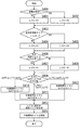
図4は、このときの画像形成装置1の動作や処理を示すフローチャートである。
画像形成装置1は、図示のように、まず、Bk画像書き込み同期信号108Bkをオンし(S100)、レジスト開始タイマR1を開始する(S101)。次に、作像間隔の計測結果(M1、M2)と、予め設定された作像間隔の基準値(基準作像間隔)C1とを比較し、計測した作像間隔がC1より長いか否かを判定する(S102)。その際、2枚目[A110]の作像間隔M1はC1よりも短いと判定され(S102、NO)、最大の生産性を達成するために通常設定されるタイマ値T1を給紙開始タイマに設定して、給紙開始タイマT1を開始し(S103)、Flag1をリセットする(S104)。このFlag1は、作像間隔が基準作像間隔C1よりも長いか否かを表すフラグであり、Flag1がリセットなら作像間隔がC1よりも短い通常の作像間隔、セットなら作像間隔がC1よりも長いことを表す。
FIG. 4 is a flowchart showing the operation and processing of the
As shown in the figure, the
これに対し、3枚目[A120]の作像間隔M2はC1よりも長いと判定され(S102、YES)、上記したタイマ値T1よりも小さいタイマ値T2(T2<T1)を給紙開始タイマに設定して、給紙開始タイマT2を開始する(S105)。このように、作像間隔の計測結果が通常の作像間隔よりも長いと判定されたときには、用紙Gの給紙を、通常時に設定された所定時間よりも早い時間に開始させ、通常の給紙開始よりも早いタイミングで用紙Gの給紙を開始する。また、Flag1をセットして(S106)、作像間隔がC1よりも長いことを記録する。続いて、これら給紙開始タイマT1、T2の終了に伴い、図3に示す[A112]、[A122]で、連続印刷の2枚目と3枚目の給紙を開始して印刷する。 On the other hand, it is determined that the image forming interval M2 of the third sheet [A120] is longer than C1 (S102, YES), and a timer value T2 (T2 <T1) smaller than the timer value T1 described above is set as a paper feed start timer. And the paper feed start timer T2 is started (S105). As described above, when it is determined that the measurement result of the image formation interval is longer than the normal image formation interval, the paper G is started to be fed at a time earlier than the predetermined time set in the normal time. The paper G starts to be fed at a timing earlier than the paper start. Also, Flag1 is set (S106), and it is recorded that the image forming interval is longer than C1. Subsequently, with the end of the paper feed start timers T1 and T2, the second and third continuous paper feeds are started and printed at [A112] and [A122] shown in FIG.
図5は、このときの画像形成装置1の動作や処理を示すフローチャートである。
画像形成装置1は、図示のように、給紙開始タイマ終了を確認し(S200)、給紙開始タイマが終了したら(S200、YES)、給紙クラッチ105をオンして用紙Gの給紙を開始する(S201)。続いて、Flag1の状態を確認し、Flag1がリセットなら(S202、NO)、不給紙ジャム検知タイマにタイマ値J1を設定して、タイマJ1を開始する(S203)。一方、Flag1がセットなら(S202、YES)、不給紙ジャム検知タイマにタイマ値J1よりも大きいタイマ値J2(J2>J1)を設定して、タイマJ2を開始する(S204)。このようにして、上記した給紙開始を早くしたのに合わせて(図4のS105、S106参照)、不給紙ジャム検知タイマを長くし、不給紙ジャムと判定される時間を長く設定し、不給紙ジャムの検知を遅らせている。
FIG. 5 is a flowchart showing the operation and processing of the
As shown in the figure, the
その後、画像形成装置1(図3参照)は、[A113]、[A123]でレジスト開始タイマR1が終了すると、上記した[A103]のときと同様に、レジストクラッチ106をオンして、レジストローラ3により、連続印刷2枚目と3枚目の用紙Gの給紙を再開する。続いて、各用紙Gに転写ベルト5の転写画像を順次転写等して、1枚目の用紙Gに続いて2、3枚目の用紙Gに連続して画像を印刷する。このように、画像形成装置1は、1以上(ここでは4つ)の色毎の画像を作像して転写画像を形成しつつ、その作像開始後の所定のタイミングで用紙Gを給紙し、これらを繰り返して、転写画像を順次形成して連続して給紙する用紙Gに転写して印刷する。
After that, when the registration start timer R1 ends at [A113] and [A123], the image forming apparatus 1 (see FIG. 3) turns on the registration clutch 106, as in [A103], and registers the registration roller. 3, the feeding of the second and third continuous paper G is resumed. Subsequently, the transfer image of the transfer belt 5 is sequentially transferred to each paper G, and the image is continuously printed on the second paper G following the first paper G. As described above, the
以上のように、この画像形成装置1は、作像手段の所定の基準となる色(基準色)(ここではBk)による画像の作像終了から、次の同色画像の作像開始までの作像間隔M1、M2を計測し、計測した作像間隔M1、M2と予め設定された基準作像間隔C1とを比較して、比較結果に基づいて給紙手段による次の用紙Gの給紙タイミングを変更する。ここでは、作像間隔同士の比較結果に基づき、計測した作像間隔M1、M2が基準作像間隔C1よりも長いか否かを判定し、計測した作像間隔が基準作像間隔C1よりも長い(M2)と判定されたときに、短い(M1)と判定されたときよりも早いタイミングで用紙Gの給紙を開始させる。また、作像間隔の比較結果に基づいて、上記した判定手段が給紙異常が発生したと判定する時間(不給紙ジャム検知タイマ)を変更し、計測した作像間隔が基準作像間隔C1よりも長いとき(M2)に、短いとき(M1)よりも長い時間(ここでは、J2)で給紙異常が発生したと判定させる。
As described above, the
従って、本実施形態の画像形成装置1は、これら各処理や動作を実行する計測手段、比較手段、判定手段、給紙タイミング変更手段、給紙異常時間変更手段等の各手段を備えている。これにより、画像形成装置1は、用紙Gの給紙開始のタイミングを、計測された作像間隔に応じて自動で、かつ必要なときに早めて、作像間隔が長くなる特定の場合に、用紙Gの給紙を通常よりも早く開始する。その結果、この画像形成装置1では、用紙Gの給紙が遅くなるのを防止でき、給紙搬送力のばらつきや給紙ローラ2の耐久劣化等にも対処可能で、不給紙ジャムと判定されるのを抑制して、その発生を低減することができる。これに伴い、適切な給紙処理を行うこともでき、印刷ミス等を防止して画像形成の品質を高めることもできる。また、この画像形成装置1では、用紙Gの給紙のタイミングを変更することで上記した各効果が得られるため、充分な印刷の効率を確保でき、不給紙ジャムの発生頻度を低減しつつ、印刷の生産性を向上させることができる。
Therefore, the
このように、本実施形態では、作像先行方式の画像形成装置1で給紙異常が発生する頻度を低減でき、画像形成の品質と生産性を向上させることができる。併せて、ここでは、計測した作像間隔が基準作像間隔C1よりも長いときに、短いときよりも長い時間で給紙異常(不給紙ジャム)と判定させるため、上記と同様に、作像間隔が長くなる特定の場合に、給紙異常と判定されるのを抑制することができる。その結果、給紙異常の発生頻度を確実に低減して、画像形成の品質と生産性を一層向上させることができる。
As described above, according to the present exemplary embodiment, it is possible to reduce the frequency of occurrence of paper feed abnormality in the
(第2の実施形態)
次に、本発明の第2の実施形態について説明する。
本実施形態の画像形成装置1Aは、第1の実施形態の画像形成装置1(図1、図2参照)に対して、その構成は基本的に同じであるが、異なる画像形成時の動作や処理が付加されている。以下、既に説明したのと異なる動作や処理について主に説明するが、ここでは、画像形成装置1Aに複数の給紙トレイが設けられ、それらをユーザの選択や指定等により切り替えて、印刷動作を実行する。
(Second Embodiment)
Next, a second embodiment of the present invention will be described.
The image forming apparatus 1A according to the present embodiment is basically the same in configuration as the
図6は、この画像形成装置1Aにより、カラー画像を連続して印刷するときのタイミングチャートである。
図示の例において、[A200]は、連続印刷1枚目の画像データ書き込み開始を示す。この画像形成装置1Aでも、Bk(ブラック)が用紙Gの給紙開始の基準となる給紙開始基準色であり、Bk画像書き込み同期信号108Bkがオンになると同時に、給紙開始タイマとレジスト開始タイマを開始する。また、他の画像書き込み同期信号108Y、108M、108Cや各画像の作像等の基本的な動作は、上記した第1の実施形態と同じであるが、ここでは、連続印刷1枚目の給紙開始タイマを、用紙Gの種類やサイズに応じて変更する。
FIG. 6 is a timing chart when color images are continuously printed by the image forming apparatus 1A.
In the illustrated example, [A200] indicates the start of writing image data for the first continuous print. In this image forming apparatus 1A as well, Bk (black) is the paper feed start reference color that is the reference for starting the paper G feed, and at the same time the Bk image write synchronization signal 108Bk is turned on, the paper feed start timer and the registration start timer To start. The basic operations such as the other image writing
図7は、このときの画像形成装置1Aの動作や処理を示すフローチャートである。
画像形成装置1Aは、図示のように、まず、ユーザから指示された用紙Gの種類(紙種)が所定の種類(ここでは、厚紙)か否かを判別する(S300)。その結果、紙種が厚紙以外(例えば普通紙)なら(S300、NO)、buff1に、最大生産性を達成するために通常設定される給紙開始タイマ値T1を格納する(S301)。一方、紙種が厚紙なら(S300、YES)、buff1に、T1よりも小さい給紙開始タイマ値T2(T2<T1)を格納する(S302)。これにより、特定の紙種(厚紙)の用紙Gを印刷するときには、通常の給紙開始よりも早いタイミングで用紙Gの給紙を開始させる。
FIG. 7 is a flowchart showing the operation and processing of the image forming apparatus 1A at this time.
As shown in the figure, the image forming apparatus 1A first determines whether or not the type (paper type) of the paper G instructed by the user is a predetermined type (here, thick paper) (S300). As a result, if the paper type is other than thick paper (for example, plain paper) (S300, NO), a paper feed start timer value T1 that is normally set to achieve maximum productivity is stored in buff1 (S301). On the other hand, if the paper type is thick paper (S300, YES), a paper feed start timer value T2 (T2 <T1) smaller than T1 is stored in buff1 (S302). Thus, when printing a paper G of a specific paper type (thick paper), the paper G is started to be fed at a timing earlier than the normal paper feed start.
次に、画像形成装置1Aは、ユーザから指示された用紙サイズの副走査方向の長さ(副走査用紙サイズ)が所定の用紙サイズ(ここでは、レター(279.6mm))未満かを判別する(S303)。その結果、レターよりも大きいときには(S303、NO)、buff2に、上記した給紙開始タイマ値T1を格納する(S304)。一方、レター未満なら(S303、YES)、buff2に、T1よりも小さい給紙開始タイマ値T3(T3<T1)を格納する(S305)。これにより、所定サイズよりも小さいサイズの用紙Gを印刷するときには、通常の給紙開始よりも早いタイミングで用紙Gの給紙を開始させる。ただし、このタイマ値T3と上記したT2は、T1よりも小さい値であればよく、T2とT3を同じ値に設定してもよい。 Next, the image forming apparatus 1A determines whether the length in the sub-scanning direction (sub-scanning paper size) of the paper size instructed by the user is less than a predetermined paper size (here, letter (279.6 mm)). (S303). If the result is larger than the letter (S303, NO), the paper feed start timer value T1 is stored in buff2 (S304). On the other hand, if it is less than the letter (S303, YES), a paper feed start timer value T3 (T3 <T1) smaller than T1 is stored in buff2 (S305). Thus, when printing a paper G having a size smaller than the predetermined size, the paper G is started to be fed at a timing earlier than the normal paper feed start. However, the timer value T3 and the above-described T2 need only be smaller than T1, and T2 and T3 may be set to the same value.
続いて、格納したbuff1とbuff2を比較して、それらの大小関係を判別する(S306)。その結果、buff1がbuff2以上(buff1≧buff2)であれば、給紙開始タイマにbuff1の値をセットし(S307)、buff1がbuff2未満(buff1<buff2)であれば、給紙開始タイマにbuff2の値をセットする(S308)。また、セットされた給紙開始タイマの値が、タイマ値T1と同じかを判別し(S309)、同じであれば(S309、YES)、上記と同様にFlag1をリセットし(S310)、異なれば(S309、NO)、Flag1をセットする(S311)。次に、現在の用紙Gを給紙する給紙トレイの情報をbuff5に格納し(S312)、セットした給紙開始タイマを開始して(S313)、上記と同様に1枚目の用紙Gへの印刷を行う。 Subsequently, the stored buff1 and buff2 are compared to determine their magnitude relationship (S306). As a result, if buff1 is equal to or greater than buff2 (buff1 ≧ buff2), the value of buff1 is set in the paper feed start timer (S307), and if buff1 is less than buff2 (buff1 <buff2), buff2 Is set (S308). Further, it is determined whether or not the set paper feed start timer value is the same as the timer value T1 (S309). If the timer value is the same (S309, YES), Flag1 is reset in the same manner as above (S310). (S309, NO), Flag1 is set (S311). Next, information on the paper feed tray that feeds the current paper G is stored in buff5 (S312), the set paper feed start timer is started (S313), and the first paper G is loaded in the same manner as described above. Print.
また、このように、給紙開始タイマを開始[A200](図6参照)した後、Bk画像書き込み同期信号108Bkを用紙長に応じた時間オンし、[A201]で、連続印刷1枚目のBk画像データの書き込みを終了して、Bk画像書き込み同期信号108Bkをオフする。ここでは、このオフに伴い、作像間隔タイマを開始し、その終了に合わせて、次のBk画像データの書き込みを開始[A210]する。同時に、Bk画像の作像間隔の計測を開始し、前ページのBk画像書き込み同期信号108Bkのオフ[A201]から次ページのBk画像書き込み同期信号108Bkのオン[A210]までの時間を計測する。 In this way, after the paper feed start timer is started [A200] (see FIG. 6), the Bk image writing synchronization signal 108Bk is turned on for a time corresponding to the paper length, and the first continuous print is performed in [A201]. The writing of the Bk image data is finished, and the Bk image writing synchronization signal 108Bk is turned off. Here, the image forming interval timer is started with this off, and writing of the next Bk image data is started [A210] in accordance with the end of the image forming interval timer. At the same time, measurement of the image forming interval of the Bk image is started, and the time from when the Bk image writing synchronization signal 108Bk of the previous page is turned off [A201] to when the Bk image writing synchronization signal 108Bk of the next page is turned on [A210] is measured.
図8は、この作像間隔タイマの設定手順を示すフローチャートである。
画像形成装置1Aは、図示のように、まず、ユーザから指示された用紙Gの紙種が厚紙か否かを判別する(S400)。その結果、紙種が厚紙以外(例えば普通紙)なら(S400、NO)、buff1に、最大生産性を達成するために通常設定される作像間隔タイマ値P1を格納する(S401)。一方、紙種が厚紙なら(S400、YES)、buff1に、P1よりも大きい作像間隔タイマ値P2(P2>P1)を格納する(S402)。このタイマ値P2には、上記した基準作像間隔C1よりも大きい値(P2>C1)が設定される。これにより、特定の紙種(厚紙)の用紙Gを連続して印刷するときに、Bk画像の作像間隔を、通常の連続印刷の作像間隔や基準作像間隔C1よりも長くし、第1の実施形態で説明した用紙Gの給紙を通常よりも早いタイミングで開始させる動作(図4参照)を実行させる。
FIG. 8 is a flowchart showing a procedure for setting the image forming interval timer.
As illustrated, the image forming apparatus 1A first determines whether the paper type of the paper G instructed by the user is a thick paper (S400). As a result, if the paper type is other than thick paper (for example, plain paper) (S400, NO), an image forming interval timer value P1 that is normally set to achieve maximum productivity is stored in buff1 (S401). On the other hand, if the paper type is thick paper (S400, YES), an image forming interval timer value P2 (P2> P1) larger than P1 is stored in buff1 (S402). The timer value P2 is set to a value (P2> C1) larger than the above-described reference image formation interval C1. As a result, when the paper G of a specific paper type (thick paper) is continuously printed, the image forming interval of the Bk image is set to be longer than the image forming interval of the normal continuous printing or the reference image forming interval C1. The operation (see FIG. 4) for starting the feeding of the paper G described in the first embodiment at a timing earlier than normal is performed.
次に、画像形成装置1Aは、ユーザから指示された用紙サイズの副走査方向の長さ(副走査用紙サイズ)がレター(279.6mm)未満かを判別する(S403)。その結果、レターよりも大きいときには(S403、NO)、buff2に、上記した通常設定される作像間隔タイマ値P1を格納する(S404)。一方、レター未満なら(S403、YES)、buff2に、P1よりも大きい作像間隔タイマ値P3(P3>P1)を格納する(S405)。このタイマ値P3には、タイマ値P2と同様に、基準作像間隔C1よりも大きい値(P3>C1)が設定される。これにより、所定サイズよりも小さいサイズの用紙Gを連続して印刷するときに、Bk画像の作像間隔を、通常の連続印刷の作像間隔や基準作像間隔C1よりも長くし、上記と同様に、用紙Gの給紙を通常よりも早いタイミングで開始させる動作を実行させる。 Next, the image forming apparatus 1A determines whether the length (sub-scanning paper size) of the paper size instructed by the user is less than the letter (279.6 mm) (S403). As a result, if it is larger than the letter (S403, NO), the above-mentioned normally set image forming interval timer value P1 is stored in buff2 (S404). On the other hand, if it is less than the letter (S403, YES), an image forming interval timer value P3 (P3> P1) larger than P1 is stored in buff2 (S405). The timer value P3 is set to a value (P3> C1) larger than the reference image forming interval C1, similarly to the timer value P2. As a result, when the paper G having a size smaller than the predetermined size is continuously printed, the image forming interval of the Bk image is set longer than the image forming interval of the normal continuous printing and the reference image forming interval C1. Similarly, an operation for starting the feeding of the paper G at a timing earlier than usual is executed.
続いて、画像形成装置1Aは、buff5に格納された情報から、前回の給紙トレイと、次に印刷する用紙Gを給紙する給紙トレイとを比較し、次の給紙トレイがbuff5の給紙トレイと同じか否かを判別して、その変更を確認する(S406)。その結果、給紙トレイが同じときには(S406、YES)、buff3に、作像間隔タイマ値P1を格納する(S407)。一方、給紙トレイが異なるときには(S406、NO)、buff3に、P1よりも大きい作像間隔タイマ値P4(P4>P1)を格納する(S408)。このタイマ値P4には、基準作像間隔C1よりも大きい値(P4>C1)が設定される。これにより、連続印刷中に給紙トレイが切り替わったときに、Bk画像の作像間隔を、通常の連続印刷の作像間隔や基準作像間隔C1よりも長くし、上記と同様に、用紙Gの給紙を通常よりも早いタイミングで開始させる動作を実行させる。 Subsequently, the image forming apparatus 1A compares the previous paper feed tray with the paper feed tray that feeds the paper G to be printed next from the information stored in the buff 5, and the next paper feed tray has the buff 5 as the next paper feed tray. It is determined whether or not it is the same as the paper feed tray, and the change is confirmed (S406). As a result, when the paper feed trays are the same (S406, YES), the image forming interval timer value P1 is stored in buff3 (S407). On the other hand, when the paper feed trays are different (S406, NO), an image forming interval timer value P4 (P4> P1) larger than P1 is stored in buff3 (S408). The timer value P4 is set to a value (P4> C1) larger than the reference image formation interval C1. As a result, when the paper feed tray is switched during continuous printing, the image forming interval of the Bk image is made longer than the image forming interval of the normal continuous printing and the reference image forming interval C1. The operation of starting the sheet feeding at a timing earlier than usual is executed.
また、画像形成装置1Aは、格納したbuff1、buff2、buff3を比較して、それらの大小関係を判別し(S409)、上記した各条件が複数重なり、複数の作像間隔タイマ値が格納されたときには、最も大きい作像間隔タイマを選択して、最も長く設定された作像間隔で作像する。即ち、(buff1≧buff2、buff3)であれば、作像間隔タイマにbuff1の値をセットし(S410)、(buff2>buff1、buff3)であれば、作像間隔タイマにbuff2の値をセットし(S411)、(buff3>buff1、buff2)であれば、作像間隔タイマにbuff3の値をセットする(S412)。次に、現在の用紙Gを給紙する給紙トレイの情報をbuff5に格納し(S413)、セットした作像間隔タイマを開始する(S414)。 In addition, the image forming apparatus 1A compares the stored buff1, buff2, and buff3 to determine the magnitude relationship between them (S409), and a plurality of the above-described conditions are overlapped to store a plurality of image forming interval timer values. Sometimes, the largest imaging interval timer is selected, and imaging is performed with the longest imaging interval. That is, if (buff1 ≧ buff2, buff3), the value of buff1 is set in the imaging interval timer (S410). If (buff2> buff1, buff3), the value of buff2 is set in the imaging interval timer. If (S411), (buff3> buff1, buff2), the value of buff3 is set in the image forming interval timer (S412). Next, information on the paper feed tray for feeding the current paper G is stored in buff 5 (S413), and the set image forming interval timer is started (S414).
その後、画像形成装置1Aは、開始した作像間隔タイマが終了すると、図6に示す[A210]と[A220]で、連続印刷2枚目と3枚目のBk画像データの書き込み(露光等)を開始する。ここでは、作像間隔タイマに、基準作像間隔C1よりも長いP2が設定されており、計測される作像間隔もC1よりも長いM2となる。そのため、給紙開始タイマには、通常時のT1よりも短いT2が設定され、用紙Gの給紙が、より早いタイミングで開始される。同様に、不給紙ジャム検知タイマには、通常時のJ1よりも長いJ2が設定される。その後の動作や処理は、第1の実施形態(図4参照)と同様であるため、説明は省略する。また、図6において、[A202]、[A212]、[A222]は、上記した給紙開始タイマT2の終了を示し、この給紙開始タイマの終了後の動作や処理は、第1の実施形態(図5参照)と同様である。[A203]、[A213]、[A223]は、上記したレジスト開始タイマR1の終了を示し、その終了に伴い、レジストクラッチ106をオンして、レジストローラ3により、連続印刷する各用紙Gの給紙を再開する。[A211]は、連続印刷2枚目のBk画像データの書き込み終了を示し、上記した[A201]での説明と同様に動作や処理が実行される。 Thereafter, when the started image forming interval timer ends, the image forming apparatus 1A writes Bk image data for the second and third continuous prints (exposure, etc.) in [A210] and [A220] shown in FIG. To start. Here, P2 longer than the reference image formation interval C1 is set in the image formation interval timer, and the measured image formation interval is M2, which is longer than C1. Therefore, T2 shorter than T1 in the normal time is set in the paper feed start timer, and the paper G starts to be fed at an earlier timing. Similarly, J2 longer than normal J1 is set in the non-paper jam detection timer. Subsequent operations and processing are the same as those in the first embodiment (see FIG. 4), and thus description thereof is omitted. In FIG. 6, [A202], [A212], and [A222] indicate the end of the paper feed start timer T2, and the operation and processing after the paper feed start timer ends are the same as those in the first embodiment. (See FIG. 5). [A203], [A213], and [A223] indicate the end of the above-described registration start timer R1, and at the end, the registration clutch 106 is turned on, and the registration roller 3 supplies the paper G for continuous printing. Resume paper. [A211] indicates the end of the writing of the Bk image data for the second continuous printing, and operations and processes are executed in the same manner as described in [A201].
以上説明した画像形成装置1Aでは、第1の実施形態で説明した各効果に加えて、紙種、用紙サイズ、給紙トレイ切り替えに応じて作像間隔を変更することで、用紙Gの給紙開始のタイミングを自動的に早めて、給紙異常(不給紙ジャム)の発生を効果的に低減することができる。即ち、この画像形成装置1は、上記したように、給紙される用紙Gの種類に応じて作像手段による所定色の画像(ここではBk画像)の作像間隔を変更し、所定種類の用紙Gのときに基準作像間隔C1よりも長い作像間隔で作像させる手段を備えている。これにより、例えば厚紙や光沢性の高い紙種等の給紙搬送力が落ちる用紙Gでは、用紙Gの給紙を通常よりも早く開始して給紙が遅くなるのを防止でき、不給紙ジャムと判定されるのを抑制して、用紙Gの種類に起因する給紙異常の発生頻度を低減することができる。併せて、このように、ユーザが使用する用紙Gの種類に応じて、より適切な給紙動作を実現できるため、給紙異常の低減に加えて、印刷ミス等を防止して画像形成の品質を高めることもできる。
In the image forming apparatus 1A described above, in addition to the effects described in the first embodiment, the image forming interval is changed in accordance with the paper type, paper size, and paper feed tray switching, thereby feeding the paper G. By automatically advancing the start timing, it is possible to effectively reduce the occurrence of paper feed abnormality (non-paper feed jam). That is, as described above, the
また、この画像形成装置1Aは、上記したように、給紙される用紙Gのサイズに応じて作像手段による所定色の画像(ここではBk画像)の作像間隔を変更し、所定サイズよりも小さいサイズの用紙Gのときに基準作像間隔C1よりも長い作像間隔で作像させる手段を備えている。これにより、給紙搬送力の落ちる小サイズの用紙Gを使用するときに、用紙Gの給紙を通常よりも早く開始して給紙が遅くなるのを防止でき、併せて、ユーザが使用する用紙Gのサイズに応じて、より適切な給紙動作を実現できる。その結果、用紙Gのサイズに起因する給紙異常の発生頻度を低減できるとともに、画像形成の品質を高めることもできる。 Further, as described above, the image forming apparatus 1A changes the image forming interval of an image of a predetermined color (here, a Bk image) by the image forming unit in accordance with the size of the paper G to be fed. Means for forming an image with an image forming interval longer than the reference image forming interval C1 when the paper G is smaller in size. As a result, when using a small-sized paper G having a low paper feeding / conveying power, it is possible to prevent the paper G from being fed earlier than usual and to prevent the paper feeding from being delayed, and also used by the user. Depending on the size of the paper G, a more appropriate paper feeding operation can be realized. As a result, it is possible to reduce the occurrence frequency of sheet feeding abnormalities due to the size of the sheet G and to improve the quality of image formation.
更に、この画像形成装置1Aは、上記したように、給紙手段の用紙Gを給紙する給紙トレイが切り替わったときに、作像手段による所定色の画像(ここではBk画像)の作像間隔を変更し、基準作像間隔C1よりも長い作像間隔で作像させる手段を備えている。これにより、連続印刷中に給紙トレイを切り替えた際に、例えば給紙トレイの用紙連れ送り量の違い等があっても、用紙Gの給紙を通常よりも早く開始して給紙が遅くなるのを防止することができる。また、給紙トレイ毎の給紙品質のばらつきによらず、適切な給紙動作を実現できるため、給紙異常の発生頻度を低減しつつ、画像形成の品質を高めることもできる。 Further, as described above, the image forming apparatus 1A forms an image of a predetermined color (here, a Bk image) by the image forming unit when the paper feed tray that feeds the paper G of the paper feed unit is switched. Means are provided for changing the interval and forming an image with an image forming interval longer than the reference image forming interval C1. As a result, when the paper feed tray is switched during continuous printing, for example, even if there is a difference in the paper feed amount of the paper feed tray, the paper G feeding is started earlier than usual and the paper feeding is delayed. Can be prevented. In addition, an appropriate sheet feeding operation can be realized regardless of variations in sheet feeding quality for each sheet feeding tray, so that it is possible to improve the quality of image formation while reducing the frequency of occurrence of sheet feeding abnormality.
更にまた、この画像形成装置1Aは、上記したように、用紙Gの種類、サイズ、給紙トレイの切り替えに応じて作像間隔を変更する各手段に加えて、基準作像間隔C1よりも長い作像間隔が複数設定されたとき、最も長い作像間隔で作像手段によりBk画像を作像させる手段を備えている。従って、作像間隔を長くする条件が重なった場合でも、最適な作像間隔を選択して適切な給紙動作を実現でき、給紙異常の発生頻度を低減しつつ、画像形成の品質を一層高めることもできる。 Furthermore, as described above, the image forming apparatus 1A is longer than the reference image forming interval C1 in addition to each means for changing the image forming interval in accordance with the type and size of the paper G and the switching of the paper feed tray. When a plurality of image forming intervals are set, there is provided means for forming a Bk image by the image forming means at the longest image forming interval. Therefore, even when the conditions for increasing the image forming interval overlap, it is possible to select the optimum image forming interval and realize an appropriate paper feeding operation, and to further improve the image forming quality while reducing the frequency of occurrence of paper feeding abnormalities. It can also be increased.
(第3の実施形態)
次に、本発明の第3の実施形態について説明する。
本実施形態の画像形成装置1Bは、第1と第2の実施形態に対して構成は基本的に同じであり、連続印刷中に不給紙ジャムが発生したときの動作や処理が付加されている。以下、第1と第2の実施形態と異なる動作や処理について主に説明し、既に説明した連続印刷中の作像間隔や給紙動作等についての説明は省略する。
(Third embodiment)
Next, a third embodiment of the present invention will be described.
The image forming apparatus 1B of the present embodiment is basically the same in configuration as the first and second embodiments, and is added with operations and processing when a non-paper jam occurs during continuous printing. Yes. In the following, operations and processes different from those in the first and second embodiments will be mainly described, and description of the image forming interval and paper feeding operation during the continuous printing already described will be omitted.
図9は、この画像形成装置1Bにより、カラー画像を連続して印刷するときのタイミングチャートである。
図示の例において、[A314]は、連続印刷2枚目の給紙実行時に不給紙ジャムが発生して、上記した給紙異常の判定手段が給紙異常と判定したときである。画像形成装置1Bは、[A314]で不給紙ジャムが発生すると同時に、不給紙ジャム情報120を[A315]でオンし、このオンの情報と不給紙ジャムが発生した給紙トレイに対応する情報を、給紙異常情報としてNVRAM104(図2参照)に記憶する。これにより、不給紙ジャム発生後に本体電源をユーザがオフにしても、電源オフ前の各情報を残すことができる。
FIG. 9 is a timing chart when color images are continuously printed by the image forming apparatus 1B.
In the example shown in the drawing, [A314] is when a non-feed jam occurs when the second continuous printing is performed, and the above-described paper feed abnormality determination unit determines that the paper feed is abnormal. The image forming apparatus 1B turns on the non-paper jam information 120 with [A315] at the same time when a non-paper jam occurs in [A314], and corresponds to the on-information and the paper feed tray in which the non-paper jam occurs. The information to be stored is stored in the NVRAM 104 (see FIG. 2) as paper feed abnormality information. Thereby, even if the user turns off the main body power after the occurrence of a non-paper jam, it is possible to leave each information before the power is turned off.
[A330]以降は、ユーザが[A314]で発生した不給紙ジャムを解除した後に、不給紙ジャムが発生したのと同じ給紙トレイから連続印刷を実行したときの動作や処理を示している。画像形成装置1Bは、不給紙ジャムが解除されても不給紙ジャム情報120をオンに維持し、このオンの間は、以降の連続印刷でも不給紙ジャムが発生する可能性があると判断する。従って、この連続印刷中は、第2の実施形態で説明した作像間隔タイマに、基準作像間隔C1よりも長いタイマ値P2を設定し、通常の連続印刷の作像間隔P1よりも長い作像間隔P2で作像させる。これにより、以降の印刷で、NVRAM104に記憶した給紙異常情報の、不給紙ジャム情報120に対応する給紙トレイから連続印刷を行うときに、第1と第2の実施形態で説明した用紙Gの給紙を通常よりも早いタイミングで開始させる動作を実行させる。
[A330] and subsequent figures show operations and processes when continuous printing is executed from the same paper feed tray as that in which the non-paper jam occurred after the user canceled the non-paper jam that occurred in [A314]. Yes. The image forming apparatus 1B maintains the non-paper jam information 120 on even when the non-paper jam is canceled. During this on, the non-paper jam may occur even in subsequent continuous printing. to decide. Accordingly, during this continuous printing, the timer value P2 longer than the reference image formation interval C1 is set in the image formation interval timer described in the second embodiment, and the image formation interval P1 longer than the normal image formation interval P1 is set. An image is formed at an image interval P2. Thus, in the subsequent printing, when continuous printing is performed from the paper feed tray corresponding to the non-paper jam information 120 of the paper feed abnormality information stored in the
また、この不給紙ジャム情報120は、同じ給紙トレイから用紙Gを順次給紙して、連続印刷の最終の用紙Gの給紙が行われた時点[A355]でオフにし、同時に、このオフの情報をNVRAM104に記憶して、以前のオン情報や給紙トレイの情報を消去する。このように、画像形成装置1Bは、NVRAM104に記憶された給紙トレイに対応したジャム発生情報を、作像間隔を長くした連続印刷が不給紙ジャムを発生することなく正常に終了したときにリセットする。
Further, the non-paper jam information 120 is turned off at the time [A355] when the paper G is sequentially fed from the same paper feed tray and the final paper G is continuously fed. The off information is stored in the
以上のように、本実施形態の画像形成装置1Bは、上記した判定手段により給紙異常と判定されたとき、給紙異常が発生した給紙トレイを記憶する手段と、記憶された給紙トレイから続けて用紙が給紙されるとき、作像手段により、所定色の画像(ここではBk画像)を基準作像間隔C1よりも長い作像間隔で作像させる手段を備えている。これにより、不給紙ジャムが一旦発生した給紙トレイから用紙Gを続けて給紙するときに、用紙Gの給紙を通常よりも早く開始して、不給紙ジャムが再発し難いよう給紙のための時間を長くでき、適切な給紙動作を実現することができる。その結果、例えば給紙ローラ2の耐久劣化によって不給紙ジャムが発生し易い状況等においても、不給紙ジャムの発生を抑制でき、給紙異常の発生頻度を低減しつつ、画像形成の品質を高めることもできる。
As described above, the image forming apparatus 1B according to the present embodiment includes a unit that stores a paper feed tray in which a paper feed abnormality has occurred and a stored paper feed tray when the paper feeding abnormality is determined by the determination unit. When the sheet is continuously fed, the image forming means includes means for forming an image of a predetermined color (here, Bk image) at an image forming interval longer than the reference image forming interval C1. As a result, when the paper G is continuously fed from the paper feed tray once the non-feed jam has occurred, the paper G is started to be fed earlier than usual so that the non-feed jam is unlikely to recur. The time for paper can be lengthened and an appropriate paper feeding operation can be realized. As a result, for example, even in a situation where non-feed jam is likely to occur due to deterioration of durability of the
加えて、この画像形成装置1Bは、上記したように、給紙異常が発生せずに、記憶された給紙トレイからの続けての用紙Gの給紙が終了したとき、給紙トレイを記憶する手段(ここではNVRAM104)の記憶をリセットする手段を備えている。これにより、連続した印刷で不給紙ジャムが発生しないときには、それ以降の印刷で、作像間隔や給紙時間を通常のタイミングに自動で戻すことができ、画像形成の生産性を損なわずに高く維持することができる。 In addition, as described above, the image forming apparatus 1B stores the paper feed tray when the continuous feeding of the paper G from the stored paper feed tray is completed without causing a paper feed abnormality. Means for resetting the memory (in this case, NVRAM 104). As a result, when no paper jam occurs in continuous printing, the image forming interval and paper feeding time can be automatically returned to normal timing in subsequent printing, without impairing image formation productivity. Can be kept high.
1・・・画像形成装置、2・・・給紙ローラ、3・・・レジストローラ、4・・・給紙トレイ、5・・・転写ベルト、6Bk、6Y、6M、6C・・・カートリッジ、7・・・二次転写駆動ローラ、8・・・転写ベルトテンションローラ、9Bk、9Y、9M、9C・・・感光体、10Bk、10Y、10M、10C・・・帯電器、11・・・露光器、12Bk、12Y、12M、12C・・・現像器、13Bk、13Y、13M、13C・・・クリーナーブレード、14Bk、14Y、14M、14C・・・レーザ光、15Bk、15Y、15M、15C・・・一次転写ローラ、16・・・二次転写ローラ、18・・・排紙ローラ、19・・・両面ローラ、30・・・定着器、101・・・CPU、102・・・FlashROM、103・・・SRAM、104・・・NVRAM、105・・・給紙クラッチ、106・・・レジストクラッチ、107・・・レジストセンサ、108・・・画像書き込み同期信号、109・・・コントローラ、110・・・PSU、111・・・HVP、H・・・搬送経路、G・・・用紙。
DESCRIPTION OF
Claims (9)
作像手段の所定色による画像の作像終了から次の作像開始までの作像間隔を計測する手段と、
計測した作像間隔と予め設定された基準作像間隔とを比較する手段と、
作像間隔の比較結果に基づいて給紙手段による用紙の給紙タイミングを変更し、計測した作像間隔が基準作像間隔よりも長いときに短いときよりも早いタイミングで給紙を開始させる手段と、
を備えたことを特徴とする画像形成装置。 An image forming unit that forms an image for each of one or more colors to form a transfer image; and a paper feeding unit that feeds a sheet at a predetermined timing after the start of image formation by the image forming unit. An image forming apparatus that sequentially forms and transfers to continuously fed paper,
Means for measuring an image forming interval from the end of image formation by a predetermined color of the image forming means to the start of the next image formation;
Means for comparing the measured image forming interval with a preset reference image forming interval;
Means for changing the paper feeding timing by the paper feeding means based on the comparison result of the image forming intervals, and starting the paper feeding at a timing earlier than when the measured image forming interval is longer than the reference image forming interval. When,
An image forming apparatus comprising:
給紙手段から給紙された用紙を転写画像の転写前に検知する検知センサと、
用紙の給紙開始から所定時間内に検知センサが用紙を検知しないときに給紙異常と判定する判定手段と、
作像間隔の比較結果に基づいて判定手段が給紙異常と判定する時間を変更し、計測した作像間隔が基準作像間隔よりも長いときに短いときよりも長い時間で給紙異常と判定させる手段と、
を備えたことを特徴とする画像形成装置。 The image forming apparatus according to claim 1,
A detection sensor for detecting the paper fed from the paper feeding means before transferring the transfer image;
Determining means for determining that the paper feeding is abnormal when the detection sensor does not detect paper within a predetermined time from the start of paper feeding;
Based on the comparison result of the image forming interval, the determination unit changes the time for determining that the paper feeding is abnormal, and when the measured image forming interval is longer than the reference image forming interval, it is determined that the paper feeding is abnormal in a longer time than when it is short. Means to
An image forming apparatus comprising:
用紙の種類に応じて作像手段による前記所定色の画像の作像間隔を変更し、所定種類の用紙のときに基準作像間隔よりも長い作像間隔で作像させる手段を備えたことを特徴とする画像形成装置。 The image forming apparatus according to claim 1 or 2,
According to the present invention, there is provided means for changing the image forming interval of the image of the predetermined color by the image forming unit in accordance with the type of paper, and forming an image with an image forming interval longer than the reference image forming interval when the paper is of a predetermined type. An image forming apparatus.
用紙のサイズに応じて作像手段による前記所定色の画像の作像間隔を変更し、所定サイズよりも小さいサイズの用紙のときに基準作像間隔よりも長い作像間隔で作像させる手段を備えたことを特徴とする画像形成装置。 The image forming apparatus according to claim 1 or 2,
Means for changing the image forming interval of the image of the predetermined color by the image forming means according to the size of the paper, and forming an image with an image forming interval longer than the reference image forming interval when the paper is smaller than the predetermined size; An image forming apparatus comprising the image forming apparatus.
給紙手段が、それぞれ用紙を給紙可能な複数の給紙トレイを有し、
給紙手段の用紙を給紙する給紙トレイが切り替わったときに、作像手段による前記所定色の画像の作像間隔を変更し、基準作像間隔よりも長い作像間隔で作像させる手段を備えたことを特徴とする画像形成装置。 The image forming apparatus according to claim 1 or 2,
The paper feed means has a plurality of paper feed trays each capable of feeding paper,
Means for changing the image forming interval of the image of the predetermined color by the image forming means and forming an image with an image forming interval longer than the reference image forming interval when the paper supply tray for feeding the paper of the paper supplying means is switched. An image forming apparatus comprising:
給紙手段が、用紙を給紙可能な少なくとも1つの給紙トレイを有し、
用紙の種類に応じて作像手段による前記所定色の画像の作像間隔を変更し、所定種類の用紙のときに基準作像間隔よりも長い作像間隔で作像させる手段と、
用紙のサイズに応じて作像手段による前記所定色の画像の作像間隔を変更し、所定サイズよりも小さいサイズの用紙のときに基準作像間隔よりも長い作像間隔で作像させる手段と、
給紙手段の用紙を給紙する給紙トレイが切り替わったときに、作像手段による前記所定色の画像の作像間隔を変更し、基準作像間隔よりも長い作像間隔で作像させる手段と、
作像手段の作像間隔を変更する際、基準作像間隔よりも長い作像間隔が複数設定されたとき、最も長い作像間隔で作像手段により作像させる手段と、
を備えたことを特徴とする画像形成装置。 The image forming apparatus according to claim 1 or 2,
The paper feed means has at least one paper feed tray capable of feeding paper,
Means for changing the image forming interval of the image of the predetermined color by the image forming means according to the type of paper, and forming an image at an image forming interval longer than the reference image forming interval when the paper is of a predetermined type;
Means for changing the image forming interval of the image of the predetermined color by the image forming means in accordance with the size of the paper, and forming an image at an image forming interval longer than the reference image forming interval when the paper is smaller than the predetermined size; ,
Means for changing the image forming interval of the image of the predetermined color by the image forming means and forming an image with an image forming interval longer than the reference image forming interval when the paper supply tray for feeding the paper of the paper supplying means is switched. When,
When changing the image forming interval of the image forming means, when a plurality of image forming intervals longer than the reference image forming interval are set, means for causing the image forming means to form an image at the longest image forming interval;
An image forming apparatus comprising:
給紙手段が、用紙を給紙可能な少なくとも1つの給紙トレイを有し、
判定手段により給紙異常と判定されたとき、給紙異常が発生した給紙トレイを記憶する手段と、
記憶された給紙トレイから続けて用紙が給紙されるとき、作像手段により、前記所定色の画像を基準作像間隔よりも長い作像間隔で作像させる手段と、
を備えたことを特徴とする画像形成装置。 The image forming apparatus according to claim 2,
The paper feed means has at least one paper feed tray capable of feeding paper,
Means for storing a paper feed tray in which a paper feed abnormality has occurred when the judgment means determines that the paper feed is abnormal;
Means for causing the image forming means to form an image of the predetermined color at an image forming interval longer than a reference image forming interval when paper is continuously fed from the stored paper feed tray;
An image forming apparatus comprising:
給紙異常が発生せずに、記憶された給紙トレイからの続けての用紙の給紙が終了したとき、給紙トレイを記憶する手段の記憶をリセットする手段を備えたことを特徴とする画像形成装置。 The image forming apparatus according to claim 7,
A means for resetting the memory of the means for storing the paper feed tray is provided when the paper feed from the stored paper feed tray is completed without causing a paper feed error. Image forming apparatus.
作像工程の所定色による画像の作像終了から次の作像開始までの作像間隔を計測する工程と、
計測した作像間隔と予め設定された基準作像間隔とを比較する工程と、
作像間隔の比較結果に基づいて給紙工程による用紙の給紙タイミングを変更し、計測した作像間隔が基準作像間隔よりも長いときに短いときよりも早いタイミングで給紙を開始させる工程と、
を有することを特徴とする画像形成方法。 An image forming process for forming an image for each of one or more colors to form a transfer image, and a paper feeding process for feeding paper at a predetermined timing after the start of image formation in the image forming process. An image forming method of an image forming apparatus for sequentially forming images and transferring them to a sheet to be continuously fed,
A step of measuring an image formation interval from the end of image formation by a predetermined color in the image formation step to the start of the next image formation;
Comparing the measured imaging interval with a preset reference imaging interval;
A step of changing the paper feeding timing in the paper feeding process based on the comparison result of the image forming intervals, and starting the paper feeding at a timing earlier than when the measured image forming interval is longer than the reference image forming interval. When,
An image forming method comprising:
Priority Applications (1)
| Application Number | Priority Date | Filing Date | Title |
|---|---|---|---|
| JP2009059475A JP5440899B2 (en) | 2009-03-12 | 2009-03-12 | Image forming apparatus and image forming method |
Applications Claiming Priority (1)
| Application Number | Priority Date | Filing Date | Title |
|---|---|---|---|
| JP2009059475A JP5440899B2 (en) | 2009-03-12 | 2009-03-12 | Image forming apparatus and image forming method |
Publications (2)
| Publication Number | Publication Date |
|---|---|
| JP2010211119A true JP2010211119A (en) | 2010-09-24 |
| JP5440899B2 JP5440899B2 (en) | 2014-03-12 |
Family
ID=42971323
Family Applications (1)
| Application Number | Title | Priority Date | Filing Date |
|---|---|---|---|
| JP2009059475A Expired - Fee Related JP5440899B2 (en) | 2009-03-12 | 2009-03-12 | Image forming apparatus and image forming method |
Country Status (1)
| Country | Link |
|---|---|
| JP (1) | JP5440899B2 (en) |
Cited By (7)
| Publication number | Priority date | Publication date | Assignee | Title |
|---|---|---|---|---|
| JP2013095549A (en) * | 2011-10-31 | 2013-05-20 | Kyocera Document Solutions Inc | Image forming apparatus |
| JP2013225012A (en) * | 2012-04-20 | 2013-10-31 | Ricoh Co Ltd | Image formation control device, image forming apparatus, and control method of image forming apparatus |
| US8724190B2 (en) | 2011-05-09 | 2014-05-13 | Ricoh Company, Limited | Image forming apparatus, image forming method, and computer-readable recording medium |
| JP2015218006A (en) * | 2014-05-14 | 2015-12-07 | 京セラドキュメントソリューションズ株式会社 | Sheet supply device, image formation device, control method for sheet supply device |
| JP2017197331A (en) * | 2016-04-27 | 2017-11-02 | 京セラドキュメントソリューションズ株式会社 | Image forming device |
| US10324410B2 (en) | 2016-04-27 | 2019-06-18 | Kyocera Document Solutions Inc. | Image forming apparatus |
| JP2021011342A (en) * | 2019-07-05 | 2021-02-04 | コニカミノルタ株式会社 | Paper feeding device, image forming device and paper feeding method |
Citations (4)
| Publication number | Priority date | Publication date | Assignee | Title |
|---|---|---|---|---|
| JP2000233839A (en) * | 1999-02-15 | 2000-08-29 | Canon Inc | Image forming device and its control method |
| JP2004272065A (en) * | 2003-03-11 | 2004-09-30 | Canon Inc | Image forming apparatus |
| JP2008127116A (en) * | 2006-11-16 | 2008-06-05 | Ricoh Co Ltd | Image forming device |
| JP2008225157A (en) * | 2007-03-14 | 2008-09-25 | Canon Inc | Image forming device |
-
2009
- 2009-03-12 JP JP2009059475A patent/JP5440899B2/en not_active Expired - Fee Related
Patent Citations (4)
| Publication number | Priority date | Publication date | Assignee | Title |
|---|---|---|---|---|
| JP2000233839A (en) * | 1999-02-15 | 2000-08-29 | Canon Inc | Image forming device and its control method |
| JP2004272065A (en) * | 2003-03-11 | 2004-09-30 | Canon Inc | Image forming apparatus |
| JP2008127116A (en) * | 2006-11-16 | 2008-06-05 | Ricoh Co Ltd | Image forming device |
| JP2008225157A (en) * | 2007-03-14 | 2008-09-25 | Canon Inc | Image forming device |
Cited By (7)
| Publication number | Priority date | Publication date | Assignee | Title |
|---|---|---|---|---|
| US8724190B2 (en) | 2011-05-09 | 2014-05-13 | Ricoh Company, Limited | Image forming apparatus, image forming method, and computer-readable recording medium |
| JP2013095549A (en) * | 2011-10-31 | 2013-05-20 | Kyocera Document Solutions Inc | Image forming apparatus |
| JP2013225012A (en) * | 2012-04-20 | 2013-10-31 | Ricoh Co Ltd | Image formation control device, image forming apparatus, and control method of image forming apparatus |
| JP2015218006A (en) * | 2014-05-14 | 2015-12-07 | 京セラドキュメントソリューションズ株式会社 | Sheet supply device, image formation device, control method for sheet supply device |
| JP2017197331A (en) * | 2016-04-27 | 2017-11-02 | 京セラドキュメントソリューションズ株式会社 | Image forming device |
| US10324410B2 (en) | 2016-04-27 | 2019-06-18 | Kyocera Document Solutions Inc. | Image forming apparatus |
| JP2021011342A (en) * | 2019-07-05 | 2021-02-04 | コニカミノルタ株式会社 | Paper feeding device, image forming device and paper feeding method |
Also Published As
| Publication number | Publication date |
|---|---|
| JP5440899B2 (en) | 2014-03-12 |
Similar Documents
| Publication | Publication Date | Title |
|---|---|---|
| JP5440899B2 (en) | Image forming apparatus and image forming method | |
| JP2009025814A (en) | Image forming apparatus | |
| US20080048392A1 (en) | Image forming apparatus, sheet-conveyance control method, and sheet-conveyance control program | |
| JP2007183352A (en) | Image forming apparatus, image forming method and imaging forming program | |
| US9274475B2 (en) | Image forming apparatus, image forming system, and image forming method | |
| JP2004021101A (en) | Apparatus and method for image formation | |
| JP2017068191A (en) | Image forming apparatus | |
| JP2016071289A (en) | Image forming apparatus | |
| US20110262163A1 (en) | Image transfer position adjustment | |
| JP5049471B2 (en) | Image forming apparatus | |
| JP2005202110A (en) | Image forming apparatus | |
| JP5434172B2 (en) | Image forming apparatus and image forming method | |
| JP4232324B2 (en) | Image forming apparatus | |
| JP2012133340A (en) | Image forming device capable of controlling printing interruption, control method thereof, and storage medium | |
| JP2006330460A (en) | Image forming apparatus | |
| JP2014222294A (en) | Image forming apparatus | |
| JP2011191504A (en) | Image forming apparatus | |
| JP2016139117A (en) | Image forming apparatus | |
| JP2009053307A (en) | Image forming apparatus | |
| JP2006195180A (en) | Image forming apparatus and its control method | |
| JP2006130779A (en) | Image forming apparatus | |
| JP2005015166A (en) | Image forming device and controlling method thereof | |
| JP2013225012A (en) | Image formation control device, image forming apparatus, and control method of image forming apparatus | |
| JP5305869B2 (en) | Image forming apparatus | |
| JP7215279B2 (en) | image forming device |
Legal Events
| Date | Code | Title | Description |
|---|---|---|---|
| A621 | Written request for application examination |
Free format text: JAPANESE INTERMEDIATE CODE: A621 Effective date: 20120130 |
|
| A521 | Written amendment |
Free format text: JAPANESE INTERMEDIATE CODE: A523 Effective date: 20120620 |
|
| A131 | Notification of reasons for refusal |
Free format text: JAPANESE INTERMEDIATE CODE: A131 Effective date: 20130225 |
|
| A977 | Report on retrieval |
Free format text: JAPANESE INTERMEDIATE CODE: A971007 Effective date: 20130227 |
|
| A521 | Written amendment |
Free format text: JAPANESE INTERMEDIATE CODE: A523 Effective date: 20130416 |
|
| TRDD | Decision of grant or rejection written | ||
| A01 | Written decision to grant a patent or to grant a registration (utility model) |
Free format text: JAPANESE INTERMEDIATE CODE: A01 Effective date: 20131122 |
|
| A61 | First payment of annual fees (during grant procedure) |
Free format text: JAPANESE INTERMEDIATE CODE: A61 Effective date: 20131205 |
|
| LAPS | Cancellation because of no payment of annual fees |