JP2010209621A - Floor slab bridge and method for constructing the same - Google Patents
Floor slab bridge and method for constructing the same Download PDFInfo
- Publication number
- JP2010209621A JP2010209621A JP2009058742A JP2009058742A JP2010209621A JP 2010209621 A JP2010209621 A JP 2010209621A JP 2009058742 A JP2009058742 A JP 2009058742A JP 2009058742 A JP2009058742 A JP 2009058742A JP 2010209621 A JP2010209621 A JP 2010209621A
- Authority
- JP
- Japan
- Prior art keywords
- square steel
- rod
- steel pipe
- opening
- shaped member
- Prior art date
- Legal status (The legal status is an assumption and is not a legal conclusion. Google has not performed a legal analysis and makes no representation as to the accuracy of the status listed.)
- Granted
Links
Images


Abstract
Description
本発明は、土木建築分野における橋梁に関し、特に角形鋼管を用いた床版橋およびその構築方法に関する。 The present invention relates to a bridge in the field of civil engineering and architecture, and more particularly to a floor slab bridge using a square steel pipe and a construction method thereof.
従来、角形鋼管あるいは形鋼を並列して配置して一体化した床版橋あるいは覆工板としては、次の(1)〜(5)のような技術が知られている。
(1)橋軸方向に伸長する角形鋼管を橋軸直角方向に複数本並行に配設し、前記角形鋼管の側面に開口部を設け、該開口部に鋼管、棒鋼、鉄筋などの棒状部材を挿通し、角形鋼管内で棒状部材を挟んでその両側に仕切り板を設け、この仕切り板で区画される内側にコンクリートなどの経時硬化性材料を充填することで、橋軸直角方向にせん断キーを構成し、前記角形鋼管相互を締結して床版を構成した床版橋が知られている(例えば、特許文献1参照)。
Conventionally, techniques such as the following (1) to (5) are known as floor slab bridges or lining plates in which square steel pipes or shaped steels are arranged in parallel and integrated.
(1) A plurality of rectangular steel pipes extending in the direction of the bridge axis are arranged in parallel in the direction perpendicular to the bridge axis, an opening is provided on the side of the square steel pipe, and a bar-shaped member such as a steel pipe, steel bar, or reinforcing bar is provided in the opening. Insert a partition plate on both sides of the rod-shaped member in the square steel pipe, and fill the inner side of the partition plate with a time-hardening material such as concrete so that a shear key is applied in the direction perpendicular to the bridge axis. There is known a floor slab bridge that is constructed and configured by fastening the square steel pipes together to form a floor slab (for example, see Patent Document 1).
(2)角形鋼管を複数本敷き並べて路面を構成する床版橋の製造において、複数本敷き並べた角形鋼管の側面に垂直な方向から荷重をかけ、表面にズレ止めを有する棒状部材を角形鋼管の側面から挿入し、棒状部材の周囲を含む角形鋼管内部にコンクリートなどの経時硬化性材料を打設し、経時硬化性材料が硬化した後に荷重を解放してプレストレスを導入する角形鋼管を用いた床版橋の製造方法も知られている(例えば、特許文献2参照)。 (2) In the manufacture of floor slab bridges, in which a plurality of rectangular steel pipes are laid out to form a road surface, a rod-shaped member having a displacement stop on the surface is applied with a load applied in a direction perpendicular to the side surfaces of the square steel pipes laid out in a plurality of lines. Use a square steel pipe that is inserted from the side of the tube and casts time-hardening material such as concrete inside the square steel pipe including the periphery of the rod-shaped member and releases preload after the time-hardening material is hardened. A method for manufacturing a conventional slab bridge is also known (see, for example, Patent Document 2).
(3)角形鋼管を複数本敷き並べ、コンクリートなどの経時硬化性材料を打設して前記角形鋼管を一体化させた覆工板であって、更に、前記覆工板本体の上面に施設される滑り止め部材と、前記経時硬化性材料に固定されて前記角形鋼管の上面の開口部に配置された定着金具とを有し、前記滑り止め部材が前記定着金具に固定されている角形鋼管を用いた覆工板も知られている(例えば、特許文献3参照)。 (3) A lining plate in which a plurality of rectangular steel pipes are laid out and a time-hardening material such as concrete is placed to integrate the rectangular steel pipes, and further provided on the upper surface of the lining plate main body. An anti-slip member, and a fixing metal fitting fixed to the time-hardening material and disposed in an opening on the upper surface of the square steel pipe, and the anti-slip member is fixed to the fixing metal fitting. The lining board used is also known (see, for example, Patent Document 3).
(4)角形鋼管を主桁として使用し、隣り合う角形鋼管を、横桁を介して互いに連結するとともに、鋼床版を補強するための縦リブを横桁により支持し、隣接する各部材を高力ボルトによりそれぞれ互いに接合して一体構造にする、角形鋼管を主桁に用いた橋梁構造も知られている(例えば、特許文献4参照)。 (4) A rectangular steel pipe is used as a main girder, adjacent square steel pipes are connected to each other via a horizontal girder, and vertical ribs for reinforcing a steel deck are supported by a horizontal girder, and adjacent members are A bridge structure using a square steel pipe as a main girder that is joined to each other with high-strength bolts to form an integral structure is also known (for example, see Patent Document 4).
(5)なお、H形鋼のフランジ同士を溶接により接合して一体化し、さらに、端部の補強、泥などの堆積を防ぐため、側面、端面に鋼板を溶接してなる覆工板も知られている。 (5) In addition, H-shaped steel flanges are joined and integrated by welding, and a lining plate made by welding steel plates to the side and end faces is also known in order to reinforce end portions and prevent mud accumulation. It has been.
前記従来の場合は、並行して配置された角形鋼管をこれらにわたって挿通配置された棒状部材および隣り合う角形鋼管内に渡って充填されると共に前記棒状部材を埋め込むコンクリート等の固化材により一体化するので、分解して撤去することが困難なものであるため、仮設用の橋梁としては適していなかった。また、コンクリートの充填作業等、現場作
業が煩雑であった。また、並行して配置されたH形鋼のフランジ相互を溶接により一体化する覆工板の場合には、溶接作業が必要になるという問題があった。
本発明は、本設用としても、仮設用としても利用可能で、コンクリートの充填作業あるいは現場での溶接作業の必要のない床版橋およびその構築方法を提供することを目的とする。
In the conventional case, the rectangular steel pipes arranged in parallel are filled with the bar-like member inserted through them and the adjacent square steel pipes, and are integrated by a solidifying material such as concrete that embeds the rod-like member. Therefore, since it is difficult to disassemble and remove, it was not suitable as a temporary bridge. Also, field work such as concrete filling work was complicated. Moreover, in the case of the lining plate which integrates the flanges of the H-shaped steels arranged in parallel by welding, there is a problem that a welding operation is required.
It is an object of the present invention to provide a floor slab bridge that can be used for both temporary installation and temporary installation, and does not require concrete filling work or on-site welding work, and a construction method thereof.
前記の課題を有利に解決するために、第1発明の床版橋においては、
橋軸方向に伸長し、側面に開口部を有する角形鋼管を橋軸直角方向に複数本並行に配設し、
前記開口部に張り出すように前記角形鋼管の側面内側に支圧部材が配置されると共に、
隣り合う前記角形鋼管の各腹板と前記支圧部材とに渡って挿通配置されたボルトにより一体化され、
棒状部材を前記各角形鋼管の前記開口部および前記支圧部材の棒状部材支承用開口部に渡って貫通配置して、
前記棒状部材支承用開口部により前記棒状部材が支承されることにより、
橋軸直角方向にせん断キーを構成していることを特徴とした。
第2発明では、第1発明の床版橋において、
複数本並行に配設する前記角形鋼管の両端に位置する端部角形鋼管において、
他の角形鋼管と接しない側の腹板に前記開口部を設けない、
または前記開口部を塞ぐ閉塞板を設置する、
もしくは前記棒状部材の両端にストッパーを設置することにより、棒状部材の抜け出し防止手段を有することを特徴とする。
第3発明の床版橋においては、
橋軸方向に伸長し、側面に開口部を有する角形鋼管を橋軸直角方向に複数本並行に配設し、
前記開口部に張り出すように前記角形鋼管の側面内側に支圧部材が配置されると共に、
隣り合う前記角形鋼管の各腹板と前記支圧部材とに渡って挿通配置されたボルトにより着脱可能に一体化され、
棒状部材を前記各角形鋼管の前記開口部および前記支圧部材の棒状部材支承用開口部に渡って貫通配置して、
前記棒状部材支承用開口部により前記棒状部材が支承されることにより、
橋軸直角方向にせん断キーを構成し、
前記棒状部材の両端をナットで締め付けることにより、
前記角形鋼管相互をさらに締結したことを特徴とする。
第4発明では、第1発明〜第3発明のいずれかにの床版橋において、
前記支圧部材は、1個の前記支圧部材、
または複数個に分割された1組の支圧部材構成片よりなる分割形支圧部材、
または前記分割形支圧部材およびこれに前記棒状部材の挿通を補助するガイド部材を備えた1組の分割形支圧部材により構成され、
前記支圧部材および前記分割形支圧部材は、
前記棒状部材の外周面と接触するメタルタッチ接触面を備えた棒状部材支承用開口部または凹部を有し、
重合される前記角形鋼管の腹板の両側または片側に設置されることを特徴とする
を特徴とする。
第5発明では、第1発明〜第4発明のいずれかの床版橋において、
前記支圧部材および前記分割形支圧部材は、
重合される前記角形鋼管の腹板の両側または片側に設置されることを特徴とする。
第6発明では、第1発明〜第5発明のいずれかの床版橋において、
前記棒状部材は、同一の橋軸直角方向断面内で、1個の棒状部材または複数の棒状部材を
前記各角形鋼管の開口部および支圧部材の棒状部材支承用開口部に渡って貫通配置されていることを特徴とする。
第7発明では、第1発明〜第6発明のいずれかの床版橋において、
前記棒状部材は、その軸方向に直角な断面で、外形が円形または矩形あるいは外側に凹凸を有する外形のいずれかの棒状部材とされていることを特徴とする。
第8発明では、第1発明〜第7発明のいずれかの床版橋において、前記棒状部材は、その軸方向に直角な断面が、中実または中空部材のいずれかであることを特徴とする。
第9発明では、第1発明〜第8発明のいずれかの床版橋において、
前記角形鋼管は、
前記支圧部材を設置する断面の上フランジに作業用のハンドホールを有することを特徴とする。
第10発明の床版橋の構築方法においては、
橋軸方向に伸長し、側面に開口部を有する角形鋼管を橋軸直角方向に複数本並行に配設し、
前記角形鋼管の腹板に設ける前記開口部に張り出すように前記開口部の下側に分割形支圧部材のうち下側部分を配置し、
隣り合う前記角形鋼管の各腹板と前記分割形支圧部材のうち下側部分とに渡ってボルトを挿通させて一体化し、
棒状部材を前記分割形支圧部材の前記棒状部材支承用開口部に渡って貫通配置した後、
前記分割形支圧部材の残りの部分を前記開口部に張り出すように前記腹板に設置し、
隣り合う前記角形鋼管の各腹板と前記支圧部材の残りの部分とに渡ってボルトを挿通させて一体化することを特徴とする。
第11発明の床版橋の構築方法においては、
橋軸方向に伸長し、側面に開口部を有する角形鋼管を橋軸直角方向に複数本並行に配設し、
棒状部材を前記各角形鋼管の開口部に渡って貫通配置した後、
前記棒状部材を支承させつつ、分割形支圧部材を前記角形鋼管の腹板に設ける前記開口部に張り出すように設置し、
隣り合う前記角形鋼管の各腹板と前記支圧部材とに渡ってボルトを挿通させて一体化することを特徴とする。
第12発明の床版橋の構築方法においては、
橋軸方向に伸長し、側面に開口部を有する角形鋼管を橋軸直角方向に複数本並行に配設し、
棒状部材を前記各角形鋼管の開口部に渡って貫通配置させつつ、
支圧部材の前記棒状部材支承用開口部に貫通配置した後、
隣り合う前記角形鋼管の各腹板と前記支圧部材とに渡ってボルトを挿通させて一体化することを特徴とする。
第13発明の床版橋の構築方法においては、
橋軸方向に伸長し、側面に開口部を有する角形鋼管を橋軸直角方向に複数本並行に配設し、
前記角形鋼管の腹板に設ける前記開口部に張り出すように前記開口部の下側に分割形支圧部材のうち下側部分を配置し、
隣り合う前記角形鋼管の各腹板と前記支圧部材のうち下側部分とに渡ってボルトを挿通させて一体化し、
棒状部材を前記分割形支圧部材の前記棒状部材支承用開口部に渡って貫通配置した後、
前記分割形支圧部材の残りの部分を前記開口部に張り出すように前記腹板に設置し、
隣り合う前記角形鋼管の各腹板と前記支圧部材の残りの部分とに渡ってボルトを挿通させて一体化し、
さらに、前記棒状部材の両端を前記端部角形鋼管の腹板または前記支圧部材の位置でナットにより締め付けることを特徴とする。
第14発明の床版橋の構築方法においては、
橋軸方向に伸長し、側面に開口部を有する角形鋼管を橋軸直角方向に複数本並行に配設し、
前記棒状部材を前記各角形鋼管の開口部に渡って貫通配置した後、
前記棒状部材を支承させつつ、分割形支圧部材を前記角形鋼管の腹板に設ける前記開口部に張り出すように設置し、
隣り合う前記角形鋼管の各腹板と前記支圧部材とに渡ってボルトを挿通させて一体化し、さらに、前記棒状部材の両端を前記端部角形鋼管の腹板または前記支圧部材の位置でナットにより締め付けることを特徴とする。
第15発明の床版橋の構築方法においては、
橋軸方向に伸長し、側面に開口部を有する角形鋼管を橋軸直角方向に複数本並行に配設し、
棒状部材を前記各角形鋼管の開口部に渡って貫通配置させつつ、
支圧部材の棒状部材支承用開口部に貫通配置した後、
隣り合う前記角形鋼管の各腹板と前記支圧部材とに渡ってボルトを挿通させて一体化し、さらに、前記棒状部材の両端を前記端部角形鋼管の腹板または前記支圧部材の位置でナットにより締め付けることを特徴とする。
In order to solve the above-mentioned problem advantageously, in the floor slab bridge of the first invention,
A plurality of square steel pipes extending in the direction of the bridge axis and having openings on the side surfaces are arranged in parallel in the direction perpendicular to the bridge axis,
A bearing member is arranged inside the side surface of the rectangular steel pipe so as to overhang the opening,
It is integrated by bolts that are inserted through the abdomen and the bearing member of the adjacent square steel pipe,
A bar-shaped member is disposed through the opening of each square steel pipe and the bar-shaped member support opening of the bearing member,
By supporting the rod-shaped member by the opening for supporting the rod-shaped member,
The shear key is constructed in the direction perpendicular to the bridge axis.
In the second invention, in the floor slab bridge of the first invention,
In the end square steel pipes located at both ends of the square steel pipes arranged in parallel,
Do not provide the opening in the belly plate on the side not in contact with other square steel pipes,
Or installing a blocking plate to close the opening,
Alternatively, a stopper is provided at both ends of the rod-shaped member to provide a means for preventing the rod-shaped member from coming out.
In the floor slab bridge of the third invention,
A plurality of square steel pipes extending in the direction of the bridge axis and having openings on the side surfaces are arranged in parallel in the direction perpendicular to the bridge axis,
A bearing member is arranged inside the side surface of the rectangular steel pipe so as to overhang the opening,
It is detachably integrated by bolts that are inserted and arranged across the abdominal plate of the adjacent square steel pipe and the bearing member,
A bar-shaped member is disposed through the opening of each square steel pipe and the bar-shaped member support opening of the bearing member,
By supporting the rod-shaped member by the opening for supporting the rod-shaped member,
Configure shear keys in the direction perpendicular to the bridge axis,
By tightening both ends of the rod-shaped member with nuts,
The rectangular steel pipes are further fastened to each other.
In the fourth invention, in the floor slab bridge in any one of the first invention to the third invention,
The supporting member is one supporting member,
Or a split-type support member composed of a set of support member components divided into a plurality of pieces,
Alternatively, it is constituted by a set of split-type support members provided with the split-type support members and guide members for assisting the insertion of the rod-like members therein,
The bearing member and the split bearing member are
Having a bar-shaped member support opening or recess having a metal touch contact surface in contact with the outer peripheral surface of the bar-shaped member;
It is installed on both sides or one side of the belly plate of the square steel pipe to be polymerized.
In the fifth invention, in the floor slab bridge of any one of the first invention to the fourth invention,
The bearing member and the split bearing member are
It is installed on both sides or one side of the belly plate of the square steel pipe to be polymerized.
In the sixth invention, in the floor slab bridge of any of the first invention to the fifth invention,
The rod-shaped member is arranged to penetrate one rod-shaped member or a plurality of rod-shaped members across the opening of each square steel pipe and the rod-shaped member support opening of the bearing member in the same cross section perpendicular to the bridge axis. It is characterized by.
In the seventh invention, in the floor slab bridge of any of the first invention to the sixth invention,
The rod-shaped member is a rod-shaped member having a cross section perpendicular to the axial direction and having an outer shape of a circle or a rectangle, or an outer shape having irregularities on the outside.
According to an eighth invention, in the floor slab bridge according to any one of the first to seventh inventions, the bar-like member has a cross section perpendicular to the axial direction of either a solid member or a hollow member. .
In the ninth invention, in the floor slab bridge of any of the first invention to the eighth invention,
The square steel pipe is
An operation hand hole is provided on the upper flange of the cross section where the bearing member is installed.
In the construction method of the floor slab bridge of the tenth invention,
A plurality of square steel pipes extending in the direction of the bridge axis and having openings on the side surfaces are arranged in parallel in the direction perpendicular to the bridge axis,
The lower part of the split-type supporting member is arranged below the opening so as to overhang the opening provided on the belly plate of the square steel pipe,
The bolts are inserted and integrated over each belly plate of the adjacent square steel pipe and the lower part of the split-type support member,
After arranging the rod-shaped member through the opening for supporting the rod-shaped member of the split-type bearing member,
Installed on the abdominal plate so that the remaining portion of the split-type support member overhangs the opening,
The bolts are inserted through the abdomen plates of the adjacent square steel pipes and the remaining portions of the bearing members to be integrated.
In the construction method of the floor slab bridge of the eleventh invention,
A plurality of square steel pipes extending in the direction of the bridge axis and having openings on the side surfaces are arranged in parallel in the direction perpendicular to the bridge axis,
After arranging the rod-shaped member through the opening of each square steel pipe,
While supporting the rod-shaped member, a split-type support member is installed so as to overhang the opening provided in the belly plate of the rectangular steel pipe,
Bolts are inserted through the abdomen plates of the adjacent square steel pipes and the bearing member to be integrated.
In the construction method of the floor slab bridge of the twelfth invention,
A plurality of square steel pipes extending in the direction of the bridge axis and having openings on the side surfaces are arranged in parallel in the direction perpendicular to the bridge axis,
While arranging the rod-shaped member through the opening of each square steel pipe,
After penetrating the rod-shaped member support opening of the support member,
Bolts are inserted through the abdomen plates of the adjacent square steel pipes and the bearing member to be integrated.
In the construction method of the floor slab bridge of the thirteenth invention,
A plurality of square steel pipes extending in the direction of the bridge axis and having openings on the side surfaces are arranged in parallel in the direction perpendicular to the bridge axis,
The lower part of the split-type supporting member is arranged below the opening so as to overhang the opening provided on the belly plate of the square steel pipe,
The bolts are inserted and integrated over each belly plate of the adjacent square steel pipe and the lower part of the bearing member,
After arranging the rod-shaped member through the opening for supporting the rod-shaped member of the split-type bearing member,
Installed on the abdominal plate so that the remaining portion of the split-type support member overhangs the opening,
The bolts are inserted through and integrated with each belly plate of the adjacent square steel pipe and the remaining portion of the bearing member,
Furthermore, both ends of the rod-shaped member are tightened with nuts at the positions of the abdomen plate of the end square steel pipe or the support member.
In the construction method of the floor slab bridge of the 14th invention,
A plurality of square steel pipes extending in the direction of the bridge axis and having openings on the side surfaces are arranged in parallel in the direction perpendicular to the bridge axis,
After penetrating the rod-shaped member across the opening of each square steel pipe,
While supporting the rod-shaped member, a split-type support member is installed so as to overhang the opening provided in the belly plate of the rectangular steel pipe,
Bolts are inserted through and integrated with each belly plate of the adjacent square steel pipe and the bearing member, and both ends of the rod-like member are located at the positions of the belly plate of the end square steel tube or the bearing member. It is characterized by tightening with a nut.
In the construction method of the floor slab bridge of the fifteenth invention,
A plurality of square steel pipes extending in the direction of the bridge axis and having openings on the side surfaces are arranged in parallel in the direction perpendicular to the bridge axis,
While arranging the rod-shaped member through the opening of each square steel pipe,
After penetrating the rod-shaped member support opening of the support member,
Bolts are inserted through and integrated with each belly plate of the adjacent square steel pipe and the bearing member, and both ends of the rod-like member are located at the positions of the belly plate of the end square steel tube or the bearing member. It is characterized by tightening with a nut.
本発明によると、本設の橋梁として適用されてきた従来の角形鋼管による床版橋と異なり、本設用の床版橋あるいは仮設用の床版橋としても適用可能であり、またこれらの床版橋を撤去する場合でも、機械的に一体化されているので、分解撤去が容易な床版橋とすることができる。
本発明の床版橋では、コンクリートの充填を必要としないので、軽量化を図ることができ、またコンクリートの養生硬化も必要でなく、また、溶接を必要としないので、部材の組み立て作業あるいは分解撤去作業を容易にすることができ、そのため、組み立て施工工期あるいは分解撤去工期を短くすることができ、施工コストを低減することができる。
また、角形鋼管に支圧部材を設置して、支圧部材を介して棒状部材を支承する簡単な構造で、棒状部材を橋軸直角方向のせん断キーとして構成することができ、また、棒状部材の外周面を確実に支持して、輪荷重等の載荷荷重が負荷された場合に支圧応力を伝達して、順次隣接する角形鋼管に載荷荷重を広く分散させることができる。
また、第1発明によると、角形鋼管の側面内側に支圧部材が配置されると共に、隣り合う前記角形鋼管の各腹板と前記支圧部材とに渡って挿通配置されたボルトにより一体化する簡単な構造で支圧部材を角形鋼管に設置することができ、支圧部材の棒状部材支承用開口部により棒状部材を支承して、支圧応力を伝達することができ、また、棒状部材により、橋軸直角方向にせん断キーを構成することができる。
また、第2発明によると、橋幅方向両端に位置する端部角形鋼管において、他の角形鋼管と接しない側の腹板に前記開口部を設けないことにより、腹板を棒状部材の抜け出し防止手段としたり、開口部を塞ぐ閉塞板を設置することにより棒状部材の抜け出し防止手段としたり、棒状部材の両端にストッパーを設置することにより、棒状部材の抜け出し防止手段とすることで、棒状部材が橋軸直角方向から抜け出すのを容易に防止することができる。
第3発明によると、さらに、棒状部材の両端をナットで締め付けることにより、角形鋼管相互をさらに締結したので、棒状部材の両端に装着されるナットにより角形鋼管相互を締結して、隣り合う角形鋼管の腹板相互を圧着して、載荷荷重に対して圧着された腹板間の摩擦力を高めることができ、また、棒状部材の両端に装着のナットをストッパーとして機能させて、棒状部材の橋軸直角方向の抜け出しを防止することができる。
第4発明によると、支圧部材を、1個の前記支圧部材、または複数個に分割された1組の支圧部材構成片よりなる分割形支圧部材、または前記分割形支圧部材および前記棒状部材の挿通を補助するガイド部材を備えた1組の分割形支圧部材により構成するので、支圧
部材の構成が簡単であり、また、分割形支圧部材は、棒状部材の外周面と接触するメタルタッチ接触面を備えた棒状部材支承用開口部または凹部を有し、重合される前記角形鋼管の腹板の両側または片側に設置するだけで、棒状部材の外周面を確実に支持して、輪荷重等の載荷荷重が負荷された場合に支圧応力を伝達して、順次隣接する角形鋼管に載荷荷重を広く分散させることができる。
第5発明によると、支圧部材および分割形支圧部材を、重合される角形鋼管の腹板の両側または片側に設置さればよいので、簡単な構造とすることができる。
第6発明によると、棒状部材は、同一の橋軸直角方向断面内で、1個の棒状部材または複数の棒状部材を各角形鋼管の開口部および支圧部材の棒状部材支承用開口部に渡って貫通配置されているので、橋軸直角方向に、1本の棒状部材を配置したり、橋軸直角方向に、直列に2本以上の複数本配置する構造が可能であるため、棒状部材および床版橋の設計の自由度を向上させることができる。
第7発明によると、棒状部材は、その軸方向に直角な断面で、外形が円形または矩形あるいは外側に凹凸を有する外形のいずれかの棒状部材とされているので、棒状鋼材の形状が簡単であり、外形が円形または矩形の市販の棒状鋼材を利用することが可能になるので、安価な棒状鋼材あるいは床版橋とすることができる。
第8発明によると、棒状部材は、その軸方向に直角な断面が、中実または中空部材のいずれかであるので、棒状部材の断面形態の自由度を増すことができる。
第9発明によると、角形鋼管は、支圧部材を設置する断面の上フランジに作業用のハンドホールを有するので、前記のハンドホールを利用して、支圧部材、分割形支圧部材あるいはボルト・ナットなどの部品を、角形鋼管内に配置することができ、床版橋を構築する場合の施工性を向上させることができる。
第10発明の床版橋の構築方法によると、側面に開口部を有する角形鋼管を橋軸直角方向に複数本並行に配設し、前記角形鋼管の腹板に設ける前記開口部に張り出すように前記開口部の下側に分割形支圧部材のうち下側部分を配置してボルトで一体化し、棒状部材を前記分割形支圧部材の前記棒状部材支承用開口部に渡って貫通配置した後、前記分割形支圧部材の残りの部分を前記開口部に張り出すように前記腹板に設置し、隣り合う前記角形鋼管の各腹板と前記支圧部材の残りの部分とに渡ってボルトを挿通させて一体化するので、容易に支圧部材の下側部分を設置して、棒状部材を支承しながら各角形鋼管に渡って配置することができ、また、棒状部材の配置後に、支圧部材の残りの部分を設置するので、角形鋼管を用いる床版橋を効率よく機械的に組み立てて構築することができ、また、前記と逆の手順により、容易に分解可能な床版橋を構築することができる。
第11発明によると、側面に開口部を有する角形鋼管を橋軸直角方向に複数本並行に配設し、棒状部材を前記各角形鋼管の開口部に渡って貫通配置した後、前記棒状部材を支承させつつ、分割形支圧部材を前記角形鋼管の腹板に設ける前記開口部に張り出すように設置するので、棒状鋼材を各角形鋼管の開口部に渡って挿通配置した後、棒状鋼材を適宜支承した状態で、支圧部材を配置してボルトにより腹板と一体化させて棒状部材を支承すればよいので、開口径の大きい開口部から棒状鋼材を挿入して配置することができるため、棒状鋼材の挿入による貫通配置が容易になる。
第12発明によると、側面に開口部を有する角形鋼管を橋軸直角方向に複数本並行に配設し、棒状部材を前記各角形鋼管の開口部に渡って貫通配置させつつ、支圧部材の前記棒状部材支承用開口部に貫通配置した後、隣り合う前記角形鋼管の各腹板と前記支圧部材とに渡ってボルトを挿通させて一体化するので、一枚ものの支圧板を腹板の側面に設置する場合でも、支圧部材から棒状部材に支圧応力を伝達可能で、組み立ておよび分解撤去が容易な床版橋とすることができる。
第13発明によると、側面に開口部を有する角形鋼管を橋軸直角方向に複数本並行に配設し、前記角形鋼管の腹板に設ける前記開口部に張り出すように前記開口部の下側に分割形支圧部材のうち下側部分を配置し、隣り合う前記角形鋼管の各腹板と前記支圧部材のうち下側部分とに渡ってボルトを挿通させて一体化し、棒状部材を前記分割形支圧部材に渡って貫通配置した後、前記分割形支圧部材の残りの部分を前記開口部に張り出すように前
記腹板に設置し、隣り合う前記角形鋼管の各腹板と前記支圧部材の残りの部分とに渡ってボルトを挿通させて一体化し、さらに、前記棒状部材の両端を前記端部角形鋼管の腹板または前記支圧部材の位置でナットにより締め付けるので、分割形支圧部材のうち下側部分を腹板に固定するように設置した後に、分割形支圧部材の下側部分で棒状鋼材を支承して容易に配置することができる。また、分割形支圧部材のうちの残りの部分(上側部分等)を、開口部から張り出すようにして棒状部材に当接させて配置することが可能になり、そのため、支圧部材と棒状部材間での支圧応力の伝達が可能な構造に容易に施工することができる。
また、前記棒状部材の両端を前記端部角形鋼管の腹板または前記支圧部材の位置でナットにより締め付けて、各角形鋼管の側面相互を、腹板およびその腹板に渡って挿通配置されるボルトおよびこれにねじ込まれるナットと、棒状部材の両方で確実に、各角形鋼管の腹板を圧着させて、圧着された腹板間の摩擦抵抗力を高めることができ、輪荷重等の載荷荷重が作用した場合に横方向の角形鋼管に広く分散させることができ、耐久力を一層高めることができる。
第14発明によると、側面に開口部を有する角形鋼管を橋軸直角方向に複数本並行に配設し、前記棒状部材を前記各角形鋼管の開口部に渡って貫通配置した後、前記棒状部材を支承させつつ、分割形支圧部材を前記角形鋼管の腹板に設ける前記開口部に張り出すように設置し、隣り合う前記角形鋼管の各腹板と前記支圧部材とに渡ってボルトを挿通させて一体化し、さらに、前記棒状部材の両端を前記端部角形鋼管の腹板または前記支圧部材の位置でナットにより締め付けるので、分割形支圧部材を設置する前に、支圧部材棒状部材をその軸径よりも大きな各開口部に渡って、先に貫通配置するために、棒状部材の挿通配置作業が容易になる。また、単に棒状部材を支承させつつ、分割形支圧部材を設置するので、棒状部材が先に配置されていても、後から分割形支圧部材を配置して、床版橋を構築することができる。
第15発明によると、側面に開口部を有する角形鋼管を橋軸直角方向に複数本並行に配設し、棒状部材を前記各角形鋼管の開口部に渡って貫通配置させつつ、支圧部材の棒状部材支承用開口部に貫通配置した後、隣り合う前記角形鋼管の各腹板と前記支圧部材とに渡ってボルトを挿通させて一体化し、さらに、前記棒状部材の両端を前記端部角形鋼管の腹板または前記支圧部材の位置でナットにより締め付けるので、一枚ものの支圧板を腹板の側面に設置する場合でも、支圧部材から棒状部材に支圧応力を伝達可能で、組み立ておよび分解撤去が容易な床版橋とすることができる。
また、前記棒状部材の両端を前記端部角形鋼管の腹板または前記支圧部材の位置でナットにより締め付けて、各角形鋼管の側面相互を、腹板およびその腹板に渡って挿通配置されるボルトおよびこれにねじ込まれるナットと、棒状部材の両方で確実に、各角形鋼管の腹板を圧着させて、圧着された腹板間の摩擦抵抗力を高めることができ、輪荷重等の載荷荷重が作用した場合に横方向の角形鋼管に広く分散させることができ、耐久力を一層高めることができる。
According to the present invention, unlike conventional square steel pipe floor slab bridges that have been applied as permanent bridges, they can also be applied as permanent floor slab bridges or temporary floor slab bridges. Even when the slab bridge is removed, it is mechanically integrated so that it can be a floor slab bridge that can be easily disassembled and removed.
The floor slab bridge of the present invention does not require filling with concrete, so it is possible to reduce the weight, and curing and hardening of the concrete is not required, and welding is not required. The removal work can be facilitated, so that the assembly construction work period or the disassembly and removal work period can be shortened, and the construction cost can be reduced.
Moreover, it is possible to configure the bar-shaped member as a shear key in the direction perpendicular to the bridge axis with a simple structure in which a bar-shaped member is installed on the square steel pipe and the bar-shaped member is supported via the pressure-bearing member. It is possible to reliably support the outer peripheral surface of the steel plate, transmit the bearing stress when a load such as a wheel load is applied, and disperse the load on the adjacent square steel pipes widely.
According to the first invention, the supporting member is disposed on the inner side surface of the square steel pipe, and is integrated by the bolts that are inserted through the abdominal plates of the adjacent rectangular steel pipes and the supporting member. The bearing member can be installed on the square steel pipe with a simple structure, and the bearing member can be supported by the rod-shaped member support opening of the bearing member to transmit the bearing stress. The shear key can be configured in the direction perpendicular to the bridge axis.
Further, according to the second invention, in the end rectangular steel pipes located at both ends in the bridge width direction, the abdominal plate is prevented from coming out of the rod-shaped member by not providing the opening in the abdominal plate on the side not in contact with the other square steel pipes. The rod-shaped member is used as a means for preventing the rod-shaped member from slipping out by installing a blocking plate that closes the opening, or as a means for preventing the rod-shaped member from slipping out by installing stoppers at both ends of the rod-shaped member. It can be easily prevented from slipping out from the direction perpendicular to the bridge axis.
According to the third invention, since the square steel pipes are further fastened to each other by tightening both ends of the rod-like members with the nuts, the square steel pipes are fastened to each other with the nuts attached to both ends of the rod-like members. By pressing the webs together, the frictional force between the webs crimped to the loaded load can be increased. Also, the nuts attached to both ends of the bar-like members function as stoppers, and Pull-out in the direction perpendicular to the axis can be prevented.
According to the fourth invention, the support member is a single support member, or a divided support member composed of a set of support member components divided into a plurality of pieces, or the split support member and Since it is constituted by a set of divided support members having a guide member for assisting the insertion of the rod-shaped member, the structure of the support member is simple, and the divided support member is an outer peripheral surface of the rod-shaped member. It has a bar-shaped member support opening or recess with a metal touch contact surface that comes into contact with the metal plate, and supports the outer peripheral surface of the bar-shaped member by simply installing it on either side or one side of the belly plate of the square steel pipe to be polymerized Then, when a loading load such as a wheel load is applied, the bearing stress can be transmitted, and the loading load can be widely dispersed in the adjacent square steel pipes.
According to the fifth aspect of the present invention, since the supporting member and the divided supporting member need only be installed on both sides or one side of the belly plate of the square steel pipe to be polymerized, a simple structure can be achieved.
According to the sixth aspect of the present invention, the rod-shaped member crosses one rod-shaped member or a plurality of rod-shaped members across the opening of each rectangular steel pipe and the rod-shaped member support opening of the bearing member within the same cross section perpendicular to the bridge axis. Since a single rod-like member is arranged in the direction perpendicular to the bridge axis, or a plurality of two or more pieces are arranged in series in the direction perpendicular to the bridge axis, the rod-like member and The degree of freedom in designing the slab bridge can be improved.
According to the seventh invention, the rod-shaped member has a cross section perpendicular to the axial direction thereof, and the outer shape is a rod-shaped member having a circular shape, a rectangular shape, or an outer shape having irregularities on the outer side. Therefore, the shape of the rod-shaped steel material is simple. In addition, since it becomes possible to use a commercially available bar-shaped steel material having a circular or rectangular outer shape, an inexpensive bar-shaped steel material or a floor slab bridge can be obtained.
According to the eighth aspect of the present invention, since the cross section perpendicular to the axial direction of the rod-shaped member is either a solid or a hollow member, the degree of freedom of the cross-sectional shape of the rod-shaped member can be increased.
According to the ninth invention, the square steel pipe has the working hand hole in the upper flange of the cross section where the bearing member is installed, and therefore, using the hand hole, the bearing member, the divided bearing member or the bolt are used. -Parts such as nuts can be placed in a square steel pipe, and workability when building a slab bridge can be improved.
According to the construction method of a floor slab bridge of the tenth invention, a plurality of square steel pipes having openings on the side surfaces are arranged in parallel in a direction perpendicular to the bridge axis so as to project over the openings provided on the belly plate of the square steel pipe. The lower part of the split-type support member is arranged below the opening and integrated with bolts, and the rod-like member is disposed through the opening for supporting the rod-like member of the split-type support member. After that, the remaining part of the divided support member is installed on the abdomen so as to overhang the opening, and spans each abdomen of the adjacent square steel pipe and the remaining part of the support member. Since the bolt is inserted and integrated, the lower part of the bearing member can be easily installed, and can be placed over each square steel pipe while supporting the rod-like member. Since the rest of the bearing member is installed, the floor slab bridge using square steel pipes is efficient. Ku mechanically assembled can be built, also by the reverse procedure, it can be constructed easily degradable floor slab bridge.
According to the eleventh aspect of the present invention, a plurality of rectangular steel pipes having openings on the side surfaces are arranged in parallel in a direction perpendicular to the bridge axis, and the rod-like members are disposed through the openings of the respective square steel tubes, and then the rod-like members are arranged. Since the split-type support member is installed so as to protrude from the opening provided on the belly plate of the rectangular steel pipe while being supported, the rod-shaped steel material is inserted and arranged over the openings of the respective square steel pipes. Since it is only necessary to support the rod-like member by arranging the bearing member and integrating it with the belly plate with bolts in the state of being supported as appropriate, it is possible to insert and arrange the rod-shaped steel material from the opening having a large opening diameter. The through arrangement by insertion of the rod-shaped steel material becomes easy.
According to the twelfth aspect of the present invention, a plurality of rectangular steel pipes having openings on the side surfaces are arranged in parallel in a direction perpendicular to the bridge axis, and the rod-shaped member is disposed through the openings of the respective square steel pipes. After the bar-shaped member support opening is penetrated, bolts are inserted and integrated across the abdominal plates of the adjacent square steel pipes and the support members, so that one support pressure plate is attached to the abdominal plate. Even when it is installed on the side surface, it is possible to transmit the bearing stress from the bearing member to the rod-like member, and to make the floor slab bridge easy to assemble and disassemble.
According to the thirteenth invention, a plurality of rectangular steel pipes having openings on the side surfaces are arranged in parallel in a direction perpendicular to the bridge axis, and the lower side of the openings is projected to the openings provided on the belly plate of the square steel pipe. The lower part of the split-type support member is arranged, and a bolt is inserted through and integrated with each belly plate of the adjacent square steel pipe and the lower part of the support member, and the rod-like member is After penetrating through the divided support members, the remaining portions of the divided support members are installed on the abdomen so as to overhang the opening, and the adjacent abdomen of the square steel pipe and the abdomen A bolt is inserted through the remaining portion of the supporting member to be integrated, and further, both ends of the rod-shaped member are tightened with nuts at the positions of the end plate of the square steel pipe or the supporting member. Install the support member so that the lower part is fixed to the abdomen. Later, it is possible to easily dispose by supporting the rod-like steel material with the lower portion of the segmented Bearing member. Further, the remaining part (upper part, etc.) of the split-type support member can be arranged so as to be in contact with the rod-like member so as to protrude from the opening. It can be easily applied to a structure capable of transmitting the bearing stress between the members.
Further, both ends of the rod-like member are tightened with nuts at the position of the end plate of the square steel pipe or the bearing member, and the side surfaces of the square steel pipes are inserted and disposed across the belly plate and the belly plate. It is possible to increase the frictional resistance between the crimped belly plates by securely crimping the square plate of each square steel pipe with both bolts and nuts screwed into the rods, and load loads such as wheel loads. Can be widely dispersed in the square steel pipe in the transverse direction, and the durability can be further enhanced.
According to the fourteenth aspect of the present invention, a plurality of rectangular steel pipes having openings on the side surfaces are arranged in parallel in the direction perpendicular to the bridge axis, and the rod-shaped members are disposed through the openings of the respective square steel pipes. Are installed so as to protrude from the opening provided in the belly plate of the square steel pipe, and bolts are provided between each belly plate of the adjacent square steel pipe and the pressure support member. Further, both ends of the rod-shaped member are tightened with nuts at the positions of the end plate of the square steel pipe or the pressure-bearing member. Since the member is previously disposed through the openings that are larger than the shaft diameter, the rod-shaped member can be easily inserted and arranged. In addition, since the split-type support member is installed while simply supporting the bar-shaped member, even if the bar-shaped member is arranged first, the split-type support member is arranged later to construct the floor slab bridge. Can do.
According to the fifteenth aspect of the present invention, a plurality of rectangular steel pipes having openings on the side surfaces are arranged in parallel in a direction perpendicular to the bridge axis, and the rod-shaped members are arranged to penetrate through the openings of the respective square steel pipes. After being arranged through the opening for supporting the rod-shaped member, the bolts are inserted and integrated over the abdomen and the supporting member of the adjacent square steel pipes, and both ends of the rod-shaped member are joined to the end square Since it is tightened with a nut at the position of the abdominal plate of the steel pipe or the pressure-bearing member, even when a single pressure-bearing plate is installed on the side of the abdominal plate, the bearing stress can be transmitted from the pressure-bearing member to the rod-shaped member, It can be a floor slab bridge that can be easily disassembled and removed.
Further, both ends of the rod-like member are tightened with nuts at the position of the end plate of the square steel pipe or the bearing member, and the side surfaces of the square steel pipes are inserted and disposed across the belly plate and the belly plate. It is possible to increase the frictional resistance between the crimped belly plates by securely crimping the square plate of each square steel pipe with both bolts and nuts screwed into the rods, and load loads such as wheel loads. Can be widely dispersed in the square steel pipe in the transverse direction, and the durability can be further enhanced.
次に、本発明を図示の実施形態に基づいて詳細に説明する。 Next, the present invention will be described in detail based on the illustrated embodiment.
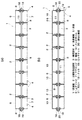
図1〜図6は、本発明の第1実施形態の床版橋1を示すものであって、図1(a)は本発明の第1実施形態の床版橋を示す縦断正面図であり、図2におけるA−A断面図に相当し、図1(b)は棒状部材が挿通配置されている部分での縦断正面図であり、図2におけるB−B断面図に相当する。図2は図1に示す床版橋の概略平面図、図3(a)は角形鋼管相互の接合部付近を示す側面図、同図(b)は同図(a)のC−C断面図、同図(c)
は同図(a)のD−D断面図、図4は、図2の一部の拡大平面図である。
図5は輪過重等の荷重が載荷した場合に、分割形支圧部材2から棒状部材3を介して隣接の角形鋼管4に応力を伝達する場合の伝達経路を示す説明図、図6は図5における応力伝達経路の詳細を示す説明図である。
FIGS. 1-6 shows the
FIG. 4 is a sectional view taken along the line DD of FIG. 4A, and FIG. 4 is a partially enlarged plan view of FIG.
FIG. 5 is an explanatory diagram showing a transmission path when stress is transmitted from the split-
図1に示す床版橋1において、角形鋼管の長手方向が橋軸方向であり、床版5は、橋軸方向に伸長する角形鋼管4を橋軸直角方向に複数本平行に配設し棒状部材3および支圧部材等が設置されて構成される。すなわち、橋幅に対して角形鋼管4一本あたりの上辺の幅は小さいから、この角形鋼管4を複数平行に配設し、相互間を分解可能に機械的に接合して一体化して床版5を構成し、その上面に、図示省略のコンクリートあるいはアスファルトよりなる舗装を打設して路面を構成することになるが、この路面を重量物である車両が走行することから角形鋼管4には過大な荷重(輪荷重等)が作用し、したがって、角形鋼管4を下側に撓ませる力や、角形鋼管4相互を引き離す大小のせん断力が常時作用することになる。このことから、複数の角形鋼管4の相互は分解可能に強固に結合一体化されているのが望ましく、かつ、上方からの力に対して耐荷重の大きい構造が望ましい。
In the
さらに、図1を参照して、本発明の床版橋1の構造について説明すると、上面板からなる上フランジ6と、下面板からなる下フランジ7と、上フランジ6および下フランジ7に一体に連接され、間隔をおいて対向する各腹板8を備え、一方または両方の腹板8には、部材長手方向に間隔をおいて、棒状部材3を挿通するための開口部9を腹板8の側面に複数(図示の形態の場合には、棒状部材3が8本、挿通される形態であるので、8箇所)備えている角形鋼管4とされている。
また、前記の角形鋼管4における上フランジ6には、前記開口部9に対応して、部材長手方向に長孔とされたハンドホール10が、部材長手方向に間隔をおいて複数(図2に示す形態では8つ)設けられている。前記のハンドホール10は、手動用回動工具あるいは電動用回動工具、棒状部材3を支持するための分割形支圧部材2、分割形支圧部材2あるいは角形鋼管4を接合するためのボルト11あるいはナットを挿入セットしたり、棒状部材3を吊り下げて仮支持するためのワイヤーを挿入配置するための長孔である(詳細は後記する)。
Further, the structure of the
Further, the
また、前記の角形鋼管4における腹板8側面の開口部9の周囲には、等角度間隔をおいて複数(図示の場合は、90度間隔をおいて4つ)のボルト挿通孔12が設けられ、ハンドホール10の周囲の上フランジ6には、複数(図示の場合には4つ)の雌ねじ孔13が設けられている。
In addition, a plurality of bolt insertion holes 12 (four in the illustrated case with 90 degree intervals) are provided at equiangular intervals around the
各角形鋼管4に設けられている前記の開口部9、ハンドホール10および各ボルト挿通孔12は、それぞれ部材長手方向で同じ位置となるように、間隔をおいて設けられている。前記の角形鋼管4としては、単管の鋼管が用いられ、床版橋における角形鋼管4は、特に潮風や雨水など錆の発生し易い環境で使用される場合もあることから、角形鋼管4の表面は、チタン、ステンレス、亜鉛鉄板、アルミニュウムなどの金属系の防食材料(図示を省略)で被覆してもよく、角形鋼管4の表面に塗装や亜鉛めっきを施しても良く、あるいは角形鋼管4を耐候性鋼仕様の角形鋼管を用いてもよい。
The
図1および図2では図示を省略しているが、橋脚あるいは橋台に台座モルタルあるいは支承上に橋軸方向に伸長し側面に開口部9を有する角形鋼管4が、橋軸直角方向に複数本並行に配設される。
橋幅方向の中間部に位置するすべての角形鋼管4は、隣り合う角形鋼管4の腹板8外側面相互を、密着させるように、各角形鋼管4は橋脚または橋台に載置される。橋幅方向の端部に位置する角形鋼管4は橋幅方向の内側面に位置する腹板8にのみ、部材長手方向に間隔をおいて開口部9を備えていると共に、その周りに、分割形支圧部材2を取り付ける
ためのボルト挿通孔を備えている。橋幅方向端部側に位置する角形鋼管4の橋幅方向外側に位置する腹板8には、部材長手方向に間隔をおいて開口部9を備えておらず、棒状部材3を中間部に位置する角形鋼管4に渡って貫通配置した後に、橋幅方向端部側の角形鋼管4は、横方向から設置されて、棒状部材3の端部は内側寄りの開口部9に挿入される。
Although not shown in FIGS. 1 and 2, a plurality of
Each
棒状部材3を、角形鋼管4に取り付けられる1つの支圧部材または複数個に分割された分割形支圧部材2に支承させて、分割形支圧部材2と棒状部材3間の力の伝達が、図5および図6に示すように、支圧力より伝達させるために、分割形支圧部材2の半径方向の先端部は、前記開口部9の中心よりに張り出すに設置され、また、分割形支圧部材2の半径方向の先端部は、支圧面を備えた開口部9とされている。前記の開口部9の支圧面は、前記棒状部材3の外周面と接触するメタルタッチ接触面である。前記の分割形支圧部材2は、2つの支圧部材構成片14が1組として組み合わされ、これらの支圧部材構成片14における凹部15が互いに向かい合うように、一組の支圧部材構成片14が組み合わされることにより、分割形支圧部材2が構成されている。前記凹部15の内周面が支圧面とされている。
橋幅方向に隣り合う各角形鋼管4の腹板8内側面に配置される各分割形支圧部材2は、各ハンドホール10から挿入されて、腹板8に重合するように縦向き当接され、分割形支圧部材2の半径方向内側面は、開口部9から張り出すように、開口部9の半径よりも小さい内径とされている。
橋幅方向端部を除く、中間部に隣り合う角形鋼管4における重合された腹板8に、前記の分割形支圧部材2のうち、下側に位置する下部支圧部材構成片14が配置されて、一方の下部支圧部材構成片14と、各腹板8と、他方の下部支圧部材構成片14の複数のボルト挿通孔にわたって挿通された複数のボルト11およびこれにねじ込まれるナットにより、摩擦接合により着脱可能に強固に固定されている。したがって、輪荷重が作用した場合は、図5および図6に示すように、分割形支圧部材2と角形鋼管4の腹板8との間、および角形鋼管4の腹板8相互間は、摩擦力により伝達される。
前記のように下部支圧部材構成片14を、中間部に位置する隣り合う角形鋼管4に設置した状態で、幅方向端部側から棒状部材3を下部支圧部材構成片14に支持させるように、中間部に位置するすべての角形鋼管4にわたって挿入配置する。
次いで、橋幅方向の端部側に位置する角形鋼管4を横方向から設置し、端部側の角形鋼管4における開口部9に棒状部材3の端部を挿入配置し、端部側の角形鋼管4の腹板8と、これに隣接する角形鋼管4の腹板8とに、下部支圧部材構成片14をそれぞれ配置して、これらに渡って挿通されるボルト11およびこれにねじ込まれるナットにより、中間部に位置する角形鋼管4と端部に位置する角形鋼管4および各分割形支圧部材2を着脱可能に一体化する。
次いで、ハンドホール10から、上部支圧部材構成片14を挿入して、中間部に位置する角形鋼管4の各腹板8と、端部に位置する角形鋼管4の内側の腹板8に、それぞれ分割形支圧部材2を挿入配置して、一方の上部支圧部材構成片14と各腹板8と他方の上部支圧部材構成片14とに渡ってボルト11を挿入すると共にこれにねじ込まれるナットにより締めこんで、着脱可能に一体化する。
前記の下部支圧部材構成片14と上部支圧部材構成片14との1組により、この形態では、分割形支圧部材2が形成されている。また、前記の下部支圧部材構成片14と上部支圧部材構成片14の半径方向内側の支圧面により、棒状部材支承用開口部22が形成され、棒状部材3の軸直角方向の外周面に接触するように形成されている。
前記の棒状部材3は、橋幅方向端部側に位置する角形鋼管4の橋幅方向端部側に位置する腹板8が開口部9を備えていないことにより、腹板8がストッパーの働きをし、端幅方向端部側に棒状部材3が抜け出さないようにされている。
次で、図1等では、図示が省略されているが、上フランジ6におけるハンドホール10を塞ぐべく、図16に示すように、鋼製蓋板16を上フランジ6に載置すると共に、鋼製蓋板16に挿通されると共に上フランジ6の雌ねじ孔にねじ込まれたボルト17により、
鋼製蓋板16を固定してハンドホール10を塞ぐ。このようにして、角形鋼管4が連結された床版5を形成する。前記の床版5の上に図示省略のコンクリートあるいはアスファルトよりなる舗装を打設して路面が形成される。また、図1等においては、図示を省略されているが、必要に応じ、適宜路肩、欄干等が設置されて床版橋1が構築される。
The rod-shaped
Each divided
The lower support
As described above, the lower supporting
Next, the
Next, the upper bearing
In this embodiment, the divided
In the rod-shaped
Next, although not shown in FIG. 1 and the like, the
The
前記のように、図1および図2に示す第1実施形態の床版橋1では、橋軸方向に伸長し、側面に開口部9を有する角形鋼管4が橋軸直角方向に複数本並行に配設され、前記開口部9に張り出すように前記角形鋼管4の側面内側に分割形支圧部材2が設置されると共に、隣り合う前記角形鋼管4の各腹板8と前記分割形支圧部材2とに渡って挿通配置されたボルト11により着脱可能に一体化され、棒状部材3を前記各角形鋼管4の前記開口部9および前記分割形支圧部材2の棒状部材支承用開口部22に渡って貫通配置して、前記棒状部材支承用開口部22により前記棒状部材3が支承されることにより、棒状部材3により橋軸直角方向にせん断キーを構成している床版橋1である。
As described above, in the
本発明においては、棒状部材3は、中空部材あるいは中実部材でもよく、中空部材である場合には、支圧力に対抗可能なような肉厚にする。棒状部材3としては、例えば、断面円形あるいは断面矩形等の鋼材が用いられ、例えば、棒鋼、鋼管、平鋼、異形鉄筋等の鋼材等を用いることもでき、外表面に凹凸を有する棒状部材3であると、コンクリートとの付着を高めることができる。
棒状部材3が、矩形断面である場合には、図14(c)(d)に示すように、下部支圧部材構成片14および上部支圧部材構成片14に、底部支承面とこれに接続する各側部支承面とからなる凹部15を設けて、これらの凹部15が上下に合わさるように閉合することで棒状部材支承用開口部22を形成するようにすればよい。棒状部材支承用開口部22は、閉合されていてもよいが、下部支圧部材構成片14および上部支圧部材構成片14が多少離反していてもよく、したがって、棒状部材支承用開口部22は、かならずしも閉鎖された状態でなくてもよく、下部支圧部材構成片14および上部支圧部材構成片14の凹部15の支承面(支圧面)、特に上下部の支承面(支圧面)が、棒状部材3の外周面に当接することで、輪荷重に対して支圧力を伝達することになる。前記の分割形支圧部材2の棒状部材支承用開口部22の周りには、等角度間隔をおいてボルト挿通孔12が設けられ、腹板8側のボルト挿通孔12と合致する位置に設けられている。棒状部材3の円形、矩形等の断面形態により、支圧部材(分割形支圧部材2)を図14(a)(b)あるいは図4(c)(d)その他の形態を適宜選択して使用すればよい。
In the present invention, the rod-shaped
When the rod-shaped
前記のように、棒状部材3に、分割形支圧部材2から支圧力が作用した場合、棒状部材3に支圧によるせん断力が作用することになるから、棒状部材3は、せん断キーとして作用している。また、輪荷重等の荷重載荷が一つの角形鋼管4に作用した場合、図5および図6に矢印で示すように、荷重載荷Fが作用している角形鋼管4側に設置されている分割形支圧部材2には、摩擦F1により伝達され、その分割形支圧部材2から棒状部材3には支圧F2により伝達される。また棒状部材3から隣接する角形鋼管4に設置の分割形支圧部材2には、支圧力F3が伝達され、分割形支圧部材2から隣接の角形鋼管4に摩擦F4により伝達される。
また、隣接する角形鋼管4に摩擦により伝達された下向きの力F5は、隣接する角形鋼管4における図示省略の他方の支圧部材に摩擦力により伝達し、支圧部材から支圧力を棒状部材3に作用する。このように、分割形支圧部材2および棒状部材3を介して、隣接する角形鋼管4に輪荷重等による載荷力を伝達することができる。
図6には、各部間の応力の伝達を矢印で示している。角形鋼管4に作用する載荷荷重は上フランジ6に等分布荷重が作用すると仮定している。
As described above, when a support pressure is applied to the rod-shaped
Further, the downward force F5 transmitted to the adjacent
In FIG. 6, the transmission of stress between each part is indicated by an arrow. It is assumed that the load applied to the
なお、応力伝達経路に関して、本発明の床版橋1では、棒状部材3が配置されている部分においては、前記角形鋼管4の板厚(高さ寸法)を考慮した剛性に比して前記棒状部材
3の剛性が高い場合は、棒状部材3が主な応力伝達部材(支圧力伝達部材)として働き、前記角形鋼管4の板厚(高さ寸法)を考慮した剛性に比して、前記棒状部材3の剛性が低い場合は、隣り合う前記角形鋼管4による摩擦による伝達と、棒状部材3による支圧力伝達作用の2つの作用により、輪荷重等の載荷荷重による応力は伝達される。
輪荷重等の載荷荷重が角形鋼管4に作用した場合、角形鋼管4は微小変形し撓むようになるから、棒状部材3と支圧部材(または分割形支圧部材2)2の凹部15とが近接していれば、メタルタッチすることができる。また、下部支圧部材構成片14の両側部上面と上部支圧部材構成片14の両側部下面とが、図3(a)(c)に示すようにタッチしていても、多少離反していても、一方の角形鋼管4の腹板8から支圧部材(または分割形支圧部材2)2を介した載荷荷重の成分は、支圧部材(または分割形支圧部材2)2が棒状部材3にタッチした時点で、棒状部材3に支圧力が伝達され、その棒状部材3から隣接の角形鋼管4側の支圧部材(または分割形支圧部材2)2の下側に支圧力が伝達される。
In addition, regarding the stress transmission path, in the
When a load such as a wheel load is applied to the
この形態の棒状部材3の長さ寸法は、橋幅方向で、一端部側の角形鋼管4の外側の腹板8の内側から、他端部側の角形鋼管4の内側の腹板8に設置される分割形支圧部材2までの距離以上の寸法で、かつ、橋幅方向両端部の角形鋼管4の外側の腹板8の内側間の寸法よりも短い寸法に設定されている。
The length dimension of the rod-shaped
なお、図示を省略するが、図1および図2に示すような床版5を並行して複数設置した床版橋としてもよい。
Although not shown, a floor slab bridge in which a plurality of
図7〜図9は、本発明の第2実施形態の床版橋を示すものであって、図7(a)は本発明の第2実施形態の床版橋を示す縦断正面図であり、図8におけるE−E断面図に相当し、図7(b)は棒状部材が挿通配置されている部分での縦断正面図であり、図8におけるE−E断面図に相当する。図8は図7に示す床版橋の概略平面図、図9は図7の一部の拡大平面図である。 FIGS. 7-9 shows the floor slab bridge of 2nd Embodiment of this invention, Comprising: Fig.7 (a) is a vertical front view which shows the floor slab bridge of 2nd Embodiment of this invention, 8 corresponds to a cross-sectional view taken along line EE in FIG. 8, and FIG. 7B is a longitudinal front view at a portion where the rod-shaped member is inserted and arranged, and corresponds to a cross-sectional view taken along line EE in FIG. 8 is a schematic plan view of the floor slab bridge shown in FIG. 7, and FIG. 9 is a partially enlarged plan view of FIG.
この形態と前記実施形態の相違する部分は、橋幅方向端部側に位置する角形鋼管4の各腹板8の開口部9を設け、棒状部材3をすべての角形鋼管4の側面開口部9に渡って貫通するように配置し、棒状部材3の両端部にナット18およびロックナット19を装着することで、ナット18をストッパーとして機能させて、棒状部材3の抜け出し防止を図るようにした形態である。なお、前記実施形態と同様な部分には、同様な符号を付し、相違する部分を主に説明する。
この形態では、すべての角形鋼管4を並行して設置し、橋幅方向端部側の角形鋼管4における外側の腹板8の両側に下部支圧部材構成片14を設置し、橋幅方向端部および中間部に位置するすべての角形鋼管4に下部支圧部材構成片14を設置した後、棒状部材3が挿通される。
また、棒状部材3の両端部には、雄ねじ軸部20を備えており、棒状部材3の端部には、ナット18が締結され、その外側において棒状部材3にロックナット19がねじ込まれて、棒状部材3は、橋幅方向に移動不能にされている。
The difference between this embodiment and the above embodiment is that an
In this embodiment, all the
Further, both end portions of the rod-shaped
この形態においては、棒状部材3としては、図13(a)(b)に示すように、中実で断面円形の棒状部材3の両端部に雄ねじ部軸部20を設ける形態でもよく、同図(e)(f)に示すように、角形中空部材からなる棒状部材3の両端部に雄ねじ部軸部20を設ける形態でもよい。また、図13(c)(d)に示すように、中空で断面円形の棒状部材3の両端部に雄ねじ部軸部20を設ける形態でもよく、同図(g)(h)に示すように、角形中空部材からなる棒状部材3の両端部に雄ねじ部軸部20を設ける形態でもよい。
棒状部材3の中間部の外形が、矩形状である場合には、前記したように、分割形支圧部材2の棒状部材支承用開口部22を矩形状にすればよい。前記実施形態と同様、この形態においても、分割形支圧部材2に代えて、1枚の支圧部材としてもよい。
In this embodiment, as shown in FIGS. 13 (a) and 13 (b), the rod-
When the outer shape of the intermediate portion of the rod-shaped
図10〜図12は、本発明の第3実施形態の床版橋を示すものであって、図10(a)は縦断正面図であり、図11におけるG−G断面図に相当し、図10(b)は棒状部材が挿通配置されている部分での縦断正面図であり、図11におけるH−H断面図に相当する。図11は図10に示す床版橋の概略平面図、図12は図11の一部の拡大平面図である。 FIGS. 10-12 shows the floor slab bridge of 3rd Embodiment of this invention, Comprising: Fig.10 (a) is a vertical front view, is equivalent to GG sectional drawing in FIG. 10 (b) is a longitudinal front view at a portion where the rod-like member is inserted and arranged, and corresponds to a cross-sectional view taken along line HH in FIG. 11 is a schematic plan view of the floor slab bridge shown in FIG. 10, and FIG. 12 is an enlarged plan view of a part of FIG.
この形態と前記第2実施形態と相違する部分は、前記第2実施形態においては、棒状部材3が1本ものの棒状部材とされているが、この形態では、棒状部材3は、同一の橋軸直角方向断面内で、複数本(図示の場合は2本)の棒状部材3を、角形鋼管4の開口部9および分割形支圧部材2の棒状部材支承用開口部22に渡って貫通配置されている形態の床版橋1とされている。
また、中央部に位置する角形鋼管4における中央よりに位置する腹板8には、その高さ方向の上部(上フランジ6寄り)および下部(下フランジ7寄り)に位置した部分に、部材長手方向に間隔をおいて多数のボルト挿通孔が設けられ、中央寄りの各角形鋼管4の腹板8相互は重合されて、上下部の複数のボルト11(またはボルト・ナット11)により、中央部に位置する角形鋼管4が接合されている。中央部に位置する角形鋼管4の中央部よりの腹板8には、開口部9が設けられていない形態の角形鋼管4が使用されているが、開口部9を設ける形態でもよい。
The difference between this embodiment and the second embodiment is that, in the second embodiment, the rod-shaped
In addition, the
前記の第3実施形態の床版橋1を組み立てる場合には、例えば、図10を参照して説明すると、中央部に位置する角形鋼管4の中央部よりの腹板8には、開口部9が設けられていない形態の角形鋼管4を使用する場合には、中央部より左に位置する角形鋼管4を順次設置し、ハンドホール10から下部支圧部材構成片14を設置した状態において、橋幅方向端部側の角形鋼管4の開口部9側から棒状部材3を挿入配置するようにしてもよく、中央部よりから棒状部材3を挿入配置する場合には、中央部よりの角形鋼管4を設置する前に棒状部材3を配置した後、中央部よりの角形鋼管4を設置し、棒状部材3を中央部よりの角形鋼管4内に押し出すか、または引き出すか、あるいは、中央部よりの角形鋼管4を橋幅方向にスライドイド移動させて、棒状部材3を挿入配置することでもよい。
また、既設の中央部より左の角形鋼管4の腹板8に、新設の中央部より右の角形鋼管4の腹板8が重合するように設置し、以下順次、右側に位置する角形鋼管4を設置し、下部支圧部材構成片14を設置した後、棒状部材3を橋幅方向他端側から挿入配置し、上部支圧部材構成片14をハンドホール10から挿入して、棒状部材3に当接するように配置すると共に、中間部に位置する角形鋼管4では、隣り合う角形鋼管4の各腹板8およびその両側の上部支圧部材構成片14とに渡って挿通配置されたボルト・ナット23により着脱可能に固定し、橋幅方向端部側の角形鋼管4では、外側に位置する腹板8の内外両側に配置された上部支圧部材構成片14のボルト挿通孔にわたってボルト11を挿通すると共にこれにねじ込まれたナットにより着脱可能に上部支圧部材構成片14を固定する。
In the case of assembling the
In addition, it is installed so that the
前記の場合は、前記棒状部材3は、同一の橋軸直角方向断面内で、2本の棒状部材3を間隔をおいて直列に配置する形態を示したが、例えば、図示を省略するが、図10(b)右端の角形鋼管4に、同図中央より左側の角形鋼管4と同様な角形鋼管4を配置して、各腹板8の外側に分割形支圧部材2を配置して、ボルト・ナット11により着脱可能に固定し、さらに隣接するように角形鋼管4を配置する形態にすると、同一の橋軸直角方向断面内で、3本以上の棒状部材3を配置する形態の床版橋1とすることができる。
In the above case, the rod-shaped
前記各実施形態において、分割形支圧部材2として板状の分割形支圧部材2の形態を示したが、本発明を実施する場合、図17に示すように、分割形支圧部材2に、半筒状のガイド部材21を設けるようにしてもよい。前記のガイド部材21は、棒状部材3を橋幅方向にスライド移動する場合のガイド部と、支圧力を伝達する支承面を備えた形態のガイド
部材としてもよい。
前記のガイド部材21におけるガイド面は、そのガイド部材21の軸方向(棒状部材3の軸方向)で、中間部から外側が、部材軸方向基端部に向かって漸次拡径するように傾斜するテーパー状のガイド面を備えたガイド部材21であってもよい。
前記のガイド部材21としては、分割形支圧部材2に直角に板状のガイド部材を設けるようにしてもよい。分割形支圧部材2が鋼板等の鋼材である場合には、鋼製のガイド部材21を溶接により固定するようにすればよい。なお、分割形支圧部材2は1枚ものでもよく、前記実施形態のように上部支圧部材構成片14と下部支圧部材構成片14との2つまたはそれ以上の複数の部材片により構成するようにしてもよい。
また、図示を省略するが、支圧部材が、分割形支圧部材2ではなく、1枚ものの支圧部材である場合には、部材軸方向基端部に向かって漸次拡径するように傾斜するテーパー筒状のガイド部材(21)の基端部を、棒状部材挿通用開口部22に固定してもよい。テーパー筒状のガイド部材(21)の基端部内面と棒状部材挿通用開口部22の内径を同じに、同心状に設けるとよい。図示の形態では、分割形支圧部材2は、上下2つに分割されている形態を示したが、3つまたはこれ以上に分割した形態でもよい。
In each of the above-described embodiments, the form of the plate-shaped divided
The guide surface of the
As the
Although illustration is omitted, when the bearing member is not a divided bearing
前記第1実施形態においては、複数本並行に配設する角形鋼管4の両端に位置する端部角形鋼管4において、他の角形鋼管4と接しない側(外側)の腹板8に開口部9を設けないことにより、抜け出し防止手段としているが、他の角形鋼管4と接しない側(外側)の腹板8に開口部9を設ける場合には、図示を省略するが、閉塞板をボルトまたはボルト・ナットにより固定することにより、棒状部材3の抜け出し防止手段としてもよく、棒状部材3の両端部にナットなどのストッパーを設けることにより、棒状部材3の抜け出し防止手段としてもよい。
In the first embodiment, in the end
前記実施形態においては、分割形支圧部材2における下部支圧部材構成片14を、棒状部材3を開口部から貫通配置する前に、設置するようにしているが、棒状部材3を貫通配置した後に、適宜の仮支持部材により棒状部材3を支持した状態で、分割形支圧部材2を設置するようにし、前記の仮支持部材を取り外すようにしてもよい。前記の仮支持部材としては、図示を省略するが、ハンドホール10を横断するように上フランジ6に、脚部付支持台を設け、その脚部付支持台の下側に、前記脚部付支持台に支持させるように、ねじ機構により昇降可能に支持部材を設け、前記支持部材に棒状部材3を支承する鋼線等の両端部を着脱可能に取り付けることにより、棒状部材3を開口部9から浮かせた状態で仮支持し、その状態で、分割形支圧部材2を構成する下部支圧部材構成片14、あるいは上部支圧部材構成片14を設置するようにしてもよい。
前記以外にも、ハンドホール10を横断するように上フランジ6に、仮支持部材を設け、前記仮支持部材に棒状部材3を支承する鋼線等ワイヤーの両端部を着脱可能に取り付け、前記仮支持部材の両端部を、上フランジ6に配置の一対のL形アームの下端部にそれぞれ係止させて、L形アームの上部を回動することより、てこ作用により下端部を上昇させることで、棒状部材3を上昇させて、その状態を保持した状態で、下部支圧部材構成片14を設置するようにしてもよい。
したがって、また、棒状部材3を角形鋼管4における腹板8の開口部9に支承させた状態で、それぞれの分割形支圧部材2を設置する時に、棒状部材3を持ち上げて、棒状部材3を支承させつつ、分割形支圧部材2を設置するようにしてもよい。
前記のように、棒状鋼材を各角形鋼管の開口部に渡って挿通配置した後、棒状鋼材を適宜支承した状態で、支圧部材を配置してボルトにより腹板と一体化させて棒状部材を支承すればよいので、開口径の大きい開口部から棒状鋼材を挿入して配置することができるため、棒状鋼材の挿入による貫通配置が容易になる。
In the above-described embodiment, the lower support
In addition to the above, a temporary support member is provided on the
Therefore, when the divided
As described above, after the rod-shaped steel material is inserted and arranged over the openings of the respective square steel pipes, with the rod-shaped steel material supported appropriately, the support member is arranged and integrated with the belly plate by the bolts to form the rod-shaped member. Since it only needs to be supported, the rod-shaped steel material can be inserted and arranged from the opening having a large opening diameter, and therefore, the penetrating arrangement by inserting the rod-shaped steel material becomes easy.
次に、前記実施形態の床版橋1を構築する方法について説明する。
Next, a method for constructing the
図1〜図6に示す形態の床版橋の構築方法としては、下部支圧部材構成片14を先に設置し、その後、棒状部材3を開口部9に渡って貫通配置し、その後、上部支圧部材構成片14を設置する形態では、次のような方法により床版橋を構築すればよい。
すなわち、橋軸方向に伸長し、側面に開口部9を有する角形鋼管4を橋軸直角方向に複数本並行に配設し、前記角形鋼管4の腹板8に設ける前記開口部9に張り出すように前記開口部の下側に分割形支圧部材2のうち下側部分(下部支圧部材構成片14)を設置し、隣り合う前記角形鋼管4の各腹板8と前記分割形支圧部材2のうち下側部分(下部支圧部材構成片14)とに渡ってボルトを挿通させて一体化する。そして、棒状部材3を前記分割形支圧部材2の前記棒状部材支承用開口部22に渡って貫通配置した後、前記分割形支圧部材2の残りの部分(上部支圧部材構成片14)を前記開口部9に張り出すように前記腹板8側面に配置し、隣り合う前記角形鋼管4の各腹板8と前記分割形支圧部材2の残りの部分(上部支圧部材構成片14)とに渡ってボルト11を挿通させて、前記ボルトに固定されるナットをねじ込んで一体化して、床版橋1を構築する方法がある。
As a construction method of the floor slab bridge of the form shown in FIGS. 1 to 6, the lower bearing
That is, a plurality of
また、棒状部材3を開口部9に渡って貫通配置した後、棒状部材3を前記仮支持部材あるいは設置された分割形支圧部材2等により支承しつつ、分割形支圧部材2を設置する形態では、次のような構築方法とすればよい。
すなわち、橋軸方向に伸長し、側面に開口部9を有する角形鋼管4を橋軸直角方向に複数本並行に配設し、棒状部材3を前記各角形鋼管4の開口部9に渡って貫通配置した後、前記棒状部材3を支承させつつ、分割形支圧部材2を前記角形鋼管4の腹板8に設ける前記開口部9に張り出すように設置し、隣り合う前記角形鋼管4の各腹板8と前記分割形支圧部材2とに渡ってボルト11を挿通させて、前記ボルト11にねじ込まれるナットを締めこんで一体化して、床版橋1を構築するようにしてもよい。
Further, after the bar-shaped
That is, a plurality of
また、図1〜図6に示す形態において、分割形支圧部材2ではなく、1枚ものの支圧部材である場合(図示を省略)には、次のような構築方法とすればよい。
すなわち、橋軸方向に伸長し、側面に開口部9を有する角形鋼管4を橋軸直角方向に複数本並行に配設し、棒状部材3を前記各角形鋼管4の開口部9に渡って貫通配置させつつ、支圧部材の棒状部材支承用開口部22に貫通配置した後、隣り合う前記角形鋼管4の各腹板8と前記支圧部材2とに渡ってボルト11を挿通させて、前記ボルト11にねじ込まれるナットを締め込んで一体化する構築方法でもよい。
Moreover, in the form shown in FIGS. 1-6, when it is not the division | segmentation
That is, a plurality of
また、図7〜図9に示す形態で、分割形支圧部材2における下部支圧部材構成片14を設置した後、棒状部材3を貫通配置し、その後、上部支圧部材構成片14を設置する形態では、次のような構築方法とすればよい。
Further, in the form shown in FIG. 7 to FIG. 9, after installing the lower support
すなわち、橋軸方向に伸長し、側面に開口部9を有する角形鋼管4を橋軸直角方向に複数本並行に配設し、前記角形鋼管4の腹板8に設ける前記開口部9に張り出すように前記開口部9の下側に分割形支圧部材2のうち下側部分(下部支圧部材構成片14)を設置し、隣り合う前記角形鋼管4の各腹板8と前記分割形支圧部材2のうち下側部分(下部支圧部材構成片14)とに渡ってボルト11を挿通させて、前記ボルト11にねじ込まれるナットを締め込むことで、一体化し、棒状部材3を前記分割形支圧部材2の前記棒状部材支承用開口部22に渡って貫通配置した後、前記分割形支圧部材2の残りの部分(上部支圧部材構成片14)を前記開口部9に張り出すように前記腹板8に設置し、隣り合う前記角形鋼管4の各腹板8と前記分割形支圧部材2の残りの部分(上部支圧部材構成片14)とに渡ってボルト11を挿通させて、前記ボルト11にねじ込まれるナットを締め込んで一体化し、さらに、前記棒状部材3の両端を前記端部角形鋼管4の腹板8または前記分割形支圧部材2の位置でナット18により締め付ける構築方法でもよい。
前記のように、前記棒状部材3の両端を前記端部角形鋼管4の腹板8または前記分割形支圧部材2の位置でナット18により締め付けるようにすると、各角形鋼管4の側面相互
を、腹板8およびその腹板8に渡って挿通配置されるボルト11およびこれにねじ込まれるナットと、棒状部材3の両方で確実に、各角形鋼管4の腹板8を圧着させて、圧着された腹板8間の摩擦抵抗力を高めることができ、輪荷重等の載荷荷重が作用した場合に横方向の角形鋼管に広く分散させることができ、耐久力を高めることができる。
なお、棒状部材3の端部にねじ込まれるナットを直接、角形鋼管4の腹板8に当接させる場合には、橋幅方向で、腹板8の内側に支圧部材2を設け、腹板8の外側の支圧部材を省略してもよい。この場合には、橋幅方向で、腹板8の内側の支圧部材2と腹板8とに渡って、ボルト11を挿通し、これにねじ込まれるナットにより、支圧部材2を所定の位置に設置するようにすればよい。
That is, a plurality of
As described above, when both ends of the rod-shaped
In addition, when making the nut screwed in the edge part of the rod-shaped
また、図7に示す形態において、棒状部材3を角形鋼管4に貫通配置した後、分割形支圧部材2における下部支圧部材構成片14を設置、その後、上部支圧部材構成片14を設置するような形態では、次のような構築方法とすればよい。
Further, in the embodiment shown in FIG. 7, after the rod-
すなわち、橋軸方向に伸長し、側面に開口部9を有する角形鋼管4を橋軸直角方向に複数本並行に配設し、前記棒状部材3を前記各角形鋼管4の開口部9に渡って貫通配置した後、前記棒状部材3を支承させつつ、分割形支圧部材2を前記角形鋼管4の腹板8に設ける前記開口部9に張り出すように設置し、隣り合う前記角形鋼管4の各腹板8と前記分割形支圧部材2とに渡ってボルト11を挿通させて、前記ボルト11にねじ込まれるナットを締め込むことで一体化し、さらに、前記棒状部材3の両端を前記端部角形鋼管4の腹板8または前記分割形支圧部材2の位置でナット18により締め付けるようにする床版橋1の構築方法であってもよい。
That is, a plurality of
また、図7に示す形態において、図示を省略するが、分割形支圧部材2ではなく、1枚ものの支圧部材2である形態では、次のような構築方法とすればよい。
すなわち、橋軸方向に伸長し、側面に開口部9を有する角形鋼管4を橋軸直角方向に複数本並行に配設し、棒状部材3を前記各角形鋼管4の開口部に渡って貫通配置させつつ、支圧部材2の前記棒状部材支承用開口部22に貫通配置した後、隣り合う前記角形鋼管4の各腹板8と前記支圧部材2とに渡ってボルト11を挿通させて、前記ボルト11にねじ込まれるナットを締め込むことで一体化し、さらに、前記棒状部材3の両端を前記端部角形鋼管4の腹板8または前記支圧部材2の位置でナット18により締め付ける床版橋1の構築方法としてもよい。
Although not shown in the form shown in FIG. 7, the following construction method may be used in the form of a
That is, a plurality of
本発明を実施する場合、腹板8と、その片側面または両側面に配置される支圧部材(または分割形支圧部材2)を摩擦接合する場合、一方の支圧部材(または分割形支圧部材)2に雌ねじ孔を設けて、他方の支圧部材2側の孔からボルトを挿通してその雄ねじ軸部をねじ込むようにしてもよい。また、腹板8の片側面に支圧部材(または分割形支圧部材)2を配置する場合には、支圧部材側に雌ねじ孔を設けて、腹板側からボルトを挿通してその雄ねじ軸部を支圧部材にねじ込むようにしてもよい。
When carrying out the present invention, when the
(床版橋を分解する場合について)
前記の各実施形態の床版橋1を分解して撤去する場合には、前記の構築方法と逆の手順により、分解して撤去するようにすればよい。そのため、本発明の床版橋1は、本設の床版橋として用いたり、仮設の床版橋として用いたりすることができ、撤去する場合も容易に短工期で撤去することができる。
例えば、図1から図6に示す形態の床版橋1を分解撤去する場合には、橋幅方向端部側の角形鋼管4の幅方向端部側の腹板8に開口部9を備えていない形態であるので、端部内側の支圧部材(または分割形支圧部材)2を固定しているボルト11を取り外して端部側の支圧部材(または分割形支圧部材)2を撤去し、棒状部材3を橋幅方向に引き出すか、または、端部側および中間部に位置する各分割形支圧部材2の上側部分(上部支圧部材構
成片14)を固定しているボルト11を取り外して、上側部分(上部支圧部材構成片14)をハンドホール10から取り除き、棒状部材3を橋幅方向に引き出して取り除き、端部および中間部に位置する支圧部材(または分割形支圧部材)2の下側部分(下部支圧部材構成片14)を固定しているボルト11を取り外して、下側部分(下部支圧部材構成片14)を撤去し、最後に各角形鋼管4を吊り上げ搬送等により撤去するようにすればよい。
また、橋幅方向の端部の角形鋼管4側面の開口部9を閉塞板により閉塞する場合には、その閉塞板が棒状部材3を引き抜く場合の邪魔になる場合には、棒状部材3を引き抜く前の適宜の時期に撤去するようにすればよい。
(When disassembling the floor slab bridge)
When the
For example, when the
Further, when the
また、図7から図9に示す形態の床版橋1を分解撤去する場合には、棒状部材3端部のロックナット19およびナット18を取り外し、棒状部材3を橋幅方向に引き出すか、または、端部側および中間部に位置する各分割形支圧部材2の上側部分(上部支圧部材構成片14)を固定しているボルト11を取り外して、上側部分(上部支圧部材構成片14)をハンドホール10から取り除き、棒状部材3を橋幅方向に引き出して取り除き、端部および中間部に位置する支圧部材(または分割形支圧部材)2の下側部分(下部支圧部材構成片14)を固定しているボルト11を取り外して、下側部分(下部支圧部材構成片14)を撤去し、最後に各角形鋼管4を吊り上げ搬送等により撤去するようにすればよい。
When the
また、図10から図12に示す形態の床版橋1を分解撤去する場合には、各棒状部材3端部のロックナット19およびナット18を取り外し、棒状部材3を橋幅方向に引き出すか、または、端部側および中間部に位置する各分割形支圧部材2の上側部分(上部支圧部材構成片14)を固定しているボルト11を取り外して、上側部分(上部支圧部材構成片14)をハンドホール10から取り除き、棒状部材3を橋幅方向に引き出して取り除き、端部および中間部に位置する支圧部材(または分割形支圧部材)2の下側部分(下部支圧部材構成片14)を固定しているボルト11を取り外して、下側部分(下部支圧部材構成片14)を撤去し、中央部の角形鋼管4を接合しているボルト・ナット11を、角形鋼管4の搬送撤去前のいずれか適宜の時期に取り外し、最後に各角形鋼管4を吊り上げ搬送等により撤去するようにすればよい。
なお、前記の撤去方法においては、床版橋1に設けられている舗装、欄干等は、事前に撤去しておく。
When the
In addition, in the said removal method, the pavement, the railing, etc. which are provided in the
なお、棒状部材3の周りに配置される支圧部材(または分割形支圧部材2)とは、メタルタッチして支圧応力を伝達するようにしておくことが望ましいが、支圧応力を伝達させる前提で、せん断キー(換言すると、横桁を兼ねたせん断キー)としての棒状部材3を角形鋼管4に挿通する場合に、棒状鋼材を1mm以下の精度で複数の角形鋼管に挿入すればよい。
In addition, it is desirable that the supporting pressure member (or the divided supporting member 2) arranged around the rod-shaped
1 床版橋
2 分割形支圧部材
3 棒状部材
4 角形鋼管
5 床版
6 上フランジ
7 下フランジ
8 腹板
9 開口部
10 ハンドホール
11 ボルト
12 ボルト挿通孔
13 雌ねじ孔
14 支圧部材構成片
15 凹部
16 鋼製蓋板
17 ボルト
18 ナット
19 ロックナット
20 雄ねじ軸部
21 ガイド部材
22 棒状部材支承用開口部
23 ボルト・ナット
DESCRIPTION OF
Claims (15)
前記開口部に張り出すように前記角形鋼管の側面内側に支圧部材が配置されると共に、
隣り合う前記角形鋼管の各腹板と前記支圧部材とに渡って挿通配置されたボルトにより一体化され、
棒状部材を前記各角形鋼管の前記開口部および前記支圧部材の棒状部材支承用開口部に渡って貫通配置して、
前記棒状部材支承用開口部により前記棒状部材が支承されることにより、
橋軸直角方向にせん断キーを構成していることを特徴とする床版橋。 A plurality of square steel pipes extending in the direction of the bridge axis and having openings on the side surfaces are arranged in parallel in the direction perpendicular to the bridge axis,
A bearing member is arranged inside the side surface of the rectangular steel pipe so as to overhang the opening,
It is integrated by bolts that are inserted through the abdomen and the bearing member of the adjacent square steel pipe,
A bar-shaped member is disposed through the opening of each square steel pipe and the bar-shaped member support opening of the bearing member,
By supporting the rod-shaped member by the opening for supporting the rod-shaped member,
A floor slab bridge that has shear keys in the direction perpendicular to the bridge axis.
他の角形鋼管と接しない側の腹板に前記開口部を設けない、
または前記開口部を塞ぐ閉塞板を設置する、
もしくは前記棒状部材の両端にストッパーを設置することにより、棒状部材の抜け出し防止手段を有することを特徴とする請求項1に記載の床版橋。 In the end square steel pipes located at both ends of the square steel pipes arranged in parallel,
Do not provide the opening in the belly plate on the side not in contact with other square steel pipes,
Or installing a blocking plate to close the opening,
The floor slab bridge according to claim 1, further comprising means for preventing the rod-shaped member from slipping out by installing stoppers at both ends of the rod-shaped member.
前記開口部に張り出すように前記角形鋼管の側面内側に支圧部材が配置されると共に、
隣り合う前記角形鋼管の各腹板と前記支圧部材とに渡って挿通配置されたボルトにより着脱可能に一体化され、
棒状部材を前記各角形鋼管の前記開口部および前記支圧部材の棒状部材支承用開口部に渡って貫通配置して、
前記棒状部材支承用開口部により前記棒状部材が支承されることにより、
橋軸直角方向にせん断キーを構成し、
前記棒状部材の両端をナットで締め付けることにより、
前記角形鋼管相互をさらに締結したことを特徴とする床版橋。 A plurality of square steel pipes extending in the direction of the bridge axis and having openings on the side surfaces are arranged in parallel in the direction perpendicular to the bridge axis,
A bearing member is arranged inside the side surface of the rectangular steel pipe so as to overhang the opening,
It is detachably integrated by bolts that are inserted and arranged across the abdominal plate of the adjacent square steel pipe and the bearing member,
A bar-shaped member is disposed through the opening of each square steel pipe and the bar-shaped member support opening of the bearing member,
By supporting the rod-shaped member by the opening for supporting the rod-shaped member,
Configure shear keys in the direction perpendicular to the bridge axis,
By tightening both ends of the rod-shaped member with nuts,
A floor slab bridge in which the square steel pipes are further fastened together.
または複数個に分割された1組の分割形支圧部材、
または前記分割形支圧部材およびこれに前記棒状部材の挿通を補助するガイド部材を備えた1組の支圧部材構成片よりなる分割形支圧部材により構成され、
前記支圧部材および前記分割形支圧部材は、
前記棒状部材の外周面と接触するメタルタッチ接触面を備えた棒状部材支承用開口部または凹部を有し、重合される前記角形鋼管の腹板の両側または片側に設置されることを特徴とする請求項1〜3のいずれか1項に記載の床版橋。 The supporting member is one supporting member,
Or a set of divided support members divided into a plurality of parts,
Alternatively, it is constituted by a split-type support member composed of a set of support-member-constituting pieces provided with the split-type support member and a guide member for assisting the insertion of the rod-like member therein,
The bearing member and the split bearing member are
It has a bar-shaped member support opening or recess having a metal touch contact surface that comes into contact with the outer peripheral surface of the bar-shaped member, and is installed on both sides or one side of the belly plate of the square steel pipe to be polymerized. The floor slab bridge according to any one of claims 1 to 3.
重合される前記角形鋼管の腹板の両側または片側に設置されることを特徴とする請求項1〜4のいずれか1項に記載の床版橋。 The bearing member and the split bearing member are
The floor slab bridge according to any one of claims 1 to 4, wherein the floor slab bridge is installed on both sides or one side of a belly plate of the square steel pipe to be polymerized.
前記支圧部材を設置する断面の上フランジに作業用のハンドホールを有することを特徴とする請求項1〜8のいずれか1項に記載の床版橋。 The square steel pipe is
The floor slab bridge according to any one of claims 1 to 8, wherein a work hand hole is provided on an upper flange of a section where the bearing member is installed.
前記角形鋼管の腹板に設ける前記開口部に張り出すように前記開口部の下側に分割形支圧部材のうち下側部分を配置し、
隣り合う前記角形鋼管の各腹板と前記分割形支圧部材のうち下側部分とに渡ってボルトを挿通させて一体化し、
棒状部材を前記分割形支圧部材の前記棒状部材支承用開口部に渡って貫通配置した後、前記分割形支圧部材の残りの部分を前記開口部に張り出すように前記腹板に設置し、
隣り合う前記角形鋼管の各腹板と前記支圧部材の残りの部分とに渡ってボルトを挿通させて一体化することを特徴とする床版橋の構築方法。 A plurality of square steel pipes extending in the direction of the bridge axis and having openings on the side surfaces are arranged in parallel in the direction perpendicular to the bridge axis,
The lower part of the split-type supporting member is arranged below the opening so as to overhang the opening provided on the belly plate of the square steel pipe,
The bolts are inserted and integrated over each belly plate of the adjacent square steel pipe and the lower part of the split-type support member,
After the rod-shaped member is disposed through the opening for supporting the rod-shaped member of the split-type support member, the remaining portion of the split-type support member is installed on the abdominal plate so as to project to the opening. ,
A method for constructing a floor slab bridge, wherein bolts are inserted and integrated between each abdominal plate of the adjacent square steel pipe and the remaining portion of the bearing member.
棒状部材を前記各角形鋼管の開口部に渡って貫通配置した後、
前記棒状部材を支承させつつ、分割形支圧部材を前記角形鋼管の腹板に設ける前記開口部に張り出すように設置し、
隣り合う前記角形鋼管の各腹板と前記支圧部材とに渡ってボルトを挿通させて一体化することを特徴とする床版橋の構築方法。 A plurality of square steel pipes extending in the direction of the bridge axis and having openings on the side surfaces are arranged in parallel in the direction perpendicular to the bridge axis,
After arranging the rod-shaped member through the opening of each square steel pipe,
While supporting the rod-shaped member, a split-type support member is installed so as to overhang the opening provided in the belly plate of the rectangular steel pipe,
A construction method for a floor slab bridge, wherein bolts are inserted and integrated between the abdominal plates of the adjacent square steel pipes and the bearing member.
棒状部材を前記各角形鋼管の開口部に渡って貫通配置させつつ、
支圧部材の前記棒状部材支承用開口部に貫通配置した後、
隣り合う前記角形鋼管の各腹板と前記支圧部材とに渡ってボルトを挿通させて一体化することを特徴とした床版橋の構築方法。 A plurality of square steel pipes extending in the direction of the bridge axis and having openings on the side surfaces are arranged in parallel in the direction perpendicular to the bridge axis,
While arranging the rod-shaped member through the opening of each square steel pipe,
After penetrating the rod-shaped member support opening of the support member,
A construction method for a floor slab bridge, wherein a bolt is inserted through and integrated with each belly plate of the adjacent square steel pipe and the bearing member.
前記角形鋼管の腹板に設ける前記開口部に張り出すように前記開口部の下側に分割形支圧部材のうち下側部分を配置し、
隣り合う前記角形鋼管の各腹板と前記分割形支圧部材のうち下側部分とに渡ってボルトを挿通させて一体化し、
棒状部材を前記分割形支圧部材の前記棒状部材支承用開口部に渡って貫通配置した後、
前記分割形支圧部材の残りの部分を前記開口部に張り出すように前記腹板に設置し、
隣り合う前記角形鋼管の各腹板と前記支圧部材の残りの部分とに渡ってボルトを挿通させて一体化し、
さらに、前記棒状部材の両端を前記端部角形鋼管の腹板または前記支圧部材の位置でナットにより締め付けることを特徴とした床版橋の構築方法。 A plurality of square steel pipes extending in the direction of the bridge axis and having openings on the side surfaces are arranged in parallel in the direction perpendicular to the bridge axis,
The lower part of the split-type supporting member is arranged below the opening so as to overhang the opening provided on the belly plate of the square steel pipe,
The bolts are inserted and integrated over each belly plate of the adjacent square steel pipe and the lower part of the split-type support member,
After arranging the rod-shaped member through the opening for supporting the rod-shaped member of the split-type bearing member,
Installed on the abdominal plate so that the remaining portion of the split-type support member overhangs the opening,
The bolts are inserted through and integrated with each belly plate of the adjacent square steel pipe and the remaining portion of the bearing member,
Furthermore, the construction method of the floor slab bridge characterized in that both ends of the rod-like member are tightened with nuts at the positions of the abdomen plate of the end square steel pipe or the bearing member.
前記棒状部材を前記各角形鋼管の開口部に渡って貫通配置した後、
前記棒状部材を支承させつつ、分割形支圧部材を前記角形鋼管の腹板に設ける前記開口部に張り出すように設置し、
隣り合う前記角形鋼管の各腹板と前記支圧部材とに渡ってボルトを挿通させて一体化し、
さらに、前記棒状部材の両端を前記端部角形鋼管の腹板または前記支圧部材の位置でナットにより締め付けることを特徴とする床版橋の構築方法。 A plurality of square steel pipes extending in the direction of the bridge axis and having openings on the side surfaces are arranged in parallel in the direction perpendicular to the bridge axis,
After penetrating the rod-shaped member across the opening of each square steel pipe,
While supporting the rod-shaped member, a split-type support member is installed so as to overhang the opening provided in the belly plate of the rectangular steel pipe,
The bolts are inserted and integrated across the abdominal plate of the adjacent square steel pipe and the bearing member,
Furthermore, the construction method of the floor slab bridge characterized in that both ends of the rod-like member are tightened with nuts at the positions of the abdominal plate of the end square steel pipe or the bearing member.
棒状部材を前記各角形鋼管の開口部に渡って貫通配置させつつ、
支圧部材の棒状部材支承用開口部に貫通配置した後、
隣り合う前記角形鋼管の各腹板と前記支圧部材とに渡ってボルトを挿通させて一体化し、
さらに、前記棒状部材の両端を前記端部角形鋼管の腹板または前記支圧部材の位置でナットにより締め付けることを特徴とする床版橋の構築方法。 A plurality of square steel pipes extending in the direction of the bridge axis and having openings on the side surfaces are arranged in parallel in the direction perpendicular to the bridge axis,
While arranging the rod-shaped member through the opening of each square steel pipe,
After penetrating the rod-shaped member support opening of the support member,
The bolts are inserted and integrated across the abdominal plate of the adjacent square steel pipe and the bearing member,
Furthermore, the construction method of the floor slab bridge characterized in that both ends of the rod-like member are tightened with nuts at the positions of the abdominal plate of the end square steel pipe or the bearing member.
Priority Applications (1)
| Application Number | Priority Date | Filing Date | Title |
|---|---|---|---|
| JP2009058742A JP5316116B2 (en) | 2009-03-11 | 2009-03-11 | Floor slab bridge and its construction method |
Applications Claiming Priority (1)
| Application Number | Priority Date | Filing Date | Title |
|---|---|---|---|
| JP2009058742A JP5316116B2 (en) | 2009-03-11 | 2009-03-11 | Floor slab bridge and its construction method |
Publications (2)
| Publication Number | Publication Date |
|---|---|
| JP2010209621A true JP2010209621A (en) | 2010-09-24 |
| JP5316116B2 JP5316116B2 (en) | 2013-10-16 |
Family
ID=42970057
Family Applications (1)
| Application Number | Title | Priority Date | Filing Date |
|---|---|---|---|
| JP2009058742A Active JP5316116B2 (en) | 2009-03-11 | 2009-03-11 | Floor slab bridge and its construction method |
Country Status (1)
| Country | Link |
|---|---|
| JP (1) | JP5316116B2 (en) |
Cited By (2)
| Publication number | Priority date | Publication date | Assignee | Title |
|---|---|---|---|---|
| CN106271412A (en) * | 2016-08-22 | 2017-01-04 | 江苏广耀建设有限公司 | The bridge manufacture method of aluminium alloy deflector |
| JP2020176462A (en) * | 2019-04-19 | 2020-10-29 | 日本製鉄株式会社 | Road floor slab and construction method thereof |
Citations (9)
| Publication number | Priority date | Publication date | Assignee | Title |
|---|---|---|---|---|
| JPS51101615U (en) * | 1975-02-12 | 1976-08-14 | ||
| JPH0599224A (en) * | 1991-10-02 | 1993-04-20 | Murata Mfg Co Ltd | Slide bearing |
| JPH09158123A (en) * | 1995-12-04 | 1997-06-17 | Nippon Steel Corp | Floor slab structure |
| JPH11198060A (en) * | 1998-01-07 | 1999-07-27 | Takeuchi Press Ind Co Ltd | Removal method of flange type bearing unit |
| JP2003049407A (en) * | 2001-08-07 | 2003-02-21 | Nkk Corp | Bridge and its construction method |
| JP2004183326A (en) * | 2002-12-03 | 2004-07-02 | Asahi Engineering Kk | Floor structure |
| JP2006299706A (en) * | 2005-04-22 | 2006-11-02 | Nippon Steel Corp | Production method of floor slab bridge using square steel pipe and production method of floor slab unit using the same |
| JP2007297836A (en) * | 2006-04-28 | 2007-11-15 | Nippon Steel Corp | Manufacturing method of floor system or cover work plate |
| JP2008169620A (en) * | 2007-01-11 | 2008-07-24 | Nippon Steel Corp | Slab-like panel for floor slab or covering plate, using channel member, and its construction method |
-
2009
- 2009-03-11 JP JP2009058742A patent/JP5316116B2/en active Active
Patent Citations (9)
| Publication number | Priority date | Publication date | Assignee | Title |
|---|---|---|---|---|
| JPS51101615U (en) * | 1975-02-12 | 1976-08-14 | ||
| JPH0599224A (en) * | 1991-10-02 | 1993-04-20 | Murata Mfg Co Ltd | Slide bearing |
| JPH09158123A (en) * | 1995-12-04 | 1997-06-17 | Nippon Steel Corp | Floor slab structure |
| JPH11198060A (en) * | 1998-01-07 | 1999-07-27 | Takeuchi Press Ind Co Ltd | Removal method of flange type bearing unit |
| JP2003049407A (en) * | 2001-08-07 | 2003-02-21 | Nkk Corp | Bridge and its construction method |
| JP2004183326A (en) * | 2002-12-03 | 2004-07-02 | Asahi Engineering Kk | Floor structure |
| JP2006299706A (en) * | 2005-04-22 | 2006-11-02 | Nippon Steel Corp | Production method of floor slab bridge using square steel pipe and production method of floor slab unit using the same |
| JP2007297836A (en) * | 2006-04-28 | 2007-11-15 | Nippon Steel Corp | Manufacturing method of floor system or cover work plate |
| JP2008169620A (en) * | 2007-01-11 | 2008-07-24 | Nippon Steel Corp | Slab-like panel for floor slab or covering plate, using channel member, and its construction method |
Cited By (3)
| Publication number | Priority date | Publication date | Assignee | Title |
|---|---|---|---|---|
| CN106271412A (en) * | 2016-08-22 | 2017-01-04 | 江苏广耀建设有限公司 | The bridge manufacture method of aluminium alloy deflector |
| JP2020176462A (en) * | 2019-04-19 | 2020-10-29 | 日本製鉄株式会社 | Road floor slab and construction method thereof |
| JP7203679B2 (en) | 2019-04-19 | 2023-01-13 | 日本製鉄株式会社 | Structure for road and construction method of floor slab |
Also Published As
| Publication number | Publication date |
|---|---|
| JP5316116B2 (en) | 2013-10-16 |
Similar Documents
| Publication | Publication Date | Title |
|---|---|---|
| JP4750562B2 (en) | Connection structure between pile head and precast girder | |
| KR101823492B1 (en) | Steel plate girder through bridge and the construction method thereof | |
| JP4685686B2 (en) | Lining plate using square steel pipe | |
| KR20130088246A (en) | Connecting structure of corrugated steel plate web-psc composite girder | |
| JP4970060B2 (en) | Plate-like panel for floor slab or lining plate using shape steel and method for producing the same | |
| JP2012077471A (en) | Joint structure of precast members and concrete precast members | |
| JP2007270547A (en) | Structure and method for installing steel pipe pole | |
| KR101167511B1 (en) | Underpass using precast concrete pile and method for constructing the same | |
| JP5316116B2 (en) | Floor slab bridge and its construction method | |
| JP2011117166A (en) | Reinforcing material for preventing corrosion of existing steel-pipe column | |
| JP4175225B2 (en) | Footing structure and construction method thereof | |
| KR101429527B1 (en) | Joint structure of Composite Girder | |
| JP2011032637A (en) | Joint structure and joint method for steel pipe pole | |
| JP5021325B2 (en) | Manufacturing method of basic steel pipe material for supporting train lines | |
| KR20130062018A (en) | Jointing apparatus for steel pipe support strut and support strut using the same and support strut installation method | |
| KR101426155B1 (en) | The hybrid rahmen structure which can add prestress on steel girder of horizontal member by gap difference of connection face between vertical member and steel girder of horizontal member | |
| JP5169924B2 (en) | Floor slab bridge, floor slab unit, and method for constructing floor slab bridge | |
| JP2004285823A (en) | Floor slab bridge and floor slab unit | |
| JP5420392B2 (en) | Pile head structure of steel pipe concrete pile | |
| JP4969116B2 (en) | Connected structure of concrete girder | |
| KR20120021977A (en) | Wave type steel plate tunnel | |
| JP5860723B2 (en) | Floor slab bridge using square steel pipe and its construction method. | |
| JP4956471B2 (en) | Precast panel and protective structure | |
| JP2011190608A (en) | Joint structure and joining method of steel member and concrete member | |
| JP6715590B2 (en) | Building construction method using precast concrete blocks |
Legal Events
| Date | Code | Title | Description |
|---|---|---|---|
| A621 | Written request for application examination |
Free format text: JAPANESE INTERMEDIATE CODE: A621 Effective date: 20110215 |
|
| A977 | Report on retrieval |
Free format text: JAPANESE INTERMEDIATE CODE: A971007 Effective date: 20120530 |
|
| A131 | Notification of reasons for refusal |
Free format text: JAPANESE INTERMEDIATE CODE: A131 Effective date: 20120605 |
|
| A521 | Written amendment |
Free format text: JAPANESE INTERMEDIATE CODE: A523 Effective date: 20120718 |
|
| RD04 | Notification of resignation of power of attorney |
Free format text: JAPANESE INTERMEDIATE CODE: A7424 Effective date: 20120828 |
|
| A131 | Notification of reasons for refusal |
Free format text: JAPANESE INTERMEDIATE CODE: A131 Effective date: 20121204 |
|
| A521 | Written amendment |
Free format text: JAPANESE INTERMEDIATE CODE: A523 Effective date: 20130201 |
|
| TRDD | Decision of grant or rejection written | ||
| A01 | Written decision to grant a patent or to grant a registration (utility model) |
Free format text: JAPANESE INTERMEDIATE CODE: A01 Effective date: 20130611 |
|
| A61 | First payment of annual fees (during grant procedure) |
Free format text: JAPANESE INTERMEDIATE CODE: A61 Effective date: 20130624 |
|
| R151 | Written notification of patent or utility model registration |
Ref document number: 5316116 Country of ref document: JP Free format text: JAPANESE INTERMEDIATE CODE: R151 |
|
| S533 | Written request for registration of change of name |
Free format text: JAPANESE INTERMEDIATE CODE: R313533 |
|
| R350 | Written notification of registration of transfer |
Free format text: JAPANESE INTERMEDIATE CODE: R350 |