JP2010202019A - Weather strip - Google Patents

Weather strip Download PDF

Info

Publication number
JP2010202019A
JP2010202019A JP2009048745A JP2009048745A JP2010202019A JP 2010202019 A JP2010202019 A JP 2010202019A JP 2009048745 A JP2009048745 A JP 2009048745A JP 2009048745 A JP2009048745 A JP 2009048745A JP 2010202019 A JP2010202019 A JP 2010202019A
Authority
JP
Japan
Prior art keywords
weather strip
cover
seal
mounting base
bead
Prior art date
Legal status (The legal status is an assumption and is not a legal conclusion. Google has not performed a legal analysis and makes no representation as to the accuracy of the status listed.)
Granted
Application number
JP2009048745A
Other languages
Japanese (ja)
Other versions
JP5276477B2 (en
Inventor
秀人 ▲高▼嶋
Hideto Takashima
Current Assignee (The listed assignees may be inaccurate. Google has not performed a legal analysis and makes no representation or warranty as to the accuracy of the list.)
Kinugawa Rubber Industrial Co Ltd
Original Assignee
Kinugawa Rubber Industrial Co Ltd
Priority date (The priority date is an assumption and is not a legal conclusion. Google has not performed a legal analysis and makes no representation as to the accuracy of the date listed.)
Filing date
Publication date
Application filed by Kinugawa Rubber Industrial Co Ltd filed Critical Kinugawa Rubber Industrial Co Ltd
Priority to JP2009048745A priority Critical patent/JP5276477B2/en
Publication of JP2010202019A publication Critical patent/JP2010202019A/en
Application granted granted Critical
Publication of JP5276477B2 publication Critical patent/JP5276477B2/en
Expired - Fee Related legal-status Critical Current
Anticipated expiration legal-status Critical

Links

Images

Landscapes

  • Seal Device For Vehicle (AREA)

Abstract

<P>PROBLEM TO BE SOLVED: To provide a weather strip preventing deformation of its sealing part made of an ultra-soft material when it is transported or stored. <P>SOLUTION: A substantially channel-like bead cover 11 for covering a seal bead 10 made of the ultra-soft material is extruded integrally with a mounting base part 2 of a door weather strip 1. The bead cover 11 is connected to the mounting base part 2 with a thin part 11c. When transporting or storing the door weather strip 1, the seal bead 10 is protected by the bead cover 11. When a mounting work of the door weather strip 1 is performed, the thin part 11c is broken to separate the bead cover 11 from the mounting base part 2. Through the removal of the bead cover 11, the seal bead 10 is brought into elastic contact with a mounting surface 8 of a window frame 7. <P>COPYRIGHT: (C)2010,JPO&INPIT

Description

本発明は自動車のウェザーストリップ取付部と相手側部材との間をシールするウェザーストリップに関し、特に、上記相手側部材に弾接する第1シール部と上記ウェザーストリップ取付部に弾接する第2シール部とを有していて、上記第2シール部が第1シール部よりも軟質または粘着性のものとして形成されたウェザーストリップに関する。   The present invention relates to a weather strip that seals between a weather strip mounting portion of an automobile and a counterpart member, and in particular, a first seal portion that elastically contacts the counterpart member, and a second seal portion that elastically contacts the weather strip attachment portion. And the second seal portion is softer or more adhesive than the first seal portion.

この種のウェザーストリップとして、例えば特許文献1に記載のドアウェザーストリップが提案されている。特許文献1に記載のドアウェザーストリップでは、パネルドアの取付部にクリップ止めされる基底部に、スポンジゴム製の中空シール部と、その中空シール部よりも軟質な高発泡スポンジ材製の止水部と、をそれぞれ突設し、上記中空シール部を相手側部材であるボディパネルに弾接させる一方、上記止水部をパネルドアの取付部に弾接させるようになっている。つまり、柔軟な高発泡スポンジ材によって上記止水部を形成することにより、上記パネルドアの取付部に多少の変形が生じていても、上記止水部がそれに追従して良好なシール性を確保できるようにしている。   As this type of weather strip, for example, a door weather strip described in Patent Document 1 has been proposed. In the door weather strip described in Patent Document 1, a hollow seal portion made of sponge rubber and a water-stop portion made of a highly foamed sponge material softer than the hollow seal portion at the base portion clipped to the mounting portion of the panel door And the hollow seal portion is brought into elastic contact with the body panel, which is a counterpart member, while the water stop portion is brought into elastic contact with the mounting portion of the panel door. That is, by forming the water stop portion with a flexible high-foam sponge material, the water stop portion can follow it and ensure good sealing performance even if some deformation occurs in the panel door mounting portion. I am doing so.

また、上述したようなウェザーストリップにおける止水部として、高発泡スポンジ材に代えて粘着性材料を採用し、そのシール部を上記取付基部に貼り付けることでシール製を確保することも一部で提案されている。   Moreover, as a water stop part in the weather strip as described above, an adhesive material is used instead of the highly foamed sponge material, and a part of the seal part is secured by attaching the seal part to the mounting base part. Proposed.

特開平11−180151号公報JP-A-11-180151

ここで、ウェザーストリップの輸送時および保管時には、輸送用もしくは保管用の箱に多数のウェザーストリップを箱詰めすることになるが、特許文献1に記載のドアウェザーストリップでは、上記止水部が非常に軟質であるが故に、その止水部が他のウェザーストリップや上記箱との当接をもって潰されて変形したり損傷したりする虞がある一方、上述したように止水部が粘着性を有している場合には、そのシール部に塵埃が付着して粘着力が低下する虞があった。   Here, when the weather strip is transported and stored, a large number of weather strips are packed in a transport or storage box. However, in the door weather strip described in Patent Document 1, the water stop portion is very much. Due to its softness, the water stop part may be crushed and deformed or damaged by contact with other weather strips or the box, but the water stop part has adhesiveness as described above. In such a case, there is a possibility that dust adheres to the seal portion and the adhesive force is reduced.

本発明はこのような課題に鑑みてなされたものであって、輸送時および保管時に軟質または粘着性のあるシール部を保護することにより、車両への取付状態におけるシール性の悪化を防止したウェザーストリップを提供することを目的としている。   The present invention has been made in view of such a problem, and is a weather which prevents deterioration of sealing performance in a mounting state on a vehicle by protecting a soft or sticky sealing portion during transportation and storage. The purpose is to provide a strip.

請求項1に記載の発明は、自動車のウェザーストリップ取付部に固定される取付基部を中心として構成されていて、その取付基部から突設された第1シール部が自動車の相手側部材に弾接する一方、上記取付基部から突設され、上記第1シール部よりも軟質または粘着性のある第2シール部が上記ウェザーストリップ取付部に弾接することにより、上記ウェザーストリップ取付部と相手側部材との間をシールするウェザーストリップにおいて、上記第2シール部が、上記取付基部と一体に形成されたカバー部をもって覆われているとともに、そのカバー部のうち取付基部に対する根元部分に薄肉状の破断容易部が形成されていて、その破断容易部の破断によってカバー部を取付基部から分離可能になっていることを特徴としている。   The invention according to claim 1 is configured around an attachment base fixed to a weatherstrip attachment portion of an automobile, and a first seal portion protruding from the attachment base elastically contacts a counterpart member of the automobile. On the other hand, a second seal portion that protrudes from the attachment base and is softer or more adhesive than the first seal portion elastically contacts the weather strip attachment portion, so that the weather strip attachment portion and the mating member In the weather strip for sealing the gap, the second seal portion is covered with a cover portion formed integrally with the mounting base portion, and a thin-walled easily breakable portion at the root portion of the cover portion with respect to the mounting base portion Is formed, and the cover part can be separated from the attachment base part by breaking the easy breakable part.

上記カバー部としてより具体的には、例えば請求項2に記載の発明のように、上記取付基部の外壁面との間に閉断面形状の収容空間を隔成する溝形に形成し、上記収容空間に上記第2シール部を受容するようにしてもよいほか、例えば請求項3に記載のように、上記第2シール部を側方から覆う壁体状に形成してもよい。   More specifically, as the cover portion, for example, as in the invention described in claim 2, the cover portion is formed in a groove shape that defines a closed cross-section-shaped storage space with the outer wall surface of the mounting base portion, and the storage portion In addition to receiving the second seal portion in the space, for example, as described in claim 3, the second seal portion may be formed in a wall shape covering the side.

したがって、少なくとも請求項1に記載の発明では、上記カバー部によって第2シール部を保護した状態でウェザーストリップを輸送および保管し、上記ウェザーストリップの取付時に上記カバー部を取付基部から取り除くことになる。したがって、輸送用または保管用の箱に多数のウェザーストリップを収容した場合であっても、第2シール部が他のウェザーストリップや上記箱と接触することを防止できるようになる。   Therefore, in at least the first aspect of the present invention, the weather strip is transported and stored in a state where the second seal portion is protected by the cover portion, and the cover portion is removed from the mounting base when the weather strip is attached. . Therefore, even when a large number of weather strips are accommodated in a transport or storage box, the second seal portion can be prevented from coming into contact with other weather strips or the box.

また、請求項4に記載の発明のように、上記取付基部のうち長手方向における所定の領域に上記第2シール部およびカバー部がそれぞれ形成されている場合には、ウェザーストリップの取付作業性を考慮すると、上記カバー部の長手方向一端部に当該カバー部を取付基部から分離するための把手部を形成し、その把手部を掴んで上記カバー部を取付基部から取り除くことができるようにすることが好ましい。   Further, when the second seal part and the cover part are respectively formed in a predetermined region in the longitudinal direction of the attachment base part as in the invention according to claim 4, the workability of attaching the weather strip is improved. In consideration, a grip portion for separating the cover portion from the mounting base portion is formed at one end portion in the longitudinal direction of the cover portion, and the cover portion can be removed from the mounting base portion by grasping the grip portion. Is preferred.

より具体的には、請求項5に記載の発明のように、上記カバー部の長手方向一端部を上記取付基部から予め剥離させ、その剥離部を把手部として上記カバー部を取付基部から分離可能になっていると、上記把手部を含むカバー部を均一断面形状のものとして容易に成形できるようになる。   More specifically, as in the invention described in claim 5, one end portion in the longitudinal direction of the cover portion can be peeled in advance from the mounting base portion, and the cover portion can be separated from the mounting base portion using the peeling portion as a handle portion. If it becomes, it will become possible to shape | mold easily the cover part containing the said handle part as a thing of uniform cross-sectional shape.

したがって、本発明によれば、ウェザーストリップの輸送および保管時に上記カバー部によって第2シール部を保護することで、輸送用または保管用の箱に多数のウェザーストリップを収容した場合であっても、上記第2シール部の変形などの損傷または粘着力の低下を防止し、車体への取付状態におけるシール性の悪化を防止できるようになる。   Therefore, according to the present invention, when the weather strip is transported and stored, the cover portion protects the second seal portion, so that even when a large number of weather strips are accommodated in a transport or storage box, It is possible to prevent damage such as deformation of the second seal part or a decrease in adhesive force, and to prevent deterioration of the sealing performance in the mounting state on the vehicle body.

特に請求項4に記載の発明によれば、上記把手部によってカバー部を取付基部から容易に剥離できるようになるため、ウェザーストリップの取付作業性が向上するメリットがある。   In particular, according to the invention described in claim 4, the cover portion can be easily peeled off from the mounting base portion by the handle portion, so that there is an advantage that the workability of the weather strip is improved.

また、請求項5に記載の発明によれば、上記把手部を含むカバー部を上記取付基部と同時に押出成形可能になるため、コスト的に有利となるメリットがある。   According to the invention described in claim 5, since the cover portion including the handle portion can be extruded simultaneously with the mounting base portion, there is a merit that is advantageous in terms of cost.

本発明の第1の実施の形態としてドアウェザーストリップを示す側面図。The side view which shows a door weather strip as the 1st Embodiment of this invention. 図1に示すドアウェザーストリップの要部を拡大した斜視図。The perspective view which expanded the principal part of the door weather strip shown in FIG. 図2のA−A断面図。AA sectional drawing of FIG. 図1に示すドアウェザーストリップの組付方法を説明するための説明図。Explanatory drawing for demonstrating the assembly method of the door weather strip shown in FIG. 第1の実施の形態の変形例を示す断面図。Sectional drawing which shows the modification of 1st Embodiment. 第1の実施の形態の別の変形例を示す断面図。Sectional drawing which shows another modification of 1st Embodiment. 本発明の第2の実施の形態を示す断面図。Sectional drawing which shows the 2nd Embodiment of this invention.

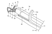
図1〜3は本発明の第1の実施の形態として自動車のフロントドアに装着されるドアウェザーストリップを示す図であって、そのうち図1はドアウェザーストリップ全体の概略を示す側面図、図2は図1に示すドアウェザーストリップ1のうち後述する上側一般部1aとフロントコーナー部1cの接続部近傍を拡大した斜視図、図3は図2におけるA−A断面図である。   1 to 3 are views showing a door weather strip mounted on a front door of an automobile as a first embodiment of the present invention, in which FIG. 1 is a side view showing an outline of the whole door weather strip, FIG. FIG. 3 is an enlarged perspective view of the vicinity of a connecting portion between an upper general portion 1a and a front corner portion 1c, which will be described later, in the door weather strip 1 shown in FIG. 1, and FIG. 3 is a cross-sectional view taken along line AA in FIG.

図1に示すように、ドアウェザーストリップ1は閉ループ状に形成され、図示外のフロントドアの外周縁部に装着されることになる。詳しくは、ドアウェザーストリップ1のうち上辺を構成する上側一般部1aと、ドアウェザーストリップ1のうち前後の縦辺および下辺を構成する側面視略コ字状の下側一般部1bとを、フロントコーナー部1cおよびリアコーナー部1dをもってそれぞれ接続している。両一般部1a,1bは、周知の押出成形法によってその断面形状が長手方向でほぼ一定のものとしてそれぞれ成形されている一方、両コーナー部1c,1dは図示外の金型をもって両一般部1a,1b同士を滑らかに連続させるように型成形されている。   As shown in FIG. 1, the door weather strip 1 is formed in a closed loop shape and is attached to an outer peripheral edge portion of a front door (not shown). Specifically, the upper general portion 1a that constitutes the upper side of the door weather strip 1 and the lower general portion 1b that is substantially U-shaped in a side view and that constitutes the front and rear vertical sides and the lower side of the door weather strip 1, The corner portion 1c and the rear corner portion 1d are connected to each other. The two general portions 1a and 1b are formed by a well-known extrusion method so that the cross-sectional shape thereof is substantially constant in the longitudinal direction, while the two corner portions 1c and 1d have molds (not shown) and the two general portions 1a. , 1b are molded so as to be smoothly continuous.

図1のほか図2,3に示すように、ドアウェザーストリップ1のうちフロントコーナー部1cと上側一般部1aとの接合部近傍においては、フロントコーナー部1cが上側一般部1aと略同一の断面形状を呈している。なお、図2では、上側一般部1aとフロントコーナー部1cとの接合部を符号Cで示している。   As shown in FIGS. 2 and 3 in addition to FIG. 1, in the door weather strip 1, in the vicinity of the joint portion between the front corner portion 1 c and the upper general portion 1 a, the front corner portion 1 c has substantially the same cross section as the upper general portion 1 a. It has a shape. In FIG. 2, a joint portion between the upper general portion 1 a and the front corner portion 1 c is indicated by a symbol C.

具体的には、フロントコーナー部1cと上側一般部1aは、長手方向に延びる空隙部3a,3bを有する断面略中空三角形状の取付基部2と、その取付基部2からそれぞれ突設された第1シール部たる中空状のメインシールリップ4および舌片状のサブシールリップ5と、上記取付基部2から反メインシールリップ4側に突設された舌片状のパネルシールリップ6と、をそれぞれ備えている点で共通している。また、取付基部2の底面のうち幅方向両端部には、当該取付基部2の長手方向に延びるインナ側突条部2aおよびアウタ側突条部2bがそれぞれ突設されているとともに、取付基部2の底面のうち幅方向中間部には、当該取付基部2の長手方向に延びる中間突条部2cが突設されている。   Specifically, the front corner portion 1c and the upper general portion 1a are respectively provided with a mounting base 2 having a substantially hollow triangular shape having gaps 3a and 3b extending in the longitudinal direction, and a first protruding from the mounting base 2 respectively. A hollow main seal lip 4 and a tongue-like sub-seal lip 5 as seal parts, and a tongue-like panel seal lip 6 projecting from the mounting base 2 to the side opposite to the main seal lip 4 are provided. In common. Further, an inner side ridge portion 2 a and an outer side ridge portion 2 b extending in the longitudinal direction of the attachment base portion 2 are respectively provided on both end portions in the width direction of the bottom surface of the attachment base portion 2. An intermediate ridge 2c extending in the longitudinal direction of the mounting base 2 protrudes from the bottom in the width direction.

ここで、上側一般部1aにおいては、サブシールリップ5とパネルシールリップ6および取付基部2が、比較的硬質なスポンジ状を呈する例えばEPDM等のゴム材料をもってそれぞれ形成されており、それよりも軟質なスポンジ状のゴム材料をもってメインシールリップ4が形成されている。   Here, in the upper general portion 1a, the sub seal lip 5, the panel seal lip 6 and the mounting base portion 2 are each formed of a rubber material such as EPDM having a relatively hard sponge shape, which is softer than that. The main seal lip 4 is formed of a sponge-like rubber material.

また、上側一般部1aは、その長手方向に沿って形成された第2シール部としてのシールビード10が取付基部2の底面から突設されている点でフロントコーナー部1cと相違している。つまり、シールビード10はドアウェザーストリップ1のうち上側一般部1aのみに形成しているものであって、フロントコーナー部1cのほかリアコーナー部1dおよび下側一般部1bにはシールビード10を形成していない。   Further, the upper general portion 1a is different from the front corner portion 1c in that a seal bead 10 as a second seal portion formed along the longitudinal direction thereof is projected from the bottom surface of the mounting base portion 2. That is, the seal bead 10 is formed only in the upper general portion 1a of the door weather strip 1, and the seal bead 10 is formed in the rear corner portion 1d and the lower general portion 1b in addition to the front corner portion 1c. Not done.

シールビード10は、取付基部2のうちアウタ側突条部2bと中間突条部2cの間に、各突条部2a〜2cよりも肉厚に形成されており、上述したメインシールリップ4よりもさらに軟質な超軟質材をもって形成されている。具体的には、メインシールリップ4よりも高発泡なスポンジ状のEPDMをもってシールビード10を形成し、その比重は例えば0.2〜0.3に設定するとよい。   The seal bead 10 is formed to be thicker than the protrusions 2a to 2c between the outer protrusion 2b and the intermediate protrusion 2c of the mounting base 2, and from the main seal lip 4 described above. Furthermore, it is formed with a soft super soft material. Specifically, the seal bead 10 is formed of a spongy EPDM having a foam higher than that of the main seal lip 4, and the specific gravity thereof may be set to 0.2 to 0.3, for example.

一方、フロントドア側のウインドウフレーム7は、周知のようにドアアウタパネルとドアインナパネルとをヘミング結合することで構成されており、そのウインドウフレーム7のうち少なくとも上辺部分には、上向きの着座面8aとその着座面8aからフランジ状に立ち上がった側壁面8bとからなる断面略L字状の取付面8がウェザーストリップ取付部として形成されている。そして、ウインドウフレーム7の着座面8aに取付基部2の各突条部2a〜2cを着座させ、その取付基部2を図示外のクリップによってウインドウフレーム7に固定することになる。   On the other hand, the window frame 7 on the front door side is configured by hemming the door outer panel and the door inner panel as is well known, and at least an upper side portion of the window frame 7 has an upward seating surface 8a. A mounting surface 8 having a substantially L-shaped cross section is formed as a weatherstrip mounting portion, and a side wall surface 8b rising from the seating surface 8a in a flange shape. Then, the protrusions 2a to 2c of the mounting base 2 are seated on the seating surface 8a of the window frame 7, and the mounting base 2 is fixed to the window frame 7 by a clip (not shown).

そして、この装着状態において上側一般部1aでは、パネルシールリップ6がウインドウフレーム7の側壁面8bに弾接するとともに、シールビード10がウインドウフレーム7の底壁面8aに弾接し、取付基部2と取付面8との間がいわゆる二重シール構造をもってシールされることになる。また、ドア閉時においては、メインシールリップ4およびサブシールリップ5のそれぞれが相手側部材たる車体パネル9のうちドア開口部の外周縁部に弾接し、いわゆる二重シール構造をもって車室内外がシールされることになる。   In this mounted state, in the upper general portion 1a, the panel seal lip 6 is in elastic contact with the side wall surface 8b of the window frame 7, and the seal bead 10 is in elastic contact with the bottom wall surface 8a of the window frame 7, so 8 is sealed with a so-called double seal structure. When the door is closed, each of the main seal lip 4 and the sub seal lip 5 is in elastic contact with the outer peripheral edge of the door opening of the vehicle body panel 9 which is a counterpart member, and has a so-called double seal structure so that the inside and outside of the vehicle interior It will be sealed.

さらに、シールビード10は、取付基部2と一体に形成され、且つその取付基部2から分離可能な略チャンネル状のカバー部たるビードカバー11によって覆われている。このビードカバー11は、取付基部2と同様のスポンジゴムをもって形成されており、そのビードカバー11のうち両側壁部11a,11bの先端が破断容易部たる薄肉部11cをもって取付基部2に接続されている。   Further, the seal bead 10 is formed integrally with the mounting base 2 and is covered with a bead cover 11 that is a substantially channel-shaped cover part that can be separated from the mounting base 2. This bead cover 11 is formed with the same sponge rubber as the mounting base 2, and the tips of the side wall portions 11 a and 11 b of the bead cover 11 are connected to the mounting base 2 with thin portions 11 c that are easily breakable portions. Yes.

より具体的には、ビードカバー11のうちアウタ側の側壁部11aの先端が、取付基部2のうちパネルシールリップ6側の側壁面に接続されている一方、ビードカバー11のうちインナ側の側壁部11bの先端が、取付基部2の底面のうちシールビード10と中間突条部2cとの間の部分に接続されており、そのビードカバー11と取付基部2との間に形成された閉断面形状の収容空間12にシールビード10が受容されている。さらに、ビードカバー11のうちフロントコーナー部1cに近い部分は、取付基部2から予め剥離した把手部たる剥離部11dとなっている。   More specifically, the tip of the outer side wall portion 11a of the bead cover 11 is connected to the side wall surface of the mounting base 2 on the panel seal lip 6 side, while the inner side wall of the bead cover 11 is connected. The tip of the portion 11b is connected to the portion of the bottom surface of the mounting base 2 between the seal bead 10 and the intermediate protrusion 2c, and is a closed cross section formed between the bead cover 11 and the mounting base 2 A seal bead 10 is received in the housing space 12 having a shape. Further, a portion of the bead cover 11 that is close to the front corner portion 1 c is a peeling portion 11 d that is a handle portion that has been peeled from the mounting base 2 in advance.

なお、上述したように、サブシールリップ5、パネルシールリップ6、取付基部2およびビードカバー11が比較的硬質なスポンジゴムをもって形成されている一方、メインシールリップ4がそれよりも軟質なスポンジゴムをもって形成され、さらに、シールビード10がメインシールリップ4よりもより一層軟質な高発泡スポンジゴムをもって形成されており、上側一般部1aは発泡の程度が互いに異なる3種類の材質から構成されているが、上側一般部1aはいわゆる三重押し出しをもって各部一体で且つ同時に成形されている。   As described above, the sub seal lip 5, the panel seal lip 6, the mounting base 2 and the bead cover 11 are formed of relatively hard sponge rubber, while the main seal lip 4 is softer than that. Furthermore, the seal bead 10 is made of a highly foamed sponge rubber that is softer than the main seal lip 4, and the upper general portion 1a is made of three types of materials having different degrees of foaming. However, the upper general portion 1a is integrally formed at the same time with so-called triple extrusion.

そして、以上のように構成したドアウェザーストリップ1では、当該ドアウェザーストリップ1の装着作業時にビードカバー11を取付基部2から分離することで、シールビード10を底壁面8aに弾接させることになる。具体的には、図4に示すように、パネルシールリップ6と側壁面8bとの間から剥離部11dを外部に引き出した状態で、取付基部2を底壁面8aに着座させて図示外のクリップによって取付基部2をウインドウフレーム7に固定する。その上で、ビードカバー11の剥離部11dを図4の矢印B方向に引っ張ることにより、ビードカバー11の薄肉部11cをその長手方向に向かって破断し、ビードカバー11をパネルシールリップ6と側壁面8bとの間から引き抜くことになる。このように、ビードカバー11を取付基部2から分離して取り除くことにより、シールビード10が底壁面8aに弾接し、所期のシール性が確保される。なお、取付基部2からビードカバー11を分離すると、薄肉部11cに沿ってばりが発生することもあるが、そのばりは外部に露出しないため外観品質に影響することはない。   And in the door weather strip 1 comprised as mentioned above, the seal bead 10 is made to elastically contact the bottom wall surface 8a by isolate | separating the bead cover 11 from the attachment base part 2 at the time of the mounting | wearing operation | work of the said door weather strip 1. FIG. . Specifically, as shown in FIG. 4, in a state where the peeling portion 11d is pulled out from between the panel seal lip 6 and the side wall surface 8b, the mounting base portion 2 is seated on the bottom wall surface 8a and a clip (not shown). To fix the mounting base 2 to the window frame 7. Then, by pulling the peeling portion 11d of the bead cover 11 in the direction of arrow B in FIG. 4, the thin portion 11c of the bead cover 11 is broken in the longitudinal direction, and the bead cover 11 is separated from the panel seal lip 6 side. It will be pulled out from between the wall surface 8b. In this way, by removing the bead cover 11 from the mounting base 2 and removing it, the seal bead 10 is brought into elastic contact with the bottom wall surface 8a, and the desired sealing performance is ensured. Note that when the bead cover 11 is separated from the mounting base portion 2, flash may occur along the thin wall portion 11 c, but since the flash is not exposed to the outside, the appearance quality is not affected.

したがって、本実施の形態によれば、超軟質材をもって形成されたシールビード10がウインドウフレーム7に装着されるまでの間ビードカバー11によって覆われているため、ドアウェザーストリップ1の保管時および輸送時に、多数のウェザーストリップ1を輸送箱もしくは保管箱に収容した場合であっても、シールビード10が他のウェザーストリップや輸送箱もしくは保管箱に押し潰されて変形したり損傷したりすることを防止でき、装着状態で確実に所期のシール性を確保できるようになる。   Therefore, according to the present embodiment, the seal bead 10 formed of an ultra-soft material is covered with the bead cover 11 until it is attached to the window frame 7, so that the door weather strip 1 is stored and transported. Sometimes, even when a large number of weather strips 1 are accommodated in a transport box or storage box, the seal beads 10 are crushed by other weather strips, transport boxes or storage boxes, and are deformed or damaged. It is possible to prevent this, and it is possible to ensure the desired sealing performance in the mounted state.

また、ビードカバー11の一部を予め取付基部2から剥離しておくことにより、その剥離部11dを引っ張ることでビードカバー11を容易に取り除くことができるようになるため、ドアウェザーストリップ1の取付作業性が良好になるメリットがある。なお、このようにビードカバー11の一部を剥離するのに代えて、例えばビードカバー11と同様のスポンジゴムをもって形成した把手部を、上側一般部1aの押出成形後の工程でビードカバー11の端部に接着固定してもよい。この場合においても同様のメリットが得られる。   Further, by removing a part of the bead cover 11 from the mounting base 2 in advance, the bead cover 11 can be easily removed by pulling the peeling part 11d. There is an advantage that workability is improved. Instead of peeling a part of the bead cover 11 in this way, for example, a handle part formed of sponge rubber similar to the bead cover 11 is formed on the bead cover 11 in a step after the extrusion of the upper general part 1a. You may adhere and fix to an edge part. In this case, the same merit can be obtained.

さらに、取付基部2をウインドウフレーム7に固定した後にビードカバー11を取り除くことで、シールビード10が着座面8aに接触するようになっているため、装着状態でシールビード10が捲れ込むことなく正規の姿勢で着座面8aに弾接するようになり、より確実に所期のシール性を確保できるようになる。   Furthermore, since the bead cover 11 is removed after the mounting base 2 is fixed to the window frame 7, the seal bead 10 comes into contact with the seating surface 8a. With this posture, it comes into elastic contact with the seating surface 8a, and the desired sealing performance can be ensured more reliably.

なお、本実施の形態では、ビードカバー11を例えばEPDM等のゴム材料によって形成するものとしたが、そのビードカバー11を熱可塑性エラストマーによって形成することも可能である。この場合には、取付基部2から分離したビードカバー11のリサイクルが可能となるメリットがある。   In the present embodiment, the bead cover 11 is formed of a rubber material such as EPDM. However, the bead cover 11 may be formed of a thermoplastic elastomer. In this case, there is an advantage that the bead cover 11 separated from the mounting base 2 can be recycled.

また、本実施の形態では、取付基部2の底面に形成したシールビード10の材質を超軟質材としたが、このシールビード10に代えて粘着性材料からなるシールビードを採用することも可能である。具体的には、例えばロジン樹脂やフェノール樹脂、石油樹脂などの粘着付与材をEPDMに添加した粘着性ゴムをもってシールビードを形成するとよい。この場合には、ビードカバー11により、保管時または輸送時におけるシールビードへの塵埃の付着を防止し、そのシールビードが正規の粘着性を保ったままドアウェザーストリップをウインドウフレームに装着できるようになるから、上述した第1の実施の形態と同様に確実に所期のシール性を確保できるようになるメリットがある。   In this embodiment, the material of the seal bead 10 formed on the bottom surface of the mounting base 2 is an ultra-soft material. However, a seal bead made of an adhesive material can be used instead of the seal bead 10. is there. Specifically, for example, the seal bead may be formed of an adhesive rubber obtained by adding a tackifier such as rosin resin, phenol resin, or petroleum resin to EPDM. In this case, the bead cover 11 prevents dust from adhering to the seal bead during storage or transportation so that the door weather strip can be attached to the window frame while maintaining its normal adhesiveness. Therefore, there is an advantage that the desired sealing property can be surely secured as in the first embodiment described above.

図5は、上述した第1の実施の形態におけるビードカバー11の変形例を示す図である。図5に示す変形例では、シールビード10の左右両側にそれぞれ壁体状のビードカバー13,14をカバー部として設けたものであって、これら両ビードカバー13,14をもってシールビード10を左右両側から覆っている。換言すれば、両シールビード13,14間に形成された溝状空間15にシールビード10が受容されるようになっている。なお、両ビードカバー13,14が破断容易部としての薄肉部13a,14aをもって取付基部2に接続されていることは上述した第1の実施の形態と同様である。   FIG. 5 is a view showing a modification of the bead cover 11 in the first embodiment described above. In the modification shown in FIG. 5, wall-like bead covers 13 and 14 are provided as cover portions on the left and right sides of the seal bead 10, respectively. Covering from. In other words, the seal bead 10 is received in the groove-like space 15 formed between the seal beads 13 and 14. In addition, it is the same as that of 1st Embodiment mentioned above that both bead covers 13 and 14 are connected to the attachment base 2 with the thin parts 13a and 14a as an easily breakable part.

したがって、本変形例では、上述した第1の実施の形態と同様に、ドアウェザーストリップ1の装着時に両ビードカバー13,14を取り除くことで、シールビード10を底壁面8aに弾接させることになり、この変形例においても上述した第1の実施の形態と略同様の効果が得られる。なお、図示は省略しているが、本変形例のようにビードカバーを複数設ける場合には、各ビードカバーを取付基部から分離する際の作業性を考慮すると、各ビードカバーの端部同士を例えばクリップ等で一つに束ねておくとよい。   Therefore, in this modification, as in the first embodiment described above, by removing both bead covers 13 and 14 when the door weather strip 1 is mounted, the seal bead 10 is elastically brought into contact with the bottom wall surface 8a. Thus, also in this modified example, substantially the same effect as that of the first embodiment described above can be obtained. Although not shown in the drawings, in the case where a plurality of bead covers are provided as in this modification, considering the workability when separating each bead cover from the mounting base, the ends of each bead cover are connected to each other. For example, it may be bundled together with a clip or the like.

図6は上述した第1の実施の形態の別の変形例を示す図である。この図6に示す変形例は、第1の実施の形態におけるシールビード10に代え、取付基部2のうちパネルシールリップ6側の側面に第2シール部たるボトムリップ16を設けたものであって、このボトムリップ16がカバー部としてのリップカバー17をもって覆われている。他の部分は上述した第1の実施の形態と同様である。なお、リップカバー17は、取付基部2と同様に比較的硬質なスポンジゴムをもって形成されている一方、ボトムリップ16は、第1の実施の形態におけるシールビード10と同様に超軟質材をもって形成されている。   FIG. 6 is a diagram showing another modification of the above-described first embodiment. In the modified example shown in FIG. 6, instead of the seal bead 10 in the first embodiment, a bottom lip 16 as a second seal portion is provided on the side surface of the mounting base 2 on the panel seal lip 6 side. The bottom lip 16 is covered with a lip cover 17 as a cover portion. Other parts are the same as those in the first embodiment. The lip cover 17 is formed of a relatively hard sponge rubber like the mounting base 2, while the bottom lip 16 is formed of an ultra-soft material like the seal bead 10 in the first embodiment. ing.

詳細には、リップカバー17のうちアウタ側の側壁部17aが破断容易部としての薄肉部17cをもってパネルリップ6の根元部に接続されている一方、リップカバー17のうちインナ側の側壁部17bは、取付基部2の底壁のうちアウタ側突条部2bと中間突条部2cの間の部分に破断容易部としての薄肉部17cをもって接続されている。そして、リップカバー17と取付基部2との間に形成された閉断面形状の収容空間18にボトムリップ16が受容されている。   Specifically, the outer side wall portion 17a of the lip cover 17 is connected to the base portion of the panel lip 6 with a thin portion 17c as an easily breakable portion, while the inner side wall portion 17b of the lip cover 17 is The bottom wall of the mounting base 2 is connected to a portion between the outer ridge 2b and the intermediate ridge 2c with a thin portion 17c as an easily breakable portion. Then, the bottom lip 16 is received in the closed space 18 having a closed cross section formed between the lip cover 17 and the mounting base 2.

したがって、本変形例では、上述した第1の実施の形態と同様に、ドアウェザーストリップ1の装着時にリップカバー17を取り除き、ボトムリップ17が底壁面8aに弾接させることになる。したがって、本変形例においても上述した第1の実施の形態と略同様の効果が得られる。   Therefore, in this modification, as in the first embodiment described above, the lip cover 17 is removed when the door weather strip 1 is mounted, and the bottom lip 17 is brought into elastic contact with the bottom wall surface 8a. Therefore, also in this modification, substantially the same effect as that of the first embodiment described above can be obtained.

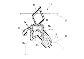
図7は本実施の形態の第2の実施の形態としてトランクウェザーストリップを示す断面図である。   FIG. 7 is a sectional view showing a trunk weather strip as a second embodiment of the present embodiment.

図7に示すトランクウェザーストリップ19は、長手方向で均一な断面形状に押出成形されたものであって、略チャンネル状の取付基部たるウエルト部20と、そのウエルト部20から上方に突出する第1シール部たる中空状のメインシールリップ21と、ウエルト部20のうち一方の側壁の根元部から外向きに突設された舌片状のサブシールリップ22と、ウエルト部20のうち他方の側壁の先端部から外向きに突設された第2シール部たる舌片状のボディシールリップ23と、ウエルト部20の両側壁からそれぞれ内向きに突設された複数の係止リップ24と、ボディシールリップ23を覆う断面略U字状のリップカバー25と、を有している。なお、リップカバー25が破断容易部としての薄肉部25aをもってウエルト部20に接続されていることは上述した第1の実施の形態と同様である。   The trunk weatherstrip 19 shown in FIG. 7 is extruded in a uniform cross-sectional shape in the longitudinal direction, and includes a welt portion 20 that is a substantially channel-shaped attachment base, and a first protruding upward from the welt portion 20. A hollow main seal lip 21 as a seal portion, a tongue-like sub seal lip 22 projecting outward from a root portion of one side wall of the welt portion 20, and the other side wall of the welt portion 20 A tongue-shaped body seal lip 23 as a second seal portion projecting outward from the tip portion, a plurality of locking lips 24 projecting inward from both side walls of the welt portion 20, and a body seal And a lip cover 25 having a substantially U-shaped cross section covering the lip 23. It is to be noted that the lip cover 25 is connected to the welt portion 20 with a thin portion 25a as an easily breakable portion as in the first embodiment described above.

ウエルト部20は、例えばEPDMからなる硬質なソリッドゴムをもって形成され、内部に略チャンネル状の芯材20aが埋設されている。また、サブシールリップ22の根元部と各係止リップ24およびリップカバー25は、ウエルト部20と同様のソリッドゴムをもってそれぞれ形成され、サブシールリップ22の先端部およびメインシールリップ21は例えばEPDMからなる比較的軟質なスポンジゴムをもって形成されている。さらに、そのスポンジゴムよりも軟質な超軟質材をもってボディシールリップ23が形成されている。なお、このボディシールリップ23としてより具体的には、第1の実施の形態におけるシールビード10と同様の材料を用いるとよい。   The welt portion 20 is formed of a hard solid rubber made of, for example, EPDM, and a substantially channel-shaped core material 20a is embedded therein. Further, the base portion of the sub seal lip 22 and the locking lips 24 and the lip cover 25 are respectively formed of the same solid rubber as the welt portion 20, and the tip portion of the sub seal lip 22 and the main seal lip 21 are made of, for example, EPDM. It is formed with a relatively soft sponge rubber. Further, the body seal lip 23 is formed of a super soft material softer than the sponge rubber. More specifically, the body seal lip 23 may be made of the same material as the seal bead 10 in the first embodiment.

以上のように構成したトランクウェザーストリップ19は、ウェザーストリップ取付部たる車体パネル26のうちトランク開口部の開口縁部に形成されたフランジ部26aにウエルト部20を嵌合させることで車体パネル26に装着される。そして、この状態でリップカバー25を取り除くことによってボディシールリップ23が車体パネル26に弾接し、ウエルト部20と車体パネル26との間をシールすることになる。また、メインシールリップ21は、トランク閉時に相手側部材たるトランクリッド27に弾接することでウエルト部20とトランクリッド27との間をシールすることになる。したがって、本実施の形態においても上述した第1の実施の形態と略同様の効果が得られる。   The trunk weather strip 19 configured as described above is fitted to the vehicle body panel 26 by fitting the welt portion 20 to the flange portion 26a formed at the opening edge of the trunk opening portion of the vehicle body panel 26 which is the weather strip mounting portion. Installed. Then, by removing the lip cover 25 in this state, the body seal lip 23 comes into elastic contact with the vehicle body panel 26 and seals between the welt portion 20 and the vehicle body panel 26. Further, the main seal lip 21 seals between the welt portion 20 and the trunk lid 27 by elastically contacting the trunk lid 27 as a counterpart member when the trunk is closed. Therefore, also in this embodiment, substantially the same effect as that of the first embodiment described above can be obtained.

1…ウェザーストリップ
2…取付基部
4…メインシールリップ(第1シール部)
8…取付面(ウェザーストリップ取付部)
9…車体パネル(相手側部材)
10…シールビード(第2シール部)
11…ビードカバー(カバー部)
11c…薄肉部(破断容易部)
11d…剥離部(把手部)
12…収容空間
13…ビードカバー(カバー部)
13a…薄肉部(破断容易部)
14…ビードカバー(カバー部)
14a…薄肉部
16…ボトムリップ(第2シール部)
17…リップカバー(カバー部)
17c…薄肉部(破断容易部)
18…収容空間
19…トランクウェザーストリップ
20…ウエルト部(取付基部)
21…メインシールリップ(第1シール部)
23…ボディシールリップ(第2シール部)
25…リップカバー(カバー部)
25a…薄肉部(破断容易部)
26…車体パネル(ウェザーストリップ取付部)
27…トランクリッド(相手側部材)
DESCRIPTION OF SYMBOLS 1 ... Weather strip 2 ... Mounting base 4 ... Main seal lip (1st seal part)
8 ... Mounting surface (weather strip mounting part)
9 ... Body panel (mating member)
10: Seal bead (second seal part)
11 ... Bead cover (cover part)
11c Thin portion (easy to break)
11d ... peeling part (grip part)
12 ... Storage space 13 ... Bead cover (cover part)
13a: Thin part (easy to break)
14 ... Bead cover (cover part)
14a ... Thin part 16 ... Bottom lip (second seal part)
17 ... Lip cover (cover part)
17c ... Thin-walled portion (easy to break)
18 ... Storage space 19 ... Trunk weather strip 20 ... Welt part (mounting base)
21 ... Main seal lip (first seal part)
23 ... Body seal lip (second seal part)
25 ... Lip cover (cover part)
25a ... Thin portion (easy to break)
26 ... Body panel (weather strip mounting part)
27 ... Trunk lid (other member)

Claims (5)

自動車のウェザーストリップ取付部に固定される取付基部を中心として構成されていて、その取付基部から突設された第1シール部が自動車の相手側部材に弾接する一方、上記取付基部から突設され、上記第1シール部よりも軟質または粘着性のある第2シール部が上記ウェザーストリップ取付部に弾接することにより、上記ウェザーストリップ取付部と相手側部材との間をシールするウェザーストリップにおいて、
上記第2シール部が、上記取付基部と一体に形成されたカバー部をもって覆われているとともに、そのカバー部のうち取付基部に対する根元部分に薄肉状の破断容易部が形成されていて、その破断容易部の破断によってカバー部を取付基部から分離可能になっていることを特徴とするウェザーストリップ。
The first seal portion protruding from the mounting base is elastically contacted with a counterpart member of the vehicle, and protrudes from the mounting base. In the weather strip that seals between the weather strip mounting portion and the counterpart member by the second seal portion being softer or sticker than the first seal portion elastically contacting the weather strip mounting portion,
The second seal portion is covered with a cover portion formed integrally with the mounting base portion, and a thin-walled easily breakable portion is formed at the root portion of the cover portion with respect to the mounting base portion, A weather strip characterized in that the cover portion can be separated from the mounting base portion by breaking the easy portion.
上記カバー部は、上記取付基部の外壁面との間に閉断面形状の収容空間を隔成する溝形を呈していて、上記収容空間に上記第2シール部が受容されていることを特徴とする請求項1に記載のウェザーストリップ。   The cover portion has a groove shape that divides a housing space having a closed cross-sectional shape with an outer wall surface of the mounting base portion, and the second seal portion is received in the housing space. The weather strip according to claim 1. 上記カバー部は、上記第2シール部を側方から覆う壁体状に形成されていることを特徴とする請求項1に記載のウェザーストリップ。   The weather strip according to claim 1, wherein the cover part is formed in a wall shape covering the second seal part from the side. 上記取付基部のうち長手方向における所定の領域に上記第2シール部およびカバー部がそれぞれ形成されていて、上記カバー部の長手方向一端部に当該カバー部を取付基部から分離するための把手部が形成されていることを特徴とする請求項1〜3のいずれかに記載のウェザーストリップ。   The second seal part and the cover part are respectively formed in a predetermined region in the longitudinal direction of the attachment base part, and a handle part for separating the cover part from the attachment base part at one longitudinal end part of the cover part. The weather strip according to claim 1, wherein the weather strip is formed. 上記カバー部の長手方向一端部が上記取付基部から予め剥離していて、その剥離部を把手部として上記カバー部を取付基部から分離可能になっていることを特徴とする請求項4に記載のウェザーストリップ。   The longitudinal direction one end part of the said cover part has peeled previously from the said attachment base, The said cover part can be isolate | separated from the attachment base by using the peeling part as a handle part. Weather Strip.
JP2009048745A 2009-03-03 2009-03-03 Weather Strip Expired - Fee Related JP5276477B2 (en)

Priority Applications (1)

Application Number Priority Date Filing Date Title
JP2009048745A JP5276477B2 (en) 2009-03-03 2009-03-03 Weather Strip

Applications Claiming Priority (1)

Application Number Priority Date Filing Date Title
JP2009048745A JP5276477B2 (en) 2009-03-03 2009-03-03 Weather Strip

Publications (2)

Publication Number Publication Date
JP2010202019A true JP2010202019A (en) 2010-09-16
JP5276477B2 JP5276477B2 (en) 2013-08-28

Family

ID=42963942

Family Applications (1)

Application Number Title Priority Date Filing Date
JP2009048745A Expired - Fee Related JP5276477B2 (en) 2009-03-03 2009-03-03 Weather Strip

Country Status (1)

Country Link
JP (1) JP5276477B2 (en)

Families Citing this family (1)

* Cited by examiner, † Cited by third party
Publication number Priority date Publication date Assignee Title
CN103625258B (en) * 2013-12-10 2016-02-03 重庆长安汽车股份有限公司 A kind of car door sealing strip connect corner structure

Citations (5)

* Cited by examiner, † Cited by third party
Publication number Priority date Publication date Assignee Title
JPH0357739A (en) * 1989-07-25 1991-03-13 Toyoda Gosei Co Ltd Connection of weatherstrip
JPH05238328A (en) * 1992-03-02 1993-09-17 Toyoda Gosei Co Ltd Weather strip for automobile
JPH0776249A (en) * 1993-02-24 1995-03-20 Schlegel Uk Ltd Strip piece and its formation
JPH082346A (en) * 1994-06-22 1996-01-09 Toyoda Gosei Co Ltd Sealant for weatherstrip
JP2008279884A (en) * 2007-05-10 2008-11-20 Nishikawa Rubber Co Ltd Weather strip for automobile

Patent Citations (5)

* Cited by examiner, † Cited by third party
Publication number Priority date Publication date Assignee Title
JPH0357739A (en) * 1989-07-25 1991-03-13 Toyoda Gosei Co Ltd Connection of weatherstrip
JPH05238328A (en) * 1992-03-02 1993-09-17 Toyoda Gosei Co Ltd Weather strip for automobile
JPH0776249A (en) * 1993-02-24 1995-03-20 Schlegel Uk Ltd Strip piece and its formation
JPH082346A (en) * 1994-06-22 1996-01-09 Toyoda Gosei Co Ltd Sealant for weatherstrip
JP2008279884A (en) * 2007-05-10 2008-11-20 Nishikawa Rubber Co Ltd Weather strip for automobile

Also Published As

Publication number Publication date
JP5276477B2 (en) 2013-08-28

Similar Documents

Publication Publication Date Title
KR101706835B1 (en) Glass run channel
JP6322371B2 (en) Door weather strip
JP5229694B2 (en) Weather strip
JP5513750B2 (en) Weather strip and weather strip mounting structure
JP2003048493A (en) Weather strip
JP5556776B2 (en) Weather strip
JP2009280193A (en) Weather strip for motor vehicle
JP5276477B2 (en) Weather Strip
JP2004284582A (en) Sealing structure of vehicle panel assembly and sealing strip
JP2006182090A (en) Weather strip for automobile
JP2010137634A (en) Weather strip for automobile
JP3864335B2 (en) Automotive door weatherstrip
US20070209286A1 (en) Lip retention structure of molded part in weather-strip
JP3879420B2 (en) Weather strip and its mounting structure
JP5455744B2 (en) Weather strip
JP2006069253A (en) Trimming member and method for assembling the same
JP2009067195A (en) Door weather strip
JP2002274285A (en) Weather strip and its fitting structure
JP2004098888A (en) Weather strip mounting structure
JP2014177163A (en) Weather strip
JP5431543B2 (en) Automotive seal structure
US20050279026A1 (en) Weatherstrip for vehicles
JP2010137741A (en) Weatherstrip
JP2007168552A (en) Door weather strip
JP2010163067A (en) Weather strip for automobile

Legal Events

Date Code Title Description
A621 Written request for application examination

Free format text: JAPANESE INTERMEDIATE CODE: A621

Effective date: 20120210

A977 Report on retrieval

Free format text: JAPANESE INTERMEDIATE CODE: A971007

Effective date: 20130412

TRDD Decision of grant or rejection written
A01 Written decision to grant a patent or to grant a registration (utility model)

Free format text: JAPANESE INTERMEDIATE CODE: A01

Effective date: 20130423

A61 First payment of annual fees (during grant procedure)

Free format text: JAPANESE INTERMEDIATE CODE: A61

Effective date: 20130517

R150 Certificate of patent or registration of utility model

Free format text: JAPANESE INTERMEDIATE CODE: R150

LAPS Cancellation because of no payment of annual fees