JP2010200419A - Outer rotor type rotating electric machine - Google Patents

Outer rotor type rotating electric machine Download PDF

Info

Publication number
JP2010200419A
JP2010200419A JP2009039983A JP2009039983A JP2010200419A JP 2010200419 A JP2010200419 A JP 2010200419A JP 2009039983 A JP2009039983 A JP 2009039983A JP 2009039983 A JP2009039983 A JP 2009039983A JP 2010200419 A JP2010200419 A JP 2010200419A
Authority
JP
Japan
Prior art keywords
outer rotor
substrate
rotor type
sensor
type rotating
Prior art date
Legal status (The legal status is an assumption and is not a legal conclusion. Google has not performed a legal analysis and makes no representation as to the accuracy of the status listed.)
Pending
Application number
JP2009039983A
Other languages
Japanese (ja)
Inventor
Masami Hagimura
将巳 萩村
Takanori Matsui
孝典 松井
Hideaki Ito
秀明 伊藤
Yuko Tada
優子 多田
Current Assignee (The listed assignees may be inaccurate. Google has not performed a legal analysis and makes no representation or warranty as to the accuracy of the list.)
Mitsuba Corp
Original Assignee
Mitsuba Corp
Priority date (The priority date is an assumption and is not a legal conclusion. Google has not performed a legal analysis and makes no representation as to the accuracy of the date listed.)
Filing date
Publication date
Application filed by Mitsuba Corp filed Critical Mitsuba Corp
Priority to JP2009039983A priority Critical patent/JP2010200419A/en
Publication of JP2010200419A publication Critical patent/JP2010200419A/en
Pending legal-status Critical Current

Links

Images

Landscapes

  • Brushless Motors (AREA)

Abstract

<P>PROBLEM TO BE SOLVED: To provide an outer rotor type rotating electric machine having a detecting sensor which is easily manufactured. <P>SOLUTION: The outer rotor type rotating electric machine has a stator core made of a magnetic material, a bowl-like rotor rotating around the stator core, and a detecting sensor arranged on the stator core and detecting the rotating position of the rotor. The detecting sensor has a plurality of hall ICs for detecting a magnetic flux of the magnet, a fan-like substrate connected to the plurality of hall ICs, a lead wire connected to the substrate, and a fan-like sensor case for housing the plurality of hall ICs and the substrate. The substrate has a plurality of through holes for allowing the lead wire to be inserted therein. The sensor case has a plurality of insertion portions for allowing the lead wire to be inserted therein. The plurality of through holes are disposed so as to overlap on the plurality of insertion portions. Since the lead wire is guided by the insertion portion to the through holes formed on the substrate, the detecting sensor is easily manufactured. <P>COPYRIGHT: (C)2010,JPO&INPIT

Description

本発明は、自動二輪車のエンジン等に設けられるアウタロータ型の回転電機の技術分野に関するものである。   The present invention relates to a technical field of an outer rotor type rotating electrical machine provided in an engine or the like of a motorcycle.

一般に、自動二輪車のエンジンに設けられるアウタロータ型の回転電機は、エンジンの外壁上に固定されるステータコアと、エンジンのクランクシャフトに固定され、ステータコアの周りを回転するロータと、ステータコアに固定され、ロータの回転位置を検出する検出センサとを有している。ステータコアは、磁性材料からなる複数のコアプレートを積層形成したものであって、円環状に形成された本体部と、本体部から放射状に突出形成されたT字形状のティース部とを有しており、ステータコアのティース部には、コイルが巻装されている。ロータは、磁性材料からなる有底円筒状に形成されており、複数のマグネットを有している。検出センサは、複数のホールICと、ホールICが接続された基板とを有している。   2. Description of the Related Art Generally, an outer rotor type rotating electrical machine provided in an engine of a motorcycle is a stator core fixed on the outer wall of the engine, a rotor fixed to the crankshaft of the engine and rotating around the stator core, and a rotor fixed to the stator core. And a detection sensor for detecting the rotational position of the motor. The stator core is formed by laminating a plurality of core plates made of a magnetic material, and has a main body part formed in an annular shape and a T-shaped tooth part formed radially projecting from the main body part. A coil is wound around the teeth portion of the stator core. The rotor is formed in a bottomed cylindrical shape made of a magnetic material and has a plurality of magnets. The detection sensor has a plurality of Hall ICs and a substrate to which the Hall ICs are connected.

基板には、リード線が接続されており、リード線は制御部と電気的に接続される。したがって、ホールICと制御部は、電気的に接続される。そのため、ホールICが、ロータに配設されたマグネットの磁束の方向の切り替わりを検出すると、制御部は、信号を生成する。この信号に基づいて、制御部はエンジンを所定のタイミングで点火し、コイルに電流を供給する(例えば、特許文献1参照)。   Lead wires are connected to the substrate, and the lead wires are electrically connected to the control unit. Therefore, the Hall IC and the control unit are electrically connected. For this reason, when the Hall IC detects a change in the direction of the magnetic flux of the magnet disposed in the rotor, the control unit generates a signal. Based on this signal, the control unit ignites the engine at a predetermined timing and supplies current to the coil (see, for example, Patent Document 1).

特開2002−252946JP 2002-252946 A

ところが、前記従来のものでは、リード線は、各々、基板に形成された貫通孔に挿入される。そのため、作業者は、リード線を基板に挿入し難く、検出センサを容易に製造することができなかった。   However, in the conventional device, each lead wire is inserted into a through hole formed in the substrate. Therefore, it is difficult for an operator to insert the lead wire into the substrate, and the detection sensor cannot be easily manufactured.

そのため、容易に製造可能な検出センサが望まれており、本発明の目的は、この課題を解決する検出センサを備えたアウタロータ型の回転電機を提供することにある。   Therefore, a detection sensor that can be easily manufactured is desired, and an object of the present invention is to provide an outer rotor type rotating electrical machine including a detection sensor that solves this problem.

請求項1に記載された発明は、略T字状に形成された複数のティース部を備えた磁性材料からなるステータコアと、ステータコアのティース部に巻装されたコイルと、ステータコアの周りを回転する碗形状のロータと、ロータの内周面に磁極を交互にして配設された複数のマグネットと、ステータコア上に配置され、ロータの回転位置を検出する検出センサとを有するアウタロータ型の回転電機において、検出センサは、略扇状に形成されたセンサケースと、センサケース内に収容されるセンサユニットとを有しており、センサユニットは、マグネットの磁束の方向の切り替わりを検出する複数のホールICと、複数のホールICが取り付けられる略扇形状のベース部材と、ベース部材に固定され、複数のホールICと電気的に接続される扇形状の基板と、基板に接続されるリード線とを有しており、センサケースの内周面には、センサケースから導き出されたリード線を収束するハウジングが一体的に形成されていることを特徴とするアウタロータ型の回転電機である。   The invention described in claim 1 rotates around the stator core, a stator core made of a magnetic material having a plurality of teeth formed in a substantially T shape, a coil wound around the teeth of the stator core, and the stator core. In an outer rotor type rotating electrical machine having a hook-shaped rotor, a plurality of magnets alternately arranged with magnetic poles on the inner peripheral surface of the rotor, and a detection sensor disposed on a stator core and detecting a rotational position of the rotor The detection sensor has a sensor case formed in a substantially fan shape, and a sensor unit housed in the sensor case, and the sensor unit includes a plurality of Hall ICs that detect switching of the direction of magnetic flux of the magnet. A substantially fan-shaped base member to which a plurality of Hall ICs are attached, and a fan fixed to the base member and electrically connected to the plurality of Hall ICs And a lead wire connected to the substrate, and a housing for converging the lead wire led from the sensor case is integrally formed on the inner peripheral surface of the sensor case. This is an outer rotor type rotating electrical machine.

請求項2に記載された発明は、請求項1に記載されたアウタロータ型の回転電機において、ハウジングは、リード線が挿入される第1の開口部と、第1の開口部に挿入されたリード線が引き出される第2の開口部と、第1の開口部に挿入されたリード線を、第2の開口部に案内するガイド部とを備えたことを特徴とするアウタロータ型の回転電機である。   According to a second aspect of the present invention, in the outer rotor type rotating electric machine according to the first aspect, the housing includes a first opening into which the lead wire is inserted, and a lead inserted into the first opening. An outer rotor type rotating electrical machine comprising a second opening from which a wire is drawn out, and a guide for guiding a lead wire inserted into the first opening to the second opening. .

請求項3に記載された発明は、請求項1または請求項2に記載されたアウタロータ型の回転電機において、基板には、リード線が挿入される複数の貫通孔が形成されており、センサケースの底面には、センサケースの内周面に沿って形成された複数の突出片と、基板の複数の貫通孔に対応する位置に形成された複数の挿入部とが形成されており、リード線は、センサケースの底面に形成された挿入部を介して、複数の貫通孔に挿入され、突出片によって保持されることを特徴とするアウタロータ型の回転電機である。   According to a third aspect of the present invention, in the outer rotor type rotating electric machine according to the first or second aspect, the substrate has a plurality of through holes into which lead wires are inserted, and the sensor case A plurality of projecting pieces formed along the inner peripheral surface of the sensor case and a plurality of insertion portions formed at positions corresponding to the plurality of through holes of the substrate are formed on the bottom surface of the lead wire. Is an outer rotor type rotating electrical machine which is inserted into a plurality of through holes through an insertion portion formed on the bottom surface of the sensor case and held by a protruding piece.

請求項4に記載された発明は、請求項1から請求項3のいずれか1項に記載されたアウタロータ型の回転電機において、検出センサは、複数のホールICが取り付けられるベース部材を有しており、ベース部材は、扇形状の本体部と、本体部から突出形成された1対の第1の固定部とを有しており、基板は、ベース部材の第1の固定部によって、ベース部材の本体部に取り付けられることを特徴とするアウタロータ型の回転電機である。   According to a fourth aspect of the present invention, in the outer rotor type rotating electric machine according to any one of the first to third aspects, the detection sensor has a base member to which a plurality of Hall ICs are attached. The base member has a fan-shaped main body portion and a pair of first fixing portions protruding from the main body portion, and the substrate is formed by the first fixing portion of the base member. The outer rotor type rotating electrical machine is attached to the main body of the outer rotor.

請求項5に記載された発明は、請求項1から請求項4のいずれか1項に記載されたアウタロータ型の回転電機において、センサケースは、センサケースの底面から突出形成された第2の固定部を有しており、基板は、第2の固定部によって、センサケースに固定されることを特徴とするアウタロータ型の回転電機である。   According to a fifth aspect of the present invention, in the outer rotor type rotating electrical machine according to any one of the first to fourth aspects, the sensor case projects from the bottom surface of the sensor case. And the substrate is fixed to the sensor case by the second fixing portion.

本発明によると、リード線は、センサケースに形成された挿入部に挿入することで、基板の貫通孔に挿入される。そのため、作業者は、効率よく、リード線を基板に接続することができ、検出センサは、容易に製造される。   According to the present invention, the lead wire is inserted into the through hole of the substrate by being inserted into the insertion portion formed in the sensor case. Therefore, the operator can efficiently connect the lead wire to the substrate, and the detection sensor is easily manufactured.

本発明の実施形態における始動発電機の斜視図である。It is a perspective view of the starter generator in the embodiment of the present invention. 図1の始動発電機のA−A断面図である。It is AA sectional drawing of the starting generator of FIG. 図1の始動発電機の平面図である。It is a top view of the starter generator of FIG. 始動発電機の分解図である。It is an exploded view of a starter generator. ステータコアの斜視図である。It is a perspective view of a stator core. インシュレータの斜視図である。It is a perspective view of an insulator. ロータの内周面部の展開図である。It is an expanded view of the internal peripheral surface part of a rotor. 検出センサの背面図である。It is a rear view of a detection sensor. 検出センサの背面斜視図である。It is a back perspective view of a detection sensor. 検出センサの斜視図である。It is a perspective view of a detection sensor. 検出センサの分解斜視図である。It is a disassembled perspective view of a detection sensor. センサユニットの分解斜視図である。It is a disassembled perspective view of a sensor unit. ベース部材の背面図である。It is a rear view of a base member. センサケースの平面図である。It is a top view of a sensor case. 図14のB−B断面図である。It is BB sectional drawing of FIG. 図14のC−C断面図である。It is CC sectional drawing of FIG. 図14のD部拡大図である。It is the D section enlarged view of FIG. 図14のE部拡大図である。It is the E section enlarged view of FIG. 図18のF−F断面図である。It is FF sectional drawing of FIG. 制御部が生成する信号を示す図である。It is a figure which shows the signal which a control part produces | generates. 基板の斜視図である。It is a perspective view of a board | substrate.

次に、本発明のアウタロータ型の回転電機を、始動発電機に適用した場合について、図1から図20に基づいて説明する。   Next, the case where the outer rotor type rotating electrical machine of the present invention is applied to a starter generator will be described with reference to FIGS.

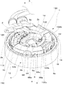
図1は、本発明の実施形態における始動発電機1の斜視図であり、図2は、図1の始動発電機1のA−A断面図、図3は、始動発電機1の正面図である。図1、図2、図3に示されるように、始動発電機1は、車両のエンジン(不図示)に固定されるステータコア2と、エンジンのクランクシャフト(不図示)に固定されるロータ4と、ロータ4の回転位置を検出する略扇形状の検出センサ6とを有している。   1 is a perspective view of a starter generator 1 according to an embodiment of the present invention, FIG. 2 is a cross-sectional view of the starter generator 1 of FIG. 1 taken along line AA, and FIG. 3 is a front view of the starter generator 1. is there. As shown in FIGS. 1, 2, and 3, the starter generator 1 includes a stator core 2 fixed to a vehicle engine (not shown), and a rotor 4 fixed to an engine crankshaft (not shown). And a substantially fan-shaped detection sensor 6 for detecting the rotational position of the rotor 4.

ステータコア2は、磁性材料からなる複数のコアプレートを積層し形成されたものであって、円環状に形成された本体部2aと、T字状に形成された18個のティース部2bを有しており、ティース部2bには、インシュレータ110が装着されている。また、ティース部2bには、インシュレータ110を介して、コイル10が巻装されている。   The stator core 2 is formed by laminating a plurality of core plates made of a magnetic material, and has a main body portion 2a formed in an annular shape and 18 teeth portions 2b formed in a T shape. An insulator 110 is attached to the tooth portion 2b. Further, the coil 10 is wound around the tooth portion 2b via an insulator 110.

エンジンのクランクシャフトに固定されるロータ4は、磁性材料からなる碗形状のヨーク12と、ヨーク12の底面部12aに固定されたボス部14とを有しており、ロータ4の内周面部4aには、12個のマグネット16が磁極を交互にして配設されている。   The rotor 4 fixed to the crankshaft of the engine has a bowl-shaped yoke 12 made of a magnetic material, and a boss portion 14 fixed to the bottom surface portion 12 a of the yoke 12, and the inner peripheral surface portion 4 a of the rotor 4. The 12 magnets 16 are arranged with alternating magnetic poles.

不図示の制御部は、ステータコア2に巻装されたコイル10に電流を供給し、ロータ4を回転させる。ロータ4は、不図示のエンジンのクランクシャフトに連結されているため、ロータ4が回転すると、ロータ4に連結されたエンジンのクランクシャフトは回転し、エンジンは、始動される。   A control unit (not shown) supplies current to the coil 10 wound around the stator core 2 to rotate the rotor 4. Since the rotor 4 is connected to a crankshaft of an engine (not shown), when the rotor 4 rotates, the crankshaft of the engine connected to the rotor 4 rotates and the engine is started.

エンジンの始動後、ロータ4がエンジンの回転に伴ってステータコア2の周りを回転すると、ステータコア2に巻装されたコイル10には、誘導起電力が生じる。なお、マグネット16は、マグネットカバー18によって保護されており、マグネットカバー18は、ロータ4の底面部4bに形成されたエンボス4dによってカシメ固定されている。   When the rotor 4 rotates around the stator core 2 as the engine rotates after the engine starts, an induced electromotive force is generated in the coil 10 wound around the stator core 2. The magnet 16 is protected by a magnet cover 18, and the magnet cover 18 is caulked and fixed by an emboss 4 d formed on the bottom surface portion 4 b of the rotor 4.

検出センサ6は、検出センサ6の内周面部6aから突出形成された支持部62と、検出センサ6の外周面部6bから突出形成された支持部64とを有している。支持部62は、不図示の螺子等によって、ステータコア2の本体部2aに固定され、支持部64は、不図示のボルト等によって、車両のエンジンに固定される。すなわち、検出センサ6は、支持部62を介してステータコア2の本体部2aに固定され、支持部64を介して車両のエンジンに固定される。   The detection sensor 6 has a support portion 62 that protrudes from the inner peripheral surface portion 6 a of the detection sensor 6 and a support portion 64 that protrudes from the outer peripheral surface portion 6 b of the detection sensor 6. The support portion 62 is fixed to the main body portion 2a of the stator core 2 by a screw (not shown) or the like, and the support portion 64 is fixed to the vehicle engine by a bolt (not shown) or the like. That is, the detection sensor 6 is fixed to the main body 2 a of the stator core 2 via the support portion 62, and is fixed to the vehicle engine via the support portion 64.

検出センサ6は、検出センサ6の外側の底面部6dに突出形成された脚部80a、80b、80c、80dを有し、脚部80a、80b、80c、80dは、各々、ホールIC50a、50b、50c、50dを収容する。脚部80a、80b、80c、80dは、各々、ステータコア2のティース部2bの間に配され、ロータ4の内周面部4aに対向して配置される。なお、ホールIC50a、50b、50c、50dは、検出センサ6に注入された充填材150によって保護されている。ロータ4がステータコア2の周りを回転すると、各ホールIC50a、50b、50c、50dは、マグネット16から生じる磁束の方向の切り替わりを検出し、検出センサ6は、ロータ4の回転位置を検出する。ホールIC50a、50b、50c、50dは、ロータ4の内周面部4aに配設されたマグネット16の磁界そのものを検出するため、検出センサ6は、ロータ4の回転位置を正確に検出する。さらに、従来のように、ロータ4のボス部14に、マグネット16を設ける必要がない。そのため、ボス部14の軸長は短縮され、部品点数は削減される。さらに、エンジンが所定のタイミングで点火されるため、エンジンの出力は増加し、燃料の消費は低減する。   The detection sensor 6 has leg portions 80a, 80b, 80c, and 80d that protrude from the bottom surface portion 6d outside the detection sensor 6, and the leg portions 80a, 80b, 80c, and 80d are hall ICs 50a, 50b, and 80d, respectively. 50c and 50d are accommodated. The leg portions 80 a, 80 b, 80 c, and 80 d are respectively disposed between the tooth portions 2 b of the stator core 2 and are disposed to face the inner peripheral surface portion 4 a of the rotor 4. The Hall ICs 50a, 50b, 50c, 50d are protected by the filler 150 injected into the detection sensor 6. When the rotor 4 rotates around the stator core 2, each Hall IC 50 a, 50 b, 50 c, 50 d detects a change in the direction of magnetic flux generated from the magnet 16, and the detection sensor 6 detects the rotational position of the rotor 4. Since the Hall ICs 50a, 50b, 50c, and 50d detect the magnetic field itself of the magnet 16 disposed on the inner peripheral surface portion 4a of the rotor 4, the detection sensor 6 accurately detects the rotational position of the rotor 4. Further, unlike the prior art, it is not necessary to provide the magnet 16 on the boss portion 14 of the rotor 4. Therefore, the axial length of the boss part 14 is shortened and the number of parts is reduced. Furthermore, since the engine is ignited at a predetermined timing, the output of the engine increases and the fuel consumption decreases.

また、ホールIC50a、50b、50c、50dは、各々、脚部80a、80b、80c、80dに収容されているため、ステータコア2のティース部2bの間に配される。そのため、各ホールIC50a、50b、50c、50dは、励磁されたコイル10が発生する磁界の影響を受けることはない。したがって、ホールIC50a、50b、50c、50dは、マグネット16から生じる磁束の方向の切り替わりを確実に検出する。   Further, the Hall ICs 50a, 50b, 50c, 50d are accommodated in the leg portions 80a, 80b, 80c, 80d, respectively, and are therefore arranged between the tooth portions 2b of the stator core 2. Therefore, each Hall IC 50a, 50b, 50c, 50d is not affected by the magnetic field generated by the excited coil 10. Accordingly, the Hall ICs 50a, 50b, 50c, and 50d reliably detect the switching of the direction of the magnetic flux generated from the magnet 16.

各ホールIC50a、50b、50c、50dは、リード線100aと電気的に接続され、リード線100aは、保護チューブ102aによって被覆されている。同様にして、コイル10は、リード線100bと電気的に接続され、リード線100bは、保護チューブ102bによって被覆されている。保護チューブ102a、102bは、ステータコア2に固定される保持部材130によって保持されている。リード線100a、100bは、保護チューブ102a、102bを介して保持部材130に保持され、ロータ4の外側へ引き出され、制御部と接続される。なお、保持部材130は、平板状の金属板をプレス加工などによって形成されたものであり、ステータコア2に螺入される螺子132によって、ステータコア2に固定されている。   Each Hall IC 50a, 50b, 50c, 50d is electrically connected to a lead wire 100a, and the lead wire 100a is covered with a protective tube 102a. Similarly, the coil 10 is electrically connected to the lead wire 100b, and the lead wire 100b is covered with a protective tube 102b. The protective tubes 102 a and 102 b are held by a holding member 130 that is fixed to the stator core 2. The lead wires 100a and 100b are held by the holding member 130 via the protective tubes 102a and 102b, drawn out to the outside of the rotor 4, and connected to the control unit. The holding member 130 is formed by pressing a flat metal plate, and is fixed to the stator core 2 by a screw 132 that is screwed into the stator core 2.

図4はステータコア2の本体部2aから検出センサ6を取り外した状態を示す正面図である。図5は、ステータコアの斜視図であって、図6は、インシュレータの斜視図である。   FIG. 4 is a front view showing a state where the detection sensor 6 is removed from the main body 2a of the stator core 2. FIG. FIG. 5 is a perspective view of the stator core, and FIG. 6 is a perspective view of the insulator.

検出センサ6の外側の底面部6dに突出形成された脚部80a、80b、80c、80dは、検出センサ6の外側の底面部6dから突出形成された基端部82と、基端部82から延出形成された中間部84と、中間部84から延出形成された先端部86とを有している。基端部82の幅は、中間部84の幅よりも大きく形成されており、先端部86の幅は、中間部84の幅と同一に形成されている。また、脚部80a、80b、80c、80dの先端部86は、中間部84の厚さと同一の厚さで形成された厚肉部86aと、厚肉部86aの厚さよりも薄く形成された1対の薄肉部86bとを有している。なお、厚肉部86aは、中間部84の幅よりも狭く形成され、1対の薄肉部86bの間に配されている。   Leg portions 80 a, 80 b, 80 c, and 80 d that protrude from the bottom surface portion 6 d outside the detection sensor 6 are formed from a base end portion 82 that protrudes from the bottom surface portion 6 d outside the detection sensor 6 and a base end portion 82. It has an intermediate portion 84 formed to extend and a tip portion 86 formed to extend from the intermediate portion 84. The width of the base end portion 82 is formed larger than the width of the intermediate portion 84, and the width of the distal end portion 86 is formed to be the same as the width of the intermediate portion 84. Moreover, the front-end | tip part 86 of leg part 80a, 80b, 80c, 80d is formed in the thick part 86a formed by the same thickness as the thickness of the intermediate part 84, and 1 thickness formed thinner than the thickness of the thick part 86a. And a pair of thin portions 86b. The thick portion 86a is formed narrower than the width of the intermediate portion 84, and is disposed between the pair of thin portions 86b.

ステータコア2は、円環状に形成された本体部2aと、本体部2aから放射状に突出形成された18個のティース部2bとを有しており、ティース部2bは、平面視T字状に形成されている。ティース部2bには、インシュレータ110が装着される。そのため、コイル10は、インシュレータ110を介して、ティース部2bに巻装されている。なお、ティース部2bに巻装されたコイル10には、ワニス材等が塗布されているため、コイル10は、ティース部2bに確実に固定される。   The stator core 2 has a main body portion 2a formed in an annular shape and 18 teeth portions 2b formed radially projecting from the main body portion 2a. The tooth portions 2b are formed in a T shape in plan view. Has been. An insulator 110 is attached to the tooth portion 2b. Therefore, the coil 10 is wound around the tooth portion 2 b via the insulator 110. In addition, since the varnish material etc. are apply | coated to the coil 10 wound by the teeth part 2b, the coil 10 is fixed to the teeth part 2b reliably.

ティース部2bの先端部3aの両端には、切り欠き部3cが形成されており、ティース部2bの先端部3bの一端には、切り欠き部3cが形成されている。なお、各切り欠き部3cは、互いに対向して配置されている。すなわち、ティース部2bに形成された切り欠き部3cは、4個の受容部140a、140b、140c、140dを形成する。受容部140a、140b、140c、140dには、各々、検出センサ6の脚部80a、80b、80c、80dが挿入される。   A notch 3c is formed at both ends of the tip 3a of the tooth portion 2b, and a notch 3c is formed at one end of the tip 3b of the tooth 2b. In addition, each notch part 3c is arrange | positioned facing each other. That is, the notch 3c formed in the tooth portion 2b forms four receiving portions 140a, 140b, 140c, and 140d. The leg portions 80a, 80b, 80c, and 80d of the detection sensor 6 are inserted into the receiving portions 140a, 140b, 140c, and 140d, respectively.

なお、ステータコア2の本体部2aには、貫通孔2cが形成されており、貫通孔2cにはボルト(不図示)が挿入される。ボルトは、エンジンのケースに形成されたボルト孔(不図示)に螺入され、ステータコア2は、エンジンのケースに固定される。   A through hole 2c is formed in the main body 2a of the stator core 2, and a bolt (not shown) is inserted into the through hole 2c. The bolt is screwed into a bolt hole (not shown) formed in the engine case, and the stator core 2 is fixed to the engine case.

脚部80a、80b、80c、80dの中間部84の両端には、リブ84aが形成されており、脚部80a、80b、80c、80dの先端部86には、厚肉部86aと薄肉部86bとが形成されている。脚部80a、80b、80c、80dが、受容部140a、140b、140c、140dに挿入されると、厚肉部86aは、ティース部2bの間に配される。受容部140a、140b、140c、140dの一方の面は、中間部84に形成されたリブ84aに当接し、受容部140a、140b、140c、140dの他方の面は、先端部86に形成された薄肉部86bに当接する。したがって、受容部140a、140b、140c、140dに脚部80a、80b、80c、80dが挿入されると、検出センサ6は、傾倒することはない。   Ribs 84a are formed at both ends of the intermediate portion 84 of the leg portions 80a, 80b, 80c, and 80d, and the thick portion 86a and the thin portion 86b are formed at the distal ends 86 of the leg portions 80a, 80b, 80c, and 80d. And are formed. When the leg portions 80a, 80b, 80c, and 80d are inserted into the receiving portions 140a, 140b, 140c, and 140d, the thick portion 86a is disposed between the teeth portions 2b. One surface of the receiving portions 140a, 140b, 140c, and 140d is in contact with the rib 84a formed in the intermediate portion 84, and the other surface of the receiving portions 140a, 140b, 140c, and 140d is formed in the distal end portion 86. It contacts the thin wall portion 86b. Therefore, when the leg portions 80a, 80b, 80c, and 80d are inserted into the receiving portions 140a, 140b, 140c, and 140d, the detection sensor 6 does not tilt.

インシュレータ110は、樹脂などの絶縁材料からなる絶縁部材であって、円環状に形成された壁部112と、壁部112の外周面から放射状に突出形成された18個のティース保護部114とを有している。ティース保護部114は、先端部114a、114bと、本体部114cとを有しており、ステータコア2のティース部2bと略同一の形状に形成されている。なお、ティース保護部114の本体部114cには、多数の溝部114dが形成されている。そのため、ステータコア2の各ティース部には、コイル10が均一に巻装される。   The insulator 110 is an insulating member made of an insulating material such as a resin, and includes a wall portion 112 formed in an annular shape and 18 teeth protection portions 114 formed radially projecting from the outer peripheral surface of the wall portion 112. Have. The teeth protection part 114 has front end parts 114a and 114b and a main body part 114c, and is formed in substantially the same shape as the tooth part 2b of the stator core 2. Note that a large number of grooves 114 d are formed in the main body 114 c of the teeth protection portion 114. Therefore, the coil 10 is uniformly wound around each tooth portion of the stator core 2.

また、ティース保護部114の先端部114aの両端には、テーパ形状の切り欠き部116が形成されており、ティース保護部114の先端部114bの一端には、テーパ形状の切り欠き部116が形成されている。先端部114a、114bに形成された切り欠き部116は、互いに対向して配置されている。コイル10は、テーパ形状の切り欠き部116に沿って、各ティース部2bに巻装されるため、作業者は、コイル10を効率よくステータコア2のティース部2bに巻装することができる。また、テーパ形状の切り欠き部116は、先端部114a、114bを補強し、インシュレータ110の剛性は向上する。   Further, tapered notches 116 are formed at both ends of the tip end portion 114a of the teeth protecting portion 114, and a tapered notch portion 116 is formed at one end of the tip end portion 114b of the teeth protecting portion 114. Has been. The cutout portions 116 formed in the tip portions 114a and 114b are arranged to face each other. Since the coil 10 is wound around each tooth portion 2b along the tapered cutout portion 116, the operator can efficiently wind the coil 10 around the tooth portion 2b of the stator core 2. Further, the tapered notch 116 reinforces the tip portions 114a and 114b, and the rigidity of the insulator 110 is improved.

インシュレータ110の壁部112の内周面には、平板部115が形成されており、平板部115は、端子120を含んでモールド成形されている。なお、端子120には、ステータコア2に巻装されたコイル10が接続される。   A flat plate portion 115 is formed on the inner peripheral surface of the wall portion 112 of the insulator 110, and the flat plate portion 115 is molded including the terminals 120. The terminal 120 is connected to the coil 10 wound around the stator core 2.

平板部115に固定された端子120は、インシュレータ110の壁部112によって囲繞されているため、ティース部2bに巻装されるコイル10と接触することはない。したがって、コイル10の巻線作業は、自動化される。   Since the terminal 120 fixed to the flat plate part 115 is surrounded by the wall part 112 of the insulator 110, it does not contact the coil 10 wound around the tooth part 2b. Therefore, the winding work of the coil 10 is automated.

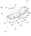
図7は、ロータ4の内周面部4aの展開図である。ロータ4の内周面部4aに配設されたマグネット16は、N極に着磁された6個のマグネット16aと、S極に着磁された5個のマグネット16bと、N極に着磁された磁極部160とS極に着磁された磁極部162とを備えた1個のマグネット16cとを有している。なお、マグネット16cの磁極部160は、マグネット16cの一端に形成され、ホールIC50aが配置された位置M1と、ホールIC50b、50c、50dが配置された位置M2との間に配される。   FIG. 7 is a development view of the inner peripheral surface portion 4 a of the rotor 4. The magnets 16 disposed on the inner peripheral surface portion 4a of the rotor 4 are magnetized to N poles, six magnets 16a magnetized to N poles, five magnets 16b magnetized to S poles, and N poles. And a single magnet 16c having a magnetic pole portion 162 magnetized to the S pole. The magnetic pole 160 of the magnet 16c is formed at one end of the magnet 16c and is disposed between a position M1 where the Hall IC 50a is disposed and a position M2 where the Hall ICs 50b, 50c, and 50d are disposed.

また、磁極部162の軸方向の長さは、磁極部160の軸方向の長さよりも充分長く設定されている。本実施の形態において、磁極部162は、磁極部160の軸方向の長さのおよそ8倍の長さを有している。なお、マグネット16cに形成された磁極部162の軸方向の長さは、マグネット16cの磁極部160の軸方向の長さよりも、十分に大きく形成されていれば良い。   Further, the length of the magnetic pole portion 162 in the axial direction is set sufficiently longer than the length of the magnetic pole portion 160 in the axial direction. In the present embodiment, the magnetic pole portion 162 has a length that is approximately eight times the axial length of the magnetic pole portion 160. Note that the axial length of the magnetic pole portion 162 formed on the magnet 16c only needs to be sufficiently larger than the axial length of the magnetic pole portion 160 of the magnet 16c.

ホールIC50aは、ロータ4の開口周縁部4cに近接した位置M1に配置されるため、マグネット16a、16b、16cの一端から生じた磁束の方向の切り替わりを検出する。ホールIC50b、50c、50dは、マグネット16a、16b、16cに対向する位置M2に配置されているため、マグネット16a、16b、16cの中央から生じた磁束の方向の切り替わりを検出する。   Since the Hall IC 50a is disposed at a position M1 close to the opening peripheral edge 4c of the rotor 4, it detects a change in the direction of the magnetic flux generated from one end of the magnets 16a, 16b, 16c. Since the Hall ICs 50b, 50c, and 50d are arranged at the position M2 facing the magnets 16a, 16b, and 16c, the change of the direction of the magnetic flux generated from the center of the magnets 16a, 16b, and 16c is detected.

図8は、検出センサ6の背面図であり、図9は検出センサ6の背面斜視図である。検出センサ6は、略扇状に形成されており、検出センサ6の外周面部6bには、支持部64が形成され、検出センサ6の内周面部6aには、支持部62とハウジング68とが形成されている。支持部62は、検出センサ6の内周面部6aから突出形成された1対の腕部62a、62bと、1対の腕部62a、62bを連結する連結部62cとを有しており、連結部62cは、螺子などの締結部材によって、ステータコア2の本体部2aに固定される。また、ハウジング68は、腕部62aに向かって開口形成された開口部68a(第1の開口部)と、脚部80aの延出方向に向かって開口形成された開口部68b(第2の開口部)と、開口部68aと開口部68bとを繋ぐガイド部68cと、台形状に形成された壁部68dとを有している。なお、ハウジング68に形成されたガイド部68cは、屈曲形成されており、検出センサ6の外側の底面部6dに対して傾斜している。したがって、ホールIC50a、50b、50c、50dと電気的に接続されるリード線100aは、腕部62aを跨いで開口部68aに挿入され、ガイド部68cに沿って開口部68bに案内される。   FIG. 8 is a rear view of the detection sensor 6, and FIG. 9 is a rear perspective view of the detection sensor 6. The detection sensor 6 is formed in a substantially fan shape, a support portion 64 is formed on the outer peripheral surface portion 6 b of the detection sensor 6, and a support portion 62 and a housing 68 are formed on the inner peripheral surface portion 6 a of the detection sensor 6. Has been. The support portion 62 includes a pair of arm portions 62a and 62b that protrude from the inner peripheral surface portion 6a of the detection sensor 6, and a connection portion 62c that connects the pair of arm portions 62a and 62b. The part 62c is fixed to the main body part 2a of the stator core 2 by a fastening member such as a screw. The housing 68 has an opening 68a (first opening) formed toward the arm 62a and an opening 68b (second opening) formed toward the extending direction of the leg 80a. Part), a guide part 68c connecting the opening part 68a and the opening part 68b, and a wall part 68d formed in a trapezoidal shape. The guide portion 68 c formed in the housing 68 is bent and inclined with respect to the bottom surface portion 6 d outside the detection sensor 6. Therefore, the lead wire 100a electrically connected to the Hall ICs 50a, 50b, 50c, 50d is inserted into the opening 68a across the arm portion 62a, and is guided to the opening 68b along the guide portion 68c.

また、検出センサ6の外側の底面部6dは、検出センサ6の内周面部6aに沿って形成された6個の挿入部72と7個の突出片92a、92bとを有しており、各挿入部72には、開口部68bに案内されたリード線100aが挿入される。なお、挿入部72は、検出センサ6の外側の底面部6dに対してテーパ状に形成された面取り部72bを有している。そのため、リード線100aは、スムーズに挿入部72に挿入される。   Further, the bottom surface portion 6d outside the detection sensor 6 has six insertion portions 72 and seven projecting pieces 92a and 92b formed along the inner peripheral surface portion 6a of the detection sensor 6. The lead wire 100a guided to the opening 68b is inserted into the insertion portion 72. The insertion portion 72 has a chamfered portion 72 b that is tapered with respect to the bottom surface portion 6 d outside the detection sensor 6. Therefore, the lead wire 100a is smoothly inserted into the insertion portion 72.

検出センサ6の外側の底面部6dに形成された1対の突出片92aは、各々、1個のリブ93を有しており、5個の突出片92bは、各々、2個のリブ93を有している。また、5個の突出片92bは、1対の突出片92aの間に等間隔に配されている。そのため、突出片92a、92bに形成されたリブ93は、互いに向かい合って配置される。各挿入部72に挿入されたリード線100aは、各々、突出片92a、92bの間に配され、リブ93によって押しつぶされる。リード線100aは、突出片92a、92bによって確実に保持されるため、挿入部72から抜け落ちることはない。   Each of the pair of protruding pieces 92a formed on the bottom surface portion 6d of the detection sensor 6 has one rib 93, and each of the five protruding pieces 92b has two ribs 93. Have. Further, the five protruding pieces 92b are arranged at equal intervals between the pair of protruding pieces 92a. Therefore, the ribs 93 formed on the protruding pieces 92a and 92b are arranged to face each other. The lead wires 100 a inserted into the respective insertion portions 72 are arranged between the protruding pieces 92 a and 92 b and are crushed by the ribs 93. Since the lead wire 100a is securely held by the projecting pieces 92a and 92b, the lead wire 100a does not fall out of the insertion portion 72.

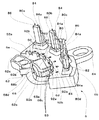
図10は、検出センサ6の斜視図であり、検出センサ6に充填される充填材150は取り除かれている。また、図11は、検出センサ6の分解斜視図である。図12は、センサユニット32の分解斜視図であり、図13は、ベース部材42の背面図である。   FIG. 10 is a perspective view of the detection sensor 6, in which the filler 150 filled in the detection sensor 6 is removed. FIG. 11 is an exploded perspective view of the detection sensor 6. FIG. 12 is an exploded perspective view of the sensor unit 32, and FIG. 13 is a rear view of the base member 42.

図10に示されるように、検出センサ6は、略扇状に形成されたセンサケース60と、センサケース60に収容されるセンサユニット32とを有している。センサケース60は、センサユニット32を収容するセンサユニット収容部66を有しており、センサユニット収容部66の内側の底面部66cには、1対の固定部70が突出形成されている。   As shown in FIG. 10, the detection sensor 6 includes a sensor case 60 formed in a substantially fan shape and a sensor unit 32 accommodated in the sensor case 60. The sensor case 60 has a sensor unit housing portion 66 for housing the sensor unit 32, and a pair of fixing portions 70 are formed to protrude from the bottom surface portion 66 c inside the sensor unit housing portion 66.

図11に示されるように、センサユニット32は、略扇状に形成された基板34と、基板34に固定された略扇形状のベース部材42と、ベース部材42に取り付けられた4個のホールIC50a、50b、50c、50dとを有している。なお、基板34には、1対の貫通孔36と、1対の貫通孔39とが形成されており、貫通孔36には、ベース部材42に形成された固定部49が挿入され、貫通孔39には、固定部70が挿入される。これによって、センサユニット32は、センサユニット収容部66内に固定される。   As shown in FIG. 11, the sensor unit 32 includes a substrate 34 formed in a substantially fan shape, a substantially fan-shaped base member 42 fixed to the substrate 34, and four Hall ICs 50 a attached to the base member 42. , 50b, 50c, 50d. The substrate 34 is formed with a pair of through holes 36 and a pair of through holes 39, and a fixing portion 49 formed in the base member 42 is inserted into the through hole 36. In 39, a fixing part 70 is inserted. As a result, the sensor unit 32 is fixed in the sensor unit housing portion 66.

図12に示されるように、基板34は、略扇形状に形成されており、基板34の内周部34aには、6個の貫通孔38が形成されており、基板34の外周部34bには、貫通孔35a、35b、35cが、各々、4個ずつ形成されている。なお、前述したように、基板34に形成された貫通孔36には、ベース部材42に形成された固定部49が挿入され、基板34に形成された貫通孔39には、センサケース60に形成された固定部70が挿入される。   As shown in FIG. 12, the substrate 34 is formed in a substantially fan shape, and six through holes 38 are formed in the inner peripheral portion 34 a of the substrate 34, and the outer peripheral portion 34 b of the substrate 34 is formed in the outer peripheral portion 34 b. Each has four through holes 35a, 35b, and 35c. As described above, the fixing portion 49 formed in the base member 42 is inserted into the through hole 36 formed in the substrate 34, and the sensor case 60 is formed in the through hole 39 formed in the substrate 34. The fixed part 70 is inserted.

4個のホールIC50a、50b、50c、50dは、各々、マグネット16の磁束の方向の切り替わりを検出するセンサ素子52と、センサ素子52から延出する3本のリード54a、54b、54cとを有している。なお、ホールIC50aの3本のリード54a、54b、54cの長さは、ホールIC50b、50c、50dのリード54a、54b、54cの長さに比べて短い。   Each of the four Hall ICs 50a, 50b, 50c, 50d has a sensor element 52 that detects a change in the direction of the magnetic flux of the magnet 16 and three leads 54a, 54b, 54c extending from the sensor element 52. is doing. Note that the lengths of the three leads 54a, 54b, 54c of the Hall IC 50a are shorter than the lengths of the leads 54a, 54b, 54c of the Hall ICs 50b, 50c, 50d.

図12、図13に示されるように、ベース部材42は、略扇形状の本体部44と、本体部44の一方の平面から突出形成された4個のホルダ片46a、46b、46c、46dと、他方の平面から突出形成された固定部49とを有している。ホルダ片46a、46b、46c、46dは、各々、本体部44の一方の平面から突出形成された基端部47aと、基端部47aから延出形成された先端部47bとを有しており、先端部47bの幅は、基端部47aの幅よりも狭く形成されている。なお、各ホルダ片46a、46b、46c、46dには、ホールIC50a、50b、50c、50dが取り付けられる。   As shown in FIGS. 12 and 13, the base member 42 includes a substantially fan-shaped main body 44, and four holder pieces 46 a, 46 b, 46 c, 46 d that protrude from one plane of the main body 44. And a fixing portion 49 that protrudes from the other plane. Each of the holder pieces 46a, 46b, 46c, and 46d has a base end portion 47a that protrudes from one plane of the main body portion 44 and a tip end portion 47b that extends from the base end portion 47a. The width of the distal end portion 47b is formed narrower than the width of the proximal end portion 47a. In addition, Hall IC50a, 50b, 50c, 50d is attached to each holder piece 46a, 46b, 46c, 46d.

ホルダ片46aの先端部47bの長さは、ホルダ片46b、46c、46dの先端部47bの長さよりも短く形成されている。そのため、ホールIC50aは、ホールIC50b、50c、50dが配置された位置よりも、基板34に近接した位置に配される。そのため、図7で示したように、ホールIC50aは、ロータ4の開口周縁部4cに近接した位置M1に配置され、ホールIC50b、50c、50dは、マグネット16a、16b、16cに対向する位置M2に配置される。   The length of the tip end portion 47b of the holder piece 46a is shorter than the length of the tip end portion 47b of the holder pieces 46b, 46c, 46d. Therefore, the Hall IC 50a is arranged at a position closer to the substrate 34 than the position where the Hall ICs 50b, 50c, 50d are arranged. Therefore, as shown in FIG. 7, the Hall IC 50a is arranged at the position M1 close to the opening peripheral edge 4c of the rotor 4, and the Hall ICs 50b, 50c, 50d are at the position M2 facing the magnets 16a, 16b, 16c. Be placed.

さらに、ベース部材42の本体部44は、切り欠き部45a、45b、45cを、各々、4個ずつ有しており、各切り欠き部45a、45b、45cは、基板34に形成された貫通孔35a、35b、35cと重なって配置される。そのため、ホルダ片46a、46b、46c、46dに取り付けられたホールIC50a、50b、50c、50dのリード54a、54b、54cは、ベース部材42に形成された切り欠き部45a、45b、45cを介して、基板34に形成された貫通孔35a、35b、35cに挿入される。   Further, the main body portion 44 of the base member 42 has four cutout portions 45 a, 45 b, 45 c, and each cutout portion 45 a, 45 b, 45 c is a through hole formed in the substrate 34. 35a, 35b, and 35c are overlapped. Therefore, the leads 54a, 54b, and 54c of the Hall ICs 50a, 50b, 50c, and 50d attached to the holder pieces 46a, 46b, 46c, and 46d pass through the notches 45a, 45b, and 45c formed in the base member 42. The through holes 35a, 35b and 35c formed in the substrate 34 are inserted.

なお、各ホルダ片46a、46b、46c、46dには、切り欠き部45a、45b、45cに対応する溝部48a、48b、48cが形成されている。したがって、ホールIC50a、50b、50c、50dのリード54a、54b、54cは、各々、溝部48a、48b、48c内に埋没されるため、ホルダ片46a、46b、46c、46dは、大型化することはない。   Each holder piece 46a, 46b, 46c, 46d is formed with groove portions 48a, 48b, 48c corresponding to the notches 45a, 45b, 45c. Therefore, since the leads 54a, 54b, and 54c of the Hall ICs 50a, 50b, 50c, and 50d are buried in the grooves 48a, 48b, and 48c, the holder pieces 46a, 46b, 46c, and 46d are not enlarged. Absent.

また、基板34の内周部34aに形成された6個の貫通孔38は、各々、距離L1だけ離れて等間隔に配置されている。同様にして、センサケース60に形成された6個の挿入部72は、各々、距離L1だけ離れて等間隔に形成されている。そのため、センサユニット収容部66にセンサユニット32が固定されると、基板34に形成された貫通孔38は、各々、挿入部72と重なって配置される。   Further, the six through holes 38 formed in the inner peripheral portion 34a of the substrate 34 are spaced apart from each other by a distance L1 and are equally spaced. Similarly, the six insertion portions 72 formed in the sensor case 60 are formed at equal intervals apart from each other by a distance L1. Therefore, when the sensor unit 32 is fixed to the sensor unit housing portion 66, the through holes 38 formed in the substrate 34 are arranged so as to overlap the insertion portion 72.

そして、前述したように、挿入部72には、リード線100aが挿入される。挿入部72は、センサユニット収容部66の内側の底面部66cから、わずかに盛り上がって形成された隆起部72aを有している。そのため、挿入部72と基板34との間には、わずかの隙間しか形成されない。したがって、検出センサ6の外側の底面部6dから挿入部72に挿入されたリード線100aは、基盤34に形成された貫通孔38に挿入される。   As described above, the lead wire 100a is inserted into the insertion portion 72. The insertion portion 72 has a raised portion 72 a formed so as to rise slightly from the bottom surface portion 66 c inside the sensor unit housing portion 66. For this reason, only a slight gap is formed between the insertion portion 72 and the substrate 34. Accordingly, the lead wire 100 a inserted into the insertion portion 72 from the bottom surface portion 6 d outside the detection sensor 6 is inserted into the through hole 38 formed in the base 34.

基板34に形成された貫通孔35a、35b、35cに挿入された各リード54a、54b、54cは、ハンダにて基板34と電気的に接続される。同様にして基板34に形成された貫通孔38に挿入されたリード線100aは、ハンダにて基板34と電気的に接続される。すなわち、リード54a、54b、54cと、リード線100aとは、各々、電気的に接続される。   The leads 54a, 54b, 54c inserted into the through holes 35a, 35b, 35c formed in the substrate 34 are electrically connected to the substrate 34 by soldering. Similarly, the lead wire 100a inserted into the through hole 38 formed in the substrate 34 is electrically connected to the substrate 34 by solder. That is, the leads 54a, 54b, 54c and the lead wire 100a are electrically connected to each other.

なお、前述したように、センサユニット32は、ベース部材44に形成された固定部49と、センサケース60に形成された固定部70とによって、センサケース60に固定されている。すなわち、作業者は、センサユニット32を支持することなく、リード54a、54b、54cと基板34とのハンダ付け作業および、リード線100aと基板34とのハンダ付け作業を行うことができる。   As described above, the sensor unit 32 is fixed to the sensor case 60 by the fixing portion 49 formed on the base member 44 and the fixing portion 70 formed on the sensor case 60. That is, the operator can perform the soldering operation between the leads 54 a, 54 b, 54 c and the substrate 34 and the soldering operation between the lead wire 100 a and the substrate 34 without supporting the sensor unit 32.

センサユニット収容部66の内側の底面部66cには、1対の台座部74が形成されている。センサユニット収容部66に配される基板34の外周部34bは、ベース部材42の本体部44によって支持され、基板34の内周部34aは、台座部74によって支持される。台座部74の高さは、ベース部材42の本体部44の厚さと等しいため、センサユニット32は、センサユニット収容部66内に安定して配置される。   A pair of pedestal portions 74 are formed on the bottom surface portion 66 c inside the sensor unit housing portion 66. The outer peripheral portion 34 b of the substrate 34 disposed in the sensor unit housing portion 66 is supported by the main body portion 44 of the base member 42, and the inner peripheral portion 34 a of the substrate 34 is supported by the pedestal portion 74. Since the height of the pedestal 74 is equal to the thickness of the main body 44 of the base member 42, the sensor unit 32 is stably disposed in the sensor unit housing 66.

さらに、図1に示されるように、リード線100aは、挿入部72を介して基板34に接続される。そのため、リード線100aと基板34との接続部101は、センサユニット収容部66の内側の底面部66cと基板34との間に配されない。したがって、基板34は、センサユニット収容部66の内側の底面部66cに近接して配置される。すなわち、ホールIC50b、50c、50dは、マグネット16の中央に近接して配置され、マグネット16の磁束の方向の切り替わりを確実に検出する。   Further, as shown in FIG. 1, the lead wire 100 a is connected to the substrate 34 via the insertion portion 72. Therefore, the connecting portion 101 between the lead wire 100 a and the substrate 34 is not disposed between the bottom surface portion 66 c inside the sensor unit housing portion 66 and the substrate 34. Accordingly, the substrate 34 is disposed in the vicinity of the bottom surface portion 66 c inside the sensor unit housing portion 66. That is, the Hall ICs 50b, 50c, and 50d are arranged close to the center of the magnet 16 and reliably detect the switching of the direction of the magnetic flux of the magnet 16.

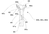
図14は、センサケース60の正面図であり、図15は、脚部80aの断面図であり、図16は、脚部80b、80c、80dの断面図である。図17は、凹部88の拡大図である。図18は、挿入部72の拡大図であり、図19は、挿入部72の断面図である。   14 is a front view of the sensor case 60, FIG. 15 is a cross-sectional view of the leg portion 80a, and FIG. 16 is a cross-sectional view of the leg portions 80b, 80c, and 80d. FIG. 17 is an enlarged view of the recess 88. FIG. 18 is an enlarged view of the insertion portion 72, and FIG. 19 is a cross-sectional view of the insertion portion 72.

図15、図16に示されるように、センサケース60に形成された脚部80a、80b、80c、80dの基端部82は、各々、凹部88を有しており、中間部84は、各々、凹部90を有している。凹部88は、センサユニット収容部66の内側の底面部66cに向かって開口形成されており、凹部90は、凹部88の底面部88aに向かって開口形成されている。したがって、センサユニット収容部66にセンサユニット32が固定されると、ホールIC50a、50b、50c、50dは、凹部90内に挿入される。なお、凹部88の開口部88bの開口面積は、凹部90の開口部90bの開口面積よりも大きい。   As shown in FIGS. 15 and 16, the base end portions 82 of the leg portions 80 a, 80 b, 80 c, and 80 d formed on the sensor case 60 each have a recess 88, and the intermediate portions 84 are respectively And has a recess 90. The concave portion 88 is formed to open toward the bottom surface portion 66 c inside the sensor unit housing portion 66, and the concave portion 90 is formed to open toward the bottom surface portion 88 a of the concave portion 88. Therefore, when the sensor unit 32 is fixed to the sensor unit housing portion 66, the Hall ICs 50a, 50b, 50c, and 50d are inserted into the recess 90. Note that the opening area of the opening 88 b of the recess 88 is larger than the opening area of the opening 90 b of the recess 90.

凹部88の壁部88cは、センサユニット収容部66の内側の底面部66cに対して傾斜して形成されている。そのため、各ホールIC50a、50b、50c、50dは、各々、凹部88の壁部88cに沿って、凹部90内に挿入される。すなわち、作業者は、容易にホールIC50a、50b、50c、50dを、凹部90内に配することができる。   The wall portion 88 c of the recess 88 is formed to be inclined with respect to the bottom surface portion 66 c inside the sensor unit housing portion 66. Therefore, each Hall IC 50a, 50b, 50c, 50d is inserted into the recess 90 along the wall 88c of the recess 88. That is, the operator can easily place the Hall ICs 50a, 50b, 50c, 50d in the recess 90.

また、図17に示されるように、凹部90には、2個のリブ91aが形成されている。そのため、凹部90内に挿入されたホールIC50a、50b、50c、50dは、所定の位置に配置される。   Further, as shown in FIG. 17, two ribs 91 a are formed in the recess 90. Therefore, the Hall ICs 50a, 50b, 50c, 50d inserted into the recess 90 are arranged at predetermined positions.

脚部80a内に形成されたリブ91aの長さは、脚部80b、80c、80d内に形成されたリブ91aの長さよりも長く形成されている。そのため、ホールIC50aを、ロータ4の開口周縁部4cに近接した位置M1上に配置した場合であっても、ホールIC50aは、リブ91aに当接するため、所定の位置に配置される。   The length of the rib 91a formed in the leg part 80a is longer than the length of the rib 91a formed in the leg parts 80b, 80c, 80d. Therefore, even when the Hall IC 50a is disposed on the position M1 close to the opening peripheral edge portion 4c of the rotor 4, the Hall IC 50a is disposed at a predetermined position because it is in contact with the rib 91a.

前述したように、センサユニット収容部66内には、充填材150が注入される。図17に示されるように、センサユニット収容部66に形成された凹部88は、幅W1を有しており、図13に示されるように、ベース部材42の本体部44は、凹部88の幅W1よりも狭い幅W2を有している。そのため、ホールIC50a、50b、50c、50dが、凹部90内に配されても、凹部88の開口部88bは、ベース部材42の本体部44によって覆われることはない。したがって、センサユニット収容部66に注入される充填材150は、ベース部材42によって阻害されることなく、凹部90内に注入される。   As described above, the filler 150 is injected into the sensor unit housing portion 66. As shown in FIG. 17, the recess 88 formed in the sensor unit housing portion 66 has a width W <b> 1, and as shown in FIG. 13, the main body 44 of the base member 42 has a width of the recess 88. The width W2 is narrower than W1. Therefore, even if the Hall ICs 50 a, 50 b, 50 c, 50 d are arranged in the recess 90, the opening 88 b of the recess 88 is not covered by the main body 44 of the base member 42. Therefore, the filler 150 injected into the sensor unit housing portion 66 is injected into the recess 90 without being obstructed by the base member 42.

前述したように、リード54a、54b、54cは、ホルダ片46a、46b、46c、46dに形成された溝部48a、48b、48c内に埋没されるため、ホルダ片46a、46b、46c、46dは、大型化しない。さらに、凹部90には、3個の溝部91bが形成されている。したがって、ホルダ片46a、46b、46c、46dは、凹部90を密閉することなく、凹部90内に配置される。そのため、充填材150は、ホルダ片46a、46b、46c、46dによって阻害されることなく、凹部90内に注入される。   As described above, since the leads 54a, 54b, 54c are buried in the grooves 48a, 48b, 48c formed in the holder pieces 46a, 46b, 46c, 46d, the holder pieces 46a, 46b, 46c, 46d are Does not increase in size. Further, the groove 90 is formed with three groove portions 91b. Therefore, the holder pieces 46 a, 46 b, 46 c, 46 d are disposed in the recess 90 without sealing the recess 90. Therefore, the filler 150 is injected into the recess 90 without being blocked by the holder pieces 46a, 46b, 46c, 46d.

図18、図19に示されるように、センサケース60に形成された挿入部72には、6個のリブ73が等間隔に形成されている。そのため、リード線100aは、リブ73によって押し潰されながら、挿入部72に挿入される。リード線100aがリブ73によって押し潰されると、リード線100aは変形し、リブ73の間の隙間に侵入する。そのため、センサユニット収容部66に注入された充填材は、挿入部72を通って、センサケース60の外部へ漏洩することはない。   As shown in FIGS. 18 and 19, six ribs 73 are formed at equal intervals in the insertion portion 72 formed in the sensor case 60. Therefore, the lead wire 100 a is inserted into the insertion portion 72 while being crushed by the rib 73. When the lead wire 100 a is crushed by the rib 73, the lead wire 100 a is deformed and enters the gap between the ribs 73. Therefore, the filler injected into the sensor unit housing portion 66 does not leak outside the sensor case 60 through the insertion portion 72.

また、前述したように、リード線100aは、検出センサ6の外側の底面部6dから、挿入部72を介して、基板34に接続される。そのため、リード線100aは、センサユニット収容部66の開口周縁部66aを跨ぐことはない。したがって、充填材150は、リード線100aを伝って、検出センサ6の外部へと漏洩することはない。   Further, as described above, the lead wire 100 a is connected to the substrate 34 from the bottom surface portion 6 d outside the detection sensor 6 via the insertion portion 72. Therefore, the lead wire 100a does not straddle the opening peripheral edge portion 66a of the sensor unit housing portion 66. Therefore, the filler 150 does not leak to the outside of the detection sensor 6 through the lead wire 100a.

さらに、図18、図19に示されるように、リブ73は三角錐状に形成されているため、リード線100aを挿入部72に挿入する際に、リード線100aとリブ73との接触面積は、小さくなる。したがって、作業者は、効率よく、リード線100aを挿入部72に挿入することができる。   Further, as shown in FIGS. 18 and 19, since the rib 73 is formed in a triangular pyramid shape, when the lead wire 100a is inserted into the insertion portion 72, the contact area between the lead wire 100a and the rib 73 is as follows. , Get smaller. Therefore, the operator can efficiently insert the lead wire 100a into the insertion portion 72.

また、図12で示したように、ベース部材42の略中央には、半円形状の切り欠き部45dが形成されており、ベース部材42に固定される基板34の略中央には、貫通孔37が形成されている。基板34に形成された貫通孔37は、ベース部材42に形成された切り欠き部45dと重なって配置されるため、センサユニット収容部66の内側の底面部66cは、切り欠き部45dと貫通孔37とを介して、露出している。したがって、センサケース60の内側の底面部66cと、センサユニット32との間に蓄積される空気は、切り欠き部45dに重なって配置された貫通孔37を介して、センサケース60の外部に輩出される。すなわち、センサユニット32とセンサユニット収容部66の内側の底面部66cとの間に空気が溜まらないため、センサユニット32は、充填材150によって、確実に保護される。   As shown in FIG. 12, a semicircular cutout 45d is formed in the approximate center of the base member 42, and a through hole is provided in the approximate center of the substrate 34 fixed to the base member 42. 37 is formed. Since the through hole 37 formed in the substrate 34 is disposed so as to overlap the notch portion 45d formed in the base member 42, the bottom surface portion 66c inside the sensor unit housing portion 66 is connected to the notch portion 45d and the through hole. 37 and is exposed. Therefore, the air accumulated between the bottom surface portion 66c inside the sensor case 60 and the sensor unit 32 is produced outside the sensor case 60 through the through-hole 37 disposed so as to overlap the notch 45d. Is done. That is, since air does not accumulate between the sensor unit 32 and the bottom surface portion 66 c inside the sensor unit housing portion 66, the sensor unit 32 is reliably protected by the filler 150.

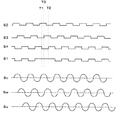
図20は、制御部が生成する信号の波形を示す図である。   FIG. 20 is a diagram illustrating a waveform of a signal generated by the control unit.

前述したように、ホールIC50a、50b、50c、50dのリード54a、54b、54cは、基板32を介して、リード線100aと電気的に接続されており、リード線100aは、制御部と電気的に接続している。そのため、ホールIC50a、50b、50c、50dが、マグネット16a、16b、16cから生じた磁束の方向の切り替わりを検出すると、図20に示されるように、制御部は、信号S1、S2、S3、S4を生成する。   As described above, the leads 54a, 54b, 54c of the Hall ICs 50a, 50b, 50c, 50d are electrically connected to the lead wire 100a via the substrate 32, and the lead wire 100a is electrically connected to the control unit. Connected to. Therefore, when the Hall ICs 50a, 50b, 50c, and 50d detect the change of the direction of the magnetic flux generated from the magnets 16a, 16b, and 16c, as shown in FIG. 20, the control unit performs signals S1, S2, S3, and S4. Is generated.

すなわち、マグネット16bから生じた磁束を検出していたホールIC50a、50b、50c、50dが、マグネット16aから生じた磁束を検出すると、制御部は、信号S1、S2、S3,S4のレベルをハイに変化させる。また、マグネット16aから生じた磁束を検出していたホールIC50a、50b、50c、50dが、マグネット16bから生じた磁束を検出すると、制御部は、信号S1、S2、S3,S4のレベルをローに変化させる。   That is, when the Hall ICs 50a, 50b, 50c, and 50d that have detected the magnetic flux generated from the magnet 16b detect the magnetic flux generated from the magnet 16a, the control unit sets the levels of the signals S1, S2, S3, and S4 to high. Change. When the Hall ICs 50a, 50b, 50c, and 50d that have detected the magnetic flux generated from the magnet 16a detect the magnetic flux generated from the magnet 16b, the control unit sets the levels of the signals S1, S2, S3, and S4 to low. Change.

また、マグネット16aから生じた磁束を検出していたホールIC50b、50c、50dが、マグネット16cから生じた磁束を検出すると、制御部は、信号S2、S3,S4のレベルをローに変化させる。また、マグネット16cから生じた磁束を検出していたホールIC50b、50c、50dが、マグネット16aから生じた磁束を検出すると、制御部は、信号S2、S3,S4のレベルをハイに変化させる。   When the Hall ICs 50b, 50c, and 50d that have detected the magnetic flux generated from the magnet 16a detect the magnetic flux generated from the magnet 16c, the control unit changes the levels of the signals S2, S3, and S4 to low. When the Hall ICs 50b, 50c, and 50d that have detected the magnetic flux generated from the magnet 16c detect the magnetic flux generated from the magnet 16a, the control unit changes the levels of the signals S2, S3, and S4 to high.

しかしながら、ホールIC50aは、ロータ4の開口周縁部4cに近接した位置M1上に配置されるため、マグネット16a、16b、16cの一端から生じた磁束の方向の切り替わりを検出する。また、マグネット16cの一端に形成された磁極部160は、隣接するマグネット16aの磁極と同一のN極で着磁されている。マグネット16aから生じた磁束を検出していたホールIC50aが、マグネット16cから生じた磁束を検出しても、制御部は、信号S1のレベルを変化させない。同様にして、マグネット16cから生じた磁束を検出していたホールIC50aが、マグネット16aから生じた磁束を検出しても、制御部は、信号S1のレベルを変化させない。   However, since the Hall IC 50a is disposed on the position M1 close to the opening peripheral edge 4c of the rotor 4, the change in the direction of the magnetic flux generated from one end of the magnets 16a, 16b, 16c is detected. In addition, the magnetic pole part 160 formed at one end of the magnet 16c is magnetized with the same N pole as the magnetic pole of the adjacent magnet 16a. Even if the Hall IC 50a that has detected the magnetic flux generated from the magnet 16a detects the magnetic flux generated from the magnet 16c, the control unit does not change the level of the signal S1. Similarly, even if the Hall IC 50a that has detected the magnetic flux generated from the magnet 16c detects the magnetic flux generated from the magnet 16a, the control unit does not change the level of the signal S1.

すなわち、マグネット16aから生じた磁束を検出していたホールIC50aが、マグネット16cから生じた磁束を検出するタイミングT1と、マグネット16cから生じた磁束を検出していたホールIC50aが、マグネット16aから生じた磁束を検出するタイミングT2との間において、制御部は、信号S1のレベルをローに変化させない。そして、制御部は、タイミングT1とタイミングT2の間で、信号S3のレベルをハイに変化させたタイミングT3に基づいて、エンジンを点火する。   That is, the Hall IC 50a that has detected the magnetic flux generated from the magnet 16a detects the magnetic flux generated from the magnet 16c, and the Hall IC 50a that has detected the magnetic flux generated from the magnet 16c is generated from the magnet 16a. Between the timing T2 at which the magnetic flux is detected, the control unit does not change the level of the signal S1 to low. And a control part ignites an engine based on the timing T3 which changed the level of signal S3 to high between the timing T1 and the timing T2.

また、本実施の形態である始動発電機1は、三相交流式のブラシレスモータであるため、ホールIC50b、50c、50dは、各々、V相、W相、U相のコイル10と対応して配置される。そのため、制御部は、ホールIC50b、50c、50dがマグネット16の磁束の方向の切り替わりを検出すると、信号S2、S3,S4を生成し、V相、W相、U相のコイル10に対応させる。そして、制御部は、コイル10に対するロータ4の位置を検出し、所定のタイミングで、各相のコイル10へ電流を供給することにより、始動発電機1を駆動する。   In addition, since starter generator 1 according to the present embodiment is a three-phase AC brushless motor, Hall ICs 50b, 50c, and 50d correspond to V-phase, W-phase, and U-phase coils 10, respectively. Be placed. Therefore, when the Hall ICs 50b, 50c, and 50d detect the switching of the direction of the magnetic flux of the magnet 16, the control unit generates the signals S2, S3, and S4 to correspond to the V-phase, W-phase, and U-phase coils 10. And a control part detects the position of the rotor 4 with respect to the coil 10, and drives the starter generator 1 by supplying an electric current to the coil 10 of each phase at a predetermined timing.

また、本実施の形態において、基板34の略中央に形成された貫通孔37は、左右対称の円状に形成されている。しかしながら、図21に示されるように、貫通孔170の形状は、左右非対称の半円状に形成されても良い。このように構成することで、作業者は、基板34を裏返しにてベース部材42に組み付けることができなくなるため、センサユニット32は、効率よく生産される。   Further, in the present embodiment, the through hole 37 formed in the approximate center of the substrate 34 is formed in a symmetrical circular shape. However, as shown in FIG. 21, the shape of the through-hole 170 may be formed in a left-right asymmetric semicircular shape. With this configuration, the operator cannot assemble the substrate 34 upside down on the base member 42, so that the sensor unit 32 is efficiently produced.

1 始動発電機
2 ステータコア
2a 本体部
2b ティース部
2c 貫通孔
3a、3b 先端部
3c 切り欠き部
4 ロータ
4a 内周面部
4b 底面部
4c 開口周縁部
4d エンボス
6 検出センサ
6a 内周面部
6b 外周面部
6d 底面部
10 コイル
12 ヨーク
12a 底面部
14 ボス部
16 マグネット
16a、16b、16c マグネット
18 マグネットカバー
32 センサユニット
34 基板
34a 内周部
34b 外周部
35a、35b、35c 貫通孔
36、37、38、39 貫通孔
42 ベース部材
44 本体部
45a、45b、45c、45d 切り欠き部
46a、46b、46c、46d ホルダ片
47a 基端部
47b 先端部
48a、48b、48c 溝部
49 固定部
50a、50b、50c、50d ホールIC
54a、54b、54c リード
60 センサケース
62 支持部
62a、62b 腕部
62c 連結部
64 支持部
66 センサユニット収容部
66a 開口周縁部
66c 底面部
68 ハウジング
68a 開口部(第1の開口部)
68b 開口部(第2の開口部)
68c ガイド部
68d 壁部
70 固定部
72 挿入部
72a 隆起部
72b 面取り部
73 リブ
74 台座部
80a、80b、80c、80d 脚部
82 基端部
84 中間部
84a リブ
86 先端部
86a 厚肉部
86b 薄肉部
88 凹部
88a 底面部
88b 開口部
90 凹部
90b 開口部
91a リブ
91b 溝
92a、92b 突出片
93 リブ
100a、100b リード線
101 接続部
102a、102b 保護チューブ
110 インシュレータ
112 壁部
114 ティース保持部
114a、114b 先端部
114c 本体部
114d 溝部
116 切り欠き部
120 端子
130 保持部材
132 螺子
140a、140b、140c、140d 受容部
160、162 磁極部
M1 ホールIC50aが配置された位置
M2 ホールIC50b、50c、50dが配置された位置
S1、S2、S3、S4 信号
Su、Sv、Sw 信号
DESCRIPTION OF SYMBOLS 1 Starter generator 2 Stator core 2a Main-body part 2b Teeth part 2c Through-hole 3a, 3b Tip part 3c Notch part 4 Rotor 4a Inner peripheral surface part 4b Bottom surface part 4c Opening peripheral part 4d Emboss 6 Detection sensor 6a Inner peripheral surface part 6b Outer peripheral surface part 6d Bottom portion 10 Coil 12 Yoke 12a Bottom portion 14 Boss portion 16 Magnets 16a, 16b, 16c Magnet 18 Magnet cover 32 Sensor unit 34 Substrate 34a Inner peripheral portion 34b Outer peripheral portions 35a, 35b, 35c Through holes 36, 37, 38, 39 Through Hole 42 Base member 44 Main body 45a, 45b, 45c, 45d Notch 46a, 46b, 46c, 46d Holder piece 47a Base end 47b Tip 48a, 48b, 48c Groove 49 Fixed part 50a, 50b, 50c, 50d Hole IC
54a, 54b, 54c Lead 60 Sensor case 62 Support part 62a, 62b Arm part 62c Connection part 64 Support part 66 Sensor unit accommodating part 66a Opening edge part 66c Bottom face part 68 Housing 68a Opening part (first opening part)
68b opening (second opening)
68c Guide portion 68d Wall portion 70 Fixed portion 72 Insertion portion 72a Raised portion 72b Chamfered portion 73 Rib 74 Base portions 80a, 80b, 80c, 80d Leg portion 82 Base end portion 84 Intermediate portion 84a Rib 86 Tip portion 86a Thick portion 86b Thin wall portion Portion 88 Recess 88a Bottom portion 88b Opening 90 Recess 90b Opening 91a Rib 91b Grooves 92a, 92b Projection piece 93 Rib 100a, 100b Lead wire 101 Connection portion 102a, 102b Protective tube 110 Insulator 112 Wall portion 114 Teeth holding portion 114a, 114b Tip portion 114c Body portion 114d Groove portion 116 Notch portion 120 Terminal 130 Holding member 132 Screws 140a, 140b, 140c, 140d Receiving portion 160, 162 Magnetic pole portion M1 Position where Hall IC 50a is arranged M2 Hall IC 50b, 50c, 50d Arranged positions S1, S2, S3, S4 signal Su, Sv, Sw signal

Claims (5)

略T字状に形成された複数のティース部を備えた磁性材料からなるステータコアと、前記ステータコアのティース部に巻装されたコイルと、前記ステータコアの周りを回転する碗形状のロータと、前記ロータの内周面に磁極を交互にして配設された複数のマグネットと、前記ステータコア上に配置され、前記ロータの回転位置を検出する検出センサとを有するアウタロータ型の回転電機において、前記検出センサは、略扇状に形成されたセンサケースと、前記センサケース内に収容されるセンサユニットとを有しており、前記センサユニットは、前記マグネットの磁束の方向の切り替わりを検出する複数のホールICと、前記複数のホールICが取り付けられる略扇形状のベース部材と、前記ベース部材に固定され、前記複数のホールICと電気的に接続される扇形状の基板と、前記基板に接続されるリード線とを有しており、前記センサケースの内周面には、前記センサケースから導き出された前記リード線を収束するハウジングが一体的に形成されていることを特徴とするアウタロータ型の回転電機。   A stator core made of a magnetic material having a plurality of teeth portions formed in a substantially T shape, a coil wound around the teeth portions of the stator core, a bowl-shaped rotor rotating around the stator core, and the rotor In the outer rotor type rotating electrical machine having a plurality of magnets arranged with magnetic poles alternately on the inner peripheral surface thereof, and a detection sensor arranged on the stator core and detecting the rotational position of the rotor, the detection sensor is A sensor case formed in a substantially fan shape, and a sensor unit housed in the sensor case, the sensor unit including a plurality of Hall ICs for detecting a change in the direction of magnetic flux of the magnet, A substantially fan-shaped base member to which the plurality of Hall ICs are mounted; and the plurality of Hall ICs fixed to the base member; It has a fan-shaped substrate that is electrically connected and a lead wire connected to the substrate, and the lead wire led out from the sensor case is converged on the inner peripheral surface of the sensor case. An outer rotor type rotating electrical machine, wherein a housing is integrally formed. 請求項1に記載されたアウタロータ型の回転電機において、前記ハウジングは、前記リード線が挿入される第1の開口部と、前記第1の開口部に挿入されたリード線が引き出される第2の開口部と、前記第1の開口部に挿入されたリード線を、前記第2の開口部に案内するガイド部とを備えたことを特徴とするアウタロータ型の回転電機。   2. The outer rotor type rotating electrical machine according to claim 1, wherein the housing includes a first opening into which the lead wire is inserted and a second wire from which the lead wire inserted into the first opening is drawn out. An outer rotor type rotating electrical machine comprising an opening and a guide for guiding a lead wire inserted into the first opening to the second opening. 請求項1または請求項2に記載されたアウタロータ型の回転電機において、前記基板には、前記リード線が挿入される複数の貫通孔が形成されており、前記センサケースの底面には、前記センサケースの内周面に沿って形成された複数の突出片と、前記基板の複数の貫通孔に対応する位置に形成された複数の挿入部とが形成されており、前記リード線は、前記センサケースの底面に形成された挿入部を介して、前記複数の貫通孔に挿入され、前記突出片によって保持されることを特徴とするアウタロータ型の回転電機。   3. The outer rotor type rotating electrical machine according to claim 1, wherein a plurality of through holes into which the lead wires are inserted are formed in the substrate, and the sensor case has a bottom surface on the bottom surface of the sensor case. A plurality of projecting pieces formed along an inner peripheral surface of the case and a plurality of insertion portions formed at positions corresponding to the plurality of through holes of the substrate are formed, and the lead wire is formed of the sensor An outer rotor type rotating electrical machine, wherein the outer rotor type rotating electrical machine is inserted into the plurality of through holes through an insertion portion formed on a bottom surface of the case and held by the protruding pieces. 請求項1から請求項3のいずれか1項に記載されたアウタロータ型の回転電機において、前記検出センサは、前記複数のホールICが取り付けられるベース部材を有しており、前記ベース部材は、扇形状の本体部と、前記本体部から突出形成された1対の第1の固定部とを有しており、前記基板は、前記ベース部材の第1の固定部によって、前記ベース部材の本体部に取り付けられることを特徴とするアウタロータ型の回転電機。   4. The outer rotor type rotating electrical machine according to claim 1, wherein the detection sensor includes a base member to which the plurality of Hall ICs are attached, and the base member is a fan. A main body having a shape and a pair of first fixing portions protruding from the main body, and the substrate is supported by the first fixing portion of the base member. An outer rotor type rotating electrical machine, characterized in that it is attached to the outer rotor type. 請求項1から請求項4のいずれか1項に記載されたアウタロータ型の回転電機において、前記センサケースは、前記センサケースの底面から突出形成された第2の固定部を有しており、前記基板は、前記第2の固定部によって、前記センサケースに固定されることを特徴とするアウタロータ型の回転電機。

The outer rotor type rotating electrical machine according to any one of claims 1 to 4, wherein the sensor case has a second fixing portion that is formed to protrude from a bottom surface of the sensor case, The outer rotor type rotating electrical machine, wherein the substrate is fixed to the sensor case by the second fixing portion.

JP2009039983A 2009-02-23 2009-02-23 Outer rotor type rotating electric machine Pending JP2010200419A (en)

Priority Applications (1)

Application Number Priority Date Filing Date Title
JP2009039983A JP2010200419A (en) 2009-02-23 2009-02-23 Outer rotor type rotating electric machine

Applications Claiming Priority (1)

Application Number Priority Date Filing Date Title
JP2009039983A JP2010200419A (en) 2009-02-23 2009-02-23 Outer rotor type rotating electric machine

Publications (1)

Publication Number Publication Date
JP2010200419A true JP2010200419A (en) 2010-09-09

Family

ID=42824547

Family Applications (1)

Application Number Title Priority Date Filing Date
JP2009039983A Pending JP2010200419A (en) 2009-02-23 2009-02-23 Outer rotor type rotating electric machine

Country Status (1)

Country Link
JP (1) JP2010200419A (en)

Cited By (2)

* Cited by examiner, † Cited by third party
Publication number Priority date Publication date Assignee Title
CN102545523A (en) * 2012-01-20 2012-07-04 西南大学 Sensor mounting assembly for brushless DC motor of motor-driven device
WO2020015360A1 (en) * 2018-07-14 2020-01-23 中山大洋电机股份有限公司 Dc brushless outer rotor motor

Cited By (3)

* Cited by examiner, † Cited by third party
Publication number Priority date Publication date Assignee Title
CN102545523A (en) * 2012-01-20 2012-07-04 西南大学 Sensor mounting assembly for brushless DC motor of motor-driven device
WO2020015360A1 (en) * 2018-07-14 2020-01-23 中山大洋电机股份有限公司 Dc brushless outer rotor motor
US11404940B2 (en) 2018-07-14 2022-08-02 Zhongshan Broad-Ocean Motor Co., Ltd. Brushless direct current motor

Similar Documents

Publication Publication Date Title
JP2010200421A (en) Outer rotor type rotating electric machine
JP5668182B1 (en) Sensor and rotating electric machine using the same
JP2010200418A (en) Outer rotor type rotating electric machine
JP5567377B2 (en) Electric water pump
JP6720032B2 (en) Rotating electric machine
JP5563805B2 (en) Sensor case and rotating electric machine using the same
JP2009089588A (en) Starting generator
JP2016077074A (en) Position detection sensor and rotary electric machine
CN108352757B (en) Rotating electric machine for internal combustion engine
JP2013233030A (en) Starter generator
JP2019097261A (en) Brushless motor
JP2010200417A (en) Outer rotor type rotating electric machine
JP5827034B2 (en) Starting generator
JP2010200420A (en) Outer rotor type rotating electric machine
JP6032340B2 (en) Rotating electric machine for internal combustion engine
JP2016077081A (en) Rotary electric machine
JP6058725B2 (en) Starting generator
JP2010200419A (en) Outer rotor type rotating electric machine
JP2007189841A (en) Brushless motor
JP5523058B2 (en) Insulator for stator and rotating electric machine using the same
CN103151895B (en) Starter-generator
JP2014068420A (en) Mounting structure of sensor case for starter generator
JP2019030143A (en) Connector and motor with connector
JP2019030141A (en) Connector and motor with connector
JP2019030144A (en) Connector and motor with connector