JP2010197014A - Air conditioner - Google Patents
Air conditioner Download PDFInfo
- Publication number
- JP2010197014A JP2010197014A JP2009045344A JP2009045344A JP2010197014A JP 2010197014 A JP2010197014 A JP 2010197014A JP 2009045344 A JP2009045344 A JP 2009045344A JP 2009045344 A JP2009045344 A JP 2009045344A JP 2010197014 A JP2010197014 A JP 2010197014A
- Authority
- JP
- Japan
- Prior art keywords
- support
- collection box
- dust collection
- stopper
- box assembly
- Prior art date
- Legal status (The legal status is an assumption and is not a legal conclusion. Google has not performed a legal analysis and makes no representation as to the accuracy of the status listed.)
- Pending
Links
Images


Landscapes
- Air Filters, Heat-Exchange Apparatuses, And Housings Of Air-Conditioning Units (AREA)
Abstract
Description
この発明は、フィルタの自動清掃機能を備えた空気調和機に関するものである。 The present invention relates to an air conditioner having an automatic filter cleaning function.
空気調和機においては、送風ファンにより吸い込んだ室内空気を、熱交換器を通過させることによって加熱または冷却して室内に返流させるが、空気中に浮遊する塵埃が熱交換器を汚染するのを防止するため、熱交換器の空気流入側にフィルタが設置されている。このフィルタに塵埃が付着し目詰まりしてフィルタの通風抵抗が増大すると、空気調和機の空調能力が低下すると共に、消費電力が増大する。このような不都合を解消するため、フィルタ自動清掃機能を備えた空気調和機がよく知られている。 In an air conditioner, indoor air sucked by a blower fan is heated or cooled by passing through a heat exchanger and returned to the room, but dust floating in the air contaminates the heat exchanger. In order to prevent this, a filter is installed on the air inflow side of the heat exchanger. When dust adheres to the filter and becomes clogged and the ventilation resistance of the filter increases, the air conditioning capability of the air conditioner decreases and the power consumption increases. In order to eliminate such inconvenience, an air conditioner having an automatic filter cleaning function is well known.
例えば、フィルタと、掻き取りブラシと、塵埃回収箱とで構成される清掃ユニットを備えた空気調和機が提案されている(例えば、特許文献1参照)。 For example, an air conditioner including a cleaning unit including a filter, a scraping brush, and a dust collection box has been proposed (see, for example, Patent Document 1).
上記特許文献1に記載された空気調和機は、フィルタから除去した塵埃は塵埃回収箱に溜められるようになっており、その塵埃を塵埃回収箱を取り外して捨てるようにしている。しかし、本体から取り外した塵埃回収箱の開閉機構に関する記載があるが、塵埃回収箱を本体から取り外す方法についての言及は特に見当たらない。 In the air conditioner described in Patent Document 1, the dust removed from the filter is stored in a dust collection box, and the dust is removed by removing the dust collection box. However, although there is a description about the opening / closing mechanism of the dust collection box removed from the main body, there is no mention of a method for removing the dust collection box from the main body.
従来の空気調和機は、塵埃回収箱の取り外し方法が判り難い場合が多い。また塵埃回収箱の取り外しに際して面倒な作業を強いられることもあった。さらに、塵埃回収箱を安定して取り外すことが困難な場合も多く、例えば塵埃回収箱を急激に外したり、塵埃回収箱が急激に飛び出して抜け落ちるようなことがあると、塵埃回収箱内の塵埃が周辺に飛び散って、本体内部や室内を汚してしまうといった不具合が生じることもあった。 In conventional air conditioners, it is often difficult to understand how to remove the dust collection box. In addition, troublesome work may be required when removing the dust collection box. Furthermore, it is often difficult to remove the dust collection box stably. For example, if the dust collection box is suddenly removed or the dust collection box jumps out and falls off, the dust in the dust collection box May scatter to the surroundings, causing the inside of the main body or the interior to become dirty.
この発明は、上記のような課題を解決するためになされたもので、ユーザーが清掃ユニットから塵埃回収箱を容易に取り外すことができ、かつその取り付けが確実にできるフィルタ自動清掃ユニットを備えた、使い易く信頼性の高い空気調和機を提供することを目的とする。 The present invention was made to solve the above-described problems, and includes a filter automatic cleaning unit that allows a user to easily remove the dust collection box from the cleaning unit and to ensure that the mounting is performed. An object is to provide an air conditioner that is easy to use and highly reliable.
この発明に係る空気調和機は、フィルタに付着した塵埃を除去する清掃ユニットを備えた空気調和機であって、
清掃ユニットは、
フィルタが移動するフィルタレールを有する支持体と、
支持体に着脱自在に取り付けられ、塵埃掻き取り部と、塵埃掻き取り部の下方に取り付けられる塵埃回収箱とを有し、空気調和機の前面部に左右方向に取り付けられる塵埃回収箱組立と、を備え、
塵埃掻き取り部は、左右方向の一端に支持体の取り付け穴に係合する軸を有するとともに、左右方向の他端に支持体の固定穴に係合し、バネにより左右方向に進退可能なストッパーを有し、
ストッパーの先端の支持体側の面に、支持体の当接部に当接する面取り部が形成され、ストッパーが支持体側に押されることにより面取り部が支持体の当接部に当接してバネが縮み、ストッパーが内側に移動し、その後支持体の固定穴に係合するものである。
An air conditioner according to the present invention is an air conditioner including a cleaning unit for removing dust attached to a filter,
The cleaning unit
A support having a filter rail through which the filter moves;
A dust collection box assembly that is detachably attached to the support and has a dust scraping portion and a dust collection box that is attached below the dust scraping portion, and is attached to the front portion of the air conditioner in the left-right direction; With
The dust scraper has a shaft that engages with the mounting hole of the support at one end in the left-right direction, and a stopper that engages with the fixing hole of the support at the other end in the left-right direction and can be advanced and retracted in the left-right direction by a spring. Have
A chamfered portion that abuts against the abutting portion of the support is formed on the surface on the support side of the tip of the stopper, and when the stopper is pushed toward the support side, the chamfered portion abuts against the abutting portion of the support and the spring contracts The stopper moves inward and then engages with the fixing hole of the support.
この発明に係る空気調和機は、ストッパーが支持体側に押されることによりストッパーの先端の支持体側の面に形成された面取り部が支持体の当接部に当接してバネが縮み、ストッパーが内側に移動し、その後支持体の固定穴に係合するので、塵埃回収箱組立の支持体への取り付け作業が簡潔で判りやすい。 In the air conditioner according to the present invention, when the stopper is pushed to the support side, the chamfered portion formed on the support side surface at the tip of the stopper comes into contact with the contact portion of the support body and the spring contracts, and the stopper , And then engages with the fixing hole of the support, so that the operation of attaching the dust collection box assembly to the support is simple and easy to understand.
実施の形態1.
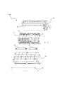
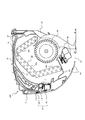
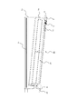
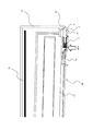
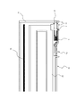
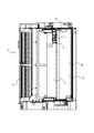
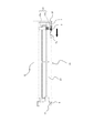
図1乃至図13は実施の形態1を示す図で、図1は空気調和機100の斜視図、図2は空気調和機100の分解斜視図、図3は清掃ユニット3の正面図、図4は図1のZ−Z断面図、図5は図4で前面パネル9を開いた状態を示す断面図、図6は塵埃回収箱組立(右)2bを支持体11に取り付ける途中の状態を示す図、図7は図6の部分拡大図、図8は塵埃回収箱組立(右)2bが支持体11に当接した状態を示す図、図9は図8の部分拡大図、図10は塵埃回収箱組立(右)2bが支持体11に固定された状態を示す図、図11は図10の部分拡大図、図12は清掃ユニット3の部分(右側)正面図、図13は清掃ユニット3の部分(右側)斜視図である。
Embodiment 1 FIG.
FIGS. 1 to 13 are diagrams showing the first embodiment, FIG. 1 is a perspective view of the
図1乃至図5により、空気調和機100の全体構成を説明する。尚、ここでは、室内機と室外機とを備えるセパレート式の空調機の室内機を空気調和機100と呼ぶ。
The overall configuration of the
図1に示すように、空気調和機100は、本体ユニット16、外装ケース15、前面パネル9等により略箱形状の外郭が形成される。空気調和機100の上部(天面)に室内の空気を吸い込む吸込口20が設けられ、下部に調和空気を室内に吹き出す吹出口21が形成されている。
As shown in FIG. 1, in the
図2は空気調和機100の分解斜視図である。空気調和機100は、室内空気と冷凍サイクルの冷媒とが熱交換を行う熱交換器30、送風機40(図2では図示せず、図4参照)等を搭載した本体ユニット16、フィルタ1a,1bの移動を可能とするフィルタレール17(図2では図示せず、図4参照)を有する支持体11と、塵埃回収箱組立(左)2a及び塵埃回収箱組立(右)2bとを有する清掃ユニット3、外装ケース15及び前面パネル9とを少なくとも備える。
FIG. 2 is an exploded perspective view of the
塵埃回収箱組立(左)2a、塵埃回収箱組立(右)2bを、特許請求の範囲等では、単に「塵埃回収箱組立」とする。 In the claims and the like, the dust collection box assembly (left) 2a and the dust collection box assembly (right) 2b are simply referred to as “dust collection box assembly”.
フィルタ1a,1bは、左右にわかれて設けられる。フィルタ1aが空気調和機100を正面から見て左側、フィルタ1bが右側である。
The
塵埃回収箱組立(左)2aは、フィルタ1aの塵埃を除去する。また、塵埃回収箱組立(右)2bは、フィルタ1bの塵埃を除去する。
The dust collection box assembly (left) 2a removes dust from the filter 1a. The dust collection box assembly (right) 2b removes dust from the
図3に示すように、フィルタ1a,1bの自動清掃を行う清掃ユニット3は、支持体11の前面下部に塵埃回収箱組立(左)2a及び塵埃回収箱組立(右)2bとが取り付けられる。
As shown in FIG. 3, the
図4は図1のZ−Z断面図である。図4により、空気調和機100の内部構成について説明する。但し、本実施の形態は、清掃ユニット3(特に、塵埃回収箱組立(左)2a及び塵埃回収箱組立(右)2b)に特徴があるので、その他の構成については、簡単に説明する。
FIG. 4 is a ZZ cross-sectional view of FIG. The internal configuration of the
本体ユニット16には、冷凍サイクルを室外機の圧縮機(図示せず)等とともに構成する熱交換器30、室内空気を吸込口20から吸い込み、吹出口21から調和空気を室内へ吹出すように送風を行う送風機40等が搭載される。
The
熱交換器30は、逆V字形状で送風機40を取り囲むように配置される。熱交換器30は、前面上部熱交換器30a、前面下部熱交換器30b及び背面熱交換器30cを備える。
The
送風機40の下流に位置する吹出口21には、吹出口21から室内へ吹出される調和空気の風向を制御する前面上部熱交換器30a、前面下部熱交換器30b及び背面熱交換器30cが設けられる。左右風向制御板50は、室内へ吹出される調和空気の左右方向の風向を制御する。また、上下風向制御板60は、室内へ吹出される調和空気の上下方向の風向を制御する。
The
前面下部熱交換器30bの下方に、熱交換器30に付着する結露水を受けるドレンパン70が形成されている。ドレンパン70の裏側は、風路の一構成部材となっている。
A
清掃ユニット3は、熱交換器30の上流側に設けられる。フィルタ1bは、支持体11のフィルタレール17に挿入され、通常は吸込口20に対向する位置にある(図4は通常の位置)。清掃ユニット3による自動清掃が開始すると、フィルタ1bは支持体11のフィルタレール17に沿って往復する。
The
図4では塵埃回収箱組立(右)2bを図示しているので、以下、塵埃回収箱組立(右)2bについて説明する。塵埃回収箱組立(左)2aも左右の長さが塵埃回収箱組立(右)2bよりも長い点以外は、塵埃回収箱組立(右)2bと同様である。長さ以外は、塵埃回収箱組立(左)2aと塵埃回収箱組立(右)2bとは鏡面対称である。 Since FIG. 4 shows the dust collection box assembly (right) 2b, the dust collection box assembly (right) 2b will be described below. The dust collection box assembly (left) 2a is the same as the dust collection box assembly (right) 2b except that the left and right lengths are longer than the dust collection box assembly (right) 2b. Except for the length, the dust collection box assembly (left) 2a and the dust collection box assembly (right) 2b are mirror-symmetric.
塵埃回収箱組立(左)2aと塵埃回収箱組立(右)2bとの長さが異なる理由は、以下のとおりである。熱交換器30の右側に冷媒配管、ドレン配管等を配設するスペースが必要なため、本体ユニット16の中心は、熱交換器30の中心と一致していない。外装ケース15の略中心部に、赤外線センサ24(図1参照)を設けるため、塵埃回収箱組立(左)2aと塵埃回収箱組立(右)2bもそれに合わせた配置になる。塵埃回収箱組立(左)2aと塵埃回収箱組立(右)2bとの境界が、本体ユニット16の中心と略一致する。従って、塵埃回収箱組立(左)2aが塵埃回収箱組立(右)2bよりも長くなる。
The reason why the lengths of the dust collection box assembly (left) 2a and the dust collection box assembly (right) 2b are different are as follows. Since a space for arranging a refrigerant pipe, a drain pipe and the like is required on the right side of the
塵埃回収箱組立(右)2bは、掻き取りブラシ4、ストッパー7、突起部14等を有する塵埃掻き取り部25と、この塵埃掻き取り部25の下部に取り付けられ、フィルタ1bの塵埃を掻き取りブラシ4で掻き取った塵埃をためる塵埃回収箱22とを備える。
The dust collection box assembly (right) 2b is attached to a
掻き取りブラシ4は、塵埃掻き取り部25の左右方向の略全長に亘って取り付けられている。自動清掃時に往復動作を行うフィルタ1bに付着した塵埃を掻き取り、塵埃を下方の塵埃回収箱22に落とす。
The scraping brush 4 is attached over substantially the entire length of the
詳細は後述するが、ストッパー7は、バネ5(図6乃至図11)の伸縮を利用して、塵埃回収箱組立(右)2bを支持体11に簡単に取り付けるものである。
Although details will be described later, the
塵埃掻き取り部25に形成された突起部14の役割は、以下のとおりである。図5に示すように、前面パネル9が開いた状態で、例えば、塵埃回収箱組立(右)2bを後述する方法で、支持体11に取り付けたとする。しかし、取り付けが不十分で塵埃回収箱組立(右)2bが、支持体11に固定されていない場合もある。このような場合でも、前面パネル9を閉じることにより前面パネル9が突起部14を押すので、塵埃回収箱組立(右)2bを支持体11に確実に固定することができる。
The role of the
本実施の形態は、塵埃回収箱組立(左)2a、塵埃回収箱組立(右)2bの支持体11への取付方法に特徴がある。
This embodiment is characterized in a method of attaching the dust collection box assembly (left) 2a and the dust collection box assembly (right) 2b to the
図6乃至図11を参照しながら、塵埃回収箱組立(左)2a、塵埃回収箱組立(右)2bの支持体11への取付方法を、塵埃回収箱組立(右)2bを例に説明する。塵埃回収箱組立(左)2aの支持体11への取付方法も同様である。
With reference to FIGS. 6 to 11, a method of attaching the dust collection box assembly (left) 2a and the dust collection box assembly (right) 2b to the
尚、図6乃至図11では、塵埃回収箱組立(右)2bの塵埃回収箱22は見えていない。塵埃掻き取り部25のみが見えている。
6 to 11, the
塵埃回収箱組立(右)2bの塵埃掻き取り部25は、空気調和機100の中心側の端部から横方向に突出している円筒形状の軸8を備える。
The
また、塵埃回収箱組立(右)2bの塵埃掻き取り部25は、軸8と反対側の端部に左右方向に進退可能なストッパー7を備える。ストッパー7にはバネ5が取り付けられていて、通常はこのバネ5に力が作用していない。バネ5に力が作用しない状態では、ストッパー7の先端は、支持体11の右端部よりも突出している。
The
ストッパー7の先端は、支持体11側の角部が面取りされている。ここを面取り部6と呼ぶ。
The tip of the
ストッパー7には、使用者が指でストッパー7を内側に移動させるときに使用する突出部7aが設けられる。
The
ストッパー7の材料は、ポリアセタール(POM:ポリオキシメチレン)樹脂を使用し、抗菌剤を含んでいてもよい。POMは、バランスのとれた機械的特性と優れた成形性、耐疲労性、耐クリープ性、摩擦摩耗特性、耐薬品性を備えていることから、金属の代替材料として自動車部品、電機、各種機械、建材等の分野で広く用いられている。
The material of the
塵埃掻き取り部25の材料は、ABS(アクロル二トリルブタジエンスチレン)樹脂で、やはり抗菌剤を含む。
The material of the
支持体11には、塵埃回収箱組立(右)2bの塵埃掻き取り部25は、空気調和機100の中心側の端部から横方向に突出している円筒形状の軸8が挿入される取り付け穴18が、空気調和機100の中心側に形成されている。
A
また、支持体11には、取り付け穴18の反対側の端部に、ストッパー7の先端が固定される固定穴10が形成されている。
Further, the
さらに、固定穴10より前面側(塵埃回収箱組立(右)2b側)の端部は、ストッパー7の面取り部6と当接する当接部11aになっている。当接部11aは、断面が略四角形の角部で構成される。
Further, the end portion on the front side (the dust collection box assembly (right) 2 b side) from the fixing
塵埃回収箱組立(右)2bを支持体11へ取り付ける場合、先ず、図6、図7に示すように、塵埃回収箱組立(右)2bの塵埃掻き取り部25の空気調和機100の中心側の端部から横方向に突出している円筒形状の軸8を支持体11の取り付け穴18に差し込む。この状態では、軸8と反対側のストッパー7は、支持体11から離れている(支持体11の前面側にいる)。
When attaching the dust collection box assembly (right) 2b to the
次に、支持体11の取り付け穴18に差し込まれた軸8を支点にして、塵埃掻き取り部25のストッパー7側端部を支持体11側に押す。そうすることにより、図8、図9に示すように、ストッパー7の面取り部6が支持体11の当接部11aに先ず当接する。
Next, with the
ストッパー7の面取り部6が支持体11の当接部11aに当接後もさらに塵埃掻き取り部25のストッパー7側端部を支持体11側に押すと、当接部11aからの反力が面取り部6に対して略直角に作用する。従って、その反力のストッパー7及びバネ5方向の成分が存在し、バネ5に作用する。反力によりバネ5は縮む。そのため、ストッパー7は支持体11の内側に移動する。
Even after the chamfered portion 6 of the
さらに、塵埃掻き取り部25のストッパー7側端部を支持体11側に押すと、図10、図11に示すように、ストッパー7の先端が支持体11の固定穴10の位置に到達すると、バネに作用していた力によりストッパー7は固定穴10に一気に入り、塵埃掻き取り部25(塵埃回収箱組立(右)2b)は、支持体11に固定される。
Furthermore, when the end portion of the
塵埃回収箱組立(右)2bを支持体11に挿入する人は、ストッパー7の先端が支持体11の固定穴10の位置に到達すると、バネに作用していた力によりストッパー7は固定穴10に一気に入るので、確かな手応えを感じることができる。
When a person who inserts the dust collection box assembly (right) 2b into the
既に述べたことではあるが、万が一塵埃回収箱組立(右)2bが支持体11に固定されていない(ストッパー7の先端が支持体11の固定穴10に挿入されていない)場合でも、塵埃掻き取り部25のストッパー7の近傍に前方に突出する突起部14(図7、図9、図11)を形成しているので、前面パネル9を閉じることにより突起部14が押され、確実に塵埃回収箱組立(右)2bが支持体11に固定することができる。
As already described, even if the dust collection box assembly (right) 2b is not fixed to the support 11 (the tip of the
図12、図13も参照しながら、塵埃回収箱組立(左)2a、塵埃回収箱組立(右)2bの支持体11からの取り外し方法を、塵埃回収箱組立(右)2bを例に説明する。塵埃回収箱組立(左)2aの支持体11への取り外し方法も同様である。
With reference to FIGS. 12 and 13, a method for removing the dust collection box assembly (left) 2a and the dust collection box assembly (right) 2b from the
塵埃回収箱22の塵埃を捨てるために、塵埃回収箱組立(右)2bを外す場合は、ストッパー7に形成されている人が指でストッパー7を内側に移動させるときに使用する突出部(図12参照)をバネ5の弾性力に抗してバネ5側に移動してストッパー7の先端を固定穴10の内側に位置するような状態にして、図12、図13に示す指掛け部23を前に引けば簡単にストッパー7側が支持体11から外れる。後は、塵埃回収箱組立(右)2bの塵埃掻き取り部25の空気調和機100の中心側の端部から横方向に突出している円筒形状の軸8を支持体11の取り付け穴18から引き抜けば、塵埃回収箱組立(右)2bを支持体11から取り外すことができる。
When removing the dust collection box assembly (right) 2b in order to throw away the dust in the
以上のように、本実施の形態によれば、塵埃回収箱組立(右)2bを支持体11へ取り付ける場合、先ず、塵埃回収箱組立(右)2bの塵埃掻き取り部25の空気調和機100の中心側の端部から横方向に突出している円筒形状の軸8を支持体11の取り付け穴18に差し込む。次に、支持体11の取り付け穴18に差し込まれた軸8を支点にして、塵埃掻き取り部25のストッパー7側端部を支持体11側に押すことにより、ストッパー7の面取り部6が支持体11の当接部11aに先ず当接する。さらに塵埃掻き取り部25のストッパー7側端部を支持体11側に押すと、当接部11aからの反力が面取り部6に対して略直角に作用するため、その反力のストッパー7及びバネ5方向の成分がバネ5に作用してバネ5は縮み、ストッパー7は支持体11の内側に移動する。さらに、塵埃掻き取り部25のストッパー7側端部を支持体11側に押して、ストッパー7の先端が支持体11の固定穴10の位置に到達すると、バネに作用していた力によりストッパー7は固定穴10に一気に入り、塵埃掻き取り部25(塵埃回収箱組立(右)2b)は、支持体11に確実に固定される。尚、塵埃回収箱組立(右)2bを支持体11に挿入する人は、ストッパー7の先端が支持体11の固定穴10の位置に到達すると、バネに作用していた力によりストッパー7は固定穴10に一気に入るので、確かな手応えを感じることができる。
As described above, according to the present embodiment, when attaching the dust collection box assembly (right) 2b to the
また、万が一塵埃回収箱組立(右)2bが支持体11に固定されていない場合でも、塵埃掻き取り部25のストッパー7の近傍に前方に突出する突起部14を形成しているので、前面パネル9を閉じることにより突起部14が押され、確実に塵埃回収箱組立(右)2bが支持体11に固定することができる。
Further, even if the dust collection box assembly (right) 2b is not fixed to the
さらに、塵埃回収箱22の塵埃を捨てるために、塵埃回収箱組立(右)2bを外す場合は、ストッパー7に形成されている人が指でストッパー7を内側に移動させるときに使用する突出部7aをバネ5の弾性力に抗してバネ5側に移動してストッパー7の先端を固定穴10の内側に位置するような状態にして、指掛け部23を前に引けば簡単にストッパー7側が支持体11から外れる。そして、軸8を支持体11の取り付け穴18から引き抜けば、塵埃回収箱組立(右)2bを支持体11から取り外すことができる。
Further, when the dust collection box assembly (right) 2b is removed in order to discard the dust in the
実施の形態2.
図14、図15は実施の形態2を示す図で、図14は清掃ユニット3の部分(右側)正面図、図15は塵埃回収箱組立(右)2bが押し出し装置13で押し出された状態を示す図である。
Embodiment 2. FIG.
14 and 15 show the second embodiment. FIG. 14 is a front view of a part (right side) of the
本実施の形態は、上記実施の形態1の塵埃回収箱組立(左)2a、塵埃回収箱組立(右)2bの塵埃回収箱22に押し出し装置13を追加したものである。その他の構成は、上記実施の形態1の同様であり、説明は省く。
In this embodiment, an
塵埃回収箱組立(左)2a、塵埃回収箱組立(右)2bは、上記実施の形態1と同様に左右の長さ以外は、同様の構成である。長さ以外は、塵埃回収箱組立(左)2aと塵埃回収箱組立(右)2bとは鏡面対称である。 The dust collection box assembly (left) 2a and the dust collection box assembly (right) 2b have the same configuration except for the left and right lengths as in the first embodiment. Except for the length, the dust collection box assembly (left) 2a and the dust collection box assembly (right) 2b are mirror-symmetric.
以下、塵埃回収箱組立(右)2bを例に説明する。図14に示すように、塵埃回収箱組立(右)2bは、塵埃回収箱22(図14では見えていない)に、押し出し装置13が設けられている。
Hereinafter, the dust collection box assembly (right) 2b will be described as an example. As shown in FIG. 14, in the dust collection box assembly (right) 2b, an
押し出し装置13は、押し出し装置本体13aと、バネ13bとを備える。図14、図15では、塵埃回収箱組立(右)2bの塵埃回収箱22の背面に押し出し装置13を設けている。但し、支持体11の前面に押し出し装置13を設けてもよい。
The
押し出し装置13を設けることにより、以下に示す効果が得られる。
(1)塵埃回収箱組立(右)2bを支持体11に取り付ける際に、塵埃回収箱組立(右)2bのストッパー7が支持体11の固定穴10に入っていないと、塵埃回収箱組立(右)2bが押し出し装置13により前方へ押し出され、塵埃回収箱組立(右)2bの支持体11への固定が不十分であることが使用者によくわかる。
(2)塵埃回収箱組立(右)2bを支持体11から取り外す場合、ストッパー7の突出部7aを図14の矢印の方向へ移動させると、押し出し装置13が塵埃回収箱組立(右)2bを前方へ押し出すため、簡単に塵埃回収箱組立(右)2bを支持体11から取り外すことができる。従って、図12、図13に示す指掛け部23は、実施の形態2ではなくてもよい。
By providing the
(1) When the dust collection box assembly (right) 2b is attached to the
(2) When removing the dust collection box assembly (right) 2b from the
以上のように、本実施の形態によれば、押し出し装置本体13aと、バネ13bとを備える押し出し装置13を、塵埃回収箱組立(右)2bの塵埃回収箱22の背面に、または支持体11の前面に設けることにより、塵埃回収箱組立(右)2bを支持体11に取り付ける際に、塵埃回収箱組立(右)2bのストッパー7が支持体11の固定穴10に入っていないと、塵埃回収箱組立(右)2bが押し出し装置13により前方へ押し出され、塵埃回収箱組立(右)2bの支持体11への固定が不十分であることが使用者によくわかる。また、塵埃回収箱組立(右)2bを支持体11から取り外す場合、ストッパー7の突出部7aを移動させると、押し出し装置13が塵埃回収箱組立(右)2bを前方へ押し出すため、簡単に塵埃回収箱組立(右)2bを支持体11から取り外すことができる。
As described above, according to the present embodiment, the
以上、この発明の具体的な実施の形態について説明したが、この発明は上記形態に限定されるものではなく、この発明の範囲内で種々変更して実施することができる。 Although specific embodiments of the present invention have been described above, the present invention is not limited to the above embodiments, and various modifications can be made within the scope of the present invention.
例えば、この発明は室内空気を吸い込んで、冷房、暖房、除湿を行う空気調和機に限らず、室内空気中に含まれる塵埃を捕捉する空気清浄機能を有する空気調和機に対しても適用できる。 For example, the present invention can be applied not only to an air conditioner that sucks room air and performs cooling, heating, and dehumidification, but also to an air conditioner having an air purifying function of capturing dust contained in room air.
さらに、フィルタを移動させて自動清掃作業を行う空気調和機に限らず、清掃ブラシが移動してフィルタに付着した塵埃を除去する構造の空気調和機にも適用できる。 Furthermore, the present invention can be applied not only to an air conditioner that moves a filter to perform automatic cleaning work, but also to an air conditioner that has a structure in which a cleaning brush moves to remove dust attached to a filter.
また、フィルタを移動させる移動方法としては、フィルタに形成したラックをピニオンに噛み合わせて、このピニオンの回転移動によってフィルタを清掃ユニット内に移送する方式のものに限らず、上下プーリと環状ベルトを使用したものでも良く、また従来のような巻取り方式やループ方式であってもよい。 The moving method for moving the filter is not limited to a method in which a rack formed on the filter is engaged with a pinion, and the filter is transferred into the cleaning unit by the rotational movement of the pinion. It may be used, or may be a conventional winding method or loop method.
1a フィルタ、1b フィルタ、2a 塵埃回収箱組立(左)、2b 塵埃回収箱組立(右)、3 清掃ユニット、4 掻き取りブラシ、5 バネ、6 面取り部、7 ストッパー、7a 突出部、8 軸、9 前面パネル、10 固定穴、11 支持体、13 押し出し装置、13a 押し出し装置本体、13b バネ、14 突起部、15 外装ケース、16 本体ユニット、17 フィルタレール、18 取り付け穴、20 吸込口、21 吹出口、22 塵埃回収箱、23 指掛け部、24 赤外線センサ、25 塵埃掻き取り部、30 熱交換器、30a 前面上部熱交換器、30b 前面下部熱交換器、30c 背面熱交換器、40 送風機、50 左右風向制御板、60 上下風向制御板、70 ドレンパン、100 空気調和機。 1a filter, 1b filter, 2a dust collection box assembly (left), 2b dust collection box assembly (right), 3 cleaning unit, 4 scraping brush, 5 spring, 6 chamfered part, 7 stopper, 7a protruding part, 8 shaft, 9 Front panel, 10 Fixing hole, 11 Support, 13 Extruding device, 13a Extruding device main body, 13b Spring, 14 Protruding part, 15 Exterior case, 16 Main unit, 17 Filter rail, 18 Mounting hole, 20 Suction port, 21 Blow Outlet, 22 Dust collection box, 23 Finger holder, 24 Infrared sensor, 25 Dust scraper, 30 Heat exchanger, 30a Front upper heat exchanger, 30b Front lower heat exchanger, 30c Rear heat exchanger, 40 Blower, 50 Left and right air direction control plate, 60 Up and down air direction control plate, 70 Drain pan, 100 Air conditioner.
Claims (3)
前記清掃ユニットは、
前記フィルタが移動するフィルタレールを有する支持体と、
前記支持体に着脱自在に取り付けられ、塵埃掻き取り部と、前記塵埃掻き取り部の下方に取り付けられる塵埃回収箱とを有し、当該空気調和機の前面部に左右方向に取り付けられる塵埃回収箱組立と、を備え、
前記塵埃掻き取り部は、左右方向の一端に前記支持体の取り付け穴に係合する軸を有するとともに、左右方向の他端に前記支持体の固定穴に係合し、バネにより左右方向に進退可能なストッパーを有し、
前記ストッパーの先端の前記支持体側の面に、前記支持体の当接部に当接する面取り部が形成され、前記ストッパーが前記支持体側に押されることにより前記面取り部が前記支持体の当接部に当接して前記バネが縮み、前記ストッパーが内側に移動し、その後前記支持体の固定穴に係合することを特徴とする空気調和機。 An air conditioner equipped with a cleaning unit that removes dust adhering to the filter,
The cleaning unit is
A support having a filter rail through which the filter moves;
A dust collection box that is detachably attached to the support and has a dust scraping portion and a dust collection box that is attached below the dust scraping portion, and is attached to the front portion of the air conditioner in the left-right direction. Assembly, and
The dust scraper has a shaft that engages with the mounting hole of the support at one end in the left-right direction, engages with the fixing hole of the support at the other end in the left-right direction, and advances and retreats in the left-right direction by a spring. Has a possible stopper,
A chamfered portion that abuts against the abutting portion of the support is formed on the surface of the stopper at the tip of the stopper, and the chamfered portion is abutted against the support when the stopper is pushed toward the support. The air conditioner is characterized in that the spring shrinks in contact with the stopper, the stopper moves inward, and then engages with the fixing hole of the support.
前記塵埃掻き取り部の前面に形成され、前方に突出する突起部を前記前面パネルを閉じることで、前記塵埃回収箱組立を前記支持体側へ押圧することを特徴とする請求項1記載の空気調和機。 With a front panel that can be opened and closed on the front of the air conditioner,
2. The air conditioner according to claim 1, wherein the dust collection box assembly is pressed toward the support by closing the front panel with a protruding portion formed on the front surface of the dust scraping portion and protruding forward. Machine.
Priority Applications (1)
| Application Number | Priority Date | Filing Date | Title |
|---|---|---|---|
| JP2009045344A JP2010197014A (en) | 2009-02-27 | 2009-02-27 | Air conditioner |
Applications Claiming Priority (1)
| Application Number | Priority Date | Filing Date | Title |
|---|---|---|---|
| JP2009045344A JP2010197014A (en) | 2009-02-27 | 2009-02-27 | Air conditioner |
Publications (2)
| Publication Number | Publication Date |
|---|---|
| JP2010197014A true JP2010197014A (en) | 2010-09-09 |
| JP2010197014A5 JP2010197014A5 (en) | 2011-09-01 |
Family
ID=42821914
Family Applications (1)
| Application Number | Title | Priority Date | Filing Date |
|---|---|---|---|
| JP2009045344A Pending JP2010197014A (en) | 2009-02-27 | 2009-02-27 | Air conditioner |
Country Status (1)
| Country | Link |
|---|---|
| JP (1) | JP2010197014A (en) |
Cited By (4)
| Publication number | Priority date | Publication date | Assignee | Title |
|---|---|---|---|---|
| WO2014002159A1 (en) * | 2012-06-25 | 2014-01-03 | 三菱電機株式会社 | Air conditioner |
| JP2014098553A (en) * | 2014-03-05 | 2014-05-29 | Mitsubishi Electric Corp | Indoor unit of air conditioner |
| JP2016068071A (en) * | 2014-09-30 | 2016-05-09 | 日本バイリーン株式会社 | Fitting structure of filter unit |
| JP2018025330A (en) * | 2016-08-09 | 2018-02-15 | シャープ株式会社 | Air conditioner |
Citations (9)
| Publication number | Priority date | Publication date | Assignee | Title |
|---|---|---|---|---|
| JPH02140525A (en) * | 1988-11-18 | 1990-05-30 | Sanyo Electric Co Ltd | Air filter fixing device |
| JPH0332894Y2 (en) * | 1986-10-09 | 1991-07-12 | ||
| JPH09192058A (en) * | 1996-01-23 | 1997-07-29 | Sharp Corp | Suction port body for electric vacuum cleaner |
| JP2006023029A (en) * | 2004-07-08 | 2006-01-26 | Daikin Ind Ltd | Air conditioner |
| JP2007178014A (en) * | 2005-12-27 | 2007-07-12 | Mitsubishi Electric Corp | Air conditioner |
| JP2008057881A (en) * | 2006-08-31 | 2008-03-13 | Daikin Ind Ltd | Air conditioner |
| JP2008116088A (en) * | 2006-11-01 | 2008-05-22 | Mitsubishi Electric Corp | Filter cleaning device and air conditioner |
| JP2008122074A (en) * | 2008-02-07 | 2008-05-29 | Sharp Corp | Air conditioning device |
| JP2008215709A (en) * | 2007-03-02 | 2008-09-18 | Kowa Co Ltd | Cleaning device for air conditioner, and air conditioner |
-
2009
- 2009-02-27 JP JP2009045344A patent/JP2010197014A/en active Pending
Patent Citations (9)
| Publication number | Priority date | Publication date | Assignee | Title |
|---|---|---|---|---|
| JPH0332894Y2 (en) * | 1986-10-09 | 1991-07-12 | ||
| JPH02140525A (en) * | 1988-11-18 | 1990-05-30 | Sanyo Electric Co Ltd | Air filter fixing device |
| JPH09192058A (en) * | 1996-01-23 | 1997-07-29 | Sharp Corp | Suction port body for electric vacuum cleaner |
| JP2006023029A (en) * | 2004-07-08 | 2006-01-26 | Daikin Ind Ltd | Air conditioner |
| JP2007178014A (en) * | 2005-12-27 | 2007-07-12 | Mitsubishi Electric Corp | Air conditioner |
| JP2008057881A (en) * | 2006-08-31 | 2008-03-13 | Daikin Ind Ltd | Air conditioner |
| JP2008116088A (en) * | 2006-11-01 | 2008-05-22 | Mitsubishi Electric Corp | Filter cleaning device and air conditioner |
| JP2008215709A (en) * | 2007-03-02 | 2008-09-18 | Kowa Co Ltd | Cleaning device for air conditioner, and air conditioner |
| JP2008122074A (en) * | 2008-02-07 | 2008-05-29 | Sharp Corp | Air conditioning device |
Cited By (5)
| Publication number | Priority date | Publication date | Assignee | Title |
|---|---|---|---|---|
| WO2014002159A1 (en) * | 2012-06-25 | 2014-01-03 | 三菱電機株式会社 | Air conditioner |
| JP5423927B1 (en) * | 2012-06-25 | 2014-02-19 | 三菱電機株式会社 | Air conditioner |
| JP2014098553A (en) * | 2014-03-05 | 2014-05-29 | Mitsubishi Electric Corp | Indoor unit of air conditioner |
| JP2016068071A (en) * | 2014-09-30 | 2016-05-09 | 日本バイリーン株式会社 | Fitting structure of filter unit |
| JP2018025330A (en) * | 2016-08-09 | 2018-02-15 | シャープ株式会社 | Air conditioner |
Similar Documents
| Publication | Publication Date | Title |
|---|---|---|
| US9375669B2 (en) | Air filtration apparatus | |
| JP5142767B2 (en) | Air conditioner | |
| JP4780291B2 (en) | Air conditioner | |
| JP2009082289A (en) | Cleaning device, filter cleaner, and air conditioner | |
| KR101116396B1 (en) | Automatic filter cleaning device for ceiling type air-conditioner | |
| CN108139111B (en) | Air conditioner | |
| KR20080058732A (en) | Air conditioner and the control method for the same | |
| JP2008057881A (en) | Air conditioner | |
| JP5332832B2 (en) | Air supply ventilation system | |
| JP2010197014A (en) | Air conditioner | |
| JP5194349B2 (en) | Air conditioner | |
| JP2010175206A (en) | Air conditioner | |
| JP2007187327A (en) | Air conditioner | |
| KR101392322B1 (en) | air conditioner | |
| JP2008121990A (en) | Air conditioner | |
| JP4674586B2 (en) | Air filter cleaning device | |
| JP2006292253A (en) | Ventilation device | |
| JP6726561B2 (en) | Air conditioner | |
| JP2006220412A (en) | Air conditioner | |
| JP2007170789A (en) | Air conditioner | |
| JPWO2018047365A1 (en) | Filter cleaning device | |
| JP4755065B2 (en) | Air conditioner | |
| JP2007255841A (en) | Indoor unit of air conditioner | |
| JP2008281230A (en) | Indoor unit of air conditioner | |
| JP5121474B2 (en) | Air conditioner for vehicles |
Legal Events
| Date | Code | Title | Description |
|---|---|---|---|
| A521 | Written amendment |
Free format text: JAPANESE INTERMEDIATE CODE: A523 Effective date: 20110713 |
|
| A621 | Written request for application examination |
Free format text: JAPANESE INTERMEDIATE CODE: A621 Effective date: 20110713 |
|
| A977 | Report on retrieval |
Free format text: JAPANESE INTERMEDIATE CODE: A971007 Effective date: 20121026 |
|
| A131 | Notification of reasons for refusal |
Free format text: JAPANESE INTERMEDIATE CODE: A131 Effective date: 20121106 |
|
| A02 | Decision of refusal |
Free format text: JAPANESE INTERMEDIATE CODE: A02 Effective date: 20130402 |