JP2010191402A - Projector, image display method, and mobile telephone - Google Patents
Projector, image display method, and mobile telephone Download PDFInfo
- Publication number
- JP2010191402A JP2010191402A JP2009130587A JP2009130587A JP2010191402A JP 2010191402 A JP2010191402 A JP 2010191402A JP 2009130587 A JP2009130587 A JP 2009130587A JP 2009130587 A JP2009130587 A JP 2009130587A JP 2010191402 A JP2010191402 A JP 2010191402A
- Authority
- JP
- Japan
- Prior art keywords
- light source
- temperature
- light
- module
- led
- Prior art date
- Legal status (The legal status is an assumption and is not a legal conclusion. Google has not performed a legal analysis and makes no representation as to the accuracy of the status listed.)
- Pending
Links
Images


Classifications
-
- H—ELECTRICITY
- H04—ELECTRIC COMMUNICATION TECHNIQUE
- H04N—PICTORIAL COMMUNICATION, e.g. TELEVISION
- H04N9/00—Details of colour television systems
- H04N9/12—Picture reproducers
- H04N9/31—Projection devices for colour picture display, e.g. using electronic spatial light modulators [ESLM]
- H04N9/3141—Constructional details thereof
- H04N9/3173—Constructional details thereof wherein the projection device is specially adapted for enhanced portability
-
- H—ELECTRICITY
- H04—ELECTRIC COMMUNICATION TECHNIQUE
- H04N—PICTORIAL COMMUNICATION, e.g. TELEVISION
- H04N9/00—Details of colour television systems
- H04N9/12—Picture reproducers
- H04N9/31—Projection devices for colour picture display, e.g. using electronic spatial light modulators [ESLM]
- H04N9/3102—Projection devices for colour picture display, e.g. using electronic spatial light modulators [ESLM] using two-dimensional electronic spatial light modulators
- H04N9/3111—Projection devices for colour picture display, e.g. using electronic spatial light modulators [ESLM] using two-dimensional electronic spatial light modulators for displaying the colours sequentially, e.g. by using sequentially activated light sources
-
- H—ELECTRICITY
- H04—ELECTRIC COMMUNICATION TECHNIQUE
- H04N—PICTORIAL COMMUNICATION, e.g. TELEVISION
- H04N9/00—Details of colour television systems
- H04N9/12—Picture reproducers
- H04N9/31—Projection devices for colour picture display, e.g. using electronic spatial light modulators [ESLM]
- H04N9/3141—Constructional details thereof
- H04N9/315—Modulator illumination systems
- H04N9/3155—Modulator illumination systems for controlling the light source
-
- H—ELECTRICITY
- H04—ELECTRIC COMMUNICATION TECHNIQUE
- H04N—PICTORIAL COMMUNICATION, e.g. TELEVISION
- H04N9/00—Details of colour television systems
- H04N9/12—Picture reproducers
- H04N9/31—Projection devices for colour picture display, e.g. using electronic spatial light modulators [ESLM]
- H04N9/3141—Constructional details thereof
- H04N9/315—Modulator illumination systems
- H04N9/3158—Modulator illumination systems for controlling the spectrum
Landscapes
- Engineering & Computer Science (AREA)
- Multimedia (AREA)
- Signal Processing (AREA)
- Projection Apparatus (AREA)
- Control Of Indicators Other Than Cathode Ray Tubes (AREA)
- Video Image Reproduction Devices For Color Tv Systems (AREA)
Abstract
Description
この発明は、LEDを光源に用いるプロジェクタ装置及びその出力色の変動を抑止する方法に関する。 The present invention relates to a projector device using an LED as a light source and a method for suppressing fluctuations in the output color thereof.
例えば携帯電話機等の携帯可能な小型の電子機器に、映像を投影するプロジェクタ機能を組み込んだものが既に提案されている。 For example, a portable electronic device such as a cellular phone in which a projector function for projecting an image is incorporated has already been proposed.
携帯可能なプロジェクタ装置においては、光源として用いるLEDの機体差に起因して、色合い(色味)が変化しやすいことが知られている。 In a portable projector device, it is known that the hue (color tone) is likely to change due to the difference in the body of the LED used as the light source.
特許文献1(先行技術文献)には、LED光源からの白色光の3要素であるR(赤)、G(緑)、B(青)のそれぞれを変化することにより、投射像の色合いを調整することが開示されている。 Patent Document 1 (prior art document) adjusts the hue of a projected image by changing each of R (red), G (green), and B (blue), which are three elements of white light from an LED light source. Is disclosed.
特許文献2(先行技術文献)には、照明スイッチオンの後、温度が所定温度以上になった時点で光源の発光出力を低下するよう制御することが示されている。 Patent Document 2 (prior art document) discloses that after the illumination switch is turned on, control is performed so as to decrease the light emission output of the light source when the temperature becomes a predetermined temperature or higher.
特許文献3(先行技術文献)には、常温時、発光素子の輝度を高めるよう制御することが示されている。 Patent Document 3 (prior art document) discloses that control is performed to increase the luminance of a light emitting element at room temperature.
特許文献1は、「色合い検出用」または「コントラスト検出用」の画像を投射し、その映像を撮影して基準特性と比較することを示すが、LED光源の個々のLED(R,G,B)が出力する色を予め予測して出力することについては示されていない。 Japanese Patent Application Laid-Open No. 2004-260688 shows that an image of “tone detection” or “contrast detection” is projected, and the image is captured and compared with a reference characteristic. Each LED (R, G, B) of an LED light source is disclosed. It is not shown that the color to be output in advance is predicted in advance.
特許文献2あるいは特許文献3からは、LEDの点灯開始時の温度に応じて輝度を、高輝度または通常輝度のいずれかに設定すること読み取れない。
From
この発明の目的は、プロジェクタ機能が組み込まれた携帯電話機等の携帯可能な小型の電子機器において、光源の個々のLEDが出力する色の変動を抑止する方法及びその光源を用いたプロジェクタ装置を提供することである。 SUMMARY OF THE INVENTION An object of the present invention is to provide a method for suppressing variation in color output by individual LEDs of a light source and a projector device using the light source in a portable small electronic device such as a mobile phone incorporating a projector function. It is to be.
またこの発明の目的は、携帯可能な電子機器に組み込まれた光源のLEDの点灯開始時の明るさを、所定温度よりも低い場合、発光時の輝度を高めることが可能なプロジェクタ装置を提供することである。 Another object of the present invention is to provide a projector device capable of increasing the luminance at the time of light emission when the brightness at the start of lighting of the LED of the light source incorporated in the portable electronic device is lower than a predetermined temperature. That is.
この発明は、上記問題点に基づきなされたもので、光を出力する光源と、前記光源が出力する色成分毎の光を、対応する色成分毎の画像情報に基づいて空間変調し、各色成分に対応する映像を生成する映像形成モジュールと、前記光源が含む発光素子またはその近傍の温度を検出する温度検出モジュールと、前記温度検出モジュールが検出する温度に基づいて前記光源が出力する色成分毎の光の強度を、個々に補正する光源駆動モジュールと、前記映像形成モジュールが形成する画像をスクリーンに投射する投射光学系と、を有することを特徴とするプロジェクタ装置を提供するものである。 The present invention has been made on the basis of the above-mentioned problems. A light source that outputs light and light for each color component output from the light source are spatially modulated based on image information for each corresponding color component, and each color component An image forming module that generates an image corresponding to the light source, a temperature detection module that detects a temperature of a light emitting element included in the light source or the vicinity thereof, and each color component that the light source outputs based on a temperature detected by the temperature detection module And a projection optical system for projecting an image formed by the image forming module onto a screen. The projector device includes: a light source driving module that individually corrects the light intensity;
この発明の一つの実施の形態によれば、温度の変化すなわち出力光強度の変動により、投射画像の色みや軸上と周辺部とで強度が変動することが抑止され、色再現性の高い投射画像を得ることができる。 According to one embodiment of the present invention, a change in temperature, that is, a change in output light intensity, suppresses a change in intensity between the color of the projected image and the on-axis and the peripheral part, and projection with high color reproducibility. An image can be obtained.
また、投射像の明るさすなわちスクリーン上の照度を測定する必要がなくなり、装置の大きさ及びコストを低減できる。 Further, it is not necessary to measure the brightness of the projected image, that is, the illuminance on the screen, and the size and cost of the apparatus can be reduced.
さらに、DMD素子を用いたDLP方式により形成される再生画像を投射する際、LED光源を用いたことにより、例えば携帯電話装置内に解像度の高い映像を再生可能なプロジェクタ装置を一体に組み込むことができ、例えばカメラ機能により撮像した動画や静止画をその場で拡大投影して、複数のユーザで同時に再生映像を楽しむことができる。 Furthermore, when projecting a reconstructed image formed by the DLP method using a DMD element, an LED light source is used so that a projector device capable of replaying a high-resolution video can be integrated in a mobile phone device, for example. For example, a moving image or a still image captured by the camera function can be enlarged and projected on the spot, and a plurality of users can simultaneously enjoy the reproduced video.
またさらに、携帯可能な電子機器に組み込まれた光源のLEDの点灯開始時に、LEDまたはその周囲の温度が所定温度よりも低い場合に、発光時の輝度を高めることにより、表示(点灯)開始直後の映像の輝度を高めることができ、比較的短い時間で映像を投影する際に、明るい再生映像を得ることができる。 Furthermore, when the LED of the light source incorporated in the portable electronic device is turned on, if the LED or the surrounding temperature is lower than a predetermined temperature, the luminance at the time of light emission is increased, immediately after the start of the display (lighting). The brightness of the video can be increased, and a bright reproduced video can be obtained when the video is projected in a relatively short time.
以下、図面を参照して、本発明の実施の一形態について説明する。 Hereinafter, an embodiment of the present invention will be described with reference to the drawings.
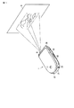
図1は、本発明の実施の形態が適用可能なプロジェクタ機能付きの携帯可能な電子機器の一例を示す。なお、以下に説明する実施形態では、携帯電話機を例に説明するが、映像を投影する機能を有し、投影光の光源としてLED(R,G,B)を用いる携帯可能機器であれば、例えばデジタルスチルカメラやプリンタ付きカメラ装置、もしくは携帯型音楽再生装置等であってもよく、また、任意の機器との間で、有線あるいは無線により、投影すべきデータの受け渡しを可能に構成された外部装置であってもよい。 FIG. 1 shows an example of a portable electronic device with a projector function to which an embodiment of the present invention can be applied. In the embodiment described below, a mobile phone will be described as an example. However, if the portable device has a function of projecting an image and uses LEDs (R, G, B) as a light source of projection light, For example, it may be a digital still camera, a camera device with a printer, a portable music playback device, or the like, and is configured to be able to exchange data to be projected with an arbitrary device by wire or wireless. It may be an external device.
プロジェクタ機能付き携帯電話装置(プロジェクタ装置)1は、例えばLCD(液晶)表示パネルまたはEL(自発光)パネルと撮像レンズを保持した表示ユニット10と本体ユニット20を有する。表示ユニット10と本体ユニット20は、接続部30により接続され、本体ユニット20に対して表示ユニット10が開放可能に形成されている。なお、接続部30またはその近傍の所定の位置には、プロジェクタ装置として利用する際に映像を投射する投射レンズ31が位置されている。投射レンズ31は、例えば表示ユニット10を閉じた状態で本体ユニット20側を平面(例えば机上等)に置いた場合に、投射像が概ね水平となるように、本体ユニット20に対する相対位置が決められている。従って、図2を用いて後段に説明するが、投射すべき画像を選択し、その画像を投射した以降は、表示ユニット10を閉じた状態で、例えば机上に置くことができ、その場合スクリーンSに投射される投射画像に対して外乱となることのある表示ユニット10側の映像をユーザの視野から排除することができる。
A mobile phone device (projector device) 1 with a projector function includes, for example, a
表示ユニット10には、静止画あるいは動画を撮影する際に、画像情報を取り込む撮像レンズ11が、設けられている。撮像レンズ11は、撮像対象を撮像しようとするユーザが、本体ユニット20に対して表示ユニット10を所定角度開放した際に、ユーザが本体ユニット20を支持した状態において、撮像対象に対して対向する。
The
本体ユニット20の所定位置には、外部装置との接続及び情報の受け渡しに用いられるコネクタや本体ユニット20に対して着脱可能なカード状のメモリ部材を格納するカードスロットが収納されている外部接続部21が設けられている。外部接続部21の近傍の所定の位置には、図示しない充電用電源装置あるいは外部バッテリ装置から電力が供給可能な給電ターミナル22が設けられている。
An external connection portion in which a card slot for storing a connector used for connection with an external device and information exchange and a card-like memory member that can be attached to and detached from the
図2は、図1に示したプロジェクタ装置(携帯電話機)において、投射画像を選択し、投射する際の本体ユニット側の操作と投射画像との関係を模式的に示す。なお、以下に説明する各要素において、「モジュール」と呼称する要素は、ハードウエアで実現するものであってもよいし、CPU(マイクロコンピュータ)等を用いて、ソフトウエアで実現するものであってもよい。 FIG. 2 schematically shows the relationship between the operation on the main unit side and the projected image when a projected image is selected and projected in the projector device (mobile phone) shown in FIG. In each element described below, an element called “module” may be realized by hardware, or may be realized by software using a CPU (microcomputer) or the like. May be.
表示ユニット10の本体ユニット20側に位置する面には、通話先または着信時の相手先の電話番号、データ送信先または送信元のアドレス、編集中もしくは再生中の文字情報または画像情報等が表示可能な表示部12、音声による通話や音楽データの再生に利用されるスピーカ13が設けられている。
On the surface located on the
本体ユニット20には、数値または文字情報の入力に利用される入力部23と音声による通話に利用されるマイクロホン24が、設けられている。なお、入力部23には、詳述しないが、例えば相手先電話番号や数字データの入力に利用される数値(ダイヤル)キー、送信キー、終了キー、電源キー、音量調節キー、モード指定キー等の、さまざまな機能の設定や動作状態の特定に利用されるさまざまな設定キーが設けられている。また、入力部23のうちの多機能キー23a,23b,23cは、例えば表示ユニット10の表示部12の所定の位置に表示されるGUI(Graphical User Interface)に対応して、選択/戻る、スクロール/切り替え、決定等のコマンドの入力に利用可能で、表示部12に表示される情報に対応してさまざまな操作入力が可能である。
The
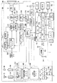
図3は、図1および図2に示した携帯端末装置(プロジェクタ装置)のハードの構成の一例を示す。 FIG. 3 shows an example of a hardware configuration of the portable terminal device (projector device) shown in FIGS. 1 and 2.
通信部101は、アンテナ共用器(DUP)102、受信回路(RX)103、中間周波数用シンセサイザ(SYN)104、送信回路(TX)105、及びCDMA信号処理部106、他を含む。CDMA信号処理部106は、少なくとも、圧縮伸長処理部(以後コンパンダと称する)107とPCM(音声)符号処理部(以後PCMコーデックと称する)108と接続されている。
The
基地局から送信された無線信号は、アンテナで受信され、DUP102により受信回路(RX)103に入力される。受信回路103では、受信した無線信号と周波数シンセサイザ(SYN)104から出力された局部発振信号とがミキシングされ、中間周波信号に周波数変換(ダウンコンバート)される。
The radio signal transmitted from the base station is received by the antenna and input to the receiving circuit (RX) 103 by the
受信回路103からは、中間周波信号を直交復調した受信ベースバンド信号が出力される。また、周波数シンセサイザ104から発生される局部発振信号の周波数は、以下に説明する主制御モジュール111からの制御信号SYCによって指示される。
The
受信ベースバンド信号は、CDMA信号処理部106に入力される。
The received baseband signal is input to CDMA
CDMA信号処理部106は、RAKE受信機を備える。
The CDMA
RAKE受信機では、受信ベースバンド信号に含まれる複数のパスが、それぞれ拡散符号により、逆拡散処理される。逆拡散処理された各パスの信号は、位相を合わされたのち合成される。この結果、所定の伝送フォーマットの受信パケットデータが得られる。 In the RAKE receiver, a plurality of paths included in the received baseband signal are each subjected to despreading processing using spreading codes. The signals of the paths subjected to the despreading process are combined after being matched in phase. As a result, received packet data in a predetermined transmission format is obtained.
受信パケットデータは、圧縮伸長処理部(以後コンパンダと称する)107に入力される。コンパンダ107は、図示しない多重分離部を含み、CDMA信号処理部106から出力された受信パケットデータが、多重分離部により、メディアデータ(情報の種類)ごとに分離され、メディアデータごとに、復号される。例えば、受信パケットデータにオーディオデータが含まれている場合、オーディオデータは、図示しないスピーチコーデックにより復号される。受信パケットデータにビデオデータが含まれていれば、ビデオデータは、図示しないビデオコーデックにより復号される。
The received packet data is input to a compression / decompression processing unit (hereinafter referred to as a compander) 107. The
コンパンダ107を介して復号されたテジタルオーディオ信号は、PCM(音声)符号処理部(以後PCMコーデックと称する)108へ、テジタルビデオ信号は、主制御モジュール111へそれぞれ入力される。なお、受信パケットデータに、メール等のテキストデータが含まれている場合には、テキストデータは、主制御モジュール111を通じて記憶部113に保存される。
The digital audio signal decoded via the
コンパンダ107から出力されたテジタルオーディオ信号は、PCMコーデック108でPCM復号され、アナログオーディオ信号として受話増幅器109に出力される。受話増幅器109に入力されたオーディオ信号は、所定レベルまで増幅されたのちスピーカ11に出力される。従って、スピーカ11からは、音声あるいは再生された音楽が出力される。
The digital audio signal output from the
コンパンダ107から出力されたデジタルビデオ信号は、後段に説明するビデオRAM(SDRAM)すなわちワークメモリ129を用いて、表示部12のLCD(Liquid Crystal Devise)パネルによる表示に適した信号形式に変換され、所定のタイミングでLCDパネルに転送される。これにより、LCDパネルには、図示しないLCD駆動回路を介して入力される映像信号に従って、画像が表示される。
The digital video signal output from the
メール等のテキストデータは、入力部23から入力される(ユーザの)指示に基づいて所定のタイミングで記憶部113から呼び出され、図示しないコード変換部により、表示すべき文字情報や記号等に対応した符号列に変換され、必要に応じてワークメモリ129で再生された映像と重ね合わせられ、LCDパネルが表示すべき情報としてLCDパネルに供給される。これにより、LCDパネルには、図示しないLCD駆動回路を介して入力される信号に従って、映像(動画あるいは静止画)ならびに文字や記号等が表示される。
Text data such as e-mail is called from the
なお、例えば留守番モードが設定されている場合には、主制御モジュール111の制御により、コンパンダ107において復号処理される前の段階のオーディオデータとビデオデータが記憶部113内の、例えば留守記録エリアに記憶される。
For example, when the answering machine mode is set, the audio data and the video data at the stage before being decoded by the
一方、マイクロホン24に入力された利用者の音声は、送話増幅器110により適正レベルまで増幅されたのち、PCMコーデック108にてPCM符号に符号化され、テジタルオーディオ信号として、コンパンダ107に入力される。また、後段に説明するカメラ機構により撮像された映像すなわち動画または静止画であるビデオ信号は、主制御モジュール111により、画像処理モジュール127でデジタル処理され、コンパンダ107に入力される。なお、主制御モジュール111において作成されたメール等のテキストデータも、主制御モジュール111を経由してコンパンダ107に入力される。
On the other hand, the user's voice input to the
コンパンダ107では、PCMコーデック108から入力されるデジタルオーディオ信号について、入力音声のエネルギー量が検出され、この検出結果に基づいて、送信データレートが決定される。決定された送信データレートに基づいて、デジタルオーディオ信号が送信データレートに応じたフォーマットの信号に符号化される。このようにして、送信用オーディオデータが生成される。また、コンパンダ107では、主制御モジュール111から出力されたデジタルビデオ信号が符号化され、ビデオデータが生成される。
The
音声データおよび画像データは、コンパンダ107の図示しない多重分離部により所定の伝送フォーマットに従いパケット化される。パケット化された送信パケットデータは、CDMA信号処理部106へ出力される。メール等のテキストデータも、同様にパケット化され、送信パケットデータに多重化される。
Audio data and image data are packetized according to a predetermined transmission format by a demultiplexing unit (not shown) of the
CDMA信号処理部106では、コンパンダ107から出力された送信パケットデータが送信チャネルに割り当てられた拡散符号を用いてスペクトラム拡散処理され、その出力信号が送信回路(TX)105へ出力される。
In the CDMA
送信回路105では、CDMA信号処理部106においてスペクトラム拡散された信号が、例えばQPSK方式のデジタル変調方式により変調される。変調された送信信号は、周波数シンセサイザ104から発生される局部発振信号と合成され、所定周波数の空間波すなわち無線信号に周波数変換される。
In the
送信回路105から空間波として出力される無線信号は、送信に先だって主制御モジュール111により指示される送信電力レベルとなるように(送信回路105において)、高周波増幅される。
The radio signal output as a spatial wave from the
増幅された無線信号すなわち高周波信号は、アンテナ共用器102を経由してアンテナに供給され、基地局へ向けて送信される。
The amplified radio signal, that is, a high-frequency signal is supplied to the antenna via the
なお、上述した一連の動作あるいはデータの記憶および保持に利用される電力は、図1および図2により前に説明した給電ターミナル22を経由して、予め図示しない商用電源または外部バッテリ装置から供給され、バッテリ114に保持されている。また、動作時あるいは必要に応じて、バッテリ114に保持されている電力が、電源回路115により所定の動作電源電圧Vccとして、携帯電話装置1の各部に供給される。
Note that the power used for the series of operations or data storage and retention described above is supplied in advance from a commercial power source or an external battery device (not shown) via the
主制御モジュール111はまた、上述した一連の動作あるいはデータの記憶および保持に利用されるCPU(Central Processing Unit)111aと接続されたI/Oポート(入出力部)111bを有し、図4により以下に説明するが、図2に示した外部接続部21のコネクタ(インタフェース)121と接続されることにより、サービスシステム(管理者側ホスト装置)との間の信号の受け渡しが可能である。なお、I/Oポート111bと接続されたコネクタ121には、ユーザが所有するパーソナルコンピュータや任意の装置に設けられているモデム等と接続された場合に、空間波による通信が可能に、詳述しないプロトコルに従った入出力向けの信号の割り当てが可能である。
The
CPU111aにはまた、外部インタフェース111cおよびUSB(Universal Serial Bus)ポート111dが接続されている。
An
外部インタフェース111cには、広く普及しているカード状の記憶媒体(半導体メモリ)、例えばmicroSDカード(登録商標)Mとの間でデータの受け渡しが可能なカードスロット131が接続されている。
The
カードスロット131は、microSDカードMを経由して、後段に説明するカメラ機構により撮像(取得)した静止画や動画、もしくは通信により入手(ダウンロード)した画像データ等を携帯電話装置1とは別の再生装置やパーソナルコンピュータ等に移動させるために利用される。また、microSDカードMにより、音楽データ等がデジタル化された符号情報や予め用意された画像情報を携帯電話装置1に移動させて、携帯電話装置1により音楽や画像を再生することができる。
The
USBポート111dには、USBコネクタ123が接続され、今日広く普及しているさまざまな外部機器、例えば外部記憶装置や携帯型音楽プレーヤ、等が接続可能である。もちろん、USB接続が可能なレコーダ装置等も接続可能であり、映像(動画)等も入力可能である。
A
撮像レンズ11により光の明暗および色の情報としてCMOSセンサ25に入力された撮像対象の画像情報は、入力画像処理モジュール125により、ホワイトバランス、入力γ特性、カラーバランス、等が最適化され、画像処理モジュール127を経由してワークメモリ129に、一旦保存される。ワークメモリ129に保持された撮像画像に対応する画像データは、ユーザによる保存操作があった場合、記憶部113に格納される。なお、そのまま添付画像として送信される場合は、上述のようにパケット化され、送信手続きに従い、基地局に向けて送信される。
The image information of the imaging target input to the
プロジェクタモジュール201は、ワークメモリ(SDRAM)129から供給される映像信号と主制御モジュール111から供給される同期信号(SYC)は、信号処理モジュール211とプロジェクタ制御モジュール213に、入力される。なお、プロジェクタモジュール201は、携帯電話装置1に組み込まれることを前提として、最終的な画像光を生成する画像形成モジュールとして、DMD(登録商標)=(Digital Micro mirror Device,デジタルマイクロミラーデバイス)素子215により、照明光(R(赤),G(緑),B(青)の3要素のそれぞれ)を映像信号で空間変調して、投射画像(出力画像)を得るもので、照明光の光源として、照明用LED217を用いる。照明用LED217としては、R,G,Bの光を出力するLEDチップが一体に形成された1パッケージタイプを用いてもよいし、図4により後段に説明するが、色ごとに独立したLED−R(421)、LED−G(422)、LED−B(423)からの個々の出力光(R,G,B)を、図4により後段に説明する投射光学系411により重ね合わせることによっても実現できる。
In the
信号処理モジュール211により、例えば解像度変換等のDMD表示のために画像処理された映像信号、すなわち投射用画像信号は、画角変換モジュール212により画角変換され、駆動回路(DMD)214に供給される。
The image signal processed for DMD display such as resolution conversion by the signal processing module 211, that is, the image signal for projection is converted into an angle of view by the angle of
駆動回路(DMD)214は、DMD素子215の個々のミラーの動作を制御するとともに、照明用LED217の個々のLED素子またはチップがR,G,Bのそれぞれの色の光を出力すべきタイミングに合わせて、個々のLED素子またはチップが所定強度の光を出力するよう、電流制御モジュール(レーザ駆動回路)216に、各LED素子またはチップに供給すべき電流値を、指示する。
The drive circuit (DMD) 214 controls the operation of the individual mirrors of the
DMD素子215は、TI(テキサスインスツルメント社)が提案するDLP(登録商標)すなわちデジタルライトプロセッシング方式により再生映像を形成する素子であり、R,G,Bのそれぞれの単位画像に対応して個々のミラーの角度を変化し、照明用LED217から同期して出力される個々の色の光を、投射レンズ31に向けて反射する。これにより、予め用意されるスクリーンS(あるいは投射位置として規定された壁等)に、投射対象である画像すなわちユーザが希望した動画または静止画が投射される。
The
照明用LED217の個々のLED素子またはチップあるいはLED素子またはチップを保持する基板もしくはパーケージの任意の位置には、LED217の温度をモニタする温度センサ218が用意されている。なお、複数のLED素子を用いる場合には、図4に一例を示すが、各LED素子のそれぞれに、温度センサ218−R,218−G,218−Bが独立に設けられることが好ましい。また、個々のLED素子またはLEDチップが単一の基板610にマウントされている場合には、温度センサ218は、図6に一例を示すように、基板の温度を検出するものであってもよい。またさらに、個々のLED素子またはLEDチップが共通のヒートシンク710に熱的に接続されている場合、温度センサ218は、図7に一例を示すように、ヒートシンクの温度を検出するものであってもよい。
A
温度センサ218の出力は、温度分析モジュール219において、現在温度として認識され、補正値算出モジュール220に供給される。
The output of the
補正値算出モジュール220は、温度分析モジュール219から供給される現在温度に従い、LED素子相互間の温度差、およびプロジェクタ装置としての色み(色再現性)を設定した温度(基準温度)に対する偏差等を分析し、その結果に応じ、補正値に見合った各LEDへの駆動電流の大きさすなわち電流制御値を設定し、電流制御モジュール216から各LED素子またはチップに供給される電流値を、補正する(光強度を色毎に温度補償する)。
The correction
なお、各LED素子またはチップは、図5に一例を示すが、基準温度(25℃)の出力を「1」としたとき、温度が下がるにつれて出力光強度が増加し、温度が上がるにつれて出力光強度が減少することが知られている。また、出力光強度の変化は、色み(出力光波長)の変化を引き起こすこともある。特に、色みの変化は、それぞれの光を重ね合わせた結果として再現される光の白さの程度に影響を及ぼす。 FIG. 5 shows an example of each LED element or chip. When the output of the reference temperature (25 ° C.) is “1”, the output light intensity increases as the temperature decreases, and the output light increases as the temperature increases. It is known that the strength decreases. In addition, a change in output light intensity may cause a change in color (output light wavelength). In particular, the color change affects the degree of whiteness of light reproduced as a result of superimposing the respective lights.
多くの場合、照明光の出力時間と温度上昇は、概ね比例するため、電流制御モジュール216から各LED素子またはチップに供給される電流値は、次第に増加される。反面、気温が低い場合の投射開始時(駆動初期時)には、電流制御モジュール216から各LED素子またはチップに供給される電流値は、上述の基準温度に対する電流値に比較して、抑制(減少)される。なお、同じ色の光を出力するLED素子であっても個体差があることが知られており、プロジェクタ装置(携帯電話装置)1毎に、かつ組み込まれる照明用LED217の各LED素子またはチップ毎に、上述した温度補正を実施することはいうまでもない。
In many cases, the output time of the illumination light and the temperature increase are approximately proportional, so that the current value supplied from the
なお、プロジェクタ装置(携帯電話装置)1がテレビジョンチューナ(TV受信モジュール)を有する場合には、DMD素子215(プロジェクタモジュール201)を介して投射可能な映像として、テレビジョン放送のさまざまな番組も含まれることはいうまでもない。 When the projector device (mobile phone device) 1 has a television tuner (TV reception module), various television broadcast programs are also available as images that can be projected through the DMD element 215 (projector module 201). Needless to say, it is included.
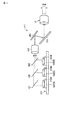
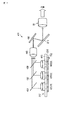
図4は、照明用LEDがR,G,Bの独立したLED素子からなる場合、それぞれのLED素子が出力する光をDMD素子に案内する投射光学系の構成の一例を示す。 FIG. 4 shows an example of the configuration of a projection optical system that guides the light output from each LED element to the DMD element when the illumination LED is composed of R, G, and B independent LED elements.
図4から明らかなように、照明用LED217の個々のLED、すなわちR光を出力するLED−R421、G光を出力するLED−G422、B光を出力するLED−B423のそれぞれから出力される光は、それぞれ透過光(波長)特性の異なるダイクロイックミラー431,432,433により同一光路に実質的に重ね合わせられ、ライトパイプ440を介して波面すなわち軸上と周辺部(光軸と直交する方向の所定範囲内の領域)の明るさ及び色み(ホワイトバランスおよびカラーバランス)が均一化され、ミラー450によりDMD素子215に照射される。
As is apparent from FIG. 4, light output from each of the
なお、ミラー450は、照明用LED217とDMD素子215との配列を最適化することにより、省略できる場合がある。
In some cases, the
以下、照明用LEDの各LED素子またはチップ毎に供給する駆動電流の大きさを設定する例を説明する。 Hereinafter, an example of setting the magnitude of the drive current supplied for each LED element or chip of the illumination LED will be described.
プロジェクタモジュール201による任意の画像の投射が要求されると、ユーザによる投射対象の画像(動画または静止画)もしくはテキストデータが入力部23及び表示部12のLCDパネルに表示されるGUIにより選択された時点で、温度センサ218が検出した周囲温度が取り込まれ、周囲温度が基準温度に対して、高いか低いかが判断される。なお、周囲温度の検出は、ユーザによる投射開始が指示された時点であってもよい。また、周期的に行っても良い。
When projection of an arbitrary image by the
照明用LED217の周囲温度が基準温度よりも低い場合、個々のLED素子またはチップに用意される温度補償曲線に従い、基準温度に比較して小さい(少ない)所定値に、投射開始時の駆動電流の大きさが、設定される。なお、照明用LED217の周囲温度が基準温度よりも高い場合、個々のLED素子またはチップに用意される温度補償曲線に従い、基準温度に比較して大きい(多い)所定値に、投射開始時の駆動電流の大きさが、設定される。
When the ambient temperature of the
以下、任意の画像の投射、あるいは投射対象となる画像の変更と投射が継続されることで、所定時間毎に、照明用LED217の周囲温度が検出され、検出された温度に従い、電流供給モジュール216からLED217の個々のLED素子またはチップのそれぞれに供給されるレーザ駆動電流の大きさが変更される。なお、R,G,Bの3つの光を重ね合わせて光を得る場合、現状では発光効率が最も低い青(B)のLED素子またはLEDチップの近傍の温度を検知し、残りのLED素子(R,G)またはLEDチップについては、青(B)と補正を共通化することも可能である。
Hereinafter, by projecting an arbitrary image or changing and projecting an image to be projected, the ambient temperature of the
図8は、図1〜図3に示したプロジェクタ(携帯電話)において、光源すなわちLEDの点灯開始時に、LEDまたはその周囲の温度が所定温度よりも低い場合において、発光輝度を変化する例を示す。 FIG. 8 shows an example in which the luminance of light emitted from the projector (mobile phone) shown in FIGS. 1 to 3 changes when the light source, that is, the LED starts lighting, when the temperature of the LED or its surroundings is lower than a predetermined temperature. .
図8から明らかなように、LEDすなわち白色光源は、通常の輝度で点灯を開始した場合、輝度Aで示すような温度上昇を示す。すなわち、LED光源の寿命を考慮した場合、LEDの温度を一定以下にする必要があり、その温度をTとすると、通常は温度T以下で飽和するような輝度で使い続けることになる。 As is apparent from FIG. 8, the LED, that is, the white light source, shows a temperature rise as indicated by luminance A when lighting is started at normal luminance. That is, when considering the lifetime of the LED light source, the temperature of the LED needs to be kept below a certain level. When the temperature is T, the LED light source is normally used at a brightness that saturates below the temperature T.
これに対し、プロジェクタ(携帯電話)の使用開始直後等、LED点灯直後であれば、LED光源の温度はTよりも低いといえるため、その場合には、通常の輝度よりも高い輝度Bに設定し、投影映像を明るくすることができる(投射映像の輝度を高めることができる)。 On the other hand, since the temperature of the LED light source is lower than T if the LED is turned on, such as immediately after the start of use of the projector (cell phone), in that case, the luminance B is set to a luminance B higher than the normal luminance. Thus, the projected image can be brightened (the luminance of the projected image can be increased).
もちろん、そのまま輝度Bで使用し続けると、温度Tをこえてしまうため、温度がTに達した段階で、輝度Aに設定することが必要である。 Of course, if it continues to be used at the luminance B as it is, the temperature T will be exceeded, so it is necessary to set the luminance A when the temperature reaches T.
なお、点灯に際し、その直前まで使用していた(一旦オフした直後に再び点灯した)等の点灯開始時にLEDの温度が十分に低いとはいえない場合を考慮し、図3に示した温度センサー218の出力に基づき、温度がT付近の場合は、初めから輝度Aで点灯させる。 In consideration of the case where the temperature of the LED is not sufficiently low at the start of lighting, such as that it was used until immediately before lighting (lighted again immediately after being turned off), etc., the temperature sensor shown in FIG. Based on the output of 218, when the temperature is near T, the light is lit with luminance A from the beginning.
また、温度センサー218の出力は、定期的にモニタし、検出温度が温度Tに達した時点で、LEDに供給する駆動電流の大きさ(電力)を通常に戻すものとする。なお、温度Tについては、LED毎に異なる場合が多いため、図4に示したように、個々のLEDの温度を検出し、いずれかのセンサーが検出した温度が温度Tに達した時点で、駆動電流の大きさを輝度Aに戻すことが好ましい。また、各LEDの温度を直接測ることに限らず、図6あるいは図7に示したように、LEDの温度と相関関係が取れれば、間接的な部分で検出した温度を代用してもよいことはいうまでもない。
Further, the output of the
なお、主制御モジュール111のCPU111aのファームウェアとして、輝度Bによる点灯開始を選択可能とするモードを持たせてもよい。例えば、図9に示すように、モード設定機能(画面)を用意し、ユーザからの選択に従い、低温度からの点灯時に高輝度で点灯するか否かを予め選択することもできる。
It should be noted that the firmware of the
より詳細には、図9に示すように、設定モードが起動(開始)されると、モードの選択により、「低温時、LEDの点灯時輝度をアップしますか(輝度アップモード選択画面)?」が表示される(ブロック[11])。 More specifically, as shown in FIG. 9, when the setting mode is activated (started), the mode is selected and “Will the brightness increase when the LED is lit at low temperatures (brightness increase mode selection screen)? Is displayed (block [11]).
ブロック[11]において、例えば「YES」が選択されると、『輝度アップ設定(低温時、高輝度で点灯開始)』が設定される(ブロック[12])。 For example, when “YES” is selected in the block [11], “brightness up setting (lighting start at high temperature at low temperature)” is set (block [12]).
これに対し、ブロック[11]、「NO」が選択されると、『輝度アップ非設定(低温時も通常起動)』が設定される(ブロック[13])。 On the other hand, when the block [11], “NO” is selected, “brightness not set (normal start even at low temperature)” is set (block [13]).
図10は、図8に示した温度特性を用いて、起動時に輝度を高める「輝度アップモード」を実行しない場合を設定する方法の一例を示す。 FIG. 10 shows an example of a method for setting a case where the “brightness up mode” for increasing the brightness at the time of activation is not executed using the temperature characteristic shown in FIG.
はじめに、LED点灯前の温度が、図8に示した「しきい値“T”」よりも低いことがチェックされる(ブロック[21])。また、温度が「しきい値“T”」に、既に達している場合(ブロック[21]−NO)には、「通常輝度モード」で点灯される(ブロック[25])。 First, it is checked that the temperature before the LED is lit is lower than the “threshold“ T ”” shown in FIG. 8 (block [21]). When the temperature has already reached the “threshold“ T ”” (block [21] -NO), the light is turned on in the “normal luminance mode” (block [25]).
なお、点灯前のLED(光源)またはその近傍の温度が「しきい値“T”」よりも低い場合であっても、図9で説明した「輝度アップモード」が選択されていない場合(ブロック[22]−NO)には、「通常輝度モード」で点灯される(ブロック[25])。 Even when the LED (light source) before lighting or the temperature in the vicinity thereof is lower than the “threshold“ T ””, the “brightness up mode” described in FIG. 9 is not selected (block) [22] -NO) is lit in the “normal luminance mode” (block [25]).
一方、多くの場合、静止画については、比較的低輝度であっても高い視認性が得られることから、「しきい値“T”」よりも温度が低く、「輝度アップモード」が選択(設定)されている場合においても、「通常輝度モード」を優先するものとする。この場合、消費電力が低減可能であること、LEDの寿命を維持できること等のメリットが得られる。なお、静止画についても「輝度アップモード」を選択可能とすることも可能であることはいうまでもない(例えば、図10において、ブロック[23]が省略されている手順を考えればよい)。 On the other hand, in many cases, since still images can be obtained with high visibility even at relatively low brightness, the temperature is lower than “threshold“ T ”” and “brightness up mode” is selected ( Even in the case of setting, the “normal luminance mode” has priority. In this case, it is possible to obtain merits such as that power consumption can be reduced and that the lifetime of the LED can be maintained. Needless to say, the “brightness up mode” can also be selected for a still image (for example, a procedure in which the block [23] is omitted in FIG. 10 may be considered).
図11は、図8に示した温度特性を用いて、起動時に輝度を高める「輝度アップモード」により動作を開始したプロジェクタ(携帯電話)において、「輝度アップモード」から「通常輝度モード」に移行する手順の一例を示す。 FIG. 11 shows a transition from “brightness up mode” to “normal brightness mode” in a projector (mobile phone) that has started operation in the “brightness up mode” that increases the brightness at startup using the temperature characteristics shown in FIG. An example of the procedure is shown.
はじめに、LED点灯前の温度が、図8に示した「しきい値“T”」よりも低いことがチェックされる(ブロック[31])。すなわち、直前まで、映像が再生されていた場合等、既にLEDの温度が「しきい値“T”」に、既に達している場合(ブロック[31]−NO)には、「通常輝度モード」で点灯される(ブロック[36])。 First, it is checked that the temperature before the LED is lit is lower than the “threshold“ T ”” shown in FIG. 8 (block [31]). In other words, when the video has been reproduced until immediately before, for example, when the temperature of the LED has already reached the “threshold“ T ”” (block [31] -NO), the “normal luminance mode” (Block [36]).
LED(光源)に所定の駆動電流(電力)が供給されると、所定時間経過後に、LEDまたはその近傍の温度が、「しきい値“T”」よりもn(nは正の数)段低い温度であるか否かがチェックされ、「輝度アップモード」を継続可能か否かが判断される(ブロック[32])。 When a predetermined drive current (electric power) is supplied to the LED (light source), the temperature of the LED or its vicinity is n (n is a positive number) stages from the “threshold value“ T ”after a predetermined time has elapsed. It is checked whether or not the temperature is low, and it is determined whether or not the “brightness up mode” can be continued (block [32]).
ブロック[32]において、LEDまたはその近傍の温度が「しきい値“T”」に達したことが検知された場合(ブロック[32]−NO)、「通常輝度モード」が設定される(ブロック[36])。 In block [32], when it is detected that the temperature of the LED or its vicinity has reached “threshold“ T ”” (block [32] -NO), “normal luminance mode” is set (block [36]).
ブロック[32]において、LEDまたはその近傍の温度が「しきい値“T”」に達するまでに余裕があることが検知された場合(ブロック[32]−YES)、LEDに供給される駆動電流(電力)が1段分、低下される(ブロック[33])。なお、駆動電流の変化量すなわち「輝度アップモード」と「通常輝度モード」との間に設定可能な駆動電流の段数は、LEDの出力やバッテリーの容量、「輝度アップモード」から「通常輝度モード」に移行すべき時間等に基づいて、個別に設定されることはいうまでもない。 In block [32], when it is detected that there is room before the temperature of the LED or its vicinity reaches the “threshold value“ T ”” (block [32] —YES), the drive current supplied to the LED (Power) is reduced by one stage (block [33]). Note that the amount of change in drive current, that is, the number of drive current stages that can be set between the “brightness up mode” and the “normal brightness mode” depends on the LED output, the battery capacity, and the “brightness up mode” to “normal brightness mode”. Needless to say, it is set individually based on the time to be shifted to.
ブロック[33]において、LEDに供給される駆動電流(電力)が1段分低下されると、タイマー機能により所定時間がカウントされる。すなわち、「輝度アップモード」と「通常輝度モード」との間に設定される任意の大きさの駆動電流がLEDに供給されてからの経過時間が計測され、次の大きさの駆動電流による駆動に移行される(ブロック[34])。 In block [33], when the drive current (power) supplied to the LED is reduced by one stage, a predetermined time is counted by the timer function. In other words, the elapsed time after the drive current of an arbitrary magnitude set between the “brightness up mode” and the “normal brightness mode” is supplied to the LED is measured, and the drive with the drive current of the next magnitude is performed. (Block [34]).
ブロック[34]において、1段分の所定時間が経過すると、LEDまたはその近傍の温度が「しきい値“T”」に達したか否か、すなわち「輝度アップモード」を継続できるか否かがチェックされる(ブロック[35])。 In block [34], whether or not the temperature of the LED or the vicinity thereof has reached the “threshold“ T ””, that is, whether or not the “brightness up mode” can be continued when a predetermined time for one stage has elapsed. Is checked (block [35]).
ブロック[35]において、「輝度アップモード」が維持可能であることが検知された場合([35]−NO)、ブロック[32]〜ブロック[35]が繰り返される。なお、例えば、ブロック[33]とブロック[34]は、その実行順が逆であってもよいことはいうまでもない。 In block [35], when it is detected that the “brightness up mode” can be maintained ([35] -NO), block [32] to block [35] are repeated. For example, the execution order of the block [33] and the block [34] may be reversed.
以下、ブロック[35]において、「輝度アップモード」を終了すべき温度に達したことが検知された場合([35]−YES)、「通常輝度モード」へ移行され、LEDは、通常輝度で点灯される(ブロック[36])。 Hereinafter, in block [35], when it is detected that the temperature to end the “brightness up mode” has been reached ([35] -YES), the process proceeds to the “normal brightness mode”, and the LED is in normal brightness. Illuminated (block [36]).
このように、図8に示した輝度Bで点灯したLEDの輝度を、「しきい値“T”」において輝度Aになるよう、一定時間ごとにLEDに供給する駆動電流の大きさを減少することで、輝度アップ期間が終了して通常輝度による点灯へ移行する際に、明るさの変化が急峻となることが防止できる。これにより、映像を投影して再生する利用者は、映像の光量(明るさ)が不自然に変化することのない再生映像を見ることができる。また、図10により説明したが、静止画については、LEDまたはその近傍の温度に拘わらず、「輝度アップモード」を適用しないことも選択可能であり、その場合、ファイルの種類を特定するブロックが、例えば、ブロック[32]〜ブロック[34]の任意の区間に用意される。 As described above, the magnitude of the drive current supplied to the LED is decreased at regular intervals so that the brightness of the LED lit at the brightness B shown in FIG. 8 becomes the brightness A at the “threshold value“ T ””. Thus, it is possible to prevent a change in brightness from becoming steep when the luminance up period ends and the lighting shifts to the normal luminance. Accordingly, a user who projects and reproduces an image can view a reproduced image in which the amount of light (brightness) of the image does not change unnaturally. Further, as described with reference to FIG. 10, it is possible to select not to apply the “brightness up mode” for a still image regardless of the temperature of the LED or the vicinity thereof. In this case, there is a block for specifying the file type. For example, it is prepared in an arbitrary section of block [32] to block [34].
以上説明したように、この発明の実施の一形態を適用することで、温度の変化すなわち出力光強度の変動により、投射画像の色みや軸上と周辺部とで強度が変動することが抑止され、色再現性の高い投射画像を得ることができる。 As described above, by applying the embodiment of the present invention, it is possible to prevent the intensity of the projected image from changing between the color and the on-axis and the peripheral part due to a change in temperature, that is, a change in output light intensity. A projection image with high color reproducibility can be obtained.
また、投射像の明るさすなわちスクリーン上の照度を測定する必要がなくなり、装置の大きさ及びコストを低減できる。 Further, it is not necessary to measure the brightness of the projected image, that is, the illuminance on the screen, and the size and cost of the apparatus can be reduced.
さらに、DMD素子を用いたDLP方式により形成される再生画像を投射する際、LED光源を用いたことにより、例えば携帯電話装置内に解像度の高い映像を再生可能なプロジェクタ装置を一体に組み込むことができ、例えばカメラ機能により撮像した動画や静止画をその場で拡大投影して、複数のユーザで同時に再生映像を楽しむことができる。 Furthermore, when projecting a reconstructed image formed by the DLP method using a DMD element, an LED light source is used so that a projector device capable of replaying a high-resolution video can be integrated in a mobile phone device, for example. For example, a moving image or a still image captured by the camera function can be enlarged and projected on the spot, and a plurality of users can simultaneously enjoy the reproduced video.
またさらに、携帯可能な電子機器に組み込まれた光源のLEDの点灯開始時に、LEDまたはその周囲の温度が所定温度よりも低い場合、所定時間の間、LED素子に供給する駆動電流の大きさを増大して発光時の輝度を高めることにより、表示(点灯)開始直後の映像の輝度を高めることができ、比較的短い時間に限って映像を投影(再生)する際に、明るい再生映像を得ることができる。 Furthermore, when the LED of the light source incorporated in the portable electronic device is turned on, if the temperature of the LED or its surroundings is lower than a predetermined temperature, the magnitude of the drive current supplied to the LED element for a predetermined time is set. By increasing the luminance at the time of light emission, the luminance of the video immediately after the start of display (lighting) can be increased, and a bright reproduced video is obtained when the video is projected (reproduced) only for a relatively short time. be able to.
なお、この発明は、上述した各実施の形態に限定されるものではなく、その実施の段階ではその要旨を逸脱しない範囲で種々な変形もしくは変更が可能である。また、各実施の形態は、可能な限り適宜組み合わせて、もしくは一部を削除して実施されてもよく、その場合は、組み合わせもしくは削除に起因したさまざまな効果が得られる。 In addition, this invention is not limited to each embodiment mentioned above, A various deformation | transformation or change is possible in the range which does not deviate from the summary in the stage of the implementation. In addition, the embodiments may be implemented by appropriately combining them as much as possible, or by deleting a part thereof. In that case, various effects resulting from the combination or deletion can be obtained.
1…携帯電話装置(プロジェクタ装置)、10…表示ユニット、11…撮像レンズ、12…LCDパネル(表示部)、20…本体ユニット、23…入力部、25…CMOSセンサ、31…投射レンズ、101…通信部、111…主制御モジュール(制御部)、113…記憶部、125…入力画像処理モジュール、127…画像処理モジュール、129…SDRAM(ワークメモリ)、201…プロジェクタモジュール、211…信号処理モジュール、212…画角変換モジュール、213…プロジェクタ制御モジュール、214…駆動回路(DMD駆動モジュール)、215…DMD(DLP)素子、216…電流制御モジュール(レーザ駆動回路)、217…照明用LED(光源)、218…温度センサ、219…温度分析モジュール、220…補正値算出モジュール、411…投射光学系、421…LED−R、422…LED−G、423…LED−B、431,432,433…ダイクロイックミラー。
DESCRIPTION OF
Claims (13)
前記光源が出力する色成分毎の光を、対応する色成分毎の画像情報に基づいて空間変調し、各色成分に対応する映像を生成する映像形成モジュールと、
前記光源が含む発光素子またはその近傍の温度を検出する温度検出モジュールと、
前記温度検出モジュールが検出する温度に基づいて前記光源が出力する色成分毎の光の強度を、個々に補正する光源駆動モジュールと、
前記映像形成モジュールが形成する画像をスクリーンに投射する投射光学系と、
を有することを特徴とするプロジェクタ装置。 A light source that outputs light;
A video forming module that spatially modulates light for each color component output from the light source based on image information for each corresponding color component, and generates a video corresponding to each color component;
A temperature detection module for detecting a temperature of a light emitting element included in the light source or the vicinity thereof; and
A light source driving module for individually correcting the intensity of light for each color component output from the light source based on the temperature detected by the temperature detection module;
A projection optical system that projects an image formed by the video forming module onto a screen;
A projector apparatus comprising:
取得した温度に基づいて、個々の単色光源が出力する光量を、単色光源毎に設定し、
投射される映像の色あいまたは明るさの少なくとも一方を設定する
ことにより投射映像の色または明るさの変動を抑制する方法。
ことを特徴とする映像表示方法。 Acquire the temperature of each or near multiple monochromatic light sources that output light,
Based on the acquired temperature, set the amount of light output by each single color light source for each single color light source,
Set at least one of color and brightness of the projected image
A method for suppressing variations in color or brightness of projected images.
A video display method characterized by the above.
前記光源が出力する色成分毎の光を、対応する色成分毎の画像情報に基づいて空間変調し、各色成分に対応する映像を生成する映像形成モジュールと、
前記光源が含む発光素子またはその近傍の温度を検出する温度検出モジュールと、
前記温度検出モジュールが検出する温度に基づいて前記光源が出力する色成分毎の光の強度を、個々に補正する光源駆動モジュールと、
前記映像形成モジュールが形成する画像をスクリーンに投射する投射光学系と、
を有することを特徴とする携帯電話装置。 A light source that outputs light;
A video forming module that spatially modulates light for each color component output from the light source based on image information for each corresponding color component, and generates a video corresponding to each color component;
A temperature detection module for detecting a temperature of a light emitting element included in the light source or the vicinity thereof; and
A light source driving module for individually correcting the intensity of light for each color component output from the light source based on the temperature detected by the temperature detection module;
A projection optical system that projects an image formed by the video forming module onto a screen;
A mobile phone device characterized by comprising:
前記光源からの光の光量と関連のある前記光源の温度を、前記光源またはその近傍で検出する温度検出モジュールと、
前記光源が出力する光を画像情報に基づいて空間変調し、映像を生成する映像形成モジュールと、
前記光源へ供給する駆動電流を、点灯開始から所定時間の間、前記温度検出モジュールが検出する温度に基づいて増大する光源駆動モジュールと、
前記映像形成モジュールが形成する画像をスクリーンに投射する投射光学系と、
を有することを特徴とするプロジェクタ装置。 A light source that outputs light;
A temperature detection module that detects the temperature of the light source related to the amount of light from the light source at or near the light source;
A video forming module that spatially modulates light output from the light source based on image information and generates a video;
A light source drive module that increases a drive current supplied to the light source based on a temperature detected by the temperature detection module for a predetermined time from the start of lighting;
A projection optical system that projects an image formed by the video forming module onto a screen;
A projector apparatus comprising:
取得した温度に基づき、駆動電流の供給の開始から所定期間の間、前記光源に供給する駆動電流の大きさを基準値に比較して増大し、
駆動電流の供給開始から所定時間が経過するまでの間に、基準値に比較して増大される程度を次第に減少させ、
投射される映像の明るさが投射開始直後に低下することを抑制する
ことを特徴とする映像表示方法。 Get the temperature of the light source that emits light or its vicinity,
Based on the acquired temperature, for a predetermined period from the start of supply of drive current, the magnitude of drive current supplied to the light source is increased compared to a reference value,
In the period from when the drive current starts to be supplied until a predetermined time elapses, the degree of increase is gradually reduced compared to the reference value,
An image display method characterized by suppressing a decrease in brightness of a projected image immediately after the start of projection.
Priority Applications (2)
| Application Number | Priority Date | Filing Date | Title |
|---|---|---|---|
| JP2009130587A JP2010191402A (en) | 2009-01-26 | 2009-05-29 | Projector, image display method, and mobile telephone |
| US12/689,865 US8322860B2 (en) | 2009-01-26 | 2010-01-19 | Projector apparatus and method of controlling the color fluctuation of the light |
Applications Claiming Priority (2)
| Application Number | Priority Date | Filing Date | Title |
|---|---|---|---|
| JP2009014561 | 2009-01-26 | ||
| JP2009130587A JP2010191402A (en) | 2009-01-26 | 2009-05-29 | Projector, image display method, and mobile telephone |
Publications (1)
| Publication Number | Publication Date |
|---|---|
| JP2010191402A true JP2010191402A (en) | 2010-09-02 |
Family
ID=42353907
Family Applications (1)
| Application Number | Title | Priority Date | Filing Date |
|---|---|---|---|
| JP2009130587A Pending JP2010191402A (en) | 2009-01-26 | 2009-05-29 | Projector, image display method, and mobile telephone |
Country Status (2)
| Country | Link |
|---|---|
| US (1) | US8322860B2 (en) |
| JP (1) | JP2010191402A (en) |
Cited By (2)
| Publication number | Priority date | Publication date | Assignee | Title |
|---|---|---|---|---|
| JP2018097221A (en) * | 2016-12-14 | 2018-06-21 | 株式会社ユニバーサルエンターテインメント | Game machine and device for game |
| JP2021101232A (en) * | 2019-10-23 | 2021-07-08 | 株式会社リコー | Image projection device |
Families Citing this family (8)
| Publication number | Priority date | Publication date | Assignee | Title |
|---|---|---|---|---|
| KR101619518B1 (en) * | 2009-06-11 | 2016-05-11 | 엘지이노텍 주식회사 | Projection system |
| JP5740822B2 (en) | 2010-03-04 | 2015-07-01 | ソニー株式会社 | Information processing apparatus, information processing method, and program |
| US8789954B1 (en) | 2010-06-09 | 2014-07-29 | Rockwell Collins, Inc. | Front projection display system for a vehicle |
| US9363461B1 (en) * | 2010-06-09 | 2016-06-07 | Rockwell Collins, Inc. | Rear projection display system for a vehicle |
| WO2012099034A1 (en) * | 2011-01-21 | 2012-07-26 | 株式会社ニコン | Focus position maintaining apparatus, and microscope |
| JP6897389B2 (en) * | 2017-07-25 | 2021-06-30 | 富士通株式会社 | Discrimination computer program, discriminating device and discriminating method, and communication system |
| CN107872663B (en) | 2017-12-25 | 2019-05-24 | Oppo广东移动通信有限公司 | Image processing method and device, computer readable storage medium and computer equipment |
| CN113093461B (en) * | 2021-04-12 | 2022-03-29 | 深圳市和天创科技有限公司 | Projector cooling method and system |
Citations (12)
| Publication number | Priority date | Publication date | Assignee | Title |
|---|---|---|---|---|
| JPS61140933A (en) * | 1984-12-13 | 1986-06-28 | Ricoh Co Ltd | Method for controlling lamp for illumination of original |
| JPH07296981A (en) * | 1994-04-27 | 1995-11-10 | Ushio Inc | Mercury lamp lighting method |
| JP2002333671A (en) * | 2001-05-07 | 2002-11-22 | Matsushita Electric Ind Co Ltd | Color reproducibility correction device for projector |
| JP2004226631A (en) * | 2003-01-22 | 2004-08-12 | Seiko Epson Corp | Projector and optical device |
| JP2005106974A (en) * | 2003-09-29 | 2005-04-21 | Seiko Epson Corp | Projector |
| JP2005208231A (en) * | 2004-01-21 | 2005-08-04 | Seiko Epson Corp | Light source device, apparatus and method for controlling light source device, and projector |
| JP2006154016A (en) * | 2004-11-26 | 2006-06-15 | Nikon Corp | Projector device |
| JP2007156438A (en) * | 2005-11-11 | 2007-06-21 | Matsushita Electric Ind Co Ltd | Display device |
| JP2008145486A (en) * | 2006-12-06 | 2008-06-26 | Seiko Epson Corp | Projector |
| JP2008177107A (en) * | 2007-01-22 | 2008-07-31 | Seiko Epson Corp | Light-emitting device, image forming apparatus, and driving method of light-emitting device |
| JP2008185924A (en) * | 2007-01-31 | 2008-08-14 | Olympus Corp | Illuminating apparatus and image projector |
| JP2008193054A (en) * | 2007-01-09 | 2008-08-21 | Seiko Epson Corp | Light source device, projector device, monitor device, and lighting device |
Family Cites Families (10)
| Publication number | Priority date | Publication date | Assignee | Title |
|---|---|---|---|---|
| JP3052318B2 (en) * | 1989-10-31 | 2000-06-12 | セイコーエプソン株式会社 | Projector and control method thereof |
| JP2002064223A (en) | 2000-08-16 | 2002-02-28 | Sony Corp | Drive circuit of semiconductor light-emitting diode |
| JP4524985B2 (en) | 2002-11-11 | 2010-08-18 | セイコーエプソン株式会社 | LIGHT CONTROL DEVICE, LIGHTING DEVICE, ITS CONTROL METHOD, AND PROJECTOR |
| TW566573U (en) * | 2003-04-09 | 2003-12-11 | Coretronic Corp | Color temperature adjustable projection apparatus |
| US7070284B2 (en) * | 2003-06-19 | 2006-07-04 | Marantz Japan, Inc. | Projector apparatus |
| JP4631370B2 (en) | 2004-09-21 | 2011-02-16 | 株式会社ニコン | Projector device, mobile phone, camera |
| ATE532330T1 (en) * | 2004-09-21 | 2011-11-15 | Nikon Corp | PROJECTOR SETUP, CELL PHONE AND CAMERA |
| JP2006223588A (en) * | 2005-02-17 | 2006-08-31 | Aruze Corp | Game machine, and method of controlling display of card in game machine |
| JP2007108205A (en) | 2005-10-11 | 2007-04-26 | Seiko Epson Corp | Maintenance system of image display apparatus |
| JP2007147870A (en) | 2005-11-25 | 2007-06-14 | Sharp Corp | Display device |
-
2009
- 2009-05-29 JP JP2009130587A patent/JP2010191402A/en active Pending
-
2010
- 2010-01-19 US US12/689,865 patent/US8322860B2/en not_active Expired - Fee Related
Patent Citations (12)
| Publication number | Priority date | Publication date | Assignee | Title |
|---|---|---|---|---|
| JPS61140933A (en) * | 1984-12-13 | 1986-06-28 | Ricoh Co Ltd | Method for controlling lamp for illumination of original |
| JPH07296981A (en) * | 1994-04-27 | 1995-11-10 | Ushio Inc | Mercury lamp lighting method |
| JP2002333671A (en) * | 2001-05-07 | 2002-11-22 | Matsushita Electric Ind Co Ltd | Color reproducibility correction device for projector |
| JP2004226631A (en) * | 2003-01-22 | 2004-08-12 | Seiko Epson Corp | Projector and optical device |
| JP2005106974A (en) * | 2003-09-29 | 2005-04-21 | Seiko Epson Corp | Projector |
| JP2005208231A (en) * | 2004-01-21 | 2005-08-04 | Seiko Epson Corp | Light source device, apparatus and method for controlling light source device, and projector |
| JP2006154016A (en) * | 2004-11-26 | 2006-06-15 | Nikon Corp | Projector device |
| JP2007156438A (en) * | 2005-11-11 | 2007-06-21 | Matsushita Electric Ind Co Ltd | Display device |
| JP2008145486A (en) * | 2006-12-06 | 2008-06-26 | Seiko Epson Corp | Projector |
| JP2008193054A (en) * | 2007-01-09 | 2008-08-21 | Seiko Epson Corp | Light source device, projector device, monitor device, and lighting device |
| JP2008177107A (en) * | 2007-01-22 | 2008-07-31 | Seiko Epson Corp | Light-emitting device, image forming apparatus, and driving method of light-emitting device |
| JP2008185924A (en) * | 2007-01-31 | 2008-08-14 | Olympus Corp | Illuminating apparatus and image projector |
Cited By (3)
| Publication number | Priority date | Publication date | Assignee | Title |
|---|---|---|---|---|
| JP2018097221A (en) * | 2016-12-14 | 2018-06-21 | 株式会社ユニバーサルエンターテインメント | Game machine and device for game |
| JP2021101232A (en) * | 2019-10-23 | 2021-07-08 | 株式会社リコー | Image projection device |
| JP7521302B2 (en) | 2019-10-23 | 2024-07-24 | 株式会社リコー | Image Projection Device |
Also Published As
| Publication number | Publication date |
|---|---|
| US20100188588A1 (en) | 2010-07-29 |
| US8322860B2 (en) | 2012-12-04 |
Similar Documents
| Publication | Publication Date | Title |
|---|---|---|
| JP2010191402A (en) | Projector, image display method, and mobile telephone | |
| JP4254672B2 (en) | Portable information equipment | |
| JP5944093B2 (en) | Portable electronic devices | |
| WO2010150891A1 (en) | Portable electronic device | |
| WO2013140958A1 (en) | Image display device, photography device, image display system and method | |
| JP2010170048A (en) | Projector device | |
| JP2014059714A (en) | Display device, display system, and method for controlling display device | |
| US20120188440A1 (en) | Camera device, mobile terminal and ae controlling method | |
| JP4341407B2 (en) | Imaging projection device | |
| JP2003179808A (en) | Image pickup device and portable electronic device | |
| JP2006091091A (en) | Portable information apparatus | |
| JP2006154016A (en) | Projector device | |
| JP2010102208A (en) | Auxiliary light source device for photography | |
| JP4433959B2 (en) | Portable information equipment | |
| JP2006093802A (en) | Mobile information apparatus | |
| JP4395614B2 (en) | Electronic device, power supply control method and program | |
| US11657777B2 (en) | Control method for display device and display device | |
| KR100600991B1 (en) | Wireless communication terminal and method for controlling flash automatically | |
| JP2006093803A (en) | Portable information device | |
| JP2004207989A (en) | Electronic camera, mobile terminal unit, method for controlling power supply and program | |
| JP4934982B2 (en) | Image processing apparatus, image processing method, portable terminal with image processing apparatus, and image processing program | |
| JP2006033565A (en) | Display device | |
| JP2017204008A (en) | Irradiation control device, irradiation control method, and program | |
| KR20060131155A (en) | Control apparatus and method for preset white balance of picture mobile terminal | |
| JP6197832B2 (en) | Projection apparatus, projection method, and program |
Legal Events
| Date | Code | Title | Description |
|---|---|---|---|
| A131 | Notification of reasons for refusal |
Free format text: JAPANESE INTERMEDIATE CODE: A131 Effective date: 20100615 |
|
| A02 | Decision of refusal |
Free format text: JAPANESE INTERMEDIATE CODE: A02 Effective date: 20110125 |