JP2010190282A - Roll bearing - Google Patents
Roll bearing Download PDFInfo
- Publication number
- JP2010190282A JP2010190282A JP2009033912A JP2009033912A JP2010190282A JP 2010190282 A JP2010190282 A JP 2010190282A JP 2009033912 A JP2009033912 A JP 2009033912A JP 2009033912 A JP2009033912 A JP 2009033912A JP 2010190282 A JP2010190282 A JP 2010190282A
- Authority
- JP
- Japan
- Prior art keywords
- rolling bearing
- corrosion
- ring
- outer ring
- inner ring
- Prior art date
- Legal status (The legal status is an assumption and is not a legal conclusion. Google has not performed a legal analysis and makes no representation as to the accuracy of the status listed.)
- Pending
Links
Images


Classifications
-
- F—MECHANICAL ENGINEERING; LIGHTING; HEATING; WEAPONS; BLASTING
- F16—ENGINEERING ELEMENTS AND UNITS; GENERAL MEASURES FOR PRODUCING AND MAINTAINING EFFECTIVE FUNCTIONING OF MACHINES OR INSTALLATIONS; THERMAL INSULATION IN GENERAL
- F16C—SHAFTS; FLEXIBLE SHAFTS; ELEMENTS OR CRANKSHAFT MECHANISMS; ROTARY BODIES OTHER THAN GEARING ELEMENTS; BEARINGS
- F16C33/00—Parts of bearings; Special methods for making bearings or parts thereof
- F16C33/72—Sealings
- F16C33/76—Sealings of ball or roller bearings
- F16C33/78—Sealings of ball or roller bearings with a diaphragm, disc, or ring, with or without resilient members
- F16C33/784—Sealings of ball or roller bearings with a diaphragm, disc, or ring, with or without resilient members mounted to a groove in the inner surface of the outer race and extending toward the inner race
- F16C33/7843—Sealings of ball or roller bearings with a diaphragm, disc, or ring, with or without resilient members mounted to a groove in the inner surface of the outer race and extending toward the inner race with a single annular sealing disc
- F16C33/7853—Sealings of ball or roller bearings with a diaphragm, disc, or ring, with or without resilient members mounted to a groove in the inner surface of the outer race and extending toward the inner race with a single annular sealing disc with one or more sealing lips to contact the inner race
- F16C33/7856—Sealings of ball or roller bearings with a diaphragm, disc, or ring, with or without resilient members mounted to a groove in the inner surface of the outer race and extending toward the inner race with a single annular sealing disc with one or more sealing lips to contact the inner race with a single sealing lip
-
- F—MECHANICAL ENGINEERING; LIGHTING; HEATING; WEAPONS; BLASTING
- F16—ENGINEERING ELEMENTS AND UNITS; GENERAL MEASURES FOR PRODUCING AND MAINTAINING EFFECTIVE FUNCTIONING OF MACHINES OR INSTALLATIONS; THERMAL INSULATION IN GENERAL
- F16C—SHAFTS; FLEXIBLE SHAFTS; ELEMENTS OR CRANKSHAFT MECHANISMS; ROTARY BODIES OTHER THAN GEARING ELEMENTS; BEARINGS
- F16C19/00—Bearings with rolling contact, for exclusively rotary movement
- F16C19/02—Bearings with rolling contact, for exclusively rotary movement with bearing balls essentially of the same size in one or more circular rows
- F16C19/14—Bearings with rolling contact, for exclusively rotary movement with bearing balls essentially of the same size in one or more circular rows for both radial and axial load
- F16C19/16—Bearings with rolling contact, for exclusively rotary movement with bearing balls essentially of the same size in one or more circular rows for both radial and axial load with a single row of balls
- F16C19/163—Bearings with rolling contact, for exclusively rotary movement with bearing balls essentially of the same size in one or more circular rows for both radial and axial load with a single row of balls with angular contact
-
- F—MECHANICAL ENGINEERING; LIGHTING; HEATING; WEAPONS; BLASTING
- F16—ENGINEERING ELEMENTS AND UNITS; GENERAL MEASURES FOR PRODUCING AND MAINTAINING EFFECTIVE FUNCTIONING OF MACHINES OR INSTALLATIONS; THERMAL INSULATION IN GENERAL
- F16C—SHAFTS; FLEXIBLE SHAFTS; ELEMENTS OR CRANKSHAFT MECHANISMS; ROTARY BODIES OTHER THAN GEARING ELEMENTS; BEARINGS
- F16C33/00—Parts of bearings; Special methods for making bearings or parts thereof
- F16C33/30—Parts of ball or roller bearings
- F16C33/58—Raceways; Race rings
- F16C33/583—Details of specific parts of races
- F16C33/586—Details of specific parts of races outside the space between the races, e.g. end faces or bore of inner ring
-
- F—MECHANICAL ENGINEERING; LIGHTING; HEATING; WEAPONS; BLASTING
- F16—ENGINEERING ELEMENTS AND UNITS; GENERAL MEASURES FOR PRODUCING AND MAINTAINING EFFECTIVE FUNCTIONING OF MACHINES OR INSTALLATIONS; THERMAL INSULATION IN GENERAL
- F16C—SHAFTS; FLEXIBLE SHAFTS; ELEMENTS OR CRANKSHAFT MECHANISMS; ROTARY BODIES OTHER THAN GEARING ELEMENTS; BEARINGS
- F16C33/00—Parts of bearings; Special methods for making bearings or parts thereof
- F16C33/72—Sealings
- F16C33/76—Sealings of ball or roller bearings
- F16C33/78—Sealings of ball or roller bearings with a diaphragm, disc, or ring, with or without resilient members
- F16C33/7816—Details of the sealing or parts thereof, e.g. geometry, material
- F16C33/782—Details of the sealing or parts thereof, e.g. geometry, material of the sealing region
- F16C33/7826—Details of the sealing or parts thereof, e.g. geometry, material of the sealing region of the opposing surface cooperating with the seal, e.g. a shoulder surface of a bearing ring
-
- F—MECHANICAL ENGINEERING; LIGHTING; HEATING; WEAPONS; BLASTING
- F16—ENGINEERING ELEMENTS AND UNITS; GENERAL MEASURES FOR PRODUCING AND MAINTAINING EFFECTIVE FUNCTIONING OF MACHINES OR INSTALLATIONS; THERMAL INSULATION IN GENERAL
- F16C—SHAFTS; FLEXIBLE SHAFTS; ELEMENTS OR CRANKSHAFT MECHANISMS; ROTARY BODIES OTHER THAN GEARING ELEMENTS; BEARINGS
- F16C19/00—Bearings with rolling contact, for exclusively rotary movement
- F16C19/02—Bearings with rolling contact, for exclusively rotary movement with bearing balls essentially of the same size in one or more circular rows
- F16C19/04—Bearings with rolling contact, for exclusively rotary movement with bearing balls essentially of the same size in one or more circular rows for radial load mainly
- F16C19/06—Bearings with rolling contact, for exclusively rotary movement with bearing balls essentially of the same size in one or more circular rows for radial load mainly with a single row or balls
-
- F—MECHANICAL ENGINEERING; LIGHTING; HEATING; WEAPONS; BLASTING
- F16—ENGINEERING ELEMENTS AND UNITS; GENERAL MEASURES FOR PRODUCING AND MAINTAINING EFFECTIVE FUNCTIONING OF MACHINES OR INSTALLATIONS; THERMAL INSULATION IN GENERAL
- F16C—SHAFTS; FLEXIBLE SHAFTS; ELEMENTS OR CRANKSHAFT MECHANISMS; ROTARY BODIES OTHER THAN GEARING ELEMENTS; BEARINGS
- F16C2202/00—Solid materials defined by their properties
- F16C2202/66—Water repelling
-
- F—MECHANICAL ENGINEERING; LIGHTING; HEATING; WEAPONS; BLASTING
- F16—ENGINEERING ELEMENTS AND UNITS; GENERAL MEASURES FOR PRODUCING AND MAINTAINING EFFECTIVE FUNCTIONING OF MACHINES OR INSTALLATIONS; THERMAL INSULATION IN GENERAL
- F16C—SHAFTS; FLEXIBLE SHAFTS; ELEMENTS OR CRANKSHAFT MECHANISMS; ROTARY BODIES OTHER THAN GEARING ELEMENTS; BEARINGS
- F16C2204/00—Metallic materials; Alloys
- F16C2204/50—Alloys based on zinc
Abstract
Description
本発明は、シール部材を備えた転がり軸受に関する。 The present invention relates to a rolling bearing provided with a seal member.
従来より、内輪及び外輪がステンレス鋼で構成された転がり軸受においては、洗濯機の回転主軸等に用いた場合、水蒸気等の水分が存在する環境下で用いられることから、転がり軸受の内部への水分の侵入を防止する構造を有することが要求される。
内部への水分の浸入を防止する転がり軸受の構造としては、ゴム等を材料とした接触シールを内輪と外輪との間に架橋させて設置するのが一般的である。具体的には、静止輪としての外輪に接触シールの一端を固定し、回転輪としての内輪の摺動面上に接触シールの他端を当接させる。そして、外輪に対して内輪が回転したときには、接触シールの他端上を内輪の摺動面が摺動し、常に摺動面上に接触シールの他端が密着されていることによって、転がり軸受の内部への水分の侵入を防止する構造をなす(特許文献1参照)。
Conventionally, in rolling bearings in which the inner ring and the outer ring are made of stainless steel, when used for a rotating spindle of a washing machine, etc., it is used in an environment where moisture such as water vapor exists. It is required to have a structure that prevents moisture from entering.
As a structure of a rolling bearing for preventing moisture from entering the inside, it is common to install a contact seal made of rubber or the like between the inner ring and the outer ring. Specifically, one end of the contact seal is fixed to the outer ring as the stationary ring, and the other end of the contact seal is brought into contact with the sliding surface of the inner ring as the rotating ring. When the inner ring rotates relative to the outer ring, the sliding surface of the inner ring slides on the other end of the contact seal, and the other end of the contact seal is always in close contact with the sliding surface. The structure which prevents the penetration | invasion of the water | moisture content to the inside (refer patent document 1) is made.
しかしながら、転がり軸受の材料として、一般的な鋼を採用すると、水分の存在下では、シール部材が当接する摺動面に錆が発生することがある。そして、この錆は、摺動面上に凹凸形状を形成するため、摺動面と、シール部材との密着性が低下し、結果として、転がり軸受の内部に水分が浸入してしまう問題があった。
錆の発生を防ぐ対策としては、転がり軸受の材料に耐食性金属を使用することが挙げられるが、鋼より高価となるため、製造コストが上昇する問題があった。
However, when general steel is used as the material of the rolling bearing, rust may be generated on the sliding surface with which the seal member abuts in the presence of moisture. And since this rust forms an uneven shape on the sliding surface, the adhesion between the sliding surface and the seal member is lowered, and as a result, there is a problem that moisture enters the inside of the rolling bearing. It was.
As a measure for preventing the occurrence of rust, the use of a corrosion-resistant metal as the material of the rolling bearing can be mentioned. However, since it is more expensive than steel, there is a problem that the manufacturing cost increases.
また、常に摺動面上に接触シールの他端が密着されているため、摺動面において摩擦抵抗が発生し、結果として、軸受のトルクを上昇させる問題もあった。
そこで、本発明は上記の問題点に着目してなされたものであり、その目的は、水分に対するシーリング効果を維持しつつ、製造コストを軽減し、摺動面の摩擦抵抗を軽減し、軸受のトルクの上昇を抑えることができる転がり軸受を提供することにある。
Further, since the other end of the contact seal is always in close contact with the sliding surface, a frictional resistance is generated on the sliding surface, resulting in a problem of increasing the bearing torque.
Therefore, the present invention has been made paying attention to the above-mentioned problems, and its purpose is to reduce the manufacturing cost while reducing the frictional resistance of the sliding surface while maintaining the sealing effect against moisture, An object of the present invention is to provide a rolling bearing capable of suppressing an increase in torque.
前記課題を解決するため、本発明者らが鋭意検討を重ねた結果、一般的な軸受鋼材(SUJ2等)に安価な防錆性の被膜処理を摺動面に施すことが有効であることを知見した。
本発明は、本発明者らによる前記知見に基づくものであり、上記課題を解決するための請求項1記載の発明に係る転がり軸受は、内輪と、外輪と、前記内輪及び前記外輪の間に転動自在に配された複数の転動体と、前記内輪又は前記外輪のいずれか静止輪側に形成された円環状のシール溝に一方の端部が固定され、前記外輪又は内輪のいずれか回転輪側に形成されたシール溝の摺動面に他方の端部が当接するシール部材とを備える転がり軸受において、亜鉛及び錫を含む耐食性被膜が前記摺動面に形成されたことを特徴としている。
In order to solve the above-mentioned problems, the present inventors have conducted intensive studies, and as a result, it is effective to apply an inexpensive rust-proof coating treatment to a general bearing steel material (SUJ2 etc.) on the sliding surface. I found out.
The present invention is based on the above findings by the present inventors, and a rolling bearing according to the invention described in
また、請求項2記載の発明に係る転がり軸受は、請求項1に記載の転がり軸受において、前記耐食性被膜は、亜鉛粒子をショットブラストした後に錫粒子をショットブラストすることにより形成されたものであることを特徴としている。
また、請求項3記載の発明に係る転がり軸受は、請求項1又は請求項2に記載の転がり軸受において、前記耐食性被膜の亜鉛の含有量が5質量%以上80質量%以下であり、錫の含有量が95質量%以下20質量%以上であることを特徴としている。
The rolling bearing according to the invention described in
Moreover, the rolling bearing according to the invention of
また、請求項4記載の発明に係る転がり軸受は、請求項1〜3のいずれか一項に記載の転がり軸受において、前記耐食性被膜の厚さが、0.1μm以上5μm以下であることを特徴としている。
また、請求項5記載の発明に係る転がり軸受は、請求項1に記載の転がり軸受において、前記シール部材の他方の端部が、円環状の溝部によって隔てられた複数のリップ部を有することを特徴としている。
A rolling bearing according to the invention of claim 4 is the rolling bearing according to any one of
The rolling bearing according to the invention described in
また、請求項6記載の発明に係る転がり軸受は、請求項1に記載の転がり軸受において、前記シール部材の一方の端部が、静止輪側のシール溝を覆う鍔部を有することを特徴としている。
また、請求項7記載の発明に係る転がり軸受は、請求項1に記載の転がり軸受において、軸受の構造がアンギュラ玉軸受であることを特徴としている。
According to a sixth aspect of the present invention, there is provided the rolling bearing according to the first aspect, wherein one end of the seal member has a flange that covers the seal groove on the stationary wheel side. Yes.
According to a seventh aspect of the present invention, there is provided a rolling bearing according to the first aspect, wherein the bearing structure is an angular ball bearing.
本発明のうち請求項1に係る転がり軸受によれば、亜鉛及び錫を含む耐食性被膜を前記摺動面に形成したので、水分に対するシーリング効果を維持しつつ、摺動面の摩擦抵抗を軽減し、軸受のトルクの上昇を抑えた転がり軸受を提供することができる。防錆性を有する固体潤滑剤を摺動面に対してショットブラストすると、物理的衝突エネルギー(衝突熱)により摺動面に固体潤滑剤が溶着され、耐食性とともに潤滑性も有する耐食性被膜が形成される。その結果、マルテンサイト系ステンレス鋼(SUS440C)以上の優れた防錆性が付与されるとともに、潤滑性も付与される。固体潤滑剤のショットブラストは、ショットピーニングと同様に一般的なショットブラスト装置,ショットピーニング装置で行うことが可能であり、多数の摺動面に対して一度に処理することができるので、短時間且つ安価に処理を行うことができる。 According to the rolling bearing of the first aspect of the present invention, since the corrosion-resistant coating containing zinc and tin is formed on the sliding surface, the frictional resistance of the sliding surface is reduced while maintaining the sealing effect against moisture. Thus, it is possible to provide a rolling bearing that suppresses an increase in bearing torque. When shot blasting a solid lubricant with anti-rust properties against the sliding surface, the solid lubricant is welded to the sliding surface by physical collision energy (collision heat), forming a corrosion-resistant coating that has both corrosion resistance and lubricity. The As a result, excellent rust preventive properties higher than martensitic stainless steel (SUS440C) are imparted, and lubricity is also imparted. As with shot peening, solid lubricant shot blasting can be performed with general shot blasting equipment and shot peening equipment, and can be processed at once on a large number of sliding surfaces. In addition, processing can be performed at low cost.
ショットブラスト装置,ショットピーニング装置は特に限定されるものではなく、空気圧式,遠心力式等の装置が使用できる。また、ショットブラスト時の雰囲気環境は、適宜調整することが好ましい。例えば、真空用途の転がり軸受に耐食性被膜を形成する場合には、遠心力式ショットブラスト装置を用いて減圧下又は真空にてショットブラストを行うことが好ましい。さらに、より細かい粒径の固体潤滑剤をショットする場合には、窒素やアルゴンなどの不活性ガス雰囲気下で行うと、固体潤滑剤の酸化が少なくなるため好適である。 The shot blasting device and the shot peening device are not particularly limited, and devices such as a pneumatic type and a centrifugal force type can be used. Moreover, it is preferable to adjust the atmosphere environment at the time of shot blasting suitably. For example, when forming a corrosion-resistant film on a rolling bearing for vacuum, it is preferable to perform shot blasting under reduced pressure or in vacuum using a centrifugal shot blasting apparatus. Furthermore, when a solid lubricant having a finer particle diameter is shot, it is preferable to perform in an inert gas atmosphere such as nitrogen or argon because oxidation of the solid lubricant is reduced.
さらに、耐食性被膜により防錆性が付与されているので、摺動面に防錆油を塗布する必要がない。さらに、摺動面に防錆油を塗布することなく防錆性が付与されているので、防錆油により悪影響を受ける部材(例えば高分子材料製の部材)の周辺に本発明の転がり軸受を配置することも可能である。なお、固体潤滑剤としては、内輪,外輪を構成する鋼(母材)の主成分である鉄よりも卑な金属と貴な金属との両方を併せて使用することが好ましい。 Furthermore, since rust prevention is imparted by the corrosion resistant coating, it is not necessary to apply rust prevention oil to the sliding surface. Furthermore, since the sliding surface has been given rust prevention without applying rust prevention oil, the rolling bearing of the present invention is provided around a member (for example, a member made of a polymer material) that is adversely affected by the rust prevention oil. It is also possible to arrange. As the solid lubricant, it is preferable to use both a base metal and a noble metal together with iron, which is a main component of steel (base material) constituting the inner ring and the outer ring.
本発明のうち請求項2に係る転がり軸受によれば、内輪,外輪を構成する鋼の主成分である鉄よりも卑な金属である亜鉛を含有する耐食性被膜が摺動面に形成されていると、錆が発生しやすいような環境(例えば高湿環境)下であっても、鉄よりも卑な亜鉛が優先的に酸素と結合して酸化亜鉛となるので、鉄が酸素と結合して錆となることが抑制される。また、耐食性被膜には鉄よりも貴な金属であり錆びにくい錫が含まれているので、母材が保護されて発錆が抑制される。さらに、比較的硬質の酸化亜鉛の粉末が、摺動面に形成された耐食性被膜の表面上に生成すると、転がり軸受の音響性能に悪影響を及ぼすおそれがあるが、耐食性被膜に錫が含まれているので、耐食性被膜の表面上に酸化亜鉛の粉末が生成することが抑制される。
According to the rolling bearing according to
亜鉛粒子をショットブラストした後に錫粒子をショットブラストすることにより形成された耐食性被膜は、下記のような2層構造、合金構造、複合化構造、海島構造、又はこれらのうち2つ以上の構造が混在した構造をなしていると思われる。すなわち、2層構造とは、耐食性被膜が内側の亜鉛層と表面側の錫層の2層からなる構造である。また、合金構造とは、耐食性被膜のほぼ全体が亜鉛と錫との合金からなる構造である。さらに、複合化構造とは、耐食性被膜のほぼ全体が亜鉛と錫との混合物からなる構造であり、且つ、内側(母材側)から表面側に向かって亜鉛の割合が徐々に減少し且つ錫の割合が徐々に増加する構造である。さらに、海島構造とは、亜鉛の母相中に錫が島状に分布している構造である。これらのうち2つ以上の構造が混在した構造の一例を示すと、内側(母材側)の亜鉛層と中間の合金層と表面側の錫層との3層からなる3層構造が挙げられる。 The corrosion-resistant film formed by shot blasting zinc particles and then shot blasting tin particles has the following two-layer structure, alloy structure, composite structure, sea-island structure, or two or more of these structures It seems to have a mixed structure. That is, the two-layer structure is a structure in which the corrosion-resistant film is composed of two layers of an inner zinc layer and a surface-side tin layer. The alloy structure is a structure in which almost the entire corrosion-resistant film is made of an alloy of zinc and tin. Furthermore, the composite structure is a structure in which almost the entire corrosion-resistant film is composed of a mixture of zinc and tin, and the ratio of zinc gradually decreases from the inner side (base material side) to the surface side, and tin. It is a structure where the ratio of increases gradually. Furthermore, the sea-island structure is a structure in which tin is distributed in an island shape in the zinc matrix. An example of a structure in which two or more of these structures are mixed is a three-layer structure including three layers of an inner (base metal side) zinc layer, an intermediate alloy layer, and a surface side tin layer. .
なお、亜鉛粒子(鉄より卑な金属粒子)と錫粒子(鉄より貴もしくは鉄と同等)との混合粒子、又は、亜鉛と錫との合金の粒子をショットブラストしてもよい。また、錫粒子をショットブラストした後に亜鉛粒子をショットブラストしてもよい。
本発明のうち請求項3に係る転がり軸受によれば、このような構成の耐食性被膜は、優れた防錆性及び潤滑性を有する。なお、耐食性被膜の亜鉛の含有量は10質量%以上50質量%以下、錫の含有量は90質量%以下50質量%以上であることがより好ましく、亜鉛の含有量は20質量%以上40質量%以下、錫の含有量は80質量%以下60質量%以上であることがさらに好ましい。
Note that mixed particles of zinc particles (metal particles that are lower than iron) and tin particles (precious or equivalent to iron than iron) or particles of an alloy of zinc and tin may be shot blasted. Alternatively, the zinc particles may be shot blasted after the tin particles are shot blasted.
According to the rolling bearing according to
本発明のうち請求項4に係る転がり軸受によれば、耐食性被膜の厚さが5μm超過であると、耐食性被膜を均一に被覆することが困難となるとともに、耐食性被膜の脱落が生じやすくなり、転がり軸受にとって異物となるおそれがある。一方、耐食性被膜の厚さが0.1μm未満であると、十分且つ持続的な耐食性が得られないおそれがある。
なお、耐食性被膜の厚さは、ショットブラストの条件、例えば噴射圧力(例えば0.29〜0.69MPa)や噴射時間(例えば10〜20分)によって制御することが可能である。また、耐食性被膜の厚さは、耐食性被膜の形成前後の質量差から、その単位をμmからg/m2に換算して表すこともできる。亜鉛で構成された耐食性被膜の場合は、1μmが7.1g/m2に相当する。
According to the rolling bearing according to claim 4 of the present invention, if the thickness of the corrosion-resistant film is more than 5 μm, it becomes difficult to uniformly coat the corrosion-resistant film, and the corrosion-resistant film is likely to fall off. There is a possibility of becoming a foreign object for the rolling bearing. On the other hand, if the thickness of the corrosion-resistant film is less than 0.1 μm, there is a possibility that sufficient and continuous corrosion resistance cannot be obtained.
The thickness of the corrosion-resistant film can be controlled by shot blasting conditions such as the injection pressure (for example, 0.29 to 0.69 MPa) and the injection time (for example, 10 to 20 minutes). Further, the thickness of the corrosion-resistant film can be expressed by converting the unit from μm to g / m 2 from the mass difference before and after the formation of the corrosion-resistant film. In the case of a corrosion-resistant coating composed of zinc, 1 μm corresponds to 7.1 g / m 2 .
本発明のうち請求項5に係る転がり軸受によれば、シール部材に空気抜き穴を設置することなく、外側(シール部材における固定輪(外輪)側)のリップ部によって内圧を下げ、内側(シール部材における回転輪(内輪)側)のリップ部によって水の浸入を防ぐことができる。
本発明のうち請求項6に係る転がり軸受によれば、内輪が回転輪とされ、外輪が固定輪とされ、外輪のシール溝部分に水が溜まることが想定される洗濯機の主軸に用いられた場合に、シール溝に水が浸入しにくくなり、更なる防水性を発揮する。
According to the rolling bearing of the present invention, the internal pressure is lowered by the lip portion on the outer side (fixed ring (outer ring) side of the seal member) without installing an air vent hole in the seal member, and the inner side (seal member). Intrusion of water can be prevented by the lip portion of the rotating wheel (inner ring) side.
According to the rolling bearing according to claim 6 of the present invention, the inner ring is a rotating ring, the outer ring is a fixed ring, and used for a main shaft of a washing machine in which water is assumed to accumulate in a seal groove portion of the outer ring. If this happens, it will be difficult for water to enter the seal groove, thus providing further waterproofness.
本発明のうち請求項7に係る転がり軸受によれば、転がり軸受の内外径の幅寸法を同一にしたままで、転動体の数を増やすことが可能であり、軸受の付加容量を増やせるので、大容量のドラム式洗濯機の主軸として用いることができる。また、転動体をセラミックとした場合に、軸受形式をアンギュラとすれば、転動体1個あたりの負荷を減少できるため、信頼性向上の効果がある。特に、アルミナ−ジルコニア等の、いわゆる低コストセラミックの転動体の場合、転動体が増えてもコスト増は僅かなため、コストの低減を実現できる。 According to the rolling bearing according to claim 7 of the present invention, it is possible to increase the number of rolling elements while keeping the width dimensions of the inner and outer diameters of the rolling bearing the same, and the additional capacity of the bearing can be increased. It can be used as the main axis of a large-capacity drum type washing machine. Further, when the rolling element is made of ceramic, if the bearing type is angular, the load per rolling element can be reduced, which has the effect of improving reliability. In particular, in the case of so-called low-cost ceramic rolling elements such as alumina-zirconia, even if the number of rolling elements increases, the cost increase is slight, so that the cost can be reduced.
本発明に係る転がり軸受の実施の形態を、図面を参照しながら詳細に説明する。
(第1の実施形態)
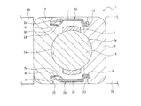
図1は、本発明に係る転がり軸受の第1の実施形態である深溝玉軸受の構造を示す部分縦断面図である。この深溝玉軸受1は、軌道面2aを外周面に有する円環状の内輪2と、内輪2の軌道面2aに対向する軌道面3aを内周面に有する円環状の外輪3と、両軌道面2a,3a間に転動自在に配された複数の転動体4と、を備えている。
Embodiments of a rolling bearing according to the present invention will be described in detail with reference to the drawings.
(First embodiment)
FIG. 1 is a partial longitudinal sectional view showing the structure of a deep groove ball bearing which is a first embodiment of a rolling bearing according to the present invention. The deep
外輪3において、深溝玉軸受1の回転軸方向の軌道面3aの内側面及び外側面には、シール溝3b,3cが深溝玉軸受1の回転軸と同軸の円環状にそれぞれ形成されている。シール溝3bには、後述するシール部材10の一方の端部13が取り付けられる。シール溝3cには、シール部材20の一方の端部13が取り付けられる。
また、内輪2において、深溝玉軸受1の回転軸方向の軌道面2aの内側面及び外側面には、シール溝2b,2cが深溝玉軸受1の回転軸と同軸の円環状にそれぞれ形成されている。シール溝2bは、後述するシール部材10の他方の端部12が当接する摺動面2dを有する。シール溝2cは、シール部材20の他方の端部22が当接する摺動面2eを有する。摺動面2d,2eとしては、シール溝2b,2cの内側壁面が好ましい。また、内輪2及び外輪3の間には、各転動体4を保持する保持器5が設けられている。
In the
Further, in the
そして、内輪2の内周面には軸部材60が嵌入されるとともに、回転ドラムの軸受支持部70に外輪3の外周面が嵌め込まれている。これにより、前記回転ドラムが深溝玉軸受1により回転可能に支持されている。
摺動面2d,2eには、耐食性被膜30が形成されている。この耐食性被膜30は、防錆性を有する固体潤滑剤を摺動面2d,2eに対してショットブラストすることにより形成される。
The
A corrosion-
この耐食性被膜30を構成する固体潤滑剤の種類は、防錆性を有していれば特に限定されるものではないが、例えば亜鉛及び錫を含むことが好ましい。亜鉛及び錫を含む耐食性被膜30は、亜鉛粒子をショットブラストした後に錫粒子をショットブラストすることにより形成することが好ましい。ただし、錫粒子をショットブラストした後に亜鉛粒子をショットブラストすることにより形成してもよいし、亜鉛粒子と錫粒子との混合物をショットブラストすることにより形成してもよい。
Although the kind of solid lubricant which comprises this corrosion-
この耐食性被膜30の厚さとしては、0.1μm以上5μm以下であることが好ましい。厚さが0.1以上であれば、例えば、外輪3に対して内輪2が回転することによる耐食性被膜30の脱落が生じにくく、シーリング効果を維持しつつ、摺動面2d,2eの摩擦抵抗を軽減し、転がり軸受1のトルクの上昇を抑えることができる。一方、耐食性被膜30の厚さが0.1μm未満であると、摺動面2d,2eにおける十分且つ持続的な耐食性が得られないおそれがある。また、耐食性被膜30の厚さが5μm超であると、その厚さによって耐食性被膜30に当接するシール部材10,20の弾性力が低下し、十分なシール機能を維持することが困難となるおそれがある。そして、耐食性被膜30には、バニシ仕上げが施されることが更に好ましい。
The thickness of the corrosion
シール部材10は、円環状の芯材11にゴムや合成樹脂などの弾性材を被覆させてなり、芯材11のラジアル方向に延びて形成されている。シール部材10の一方の端部13は、外輪3に形成されたシール溝3bに取り付けられている。シール部材10の他方の端部12は、芯材11の弾性力によって、内輪2に形成されたシール溝2bを構成する摺動面2dに当接している。
The sealing
シール部材20もシール部材10と同様に、円環状の芯材21にゴムや合成樹脂などの弾性材を被覆させてなり、芯材21のラジアル方向に延びて形成されている。シール部材20の一方の端部23は、外輪3に形成されたシール溝3cに取り付けられている。シール部材20の他方の端部22は、芯材11の弾性力によって、内輪2に形成されたシール溝2cを構成する摺動面2eに当接している。
Similarly to the
シール部材10,20に用いられる弾性材の材料としては、導電性のゴムが好ましい。シール部材10,20の被覆材の材料として導電性のゴムを採用することにより、シール部材10,20と、内輪2及び外輪3とが複数の箇所で接触しているため、導通確保の信頼性を高いものとすることができる。
耐食性被膜30を形成するために、摺動面2d,2eに固体潤滑剤をショットピーニングする処理方法については、特開2002−139052号公報に記載がある。この処理方法は、固体潤滑剤をショットピーニングすることで、物理的衝突エネルギー(衝突熱)により母村表面(摺動面2d,2e)に耐食性被膜30を溶着する方法である。
As a material of the elastic material used for the
Japanese Patent Application Laid-Open No. 2002-139052 discloses a processing method in which a solid lubricant is shot-peened on the sliding
本実施形態の転がり軸受における防錆性能の評価は、重量変化により評価することができる。耐食性の評価方法としては、錆が発生した面積を目視で測定してもよいが、特開平8−327342号公報に記載された評価方法を用いることが好ましい。この評価方法は、金属の錆発生面では、正常面より鏡面反射光が少なく、乱反射光が多いことを利用して、両反射強度の比によって錆発生面を認識し、自動的に錆発生面積を求める方法である。なお、この評価方法では、測定の迅速化及び省力化を達成したとされているが、本発明では、錆発生度合いを面積ではなく、「錆発生量=被評価金属の重量増加量」と定義することにより、従来技術より具体的な数値で錆を定量化することを可能にした。また、評価する金属は定められた試験片である必要がなく、形状を問わず錆を評価することが可能である。さらに、重量測定のみで判断可能なので、特別な装置や準備が不要である。 Evaluation of the rust prevention performance in the rolling bearing of this embodiment can be evaluated by a change in weight. As an evaluation method for corrosion resistance, the area where rust is generated may be measured visually, but the evaluation method described in JP-A-8-327342 is preferably used. This evaluation method uses the fact that the metal rust generation surface has less specular reflection light and more irregular reflection light than the normal surface, recognizes the rust generation surface by the ratio of both reflection intensities, and automatically rust generation area It is a method to ask for. In this evaluation method, it is said that speeding up of measurement and labor saving are achieved. However, in the present invention, the degree of rust generation is not an area but defined as “rust generation amount = weight increase amount of metal to be evaluated”. By doing so, it became possible to quantify rust with more specific values than in the prior art. Further, the metal to be evaluated does not need to be a predetermined test piece, and rust can be evaluated regardless of the shape. Furthermore, since it can be determined only by weight measurement, no special device or preparation is required.
耐食性被膜30は、摺動面2d,2e以外、例えば、内輪2の内側面、及び外輪3の外側面、保持器5、シール部材10,20、又はその他の付属の部材に形成されてもよい。耐食性被膜30を形成する方法については、摺動面2d,2e上に耐食性被膜30を形成する前述の方法と同様である。特に、これら保持器5、又はその他の付属の部材が鋼製である場合は、前述と同様の防錆効果が期待できる。保持器5の表面に耐食性被膜を形成することにより、少なくとも転動体との摺動部分において潤滑と防錆の効果が期待できる。また、その他の付属の部材の表面に耐食性被膜を形成することにより、外部環境との接点があるため、水分と接触する状況下などでは防錆効果が期待できる。間座やセパレータも同様である。さらに、通常の転がり軸受では、軸受外面の防錆のために防錆油を塗布することがあるが、軸受外面に塗布された防錆油が高温に晒されると、上記と同様に不快臭を発したり、気化蒸発して軸受の周辺環境に悪影響を与えることも考えられる。特に、軸受の近傍に樹脂製部品がある場合はその可能性が大きくなる。本発明に係る転がり軸受であれば、軸受外面の防錆油の塗布を省くことも可能であるため、上記のような問題が生じにくい。
The corrosion-
また、本実施形態では、シール部材10,20の表面、及びシール部材10,20の周辺に位置する各部材の表面に、撥水性の被膜が形成されてもよい。また、耐食性被膜30上に撥水性の被膜が形成されてもよい。この撥水性の被膜の形成については、特開2002−339995号公報の段落〔0025〕〜〔0029〕に開示された技術を用いることが好ましい。
In the present embodiment, a water-repellent film may be formed on the surfaces of the
また、近年では、インバータタイプの洗濯機が増加傾向であるため、インバータモータから発生する誘導電流によって引き起こされる電食の発生を軽減することを目的として、転動体4の材料をセラミックとしてもよい。
さらに、内輪2の内壁面や、外輪3の外壁面等の表面に、樹脂被膜や、セラミック容射層を形成してもよい。樹脂被膜の形成は、絶縁のみならず、転がり軸受1が発する振動をハウジングに伝達しにくくし、低振動化や、低騒音化に効果がある。
In recent years, since the number of inverter type washing machines has been increasing, the material of the rolling element 4 may be ceramic for the purpose of reducing the occurrence of electrolytic corrosion caused by the induced current generated from the inverter motor.
Furthermore, a resin coating or a ceramic spray layer may be formed on the inner wall surface of the
(第2の実施形態)
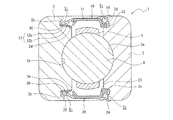
図2は、本発明に係る転がり軸受の第2の実施形態である深溝玉軸受の構造を示す部分縦断面図である。なお、本実施形態の説明においては、前述した第1の実施形態と重複する構成についての説明を省略する。
(Second Embodiment)
FIG. 2 is a partial longitudinal sectional view showing the structure of a deep groove ball bearing which is a second embodiment of the rolling bearing according to the present invention. In the description of the present embodiment, the description of the same configuration as that of the first embodiment described above is omitted.
図2に示すように、本実施形態の転がり軸受1は、シール部材10の他方の端部12に、複数のリップ部12a,12bが形成されている。外側のリップ部12bは、上面の数箇所に溝が形成されている。そして、シール溝2bと、複数のリップ部12a,12bとにより領域S1が形成される。以下、シール部材20についても同様の構成であるため、その説明を省略する。
As shown in FIG. 2, in the rolling
また、シール部材10には、一方の端部13とは別に分岐し、外輪3の側面部の一部を円環状に覆うように形成された鍔部14が形成される。そして、シール溝3bと、一方の端部13と、鍔部14とにより領域S2が形成される。鍔部14は、シール溝3bが形成されることによってできた外縁部3dを、一方の端部13と共に挟むように形成される。
転がり軸受の密封剤として用いられる従来のシール部材は、転がり軸受の運転(回転)時において、転がり軸受の内部の温度が上昇し、外部との間に圧力差が生じることを軽減するために、シール部材を貫通する貫通孔を設けることがあった。しかし、この貫通孔は、転がり軸受の内部に水分や埃等を侵入させるおそれがある。また、洗濯機の支持用主軸に用いられる従来の転がり軸受は、非接触の金属シールド板を装着したSUJ2鋼等よりなる軸受が使用され、この軸受と洗濯槽との間にオイルシール等を装着して、軸受部分に水分がかからないように設計されている。そのため、本実施形態の転がり軸受1では、シール部材10の他方の端部12に形成された複数のリップ部12a,12bのうち、外側(シール部材10における固定輪(内輪3)側)のリップ部12bの上面の数箇所に形成された溝が、他方の端部12が摺動面に当接した際に、この溝を通じて内圧を下げる効果を奏する。さらに、内側(シール部材10における回転輪(内輪2)側)のリップ部12aは、摺動面2d上に形成された耐食性被膜30に当接し、転がり軸受1の内部に水分が浸入することを防ぐ効果を奏する。
Further, the
A conventional seal member used as a sealant for a rolling bearing is used to reduce the occurrence of a pressure difference with the outside due to an increase in temperature inside the rolling bearing during operation (rotation) of the rolling bearing. A through hole penetrating the seal member may be provided. However, this through hole may cause moisture or dust to enter the inside of the rolling bearing. Also, the conventional rolling bearing used for the washing machine support spindle is made of SUJ2 steel with a non-contact metal shield plate, and an oil seal is installed between this bearing and the washing tub. Thus, it is designed so that moisture is not applied to the bearing portion. Therefore, in the rolling
また、摺動面2dに当接する他方の端部12が、複数のリップ部12a,12bを有することにより、軸受と洗濯槽との間にオイルシールを装着する必要がなくなり、装置の部品点数を減少させ、コストダウンを実現する効果を奏する。また、本実施形態の転がり軸受を用いることで、洗濯機の主軸を回転させるために必要なトルクも低減可能となるため、製品としての省エネルギーを促進する効果を奏する。
In addition, since the
また、本実施形態の転がり軸受1は、洗濯機の主軸として、内輪2が回転輪として使用され、外輪3が固定輪として使用された場合に、鍔部14,24の形成によってシール溝3b,3cに水が浸入しにくくなり、更なる防水性を発揮する。
なお、シール部材10には、複数のリップ部12a,12b、及び鍔部14の少なくともいずれか一方が形成されればよい。
Further, the rolling
The
リップ部12a,12bによって形成される円環状の溝部12cと耐食性被膜30とによって形成される領域S1、及びシール部材10の一方の端部13と鍔部14とシール溝3bとによって形成される領域S2の少なくともいずれか一方には、高粘度の流体が封入されることが好ましい(図2参照)。
領域S1及び領域S2の少なくともいずれか一方に封入される高粘度の流体は、高粘度のグリースであることが好ましく、さらに、導電性の高いグリース、導電性の高い油、イオン性液体等であることがより好ましく、耐水性、耐熱性、及び低トルク性の少なくともいずれかを備えたグリースであれば特に好ましい。具体的には、ジウレアを増長剤とし、ポリ―α―オレフィンを基油とし、カーボンブラックを添加したグリースが挙げられる。グリースの混和ちょう度としては、200〜300が好ましい。また、基油の粘度としては、30〜500mm2/s(40℃)が好ましい。
The region S 1 formed by the annular groove 12c formed by the
The high-viscosity fluid enclosed in at least one of the region S 1 and the region S 2 is preferably a high-viscosity grease. Furthermore, highly conductive grease, highly conductive oil, ionic liquid, etc. It is more preferable that the grease has at least one of water resistance, heat resistance and low torque. Specific examples include greases containing diurea as a thickener, poly-α-olefin as a base oil, and carbon black added. The blending degree of grease is preferably 200 to 300. Moreover, as a viscosity of a base oil, 30-500 mm < 2 > / s (40 degreeC) is preferable.
領域S1及び領域S2の少なくともいずれか一方に封入される流体の量としては、領域S1,S2の各容積の10〜70体積%とすることが好ましい。
領域S1及び領域S2の少なくともいずれか一方に封入される流体の量が、領域S1,S2の各容積の70体積%超過であると、トルクが大きくなるおそれがあるとともに、流体の漏洩が多くなるおそれがある。一方、10体積%未満であると、大気環境下での使用においては潤滑性が低くなり転がり軸受の耐久性が不十分となるおそれがある。真空環境下又は油脂類を嫌う環境下では、流体の封入量は少ない方が好ましい。
The amount of fluid sealed in at least one of the region S 1 and the region S 2 is preferably 10 to 70% by volume of each volume of the regions S 1 and S 2 .
If the amount of fluid sealed in at least one of the region S 1 and the region S 2 exceeds 70% by volume of each volume of the regions S 1 and S 2 , the torque may increase, There is a risk of increased leakage. On the other hand, if it is less than 10% by volume, the lubricity becomes low when used in an atmospheric environment, and the durability of the rolling bearing may be insufficient. In a vacuum environment or an environment where oils and fats are disliked, it is preferable that the amount of fluid enclosed is small.
このような流体を用いることにより、内輪2と外輪3との間の導電性確保のみならず、転がり軸受1の内部への水分の侵入の防止効果の向上、並びに、外輪3に対して内輪2を回転させたときのトルクの減少等の効果が得られる。
By using such a fluid, not only the conductivity between the
(第3の実施形態)
上記実施形態においては、転がり軸受の例として深溝玉軸受を挙げて説明したが、転がり軸受の種類は深溝玉軸受に限定されるものではなく、本発明は様々な種類の転がり軸受に対して適用することができる。例えば、アンギュラ玉軸受,自動調心玉軸受,自動調心ころ軸受,針状ころ軸受,円筒ころ軸受,円すいころ軸受等のラジアル形の転がり軸受や、スラスト玉軸受,スラストころ軸受等のスラスト形の転がり軸受である。これらの中でも、アンギュラ玉軸受に適用することが好ましい。
(Third embodiment)
In the above embodiment, a deep groove ball bearing has been described as an example of a rolling bearing. However, the type of the rolling bearing is not limited to the deep groove ball bearing, and the present invention is applied to various types of rolling bearings. can do. For example, radial type rolling bearings such as angular contact ball bearings, self-aligning ball bearings, self-aligning roller bearings, needle roller bearings, cylindrical roller bearings, tapered roller bearings, and thrust types such as thrust ball bearings and thrust roller bearings This is a rolling bearing. Among these, it is preferable to apply to an angular ball bearing.
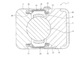
図3は、本発明に係る転がり軸受の第3の実施形態における構成を示す部分縦断面図である。なお、本実施形態の説明においても、前述した第1の実施形態と重複する構成についての説明を省略する。図3に示すように、本実施形態における転がり軸受は、転動体4の球面部と、内輪及び外輪のそれぞれの接触面との接触方向が、回転中心軸と直交する直交面に対して所定の接触角を有するアンギュラタイプの軸受である。 FIG. 3 is a partial vertical cross-sectional view showing the configuration of the rolling bearing according to the third embodiment of the present invention. In the description of the present embodiment, the description of the same configuration as that of the first embodiment is omitted. As shown in FIG. 3, the rolling bearing in the present embodiment has a predetermined contact direction between the spherical surface portion of the rolling element 4 and the contact surfaces of the inner ring and the outer ring with respect to an orthogonal plane orthogonal to the rotation center axis. It is an angular type bearing having a contact angle.
本実施形態のように、転がり軸受の構造をアンギュラタイプとすることで、転がり軸受の内外径の幅寸法が同一であっても、転動体の数を増やすことが可能であり、転がり軸受の付加容量を増やせるので、大容量のドラムに適している。
また、転動体をセラミックとした場合、転がり軸受の構造をアンギュラとすれば、転動体1個あたりの負荷を減少できるため、転がり軸受の駆動の信頼性が向上する効果がある。特に、アルミナ−ジルコニア等の、いわゆる低コストセラミックの転動体の場合、転動体が増えてもコスト増は僅かなため、アンギュラ方式は有効な手段である。
Like this embodiment, by making the structure of the rolling bearing an angular type, it is possible to increase the number of rolling elements even if the width dimension of the inner and outer diameters of the rolling bearing is the same. Since the capacity can be increased, it is suitable for large-capacity drums.
Further, when the rolling element is made of ceramic, if the structure of the rolling bearing is angular, the load per rolling element can be reduced, so that the driving reliability of the rolling bearing is improved. In particular, in the case of so-called low-cost ceramic rolling elements such as alumina-zirconia, even if the number of rolling elements increases, the cost increase is slight, so the angular system is an effective means.
(第4の実施形態)
図4は、本発明に係る転がり軸受の第4の実施形態における構成を示す部分縦断面図である。なお、本実施形態の説明においても、前述した第1の実施形態と重複する構成についての説明を省略する。図4に示すように、転がり軸受1の外輪3の外周面に溝部3eを形成し、この溝部3eにOリング40を取り付けてもよい。また、図示はしないが、内輪3の内周面に形成した溝部にOリングを取り付けてもよい。転がり軸受1の外輪3の外周面及び内輪2の内周面の少なくともいずれか一方にOリングを取り付けることによって、クリープの防止のみならず、転がり軸受1と、回転ドラムの軸部材60や軸受支持部70との間に隙間がある場合に、その隙間から外部へ出ようとする水分を止めることができる。なお、Oリング40が取り付けられる溝部3eに上記耐食性被膜30を施してもよい。
(Fourth embodiment)
FIG. 4 is a partial longitudinal sectional view showing the configuration of the rolling bearing according to the fourth embodiment of the present invention. In the description of the present embodiment, the description of the same configuration as that of the first embodiment is omitted. As shown in FIG. 4, the
(第5の実施形態)
図5は、本発明に係る転がり軸受の第5の実施形態における構成を示す部分縦断面図である。なお、本実施形態の説明においても、前述した第1の実施形態と重複する構成についての説明を省略する。図4に示すように、静止輪である外輪3の外側壁面上に肉厚部50を形成して、外輪3の側面において当接する領域が拡大されるように鍔部15を形成してもよい。また、外輪3の側面において、鍔部25が埋設される溝部3fを形成し、外輪3の側面と鍔部25の表面とが略面一になるように設置してもよい。
(Fifth embodiment)
FIG. 5 is a partial longitudinal sectional view showing the configuration of the rolling bearing according to the fifth embodiment of the present invention. In the description of the present embodiment, the description of the same configuration as that of the first embodiment is omitted. As shown in FIG. 4, the
1 転がり軸受
2 内輪
2a 軌道面
2b シール溝
2c シール溝
2d 摺動面
3 外輪
3a 軌道面
3b シール溝
3c シール溝
4 転動体
10 シール部材
12 他方の端部
12a 第1のリップ部
12b 第2のリップ部
13 一方の端部
14 鍔部
30 耐食性被膜
DESCRIPTION OF
Claims (7)
Priority Applications (1)
| Application Number | Priority Date | Filing Date | Title |
|---|---|---|---|
| JP2009033912A JP2010190282A (en) | 2009-02-17 | 2009-02-17 | Roll bearing |
Applications Claiming Priority (1)
| Application Number | Priority Date | Filing Date | Title |
|---|---|---|---|
| JP2009033912A JP2010190282A (en) | 2009-02-17 | 2009-02-17 | Roll bearing |
Related Child Applications (1)
| Application Number | Title | Priority Date | Filing Date |
|---|---|---|---|
| JP2012226277A Division JP5637198B2 (en) | 2012-10-11 | 2012-10-11 | Rolling bearing for motor |
Publications (2)
| Publication Number | Publication Date |
|---|---|
| JP2010190282A true JP2010190282A (en) | 2010-09-02 |
| JP2010190282A5 JP2010190282A5 (en) | 2012-01-19 |
Family
ID=42816543
Family Applications (1)
| Application Number | Title | Priority Date | Filing Date |
|---|---|---|---|
| JP2009033912A Pending JP2010190282A (en) | 2009-02-17 | 2009-02-17 | Roll bearing |
Country Status (1)
| Country | Link |
|---|---|
| JP (1) | JP2010190282A (en) |
Cited By (4)
| Publication number | Priority date | Publication date | Assignee | Title |
|---|---|---|---|---|
| JP2017155826A (en) * | 2016-03-01 | 2017-09-07 | Ntn株式会社 | Tapered roller bearing |
| JP2020153522A (en) * | 2020-06-24 | 2020-09-24 | Ntn株式会社 | Conical roller bearing |
| US11274704B2 (en) * | 2018-01-15 | 2022-03-15 | Audi Ag | Sealing arrangement for a wheel bearing arrangement of a motor vehicle |
| CN114791016A (en) * | 2022-03-02 | 2022-07-26 | 湖南华园莱客科技有限公司 | Air bearing that multiple ring cup jointed |
Citations (2)
| Publication number | Priority date | Publication date | Assignee | Title |
|---|---|---|---|---|
| JP2000018264A (en) * | 1998-07-06 | 2000-01-18 | Nippon Seiko Kk | Rolling bearing with seal |
| JP2008180374A (en) * | 2006-12-28 | 2008-08-07 | Nsk Ltd | Rolling bearing |
-
2009
- 2009-02-17 JP JP2009033912A patent/JP2010190282A/en active Pending
Patent Citations (2)
| Publication number | Priority date | Publication date | Assignee | Title |
|---|---|---|---|---|
| JP2000018264A (en) * | 1998-07-06 | 2000-01-18 | Nippon Seiko Kk | Rolling bearing with seal |
| JP2008180374A (en) * | 2006-12-28 | 2008-08-07 | Nsk Ltd | Rolling bearing |
Cited By (5)
| Publication number | Priority date | Publication date | Assignee | Title |
|---|---|---|---|---|
| JP2017155826A (en) * | 2016-03-01 | 2017-09-07 | Ntn株式会社 | Tapered roller bearing |
| US11274704B2 (en) * | 2018-01-15 | 2022-03-15 | Audi Ag | Sealing arrangement for a wheel bearing arrangement of a motor vehicle |
| JP2020153522A (en) * | 2020-06-24 | 2020-09-24 | Ntn株式会社 | Conical roller bearing |
| CN114791016A (en) * | 2022-03-02 | 2022-07-26 | 湖南华园莱客科技有限公司 | Air bearing that multiple ring cup jointed |
| CN114791016B (en) * | 2022-03-02 | 2024-03-19 | 湖南华园莱客科技有限公司 | Air bearing that polycyclic cup jointed |
Similar Documents
| Publication | Publication Date | Title |
|---|---|---|
| US8801292B2 (en) | Roller bearing | |
| CN202926888U (en) | Double column angular contact ball bearing | |
| JP2010190282A (en) | Roll bearing | |
| JP2010025155A (en) | Conical roller bearing for wheel | |
| JP5637198B2 (en) | Rolling bearing for motor | |
| US7926817B2 (en) | Sealing apparatus and bearing apparatus having the same | |
| JP2013092175A (en) | Roller bearing and method of manufacturing the same | |
| RU2319869C2 (en) | Method to increase service life of antifriction bearing | |
| JP2011208662A (en) | Rolling bearing | |
| US7786637B2 (en) | Touchdown bearing | |
| JP2008180374A (en) | Rolling bearing | |
| US9638253B2 (en) | Bearing | |
| JP2010071374A (en) | Rolling device | |
| JP4513775B2 (en) | Rolling device for rolling mill roll neck | |
| JP2017166548A (en) | Wheel bearing device | |
| JP2007002912A (en) | Rolling bearing | |
| CA2728945A1 (en) | Roller bearing for underwater applications | |
| JP2006266405A (en) | Rolling bearing and its manufacturing method | |
| JP5926061B2 (en) | Sealed rolling bearing | |
| JP2009204078A (en) | Rolling device | |
| JP2014234901A (en) | Rolling bearing | |
| JP2007100870A (en) | Rolling device | |
| WO2024053666A1 (en) | Bearing sealing device and vehicular bearing device | |
| JP2008002532A (en) | Bearing for steel facilities | |
| US20240125351A1 (en) | Thrust needle roller bearing |
Legal Events
| Date | Code | Title | Description |
|---|---|---|---|
| A521 | Written amendment |
Free format text: JAPANESE INTERMEDIATE CODE: A523 Effective date: 20111128 |
|
| A621 | Written request for application examination |
Free format text: JAPANESE INTERMEDIATE CODE: A621 Effective date: 20111128 |
|
| A977 | Report on retrieval |
Free format text: JAPANESE INTERMEDIATE CODE: A971007 Effective date: 20120808 |
|
| A131 | Notification of reasons for refusal |
Free format text: JAPANESE INTERMEDIATE CODE: A131 Effective date: 20120821 |
|
| A02 | Decision of refusal |
Free format text: JAPANESE INTERMEDIATE CODE: A02 Effective date: 20130108 |