JP2010183396A - Image processing apparatus, image forming device, imaging processing method, and program - Google Patents
Image processing apparatus, image forming device, imaging processing method, and program Download PDFInfo
- Publication number
- JP2010183396A JP2010183396A JP2009025630A JP2009025630A JP2010183396A JP 2010183396 A JP2010183396 A JP 2010183396A JP 2009025630 A JP2009025630 A JP 2009025630A JP 2009025630 A JP2009025630 A JP 2009025630A JP 2010183396 A JP2010183396 A JP 2010183396A
- Authority
- JP
- Japan
- Prior art keywords
- image
- saturation
- color
- color unevenness
- chip
- Prior art date
- Legal status (The legal status is an assumption and is not a legal conclusion. Google has not performed a legal analysis and makes no representation as to the accuracy of the status listed.)
- Granted
Links
- 238000012545 processing Methods 0.000 title claims description 123
- 238000003672 processing method Methods 0.000 title claims description 9
- 238000003384 imaging method Methods 0.000 title abstract description 8
- 238000006243 chemical reaction Methods 0.000 claims abstract description 58
- 230000001629 suppression Effects 0.000 claims abstract description 39
- 238000000034 method Methods 0.000 claims description 64
- 238000004364 calculation method Methods 0.000 claims description 19
- 238000012937 correction Methods 0.000 description 54
- 239000011521 glass Substances 0.000 description 19
- 230000006870 function Effects 0.000 description 16
- 238000000926 separation method Methods 0.000 description 15
- 230000003287 optical effect Effects 0.000 description 13
- 238000010586 diagram Methods 0.000 description 11
- 239000003086 colorant Substances 0.000 description 7
- 230000006835 compression Effects 0.000 description 7
- 238000007906 compression Methods 0.000 description 7
- 238000005286 illumination Methods 0.000 description 4
- 230000002159 abnormal effect Effects 0.000 description 3
- 230000006837 decompression Effects 0.000 description 3
- 239000000428 dust Substances 0.000 description 3
- 230000000694 effects Effects 0.000 description 3
- 238000012546 transfer Methods 0.000 description 3
- 230000000007 visual effect Effects 0.000 description 3
- 230000015572 biosynthetic process Effects 0.000 description 2
- 238000004040 coloring Methods 0.000 description 2
- 230000007423 decrease Effects 0.000 description 2
- 230000006866 deterioration Effects 0.000 description 2
- 230000010365 information processing Effects 0.000 description 2
- 230000002093 peripheral effect Effects 0.000 description 2
- 238000013139 quantization Methods 0.000 description 2
- 239000004065 semiconductor Substances 0.000 description 2
- 239000000758 substrate Substances 0.000 description 2
- 229910052724 xenon Inorganic materials 0.000 description 2
- FHNFHKCVQCLJFQ-UHFFFAOYSA-N xenon atom Chemical compound [Xe] FHNFHKCVQCLJFQ-UHFFFAOYSA-N 0.000 description 2
- 241000282412 Homo Species 0.000 description 1
- 230000005856 abnormality Effects 0.000 description 1
- 238000009792 diffusion process Methods 0.000 description 1
- 238000000605 extraction Methods 0.000 description 1
- 238000009499 grossing Methods 0.000 description 1
- 238000003702 image correction Methods 0.000 description 1
- 230000001678 irradiating effect Effects 0.000 description 1
- 239000002184 metal Substances 0.000 description 1
- 229910052751 metal Inorganic materials 0.000 description 1
- 238000012634 optical imaging Methods 0.000 description 1
- 229920006267 polyester film Polymers 0.000 description 1
- 229920006395 saturated elastomer Polymers 0.000 description 1
- 238000012360 testing method Methods 0.000 description 1
- 238000011144 upstream manufacturing Methods 0.000 description 1
- 210000000707 wrist Anatomy 0.000 description 1
Images


Abstract
Description
この発明は、ファクシミリ装置、プリンタ、スキャナ、複写機、複合機、パーソナルコンピュータを含む装置に適用される画像処理装置と、ファクシミリ装置、プリンタ、スキャナ、複写機、複合機を含む画像形成装置と、上記画像処理装置と上記画像形成装置で実施される画像処理方法と、上記画像処理装置と上記画像形成装置で実行させるプログラムに関する。 The present invention relates to an image processing apparatus applied to an apparatus including a facsimile machine, a printer, a scanner, a copying machine, a multifunction machine, and a personal computer, and an image forming apparatus including a facsimile machine, a printer, a scanner, a copying machine, a multifunction machine, The present invention relates to an image processing method executed by the image processing apparatus and the image forming apparatus, and a program executed by the image processing apparatus and the image forming apparatus.
従来、画像読取装置における原稿の読み取り方式としては、例えばキセノンランプを光源とする光を原稿に照射させ、原稿からの反射光を縮小光学系を介してイメージセンサで読み取る方式が一般的であった。
しかし、最近では、装置の小型化を目的として、形状の小さい発光ダイオード(Light Emitting Diode:LED)を光源に利用し、例えばセルフォックレンズを介してリニアセンサで画像を直接読み取るコンタクトイメージセンサ(Contact Image Sensor:CIS)と呼ばれるものが広く普及し始めている。
このようなCISにおけるイメージセンサとしては、光電変換センサを直線状に並べたセンサチップを、主走査方向に複数並べて構成した所謂マルチチップ方式のイメージセンサアレイが広く用いられている。
ただし、マルチチップ方式のイメージセンサアレイでは、各々のチップごとに特性が異なるため、原稿を読み取った時にチップの幅で色むらが発生してしまうという問題があった。すなわち、極端な場合には、読み取った画像データに縞模様が出来てしまう。
Conventionally, as a method for reading a document in an image reading apparatus, for example, a method of irradiating a document with light using a xenon lamp as a light source and reading reflected light from the document with an image sensor through a reduction optical system has been common. .
However, recently, for the purpose of reducing the size of the apparatus, a light emitting diode (LED) having a small shape is used as a light source, and for example, a contact image sensor (Contact) that directly reads an image with a linear sensor via a Selfoc lens. What is called Image Sensor (CIS) has begun to spread widely.
As such an image sensor in the CIS, a so-called multi-chip type image sensor array in which a plurality of sensor chips in which photoelectric conversion sensors are arranged in a straight line is arranged in the main scanning direction is widely used.
However, the multi-chip type image sensor array has a problem that color unevenness occurs due to the width of the chip when the document is read because the characteristics are different for each chip. That is, in an extreme case, a striped pattern is formed on the read image data.
従来、特許文献1にあるように、テストチャートをイメージセンサアレイで読み取り、チップごとに色補正係数を算出した上で、各チップを一つの色空間をターゲットとして変換する技術が提案されている。
また、近年では自動原稿送り装置(Auto Document Feeder:ADF)を用いて、1枚の原稿の両面を同時に読み取る装置(時間の完全一致ではなく、同一の原稿搬送時程度の意味)が普及し始めている。
例えば、特許文献2に記載の読取装置では、両面同時読取時は、光学系を固定した状態で原稿を搬送しながら読み取りを行う際、原稿の片方の面については、マルチチップイメージセンサを含むCISと呼ばれる読取装置を使用して読み取りを行い、もう一方の面については、CCDをイメージセンサとする縮小光学系を用いて読み取りを行うことになる。
Conventionally, as disclosed in Patent Document 1, a technique has been proposed in which a test chart is read by an image sensor array, a color correction coefficient is calculated for each chip, and each chip is converted using one color space as a target.
Further, in recent years, an apparatus that simultaneously reads both sides of a single document using an automatic document feeder (ADF) (meaning the time of conveying the same document, not exactly the same time) has begun to spread. Yes.
For example, in the reading apparatus described in Patent Document 2, when performing both-side simultaneous reading while reading an original while the optical system is fixed, one side of the original is CIS including a multi-chip image sensor. The other side is read using a reduction optical system using a CCD as an image sensor.
しかしながら、上述した特許文献1の技術では、チップ間の色補正の性能としては完全ではなく、色むらが残ってしまうという問題があった。
キャリブレーション技術などでチップ間の色補正精度を向上させても、ターゲットに完全に一致させることは困難であり、誤差が生じてしまう。
特に、低彩度領域において出力色が変動し、ターゲットとする彩度よりも高い彩度で再現されてしまった場合は、一般に人間は色むらとして認識しやすい。
人間の視覚特性は、有彩色に比べて無彩色の方が色の変化を見分けやすいので、特に無彩領域における変動により敏感である。
また、上述した特許文献2の技術では、マルチチップイメージセンサに起因するより色むらを抑制するため、CCDイメージセンサに対して同一の処理をかけると、不必要に低彩度部の彩度が下がってしまうため、一般的にはCCDセンサ読み取り時は色むら抑制のための彩度調整処理は行わない方が良いと考えられる。
However, the technique disclosed in Patent Document 1 described above has a problem that color correction performance between chips is not perfect, and color unevenness remains.
Even if the color correction accuracy between chips is improved by a calibration technique or the like, it is difficult to completely match the target, and an error occurs.
In particular, when the output color fluctuates in a low saturation region and is reproduced with a saturation higher than the target saturation, it is generally easy for humans to recognize color unevenness.
Human visual characteristics are particularly sensitive to fluctuations in the achromatic region, since achromatic colors are more easily discerned than chromatic colors.
Further, in the technique of Patent Document 2 described above, if the same processing is applied to the CCD image sensor in order to suppress color unevenness caused by the multi-chip image sensor, the saturation of the low saturation portion is unnecessarily increased. Therefore, it is generally considered that it is better not to perform saturation adjustment processing for suppressing color unevenness when reading a CCD sensor.
しかし、自動原稿送り装置を用いた両面同時読み取りにおける表面と裏面、さらには原稿を固定して読み取るブック読み取り(コンタクトガラス上に原稿を固定し、読み取り光学系を走査することで読み取る方法)とで、低彩度部の彩度に差があり、画像の差異として認識されてしまうことも考えられる。
従って、ユーザによっては、あえてCCDイメージセンサで読み取る場合もマルチチップイメージセンサ読み取り同等の彩度調整処理をかける事を望まれることも考えられる。
この発明は上記の点に鑑みてなされたものであり、無彩部で色の変動がマルチチップイメージセンサのチップ単位で生じた場合においても、色むらが知覚されにくい色再現を用途に応じてユーザが望むようにできるようにすることを目的とする。
However, the front and back sides of a double-sided simultaneous reading using an automatic document feeder, and book reading (fixing the document on the contact glass and scanning the scanning optical system) It is also conceivable that there is a difference in the saturation of the low saturation part and it is recognized as an image difference.
Therefore, some users may want to apply saturation adjustment processing equivalent to multi-chip image sensor reading even when reading with a CCD image sensor.
The present invention has been made in view of the above points, and even when color variation occurs in an achromatic portion on a chip basis of a multi-chip image sensor, color reproduction in which color unevenness is not easily perceived according to the application. The purpose is to allow the user to do what he wants.
この発明は上記の目的を達成するため、入力光を電気信号に変換するイメージセンサを一方向に複数個並べたマルチチップイメージセンサを備えたフルカラー画像読取手段と、上記フルカラー画像読取手段によって読み取られた画像の画像信号に対して上記マルチチップイメージセンサを構成するチップ幅の単位で発生する色むらを抑制する色むら抑制手段と、上記画像信号に対して指定された出力用途に応じて上記色むら抑制手段による抑制を実施するか否かを切り換える手段を備えた画像処理装置を提供する。
また、上記色むら抑制手段は、上記フルカラー画像読取手段によって読み取られた画像の画像信号から彩度データを算出する彩度算出手段と、上記彩度算出手段で算出された彩度データを用いて彩度を調整する彩度調整手段を備え、上記彩度調整手段を用いて低彩度の画像信号に対してのみ彩度を落とす変換を行うことにより、マルチチップイメージセンサを構成するチップ幅の単位で発生する色むらを抑制する手段にするとよい。
さらに、上記出力用途を、カラーモードの種類にするとよい。
In order to achieve the above object, the present invention provides a full-color image reading means having a multi-chip image sensor in which a plurality of image sensors for converting input light into electric signals are arranged in one direction, and is read by the full-color image reading means. Color unevenness suppressing means for suppressing color unevenness generated in units of chip widths constituting the multichip image sensor with respect to the image signal of the obtained image, and the color according to the output application specified for the image signal Provided is an image processing apparatus provided with means for switching whether or not to perform suppression by unevenness suppression means.
Further, the color unevenness suppressing means uses saturation calculation means for calculating saturation data from the image signal of the image read by the full-color image reading means, and saturation data calculated by the saturation calculation means. Saturation adjustment means for adjusting the saturation is provided, and conversion is performed to reduce the saturation only for low-saturation image signals using the saturation adjustment means, thereby reducing the chip width of the multi-chip image sensor. It may be a means for suppressing color unevenness generated in units.
Furthermore, the output application may be a color mode type.
また、上記切り換える手段は、上記画像信号に対して指定されたカラーモードの種類がフルカラーモードである場合は上記色むら抑制手段による抑制を実施するように切り換え、モノクロモードである場合は上記色むら抑制手段による抑制を実施しないように切り換える手段にするとよい。
さらに、上記色むら抑制手段は、上記画像信号の色空間を上記画像信号の出力先の色空間と最適になるように色むらを抑制する手段にするとよい。
また、上記色むら抑制手段は、上記画像信号の出力先が印刷手段であるときは、上記画像信号の色空間を紙出力用の色空間と最適になるように色むらを抑制する手段にするとよい。
さらに、上記色むら抑制手段は、上記画像信号の出力先がネットワークを介して通信する端末装置の表示手段であるときは、上記画像信号の色空間をディスプレイ出力用のsRGBの色空間と最適になるように色むらを抑制する手段にするとよい。
The switching means switches so that the color unevenness suppressing means performs suppression when the color mode type designated for the image signal is the full color mode, and the color unevenness when the color mode is the monochrome mode. It is good to make it the means to switch so that suppression by a suppression means may not be implemented.
Further, the color unevenness suppressing means may be a means for suppressing color unevenness so that the color space of the image signal is optimized with the color space of the output destination of the image signal.
In addition, when the output destination of the image signal is a printing unit, the color unevenness suppressing unit is a unit that suppresses the color unevenness so that the color space of the image signal is optimized as the color space for paper output. Good.
Furthermore, when the output destination of the image signal is a display unit of a terminal device that communicates via a network, the color unevenness suppression unit optimizes the color space of the image signal as the sRGB color space for display output. It is preferable to use means for suppressing color unevenness.
また、上記のような画像処理装置と、上記画像信号に基づいて印刷する印刷手段を備えた画像形成装置を提供する。
さらに、入力光を電気信号に変換するイメージセンサを一方向に複数個並べたマルチチップイメージセンサを備えたフルカラー画像読取手段によって読み取られた画像の画像信号に対して上記マルチチップイメージセンサを構成するチップ幅の単位で発生する色むらを抑制する色むら抑制工程と、上記画像信号に対して指定された出力用途に応じて上記色むら抑制工程による抑制を実施するか否かを切り換える工程とからなり、上記色むら抑制工程は、上記フルカラー画像読取手段によって読み取られた画像の画像信号から彩度データを算出する彩度算出工程と、上記彩度算出工程で算出された彩度データを用いて彩度を調整する彩度調整工程を有し、上記彩度調整工程によって低彩度の画像信号に対してのみ彩度を落とす変換を行うことにより、マルチチップイメージセンサを構成するチップ幅の単位で発生する色むらを抑制する工程である画像処理方法も提供する。
The present invention also provides an image forming apparatus including the image processing apparatus as described above and a printing unit that performs printing based on the image signal.
Further, the multi-chip image sensor is configured for an image signal of an image read by a full-color image reading means provided with a multi-chip image sensor in which a plurality of image sensors for converting input light into electric signals are arranged in one direction. A color unevenness suppressing step for suppressing color unevenness generated in units of chip widths, and a step of switching whether or not the color unevenness suppressing step is performed according to the output application specified for the image signal. Thus, the color unevenness suppressing step uses a saturation calculation step for calculating saturation data from an image signal of an image read by the full-color image reading unit, and the saturation data calculated in the saturation calculation step. A saturation adjustment step for adjusting the saturation, and performing the conversion for reducing the saturation only for the low saturation image signal by the saturation adjustment step. Ri also provides an image processing method is a step of suppressing the color irregularity occurring in units of chip width constituting a multi-chip image sensor.
さらにまた、コンピュータに、入力光を電気信号に変換するイメージセンサを一方向に複数個並べたマルチチップイメージセンサを備えたフルカラー画像読取手段によって読み取られた画像の画像信号に対して上記マルチチップイメージセンサを構成するチップ幅の単位で発生する色むらを抑制する色むら抑制手順と、上記画像信号に対して指定された出力用途に応じて上記色むら抑制手順による抑制を実施するか否かを切り換える手順を実施させ、上記色むら抑制手順では、上記フルカラー画像読取手段によって読み取られた画像の画像信号から彩度データを算出する彩度算出手順と、上記彩度算出手順で算出された彩度データを用いて彩度を調整する彩度調整手順を実施させ、上記彩度調整手順によって低彩度の画像信号に対してのみ彩度を落とす変換を行うことにより、マルチチップイメージセンサを構成するチップ幅の単位で発生する色むらを抑制させるプログラムも提供する。 Furthermore, the multi-chip image is output for the image signal of the image read by the full-color image reading means provided with a multi-chip image sensor in which a plurality of image sensors for converting input light into an electrical signal are arranged in one direction on a computer. Whether to implement the color unevenness suppression procedure that suppresses the color unevenness that occurs in the unit of the chip width constituting the sensor and the color unevenness suppression procedure according to the output application specified for the image signal. In the color unevenness suppression procedure, a saturation calculation procedure for calculating saturation data from an image signal of an image read by the full-color image reading means, and a saturation calculated by the saturation calculation procedure. Saturation adjustment procedure for adjusting saturation using data is performed, and only the low saturation image signal is saturated by the above saturation adjustment procedure. By performing conversion dropping also provides a program to suppress the color unevenness which occurs in units of chip width constituting a multi-chip image sensor.
この発明による画像処理装置と画像形成装置と画像処理方法は、無彩部で色の変動がマルチチップイメージセンサのチップ単位で生じた場合においても、色むらが知覚されにくい色再現を用途に応じてユーザが望むようにすることができる。
また、この発明によるプログラムは、コンピュータに、無彩部で色の変動がマルチチップイメージセンサのチップ単位で生じた場合においても、色むらが知覚されにくい色再現を用途に応じてユーザが望むようにするための機能を実現させることができる。
According to the image processing apparatus, the image forming apparatus, and the image processing method according to the present invention, color reproduction that makes it difficult to perceive color unevenness even when a color variation occurs in a chip unit of a multi-chip image sensor in an achromatic portion according to the application. Can be as desired by the user.
In addition, the program according to the present invention allows a user to desire color reproduction that makes it difficult for color unevenness to be perceived even when color variation occurs in a chip unit of a multi-chip image sensor in an achromatic portion. It is possible to realize a function for
以下、この発明を実施するための形態を図面に基づいて具体的に説明する。
〔実施例〕
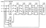
図1は、この発明の画像処理装置の実施例に係るデジタル式のフルカラー画像処理装置の概略構成を示したブロック図である。
このフルカラー画像処理装置は、フルカラー複写機として動作する場合、両面原稿読取部101、及び第2画像読取部102は原稿からレッド(R)、グリーン(G)、ブルー(B)に色分解した画像データを読み取り、当該画像データ(アナログ信号)をデジタルデータに変換して出力する。この各読取部で生成したそれぞれの画像データは、一時的に十分な大きさの容量を備えたメモリ103に蓄積される。
メモリ103に蓄積されたデータは、メモリ制御部106の制御に従い、後段のスキャナ補正部104に出力される。
Hereinafter, embodiments for carrying out the present invention will be specifically described with reference to the drawings.
〔Example〕
FIG. 1 is a block diagram showing a schematic configuration of a digital full-color image processing apparatus according to an embodiment of the image processing apparatus of the present invention.
When this full-color image processing apparatus operates as a full-color copying machine, the double-sided
The data stored in the
メモリ制御部106は、メモリ103への画像データの蓄積処理とメモリ103からの画像データの取り出しをコントロールする。
例えば、両面原稿読取部101により、原稿のある一つの面(仮に表面とする)の画像データを先に処理して、次に原稿の他方の面(仮に裏面とする)の画像データを処理するように、いったん両面画像を全てメモリ103に蓄積しておき、表面の画像データを送出し終わってから裏面の画像データをメモリ103から呼び出して送出する。
原稿を連続して読み取りを行う場合は、表面の画像データと裏面の画像データを、交互にスキャナ補正部104に送出することになる。
後述するように、表面と裏面とでは、読取特性の異なる二つのイメージセンサを用いて読み取りを行っているため、スキャナ補正部104は、通常は別々のパラメータを用いてスキャナ補正を行う必要がある。
The
For example, the double-sided
When the document is read continuously, the front side image data and the back side image data are alternately sent to the
As will be described later, since reading is performed using two image sensors having different reading characteristics on the front surface and the back surface, the
スキャナ補正部104は、後で述べるように、両面原稿読取部101又は第2画像読取部102で読み取ったRGB画像データ(デジタルデータ)について、スキャナγ補正処理をしたり、画像領域を文字・線画や絵柄などに分類(像域分離)したり、像域分離の判定結果に応じて画像の文字部は強調して絵柄部は平滑化するフィルタ処理をしたり、読み取った色を用途に応じた色空間に変換したりなどの画像処理を施して両面原稿読取部101又は第2画像読取部102の特性を補正する。
圧縮処理部105は、スキャナ補正部104によるスキャナ補正後の多値画像データを圧縮処理して、汎用バス113にデータを送出する。圧縮後の画像データは汎用バス113を通って、コントローラ110に送られる。
コントローラ110は、図示を省略したCPU,ROM,RAM(半導体メモリ)を備えたマイクロコンピュータであり、圧縮処理部105から送られたデータをRAMに蓄積するようになっている。
As will be described later, the
The
The
なお、上に記したように、スキャナ補正部104には、両面原稿読取部101と第2画像読取部102のそれぞれ特性の異なる二つの読取センサで読み取った画像が入力されてくる。そのタイミングについては、メモリ制御部106により表面、裏面の画像が交互に入力されることになるが、表面の画像が入力される直前のタイミングで、表面用のパラメータ設定がスキャナ補正部104になされ、処理が終わった後に裏面の画像が入力される直前のタイミングで、裏面用のパラメータ設定がスキャナ補正部104になされる。これにより、読取特性の違いをほぼ吸収するような画像処理を行い、表面と裏面で同等の画像を出力することができる。
また、例えば、このフルカラー画像処理装置を備えた複合機(MFP)における実際の制御では、MFP全体の制御を統括するCPU(ここでは図示省略)が存在し、メモリ制御部106やスキャナ補正部104と通信を行い、予め図示を省略したROMに記憶された表面用パラメータ、裏面用パラメータの切り替えを、画像の入出力に同期して行っている。
As described above, the
Further, for example, in actual control in a multifunction peripheral (MFP) equipped with this full-color image processing apparatus, there is a CPU (not shown here) that controls the entire MFP, and the
次に、コントローラ110に蓄積されたデータは随時大容量の記憶装置であるハードディスクドライブ(HDD)111に書き込まれる。このHDD111に画像データを書き込むのは、プロッタ107によるプリントアウト時に用紙が詰まり、出力が正常に終了しなかった場合でも再び原稿を読み直すのを避けるためや、複数の原稿画像データを並べ替える電子ソートを行うためや、読み取った原稿を蓄積しておき、必要なときに再出力するためである。
なお、この実施例では、画像データに対して圧縮を施す場合を示したが、汎用バス113の帯域が十分に広く、画像データを蓄積するHDD111の容量が大きければ、非圧縮の状態で画像データを扱っても良い。
Next, the data stored in the
In this embodiment, the image data is compressed. However, if the bandwidth of the general-
次に、コントローラ110は、HDD111の画像データを、汎用バス113を介して伸張処理部109に送出する。
伸張処理部109は、圧縮処理されていた画像データを元の多値データに伸張し、プリンタ補正部108に送出する。
プリンタ補正部108では、プリンタγ補正処理、階調処理が行われ、プロッタ107の明暗特性の補正処理やプロッタ107の階調特性及び像域分離結果に応じた誤差拡散処理やディザ処理等による画像データの量子化が行われる。
プロッタ107は、例えば、レーザービーム書き込みプロセスを用いた転写紙印字ユニットであり、画像データを感光体に潜像として描画し、トナーによる作像と転写処理後、転写紙にコピー画像を形成する。
Next, the
The
The
The
このフルカラー画像処理装置がネットワークを介してPC114に画像データを配信する配信スキャナとして動作する場合は、圧縮処理されるまでは複写機として動作する場合と同様の処理フローとなる。
その後、コントローラ110に画像データが送られる。コントローラ110ではフォーマット処理が行われ、そのフォーマット処理では、JPEGやTIFF、BMP形式への汎用画像フォーマット変換を行う。
その後、画像データはネットワーク・インタフェース・コントローラ(NIC)112を介して外部の情報処理端末装置であるPC114に配信される。
When this full-color image processing apparatus operates as a distribution scanner that distributes image data to the
Thereafter, the image data is sent to the
Thereafter, the image data is distributed to an external information processing
ユーザは、図1に示した操作表示部115の操作画面から、使用する機能、カラーモード、画質モードを含むユーザの所望する各種の設定を行うことができる。
例えば、使用する機能として、コピー、スキャナ配信、FAXを含む各種の機能を選択して指定することができる。
上記カラーモードとしては、フルカラーモード(フルカラー出力モード)、モノクロモード(モノクロ出力モード)、自動カラー選択(ACS=Auto Color Selection)モード(自動カラー出力モード)、単色カラーモード(単色カラー出力モード)を含む各種のモードを選択して指定することができる。
また、上記画質モードとしては、文字をくっきり再現することを最優先にする時は文字モード、写真の階調製や滑らかさを再現することを最優先にする時は写真モード、両方に対して適切な画像を求める時は文字写真モードを含む各種のモードを選択して指定することができる。
The user can make various settings desired by the user, including the function to be used, the color mode, and the image quality mode, from the operation screen of the
For example, as functions to be used, various functions including copying, scanner distribution, and FAX can be selected and designated.
As the color mode, there are a full color mode (full color output mode), a monochrome mode (monochrome output mode), an automatic color selection (ACS = Auto Color Selection) mode (automatic color output mode), and a single color mode (single color output mode). Various modes can be selected and specified.
In addition, the image quality mode is appropriate for both the character mode when the highest priority is to reproduce the text clearly, and the photo mode when the priority is to reproduce the gradation and smoothness of the photo. When obtaining a simple image, various modes including a character photograph mode can be selected and designated.
さらに、外部の情報処理端末装置であるPC114からトウェイン(TWAIN)のような標準的なインタフェース仕様を通じてこのフルカラー画像処理装置にアクセスすることもできる。
その場合は、例えば、フォトショップ(Photoshop:登録商標)のようなTWAIN対応の画像編集ソフトウェアを通じて、このフルカラー画像処理装置に両面原稿読取部101又は第2画像読取部102によるスキャナ読取動作の指示を出し、読み取った画像データをPC114側に取り込むことが可能になる。
さらに、エクステンシブル・ファームウェア・インタフェース(Extensible Firmware Interface:EFI)のような外部コントローラを通じて画像処理を行う場合、標準チャートを、このフルカラー画像処理装置の両面原稿読取部101又は第2画像読取部102で読み取ることによりキャリブレーションを行うこともできる。
Further, the full color image processing apparatus can be accessed from a
In this case, for example, an instruction for a scanner reading operation by the double-sided
Further, when image processing is performed through an external controller such as an extensible firmware interface (EFI), a standard chart is displayed on the double-sided
次に、上記スキャナ補正部104の内部構成と処理について説明する。
図2は、図1に示すスキャナ補正部の内部構成を示すブロック図である。
図2に示すように、スキャナ補正部104は、両面原稿読取部101又は第2画像読取部102から入力したR,G,Bの各画像データに基づき、原稿の画像領域(像域)が文字領域か絵柄領域か、あるいは有彩領域か無彩領域かなどを判定する像域分離部125と、両面原稿読取部101又は第2画像読取部102のスキャナの特性によるRGB画像データのデジタル値を、明度に比例するデジタル値に変換するスキャナγ補正部120と、スキャナγ補正部120から入力された画像データの彩度に応じて出力画像の彩度を調整する彩度変換部121と、像域分離部125による像域分離の結果のデータXに基づいてR,G,Bの各画像データに鮮鋭化処理をかけたり、平滑化処理をかけたりするフィルタ処理部122と、フィルタ処理部122の処理後のRGBに色分解された画像データを、それとは異なる色空間であるシアン(C)、マゼンダ(M)、イエロー(Y)、ブラック(Bk)の記録色情報を含むカラー画像データに変換する色補正部123と、色補正部123からのカラー画像データの入力画像における主走査方向の大きさを拡大・縮小して出力する変倍処理部124とから構成される。
Next, the internal configuration and processing of the
FIG. 2 is a block diagram showing an internal configuration of the scanner correction unit shown in FIG.
As shown in FIG. 2, the
同図には、像域分離結果としてX信号が像域分離部125から出力され、121〜124,105の各画像処理モジュールにて必要に応じて参照される場合の構成例を示している。
この実施例では、彩度変換部121にて低彩度部の彩度を落とす事により、マルチチップイメージセンサに起因する画像の色むら(マルチチップイメージセンサを構成するチップ幅の単位で発生する色むら)を抑制する。その詳細については後述する。
This figure shows an example of the configuration in which an X signal is output from the image area separation unit 125 as an image area separation result and is referenced as necessary by each of the image processing modules 121 to 124 and 105.
In this embodiment, the saturation conversion unit 121 lowers the saturation of the low saturation part, thereby causing color unevenness of the image caused by the multichip image sensor (generated in units of chip widths constituting the multichip image sensor). Reduce color unevenness. Details thereof will be described later.
次に、上記スキャナ補正部104に含まれる彩度変換部121の内部構成と処理について詳細に説明する。
図3は、図2に示す彩度変換部の内部構成を示すブロック図である。
図3に示すように、彩度変換部121は、RGB−Yuv変換部130と、彩度算出部131と、彩度変換テーブル132と、彩度補正部133と、Yuv−RGB変換部134とで構成される。
RGB−Yuv変換部130では、一般によく知られた次の数1に示す数式に基づく演算処理により、入力されたRGB画像信号を輝度−色度信号に変換を行う。
Next, the internal configuration and processing of the saturation conversion unit 121 included in the
FIG. 3 is a block diagram showing an internal configuration of the saturation conversion unit shown in FIG.
As shown in FIG. 3, the saturation conversion unit 121 includes an RGB-
The RGB-
(数1)
Y=R1+2×G1+B1(Y:0〜1020)・・・(1)
U=R1−G1(U:−255〜255)・・・・・・(2)
V=B1−G1(V:−255〜255)・・・・・・(3)
(Equation 1)
Y = R1 + 2 × G1 + B1 (Y: 0 to 1020) (1)
U = R1-G1 (U: -255 to 255) (2)
V = B1-G1 (V: -255 to 255) (3)
彩度算出部131では、上記(2)と上記(3)で算出されたUとVの各データを用いて、U*U+V*Vの平方根を算出することにより、彩度相当量Cを算出する。
すなわち、次の数2に示す数式に基づく演算処理によって彩度相当量Cを算出する。
The
That is, the saturation equivalent amount C is calculated by a calculation process based on the following mathematical formula 2.
(数2)
C=(U×U+V×V)^(1/2)・・・・・・(4)
(Equation 2)
C = (U × U + V × V) ^ (1/2) (4)
次に、彩度補正部133では、入力画像のuとvの各データ及び彩度算出部131で算出された値を用いて彩度の変換を行う。
彩度補正部133には、彩度変換テーブル132を参照し、次の数3に示す数式に基づく演算処理によって彩度の変換を行う。
彩度変換テーブルは、例えば、図4に示すF(C)と彩度相当量Cとの関係を示すグラフで表されるような予め適切な値を設定しておく。
Next, the
The
In the saturation conversion table, for example, an appropriate value is set in advance as represented by a graph showing the relationship between F (C) and the saturation equivalent amount C shown in FIG.
(数3)
C′=C×F(C)/64・・・・・・(5)
U′=U×C′/C・・・・・・・・・(6)
V′=V×C′/C・・・・・・・・・(7)
(Equation 3)
C ′ = C × F (C) / 64 (5)
U ′ = U × C ′ / C (6)
V ′ = V × C ′ / C (7)
この場合、F(C)=64となる場合は、C′/C=1となり、彩度は入力時と同一のものが出力されることになる。
図4に示した例では、入力画像の彩度相当量CがClim以上である場合は、彩度の変換を行わない。したがって、入力画像の彩度相当量CがClim以下の場合のみ、出力画像の彩度が下がる(彩度を落とす)ことになる。
最後に、Yuv−RGB変換部134では、彩度が調整(更新)されたデータをRGBの各画像データに変換する。その変換は次の数4で示す数式に基づく演算処理によって行う。
In this case, when F (C) = 64, C ′ / C = 1, and the same saturation as that at the time of input is output.
In the example illustrated in FIG. 4, when the saturation equivalent amount C of the input image is equal to or greater than Clim, saturation conversion is not performed. Therefore, the saturation of the output image decreases (decreases the saturation) only when the saturation equivalent amount C of the input image is equal to or less than Clim.
Finally, the Yuv-
(数4)
G′=Y−((U′+V′)/2)(G′:0〜255)・・・・(8)
R′=U′+G′(R′:0〜255)・・・・・・・・・・・・(9)
B′=V′+G′(B′:0〜255)・・・・・・・・・・・・(10)
(Equation 4)
G ′ = Y − ((U ′ + V ′) / 2) (G ′: 0 to 255) (8)
R ′ = U ′ + G ′ (R ′: 0 to 255) (9)
B ′ = V ′ + G ′ (B ′: 0 to 255) (10)
なお、ここでは彩度としてC=(U*U+V*V)^(1/2)という数式に基づく演算処理を用いたが、彩度に相当する量ならば、異なる指標を用いてもよい。
例えば、上記処理ではRGB−Yuv変換を行ったが、RGB−L*a*b*変換を行い、U、V信号の代わりにa*b*信号を使ってもよい。
また、回路規模を減らすために、C=ABS(U)+ABS(V)のような指標を使っても良い(ABS(A)は、Aの絶対値を示す関数である)。
Here, the calculation processing based on the formula C = (U * U + V * V) ^ (1/2) is used as the saturation, but a different index may be used as long as the amount corresponds to the saturation.
For example, in the above processing, RGB-Yuv conversion is performed, but RGB-L * a * b * conversion may be performed, and a * b * signals may be used instead of U and V signals.
In order to reduce the circuit scale, an index such as C = ABS (U) + ABS (V) may be used (ABS (A) is a function indicating the absolute value of A).
次に、上記プリンタ補正部108の内部構成と処理について説明する。
図5は、図1に示すプリンタ補正部の内部構成を示すブロック図である。
図5に示すように、プリンタ補正部108は、伸張処理部109を経たC,M,Y,Bkの各画像データに対して、プロッタの周波数特性に応じてγ補正を行うプリンタγ補正部140と、ディザ処理・誤差拡散処理などの量子化を行う階調処理部141とを備えており、プリンタ特性が補正されたC,M,Y,Bkの各画像データを出力する。
Next, the internal configuration and processing of the
FIG. 5 is a block diagram showing an internal configuration of the printer correction unit shown in FIG.
As shown in FIG. 5, the
この各画像データがプロッタ107に送られ、プロッタ107は送られてきた各画像データに基づいて作像を行い、作像された画像を用紙上に転写することで画像形成を行う。
プリンタγ補正部140は、像域分離部125の像域分離の判定結果の信号Xが文字判定領域を示す場合は、コントラストを付けるようなγ補正を行い、像域分離の判定結果の信号Xが絵柄を示す場合は、階調性の再現を重視するようなγ補正を行う。
階調処理部141は、像域分離部125の像域分離の判定結果の信号Xが文字判定領域を示す場合は、文字鮮鋭性を重視するような中間調処理を行い、像域分離の判定結果の信号Xが絵柄を示す場合は、画像の滑らかさを重視するような中間調処理を行う。
Each image data is sent to the
When the image area separation determination result signal X of the image area separation section 125 indicates a character determination area, the printer
When the signal X of the image area separation determination result of the image area separation unit 125 indicates a character determination area, the
次に、図1に示した両面原稿読取部101及び第2画像読取部102は、例えば、特開2005−217467号公報に記載の公知技術を適用すればよい。
上記公報の段落「0013」〜「0030」で説明されている原稿送り装置10及びスキャナ装置70を用いれば実現できる。
次に、上記公報から一部引用した説明と図14と図15とを用いて、上記両面原稿読取部101及び第2画像読取部102の一例である画像読取装置について説明する。
Next, for the double-sided
This can be realized by using the
Next, an image reading apparatus that is an example of the double-sided
図14は画像読取装置の構成例を示した図である。
この画像読み取り装置は、大きく、積載された原稿束から原稿を順次、搬送する原稿送り装置10、スキャンによって画像を読み込むスキャナ装置70、および、読み込まれた画像信号を処理する処理装置80に大別される。
原稿送り装置10は、複数枚の原稿からなる原稿束を積載する原稿トレイ11、原稿トレイ11を上昇および下降させるトレイリフタ12を備えている。
また、トレイリフタ12により上昇された原稿トレイ11の原稿を搬送するナジャーロール13、ナジャーロール13により搬送された原稿を更に下流側まで搬送するフィードロール14、ナジャーロール13により供給される原稿を1枚ずつ捌くリタードロール15を備えている。
FIG. 14 is a diagram illustrating a configuration example of the image reading apparatus.
This image reading apparatus is roughly divided into a
The
Further, a
最初に原稿が搬送される第1搬送路31には、一枚ずつに捌かれた原稿を下流側のロールまで搬送するテイクアウェイロール16、原稿を更に下流側のロールまで搬送すると共にループ作成を行うプレレジロール17、一旦、停止した後にタイミングを合わせて回転を再開し、原稿読み取り部に対してレジストレーション調整を施しながら原稿を供給するレジロール18、読み込み中の原稿搬送をアシストするプラテンロール19、読み込まれた原稿を更に下流に搬送するアウトロール20を備えている。
これら各ロールにより、原稿送り部が構成される。また、搬送路としての第1搬送路31には、搬送される原稿のループ状態に応じて支点を中心として回動するバッフル41を備えている。更に、プラテンロール19とアウトロール20との間には、CIS(Contact Image Sensor)50を備えている。
In the
Each of these rolls constitutes a document feeder. The
アウトロール20の下流側には、第2搬送路32および第3搬送路33が設けられ、これらの搬送路を切り替える搬送路切替ゲート42、読み込みが終了した原稿を積載させる排出トレイ40、排出トレイ40に対して原稿を排出させる第1排出ロール21を備えている。
また、第3搬送路33を経由した原稿に対してスイッチバックさせる第4搬送路34、第4搬送路34に設けられ、実際に原稿のスイッチバックを行うインバータロール22およびインバータピンチロール23、第4搬送路34によってスイッチバックされた原稿を再度、プレレジロール17等を備える第1搬送路31に導く第5搬送路35、第4搬送路34によってスイッチバックされた原稿を排出トレイ40に排出する第6搬送路36、第6搬送路36に設けられ、反転排出される原稿を第1排出ロール21まで搬送する第2排出ロール24、第5搬送路35および第6搬送路36の搬送経路を切り替える出口切替ゲート43を備えている。これら第3搬送路33、第4搬送路34、第5搬送路35によって、反転搬送路が構成される。
A
In addition, an
ナジャーロール13は、待機時にはリフトアップされて退避位置に保持され、原稿搬送時にニップ位置(原稿搬送位置)へ降下して原稿トレイ11上の最上位の原稿を搬送する。
ナジャーロール13およびフィードロール14は、フィードクラッチ(図示せず)の連結によって原稿の搬送を行う。
プレレジロール17は、停止しているレジロール18に原稿先端を突き当ててループを作成する。
レジロール18では、ループ作成時に、レジロール18に噛み込んだ原稿先端をニップ位置まで戻している。このループが形成されると、バッフル41は支点を中心として開き、原稿のループを妨げることのないように機能している。
また、テイクアウェイロール16およびプレレジロール17は、読み込み中におけるループを保持している。
The
The
The pre-registration roll 17 makes a loop by abutting the leading end of the document against the stopped
In the
Further, the take away
このループ形成によって、読み込みタイミングの調整が図られ、また、読み込み時における原稿搬送に伴うスキューを抑制して、位置合わせの調整機能を高めることができる。
読み込みの開始タイミングに合わせて、停止されていたレジロール18が回転を開始し、プラテンロール19によって、第2プラテンガラス72B(後述)に押圧されて、下面方向から画像データが読み込まれる。
By this loop formation, the read timing can be adjusted, and the skew associated with the document conveyance at the time of reading can be suppressed, and the alignment adjustment function can be enhanced.
In synchronization with the reading start timing, the stopped
搬送路切替ゲート42は、片面原稿の読み取り終了時、および両面原稿の両面同時読み取りの終了時に、アウトロール20を経由した原稿を第2搬送路32に導き、排出トレイ40に排出するように切り替えられる。
一方、この搬送路切替ゲート42は、両面原稿の順次読み取り時には、原稿を反転させるために、第3搬送路33に原稿を導くように切り替えられる。
インバータピンチロール23は、両面原稿の順次読み取り時に、フィードクラッチ(図示せず)がオフの状態でリトラクトされてニップが開放され、原稿をインバータパス(第4搬送路34)へ導いている。その後、このインバータピンチロール23はニップされ、インバータロール22によってインバートする原稿をプレレジロール17へ導き、また、反転排出する原稿を第6搬送路36の第2排出ロール24まで搬送している。
The conveyance
On the other hand, the transport
The inverter pinch roll 23 is retracted with the feed clutch (not shown) turned off when the double-sided original is sequentially read, and the nip is released, leading the original to the inverter path (fourth conveyance path 34). Thereafter, the inverter pinch roll 23 is nipped, the original to be inverted by the
スキャナ装置70は、上述した原稿送り装置10を備えることができると共に、この原稿送り装置10を装置フレーム71によって支え、また、原稿送り装置10によって搬送された原稿の画像読み取りを行っている。
このスキャナ装置70は、装置フレーム71に、画像を読み込むべき原稿を静止させた状態で載置する第1プラテンガラス(プラテンガラス)72A、原稿送り装置10によって搬送中の原稿を読み取るための光の開口部を形成する第2プラテンガラス72Bが設けられている。
なお、スキャナ装置70に対して原稿送り装置10が奥側を支点に揺動自在に取り付けられており、第1プラテンガラス72A上に原稿をセットする際には、原稿送り装置10を持ち上げて原稿を載置し、その後、原稿送り装置10をスキャナ装置70側に降ろして押し付けるようになっている。
The
The
The
また、スキャナ装置70は、第2プラテンガラス72Bの下に静止し、および第1プラテンガラス72Aの全体に亘ってスキャンして画像を読み込むフルレートキャリッジ73、フルレートキャリッジ73から得られた光を像結合部へ提供するハーフレートキャリッジ75を備えている。
フルレートキャリッジ73には、原稿に光を照射する照明ランプ74、原稿から得られた反射光を受光する第1ミラー76Aが備えられている。
更に、ハーフレートキャリッジ75には、第1ミラー76Aから得られた光を結像部へ提供する第2ミラー76Bおよび第3ミラー76Cが備えられている。
更に、スキャナ装置70は、第3ミラー76Cから得られた光学像を光学的に縮小する結像用レンズ77、結像用レンズ77によって結像された光学像を光電変換するCCD(Charge Coupled Device)イメージセンサ78、CCDイメージセンサ78を備える駆動基板79を備え、CCDイメージセンサ78によって得られた画像信号は駆動基板79を介して処理装置80に送られる。
The
The full-
Further, the half-
Further, the
ここで、まず、第1プラテンガラス72Aに載置された原稿の画像を読み取る場合には、フルレートキャリッジ73とハーフレートキャリッジ75とが、2:1の割合でスキャン方向(矢印方向)に移動する。
このとき、フルレートキャリッジ73の照明ランプ74の光が原稿の被読み取り面に照射されると共に、その原稿からの反射光が第1ミラー76A、第2ミラー76B、および第3ミラー76Cの順に反射されて結像用レンズ77に導かれる。
結像用レンズ77に導かれた光は、CCDイメージセンサ78の受光面に結像される。
CCDイメージセンサ78は1次元のセンサであり、1ライン分を同時に処理している。
このライン方向(スキャンの主走査方向)の1ラインの読み取りが終了すると、主走査方向とは直交する方向(副走査方向)にフルレートキャリッジ73を移動させ、原稿の次のラインを読み取る。
これを原稿サイズ全体に亘って実行することで、1ページの原稿読み取りを完了させる。
Here, first, when reading an image of a document placed on the
At this time, the light of the
The light guided to the
The
When reading of one line in this line direction (main scanning direction of scanning) is completed, the full-
By executing this over the entire document size, reading of one page of the document is completed.
一方、第2プラテンガラス72Bは、例えば長尺の板状構造をなす透明なガラスプレートで構成される。
原稿送り装置10によって搬送される原稿がこの第2プラテンガラス72Bの上を通過する。このとき、フルレートキャリッジ73とハーフレートキャリッジ75とは、図14に示す実線の位置に停止した状態にある。
まず、原稿送り装置10のプラテンロール19を経た原稿の1ライン目の反射光が、第1ミラー76A、第2ミラー76B、および第3ミラー76Cを経て結像用レンズ77にて結像され、本実施の形態における第1のセンサであるCCDイメージセンサ78によって画像が読み込まれる。
即ち、1次元のセンサであるCCDイメージセンサ78によって主走査方向の1ライン分を同時に処理した後、原稿送り装置10によって搬送される原稿の次の主走査方向の1ラインが読み込まれる。原稿の先端が第2プラテンガラス72Bの読み取り位置に到達した後、原稿が第2プラテンガラス72Bの読み取り位置を通過することによって、副走査方向に亘って1ページの読み取りが完了する。
On the other hand, the
A document conveyed by the
First, the reflected light of the first line of the document that has passed through the
That is, after one line in the main scanning direction is simultaneously processed by the
次に、フルレートキャリッジ73とハーフレートキャリッジ75とを停止させ、第2プラテンガラス72BにてCCDイメージセンサ78により原稿の第1面の読み取りを行う原稿の搬送時に、同時(時間の完全一致ではなく、同一の原稿搬送時程度の意味)にCIS50によって、原稿の第2面の読み取りを行うことが可能である。
即ち、CCDイメージセンサ78とCIS50とを用いて、搬送路への原稿の一度の搬送で、この原稿における表裏両面の画像を読み取ることを可能としている。
Next, the full-
That is, by using the
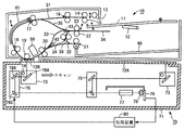
図15は、読み取り部としてのCIS50を用いた読み取り構造を説明するための図である。
図15に示すように、CIS50は、プラテンロール19とアウトロール20との間に設けられる。原稿の片面(第1面)は、第2プラテンガラス72Bに押し当てられ、この第1面の画像はCCDイメージセンサ78にて読み込まれる。
一方、CIS50では、原稿を搬送する搬送路を介して対向する他方の側から、片面(第2面)の画像が読み込まれる。
このCIS50は、ガラス51と、このガラス51を透過して原稿の第2面に光を照射するLED(Light Emitting Diode)52と、LED52からの反射光を集光するレンズアレイであるセルフォックレンズ53と、このセルフォックレンズ53により集光された光を読み取るラインセンサユニット54を備えている。
FIG. 15 is a diagram for explaining a reading structure using the
As shown in FIG. 15, the
On the other hand, in the
The
ラインセンサユニット54としては、CCDやCMOSセンサ、密着型センサ等を用いることができ、実寸幅(例えばA4長手幅297mm)の画像を読み取ることが可能である。
CIS50では、縮小光学系を用いずに、セルフォックレンズ53とラインセンサユニット54を用いて画像の取り込みを行うことから、構造をシンプルにすることができ、且つ、筐体を小型化し、消費電力を低減することができる。
尚、カラー画像を読み込む場合には、LED52にR(赤)G(緑)B(青)の3色のLED光源を組み合わせ、ラインセンサユニット54としてRGB3色用の3列一組のセンサを用いれば良い。
As the
In the
When reading a color image, the
また、CIS50による画像読み取りに際して、この読み取り部を構成する搬送路に、CIS50の筐体から延びる制御部材55、制御部材55によって押し付けられた原稿を突き当てる突き当て部材60を備えている。
ただし、制御部材55はCIS50を介して原稿送り装置10(図14参照)に取り付けられているが、突き当て部材60はスキャナ装置70(図14参照)に取り付けられている。
また、この突き当て部材60の下流側にはガイド部材61が設けられ、このガイド部材61と突き当て部材60との間には開口部63を構成し、更に、ガイド部材61の下部であって開口部63に連続する箇所には、原稿の表面に付着してきたごみや汚れを溜める回収部としてのごみ溜め部62が設けられている。
制御部材55および突き当て部材60は、原稿の搬送路に直交する方向に(即ち、原稿送り装置の前面から後面の方向に)、原稿送り装置10の前面から後面まで、搬送路の位置に対応して設けられている。
In addition, when the image is read by the
However, while the
Further, a
The
ここで、制御部材55は、CIS50に設けられた軸50aに巻き回されたくの字状の板金からなる板バネにて構成されており、制御部材55を撓み自在とすることで、搬送されてくる原稿の厚み分を吸収できると共に、折り曲げ痕のついた原稿であっても安定して搬送できるようになっている。
また、制御部材55の先端側は、CIS50による読み取り位置近傍まで伸びており、原稿と接触する部位にはヘミング曲げされた折り部55aが設けられ、原稿とスムーズに接触し、紙粉等の発生を防止できるようになっている。
なお、制御部材55の折り部55aと突き当て部材60との距離(原稿を通すためのギャップ)は0.1〜1.0mm程度に設定される。
Here, the
Further, the front end side of the
The distance between the
一方、突き当て部材60は、原稿の搬送方向上流側に設けられ、搬送される原稿を案内する搬送面60aと、この搬送面60aよりも原稿の搬送方向下流側に搬送面60aよりも一段下げて形成される段差面60bとを有している。
また、この段差面60bは、セルフォックレンズ53による光のフォーカスポイントの延長線と対向するように形成されており、段差面60b上には、二軸延伸ポリエステルフィルムからなる白基準部材としての白基準テープ64が貼り付けられている。
したがって、白基準テープ64は、突き当て部材60を介してスキャナ装置70に取り付けられていることになる。白基準テープ64の上面が、搬送路に露出した状態で配置されている。
On the other hand, the abutting
Further, the
Therefore, the
CIS50は、光学結像レンズにセルフォックレンズ53を採用していることから、焦点(被写界)深度が±0.3mmと浅く、スキャナ装置70側と比べて約1/13以下となっている。
このため、CIS50による読み取りに際しては、原稿の読み取り位置を所定の狭い範囲内に定めることが要求される。
そこで、上述した制御部材55を設け、原稿を制御部材55によって突き当て部材60に押し当てながら搬送し、プラテンロール19とアウトロール20との間にある原稿の姿勢を安定的に制御できるように構成した。
図15の一点鎖線矢印は、制御部材55を設けた場合における原稿の動きを示したものである。
制御部材55により、原稿が突き当て部材60に突き当てられながら搬送されていることが理解される。
このようにすることで、読み取り位置における原稿の高さを略一定にすることができ、被写界深度の浅いCIS50を用いた場合におけるピントの甘さを改善することが可能となっている。
Since the
For this reason, when reading by the
Therefore, the above-described
The one-dot chain line arrow in FIG. 15 shows the movement of the document when the
It is understood that the document is conveyed while being abutted against the abutting
In this way, the height of the document at the reading position can be made substantially constant, and the sweetness of the focus when using the
上記原稿送り装置10は、読取部を固定し、原稿を移動させながら原稿画像を読み取る両面原稿読取装置であり、上記スキャナ装置70は、原稿を固定した状態で光学系を走査することにより原稿を読み取る第2の読取装置に該当する。
この装置を用いれば、CCDイメージセンサにより原稿の第1面の読み取りを行う原稿の搬送時に、同時(時間の完全一致ではなく、同一の原稿搬送時程度の意味)にCISによって、原稿の第2面の読み取りを行うことが可能である。
即ち、CCDイメージセンサとCISとを用いて、搬送路への原稿の一度の搬送で、この原稿における表裏両面の画像を読み取ることを可能にすることができる。
The
When this apparatus is used, the second image of the original is read by CIS simultaneously with the conveyance of the original for reading the first side of the original by the CCD image sensor (meaning the time of the same original conveyance, not the exact time coincidence). It is possible to read the surface.
In other words, using the CCD image sensor and the CIS, it is possible to read the images on both the front and back sides of the document with a single conveyance of the document to the conveyance path.
なお、原稿を固定した状態で走査し、縮小光学系を用いて読み取る際は、両面原稿読取装置のうち、CCDイメージセンサで画像を読み取る際に使用するCCDセンサと共通のセンサを使用している。
ここで用いられているCISとは、近年装置の小型化を目的として、形状の小さい発光ダイオード(Light Emitting Diode:LED)を光源に利用し、レンズを介してリニアセンサで画像を直接読み取るコンタクトイメージセンサ(Contact Image Sensor:CIS)と呼ばれるものである。
上記画像読取装置では、モノクロスキャナとしての読み取りであるが、カラー画像を読み込む場合には、LEDにR(赤)G(緑)B(青)の3色のLED光源を組み合わせ、ラインセンサユニットとしてRGB3色用の3列一組のセンサを用いれば良い。
また必ずしも照明光源としてLEDを使う必要はないので、キセノン光源などを照明光源としてもよい。
When scanning with a fixed original and reading using a reduction optical system, a sensor common to the CCD sensor used when reading an image with a CCD image sensor is used in the double-sided original reading device. .
The CIS used here is a contact image that uses a light emitting diode (LED) having a small shape as a light source for the purpose of downsizing the apparatus in recent years, and directly reads an image with a linear sensor through a lens. This is called a sensor (Contact Image Sensor: CIS).
In the above image reading apparatus, reading is performed as a monochrome scanner. However, when reading a color image, LED light sources of three colors of R (red), G (green), and B (blue) are combined with an LED to form a line sensor unit. A set of sensors for three columns for RGB three colors may be used.
Further, since it is not always necessary to use an LED as the illumination light source, a xenon light source or the like may be used as the illumination light source.
上記CISに用いられているイメージセンサとしては、通常、図6に示すような複数のチップセンサを一方向に並べたものが使用されている。
図6には、1ラインの中に9つのセンサが並んだものが3ライン示されているが、この数はもちろん9つに限定されるものではない。
実際には、一つのチップが300画素前後で構成され、25個程度のチップでA4サイズの長手方向に相当するスキャナが較正される。
なお、図6中の3ラインのセンサは、R、G、Bの各信号を読み取るセンサに該当する。
図6でLで示しているものがマルチチップセンサを構成する一つのセンサチップの幅である。このチップ幅の単位で読取特性が変化するため、このようなマルチチップイメージセンサで読み取りを行うと、その変化が著しく大きい場合は、図7に示すような縦縞模様が発生するという異常画像になる。
As the image sensor used in the CIS, a plurality of chip sensors as shown in FIG. 6 are usually arranged in one direction.
FIG. 6 shows three lines in which nine sensors are arranged in one line, but this number is of course not limited to nine.
Actually, one chip is composed of about 300 pixels, and a scanner corresponding to the longitudinal direction of A4 size is calibrated with about 25 chips.
6 corresponds to a sensor that reads R, G, and B signals.
What is indicated by L in FIG. 6 is the width of one sensor chip constituting the multi-chip sensor. Since the reading characteristics change in units of the chip width, when reading is performed with such a multi-chip image sensor, if the change is extremely large, an abnormal image in which a vertical stripe pattern as shown in FIG. 7 is generated is obtained. .
それを防ぐために、各チップ間の特性差を吸収するような色空間変換を行う技術が開示されている。
このような技術を使うことで、既述のような激しい色むらが発生することは抑えることができる。
しかしながら、そのような技術でも100%特性を一致させる事はできる訳ではない。
その場合、人間の視覚特性としても最も敏感な付近を中心に色むらが顕在化してしまう事がある。
例えば、複数のセンサチップにまたがる程度の一様な領域がある原稿を読み取った時、その領域が濃い青のような有彩原稿だったとすると、ある青色の近くに少し色の違う青が存在したとしても、よく視認できない事がある。
あるいは視認されたとしても違和感を感じにくい。
In order to prevent this, a technique for performing color space conversion that absorbs a characteristic difference between chips has been disclosed.
By using such a technique, it is possible to suppress the occurrence of intense color unevenness as described above.
However, even with such a technique, it is not possible to match the 100% characteristics.
In such a case, uneven color may be manifested around the most sensitive area of human visual characteristics.
For example, when a document with a uniform area that spans multiple sensor chips is scanned, if that area is a chromatic original like dark blue, there is a slightly different blue color near a certain blue color. However, it may not be visible.
Or even if it is visually recognized, it is difficult to feel uncomfortable.
ところが、原稿が無彩であったとすると、同程度の色の差だったとしても、かたや無彩が再現されているのに対し、隣のセンサチップで読み取った領域では少し色づいている場合は、人間の視覚特性として非常に視認されやすく、また視認された場合には違和感を感じやすい。
色むらが目立ちやすい領域というのは低彩度領域であり、実際に無彩部で色づきが目立っている場合でも、彩度を測定すると数値としてはおよそ3〜4程度の値となっている(最も彩度が高い場合は255)。
したがって、低彩度領域のみ彩度を落とし、それ以外の部分については彩度を保存するような処理をかけることにより、色再現を殆ど損なわない状態で、マルチチップイメージセンサの各チップ間の特性ばらつきに基づく、読み取り画像の色むらを抑制することができる。
However, if the manuscript is achromatic, even if the color difference is the same level, the color is slightly reproduced in the area read by the adjacent sensor chip, while the color and color are reproduced. It is very easy to be visually recognized as human visual characteristics, and when it is visually recognized, it is easy to feel uncomfortable.
A region where color unevenness is conspicuous is a low saturation region, and even when coloring is actually conspicuous in an achromatic portion, the value is about 3 to 4 when the saturation is measured ( 255) when saturation is highest.
Therefore, by reducing the saturation only in the low-saturation region and applying a process that preserves the saturation in the other parts, the characteristics between each chip of the multi-chip image sensor can be obtained with almost no loss of color reproduction. Color unevenness of the read image based on the variation can be suppressed.
具体的には、図4に示したグラフに基づく値を備えた彩度変換テーブルを参照し、既に説明したような処理を行えば良い。
図4に示すグラフで、Climは入力された画像の彩度データのうち、彩度を落とす処理を行う限界値を示している。そして、これよりも高い彩度の画素に対しては、彩度を落とす処理を施さない。
なお、基本的に、この実施例における彩度調整処理は、本来の有彩領域に対して施してしまうと色再現を劣化させる方向の処理である。
彩度が比較的高いところで極端に彩度を落としてしまえば、マルチチップセンサの各チップ間の特性ばらつきに基づく色むらを抑制する効果よりも、本来の目的である色再現が達成できなくなってしまう。
Specifically, the processing described above may be performed with reference to the saturation conversion table having values based on the graph shown in FIG.
In the graph shown in FIG. 4, Clim indicates a limit value for performing a process of reducing the saturation in the saturation data of the input image. Then, a process for reducing the saturation is not performed on pixels having a higher saturation.
Basically, the saturation adjustment processing in this embodiment is processing in a direction in which color reproduction is deteriorated if it is applied to the original chromatic area.
If the saturation is extremely lowered at a relatively high saturation, the original color reproduction cannot be achieved rather than the effect of suppressing color unevenness based on the characteristic variation between chips of the multichip sensor. End up.
しかしながら、既述の通り、かなりの低彩度領域に対してのみ効かせる処理であるため、いわゆる鮮やかな色に対する影響はない。
但し、有彩画像の色再現の観点からすれば望ましい処理ではないため、メリットがない限りは処理を施さない方が良い。
一組のマルチチップセンサのバラツキは一定の範囲内でばらついたり、ユーザの求めるレベルは様々であるため、図4で彩度を落とし始める値として示したClimを、何段階か変更できるようにしておくことで、更にユーザの所望する画像を提供することができる。
However, as described above, since the processing is effective only for a considerably low saturation region, there is no influence on so-called vivid colors.
However, this is not a desirable process from the viewpoint of color reproduction of a chromatic image, so it is better not to perform the process unless there is a merit.
Since the variation of a set of multi-chip sensors varies within a certain range and the level required by the user varies, the Clim shown as the value at which the saturation starts to be lowered in FIG. 4 can be changed in several stages. Thus, an image desired by the user can be further provided.
次に、何段階かで変更した時の彩度変換テーブルに格納する値の変化を示すグラフ例を、図8及び図9に示す。
ここでClimの値が大きくなるほど、彩度変換による影響が大きくなってくる。
マルチチップイメージセンサのチップ間の特性ばらつきが大きい場合には、図9に示すようにClimが大きい設定を採用し、バラツキが小さい場合には、図8に示すようにClimが小さい設定を採用すれば良い。
図9に示すような設定をすると、画像の色むらが目立ちにくくなり、無彩原稿の色再現がよくなる一方で、有彩原稿の色再現が悪くなってくる。
ユーザは、無彩原稿の色むらとして許容できるレベルのClimに最も近い設定を行い、それよりClimを上げることは避けるべきである。
また、この実施例では図4、図8、図9の3段階の例を示したが、段階は3に限るものではなく、Climの値をより細かく複数段階に設定できるようにしても良い。
Next, examples of graphs showing changes in values stored in the saturation conversion table when changed in several stages are shown in FIGS.
Here, the greater the value of Clim, the greater the effect of saturation conversion.
When the characteristic variation between chips of the multi-chip image sensor is large, a setting with a large Clim is adopted as shown in FIG. 9, and when the variation is small, a setting with a small Clim is adopted as shown in FIG. It ’s fine.
If the setting as shown in FIG. 9 is performed, the color unevenness of the image is less noticeable, and the color reproduction of the achromatic document is improved, while the color reproduction of the chromatic document is deteriorated.
The user should make a setting closest to the level of Clim that can be tolerated as color unevenness of an achromatic document, and avoid raising Clim beyond that.
Further, in this embodiment, the example of the three steps of FIGS. 4, 8, and 9 is shown, but the number of steps is not limited to three, and the value of Clim may be set more finely in a plurality of steps.
次に、システム構成例について述べる。
この実施例においては、以下の(1)〜(3)に示す3種類の読取処理方法がある。(2)(3)については、共通のCCDセンサで画像を読み取っている。
(1)ADFを用いて原稿を移動しながら両面原稿の画像を読み取るとき、マルチチップイメージセンサを用いて画像を読み取る場合。
(2)ADFを用いて原稿を移動しながら両面原稿の画像を読み取るとき、CCDセンサを用いて画像を読み取る場合。
(3)原稿を固定した状態で縮小光学系を用いて画像を読み取るとき、CCDイメージセンサで画像を読み取る場合。CCDセンサと共通のセンサを使用している。
Next, a system configuration example will be described.
In this embodiment, there are three types of reading processing methods shown in the following (1) to (3). (2) For (3), an image is read by a common CCD sensor.
(1) When reading an image of a double-sided original while moving the original using ADF, and reading an image using a multichip image sensor.
(2) When reading an image of a double-sided original while moving the original using ADF, and reading an image using a CCD sensor.
(3) When reading an image with a CCD image sensor when reading an image using a reduction optical system with the document fixed. The same sensor as the CCD sensor is used.
(第1のシステム例)
先程述べたように、有彩画像の色再現の観点から、この実施例で行っている彩度の低減処理は、本来の色からすれば原稿忠実の狙いからは異なり、望ましい処理ではないため、メリットがない限りは処理を施さない方が良い。
最もシンプルに考えた場合、マルチチップイメージセンサに起因する色むらを抑制する処理は、(1)の場合にのみ適用するのが良いと考えられる。
CCDイメージセンサには、このような色むらは存在しない。色むらを抑制する訳でもなく、色再現に対するデメリットのみが存在する。
(First system example)
As described above, from the viewpoint of color reproduction of a chromatic image, the saturation reduction processing performed in this embodiment differs from the original faithful aim from the original color and is not a desirable processing. Unless there is merit, it is better not to process.
In the simplest case, it is considered that the process for suppressing the color unevenness caused by the multichip image sensor should be applied only in the case of (1).
Such color unevenness does not exist in the CCD image sensor. There is only a demerit for color reproduction, not suppressing color unevenness.
本実施例の場合は、両面原稿読取部101から、CCD読取の画像とCIS読取の画像がメモリ制御により交互にスキャナ補正部104に送出されてくる。
CIS読取の画像に対しては、既述の通り、図4に示す値を備えた彩度変換テーブルを設定する。
CCD読取の画像に対しては、図10に示す値を備えた彩度変換テーブルを設定する。
図10は、Clim=0の場合に相当し、彩度調整処理を一切行わない設定に該当する。これらの設定を、メモリ制御に同期して行う。
In the case of the present embodiment, the double-sided
As described above, a saturation conversion table having values shown in FIG. 4 is set for the CIS-read image.
For a CCD read image, a saturation conversion table having values shown in FIG. 10 is set.
FIG. 10 corresponds to a case where Clim = 0, and corresponds to a setting in which no saturation adjustment processing is performed. These settings are performed in synchronization with the memory control.
(第2のシステム例)
しかしながら、両面で原稿を読み取った場合、原稿のある一方の面と、その裏面とでは最終的にユーザが手にする画像がほぼ同じであることが理想的であると考えられる。
したがって、両面原稿読取部101において原稿を読み取った場合は、両面で同じような画像を得ることを欲するユーザにとって(1)(2)の双方について同等の処理をかけるのが望ましいと言える。
このような要求のユーザに対しては、原稿の表面と裏面に対して同一の彩度変換テーブルを用いた彩度調整処理によって彩度調整を行うような画像処理装置を提供することが望ましい。
(Second system example)
However, when the original is read on both sides, it is ideal that the image finally obtained by the user is substantially the same on one side of the original and the back side.
Therefore, when a document is read by the double-sided
It is desirable to provide an image processing apparatus that performs saturation adjustment by saturation adjustment processing using the same saturation conversion table for the front surface and the back surface of a document for a user who requests such a request.
この場合も、両面原稿を両面読取する訳ではなく、片面原稿のみの場合については、単純に(2)の読み取りが行われるだけである。
その場合は、CIS読取ではないため、色むら抑制のための彩度調整処理を行う必要はない。
したがって、原稿が片面か両面かによって、彩度調整による色むら抑制を行うか否かを切り替えた方が良いと考えられる。
したがって、ユーザが両面原稿読取を図示しない操作画面から指定した時のみ、図4に示した値を備えた彩度変換テーブルを設定する。それ以外では、図10に示した値を備えた彩度変換テーブルを設定する。
なお、同じADFによる表面読取にも関わらず、片面読取と両面読取とで差が出ることを好まないユーザのために、片面読取でも彩度調整を効かせるようにしても良い。
In this case as well, the double-sided original is not double-sided read, and only the single-sided original is read in (2).
In this case, since CIS reading is not performed, it is not necessary to perform saturation adjustment processing for suppressing color unevenness.
Therefore, it is considered better to switch whether or not to suppress color unevenness by adjusting the saturation depending on whether the original is single-sided or double-sided.
Therefore, the saturation conversion table having the values shown in FIG. 4 is set only when the user designates double-sided document reading from an operation screen (not shown). In other cases, a saturation conversion table having the values shown in FIG. 10 is set.
It should be noted that for users who do not like the difference between single-sided scanning and double-sided scanning in spite of surface scanning by the same ADF, saturation adjustment may be applied to single-sided scanning.
(第3のシステム例)
さらに、実際のユーザの用途としては、(3)のように原稿固定の方式で読み取る場合も多い。この場合は、(1)(2)の方式で読み取った画像と比較をするというよりは、(3)の単体で原稿忠実な画像が求められると考えられる。
したがって、そのような用途の場合は、(3)の画像で不必要に本実施例で行っている彩度調整処理は行わない。このような場合(いわゆるブック読取の場合)は、図10に示す値を備えた彩度変換テーブルを設定する。
(Third system example)
Furthermore, as an actual user's application, there are many cases where the original is fixed and read as shown in (3). In this case, it is considered that an original image faithful to the original of (3) is required rather than comparing with the image read by the methods (1) and (2).
Therefore, in such an application, the saturation adjustment processing that is unnecessarily performed in the present embodiment is not performed on the image of (3). In such a case (so-called book reading), a saturation conversion table having values shown in FIG. 10 is set.
(第4のシステム例)
上述のシステム構成を示してきたが、実際にはユーザの要求により最適なシステムは異なる。
ユーザに提供する装置として、最もユーザが欲していると考えられるシステムに固定化する方法もあるが、複数のシステムを可変に提供することができれば、なお望ましい。
図11に示すのは、上記(1)〜(3)の読取処理方法に対し、図4に示す値を備えた低彩度部の彩度低下を加える彩度変換テーブルを設定して彩度調整処理をする場合を彩度調整“オン(ON)”で表し、図10に示す値を備えた彩度変換テーブルを設定し、彩度調整処理を行わない場合を彩度調整“オフ(OFF)”で表している。
(Fourth system example)
Although the system configuration described above has been shown, the optimum system differs depending on the user's request.
As a device provided to the user, there is a method of fixing it to a system that the user most desires, but it is still desirable if a plurality of systems can be variably provided.
FIG. 11 shows a saturation conversion table for setting the saturation reduction of the low saturation portion having the values shown in FIG. 4 with respect to the reading processing methods (1) to (3) described above. The case where the adjustment process is performed is represented by saturation adjustment “ON”, the saturation conversion table having the values shown in FIG. 10 is set, and the case where the saturation adjustment process is not performed is set to “OFF” (OFF). ) ”.
まず、図11に示す第1設定について説明する。
この第1設定の場合は、全ての場合に彩度調整をオンにして色むら抑制処理を実施している。
本来(2)(3)には彩度調整処理が必要ないと考えられるが、どの読取処理方法で読み取っても、全て一貫した画像を得ることができる。
但し、低彩度領域の画像に対しては、原稿忠実の画像よりも彩度が落ちてしまったり、グラデーションの階調性が若干落ちてしまう。
極めて厳密な色再現を求めるユーザには適さないこともあるが、一般のユーザにとっては、低彩度部における大きな色むらの方が許容されない場合がしばしばある。
このように、第1の設定は、低彩度部について多少の色再現を犠牲にしても構わないユーザには事実上問題ない画像を提供することができる。
First, the first setting shown in FIG. 11 will be described.
In the case of this first setting, the saturation adjustment is turned on in all cases and the uneven color suppression process is performed.
Originally, it is considered that the saturation adjustment processing is not necessary for (2) and (3), but a consistent image can be obtained by any reading processing method.
However, the saturation of the image in the low saturation region is lower than that of the original faithful image, and the gradation of gradation is slightly deteriorated.
Although it may not be suitable for users who require extremely strict color reproduction, for general users, large color unevenness in the low saturation portion is often not allowed.
In this way, the first setting can provide an image that is practically satisfactory to a user who may sacrifice some color reproduction for the low saturation portion.
次に、第2設定について説明する。
この第2設定の場合は、原稿固定の読取方式の時のみ、彩度調整をオフにして色むら抑制処理を実施しない。
これにより、ADFによる両面原稿読取を行った場合は、表面と裏面に一貫性が保たれる。
ADF読取にて彩度調整処理による副作用が問題となる場合は、原稿固定の読取方式で読み取りを行えば良い。
但し、片面原稿を原稿固定の読取方式で読み取った場合とADFで読み取った場合に、低彩度部で差分が発生する。
このように、第2の設定は、両面原稿の表裏の差に重点を置くユーザに適した設定である。
Next, the second setting will be described.
In the case of this second setting, the saturation adjustment is turned off and color unevenness suppression processing is not performed only in the case of the original fixed reading method.
Thereby, when double-sided original reading is performed by ADF, consistency is maintained on the front surface and the back surface.
When the side effect due to the saturation adjustment process becomes a problem in ADF reading, reading may be performed by a reading method fixed to the original.
However, a difference occurs in the low saturation portion when a single-sided original is read by a reading method fixed to the original and when it is read by ADF.
As described above, the second setting is a setting suitable for the user who places emphasis on the difference between the front and back of the double-sided document.
次に、第3設定について説明する。
この第3設定の場合は、両面原稿読取部のCISを使った読み取りを行う時のみ、彩度調整をオンにして色むら抑制処理を実施する。
これにより、本質的に必要な場合のみ彩度調整による色むら抑制処理を行うことができ、CCDセンサを使った読み取りでは、不必要な画像劣化を防ぐことができる。
また、片面原稿を原稿固定の読取方式で読み取った場合とADFで読み取った場合とで、彩度調整処理に基づく画像の差分は発生しない。
但し、両面原稿読取時には、表面と裏面とで差分が発生する。
このように、第3の設定は、両面読取時の裏面画像には、多少の画質劣化を許容できるようなユーザに適した設定である。
Next, the third setting will be described.
In the case of the third setting, only when performing reading using the CIS of the double-sided document reading unit, the saturation adjustment is turned on and the uneven color suppression process is performed.
As a result, color unevenness suppression processing by saturation adjustment can be performed only when it is essentially necessary, and unnecessary image deterioration can be prevented in reading using a CCD sensor.
In addition, there is no difference in the image based on the saturation adjustment processing between when the single-sided original is read by the original fixed reading method and when it is read by the ADF.
However, when reading a double-sided document, a difference occurs between the front side and the back side.
As described above, the third setting is a setting suitable for a user who can tolerate a slight deterioration in image quality in the back side image at the time of duplex scanning.
最後に、第4設定について説明する。
この第4設定の場合は、彩度調整をオフにして色むら抑制処理を常に実施しない。
従って、低彩度部に色むらが発生するという異常が見られるが、そのような彩度領域を含まない原稿を読み取る場合には、この第4設定でも問題ない。
むしろ、第4設定によれば、原稿に忠実な色再現を常に求めることができる。
そこで、通常はこの第4設定にしておき、必要に応じて第1〜第3設定の各設定にそれぞれ切り替える使い方も考えられる。
そのような切り替えが煩雑で手間であるというユーザは、用途に応じてデフォルトを第1〜第4設定のいずれかに設定しておけば良い。
なお、ここでは第1〜第4設定を行う実施例を示したが、(1)〜(3)に対してこれ以外の“OFF”“ON”の組み合わせを設定できるようにしても良い。
Finally, the fourth setting will be described.
In the case of the fourth setting, the saturation adjustment is turned off and the uneven color suppression process is not always performed.
Therefore, although there is an abnormality that color unevenness occurs in the low saturation portion, this fourth setting is not a problem when reading a document that does not include such a saturation region.
Rather, according to the fourth setting, color reproduction faithful to the original can always be obtained.
Therefore, it is also conceivable to use the fourth setting in general and switch to the first to third settings as necessary.
A user who is troublesome and troublesome to perform such switching may set the default to one of the first to fourth settings according to the application.
Although the first to fourth settings are shown here, other combinations of “OFF” and “ON” may be set for (1) to (3).
また、ここではADFの表面読取画像と裏面読取画像を交互にスキャナ補正部に入力し、適切なパラメータを各々それに同期する形で設定する実施例を示したが、スキャナ補正部や圧縮処理部を二つもち、独立にパラメータ設定を行う実施例も考えられる。
その場合は、両面原稿読取時にパラメータを交互に切り替える訳ではなく、2つのデバイスにパラメータを適切に設定することになる。
この場合も、本発明に係る部分の本質は同じであり、色むら抑制処理を行いたい画像パスにおいては図4に示した値を備えた彩度変換テーブルを設定し、色むら抑制処理を行わない画像パスには図10に示した値の彩度変換テーブルを設定すればよい。
In this embodiment, the front side scanned image and the back side scanned image of the ADF are alternately input to the scanner correction unit, and appropriate parameters are set in synchronization with each other. However, the scanner correction unit and the compression processing unit are provided. There are two embodiments in which parameter setting is performed independently.
In this case, the parameters are not switched alternately when reading a double-sided document, but the parameters are set appropriately for the two devices.
In this case as well, the essence of the portions according to the present invention is the same, and in the image path where the color unevenness suppression process is desired, the saturation conversion table having the values shown in FIG. 4 is set and the color unevenness suppression process is performed. A saturation conversion table having the values shown in FIG.
これまで述べてきたシステムにおいては、ユーザーがカラーモード等の出力モードを設定した時でも、同一の彩度変換テーブルがかけられていた。
しかしながら、実際には出力用途に応じてその色むら抑制処理の実施は変えるべきものである。
例えば、カラーモードについて考える。
モノクロモードで画像データを出力する際には、元々彩度情報が出力画像に残っていないため、マルチチップのデバイス色空間が彩度方向にずれていたとしても、あまり目立たない。
ところが、彩度調整処理自体も、完全に彩度情報のみを調整する訳ではなく、明度方向のデータも幾らか変化してしまう。
In the systems described so far, the same saturation conversion table is applied even when the user sets an output mode such as a color mode.
However, in practice, the color unevenness suppression process should be changed according to the output application.
For example, consider the color mode.
When image data is output in the monochrome mode, the saturation information originally does not remain in the output image, so even if the multi-chip device color space is shifted in the saturation direction, it is not very noticeable.
However, the saturation adjustment process itself does not completely adjust only the saturation information, and the data in the brightness direction also changes somewhat.
特にハード規模を意識して簡易的な式で実装するとその程度は大きくなる。
このように、モノクロモードで画像データを出力する場合は、彩度調整による色むら抑制処理を行うメリットよりもデメリットが発生する可能性が大きくなることがある。
したがって、ユーザが操作表示部115の操作画面でモノクロモードを指定した場合には、これまで述べてきた実施例において、彩度調整オンの設定となっている場合でも、必ず色むら抑制処理を実施しないで出力する方が、ユーザにとって望ましい画像になる。
また、カラーモードが自動カラー判定モードに指定されている場合は、原稿がカラー原稿と判定された時のみ色むら抑制処理補正を実施して出力すれば良い。
次に、画質モードの変更に対応するCISの色むら抑制処理の対応について考える。
In particular, if the implementation is implemented with a simple formula in consideration of the hardware scale, the degree will increase.
As described above, when image data is output in the monochrome mode, there is a possibility that a demerit may occur more than a merit of performing color unevenness suppression processing by saturation adjustment.
Therefore, when the user designates the monochrome mode on the operation screen of the
Further, when the color mode is designated as the automatic color determination mode, color unevenness suppression processing correction may be performed and output only when the document is determined to be a color document.
Next, consideration will be given to the CIS color unevenness suppression process corresponding to the change of the image quality mode.
例えば、細かい色再現が求められず、とにかくチップ幅の色むらのような異常画像を避けたい場合には、CISの色むら抑制処理を実施して、比較的彩度の高いところから彩度を落とし始めるように、図9に示した彩度変換テーブルを設定するとよい。
また、写真モードの場合は、正確なグラデーションの再現が求められるような事も多いため、CISの色むら抑制処理を実施しないようにするか、あるいは、色むら抑制処理を実施しても比較的彩度の低いところまで彩度を落とさないように、図8に示した彩度変換テーブルを設定するとよい。
無論、必ずこの設定の仕方が望まれるとは限らないので、上述とは異なる設定にしても良い。
For example, if fine color reproduction is not required, and you want to avoid abnormal images such as chip-wide color unevenness anyway, perform CIS color unevenness suppression processing to reduce the saturation from a relatively high saturation point. It is preferable to set the saturation conversion table shown in FIG.
In the case of the photo mode, accurate gradation reproduction is often required. Therefore, the CIS color unevenness suppression process is not performed or the color unevenness suppression process is relatively performed. It is preferable to set the saturation conversion table shown in FIG. 8 so that the saturation is not lowered to a low saturation level.
Of course, this setting method is not always desired, so it may be set differently from the above.
次に、コピー装置として使用する場合と、スキャナ配信装置として使用する場合の違いについて考える。
色補正部123は、出力される色空間に応じてパラメータを切り替え、紙出力に最適な色空間に補正をしたり、sRGB空間において最適な色空間に補正を行ったりしている。
それは、色域の違いやガマット圧縮の仕方の違いがあるため(例えば、プリンタが画像出力に使用するシアン(C),マゼンタ(M),イエロー(Y),ブラック(Bk)というガマットと、ディスプレイで使われるsRGBのガマットとは異なる)、同一の原稿を読み取っても、全く同じ色再現となる訳ではないからである。
例えば、無彩原稿がデバイス色空間の違いにより色づいてしまった場合の色むらの目立つ程度も、紙出力とスキャナ配信で得られた電子画像とでは異なるものである。
したがって、その出力先の色空間に応じて、色むら補正に用いる彩度変換テーブルの最適設定は異なる。
Next, let us consider the difference between using as a copying apparatus and using as a scanner distribution apparatus.
The
This is because there are differences in color gamut and gamut compression (for example, gamuts of cyan (C), magenta (M), yellow (Y), black (Bk) used by the printer for image output, and display) This is because even if the same document is read, the color reproduction is not exactly the same.
For example, the degree to which color unevenness is noticeable when an achromatic document is colored due to a difference in device color space differs between paper output and an electronic image obtained by scanner distribution.
Therefore, the optimum setting of the saturation conversion table used for color unevenness correction differs depending on the output destination color space.
すなわち、スキャナの画像読み取り直後に彩度がAであった場合、紙出力に最適な色空間に色補正部123で変換した結果がA′であったとしても、ディスプレイに表示させたときの見え方が最適な色空間(sRGB空間)になるように色補正部123で変換した結果は一般にA′とはならずにA″という別の値になる。
このような結果を、入力彩度が異なる場合に彩度方向に対してプロットすると、図12に示すような結果が得られる。
例えば、図12中に実線で示す曲線が入力画像をsRGB空間に変換した場合の値の変を示し、点線で示す曲線が紙出力に最適な色空間に変換した場合の値の変化を示している。
That is, when the saturation is A immediately after the image is read by the scanner, even if the result of conversion by the
When such a result is plotted with respect to the saturation direction when the input saturation is different, the result shown in FIG. 12 is obtained.
For example, a curve indicated by a solid line in FIG. 12 indicates a change in value when the input image is converted to sRGB space, and a curve indicated by a dotted line indicates a change in value when converted to a color space optimal for paper output. Yes.
この実施例では、sRGB空間の方が紙出力最適な色空間よりも彩度が高まりやすい空間であるものと仮定する。
この仮定の場合、上述したいずれの場合も無彩部の色づきが目立たなくなる範囲まで彩度を落とすには、sRGB空間の方が紙出力最適な色空間よりも大きく彩度を落とす必要がある。
したがって、図4に示した彩度変換テーブルが紙出力に最適な色空間用の彩度変換テーブルであるとすると、sRGB空間で同等の彩度調整処理をするには、図13に示すような彩度変換テーブルによる彩度調整処理を行う必要がある。
In this embodiment, it is assumed that the sRGB space is a space in which the saturation is likely to be higher than the color space that is optimal for paper output.
In this case, in any of the cases described above, in order to reduce the saturation to a range where the coloring of the achromatic portion becomes inconspicuous, it is necessary to reduce the saturation in the sRGB space larger than the color space optimal for paper output.
Accordingly, assuming that the saturation conversion table shown in FIG. 4 is a color space saturation conversion table that is optimal for paper output, in order to perform the same saturation adjustment processing in the sRGB space, as shown in FIG. It is necessary to perform saturation adjustment processing using a saturation conversion table.
次に、PC114からトウェインのような標準的なインタフェース仕様を通じてこのフルカラー画像処理装置にアクセスする場合を考える。
例えば、フォトショップのようなトウェイン対応の画像編集ソフトウェアを通じて、このフルカラー画像処理装置にスキャナ読み取り動作の指示を出し、読み取った画像データをPC114側に取り込む場合である。
トウェインドライバでは、PC114で起動しているトウェイン対応アプリケーションから画像の特性(階調数、解像度、明るさ、γ特性など)を変更できるようなインタフェースが提供される(図13参照)。
PC114からは、画像処理のかかっていない読み取り画像データを取得した上でユーザの側で適切に処理を行いたいという要求もあるため、設定によっては加工されていない読み取り画像データを求められることがある。
Next, consider the case where the
For example, this is a case where an instruction for a scanner reading operation is issued to the full-color image processing apparatus through Twain compatible image editing software such as Photoshop, and the read image data is taken into the
The Twain driver provides an interface that can change image characteristics (number of gradations, resolution, brightness, γ characteristics, etc.) from a Twain-compatible application running on the PC 114 (see FIG. 13).
Since there is a request from the
このような場合、彩度調整による色むら抑制処理は基本的にかけない設定とした方が良い。
但し、PC114のユーザがスキャナの無加工画像データを欲しかったとしても、チップ単位の色むらが欲しい訳ではない。
したがって、色むらを抑制することを重視する場合は、トウェインの時もカラー読み取りの場合は画像データの色むら抑制処理を実施するように設定しても良い。
最後に、EFI(=Extensible Firmware Interface)のような外部コントローラを通じて画像処理を行う場合、標準チャートをこのフルカラー画像処理装置のスキャナで読み取ることによりキャリブレーションを行うこともできる。
そのようなキャリブレーションを行う場合に、彩度が加工された画像で行うことは不適切と考えられる(純粋に読み取りデバイスのγ特性を知りたい場合など)。
したがって、このようなキャリブレーションを行う場合は、色むら抑制処理を実施しないように設定しておいた方が良い。
In such a case, it is better to set so that the uneven color suppression processing by saturation adjustment is basically not applied.
However, even if the user of the
Therefore, when importance is placed on suppressing color unevenness, it may be set so that color unevenness suppression processing of image data is performed both in Twain and in color reading.
Finally, when image processing is performed through an external controller such as EFI (= Extensible Firmware Interface), calibration can be performed by reading a standard chart with a scanner of the full-color image processing apparatus.
When performing such a calibration, it is considered inappropriate to use an image with saturation processed (for example, when it is desired to know the γ characteristic of the reading device purely).
Therefore, when performing such calibration, it is better to set so as not to perform the uneven color suppression process.
このように、マルチチップイメージセンサで画像の読み取りを行う場合でも、画像データの出力の条件、あるいは出力画像データの使用用途によっては、彩度調整を用いたCISの色むら抑制処理を行わない方が良い場合がある。
そして、上述のようにして、画像データの出力用途に応じて色むら抑制の処理を行うか否かを適切に設定することができるので、ユーザの所望する品質の画像データを提供することができる。
As described above, even when the image is read by the multichip image sensor, depending on the output condition of the image data or the usage of the output image data, the CIS color unevenness suppression process using the saturation adjustment is not performed. May be good.
In addition, as described above, whether or not to perform color unevenness suppression processing can be appropriately set according to the output use of the image data, so that it is possible to provide image data having a quality desired by the user. .
次に、この発明は、複数の機器(例えば、ホストコンピュータ、インタフェース機器、スキャナ、プリンタ、複写機、複合機を含む機器)から構成されるシステムに適用しても、1つの機器から構成される装置(例えば、ホストコンピュータ、インタフェース機器、スキャナ、プリンタ、複写機、複合機を含む機器)に適用しても良い。
また、上述したこの発明に係る機能を実現するプログラム(ソフトウェアのプログラムコード)を記録した記録媒体を、システムまたは装置に供給し、そのシステムまたは装置のコンピュータ(または、CPU、MPU、DSP)が記録媒体に格納されたプログラムを実行することによっても達成することが可能である。
この場合、記録媒体から読み出されたプログラム自体が上述した画像処理装置の各機能を実現することになり、そのプログラムまたはそのプログラムを記憶した記録媒体は本発明に係る構成に相当する。
Next, even if the present invention is applied to a system composed of a plurality of devices (for example, a device including a host computer, an interface device, a scanner, a printer, a copying machine, and a multi-function device), it is composed of one device. The present invention may be applied to an apparatus (for example, a device including a host computer, an interface device, a scanner, a printer, a copier, and a multifunction device).
In addition, a recording medium on which a program (software program code) for realizing the functions according to the present invention described above is recorded is supplied to the system or apparatus, and the computer (or CPU, MPU, DSP) of the system or apparatus records it. It can also be achieved by executing a program stored in a medium.
In this case, the program itself read from the recording medium realizes each function of the above-described image processing apparatus, and the program or the recording medium storing the program corresponds to the configuration according to the present invention.
上記プログラムコードを供給するための記録媒体としては、FD、ハードディスク、光ディスク、光磁気ディスク、CD−ROM、CD−R、磁気テープ、不揮発性のメモリ、ROMなどの光記録媒体、磁気記録媒体、光磁気記録媒体、半導体記録媒体を使用することができる。
また、コンピュータが読み出したプログラムを実行することにより、上述した画像処理装置の機能が実現されるだけでなく、そのプログラムの指示に基づき、コンピュータ上で稼働しているOS(オペレーティングシステム)などが実際の処理の一部または全部を行い、その処理によって上述した画像処理装置の機能が実現される場合も含まれることは言うまでもない。
As a recording medium for supplying the program code, an optical recording medium such as FD, hard disk, optical disk, magneto-optical disk, CD-ROM, CD-R, magnetic tape, nonvolatile memory, ROM, magnetic recording medium, A magneto-optical recording medium or a semiconductor recording medium can be used.
Further, by executing the program read by the computer, not only the functions of the above-described image processing apparatus are realized, but an OS (operating system) operating on the computer is actually executed based on the instruction of the program. It goes without saying that the case where the above-described processing of the image processing apparatus is realized by performing part or all of the above processing.
さらに、記録媒体から読み出されたプログラムが、コンピュータに挿入された機能拡張ボードやコンピュータに接続された機能拡張ユニットに備わるメモリに書き込まれた後、そのプログラムの指示に基づき、その機能拡張ボードや機能拡張ユニットに備わるCPU等が実際の処理の一部または全部を行い、その処理によって上述した画像処理装置の機能が実現される場合も含まれることは言うまでもない。 Furthermore, after the program read from the recording medium is written in a memory provided in a function expansion board inserted into the computer or a function expansion unit connected to the computer, the function expansion board or It goes without saying that the CPU or the like provided in the function expansion unit performs part or all of the actual processing, and the above-described functions of the image processing apparatus are realized by the processing.
この実施例は、彩度調整によって低彩度の画像信号に対してのみ彩度を落とす変換を行うことにより、マルチチップイメージセンサを構成するチップ幅の単位で発生する色むらを抑制することができる。
また、彩度を落とす彩度の上限を調整できるようにすることにより、本当に必要とする彩度領域においてのみ彩度を落とす事ができるようにすることができる。
さらに、両面原稿読取部において、片面をマルチチップイメージセンサ、他方の面をマルチチップでないイメージセンサ(例えば、CCDセンサ)で読み取る場合に、色むら抑制ができる彩度調整処理をマルチチップイメージセンサ側だけにかけることにより、CCD読取側の画像を不必要に変化させないようにすることができる。
In this embodiment, color unevenness generated in units of chip widths constituting a multi-chip image sensor can be suppressed by performing conversion that reduces saturation only for low-saturation image signals by saturation adjustment. it can.
In addition, by making it possible to adjust the upper limit of saturation for reducing saturation, saturation can be reduced only in a saturation region that is really necessary.
Further, in the double-sided document reading unit, when the one side is read by a multichip image sensor and the other side is read by a non-multichip image sensor (for example, a CCD sensor), saturation adjustment processing that can suppress color unevenness is performed on the multichip image sensor side. By applying only to this, it is possible to prevent the image on the CCD reading side from being changed unnecessarily.
また、両面原稿読取部において両面原稿を読む場合は、マルチチップイメージセンサ読取側の色むらを防ぐと共に、原稿の両面で彩度の変化が同じになるようにし、なおかつ片面読取時は、マルチチップでないイメージセンサ(例えば、CCDセンサ)のみで画像を取得して色むら抑制用の彩度調整処理を行わないことにより、CCD読取側の画像を不必要に変化させないようにすることができる。
さらに、両面原稿読取部(ADFタイプ)とブック読取部(コンタクトガラス上に原稿を固定し、スキャナでスキャンをする読取部)の双方を備える画像処理装置において、ADF読取の片方の面の読取(マルチチップイメージセンサを用いた読取)、ADF読取のもう一方の面の読取(マルチチップでない(例えばCCD)イメージセンサを用いた読取)、ブック読取(マルチチップでない(例えばCCD)イメージセンサを用いた読取)の3つの読取方法について、所望の彩度調整処理(色むらを抑制する、BOOKとADFで同等の画像を作る、ADFの表面と裏面とで同等の画像を作る等)をかけることができる。
When reading a double-sided document in the double-sided document reading unit, color unevenness on the multichip image sensor reading side is prevented, and the saturation change is the same on both sides of the document. It is possible to prevent the image on the CCD reading side from being unnecessarily changed by acquiring an image using only a non-image sensor (for example, a CCD sensor) and not performing saturation adjustment processing for suppressing color unevenness.
Furthermore, in an image processing apparatus including both a double-sided document reading unit (ADF type) and a book reading unit (a reading unit that fixes a document on a contact glass and scans it with a scanner), one side of ADF reading (reading) Reading using a multi-chip image sensor), reading the other side of ADF reading (reading using a non-multi-chip (eg CCD) image sensor), book reading (using a non-multi-chip (eg CCD) image sensor) For the three reading methods (reading), desired saturation adjustment processing (suppressing color unevenness, making an equivalent image with BOOT and ADF, making an equivalent image with the front and back surfaces of ADF, etc.) is applied. it can.
さらに、両面原稿読取部において両面原稿を読む場合は、マルチチップイメージセンサ読取側の色むらを防ぐが、ブック読取時は、マルチチップでないイメージセンサ(例えばCCDセンサ)のみで画像を取得して、色むら抑制用の彩度調整処理を行わないことにより、CCD読取側の画像を不必要に変化させないようにすることができる。
また、この実施例の画像処理装置を備えることにより、所望の画質を満たす画像形成装置を提供することができる。
さらに、プログラムコードの実行により、ファクシミリ装置、プリンタ、スキャナ、複写機、複合機、パーソナルコンピュータを含む装置に上述の機能を実現させることができる。
Furthermore, when reading a double-sided document in the double-sided document reading unit, color unevenness on the multi-chip image sensor reading side is prevented, but when reading a book, an image is acquired only by an image sensor (for example, a CCD sensor) that is not a multi-chip, By not performing saturation adjustment processing for suppressing uneven color, it is possible to prevent the image on the CCD reading side from being unnecessarily changed.
Also, by providing the image processing apparatus of this embodiment, an image forming apparatus that satisfies a desired image quality can be provided.
Furthermore, by executing the program code, the above-described functions can be realized in apparatuses including a facsimile machine, a printer, a scanner, a copier, a multifunction machine, and a personal computer.
この発明による画像処理装置と画像形成装置と画像処理方法とプログラムは、ファクシミリ装置、プリンタ、スキャナ、複写機、複合機、パーソナルコンピュータを含む装置において適用することができる。 The image processing apparatus, the image forming apparatus, the image processing method, and the program according to the present invention can be applied to apparatuses including a facsimile machine, a printer, a scanner, a copier, a multifunction peripheral, and a personal computer.
101:両面原稿読取部 102:第2画像読取部 103:メモリ 104:スキャナ補正部 105:圧縮処理部 106:メモリ制御部 107:プロッタ 108:プリンタ補正部 109:伸張処理部 110:コントローラ 111:HDD 112:NIC 113:汎用バス 115:操作表示部 120:スキャナγ補正部 121:彩度変換部 122:フィルタ処理部 123:色補正部 124:変倍処理部 125:像域分離部 130:RGB−Yuv変換部 131:彩度算出部 132:彩度変換テーブル 133:彩度補正部 134:Yuv−RGB変換部 140:プリンタγ補正部 141:階調処理部 101: Double-sided document reading unit 102: Second image reading unit 103: Memory 104: Scanner correction unit 105: Compression processing unit 106: Memory control unit 107: Plotter 108: Printer correction unit 109: Decompression processing unit 110: Controller 111: HDD 112: NIC 113: General-purpose bus 115: Operation display unit 120: Scanner gamma correction unit 121: Saturation conversion unit 122: Filter processing unit 123: Color correction unit 124: Scaling processing unit 125: Image area separation unit 130: RGB- Yuv conversion unit 131: saturation calculation unit 132: saturation conversion table 133: saturation correction unit 134: Yuv-RGB conversion unit 140: printer γ correction unit 141: gradation processing unit
Claims (10)
前記フルカラー画像読取手段によって読み取られた画像の画像信号に対して前記マルチチップイメージセンサを構成するチップ幅の単位で発生する色むらを抑制する色むら抑制手段と、
前記画像信号に対して指定された出力用途に応じて前記色むら抑制手段による抑制を実施するか否かを切り換える手段とを備えたことを特徴とする画像処理装置。 Full color image reading means comprising a multi-chip image sensor in which a plurality of image sensors for converting input light into electrical signals are arranged in one direction;
Color unevenness suppressing means for suppressing color unevenness generated in units of chip widths constituting the multichip image sensor with respect to an image signal of an image read by the full-color image reading means;
An image processing apparatus comprising: means for switching whether or not to perform suppression by the color unevenness suppression means in accordance with an output application designated for the image signal.
前記色むら抑制工程は、前記フルカラー画像読取手段によって読み取られた画像の画像信号から彩度データを算出する彩度算出工程と、前記彩度算出工程で算出された彩度データを用いて彩度を調整する彩度調整工程とを有し、前記彩度調整工程によって低彩度の画像信号に対してのみ彩度を落とす変換を行うことにより、マルチチップイメージセンサを構成するチップ幅の単位で発生する色むらを抑制する工程であることを特徴とする画像処理方法。 Chip width constituting the multi-chip image sensor with respect to the image signal of the image read by the full-color image reading means provided with a multi-chip image sensor in which a plurality of image sensors for converting input light into electrical signals are arranged in one direction A color unevenness suppressing step for suppressing color unevenness generated in units of and a step of switching whether or not to perform the suppression by the color unevenness suppressing step according to the output application specified for the image signal,
The color unevenness suppressing step includes a saturation calculation step of calculating saturation data from an image signal of an image read by the full-color image reading unit, and saturation using the saturation data calculated in the saturation calculation step. A saturation adjustment step for adjusting the image, and by performing conversion that lowers the saturation only for low-saturation image signals by the saturation adjustment step, in units of chip widths constituting a multi-chip image sensor. An image processing method, which is a step of suppressing color unevenness that occurs.
前記色むら抑制手順では、前記フルカラー画像読取手段によって読み取られた画像の画像信号から彩度データを算出する彩度算出手順と、前記彩度算出手順で算出された彩度データを用いて彩度を調整する彩度調整手順とを実施させ、前記彩度調整手順によって低彩度の画像信号に対してのみ彩度を落とす変換を行うことにより、マルチチップイメージセンサを構成するチップ幅の単位で発生する色むらを抑制させるプログラム。 The multi-chip image sensor is configured for an image signal of an image read by a full-color image reading means provided with a multi-chip image sensor in which a plurality of image sensors for converting input light into an electrical signal are arranged in one direction on a computer. A color unevenness suppressing procedure for suppressing color unevenness generated in units of chip widths, and a procedure for switching whether or not to perform the suppression according to the color unevenness suppressing procedure according to an output application specified for the image signal; To implement
In the color unevenness suppression procedure, a saturation calculation procedure for calculating saturation data from an image signal of an image read by the full-color image reading unit, and a saturation using the saturation data calculated in the saturation calculation procedure. And performing a conversion to reduce the saturation only for the low-saturation image signal by the saturation adjustment procedure, and in units of chip widths constituting the multi-chip image sensor. A program that suppresses uneven color.
Priority Applications (1)
| Application Number | Priority Date | Filing Date | Title |
|---|---|---|---|
| JP2009025630A JP5245883B2 (en) | 2009-02-06 | 2009-02-06 | Image processing apparatus, image forming apparatus, image processing method, and program |
Applications Claiming Priority (1)
| Application Number | Priority Date | Filing Date | Title |
|---|---|---|---|
| JP2009025630A JP5245883B2 (en) | 2009-02-06 | 2009-02-06 | Image processing apparatus, image forming apparatus, image processing method, and program |
Publications (2)
| Publication Number | Publication Date |
|---|---|
| JP2010183396A true JP2010183396A (en) | 2010-08-19 |
| JP5245883B2 JP5245883B2 (en) | 2013-07-24 |
Family
ID=42764566
Family Applications (1)
| Application Number | Title | Priority Date | Filing Date |
|---|---|---|---|
| JP2009025630A Expired - Fee Related JP5245883B2 (en) | 2009-02-06 | 2009-02-06 | Image processing apparatus, image forming apparatus, image processing method, and program |
Country Status (1)
| Country | Link |
|---|---|
| JP (1) | JP5245883B2 (en) |
Cited By (1)
| Publication number | Priority date | Publication date | Assignee | Title |
|---|---|---|---|---|
| CN110874199A (en) * | 2018-08-31 | 2020-03-10 | Oppo广东移动通信有限公司 | Visualized data processing method and electronic equipment |
Citations (5)
| Publication number | Priority date | Publication date | Assignee | Title |
|---|---|---|---|---|
| JPH0329468A (en) * | 1989-06-26 | 1991-02-07 | Seiko Instr Inc | Color picture processing unit |
| JP2001157052A (en) * | 1999-11-26 | 2001-06-08 | Sharp Corp | Image processor |
| JP2006237856A (en) * | 2005-02-23 | 2006-09-07 | Ricoh Co Ltd | Image processing device, image processing method, program for executing the method on computer and record medium |
| JP2008078798A (en) * | 2006-09-19 | 2008-04-03 | Canon Inc | Image reader, and control method thereof |
| JP2008160291A (en) * | 2006-12-21 | 2008-07-10 | Fujifilm Corp | Image signal processor, image signal processing program, and imaging apparatus |
-
2009
- 2009-02-06 JP JP2009025630A patent/JP5245883B2/en not_active Expired - Fee Related
Patent Citations (5)
| Publication number | Priority date | Publication date | Assignee | Title |
|---|---|---|---|---|
| JPH0329468A (en) * | 1989-06-26 | 1991-02-07 | Seiko Instr Inc | Color picture processing unit |
| JP2001157052A (en) * | 1999-11-26 | 2001-06-08 | Sharp Corp | Image processor |
| JP2006237856A (en) * | 2005-02-23 | 2006-09-07 | Ricoh Co Ltd | Image processing device, image processing method, program for executing the method on computer and record medium |
| JP2008078798A (en) * | 2006-09-19 | 2008-04-03 | Canon Inc | Image reader, and control method thereof |
| JP2008160291A (en) * | 2006-12-21 | 2008-07-10 | Fujifilm Corp | Image signal processor, image signal processing program, and imaging apparatus |
Cited By (2)
| Publication number | Priority date | Publication date | Assignee | Title |
|---|---|---|---|---|
| CN110874199A (en) * | 2018-08-31 | 2020-03-10 | Oppo广东移动通信有限公司 | Visualized data processing method and electronic equipment |
| CN110874199B (en) * | 2018-08-31 | 2024-01-09 | Oppo广东移动通信有限公司 | Visual data processing method and electronic equipment |
Also Published As
| Publication number | Publication date |
|---|---|
| JP5245883B2 (en) | 2013-07-24 |
Similar Documents
| Publication | Publication Date | Title |
|---|---|---|
| JP5239836B2 (en) | Image processing apparatus, image forming apparatus, image processing method, and program | |
| JP5196987B2 (en) | Image processing apparatus, image processing method, computer program, and recording medium | |
| US7965426B2 (en) | Image processing apparatus and method for performing gamut mapping via device-independent standard color space | |
| JP5442701B2 (en) | Image processing method, image processing apparatus, image forming apparatus including the same, image reading apparatus, program, and recording medium | |
| US8437047B2 (en) | Image processing apparatus, control method, and program | |
| US8149472B2 (en) | Image-scanning system, method of controlling image-scanning system, and computer readable medium therefor | |
| JP2007082033A (en) | Image reading device, image foring apparatus, and image reading control method | |
| US8422086B2 (en) | Image processing apparatus and method using different scaling methods for scanning | |
| JP2009010887A (en) | Image reader, and method of correcting reading characteristics of image reader | |
| US8305661B2 (en) | Image processing apparatus and image processing method | |
| JP5245883B2 (en) | Image processing apparatus, image forming apparatus, image processing method, and program | |
| JP2011150026A (en) | Image processor, image processing method, and program | |
| JP5560803B2 (en) | Image processing device | |
| JP2010021937A (en) | Image processing apparatus, image reading unit, image forming apparatus, image processing method, program, and recording medium thereof | |
| JP5333866B2 (en) | Image reading apparatus, image forming apparatus, and image reading method | |
| JP2006013833A (en) | Image reader, image processing apparatus, and image processing method | |
| JP2008236045A (en) | Image processor, image forming apparatus, image processing method, image processing program and recording medium | |
| JP2007336455A (en) | Image reading apparatus, and control method thereof | |
| US11601566B2 (en) | Image reading device, image reading program, image processing device, and image processing program | |
| JP2005094680A (en) | Image forming apparatus, and its control method | |
| JP4936076B2 (en) | Image reading apparatus and image reading method | |
| JP2011045066A (en) | Image processor and image processing method | |
| JP5321034B2 (en) | Image processing apparatus, image processing method, and computer-executable program | |
| JP2002281297A (en) | Image processor | |
| JP2011166735A (en) | Image processing apparatus and image processing method |
Legal Events
| Date | Code | Title | Description |
|---|---|---|---|
| A621 | Written request for application examination |
Free format text: JAPANESE INTERMEDIATE CODE: A621 Effective date: 20120126 |
|
| A521 | Request for written amendment filed |
Free format text: JAPANESE INTERMEDIATE CODE: A523 Effective date: 20120619 |
|
| A977 | Report on retrieval |
Free format text: JAPANESE INTERMEDIATE CODE: A971007 Effective date: 20120926 |
|
| A131 | Notification of reasons for refusal |
Free format text: JAPANESE INTERMEDIATE CODE: A131 Effective date: 20121002 |
|
| A521 | Request for written amendment filed |
Free format text: JAPANESE INTERMEDIATE CODE: A523 Effective date: 20121203 |
|
| A131 | Notification of reasons for refusal |
Free format text: JAPANESE INTERMEDIATE CODE: A131 Effective date: 20121225 |
|
| TRDD | Decision of grant or rejection written | ||
| A01 | Written decision to grant a patent or to grant a registration (utility model) |
Free format text: JAPANESE INTERMEDIATE CODE: A01 Effective date: 20130312 |
|
| A61 | First payment of annual fees (during grant procedure) |
Free format text: JAPANESE INTERMEDIATE CODE: A61 Effective date: 20130325 |
|
| R151 | Written notification of patent or utility model registration |
Ref document number: 5245883 Country of ref document: JP Free format text: JAPANESE INTERMEDIATE CODE: R151 |
|
| FPAY | Renewal fee payment (event date is renewal date of database) |
Free format text: PAYMENT UNTIL: 20160419 Year of fee payment: 3 |
|
| LAPS | Cancellation because of no payment of annual fees |