JP2010179110A - Tool for providing subjective element with level - Google Patents
Tool for providing subjective element with level Download PDFInfo
- Publication number
- JP2010179110A JP2010179110A JP2010048760A JP2010048760A JP2010179110A JP 2010179110 A JP2010179110 A JP 2010179110A JP 2010048760 A JP2010048760 A JP 2010048760A JP 2010048760 A JP2010048760 A JP 2010048760A JP 2010179110 A JP2010179110 A JP 2010179110A
- Authority
- JP
- Japan
- Prior art keywords
- level
- image
- tool
- facial expression
- display member
- Prior art date
- Legal status (The legal status is an assumption and is not a legal conclusion. Google has not performed a legal analysis and makes no representation as to the accuracy of the status listed.)
- Pending
Links
Images


Landscapes
- Accommodation For Nursing Or Treatment Tables (AREA)
- Displays For Variable Information Using Movable Means (AREA)
- Measurement Of The Respiration, Hearing Ability, Form, And Blood Characteristics Of Living Organisms (AREA)
Abstract
【課題】 主観的要素のレベルを簡易に他人に伝えることができるツールを提供することを目的とする。
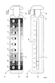
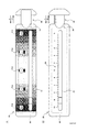
【解決手段】 表面部10は、ストレスのレベルを表す表情画F1〜F9が表示されており、表情画F5がストレスの通常レベルを、表情画F9が最高レベルを、表情画F1が最低レベルを表す。表情画F1〜F9の背景には、表情画F5を中心とした色彩によるグラディエーションが施されている。裏面部20は、表面部10の表情画F1〜F9に対応付けられたストレスのレベル値を示す目盛り24が表示されている。表面部10の表情画F1〜F9を参照して、矢印方向AまたはBにスライダ40を移動させて、主観的に判断したストレスのレベルを表す表情画を赤線422によって指定する。
【選択図】 図1PROBLEM TO BE SOLVED: To provide a tool that can easily convey the level of subjective elements to others.
SOLUTION: On the surface portion 10, facial expression pictures F1 to F9 representing the level of stress are displayed, the facial expression picture F5 has the normal level of stress, the facial expression picture F9 has the highest level, and the facial expression picture F1 has the lowest level. To express. The background of the facial expression paintings F1 to F9 has a color gradient centered on the facial expression painting F5. On the back surface 20, a scale 24 indicating the stress level values associated with the facial expression images F1 to F9 on the front surface 10 is displayed. With reference to the facial expression pictures F1 to F9 on the surface 10, the slider 40 is moved in the arrow direction A or B, and the facial expression picture representing the subjectively determined stress level is designated by the red line 422.
[Selection] Figure 1
Description
この発明は、主観的要素の測定結果を、客観的に表すことを可能とするツールに関するものである。 The present invention relates to a tool that enables objective measurement results of subjective elements to be expressed objectively.
痛みを定量的に測定するため、フェイススケールが用いられている。片桐紀子他「ターミナルケアにおけるFace Scale法を使用した痛みと鎮痛効果の査定」臨床看護、第2巻8号、1996年7月(非特許文献1)には、1人の患者を対象として、痛みのレベルを表情で表したシート(フェイススケール)を使用して、痛みの程度を測定した結果が報告されている。 A face scale is used to measure pain quantitatively. Katakori Noriko et al. “Assessment of Pain and Analgesic Effect Using Face Scale Method in Terminal Care” Clinical Nursing, Vol. 8, No. 8, July 1996 (Non-patent Document 1) The result of measuring the degree of pain using a sheet (face scale) that expresses the level of pain with a facial expression has been reported.
かかる報告は、痛みをレベル化して定量化するという点において注目すべきものである。しかし、多くの患者に対して使用することを目的とするものではなく、痛みのレベルを示す表情を簡易に指定することが困難である。この発明は、このような問題を解決し、主観的要素のレベルを簡易に他人に伝えることができるツールを提供することを目的とする。 Such reports are noteworthy in terms of leveling and quantifying pain. However, it is not intended to be used for many patients, and it is difficult to easily specify a facial expression indicating the level of pain. An object of the present invention is to provide a tool that can solve such a problem and can easily convey the level of subjective elements to others.
(1) この発明のツールは、測定対象である主観的要素を複数のレベルに分け、当該主観的要素のレベルを表現する複数の画像をレベル順に所定の配列方向に表示した画像表示部材と、前記画像表示部材に対し、前記画像の配列方向に相対的にスライド可能に設けられ、位置指定表示を有する位置表示部材とを備えたことを特徴としている。これにより、主観的要素をレベル別に表現した画像を確認しながら、位置表示部材を用いることにより、その画像を容易に指定することができ、主観的要素のレベルを簡易に他人に伝えることができる。 (1) The tool of the present invention divides a subjective element to be measured into a plurality of levels, an image display member displaying a plurality of images expressing the level of the subjective element in a predetermined arrangement direction in order of levels, The image display member includes a position display member that is slidable relative to the image arrangement direction and has a position designation display. Thus, by using the position display member while confirming the image expressing the subjective element for each level, the image can be easily specified, and the level of the subjective element can be easily communicated to others. .
(2) この発明において、前記画像表示部材には、さらに、前記画像に対応付けて、レベル値を示す目盛りが併せて表示されており、前記位置表示部材は、前記画像表示部材に対し、前記目盛りの表示方向に相対的にスライド可能に設けられ、前記目盛り上のレベル値を指定するためのレベル値指定表示を有することを特徴としている。これにより、位置表示部材を用いることにより、主観的要素をレベル別に表現した画像だけでなく、そのレベル値をも容易に指定することができ、主観的要素のレベル値を簡易に他人に伝えることができる。 (2) In the present invention, the image display member further displays a scale indicating a level value in association with the image, and the position display member is It is provided so as to be relatively slidable in the scale display direction, and has a level value designation display for designating a level value on the scale. Thus, by using the position display member, it is possible to easily specify not only the image expressing the subjective elements by level but also the level value, and easily convey the level value of the subjective element to others. Can do.
(3) この発明のツールにおいて、前記位置表示部材の前記位置指定表示が前記画像を指定したときに、前記レベル値指定表示は、当該画像に対応する前記目盛り上のレベル値を指定することを特徴としている。これにより、位置指定表示により画像を指定すれば、指定された画像に対応するレベル値を、レベル値指定表示から容易に取得することができる。 (3) In the tool of the present invention, when the position designation display of the position display member designates the image, the level value designation display designates a level value on the scale corresponding to the image. It is a feature. Thereby, if an image is designated by position designation display, the level value corresponding to the designated image can be easily acquired from the level value designation display.
(4) この発明のツールは、測定対象である主観的要素を、複数のレベルに分け、当該主観的要素のレベルを表現する画像が、レベル順に、各レベルごとに表示され、前記各画像に対応付けて、前記各レベルに応じて、各レベルの順にグラディエーションが施されている主観的要素をレベル付けするためのツールであって、前記画像を指定するための位置表示部材を備えていることを特徴としている。これにより、主観的要素をレベル別に表現した画像だけでなく、各レベルの順に施されたグラディエーションにより、レベルの決定を容易にすることができる。さらに、位置表示部材を用いて画像を指定することにより、主観的要素のレベルを簡易に他人に伝えることができる。 (4) The tool of the present invention divides the subjective elements to be measured into a plurality of levels, and images representing the levels of the subjective elements are displayed for each level in the order of the levels. Correspondingly, it is a tool for leveling subjective elements that are graded in order of each level according to each level, and includes a position display member for designating the image. It is characterized by that. This makes it easy to determine the level not only with images representing subjective elements by level but also with gradients applied in the order of each level. Furthermore, by specifying the image using the position display member, the level of the subjective element can be easily communicated to others.
(5) この発明のツールにおいて、前記各画像の表示位置周辺領域に、前記各レベルに応じて、各レベルの順にグラディエーションが施されていることを特徴している。これにより、各画像およびその表示位置周辺領域に、各レベルの順に施されたグラディエーションにより、レベルの決定を容易にすることができる。 (5) The tool according to the present invention is characterized in that a gradient is applied in the order of each level in accordance with each level in the region around the display position of each image. Thereby, the determination of the level can be facilitated by the gradient applied to each image and its display position peripheral region in the order of each level.
(6) この発明のツールにおいて、さらに、前記画像に対応付けて、レベル値を示す目盛りが併せて表示されていることを特徴としている。これにより、画像によって直接的に示されるレベル値だけでなく、画像と画像との間に対応付けられる中間的なレベル値を、明瞭に認識することができる。 (6) The tool of the present invention is further characterized in that a scale indicating a level value is displayed in association with the image. This makes it possible to clearly recognize not only the level value directly indicated by the image but also the intermediate level value associated between the images.
(7) この発明のツールにおいて、前記各画像は、前記各レベルに応じた顔の表情であることを特徴としている。これにより、レベルごとに異なる顔の表情により、レベルの決定を容易にすることができる。 (7) In the tool according to the present invention, each image is a facial expression corresponding to each level. This makes it easy to determine the level based on facial expressions that differ from level to level.
(8) この発明のツールにおいて、さらに、前記画像に対応付けて、各画像の内容を説明する文言が表記されていることを特徴としている。これにより、画像が示す内容を判断することが困難な場合にでも、文言を参照することによって、画像を選択することができる。 (8) The tool of the present invention is further characterized in that a word describing the contents of each image is written in association with the image. Thereby, even when it is difficult to determine the content indicated by the image, the image can be selected by referring to the wording.
(9) この発明のツールにおいて、前記レベル値を示す目盛りが、前記画像と同時に見えない位置に表示されていることを特徴としている。これにより、使用者にレベル値を顕著に意識させないで選択された画像から、レベル値を取得することができる。 (9) The tool according to the present invention is characterized in that a scale indicating the level value is displayed at a position where it cannot be seen simultaneously with the image. Thereby, the level value can be acquired from the selected image without making the user noticeable the level value.
(10) この発明のツールセットは、測定対象である主観的要素をレベル付けするためのツールを複数種類用意したツールセットであって、前記ツールは、測定対象である主観的要素を、複数のレベルに分け、当該主観的要素のレベルを表現する画像が、レベル順に、各レベルごとに表示されているとともに、当該画像を指定するための位置表示部材を備えており、異なる種類のツールにおいて、表示されたレベルの数が異なっている一方、同一のレベルに対しては同一の画像が用いられていることを特徴としている。これにより、異なる程度のレベル付けにより取得したデータを、統合的に扱う際の客観性を担保することができる。 (10) The tool set of the present invention is a tool set in which a plurality of tools for leveling a subjective element that is a measurement target are prepared, and the tool includes a plurality of subjective elements that are a measurement target. The image representing the level of the subjective element is divided into levels, and is displayed for each level in order of level, and includes a position display member for designating the image. In different types of tools, While the number of displayed levels is different, the same image is used for the same level. Thereby, the objectivity at the time of handling the data acquired by different leveling in an integrated manner can be ensured.
なお、この発明において、「主観的要素」とは、ストレス、不安、痛み、喜び、驚き、悲しみ、爽快感、かゆみ、悪心、不快感、眠気、倦怠感、まぶしさ、苦み等について、医者や患者等が主観的に感じる(判断する)要素のことである。また、自分に対する感覚だけでなく、他人や物に対する印象(不快感、親近感、高級感、質感など)等の要素も含む概念である。 In this invention, “subjective element” means stress, anxiety, pain, joy, surprise, sadness, refreshing feeling, itching, nausea, discomfort, sleepiness, malaise, glare, bitterness, etc. It is an element that a patient or the like feels (judges) subjectively. In addition, it is a concept that includes not only a sense of oneself but also elements such as impressions of other people and things (discomfort, closeness, luxury, texture, etc.).
「画像表示部材」は、下記の実施形態において、表面部10、裏面部20および連結部30に該当する。「位置表示部材」は、下記の実施形態において、スライダー40に該当する。「位置指定表示」は、下記の実施形態において、赤線422に該当する。「レベル値指定表示」は、下記の実施形態において、赤線424に該当する。なお、位置指定表示とレベル値指定表示は同一のものであってもよい。
The “image display member” corresponds to the
「画像の配列方向に相対的にスライダ可能」とは、下記の実施形態に示すように、直線方向にスライドする場合に限らず(図1の矢印方向A、B)、図7に示すように、回転方向してスライドする場合(図7の矢印方向530)等も含む概念である。
“Slidable relative to the image arrangement direction” is not limited to the case of sliding in the linear direction (arrow directions A and B in FIG. 1), as shown in the following embodiment, as shown in FIG. This is a concept including the case of sliding in the rotation direction (
10・・・・表面部
20・・・・裏面部
24・・・・ストレスのレベル値を示す目盛り
30・・・・連結部
40・・・・スライダ
F1〜F9・・・・表情画
10 ・ ・ ・ ・ Surface
20 ・ ・ ・ ・ Back side
24 .... Scale indicating the stress level
30 ... Connection part
40 .... Slider
F1 ~ F9 ...
図1Aに一実施形態における「主観的要素をレベル付けするためのツール(以下、スマイルスケールとする)」の平面図を、図1Bに底面図を示す。スマイルスケールは、プラスチック素材で形成された表面部10、裏面部20、連結部30(点線部分)およびスライダ40を備えている。表面部10および裏面部20は、それぞれ一定の厚さを有しており、それらの前側面側、左側面側および後側面側に設けられた連結部30(点線部分)を介してつながっている。図2A、図2Bに、それぞれ表面部10側、前側面側から見たときの連結部30を示す。連結部30は、図1Aおよび図1Bの点線に示すような形状をしており、一定の厚さを有している。また、前後方向にて連結部30に挟まれているスライダ40は、表面部10および裏面部20間を、表面部10および裏面部20に接しながら左右方向(矢印方向A、B)に移動可能である。
FIG. 1A shows a plan view of a “tool for leveling subjective elements (hereinafter referred to as smile scale)” in one embodiment, and FIG. 1B shows a bottom view. The smile scale includes a
表面部10は、図1Aに示すように、各角部を丸くした長方形をなしており、ストレスのレベルを9段階に分け、各レベルを表す表情画F1〜F9が表示されている。これらは、まゆげ、目、口の形状、汗の有無および顔色を組み合わせることによって、ストレスのレベルを表情として表現するようにしている。表情画F5がストレスの通常レベルを、表情画F9がストレスの最高レベルを、表情画F1がストレスの最低レベルを表す。さらに、表情画F1〜F9の背景には、表情画F5を中心としたグラディエーションが施されている。表情画F5から左側には、緑色が徐々に濃くなるようなグラディエーションが施され、表情画F5から右側には、ピンク色が徐々に濃くなるようなグラディエーションが施されている。
As shown in FIG. 1A, the
さらに、表情画F1〜F9の表示方向に並行に長穴12が設けられており、表面方向からスライダ40の一部分を見ることができるようになっている。また、表面部10の右辺中央部には、半円状のくり貫き14が設けられており、スライダ40を指でつかみ易くしている。
Further, a
裏面部20は、図1Bに示すように、各角部を丸くした長方形をなしており、表面部10に設けられた長穴12と同一形状・大きさの長穴22が中央に設けられている。この長穴22に並行して、表面部10の表情画F1〜F9に対応付けられたストレスのレベル値を示す目盛り24が表示されている。表情画F1はストレス値0に対応し、表情画F9はストレス値10に対応している。また、右辺中央部には、表面部10に設けられたものと同一形状・大きさの半円状のくり貫き26が設けられている。
As shown in FIG. 1B, the
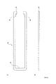
図3A、図3B、図3Cに、それぞれ表面部10側、前側面側、裏面部20側から見たときのスライダ40を示す。本体420は、表情画を指定するための赤線422および赤線424が対応付けて両面に記されており、左側は各角部を丸くした長方形状をなした左ロック部426を備えている。本体420底面の右側には、各角部を丸くした台形状の右ロック部440を備えている。本体420の赤線422、424の一部分は、表面部10および裏面部20に設けられた長穴12、22を介して、その位置を確認することができる。
3A, 3B, and 3C show the
左ロック部426は、表面部10および裏面部20間を移動し、スライダ40が図1Aに示す矢印方向Aに最大限移動したときに、図2Aに示す連結部30の当接部32に当接するものである。また、左ロック部426は、スライダ40が図1Aに示す矢印方向Bに最大限移動したときに、図2Aに示す連結部30の当接部34、36に当接することによって、表面部10および裏面部20間からスライダ40が分離することがないようにする。右ロック部440は、スライダ40が図1Aに示す矢印方向Aに最大限移動したときに、図2Aに示す連結部30の当接部38に当接するものである。なお、スライダ40が図1Aに示す矢印方向Aに最大限移動したときに、赤線422が表面部10の表情画F9を指定するような位置(赤線424が裏面部20のストレス値10を指定するような位置)に、赤線422、424が記されている。また、本体420と右ロック部440の連結部分の厚さは、連結部30の厚さとほぼ同じである。また、本体420の裏面側には、目盛り428が記されている。
The
例えば、患者がスマイルスケールを使用する場合、スライダ40を指でつかみ、図1Aに示す表面部10の表情画F1〜F9を参照して、図1Aに示す矢印方向AまたはBにスライダ40を移動させて、主観的に判断したストレスのレベルを表す表情画を赤線422によって指定する。この実施形態では、患者は、普段より少しストレスを感じていると判断して、表面部10の表情画F6を指定し、スマイルスケールを医者に示す(図4参照)。これにより、医者は、赤線422により指定された表情画F6(または赤線424により指定された裏面部20のストレス値約6.2〜6.3)を参照して、患者自身が感じているストレス状態を把握することができる。なお、医者が、診察結果であるストレス状態を患者に示すために、スマイルスケールを用いてもよい。これにより、患者は、医者によって指定された表情画を参照することによって、自身のストレス状態を把握することができる。
For example, when the patient uses a smile scale, grasp the
なお、上記の実施形態では、表情画F1〜F9の背景には、色彩のグラディエーションが施されている。しかしながら、模様のグラディエーションであってもよい。また、表情画の背景にグラディエーションを施さなくてもよい。 In the above-described embodiment, color gradient is applied to the background of the facial expression images F1 to F9. However, it may be a pattern gradient. Moreover, it is not necessary to perform gradation on the background of the facial expression.
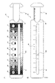
また、上記の実施形態では、表情画を9段階で表示しているが、他の段階数で表示してもよい。また、9段階と5段階というように、異なる段階数のスマイルスケールを併用してもよい。この5段階で表情画を表示したスマイルスケールの表面部10の一例を、図5に示す。図1Aおよび図5に示すように、段階数は異なるものの、各レベルにおける表情画を同一のものとしておくことが好ましい(F11とF1、F12とF3、F13とF5、F14とF7、F15とF9がそれぞれ対応)。また、レベル数も同一のものを付しておくことが好ましい。このようにすれば、諸事情によって、統一した段階数を用いることができない場合であっても、取得したデータの統一性を維持することが可能である。
Further, in the above embodiment, the facial expression image is displayed in nine stages, but may be displayed in other stages. Also, smile scales with different numbers of stages such as 9 stages and 5 stages may be used in combination. FIG. 5 shows an example of the smile
また、上記の実施形態では、使用者にレベル値を顕著に意識させないために、ストレス値を示す目盛りを、表情画が表示された表面部10からは見えない位置(裏面部20)に表示している。しかしながら、ストレス値を示す目盛りを、表情画と同時に見える位置(表面部10)に表示してもよい。
In the above embodiment, the scale indicating the stress value is displayed at a position (back surface portion 20) that cannot be seen from the
また、上記の実施形態では、ストレスについてのレベル化を行ったが、不安、喜び、驚き等についても適用することができる。また、顔の表情によってレベルを表現したが、風景、模様など、人間の感情を直接的間接的に表現したものを用いることができる。また、ストレスのレベルを表現した画像(顔の表情、風景、模様等)を説明する文言を、各画像に付記してもよい。この場合の表面部10の一例を、図6に示す。このようにすれば、画像が示す内容を判断することが困難な場合にでも、文言を参照することによって、画像を指定することができる。なお、画像を説明する文言を、各画像に対応付けて裏面部20に表記してもよい。
In the above embodiment, the level of stress is leveled, but it can also be applied to anxiety, joy, surprise, and the like. In addition, although the level is expressed by facial expressions, it is possible to use a direct or indirect expression of human emotions such as landscapes and patterns. Further, a word describing an image expressing a stress level (facial expression, landscape, pattern, etc.) may be added to each image. An example of the
また、上記の実施形態では、スライダ40が図1Aに示す矢印方向Aに最大限移動したときに、右ロック部440が図2Aに示す連結部30の当接部38に当接するようスライダ40を構成している。しかしながら、右ロック部440が裏面部20の右側面に当接するように、スライダ40を構成してもよい。
Further, in the above embodiment, when the
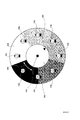
また、上記の実施形態では、複数の表情画を一列に表示している。しかしながら、これに限られるものではなく、複数列に表示したり、円上または半円上に表示したりしてもよい。図7に、表情画を円上に表示したときのツールの一例を示す。これは、円状の厚紙である下円盤500と、それとピン510で連結され、円状の厚紙である上円盤520から構成される。上円盤520は、下円盤500上を矢印方向530に回転可能であり、位置指定表示である矢印522により、下円盤500上に表示されている表情画F21〜F28を指定することができる。また、下円盤500の裏面に、ストレスのレベル値を、表情画F21〜F28に対応付けて円上に記しておくとよい。なお、画像表示部材が下円盤500に、位置表示部材が上円盤520に該当する。
In the above embodiment, a plurality of facial expression images are displayed in a line. However, the present invention is not limited to this, and may be displayed in a plurality of columns, or may be displayed on a circle or a semicircle. FIG. 7 shows an example of a tool when a facial expression image is displayed on a circle. This is composed of a
また、上記の実施形態におけるスマイルスケールのスライダ40の構成は一例であって、これに限られるものではない。例えば、表情画F1〜F9の表示方向に並行して設けられたスライダ軸と、その軸上を移動可能な指定部材を設けてスライダ40を構成してもよい。
In addition, the configuration of the
Claims (10)
前記画像表示部材に対し、前記画像の配列方向に相対的にスライド可能に設けられ、位置指定表示を有する位置表示部材と、
を備えたことを特徴とするツール。 An image display member that divides a subjective element to be measured into a plurality of levels, and displays a plurality of images representing the level of the subjective element in a predetermined arrangement direction in order of levels
A position display member that is provided so as to be slidable relative to the image display member in the arrangement direction of the images, and that has a position designation display;
A tool characterized by having
前記画像表示部材には、さらに、前記画像に対応付けて、レベル値を示す目盛りが併せて表示されており、
前記位置表示部材は、前記画像表示部材に対し、前記目盛りの表示方向に相対的にスライド可能に設けられ、前記目盛り上のレベル値を指定するためのレベル値指定表示を有することを特徴とするもの。 The tool of claim 1,
The image display member further displays a scale indicating a level value in association with the image,
The position display member is provided to be slidable relative to the image display member in the scale display direction, and has a level value designation display for designating a level value on the scale. thing.
前記各画像に対応付けて、前記各レベルに応じて、各レベルの順にグラディエーションが施されている主観的要素をレベル付けするためのツールであって、
前記画像を指定するための位置表示部材を備えていることを特徴とするツール。 The subjective element that is the measurement target is divided into a plurality of levels, and an image representing the level of the subjective element is displayed for each level in order of level.
A tool for leveling subjective elements that are graded in order of each level according to each level in association with each image,
A tool comprising a position display member for designating the image.
前記ツールは、測定対象である主観的要素を、複数のレベルに分け、当該主観的要素のレベルを表現する画像が、レベル順に、各レベルごとに表示されているとともに、当該画像を指定するための位置表示部材を備えており、
異なる種類のツールにおいて、表示されたレベルの数が異なっている一方、同一のレベルに対しては同一の画像が用いられていることを特徴とするツールセット。 A tool set with multiple tools for leveling the subjective elements being measured,
The tool divides a subjective element to be measured into a plurality of levels, and an image representing the level of the subjective element is displayed for each level in order of level, and the image is designated. The position display member of
A tool set, wherein different types of tools have different numbers of displayed levels, but the same image is used for the same level.
Priority Applications (1)
| Application Number | Priority Date | Filing Date | Title |
|---|---|---|---|
| JP2010048760A JP2010179110A (en) | 2010-03-05 | 2010-03-05 | Tool for providing subjective element with level |
Applications Claiming Priority (1)
| Application Number | Priority Date | Filing Date | Title |
|---|---|---|---|
| JP2010048760A JP2010179110A (en) | 2010-03-05 | 2010-03-05 | Tool for providing subjective element with level |
Related Parent Applications (1)
| Application Number | Title | Priority Date | Filing Date |
|---|---|---|---|
| JP2001366107A Division JP4512300B2 (en) | 2001-11-30 | 2001-11-30 | Tools for leveling subjective elements |
Publications (1)
| Publication Number | Publication Date |
|---|---|
| JP2010179110A true JP2010179110A (en) | 2010-08-19 |
Family
ID=42761095
Family Applications (1)
| Application Number | Title | Priority Date | Filing Date |
|---|---|---|---|
| JP2010048760A Pending JP2010179110A (en) | 2010-03-05 | 2010-03-05 | Tool for providing subjective element with level |
Country Status (1)
| Country | Link |
|---|---|
| JP (1) | JP2010179110A (en) |
Citations (7)
| Publication number | Priority date | Publication date | Assignee | Title |
|---|---|---|---|---|
| JPS5646844U (en) * | 1979-09-20 | 1981-04-25 | ||
| JPS5834025U (en) * | 1981-08-31 | 1983-03-05 | 安藤 和明 | Label with thermometer for easy identification of scale |
| US4844091A (en) * | 1988-01-26 | 1989-07-04 | C.P.S. Inc. | Method for monitoring a state of being |
| JPH09215670A (en) * | 1996-02-07 | 1997-08-19 | Noriyasu Sakamoto | Digital type radiation inspecting instrument |
| US6258042B1 (en) * | 1999-09-17 | 2001-07-10 | James S. Factor | Visual analog scale and method of use for the diagnosis and/or treatment of physical pain |
| JP2001314183A (en) * | 2000-02-29 | 2001-11-13 | Japan Science & Technology Corp | Lymphocytes with enhanced killer activity |
| JP2003091591A (en) * | 2001-09-19 | 2003-03-28 | Sumitomo Pharmaceut Co Ltd | Tools and systems for leveling subjective factors |
-
2010
- 2010-03-05 JP JP2010048760A patent/JP2010179110A/en active Pending
Patent Citations (7)
| Publication number | Priority date | Publication date | Assignee | Title |
|---|---|---|---|---|
| JPS5646844U (en) * | 1979-09-20 | 1981-04-25 | ||
| JPS5834025U (en) * | 1981-08-31 | 1983-03-05 | 安藤 和明 | Label with thermometer for easy identification of scale |
| US4844091A (en) * | 1988-01-26 | 1989-07-04 | C.P.S. Inc. | Method for monitoring a state of being |
| JPH09215670A (en) * | 1996-02-07 | 1997-08-19 | Noriyasu Sakamoto | Digital type radiation inspecting instrument |
| US6258042B1 (en) * | 1999-09-17 | 2001-07-10 | James S. Factor | Visual analog scale and method of use for the diagnosis and/or treatment of physical pain |
| JP2001314183A (en) * | 2000-02-29 | 2001-11-13 | Japan Science & Technology Corp | Lymphocytes with enhanced killer activity |
| JP2003091591A (en) * | 2001-09-19 | 2003-03-28 | Sumitomo Pharmaceut Co Ltd | Tools and systems for leveling subjective factors |
Similar Documents
| Publication | Publication Date | Title |
|---|---|---|
| Fortin et al. | Wayfinding in the blind: larger hippocampal volume and supranormal spatial navigation | |
| JP3656256B2 (en) | Computer judgment display system for obesity and skinny | |
| Banks et al. | Test-retest reliability and agreement between in-person and video assessment of facial mimetic function using the eFACE facial grading system | |
| Watson et al. | Quaddles: A multidimensional 3-D object set with parametrically controlled and customizable features | |
| CN105190706B (en) | 3D patient interface devices select system and method | |
| Grad et al. | Application of HoloLens‐based augmented reality and three‐dimensional printed anatomical tooth reference models in dental education | |
| JP5996144B1 (en) | Coloring Color Psychological Diagnosis System, Coloring Color Psychological Diagnosis Method, and Coloring Color Psychological Diagnosis Program | |
| CN107361843B (en) | Immersive neurosurgery simulation method with real touch | |
| Imai et al. | Facial cues to age perception using three-dimensional analysis | |
| Babu et al. | Occlusion indicators: A review | |
| Tanikawa et al. | Functional decline in facial expression generation in older women: a cross-sectional study using three-dimensional morphometry | |
| Fink et al. | The effect of incobotulinumtoxin a and dermal filler treatment on perception of age, health, and attractiveness of female faces | |
| US20240148315A1 (en) | Xr-based platform for neuro-cognitive-motor-affective assessments | |
| JP4512300B2 (en) | Tools for leveling subjective elements | |
| Hayes et al. | What’s wrong with this picture? An experiment in quantifying accuracy in 2D portrait drawing | |
| US7787676B2 (en) | Method for integration of vectorial and/or tensorial measurement data into a representation of an anatomical image exposure | |
| JP2010179110A (en) | Tool for providing subjective element with level | |
| Dsouza et al. | Development of a smartphone-based skin simulation model for medical education | |
| Luo et al. | Enhancing dental education: integrating online learning in complete denture rehabilitation | |
| He et al. | The impact of motor imageries on aesthetic judgment of Chinese calligraphy: An fMRI Study | |
| Kapoula et al. | Motion and lateral organization in monet’s painting impact body sway? | |
| Fukuda et al. | A new method to evaluate lower eyelid sag using three‐dimensional image analysis | |
| TWI699669B (en) | Mixed reality action function evaluation system | |
| CN214965450U (en) | Pain scoring tool | |
| Habacha | The role of motor processes in mental rotation: Selective shaping of cognitive processing via specific sensorimotor experience |
Legal Events
| Date | Code | Title | Description |
|---|---|---|---|
| A521 | Written amendment |
Free format text: JAPANESE INTERMEDIATE CODE: A523 Effective date: 20100518 |
|
| A131 | Notification of reasons for refusal |
Free format text: JAPANESE INTERMEDIATE CODE: A131 Effective date: 20120521 |
|
| A02 | Decision of refusal |
Free format text: JAPANESE INTERMEDIATE CODE: A02 Effective date: 20120813 |