JP2010164949A - Method for processing data, apparatus for performing the method, and display apparatus having the driving apparatus - Google Patents
Method for processing data, apparatus for performing the method, and display apparatus having the driving apparatus Download PDFInfo
- Publication number
- JP2010164949A JP2010164949A JP2009249379A JP2009249379A JP2010164949A JP 2010164949 A JP2010164949 A JP 2010164949A JP 2009249379 A JP2009249379 A JP 2009249379A JP 2009249379 A JP2009249379 A JP 2009249379A JP 2010164949 A JP2010164949 A JP 2010164949A
- Authority
- JP
- Japan
- Prior art keywords
- data
- frame data
- mode
- automatic rotation
- unit
- Prior art date
- Legal status (The legal status is an assumption and is not a legal conclusion. Google has not performed a legal analysis and makes no representation as to the accuracy of the status listed.)
- Pending
Links
- 238000000034 method Methods 0.000 title claims abstract description 15
- 238000003672 processing method Methods 0.000 claims description 19
- 230000008569 process Effects 0.000 claims description 5
- 238000010586 diagram Methods 0.000 description 19
- 239000004973 liquid crystal related substance Substances 0.000 description 14
- 239000011159 matrix material Substances 0.000 description 3
- 230000004044 response Effects 0.000 description 3
- 239000003086 colorant Substances 0.000 description 2
- 230000006870 function Effects 0.000 description 2
- 238000004519 manufacturing process Methods 0.000 description 2
- 238000012986 modification Methods 0.000 description 2
- 230000004048 modification Effects 0.000 description 2
- 230000008859 change Effects 0.000 description 1
- 239000012528 membrane Substances 0.000 description 1
- 230000001360 synchronised effect Effects 0.000 description 1
- 238000004148 unit process Methods 0.000 description 1
Images


Classifications
-
- G—PHYSICS
- G09—EDUCATION; CRYPTOGRAPHY; DISPLAY; ADVERTISING; SEALS
- G09G—ARRANGEMENTS OR CIRCUITS FOR CONTROL OF INDICATING DEVICES USING STATIC MEANS TO PRESENT VARIABLE INFORMATION
- G09G5/00—Control arrangements or circuits for visual indicators common to cathode-ray tube indicators and other visual indicators
- G09G5/003—Details of a display terminal, the details relating to the control arrangement of the display terminal and to the interfaces thereto
- G09G5/005—Adapting incoming signals to the display format of the display terminal
-
- G—PHYSICS
- G09—EDUCATION; CRYPTOGRAPHY; DISPLAY; ADVERTISING; SEALS
- G09G—ARRANGEMENTS OR CIRCUITS FOR CONTROL OF INDICATING DEVICES USING STATIC MEANS TO PRESENT VARIABLE INFORMATION
- G09G3/00—Control arrangements or circuits, of interest only in connection with visual indicators other than cathode-ray tubes
- G09G3/20—Control arrangements or circuits, of interest only in connection with visual indicators other than cathode-ray tubes for presentation of an assembly of a number of characters, e.g. a page, by composing the assembly by combination of individual elements arranged in a matrix no fixed position being assigned to or needed to be assigned to the individual characters or partial characters
- G09G3/34—Control arrangements or circuits, of interest only in connection with visual indicators other than cathode-ray tubes for presentation of an assembly of a number of characters, e.g. a page, by composing the assembly by combination of individual elements arranged in a matrix no fixed position being assigned to or needed to be assigned to the individual characters or partial characters by control of light from an independent source
- G09G3/36—Control arrangements or circuits, of interest only in connection with visual indicators other than cathode-ray tubes for presentation of an assembly of a number of characters, e.g. a page, by composing the assembly by combination of individual elements arranged in a matrix no fixed position being assigned to or needed to be assigned to the individual characters or partial characters by control of light from an independent source using liquid crystals
- G09G3/3611—Control of matrices with row and column drivers
- G09G3/3648—Control of matrices with row and column drivers using an active matrix
- G09G3/3659—Control of matrices with row and column drivers using an active matrix the addressing of the pixel involving the control of two or more scan electrodes or two or more data electrodes, e.g. pixel voltage dependant on signal of two data electrodes
-
- G—PHYSICS
- G09—EDUCATION; CRYPTOGRAPHY; DISPLAY; ADVERTISING; SEALS
- G09G—ARRANGEMENTS OR CIRCUITS FOR CONTROL OF INDICATING DEVICES USING STATIC MEANS TO PRESENT VARIABLE INFORMATION
- G09G2300/00—Aspects of the constitution of display devices
- G09G2300/04—Structural and physical details of display devices
- G09G2300/0404—Matrix technologies
- G09G2300/0408—Integration of the drivers onto the display substrate
-
- G—PHYSICS
- G09—EDUCATION; CRYPTOGRAPHY; DISPLAY; ADVERTISING; SEALS
- G09G—ARRANGEMENTS OR CIRCUITS FOR CONTROL OF INDICATING DEVICES USING STATIC MEANS TO PRESENT VARIABLE INFORMATION
- G09G2300/00—Aspects of the constitution of display devices
- G09G2300/04—Structural and physical details of display devices
- G09G2300/0421—Structural details of the set of electrodes
- G09G2300/0426—Layout of electrodes and connections
-
- G—PHYSICS
- G09—EDUCATION; CRYPTOGRAPHY; DISPLAY; ADVERTISING; SEALS
- G09G—ARRANGEMENTS OR CIRCUITS FOR CONTROL OF INDICATING DEVICES USING STATIC MEANS TO PRESENT VARIABLE INFORMATION
- G09G2310/00—Command of the display device
- G09G2310/02—Addressing, scanning or driving the display screen or processing steps related thereto
- G09G2310/0264—Details of driving circuits
- G09G2310/0281—Arrangement of scan or data electrode driver circuits at the periphery of a panel not inherent to a split matrix structure
-
- G—PHYSICS
- G09—EDUCATION; CRYPTOGRAPHY; DISPLAY; ADVERTISING; SEALS
- G09G—ARRANGEMENTS OR CIRCUITS FOR CONTROL OF INDICATING DEVICES USING STATIC MEANS TO PRESENT VARIABLE INFORMATION
- G09G2310/00—Command of the display device
- G09G2310/02—Addressing, scanning or driving the display screen or processing steps related thereto
- G09G2310/0264—Details of driving circuits
- G09G2310/0283—Arrangement of drivers for different directions of scanning
-
- G—PHYSICS
- G09—EDUCATION; CRYPTOGRAPHY; DISPLAY; ADVERTISING; SEALS
- G09G—ARRANGEMENTS OR CIRCUITS FOR CONTROL OF INDICATING DEVICES USING STATIC MEANS TO PRESENT VARIABLE INFORMATION
- G09G2340/00—Aspects of display data processing
- G09G2340/02—Handling of images in compressed format, e.g. JPEG, MPEG
-
- G—PHYSICS
- G09—EDUCATION; CRYPTOGRAPHY; DISPLAY; ADVERTISING; SEALS
- G09G—ARRANGEMENTS OR CIRCUITS FOR CONTROL OF INDICATING DEVICES USING STATIC MEANS TO PRESENT VARIABLE INFORMATION
- G09G2340/00—Aspects of display data processing
- G09G2340/04—Changes in size, position or resolution of an image
- G09G2340/0492—Change of orientation of the displayed image, e.g. upside-down, mirrored
-
- G—PHYSICS
- G09—EDUCATION; CRYPTOGRAPHY; DISPLAY; ADVERTISING; SEALS
- G09G—ARRANGEMENTS OR CIRCUITS FOR CONTROL OF INDICATING DEVICES USING STATIC MEANS TO PRESENT VARIABLE INFORMATION
- G09G2340/00—Aspects of display data processing
- G09G2340/16—Determination of a pixel data signal depending on the signal applied in the previous frame
-
- G—PHYSICS
- G09—EDUCATION; CRYPTOGRAPHY; DISPLAY; ADVERTISING; SEALS
- G09G—ARRANGEMENTS OR CIRCUITS FOR CONTROL OF INDICATING DEVICES USING STATIC MEANS TO PRESENT VARIABLE INFORMATION
- G09G2360/00—Aspects of the architecture of display systems
- G09G2360/18—Use of a frame buffer in a display terminal, inclusive of the display panel
-
- G—PHYSICS
- G09—EDUCATION; CRYPTOGRAPHY; DISPLAY; ADVERTISING; SEALS
- G09G—ARRANGEMENTS OR CIRCUITS FOR CONTROL OF INDICATING DEVICES USING STATIC MEANS TO PRESENT VARIABLE INFORMATION
- G09G2370/00—Aspects of data communication
- G09G2370/08—Details of image data interface between the display device controller and the data line driver circuit
-
- G—PHYSICS
- G09—EDUCATION; CRYPTOGRAPHY; DISPLAY; ADVERTISING; SEALS
- G09G—ARRANGEMENTS OR CIRCUITS FOR CONTROL OF INDICATING DEVICES USING STATIC MEANS TO PRESENT VARIABLE INFORMATION
- G09G3/00—Control arrangements or circuits, of interest only in connection with visual indicators other than cathode-ray tubes
- G09G3/20—Control arrangements or circuits, of interest only in connection with visual indicators other than cathode-ray tubes for presentation of an assembly of a number of characters, e.g. a page, by composing the assembly by combination of individual elements arranged in a matrix no fixed position being assigned to or needed to be assigned to the individual characters or partial characters
- G09G3/34—Control arrangements or circuits, of interest only in connection with visual indicators other than cathode-ray tubes for presentation of an assembly of a number of characters, e.g. a page, by composing the assembly by combination of individual elements arranged in a matrix no fixed position being assigned to or needed to be assigned to the individual characters or partial characters by control of light from an independent source
- G09G3/36—Control arrangements or circuits, of interest only in connection with visual indicators other than cathode-ray tubes for presentation of an assembly of a number of characters, e.g. a page, by composing the assembly by combination of individual elements arranged in a matrix no fixed position being assigned to or needed to be assigned to the individual characters or partial characters by control of light from an independent source using liquid crystals
- G09G3/3611—Control of matrices with row and column drivers
- G09G3/3648—Control of matrices with row and column drivers using an active matrix
Landscapes
- Engineering & Computer Science (AREA)
- Physics & Mathematics (AREA)
- Computer Hardware Design (AREA)
- General Physics & Mathematics (AREA)
- Theoretical Computer Science (AREA)
- Chemical & Material Sciences (AREA)
- Crystallography & Structural Chemistry (AREA)
- Control Of Indicators Other Than Cathode Ray Tubes (AREA)
- Liquid Crystal Display Device Control (AREA)
- Liquid Crystal (AREA)
- Transforming Electric Information Into Light Information (AREA)
Abstract
Description
本発明は、データ処理方法、これを実行するための装置、及びこの装置を含む表示装置に関し、より詳しくは表示品質を向上させるためのデータ処理方法、これを実行するための装置、及びこの装置を含む表示装置に関する。 The present invention relates to a data processing method, an apparatus for executing the same, and a display device including the apparatus, and more particularly, a data processing method for improving display quality, an apparatus for executing the data, and the apparatus. The present invention relates to a display device including:
一般的に、液晶表示装置は、液晶表示パネルと、液晶表示パネルを駆動させる駆動チップが取り付けられた印刷回路基板と、液晶表示パネルと印刷回路基板とを電気的に接続し、ソース駆動チップが取り付けられたソーステープキャリアパッケージ及びゲート駆動チップが取り付けられたゲートテープキャリアパッケージと、を含む。一般的に、液晶表示装置は、マトリックス形状に配列された単位画素を含む。縦方向に延びたデータラインはデータ信号を単位画素に提供し、横方向に延びたゲートラインは、単位画素をスキャンする。 Generally, a liquid crystal display device electrically connects a liquid crystal display panel, a printed circuit board to which a driving chip for driving the liquid crystal display panel is attached, a liquid crystal display panel and the printed circuit board, and a source driving chip is provided. And an attached source tape carrier package and a gate tape carrier package to which a gate driving chip is attached. Generally, a liquid crystal display device includes unit pixels arranged in a matrix shape. The data line extending in the vertical direction provides a data signal to the unit pixel, and the gate line extending in the horizontal direction scans the unit pixel.
装置のサイズを小さくし、製造原価を節減するために、ゲートテープキャリアパッケージを除去し、ゲート駆動回路を液晶表示パネルに直接形成するGIL(Gate IC Less)構造が開発されて液晶表示装置に適用されている。 In order to reduce the size of the device and reduce manufacturing costs, a GIL (Gate IC Less) structure was developed in which the gate tape carrier package was removed and the gate drive circuit was formed directly on the liquid crystal display panel, and applied to the liquid crystal display device. Has been.
これとともに、ソース駆動チップの個数を減らすために、色を表し、単位画素に含まれているサブ画素の長辺が液晶表示パネルの上側に配列された、即ち、横画素構造が採用されている。横画素構造において、レッドカラー画素、グリーンカラー画素、及びブルーカラー画素の各々は、ゲートラインの延長方向である横方向に沿ってその長辺が配置され、データラインの延長方向である縦方向に沿ってその短辺が配置されて、レッド、グリーン、及びブルー画素が縦方向に配列される構造である。GIL構造及び横画素構造を取り入れることによって液晶表示装置の部品数及び製造費用が節約できる。 At the same time, in order to reduce the number of source driving chips, a color pixel is displayed, and the long sides of the sub-pixels included in the unit pixel are arranged on the upper side of the liquid crystal display panel, that is, a horizontal pixel structure is adopted. . In the horizontal pixel structure, each of the red color pixel, the green color pixel, and the blue color pixel has a long side arranged along a horizontal direction that is an extension direction of the gate line, and extends in a vertical direction that is an extension direction of the data line. The short side is arranged along the red and green and blue pixels are arranged in the vertical direction. By adopting the GIL structure and the horizontal pixel structure, the number of parts and the manufacturing cost of the liquid crystal display device can be saved.
しかし、横画素構造を採用する液晶表示装置では、各々の色画素の長辺及び短辺、即ち、色画素の長さ及び幅の大きさが、横画素構造を採用しない一般的な液晶表示装置と反対であるため、横画素構造を取り入れる液晶表示装置の出力イメージは歪曲される場合がある。 However, in a liquid crystal display device adopting a horizontal pixel structure, a general liquid crystal display device in which the long side and the short side of each color pixel, that is, the length and width of the color pixel do not adopt the horizontal pixel structure. Therefore, the output image of the liquid crystal display device incorporating the horizontal pixel structure may be distorted.
本発明の技術的課題は、上述のような点を解決するためのものであり、本発明の目的は、観察者を基準にして、出力画像が常に正常方向にディスプレイされるようにすることによって、表示品質を向上させることのできるデータ処理方法を提供することにある。 The technical problem of the present invention is to solve the above-described points, and the object of the present invention is to always display an output image in a normal direction with respect to an observer. Another object of the present invention is to provide a data processing method capable of improving display quality.
本発明の他の目的は、前記データ処理方法を実行するためのデータ処理装置を提供することにある。 Another object of the present invention is to provide a data processing apparatus for executing the data processing method.
本発明のさらに他の目的は、前記データ処理装置を備えた表示装置を提供することにある。 Still another object of the present invention is to provide a display device including the data processing device.
上述の本発明の目的を達成するために、本発明の一実施形態によるデータ処理方法は、p番目フレームデータ(ここで、pは自然数)を保存し、p番目フレームデータに対応するデータイネーブル信号のパルス数に基づいてp番目フレームデータの表示モードが非自動回転モードであるか自動回転モードであるかを判断し、判断された表示モードに応じてp番目フレームデータを処理すること、を含む。 In order to achieve the above-described object of the present invention, a data processing method according to an embodiment of the present invention stores p-th frame data (where p is a natural number) and a data enable signal corresponding to the p-th frame data. Determining whether the display mode of the p-th frame data is the non-automatic rotation mode or the automatic rotation mode based on the number of pulses, and processing the p-th frame data according to the determined display mode. .
本発明の実施形態において、決定された表示モードが、非自動回転モード(non-self-pivotable display mode)である場合、保存されたp番目フレームデータを回転させてもよい。 In the embodiment of the present invention, when the determined display mode is a non-self-pivotable display mode, the stored p-th frame data may be rotated.
本発明の実施形態において、p番目フレームデータの判断された表示モードが自動回転モード(self-pivotable display mode)である場合、(p+1)番目フレームデータを保存されたp番目フレームデータを利用して補償してもよい。 In the embodiment of the present invention, when the determined display mode of the p-th frame data is the self-pivotable display mode, the (p + 1) th frame data is used to store the p-th frame data. You may compensate.
本発明の実施形態において、(p+1)番目フレームデータの補償は、保存されたp番目フレームデータの回転無しに実行されてもよい。 In the embodiment of the present invention, the compensation of the (p + 1) th frame data may be performed without rotating the stored pth frame data.
本発明の実施形態において、非自動回転モードの場合、p番目フレームデータに対応するデータイネーブル信号のパルス数が自動回転モードの場合よりも少なく、自動回転モードの場合、p番目フレームデータに対応するデータイネーブル信号のパルス数が前記非自動回転モードの場合よりも多くてもよい。 In the embodiment of the present invention, in the non-automatic rotation mode, the number of pulses of the data enable signal corresponding to the p-th frame data is smaller than in the automatic rotation mode, and in the automatic rotation mode, it corresponds to the p-th frame data. The number of pulses of the data enable signal may be larger than that in the non-automatic rotation mode.
本発明の実施形態において、非自動回転モードは、ベーシック入/出力システムモードであってもよく、自動回転モードは、ウィンドウズモードであってもよい。 In an embodiment of the present invention, the non-automatic rotation mode may be a basic input / output system mode, and the automatic rotation mode may be a Windows mode.
本発明の実施形態において、p番目フレームデータを保存する前にp番目フレームデータを圧縮エンコードしてもよく、p番目フレームデータを処理する前に、圧縮エンコードされたp番目フレームデータを圧縮デコードしてもよい。 In the embodiment of the present invention, the p-th frame data may be compression-encoded before storing the p-th frame data, and the compression-encoded p-th frame data is compressed and decoded before the p-th frame data is processed. May be.
上述の本発明の他の目的を達成するために、本発明の一実施形態によるデータ処理装置は、保存部、モード判断部、及びデータ処理部を含む。保存部は、p番目フレームデータ(ここで、pは自然数)を保存する。モード判断部は、p番目フレームデータに対応するデータイネーブル信号のパルス数に基づいてp番目フレームデータの表示モードが非自動回転モードであるか自動回転モードであるかを判断する。データ処理部は、判断された表示モードに応じて表示パネルに対応するようp番目フレームデータを処理する。 In order to achieve another object of the present invention, a data processing apparatus according to an embodiment of the present invention includes a storage unit, a mode determination unit, and a data processing unit. The storage unit stores p-th frame data (where p is a natural number). The mode determination unit determines whether the display mode of the pth frame data is the non-automatic rotation mode or the automatic rotation mode based on the number of pulses of the data enable signal corresponding to the pth frame data. The data processing unit processes the p-th frame data so as to correspond to the display panel according to the determined display mode.
本発明の実施形態において、データ処理装置は、p番目フレームデータを圧縮エンコードして保存部に提供するエンコーダー及び圧縮エンコードされたp番目フレームデータをデコードしてデータ処理部に提供するデコーダーをさらに含んでもよい。 In an embodiment of the present invention, the data processing apparatus further includes an encoder that compresses and encodes the p-th frame data and provides the data to the storage unit, and a decoder that decodes the compressed and encoded p-th frame data and provides the data processing unit. But you can.
本発明の実施形態において、データ処理部は、p番目フレームデータが非自動回転モードである場合、p番目フレームデータを回転させる回転部と、p番目フレームデータが自動回転である場合、p番目フレームデータに基づいて(p+1)番目フレームデータを補償する補償部と、を含んでもよい。 In the embodiment of the present invention, the data processing unit includes a rotation unit that rotates the p-th frame data when the p-th frame data is in the non-automatic rotation mode, and a p-th frame when the p-th frame data is automatic rotation. And a compensation unit that compensates the (p + 1) th frame data based on the data.
本発明の実施形態において、補償部は、p番目フレームデータ及び(p+1)番目フレームデータに対応して、(p+1)番目フレームデータが補償された補償データが保存されたルックアップデーブルを含んでもよい。 In the embodiment of the present invention, the compensation unit may include a lookup table in which compensation data in which the (p + 1) th frame data is compensated is stored corresponding to the pth frame data and the (p + 1) th frame data. .
本発明の実施形態において、非自動回転モードの場合、p番目フレームデータに対応するデータイネーブル信号のパルス数が前記自動回転モードの場合よりも少なく、自動回転モードの場合、p番目フレームデータに対応するデータイネーブル信号のパルス数が前記非自動回転モードの場合よりも多くてもよい。 In the embodiment of the present invention, in the non-automatic rotation mode, the number of pulses of the data enable signal corresponding to the p-th frame data is smaller than that in the automatic rotation mode, and in the automatic rotation mode, it corresponds to the p-th frame data. The number of pulses of the data enable signal to be performed may be larger than that in the non-automatic rotation mode.
本発明の実施形態において、非自動回転モードは、ベーシック入/出力システムモードであってもよく、自動回転モードは、ウィンドウズモードであってもよい。 In an embodiment of the present invention, the non-automatic rotation mode may be a basic input / output system mode, and the automatic rotation mode may be a Windows mode.
本発明の実施形態において、データ処理装置は、表示モードに応じて補償部の出力信号または回転部の出力信号を選択的に出力するマルチプレクサをさらに含んでもよい。 In the embodiment of the present invention, the data processing apparatus may further include a multiplexer that selectively outputs the output signal of the compensation unit or the output signal of the rotation unit according to the display mode.
上述の本発明のさらに他の目的を達成するために、一実施形態による表示装置は、表示パネル及びデータ処理装置を含む。表示パネルは、横方向に延びたデータ配線と、横方向より短い縦方向に延びたゲート配線と、を含む。データ処理装置は、p番目フレームデータ(ここで、pは自然数)に対応するデータイネーブル信号のパルス数に基づいて判断されたp番目フレームデータの表示モードに応じて、p番目フレームデータを処理する。 In order to achieve another object of the present invention, a display device according to an embodiment includes a display panel and a data processing device. The display panel includes data lines extending in the horizontal direction and gate lines extending in the vertical direction shorter than the horizontal direction. The data processing device processes the p-th frame data according to the display mode of the p-th frame data determined based on the number of pulses of the data enable signal corresponding to the p-th frame data (where p is a natural number). .
本発明の実施形態において、データ処理装置は、p番目フレームデータを保存する保存部と、データイネーブル信号のパルス数に基づいてp番目フレームデータの表示モードが非自動回転モードであるか自動回転モードであるかを判断するモード判断部と、表示モード部が非自動回転モードである場合、p番目フレームデータを回転させる回転部と、表示モードが自動回転モードである場合、p番目フレームデータに基づいて(p+1)番目フレームデータを補償する補償部と、を含んでもよい。 In the embodiment of the present invention, the data processing device includes a storage unit that stores the p-th frame data, and whether the display mode of the p-th frame data is a non-automatic rotation mode based on the number of pulses of the data enable signal. Based on the pth frame data when the display mode is the automatic rotation mode, and when the display mode is the automatic rotation mode. And a compensation unit for compensating the (p + 1) th frame data.
本発明の実施形態において、表示パネルは、横方向に複数の第1画素が配列された第1画素列と、縦方向に複数の第2画素が配列された第2画素列とを含み、一対のデータ配線は、1つの第1画素列と電気的に接続され、1つのゲート配線は、一対の第2画素列と電気的に接続されてもよい。 In an embodiment of the present invention, the display panel includes a first pixel column in which a plurality of first pixels are arranged in the horizontal direction and a second pixel column in which a plurality of second pixels are arranged in the vertical direction. These data lines may be electrically connected to one first pixel column, and one gate line may be electrically connected to a pair of second pixel columns.
本発明の実施形態において、モード判断部は、p番目フレームデータに対応するデータイネーブル信号のパルス数が第2画素の個数と異なる場合、表示モードを自動回転モードと判断してもよい。 In the embodiment of the present invention, the mode determination unit may determine that the display mode is the automatic rotation mode when the number of pulses of the data enable signal corresponding to the p-th frame data is different from the number of the second pixels.
本発明の実施形態において、モード判断部は、p番目フレームデータに対応するデータイネーブル信号のパルス数が第2画素の個数と同一である場合、表示モードを非自動回転モードと判断してもよい。 In the embodiment of the present invention, the mode determination unit may determine that the display mode is the non-automatic rotation mode when the number of pulses of the data enable signal corresponding to the p-th frame data is the same as the number of the second pixels. .
本発明の実施形態において、一対のデータ配線は、2つの第1画素ずつ交互に接続されてもよく、一対のデータ配線は、1つの第1画素ずつ交互に接続されてもよい。 In the embodiment of the present invention, the pair of data lines may be alternately connected by two first pixels, and the pair of data lines may be alternately connected by one first pixel.
本発明の実施形態において、データ処理装置は、表示モードに応じて、補償部の出力信号または回転部の出力信号を選択的に出力するマルチプレクサを含んでもよい。 In the embodiment of the present invention, the data processing apparatus may include a multiplexer that selectively outputs the output signal of the compensation unit or the output signal of the rotation unit according to the display mode.
本発明によれば、非自動回転モードに対応して液晶表示パネルにディスプレイされる出力画像と、自動回転モードに対応して液晶表示パネルにディスプレイされる出力画像とが常に正常方向にディスプレイされることができ、表示品質を向上させることができる。 According to the present invention, the output image displayed on the liquid crystal display panel corresponding to the non-automatic rotation mode and the output image displayed on the liquid crystal display panel corresponding to the automatic rotation mode are always displayed in the normal direction. Display quality can be improved.
以下、図面を参照しつつ、本発明の表示装置の望ましい実施形態をより詳しく説明する。本発明は多様な変更を加えることができ、様々な形態を有することができるため、特定の実施形態を図面に例示し、本明細書に詳しく説明する。しかし、これは本発明を特定の開示形態に対して限定しようとするものではなく、本発明の思想及び技術範囲に含まれる全ての変更、均等物、ないしは代替物を含むことと理解されるべきである。各図面を説明しながら類似する参照符号を、類似する構成要素に対して使用した。図面において、構造物のサイズは本発明を明確にするために実際より拡大して示した。第1、第2などの用語は多様な構成要素を説明するにあたって使用することができるが、各構成要素は使用される用語によって限定されるものではない。各用語は1つの構成要素を他の構成要素と区別する目的で使用されるものであって、例えば、明細書中において、第1構成要素を第2構成要素に書き換えることも可能であり、同様に第2構成要素を第1構成要素とすることもできる。単数表現は文脈上、明白に異なる意味を有しない限り、複数の表現を含む。 Hereinafter, preferred embodiments of a display device of the present invention will be described in more detail with reference to the drawings. Since the present invention can be variously modified and can have various forms, specific embodiments are illustrated in the drawings and are described in detail herein. However, this should not be construed as limiting the invention to the particular disclosed form, but should be understood to include all modifications, equivalents or alternatives that fall within the spirit and scope of the invention. It is. Similar reference numerals have been used for similar components while describing the figures. In the drawings, the size of the structure is shown enlarged from the actual size in order to clarify the present invention. Terms such as “first” and “second” can be used to describe various components, but each component is not limited by the terms used. Each term is used for the purpose of distinguishing one component from other components. For example, in the specification, the first component can be rewritten as the second component. Alternatively, the second component may be the first component. The singular expression includes the plural unless the context clearly indicates otherwise.
本明細書において、「含む」または「有する」などの用語は、明細書上に記載された特徴、数字、段階、動作、構成要素、部品、またはこれらを組み合わせたものが存在することを示すものであって、1つまたはそれ以上の別の特徴、数字、段階、動作、構成要素、部品、またはこれらを組み合わせたものの存在または付加可能性を予め排除しないことと理解されるべきである。また、層、膜、領域、板などの部分が他の部分の「上に」あるとする場合、これは他の部分の「すぐ上に」ある場合のみでなく、その中間にさらに他の部分がある場合も含む。反対に、層、膜、領域、板などの部分が他の部分の「下に」あるとする場合、これは他の部分の「すぐ下に」ある場合のみでなく、その中間にさらに他の部分がある場合も含む。 In this specification, terms such as “including” or “having” indicate the presence of the features, numbers, steps, operations, components, parts, or combinations thereof described in the specification. It should be understood that it does not pre-exclude the presence or additionality of one or more other features, numbers, steps, actions, components, parts, or combinations thereof. In addition, when a layer, film, region, plate, or the like is “on top” of another part, this is not only in the case of “immediately above” another part, but another part in the middle. Including the case where there is. Conversely, if a layer, membrane, region, plate, etc. is “under” another part, this is not only when it is “just below” the other part, but in the middle This includes cases where there are parts.
実施形態1
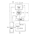
図1は、本発明の実施形態1による表示装置のブロック図である。図2は、本発明の図1の表示パネルの画素構造を示す概念図である。
FIG. 1 is a block diagram of a display device according to
図1及び図2を参照すると、表示装置は、表示パネル100及び表示パネル100を駆動する駆動装置200を含む。
Referring to FIGS. 1 and 2, the display device includes a
表示パネル100は、マトリックス形状に配列された複数の画素を含む。各々の画素は、データ配線の延長方向である第1方向に沿ってその短辺を有し、ゲート配線の延長方向である第2方向に沿ってその長辺を有する。ここで、第1方向は、横方向であり、第2方向は、縦方向であるとする。ここで、マトリックス形状に配列された複数の画素のうち、第1方向に一列に配列された画素を第1画素列と定義し、第2方向に一列に配列された画素を第2画素列と定義する。例えば、第1画素列は、画素行(pixel row)と言及されてもよく、第2画素列は、画素列(pixel column)と言及されてもよい。
複数の第1画素列は、第1方向に配列され、複数の第2画素列は、第2方向に配列される。即ち、1つの画素は、第1画素列の構成要素でありつつ、第2画素列の構成要素でもある。 The plurality of first pixel columns are arranged in the first direction, and the plurality of second pixel columns are arranged in the second direction. That is, one pixel is not only a component of the first pixel column but also a component of the second pixel column.
本実施形態において、第1画素列は、複数の第1画素を含み、第2画素列は、複数の第2画素を含む。 In the present embodiment, the first pixel column includes a plurality of first pixels, and the second pixel column includes a plurality of second pixels.
表示パネル100の複数の単位画素Pの各々は、N個のサブ画素を含む。表示パネル100において、N個のサブ画素が第1方向に沿って配列され、第1画素列は、M個の単位画素Pを含む。また、第2方向に沿ってT個の単位画素Pが配列される。従って、第2画素列は、T個の単位画素Pを含む。N、M、Tは自然数である。本実施形態において、TはMより小さい値を有する。即ち、表示パネル100の横の辺は、表示パネル100の縦の辺より長い。しかし、表示パネル100の横の辺は、表示パネル100の縦の辺より短くてもよい。
Each of the plurality of unit pixels P of the
互いに隣接する一対のデータ配線は第1画素列の第1画素のサブ画素と電気的に接続され、1つのゲート配線は互いに隣接する一対の第2画素列のサブ画素と電気的に接続される。 A pair of data lines adjacent to each other is electrically connected to a sub pixel of the first pixel in the first pixel column, and one gate line is electrically connected to a sub pixel of the pair of second pixel columns adjacent to each other. .
図2に示すように、表示パネル100は、複数のデータ配線(DLm,DLm+1,DLm+2,DLm+3)と、複数のゲート配線(GLn,GLn+1,GLN+2)と、複数の単位画素Pと、を含む。各単位画素Pは、赤色(Red)、緑色(Green)、及び青色(Blue)の画素を含む。m及びnは、自然数である。
As shown in FIG. 2, the
例えば、複数のデータ配線(DLm,DLm+1,DLm+2,DLm+3)は、画素行(pixel row)の方向である第1方向に延び、ゲート配線(GLn,GLn+1,GLn+2)は、第1方向と交差する画素列(pixel column)の方向である第2方向に延びる。第1単位画素P1は、第1方向に配列された第1赤色画素R1、第1緑色画素G1、及び第1青色画素B1を含む。第2単位画素P2は、第1単位画素P1と第1方向に隣接して配置され、第1方向に配列された第2赤色画素R2、第2緑色G2、及び第2青色画素B2を含む。 For example, the plurality of data lines (DLm, DLm + 1, DLm + 2, DLm + 3) extend in the first direction which is the direction of the pixel row, and the gate lines (GLn, GLn + 1, GLn + 2) cross the first direction. It extends in the second direction, which is the direction of the pixel column. The first unit pixel P1 includes a first red pixel R1, a first green pixel G1, and a first blue pixel B1 arranged in the first direction. The second unit pixel P2 includes a second red pixel R2, a second green G2, and a second blue pixel B2, which are arranged adjacent to the first unit pixel P1 in the first direction and are arranged in the first direction.
互いに隣接する一対のデータ配線は、第1方向に延びた1つの第1画素列の第1画素と電気的に接続される。 A pair of adjacent data lines are electrically connected to the first pixel of one first pixel column extending in the first direction.
例えば、第mデータ配線DLmは、隣接する第1画素列の第1赤色画素R1、第2赤色画素R2、及び第2緑色画素G2と電気的に接続され、第m+1データ配線DLm+1は、隣接する第1画素列の第1緑色画素G1、第1青色画素B1及び第2青色画素B2と電気的に接続される。 For example, the mth data line DLm is electrically connected to the first red pixel R1, the second red pixel R2, and the second green pixel G2 of the adjacent first pixel column, and the m + 1th data line DLm + 1 is adjacent. The first green pixel G1, the first blue pixel B1, and the second blue pixel B2 of the first pixel column are electrically connected.
第m+2データ配線DLm+2は、隣接する第1画素列の第1緑色画素G1’、第1青色画素B1’、及び第2青色画素B2’と電気的に接続され、第m+3データ配線DLm+3は、隣接する第1画素列の第1赤色画素R1’、第2赤色画素R2’及び第2緑色画素G2’と電気的に接続される。 The m + 2 data line DLm + 2 is electrically connected to the first green pixel G1 ′, the first blue pixel B1 ′, and the second blue pixel B2 ′ of the adjacent first pixel column, and the m + 3 data line DLm + 3 is adjacent. Are electrically connected to the first red pixel R1 ′, the second red pixel R2 ′ and the second green pixel G2 ′ of the first pixel column.
ここで、データ配線(DLm,DLm+1,DLm+2,DLm+3)には、交互に異なる極性の電圧が印加されてもよい。 Here, voltages having different polarities may be alternately applied to the data lines (DLm, DLm + 1, DLm + 2, DLm + 3).
従って、各第1画素列では、第1方向に沿って第1画素の2つのサブ画素ずつ交互に互いに異なる極性の電圧の印加を受けてもよい。また、各第2画素列の第2画素の各々は、第2方向に沿って交互に異なる極性の電圧の印加を受けてもよい。 Therefore, in each first pixel row, two subpixels of the first pixel may be alternately applied with voltages having different polarities along the first direction. In addition, each of the second pixels in each second pixel column may be applied with a voltage having a different polarity along the second direction.
即ち、表示パネル100は、全体的に2ドット反転駆動してもよい。
That is, the
1つのゲート配線は、第2方向に延びた第2画素列の第2画素と電気的に接続される。 One gate line is electrically connected to the second pixel of the second pixel column extending in the second direction.
例えば、第nゲート配線GLnは、第1赤色画素R1及び第1緑色画素G1と接続される。第n+1ゲート配線GLn+1は、第1青色画素B1及び第2赤色画素R2と接続される。第n+2ゲート配線GLn+2は、第2緑色画素G2及び第2青色画素B2と接続される。
For example, the nth gate line GLn is connected to the first red pixel R1 and the first green pixel G1. The (n + 1) th gate
ここで、第1方向に配列された第k単位画素列(LINE k)及び第k+1単位画素列(LINE k+1)は、3つのゲート配線(GLn,GLn+1,GLn+2)を含む。kは、自然数である。 Here, the k-th unit pixel column (LINE k) and the (k + 1) th unit pixel column (LINE k + 1) arranged in the first direction include three gate lines (GLn, GLn + 1, GLn + 2). k is a natural number.
駆動装置200は、タイミング制御部110、駆動電圧生成部130、ゲート駆動部150、及びデータ駆動部170を含む。
The driving
タイミング制御部110は、外部から同期信号101及びデータ102を受信する。同期信号101は、水平同期信号、垂直同期信号、及び水平同期信号に同期されたデータイネーブル信号(以下、DE信号と称する)を含み、データ102は、赤色、緑色、及び青色のデータを含む。
The
タイミング制御部110は、同期信号101を利用して駆動装置200の駆動タイミングを制御するゲート制御信号及びデータ制御信号を生成する。タイミング制御部110は、データ102を保存する保存部(図示せず)を含む。タイミング制御部110は、保存部の容量を増大させ、データ処理信頼性を向上させるデータ処理方式を通じて、データを表示パネル100の画素構造に応じて処理する。タイミング制御部110のデータ処理方式は、図3、図4、及び図5を参照して詳しく後述する。
The
図4を参照すると、タイミング制御部110は、受信されたDE信号を利用して、M個の単位画素に対応するM×N個の色データの印加を受け、M個の単位画素列のデータを色データに束ねて、分けて処理する。DE信号は、1水平周期Hに対応するパルスと互いに隣接する2つのパルス間に位置するブランクとからなり、ブランクの大きさは可変であってもよい。Mは、2つ以上の自然数である。
Referring to FIG. 4, the
ここで、第1方向に配列されたM×N個の色データは、イメージの1フレームのために必要なデータである。表示パネル100に対応して、色データは第2方向にT列に配列される。本実施形態において、表示パネル100は、M×N×T個の色データを含む。従って、表示パネル100は、M×Tの解像度を有し、フレームを表示する。
Here, the M × N color data arranged in the first direction is data necessary for one frame of the image. Corresponding to the
また、表示パネル100は、T×Mの解像度を示してもよい。
Further, the
例えば、図5に示すように、タイミング制御部110は、受信された2つの単位画素列データを次のように2つの色を表現する色データに束ねて、T×Mの色データを出力する。即ち、赤色、緑色、及び青色データの各々は、2/3Hの間に出力される。以下において、第k単位画素列のデータを第kラインのデータと称する。ここで、データ駆動部170は、受信された色データをアナログ形態のデータ電圧に変換してデータ配線(DLm,DLm+1,DLm+2,DLm+3)に出力する。
For example, as illustrated in FIG. 5, the
駆動電圧生成部130は、外部から受信された電源電圧を利用して、表示装置を駆動するための駆動電圧を生成する。例えば、駆動電圧生成部130は、データ駆動部170にデジタル電源電圧DVDD及びアナログ電源電圧AVDDを提供し、ゲート駆動部150にゲートオン電圧VON及びゲートオフ電圧VOFFを提供する。
The
データ駆動部170は、タイミング制御部110から受信されたデータ制御信号に同期して、データをアナログ形態のデータ電圧に変換して、表示パネル100のデータ配線に出力する。例えば、データ駆動部170は、2/3H周期に受信されるデータをアナログ形態のデータ電圧に変換して複数のデータ配線(DLm,DLm+1,DLm+2,DLm+3)に出力する。データ駆動部170は、図2に示した表示パネル100の画素構造に応じて、第2方向と平行に表示パネル100の一側辺に配置されてもよい。
The
ゲート駆動部150は、タイミング制御部110から受信されたゲート制御信号に同期して、ゲートオン電圧VONを含むゲート信号をゲート配線に順次に出力する。ゲート駆動部150は、図2に示す表示パネル100の画素構造に応じて第1方向と平行に表示パネル100の一側面に配置されてもよい。
The
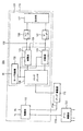
図3は、図1に示した駆動装置のブロック図である。図4及び図5は、図1の表示パネルを駆動するためのデータ処理方式を説明するための概念図である。 FIG. 3 is a block diagram of the driving apparatus shown in FIG. 4 and 5 are conceptual diagrams for explaining a data processing method for driving the display panel of FIG.
図1、図2、図3、図4、及び図5を参照すると、前述したように、駆動装置200は、タイミング制御部110、ゲート駆動部150、及びデータ駆動部170を含む。
Referring to FIGS. 1, 2, 3, 4, and 5, the driving
タイミング制御部110は、図2に示した表示パネルの画素構造に応じて、2つの単位画素列データに含まれた6つの色データを2つずつ処理する。
The
タイミング制御部110は、制御部115、及びデータ処理装置120を含む。
The
制御部115は、受信された垂直同期信号Vs、水平同期信号Hs、及びDE信号を含む同期信号に基づいて、ゲート駆動部150及びデータ駆動部170の駆動を制御する。
The
制御部115は、データ駆動部170に水平開始信号STH、ロード信号TPなどを含むデータ制御信号115aを提供し、ゲート駆動部150に垂直開始信号STV、クロック信号CK、CKBなどを含むゲート制御信号115bを提供する。
The
データ処理装置120は、保存部121、モード判断部122、及びデータ処理部123を含む。保存部121は、タイミング制御部110の外部に実装されてもよい。
The
保存部121は、p番目フレームデータを保存する。ここで、pは、自然数である。
The
モード判断部122は、p番目フレームデータに対応するデータイネーブル信号(DE信号)のパルス数に基づいて、p番目フレームデータの表示モードを判断する。即ち、モード判断部122は、p番目フレームデータに対応するDE信号に基づいて、表示パネル100にディスプレイされる出力画像が非自動回転モードでディスプレイされるのか、または自動回転モードでディスプレイされるのかを判断する。ここで、非自動回転モードは、バイオスモード(BIOS mode)、即ち、ベーシック入/出力システムモードであってもよく、回転モードはウィンドウズモード(Windows(登録商標) mode)であってもよい。ウィンドウズモードは、自動回転機能を有しているが、バイオスモードは自動回転機能を有していない。
The
図2に示す表示パネル100のためのイメージデータは、表示パネルの左側に配置されたゲート駆動ユニット及び表示パネルの上部に配置されたデータ駆動ユニットを含む一般的な表示装置のデータフォーマットとは異なる。例えば、図2に示す表示パネル100は、一般的な表示パネルのデータが回転された形態のフレームデータを表示する。ウィンドウズモードは、表示パネルのタイプに応じて回転されたフレームデータを提供することができ、バイオスモードは回転されたフレームデータを提供することができない。本実施形態において、タイミング制御部110は、回転されていないフレームデータを正常な方向の回転されたフレームデータに変換して提供することができる。
The image data for the
具体的に、モード判断部122は、p番目フレームデータに対応するデータイネーブル信号DEのパルス数に基づいて、表示モードを設定する。
Specifically, the
例えば、図4に示すように、DE信号に対応する解像度がM×Tであれば、即ち、p番目フレームデータに対応するDE信号のパルス数がTであれば、出力された出力画像が非自動回転モードで表示パネル100にディスプレイされるとモード判断部122が判断し、モード判断部122は、表示モードを非自動回転モードに設定する。
For example, as shown in FIG. 4, if the resolution corresponding to the DE signal is M × T, that is, if the number of pulses of the DE signal corresponding to the p-th frame data is T, the output image that is output is non- The
一方、図5に示すようにDE信号に対応する解像度がT×Mであれば、即ち、p番目フレームデータに対応するDE信号のパルス数がMであれば、出力された出力画像が自動回転モードで表示パネル100にディスプレイされるとモード判断部122が判断し、モード判断部122は、表示モードを自動回転モードに設定する。
On the other hand, if the resolution corresponding to the DE signal is T × M as shown in FIG. 5, that is, if the number of pulses of the DE signal corresponding to the p-th frame data is M, the output image output is automatically rotated. When the mode is displayed on the
データ処理部123は、回転部124及び補償部125を含む。
The
表示モードが非自動回転モードである場合、回転部124は、p番目フレームデータを回転させる。
When the display mode is the non-automatic rotation mode, the
例えば、DE信号に対応する解像度がM×Tであれば、回転部124は、p番目フレームデータを回転させる。即ち、出力画像を90°回転させる。90°回転された出力画像に対応する解像度は、T×Mになる。即ち、p番目フレームデータに対応するDE信号のパルス数がMになる。
For example, if the resolution corresponding to the DE signal is M × T, the
ここで、DE信号に対応する解像度がT×Mに変わると、図5に示すように、受信されたDE信号は2/3Hに対応する長さ(period)を有する第1パルスを含む第1DE信号に変換されて、第1DE信号が実質的にデータ駆動部170を図2に示すように駆動させる。
Here, when the resolution corresponding to the DE signal is changed to T × M, as shown in FIG. 5, the received DE signal includes the first DE including a first pulse having a period corresponding to 2 / 3H. As a result, the first DE signal substantially drives the
表示モードが自動回転モードである場合、補償部125は、p番目フレームデータ及び(p+1)番目フレームデータを受信し、p番目フレームデータに基づいて(p+1)番目フレームデータを補償する。
When the display mode is the automatic rotation mode, the
例えば、DE信号に対応する解像度がT×Mであれば、出力画像が自動回転モードで表示パネル100にディスプレイされるとモード判断部122が判断する。これによって、回転部124がp番目フレームデータを回転させずに(即ち、出力画像を90°回転させずに)、補償部125がp番目フレームデータの次に受信される(p+1)番目フレームデータを補償する。
For example, if the resolution corresponding to the DE signal is T × M, the
DE信号に対応する解像度が、T×Mであれば、p番目フレームデータは、既に外部から90°回転された状態で印加されたことを意味する。そのため、データ処理部123は、p番目フレームデータは90°回転させず、保存部121のメモリ空間を利用して(p+1)番目フレームデータを補償する。
If the resolution corresponding to the DE signal is T × M, it means that the p-th frame data has already been applied 90 ° from the outside. Therefore, the
具体的に、補償部125は、p番目フレームデータと(p+1)番目フレームデータとを比較し、ルックアップテーブルでその比較結果に対応する補償値をチェックし、補償値を用いて(p+1)番目フレームデータを補償する。
Specifically, the
続いて、図5に示すように、2/3Hに対応する長さ(period)を有する第1パルスを含む第1DE信号DE1によって、データ駆動部170にデータ102として第1データDATA1が印加される。このように、データ駆動部170が駆動されてもよい。
Subsequently, as shown in FIG. 5, the first data DATA1 is applied to the
従って、DE信号に対応する解像度がT×Mである場合、p番目フレームデータは回転されずに出力画像としてそのまま表示パネル100に表示される。ここで、(p+1)番目フレームデータが補償されるため、観察者は、p番目フレームから(p+1)番目フレームに出力画像が変わることを認識できない。
Therefore, when the resolution corresponding to the DE signal is T × M, the p-th frame data is displayed on the
図1に示すように、表示パネル100は、横の長さが縦の長さより長い横長形状をデフォルトとして有するが、表示パネル100を90°回転させた場合、回転させた後の表示パネル100の横の長さが縦の長さよりも短くなる。従って、90°回転させた表示パネル100に表示される画像は、観察者の立場から見た場合、表示パネル100が90°回転する前に表示された画像から90°回転された画像で表示される。
As shown in FIG. 1, the
このように、表示パネル100を90°回転させる場合、表示パネル100上に表示される画像も90°回転させることによって、観察者は正常な方向の画像を見ることができる。
As described above, when the
ウィンドウズモードの自動回転モードでは、ウィンドウドライバーによってp番目フレームデータが自動的に90°回転され、データ処理部123は、(p+1)番目フレームデータを補償する。バイオスモードの非自動回転モードでは、p番目フレームデータの90°回転をデータ処理部123が実行する。
In the automatic rotation mode of the Windows mode, the p-th frame data is automatically rotated by 90 ° by the window driver, and the
これにより、観察者は、外部の表示モードに関係なく正常な画像を見ることができる。なお、保存部121は、表示モードに応じて使用されることができ、メモリの使用を減らすことができる。
Thereby, the observer can view a normal image regardless of the external display mode. Note that the
データ処理装置120は、エンコーダー126、デコーダー127、及びマルチプレクサをさらに含んでもよい。
The
エンコーダー126は、p番目フレームデータを圧縮しながらエンコードし、圧縮されて小さいサイズを有するエンコードされたp番目フレームデータを保存部121が保存する。
The
デコーダー127は、圧縮エンコードされたp番目フレームデータをデコードして、データ処理部123がデータ処理をする。
The
マルチプレクサ128は、表示モードに応じて、回転部124から出力される90°回転されたp番目フレームデータ又は補償部125から出力される補償された(p+1)番目フレームデータを選択的に出力する。
The
図6は、図1の表示パネルの駆動方式を説明するためのタイミング図である。 FIG. 6 is a timing chart for explaining a driving method of the display panel of FIG.
図1、図2、及び図6を参照すると、データ駆動部170は、第1DE信号DE1に応答して、2/3Hに対応する第1区間T1の間、赤色及び緑色データR1、G1を受信する。データ駆動部170は、タイミング制御部110から提供されたロード信号TPに応答して、第2区間T2の間、赤色及び緑色R1、G1をアナログ形態のデータ電圧に変換してデータ配線(DLm,DLm+1,DLm+2,DLm+3)に出力する。同様に、データ駆動部170は、次の2/3Hの間に受信された青色及び赤色データB1、R2を、ロード信号TPに応答してアナログ形態のデータ電圧に変換してデータ配線(DLm,DLm+1,DLm+2,DLm+3)に出力する。
Referring to FIGS. 1, 2, and 6, the
ゲート駆動部150は、第n〜第n+2ゲート配線(GLn,GLn+1,GLn+2)に第nゲート信号Gn、第n+1ゲート信号Gn+1、第n+2ゲート信号Gn+2を順次に出力する。
The
第nゲート信号Gnは、第kラインの赤色及び緑色データ電圧R1、G1が出力される時点01に同期して第nゲート配線GLnに出力され、第n+1ゲート信号GLn+1は、第kラインの青色データ電圧B1及び第k+1ラインの赤色データ電圧R2が出力される時点02に同期して第n+1ゲート配線GLn+1に出力され、第n+2ゲート信号GLn+2は、第k+1ラインの緑色及び青色データ電圧G2、B2が出力される時点03に同期して第n+2ゲート配線GLn+2に出力される。これによって、第k及び第k+1単位画素列(LINE k,LINE k+1)にデータ電圧が充電される。
The nth gate signal Gn is output to the nth gate line GLn in synchronization with the
図7は、本発明の図1の表示パネルの駆動方法を説明するためのフローチャートである。 FIG. 7 is a flowchart for explaining a method of driving the display panel of FIG. 1 according to the present invention.
図1、図3及び図7を参照すると、補償部125及びエンコーダー126は、p番目フレームデータを受信する(ステップS110)。
Referring to FIGS. 1, 3, and 7, the
エンコーダー126は、p番目フレームデータを圧縮エンコードする(ステップS120)。保存部121は、圧縮エンコードされたp番目フレームデータを保存する(ステップS130)。保存部121は、圧縮エンコードされたp番目フレームデータを保存することによってメモリエリアを節約することができる。
The
補償部125及び回転部124がp番目フレームデータを処理することができるように、デコーダー127は保存されたp番目フレームデータをデコードする(ステップS140)
The
モード判断部122は、p番目フレームデータに対応するDE信号のパルス数に基づいて、表示パネル100にディスプレイされる出力画像が非自動回転モードでディスプレイされるか、または自動回転モードでディスプレイされるか、表示モードを判断する(ステップS150)。
The
表示モードが非自動回転モードであれば、回転部124は、p番目フレームデータを回転させる(ステップS160)。
If the display mode is the non-automatic rotation mode, the
表示パネルモードが自動回転モードであれば、補償部125は、(p+1)番目フレームデータを受信し(ステップS170)、p番目フレームデータに基づいて(p+1)番目フレームデータを補償する(ステップS180)。
If the display panel mode is the automatic rotation mode, the
マルチプレクサ128は、表示モードに応じて、回転部124から出力される回転されたp番目フレームデータ、又は補償部125から出力される補償された(p+1)番目フレームデータを選択的に出力する。
The
本発明の実施形態1によれば、DE信号に対応する解像度がT×Mであれば、p番目フレームデータは、既に外部で90°回転された状態で印加されたことを意味する。そのため、p番目フレームデータは90°回転されることはなく、保存部121のメモリ空間を利用して、(p+1)番目フレームデータが補償される。従って、表示パネル100の表示品質が向上される。
According to
実施形態2
図8は、実施形態2により表示パネルの画素構造を示す概念図である。
FIG. 8 is a conceptual diagram illustrating a pixel structure of a display panel according to the second embodiment.
実施形態2による表示装置のブロック図は、図1に示した実施形態1による表示装置と実質的に同一である。従って、対応する要素に対しては、対応する参照番号を使用し、重複する説明は省略する。図1及び図8を参照すると、表示装置は、表示パネル300及び表示パネル300を駆動する駆動装置200を含む。
The block diagram of the display device according to the second embodiment is substantially the same as the display device according to the first embodiment shown in FIG. Accordingly, corresponding reference numbers are used for corresponding elements, and redundant description is omitted. Referring to FIGS. 1 and 8, the display device includes a
表示パネル300は、N個の画素からなる単位画素が配列された単位画素列が定義され、第1方向に画素が配列された第1画素列と第2方向に配列された第2画素列とを含み、互いに隣接する一対のデータ配線は、第1画素列と電気的に接続され、1つのゲート配線は、互いに隣接する一対の第2画素列と電気的に接続される。Nは、自然数である。
The
例えば、図2に示すように、表示パネル300は、複数のデータ配線(DLm,DLm+1,DLm+2,DLm+3)と、複数のゲート配線(GLn,GLn+1,GLn+2)と、複数の単位画素Pとを含む。各単位画素Pは、赤色(Red)、緑色(Green)、及び青色(Blue)の画素を含む。n及びmは、自然数である。
For example, as shown in FIG. 2, the
例えば、データ配線(DLm,DLm+1,DLm+2,DLm+3)は、第1方向に延長され、ゲート配線(GLn,GLn+1,GLn+2)は、第1方向と交差する第2方向に延長される。第1単位画素P1は、第1方向に配列された第1赤色画素R1、第1緑色画素G1、及び第1青色画素B1を含む。第2単位画素P2は、第1単位画素P1と第1方向に隣接するように配置され、第1方向に配列された第2赤色画素R2、第2緑色画素G2及び第2青色画素B2を含む。 For example, the data lines (DLm, DLm + 1, DLm + 2, DLm + 3) are extended in the first direction, and the gate lines (GLn, GLn + 1, GLn + 2) are extended in the second direction intersecting the first direction. The first unit pixel P1 includes a first red pixel R1, a first green pixel G1, and a first blue pixel B1 arranged in the first direction. The second unit pixel P2 includes a second red pixel R2, a second green pixel G2, and a second blue pixel B2 that are arranged adjacent to the first unit pixel P1 in the first direction and are arranged in the first direction. .
図8を参照すると、複数のデータ配線は規則性を有し、第1方向に配列された画素と電気的に接続される。即ち、隣接する一対のデータ配線は、第1方向に延長された第1画素列の第1画素のサブ画素と1つずつ交互に電気的に接続される。 Referring to FIG. 8, the plurality of data lines have regularity and are electrically connected to the pixels arranged in the first direction. That is, a pair of adjacent data lines are electrically connected alternately to the sub-pixels of the first pixel in the first pixel column extended in the first direction one by one.
例えば、第mデータ配線DLmは、隣接する第1画素列の第1赤色画素R1、第1青色画素B1及び第2緑色画素G2と電気的に接続され、第m+1データ配線DLm+1は、隣接する第1画素列の第1緑色画素G1、第2赤色画素R2及び第2青色画素B2と電気的に接続される。 For example, the mth data line DLm is electrically connected to the first red pixel R1, the first blue pixel B1, and the second green pixel G2 of the adjacent first pixel column, and the m + 1th data line DLm + 1 is adjacent to the first red pixel R1, the first blue pixel B1, and the second green pixel G2. The first green pixel G1, the second red pixel R2, and the second blue pixel B2 in one pixel column are electrically connected.
第m+2データ配線DLm+2は、隣接する第1画素列の第1緑色画素G1’、第2赤色画素R2’及び第2青色画素B2’と電気的に接続され、第m+3データ配線DLm+3は、隣接する第1画素列の第1赤色画素R1’、第1青色画素B1’及び第2緑色画素G2’と電気的に接続される。 The m + 2 data line DLm + 2 is electrically connected to the first green pixel G1 ′, the second red pixel R2 ′, and the second blue pixel B2 ′ of the adjacent first pixel column, and the m + 3 data line DLm + 3 is adjacent. The first red pixel R1 ′, the first blue pixel B1 ′, and the second green pixel G2 ′ of the first pixel column are electrically connected.
ここで、データ配線(DLm,DLm+1,DLm+2,DLm+3)には交互に異なる極性の電圧が印加されてもよい。 Here, voltages having different polarities may be alternately applied to the data lines (DLm, DLm + 1, DLm + 2, DLm + 3).
従って、各第1画素列の第1画素は、第1方向に交互に互いに異なる極性の電圧の印加を受けてもよい。また、各第2画素列の第2画素は、第2方向に交互に、異なる極性の電圧の印加を受けてもよい。 Accordingly, the first pixels of each first pixel column may be alternately applied with voltages having different polarities in the first direction. In addition, the second pixels of each second pixel column may be alternately applied with voltages having different polarities in the second direction.
即ち、表示パネルは、全体的に1ドット反転駆動で駆動されてもよい。 That is, the display panel may be driven by 1-dot inversion driving as a whole.
1つのゲート配線は、第2方向に延長された第2画素列の第2画素と電気的に接続される。 One gate line is electrically connected to the second pixel of the second pixel column extended in the second direction.
例えば、第nゲート配線GLnは、第1赤色画素R1及び第1緑色画素G1と接続され、第n+1ゲート配線GLn+1は、第1青色画素B1と及び第2赤色画素R2と接続され、第n+2ゲート配線GLn+2は、第2緑色画素G2及び第2青色画素B2と接続される。
For example, the nth gate line GLn is connected to the first red pixel R1 and the first green pixel G1, and the n + 1th gate
ここで、第2方向に配列された第k単位画素列(LINE k)及びk+1単位画素列(LINE k+1)は、3つのゲート配線(GLn,GLn+1,GLn+2)と電気的に接続される。kは、自然数である。 Here, the k-th unit pixel column (LINE k) and the k + 1 unit pixel column (LINE k + 1) arranged in the second direction are electrically connected to three gate lines (GLn, GLn + 1, GLn + 2). k is a natural number.
従って、隣接する一対の単位画素列は3つのゲート配線と電気的に接続されるため、ゲート配線の個数を減らすことができ、データ電圧が各々充電される時間が増加する。 Accordingly, since a pair of adjacent unit pixel columns are electrically connected to the three gate lines, the number of gate lines can be reduced, and the time during which each data voltage is charged increases.
図1に示すように、駆動装置200は、タイミング制御部110、駆動電圧生成部130、ゲート駆動部150及びデータ駆動部170を含む。
As shown in FIG. 1, the driving
タイミング制御部110は、受信された2つの単位画素列データを次のように2つの色データに各々束ねて出力する。第k及び第k+1単位画素列のデータは2Hの間に出力され、初めの2/3Hの間に第k単位画素列の赤色及び緑色データが出力され、次の2/3Hの間に第k単位画素列の青色データと第k+1単位画素列の赤色データとが出力され、次の2/3Hの間に第k+1単位画素列の緑色及び青色データが出力される。本発明の実施形態2による駆動装置のブロック図は、図3に示した実施形態1による駆動装置のブロック図と実質的に同一である。従って、対応する要素に対しては、対応する参照番号を使用し、重複する説明は省略する。
The
本発明の実施形態2による表示パネルを駆動するためのデータ処理方式を説明するための概念図は、図4及び図5に示すデータ処理方式を説明するための概念図と実質的に同一である。従って、対応する要素に対しては、対応する参照番号を使用し、重複する説明は省略する。 The conceptual diagram for explaining the data processing method for driving the display panel according to the second embodiment of the present invention is substantially the same as the conceptual diagram for explaining the data processing method shown in FIGS. . Accordingly, corresponding reference numbers are used for corresponding elements, and redundant description is omitted.
本発明の実施形態2による表示パネルの駆動方式を説明するためのタイミング図及びフローチャートは、図6及び図7に示すタイミング図及びフローチャートと実質的に同一である。従って、対応する要素に対しては対応する参照番号を使用し、重複する説明は省略する。 The timing diagrams and flowcharts for explaining the driving method of the display panel according to the second embodiment of the present invention are substantially the same as the timing diagrams and flowcharts shown in FIGS. Accordingly, corresponding reference numbers are used for corresponding elements, and redundant description is omitted.
本発明の実施形態2によると、DE信号に対応する解像度がT×Mであれば、p番目フレームデータは90°回転されることがなく、保存部121のメモリ空間を利用して(p+1)番目フレームデータが補償される。これにより、1ドット反転駆動で駆動される表示パネル300の表示品質が向上される。
According to the second embodiment of the present invention, if the resolution corresponding to the DE signal is T × M, the p-th frame data is not rotated by 90 °, and the memory space of the
本発明の実施形態によれば、出力画像が横モードでディスプレイされる場合、出力画像を90°回転させて表示パネルに表示し、出力画像が自動回転モードでディスプレイされる場合、フレームが変わるときに出力画像が変わることが観察者に認識されないように出力画像を補償する。従って、出力画像が常に正常方向に表示され、出力画像を回転させない場合には、出力を補償することによって、表示パネルの表示品質を向上させることができる。 According to the embodiment of the present invention, when the output image is displayed in the horizontal mode, the output image is rotated by 90 ° and displayed on the display panel, and when the output image is displayed in the automatic rotation mode, the frame is changed. The output image is compensated so that the observer will not recognize that the output image will change. Therefore, when the output image is always displayed in the normal direction and the output image is not rotated, the display quality of the display panel can be improved by compensating the output.
以上、図面を参照しながら本発明の好適な実施形態について詳細に説明したが、本発明はかかる例に限定されない。本発明の属する技術の分野における通常の知識を有する者であれば、特徴請求の範囲に記載された技術的思想の範疇内において、各種の変更例または修正例に想到し得ることは明らかであり、これらについても、当然に本発明の技術的範囲に属するものと了解される。 The preferred embodiments of the present invention have been described in detail above with reference to the drawings, but the present invention is not limited to such examples. It is obvious that a person having ordinary knowledge in the technical field to which the present invention pertains can make various changes or modifications within the scope of the technical idea described in the claims. Of course, it is understood that these also belong to the technical scope of the present invention.
110 タイミング制御部
115 制御部
120 データ処理装置
121 保存部
122 モード判断部
123 データ処理部
124 回転部
125 補償部
126 エンコーダー
127 デコーダー
128 マルチプレクサ
150 データ駆動部
170 ゲート駆動部
110
Claims (22)
前記p番目フレームデータに対応するデータイネーブル信号のパルス数に基づいて前記p番目フレームデータの表示モードが非自動回転モードであるか又は自動回転モードであるかを判断し、
判断された表示モードに応じて前記p番目フレームデータを処理すること、
を含むデータ処理方法。 Save the pth frame data (p is a natural number)
Determining whether the display mode of the p-th frame data is a non-automatic rotation mode or an automatic rotation mode based on the number of pulses of a data enable signal corresponding to the p-th frame data;
Processing the p-th frame data according to the determined display mode;
Data processing method.
保存された前記p番目フレームデータを回転させること、を含むことを特徴とする請求項1に記載のデータ処理方法。 When the determined display mode is the non-automatic rotation mode, the processing of the p-th frame data is
The data processing method according to claim 1, further comprising rotating the stored p-th frame data.
保存された前記p番目フレームデータを利用して、(p+1)番目フレームデータを補償すること、を含むことを特徴とする請求項2に記載のデータ処理方法。 When the p-th frame data is in the automatic rotation mode, the processing of the p-th frame data is
The data processing method according to claim 2, further comprising: compensating the (p + 1) th frame data using the stored pth frame data.
前記p番目フレームデータを処理する前に、圧縮エンコードされた前記p番目フレームデータを圧縮デコードすること、をさらに含むことを特徴とする請求項1に記載のデータ処理方法。 Compressing and encoding the pth frame data before storing the pth frame data;
The data processing method according to claim 1, further comprising: compressing and decoding the compressed and encoded p-th frame data before processing the p-th frame data.
前記p番目フレームデータに対応するデータイネーブル信号のパルス数に基づいて前記p番目フレームデータの表示モードが非自動回転モードであるか又は自動回転モードであるかを判断するモード判断部と、
判断された表示モードに応じて表示パネルに対応する前記p番目フレームデータを処理するデータ処理部と、
を含むデータ処理装置。 a storage unit for storing p-th frame data (p is a natural number);
A mode determination unit that determines whether the display mode of the p-th frame data is a non-automatic rotation mode or an automatic rotation mode based on the number of pulses of a data enable signal corresponding to the p-th frame data;
A data processing unit for processing the p-th frame data corresponding to the display panel according to the determined display mode;
Including a data processing apparatus.
圧縮エンコードされた前記p番目フレームデータを圧縮デコードして前記データ処理部に提供するデコーダーと、をさらに含むことを特徴とする請求項8に記載のデータ処理装置。 An encoder that compresses and encodes the p-th frame data and provides it to the storage unit;
9. The data processing apparatus according to claim 8, further comprising a decoder that compresses and decodes the compression-encoded p-th frame data and provides the data to the data processing unit.
前記表示モードが前記非自動回転モードの場合、前記p番目フレームデータを回転させる回転部と、
前記p表示モードが前記自動回転モードの場合、前記p番目フレームデータに基づいて(p+1)番目フレームデータを補償する補償部と、を含むことを特徴とする請求項8に記載のデータ処理装置。 The data processing unit
When the display mode is the non-automatic rotation mode, a rotation unit that rotates the p-th frame data;
The data processing apparatus according to claim 8, further comprising: a compensation unit that compensates the (p + 1) th frame data based on the pth frame data when the p display mode is the automatic rotation mode.
p番目フレームデータ(pは自然数)に対応するデータイネーブル信号のパルス数に基づいて判断された前記p番目フレームデータの表示モードに応じて、前記p番目フレームデータを処理するデータ処理装置と、
を含む表示装置。 A display panel including a data wiring extending in a horizontal direction and a gate wiring extending in a vertical direction shorter than the horizontal direction;
a data processing device that processes the p-th frame data according to the display mode of the p-th frame data determined based on the number of pulses of the data enable signal corresponding to the p-th frame data (p is a natural number);
Display device.
前記p番目フレームデータを保存する保存部と、
前記データイネーブル信号のパルス数に基づいて前記表示モードが非自動回転モードであるか又は自動回転モードであるかを判断するモード判断部と、
前記表示モード部が前記非自動回転モードである場合、前記p番目フレームデータを回転させる回転部と、
前記表示モードが前記自動回転モードである場合、前記p番目フレームデータに基づいて前記(p+1)番目フレームデータを補償する補償部と、を含むことを特徴とする請求項15に記載の表示装置。 The data processing device includes:
A storage unit for storing the p-th frame data;
A mode determination unit that determines whether the display mode is a non-automatic rotation mode or an automatic rotation mode based on the number of pulses of the data enable signal;
When the display mode unit is the non-automatic rotation mode, a rotation unit that rotates the p-th frame data;
The display device according to claim 15, further comprising: a compensation unit that compensates the (p + 1) -th frame data based on the p-th frame data when the display mode is the automatic rotation mode.
一対のデータ配線は、1つの第1画素列と電気的に接続され、1つのゲート配線は、一対の第2画素列と電気的に接続されることを特徴とする請求項16に記載の表示装置。 The display panel includes a first pixel column in which a plurality of first pixels are arranged in the horizontal direction, and a second pixel column in which a plurality of second pixels are arranged in the vertical direction,
The display according to claim 16, wherein the pair of data lines are electrically connected to one first pixel column, and the one gate line is electrically connected to the pair of second pixel columns. apparatus.
Applications Claiming Priority (1)
| Application Number | Priority Date | Filing Date | Title |
|---|---|---|---|
| KR1020090003174A KR20100083873A (en) | 2009-01-15 | 2009-01-15 | Method of processing data, apparatus for performing the same and display apparatus having the apparatus |
Publications (1)
| Publication Number | Publication Date |
|---|---|
| JP2010164949A true JP2010164949A (en) | 2010-07-29 |
Family
ID=42115342
Family Applications (1)
| Application Number | Title | Priority Date | Filing Date |
|---|---|---|---|
| JP2009249379A Pending JP2010164949A (en) | 2009-01-15 | 2009-10-29 | Method for processing data, apparatus for performing the method, and display apparatus having the driving apparatus |
Country Status (4)
| Country | Link |
|---|---|
| US (1) | US8400475B2 (en) |
| EP (1) | EP2209108A3 (en) |
| JP (1) | JP2010164949A (en) |
| KR (1) | KR20100083873A (en) |
Families Citing this family (8)
| Publication number | Priority date | Publication date | Assignee | Title |
|---|---|---|---|---|
| KR101579815B1 (en) * | 2008-11-27 | 2015-12-28 | 삼성디스플레이 주식회사 | Liquid crystal display |
| KR101535919B1 (en) * | 2008-12-12 | 2015-07-13 | 삼성디스플레이 주식회사 | Method of processing data, driving apparatus for performing the same and display apparatus having the driving apparatus |
| KR101490789B1 (en) * | 2008-12-18 | 2015-02-06 | 삼성디스플레이 주식회사 | Liqiud crystal display |
| KR101607293B1 (en) * | 2010-01-08 | 2016-03-30 | 삼성디스플레이 주식회사 | Method of processing data, and display apparatus performing for the method |
| CN104537974B (en) * | 2015-01-04 | 2017-04-05 | 京东方科技集团股份有限公司 | Data acquisition submodule and method, data processing unit, system and display device |
| CN105895049B (en) * | 2016-07-01 | 2018-04-10 | 京东方科技集团股份有限公司 | A kind of display panel and display device |
| US10950679B1 (en) | 2017-09-07 | 2021-03-16 | Apple Inc. | Display having vertically driven gate and data paths |
| US20190204699A1 (en) * | 2017-12-29 | 2019-07-04 | Shenzhen China Star Optoelectronics Semiconductor Display Technology Co., Ltd. | Liquid crystal display |
Citations (6)
| Publication number | Priority date | Publication date | Assignee | Title |
|---|---|---|---|---|
| JPH03249695A (en) * | 1990-02-28 | 1991-11-07 | Fujitsu Ltd | Freely crisscrossed display device |
| JPH0772826A (en) * | 1993-01-22 | 1995-03-17 | Nec Home Electron Ltd | Liquid crystal display device |
| JPH10197894A (en) * | 1996-12-28 | 1998-07-31 | Casio Comput Co Ltd | Liquid crystal display device and driving method for liquid crystal display device |
| JP2005122179A (en) * | 2003-10-16 | 2005-05-12 | Samsung Electronics Co Ltd | Display device and driving method thereof |
| JP2005148364A (en) * | 2003-11-14 | 2005-06-09 | Casio Comput Co Ltd | Display system |
| JP2008210143A (en) * | 2007-02-26 | 2008-09-11 | Sony Corp | Image processing system, information processing apparatus, image processing method and program |
Family Cites Families (13)
| Publication number | Priority date | Publication date | Assignee | Title |
|---|---|---|---|---|
| JP2000284761A (en) | 1999-03-31 | 2000-10-13 | Advanced Display Inc | Display device and interface circuit for display device |
| KR100327369B1 (en) | 1999-07-31 | 2002-03-06 | 구자홍 | Apparatus and method for interfacing video information of computer system |
| KR100848092B1 (en) * | 2002-03-06 | 2008-07-24 | 삼성전자주식회사 | A Liquid Crystal Display and A Driving Method Thereof |
| JP3852773B2 (en) | 2002-11-29 | 2006-12-06 | 株式会社ナナオ | Display method, display system, display device, and interface device |
| US7050071B2 (en) * | 2003-05-30 | 2006-05-23 | Intel Corporation | Layered rotational graphics driver |
| KR100580174B1 (en) | 2003-08-21 | 2006-05-16 | 삼성전자주식회사 | Rotatable display apparatus and method for adjusting display screen |
| KR101030657B1 (en) | 2003-12-19 | 2011-04-20 | 사천홍시현시기건유한공사 | Flat display panel and image display method |
| US20050275665A1 (en) | 2004-06-14 | 2005-12-15 | Keith Kejser | System and method for efficiently supporting image rotation modes by utilizing a display controller |
| KR100613614B1 (en) * | 2004-12-16 | 2006-08-21 | 삼성전자주식회사 | Apparatus for generating image to express input image by the best mode and method of thereof |
| TWI279736B (en) | 2005-03-11 | 2007-04-21 | Himax Tech Ltd | Integrated video control chipset |
| KR20070049923A (en) | 2005-11-09 | 2007-05-14 | 엘지.필립스 엘시디 주식회사 | Thin film transistor panel using liquid crystal display and liquid crystal display apparatus comprising the same |
| KR20070070748A (en) | 2005-12-29 | 2007-07-04 | 엘지.필립스 엘시디 주식회사 | Liquid crystal display |
| TWI397055B (en) * | 2007-05-28 | 2013-05-21 | Realtek Semiconductor Corp | Mode detection circuit and method |
-
2009
- 2009-01-15 KR KR1020090003174A patent/KR20100083873A/en not_active Application Discontinuation
- 2009-08-19 US US12/543,734 patent/US8400475B2/en not_active Expired - Fee Related
- 2009-09-04 EP EP09011360A patent/EP2209108A3/en not_active Ceased
- 2009-10-29 JP JP2009249379A patent/JP2010164949A/en active Pending
Patent Citations (6)
| Publication number | Priority date | Publication date | Assignee | Title |
|---|---|---|---|---|
| JPH03249695A (en) * | 1990-02-28 | 1991-11-07 | Fujitsu Ltd | Freely crisscrossed display device |
| JPH0772826A (en) * | 1993-01-22 | 1995-03-17 | Nec Home Electron Ltd | Liquid crystal display device |
| JPH10197894A (en) * | 1996-12-28 | 1998-07-31 | Casio Comput Co Ltd | Liquid crystal display device and driving method for liquid crystal display device |
| JP2005122179A (en) * | 2003-10-16 | 2005-05-12 | Samsung Electronics Co Ltd | Display device and driving method thereof |
| JP2005148364A (en) * | 2003-11-14 | 2005-06-09 | Casio Comput Co Ltd | Display system |
| JP2008210143A (en) * | 2007-02-26 | 2008-09-11 | Sony Corp | Image processing system, information processing apparatus, image processing method and program |
Also Published As
| Publication number | Publication date |
|---|---|
| EP2209108A3 (en) | 2010-09-01 |
| KR20100083873A (en) | 2010-07-23 |
| US20100177107A1 (en) | 2010-07-15 |
| EP2209108A2 (en) | 2010-07-21 |
| US8400475B2 (en) | 2013-03-19 |
Similar Documents
| Publication | Publication Date | Title |
|---|---|---|
| JP2010164949A (en) | Method for processing data, apparatus for performing the method, and display apparatus having the driving apparatus | |
| CN101097310B (en) | Liquid crystal display device and method for driving the same | |
| JP5419321B2 (en) | Display device | |
| CN106097947B (en) | It is capable of the display device and its driving method of driven at low speed | |
| US8054266B2 (en) | Display device, driving apparatus for display device, and driving method of display device | |
| JP4501525B2 (en) | Display device and drive control method thereof | |
| JP2006243185A (en) | Liquid crystal display apparatus suitable for displaying moving image | |
| US20060227628A1 (en) | Display driver and display driving method | |
| US20110102389A1 (en) | Display apparatus | |
| JP2006058890A (en) | Liquid crystal display apparatus and its driving method | |
| US10885859B2 (en) | Display device and image determination device | |
| US20100134533A1 (en) | Unit and method of controlling frame rate and liquid crystal display device using the same | |
| JP5132037B2 (en) | Display panel and driving method thereof | |
| US20070195052A1 (en) | Source driving apparatus, method of driving the same, display device having the same and method of driving the same | |
| US20050162369A1 (en) | Apparatus and method of driving display device | |
| JP5305570B2 (en) | Display device | |
| TW200629207A (en) | Liquid crystal display and driving method thereof | |
| US8659610B2 (en) | Liquid crystal display and method of driving the same | |
| US7724268B2 (en) | Liquid crystal display | |
| US10621937B2 (en) | Liquid crystal display device and method of driving the same | |
| US7782289B2 (en) | Timing controller for controlling pixel level multiplexing display panel | |
| JP2003157060A (en) | Display driving method and display device | |
| JP2003131630A (en) | Liquid crystal display device | |
| JP5306067B2 (en) | Liquid crystal display | |
| JP2010102151A (en) | Electrooptical device, electronic device, and driving method for electrooptical device |
Legal Events
| Date | Code | Title | Description |
|---|---|---|---|
| A621 | Written request for application examination |
Free format text: JAPANESE INTERMEDIATE CODE: A621 Effective date: 20120322 |
|
| A711 | Notification of change in applicant |
Free format text: JAPANESE INTERMEDIATE CODE: A712 Effective date: 20121213 |
|
| A521 | Request for written amendment filed |
Free format text: JAPANESE INTERMEDIATE CODE: A523 Effective date: 20130301 |
|
| A977 | Report on retrieval |
Free format text: JAPANESE INTERMEDIATE CODE: A971007 Effective date: 20130716 |
|
| A131 | Notification of reasons for refusal |
Free format text: JAPANESE INTERMEDIATE CODE: A131 Effective date: 20130723 |
|
| A521 | Request for written amendment filed |
Free format text: JAPANESE INTERMEDIATE CODE: A523 Effective date: 20131023 |
|
| A131 | Notification of reasons for refusal |
Free format text: JAPANESE INTERMEDIATE CODE: A131 Effective date: 20140422 |
|
| A601 | Written request for extension of time |
Free format text: JAPANESE INTERMEDIATE CODE: A601 Effective date: 20140722 |
|
| A602 | Written permission of extension of time |
Free format text: JAPANESE INTERMEDIATE CODE: A602 Effective date: 20140725 |
|
| A601 | Written request for extension of time |
Free format text: JAPANESE INTERMEDIATE CODE: A601 Effective date: 20140822 |
|
| A602 | Written permission of extension of time |
Free format text: JAPANESE INTERMEDIATE CODE: A602 Effective date: 20140827 |
|
| A02 | Decision of refusal |
Free format text: JAPANESE INTERMEDIATE CODE: A02 Effective date: 20141118 |