JP2010154792A - Co2 incubator - Google Patents
Co2 incubator Download PDFInfo
- Publication number
- JP2010154792A JP2010154792A JP2008334357A JP2008334357A JP2010154792A JP 2010154792 A JP2010154792 A JP 2010154792A JP 2008334357 A JP2008334357 A JP 2008334357A JP 2008334357 A JP2008334357 A JP 2008334357A JP 2010154792 A JP2010154792 A JP 2010154792A
- Authority
- JP
- Japan
- Prior art keywords
- chamber
- ozone
- sensor
- incubator
- temperature
- Prior art date
- Legal status (The legal status is an assumption and is not a legal conclusion. Google has not performed a legal analysis and makes no representation as to the accuracy of the status listed.)
- Pending
Links
- CBENFWSGALASAD-UHFFFAOYSA-N Ozone Chemical compound [O-][O+]=O CBENFWSGALASAD-UHFFFAOYSA-N 0.000 claims abstract description 84
- 238000010438 heat treatment Methods 0.000 claims abstract description 5
- XLYOFNOQVPJJNP-UHFFFAOYSA-N water Substances O XLYOFNOQVPJJNP-UHFFFAOYSA-N 0.000 claims description 7
- 238000001514 detection method Methods 0.000 claims description 6
- 238000003756 stirring Methods 0.000 claims description 2
- 230000001954 sterilising effect Effects 0.000 abstract description 25
- 238000004659 sterilization and disinfection Methods 0.000 abstract description 24
- 239000007789 gas Substances 0.000 description 48
- 238000000034 method Methods 0.000 description 6
- 238000000354 decomposition reaction Methods 0.000 description 4
- 238000012856 packing Methods 0.000 description 4
- 229910001220 stainless steel Inorganic materials 0.000 description 4
- 239000010935 stainless steel Substances 0.000 description 4
- 238000012258 culturing Methods 0.000 description 3
- 239000002994 raw material Substances 0.000 description 3
- CURLTUGMZLYLDI-UHFFFAOYSA-N Carbon dioxide Chemical compound O=C=O CURLTUGMZLYLDI-UHFFFAOYSA-N 0.000 description 2
- 238000004140 cleaning Methods 0.000 description 2
- 238000009833 condensation Methods 0.000 description 2
- 230000005494 condensation Effects 0.000 description 2
- 238000010586 diagram Methods 0.000 description 2
- 230000000694 effects Effects 0.000 description 2
- 244000005700 microbiome Species 0.000 description 2
- LFQSCWFLJHTTHZ-UHFFFAOYSA-N Ethanol Chemical compound CCO LFQSCWFLJHTTHZ-UHFFFAOYSA-N 0.000 description 1
- MHAJPDPJQMAIIY-UHFFFAOYSA-N Hydrogen peroxide Chemical compound OO MHAJPDPJQMAIIY-UHFFFAOYSA-N 0.000 description 1
- 241000700605 Viruses Species 0.000 description 1
- QVGXLLKOCUKJST-UHFFFAOYSA-N atomic oxygen Chemical compound [O] QVGXLLKOCUKJST-UHFFFAOYSA-N 0.000 description 1
- 229910002092 carbon dioxide Inorganic materials 0.000 description 1
- 239000001569 carbon dioxide Substances 0.000 description 1
- 238000011109 contamination Methods 0.000 description 1
- 239000000645 desinfectant Substances 0.000 description 1
- 239000011810 insulating material Substances 0.000 description 1
- 239000002184 metal Substances 0.000 description 1
- 230000001590 oxidative effect Effects 0.000 description 1
- 239000001301 oxygen Substances 0.000 description 1
- 229910052760 oxygen Inorganic materials 0.000 description 1
- 238000005949 ozonolysis reaction Methods 0.000 description 1
- 239000005341 toughened glass Substances 0.000 description 1
Images
Classifications
-
- C—CHEMISTRY; METALLURGY
- C12—BIOCHEMISTRY; BEER; SPIRITS; WINE; VINEGAR; MICROBIOLOGY; ENZYMOLOGY; MUTATION OR GENETIC ENGINEERING
- C12M—APPARATUS FOR ENZYMOLOGY OR MICROBIOLOGY; APPARATUS FOR CULTURING MICROORGANISMS FOR PRODUCING BIOMASS, FOR GROWING CELLS OR FOR OBTAINING FERMENTATION OR METABOLIC PRODUCTS, i.e. BIOREACTORS OR FERMENTERS
- C12M37/00—Means for sterilizing, maintaining sterile conditions or avoiding chemical or biological contamination
-
- C—CHEMISTRY; METALLURGY
- C12—BIOCHEMISTRY; BEER; SPIRITS; WINE; VINEGAR; MICROBIOLOGY; ENZYMOLOGY; MUTATION OR GENETIC ENGINEERING
- C12M—APPARATUS FOR ENZYMOLOGY OR MICROBIOLOGY; APPARATUS FOR CULTURING MICROORGANISMS FOR PRODUCING BIOMASS, FOR GROWING CELLS OR FOR OBTAINING FERMENTATION OR METABOLIC PRODUCTS, i.e. BIOREACTORS OR FERMENTERS
- C12M41/00—Means for regulation, monitoring, measurement or control, e.g. flow regulation
- C12M41/12—Means for regulation, monitoring, measurement or control, e.g. flow regulation of temperature
- C12M41/14—Incubators; Climatic chambers
-
- C—CHEMISTRY; METALLURGY
- C12—BIOCHEMISTRY; BEER; SPIRITS; WINE; VINEGAR; MICROBIOLOGY; ENZYMOLOGY; MUTATION OR GENETIC ENGINEERING
- C12M—APPARATUS FOR ENZYMOLOGY OR MICROBIOLOGY; APPARATUS FOR CULTURING MICROORGANISMS FOR PRODUCING BIOMASS, FOR GROWING CELLS OR FOR OBTAINING FERMENTATION OR METABOLIC PRODUCTS, i.e. BIOREACTORS OR FERMENTERS
- C12M41/00—Means for regulation, monitoring, measurement or control, e.g. flow regulation
- C12M41/30—Means for regulation, monitoring, measurement or control, e.g. flow regulation of concentration
- C12M41/34—Means for regulation, monitoring, measurement or control, e.g. flow regulation of concentration of gas
Landscapes
- Chemical & Material Sciences (AREA)
- Life Sciences & Earth Sciences (AREA)
- Health & Medical Sciences (AREA)
- Wood Science & Technology (AREA)
- Organic Chemistry (AREA)
- Engineering & Computer Science (AREA)
- Bioinformatics & Cheminformatics (AREA)
- Zoology (AREA)
- Biomedical Technology (AREA)
- Sustainable Development (AREA)
- Microbiology (AREA)
- Biotechnology (AREA)
- Biochemistry (AREA)
- General Engineering & Computer Science (AREA)
- General Health & Medical Sciences (AREA)
- Genetics & Genomics (AREA)
- Analytical Chemistry (AREA)
- Molecular Biology (AREA)
- Physics & Mathematics (AREA)
- Thermal Sciences (AREA)
- Apparatus Associated With Microorganisms And Enzymes (AREA)
Abstract
Description
本発明は、CO2インキュベータに関する。 The present invention relates to a CO 2 incubator.
被培養体を収納するチャンバーの内部に二酸化炭素(CO2)ガスを供給するための手段と、チャンバーの内部のCO2ガスの濃度を検出するためのセンサとを備え、CO2ガスの濃度に応じて、CO2ガスの供給量を制御するCO2インキュベータ(以後「インキュベータ」と略称する)が知られている。 A means for supplying carbon dioxide (CO 2 ) gas to the inside of the chamber for housing the culture object and a sensor for detecting the concentration of CO 2 gas inside the chamber are provided, and the concentration of CO 2 gas is adjusted. Accordingly, a CO 2 incubator (hereinafter abbreviated as “incubator”) for controlling the supply amount of CO 2 gas is known.
このようなインキュベータを用いて被培養体を培養した後にこれを変更する場合、細胞や微生物等の先の被培養体自体又は同被培養体に寄生していた菌やウイルス等がチャンバーの内壁に付着していたり、同チャンバーの内部を浮遊していたりするため、これらによる次の被培養体の汚染を回避するべく、チャンバーの内部に対し滅菌処理を行なう必要がある。 When changing the culture object after culturing the culture object using such an incubator, the cells or microorganisms, etc., or the microorganisms or viruses that had parasitized the culture object on the inner wall of the chamber. Since it adheres or floats inside the same chamber, it is necessary to sterilize the inside of the chamber in order to avoid contamination of the next culture target due to these.
このような滅菌処理は、例えば、アルコールや消毒液等でチャンバーの内部を拭き清掃することによって行なわれていた。或いは、例えば、強い酸化作用を有するとされているオゾン(O3)ガスをチャンバーの内部に供給することによって、滅菌処理が行われていた。 Such a sterilization process has been performed, for example, by wiping and cleaning the inside of the chamber with alcohol or a disinfectant solution. Alternatively, for example, sterilization has been performed by supplying ozone (O 3 ) gas, which is considered to have a strong oxidizing action, into the chamber.
滅菌処理方法のうちの特に後者の例として、オゾンガスを発生させるオゾン発生装置と、このオゾンガスを分解するオゾン分解装置とを備えたインキュベータが開示されている(例えば、特許文献1参照)。このインキュベータでは、オゾン発生装置から発生したオゾンガスが供給ラインを通じてチャンバーの内部に供給される一方、チャンバーの外部に排気ラインを通じて排気されるオゾンガスを含んだ空気がオゾン分解装置を経由して同装置により無害化されるようになっている。
しかしながら、前述した特許文献1に開示されるインキュベータは、オゾン分解装置を備えている分だけ高価な装置になるという問題がある。
However, the incubator disclosed in
そこで、仮にこのインキュベータがオゾン発生装置のみを備え、オゾン分解装置は備えない場合、オゾン発生装置からのオゾンガスの供給によってチャンバーの内部が高圧になるため、外部に有害なオゾンガスを漏らさないという安全上の要請から同チャンバーを耐圧仕様にする必要がある。つまり、インキュベータは、結果的に、高価な装置になるという問題が残る。 Therefore, if this incubator is equipped only with an ozone generator and not an ozone decomposition device, the inside of the chamber becomes high pressure due to the supply of ozone gas from the ozone generator, so that harmful ozone gas does not leak outside. It is necessary to make the chamber a pressure resistant specification from the request of. That is, the problem remains that the incubator results in an expensive device.
一方、チャンバーの内部を拭き清掃する方法では、前述したオゾンガスを用いる場合に比べて、滅菌処理が不完全になる虞があるのみならず、同方法は、利用者に大きな作業負担をかけるため、そもそもこのようなインキュベータ自体の導入が敬遠される虞がある。 On the other hand, in the method of wiping and cleaning the inside of the chamber, not only the above-described ozone gas may be used, but also the sterilization may be incomplete, and this method places a large work burden on the user. In the first place, there is a risk that the introduction of such an incubator itself will be avoided.
前記課題を解決するための発明は、被培養体を収納するチャンバーとこのチャンバーに前記被培養体を出し入れするための扉とを備え、前記チャンバー内のCO2ガス濃度を検出するCO2センサの検出値に基づいて当該チャンバー内に供給するCO2ガスの量を制御してなるCO2インキュベータであって、前記チャンバー内の空気が循環するバイパス路を当該チャンバーと併設して設け、前記チャンバー内の空気を攪拌するファンと、オゾン発生器と、前記バイパス路に設けられ、前記バイパス路内のオゾン濃度を測るオゾンセンサと、前記チャンバー内を加熱するヒータとは別に設けられ、前記バイパス路を加熱するためのバイパス路ヒータと、前記チャンバー内の温度を測る第1温度センサと、前記バイパス路内の温度を測る第2温度センサと、制御部とを備え、前記制御部は、前記チャンバー内を減菌処理する際、前記オゾンセンサの検出値に基づいて前記オゾン発生器を制御して前記チャンバー内のオゾン濃度を所定の範囲に制御するとともに、前記第1温度センサ及び前記第2温度センサの検出値に基づいて前記バイパス路内及び前記オゾン発生器内の温度を前記チャンバー内の温度より高くなるように前記バイパス路ヒータを制御する。 Invention for solving the above problems, and a door for loading and unloading the object to be culture in the chamber and the chamber for accommodating the object to be culture, the CO 2 sensor for detecting the CO 2 gas concentration in the chamber A CO 2 incubator configured to control the amount of CO 2 gas supplied into the chamber based on a detection value, wherein a bypass path through which air in the chamber circulates is provided along with the chamber. A fan that stirs the air, an ozone generator, an ozone sensor that measures ozone concentration in the bypass passage, and a heater that heats the chamber are provided separately from the bypass passage. A bypass passage heater for heating, a first temperature sensor for measuring the temperature in the chamber, and a second for measuring the temperature in the bypass passage; A temperature sensor; and a control unit, wherein the control unit controls the ozone generator based on a detection value of the ozone sensor to sterilize the inside of the chamber to determine a predetermined ozone concentration in the chamber. And the bypass passage so that the temperature in the bypass passage and the ozone generator is higher than the temperature in the chamber based on the detection values of the first temperature sensor and the second temperature sensor. Control the heater.
本発明によれば、チャンバー内を確実に滅菌できる上に安全で低コストのCO2インキュベータを提供できる。 The present invention can provide a CO 2 incubator safe and low-cost on to reliably sterilize the inside of the chamber.
本明細書及び添付図面の記載により、少なくとも以下の事項が明らかになる。 At least the following matters will become apparent from the description of the present specification and the accompanying drawings.
===第1の実施の形態===
<<<インキュベータの構成>>>
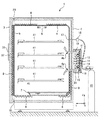
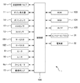
図1及び図2を参照しつつ、本実施の形態のインキュベータ1の構成例について説明する。図1は、インキュベータ1の一例の側面断面図である。図2は、図1のインキュベータ1の制御を司る構成の一例を示すブロック図である。尚、図1の例示では、X軸はインキュベータ1の横幅方向を示し、Y軸はインキュベータ1の奥行方向を示し、Z軸はインキュベータ1の高さ方向を示すものとする。
=== First embodiment ===
<<< Configuration of incubator >>
A configuration example of the
図1及び図2に例示されるように、インキュベータ1は、チャンバー4と、ファン6と、バイパス路10と、循環ポンプ15と、オゾン発生器11と、チャンバー4用のヒータ8と、バイパス路10用のヒータ16(バイパス路ヒータ)と、制御部100とを備えている。
As illustrated in FIGS. 1 and 2, the
チャンバー4は、その内部に培養室を形成する例えばステンレス製の略直方形状の箱であり、その奥行方向の前側の開口にはヒンジ(不図示)を介して開閉可能な内扉5が設けられている。内扉5は、例えば強化ガラス製の平板であり、チャンバー4の開口をパッキン(不図示)を介して閉じると、同チャンバー4の内部が外部に対し気密になるように構成されている。尚、図1に例示されるチャンバー4では、その横幅方向に対をなす内壁に対し、被培養体を載置するための例えばステンレス製の棚41が支持されている。また、チャンバー4は、例えば金属製で同チャンバー4と略相似形状をなす外箱2に収容されている。この外箱2の奥行方向の前側の開口にはヒンジ(不図示)を介して開閉可能な外扉3が設けられている。外扉3は、外箱2の開口をパッキン33を介して閉じると、同外箱2の内部が外部に対し気密になるように構成されている。
The
ファン6は、チャンバー4の例えば天井面の略中央部に設けられるシロッコファンである。培養時及び滅菌処理時の双方において、このファン6が一定方向に回転することにより、例えば、チャンバー4の略中央部において下側から上側へ空気の流れが生じる。これにより、チャンバー4の内部の空気が攪拌される。
The fan 6 is a sirocco fan that is provided in, for example, a substantially central portion of the ceiling surface of the
バイパス路10は、チャンバー4の奥行方向の後側の壁に形成された孔4aと孔4bとを同チャンバー4の外側で繋ぐ例えばステンレス製の管である。本実施の形態では、バイパス路10には、以下述べる循環ポンプ15及びオゾン発生器11の他に、CO2センサ12、O2(酸素)センサ13、オゾンセンサ14等が設けられている。また、本実施の形態では、バイパス路10は外箱2の壁を貫通して同壁の外側に露出しているが、この露出部分は箱21によって外部から保護されている。但し、このような構成に限定されるものではなく、バイパス路10は、例えば、チャンバー4の奥行方向の後側の壁と、外箱2の奥行方向の後側の壁との間にあってもよい。
The
循環ポンプ15は、バイパス路10の途中に設けられて、培養時及び滅菌処理時の双方において、チャンバー4の内部の空気を、例えば、孔4aを経由してチャンバー4の内側から外側へ導いた後、孔4bを経由してチャンバー4の外側から内側へ戻す(図1の白抜きの矢印参照)。
The
オゾン発生器11は、バイパス路10の途中に設けられており、滅菌処理時において、同バイパス路10の内部を流れる空気から例えば無声放電によってオゾンガスを発生する。オゾン発生器11で発生したオゾンガスは、孔4bを経由してチャンバー4の内部に流れ込むようになっている。尚、本実施の形態では、バイパス路10において、オゾン発生器11は、オゾンセンサ14よりも、空気の流れの下流側に設けられている。これにより、オゾンセンサ14は、チャンバー4の内部のオゾンガスの濃度をより正確に検出できる。
The
チャンバー4用のヒータ8は、チャンバー4の壁と外箱2の壁との間のエアジャケットにおいて、不図示の断熱材とともに、チャンバー4の外壁に熱的に接触するように設けられている。また、このチャンバー4用のヒータ8は、外扉3の内側にも設けられている。このように、内扉5で閉じられたチャンバー4が有する6つの面全てに対向するヒータ8によって、培養時及び滅菌処理時の双方において、チャンバー4の内部の温度を略均一に調節できる。
The
バイパス路10用のヒータ16は、箱21の内側に設けられて、特に滅菌処理時において、バイパス路10の内部の温度を調節するためのものである。
The
制御部100は、図2に例示されるように、前述した、オゾン発生器11、オゾンセンサ14、CO2センサ12、O2センサ13、ヒータ8、16、ファン6を駆動するファンモータ6a、及び循環ポンプ15を統括制御する。
As illustrated in FIG. 2, the
また、インキュベータ1は、以下述べる、流量制御バルブ18、サーミスタ101(第1温度センサ)、サーミスタ102(第2温度センサ)、ROM103、RAM104、タイマ105、コントロールパネル31、及び電気錠32を更に備えており、図2に例示されるように、制御部100は、これらを統括制御する。
The
流量制御バルブ18は、培養時において、チャンバー4の内部でCO2やO2等のガスの濃度を所定値に維持するために、チャンバー4の壁を貫通して設けられたノズル17を通じて供給されるガスの流量を制御するための電磁バルブである。この流量制御バルブ18は、インキュベータ1の外部に設置されたCO2やO2等のガスボンベ19と所定の配管を介して接続されている。チャンバー4の内部の空気を所定濃度のCO2ガス雰囲気に維持する場合、制御部100は、循環ポンプ15を駆動してチャンバー4の内部の空気をバイパス路10に導きつつ、同バイパス路10においてCO2センサ12により検出されるCO2ガスの濃度が所定値に維持されるように、流量制御バルブ18を制御するようになっている。或いは、チャンバー4の内部の空気を所定濃度のO2ガス雰囲気に維持する場合も、O2が充填されたガスボンベ19と、O2センサ13とを用いて、制御部100は、同様の制御を実行するようになっている。
The flow
サーミスタ101は、チャンバー4の内部の温度を検出するべく同チャンバー4の所定の位置に設けられている。
サーミスタ102は、バイパス路10の内部、好ましくはオゾン発生器11近傍の温度を検出するべく同バイパス路10の所定の位置に設けられている。
ROM103は、培養及び滅菌処理の双方において、制御部100の処理手順を定めるプログラム等を記憶し、RAM104は、同制御部100による処理の際に用いられるデータ等を記憶する。
タイマ105は、例えば滅菌処理の時間等を計時する。
The
The
The
The
コントロールパネル31は、例えば外扉3の正面に設けられており、チャンバー4の内部の温度やCO2又はO2ガスの濃度等を入力するためのキー(不図示)や、現在の温度や濃度等を表示するためのディスプレイ(不図示)等を有している。また、培養及び滅菌処理の開始及び停止も、このコントロールパネル31上の操作を通じて行なわれる。
The
電気錠32は、外扉3に設けられており、コントロールパネル31上の操作を通じて又は制御部100からの直接の命令によって、同外扉3が外箱2の開口を閉じた状態で電気的に施錠したり開錠したりする。
The
尚、インキュベータ1のチャンバー4の底面には、水を収納する水皿7が載置可能となっている。水皿7中の水は、培養時には、空気を所定の湿度に維持するとともに、滅菌処理時には、オゾンガスの滅菌作用を向上させる。つまり、培養時及び滅菌処理時の双方において、水皿7は、チャンバー4の内部の湿度を上昇させるためのものである。尚、オゾンガスは、乾燥した状態よりも、高湿度な状態にある方が、滅菌作用がより高いことが確認されている。
A water tray 7 for storing water can be placed on the bottom surface of the
<<<制御部の機能>>>
前述した制御部100は、滅菌処理運転において、ファン6、循環ポンプ15、及びオゾン発生器11を駆動しつつ、バイパス路10の内部の温度がチャンバー4の内部の温度より高くなるようにヒータ8、16を個別に駆動するようになっている。
<<< Control function >>>
In the sterilization operation, the
循環ポンプ15によってバイパス路10に導かれたチャンバー4の内部の空気は、オゾン発生器11でオゾンガスの原料となる。発生したオゾンガスは、空気とともに、バイパス路10からチャンバー4に戻る。この循環によって、チャンバー4の内部のオゾンガスの濃度は所定範囲に維持される。尚、ファン6、循環ポンプ15、及びオゾン発生器11は、タイマ105で計時される予め定められた時間だけ連続して運転されるが、これに限定されるものではない。例えば、タイマ105で計時される予め定められた時間において、オゾンセンサ14により検出されるオゾンガスの濃度が所定範囲に維持されるようにオゾン発生器11が断続的に運転されてもよい。
The air inside the
このように、オゾンガスの原料をチャンバー4の内部の空気に求めることによって、例えば外部からオゾンガスを供給することに伴う内部の高圧化を回避できるため、同チャンバー4を特に耐圧仕様としたり、或いはオゾン分解手段を伴った排気ラインを設けたりしなくても、外部にオゾンガスが漏れる心配はない。よって、チャンバー4の内部を確実に滅菌できる上に安全で低コストのインキュベータ1が提供される。また、循環ポンプ15が設けられたバイパス路10は、培養時におけるCO2やO2等のガスの濃度を検出する機能も兼ね備えることによって、例えば培養及び滅菌処理の双方のために循環ポンプを2台設ける必要がなくなるため、インキュベータ1がより一層低コストとなる。
Thus, by obtaining the ozone gas raw material from the air inside the
ヒータ8、16は、タイマ105で計時される予め定められた時間において、サーミスタ102によって検出されるバイパス路10の内部の温度が、サーミスタ101によって検出されるチャンバー4の内部の温度よりも所定の温度差をもって高くなるように、個別に制御される。但し、これに限定されるものではなく、ヒータ8、16は、例えば、バイパス路10及びチャンバー4の間に所定の温度差が生じるように予め定められた電流をもって、タイマ105で計時される予め定められた時間だけ連続して運転されてもよい。
In the
一般に、チャンバー4の内部の湿度は、例えば外部の大気に比べて高いため、このような高湿度の空気がバイパス路10に導かれてオゾン発生器11でもし結露した場合、これは、オゾンガスの発生効率を低下させるだけでなく、同オゾン発生器11の故障の原因となる。しかし、本実施の形態のインキュベータ1では、ヒータ8、16の制御によって、バイパス路10の内部がチャンバー4の内部よりも高温に維持されているため、チャンバー4の内部の空気がバイパス路10の内部において結露する事態が抑制される。
In general, since the humidity inside the
また、前述した制御部100は、滅菌処理運転を終了すると、オゾンセンサ14により検出されるオゾンガスの濃度を参照し、オゾンガスの濃度が予め定められた所定値以上であると判断している間は電気錠32の施錠を維持し、オゾンガスの濃度が所定値未満であると判断した時点で開錠する。尚、この所定値は、例えば、オゾンガスが人体にとって無害とされるような同ガスの空気中の許容濃度である。但し、これに限定されるものではなく、例えば、制御部100は、滅菌処理運転を終了すると、例えばタイマ105で計時される予め定められた時間だけ電気錠32の施錠を維持した後に開錠してもよい。空気中のオゾンガスが自然に分解する速度は周知であるため、滅菌処理運転の終了から電気錠32の開錠までの時間は、この自然分解速度に基づいて設定すればよい。
Further, when the
これにより、少なくとも外箱2の外部に有害なオゾンガスが漏れる事態はより確実に防止される。また、電気錠32の施錠により外扉3は確実に外箱2の開口を閉じているため、例えばチャンバー4の内扉5を開錠した状態にして、滅菌処理を行うことにより、内扉5及びチャンバー4の接触部分のパッキン(不図示)等も滅菌できる。
Thereby, the situation where harmful ozone gas leaks at least outside the
===第2の実施の形態===
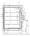
図3を参照しつつ、本実施の形態のインキュベータ1’の構成例について説明する。同図は、インキュベータ1’の一例の側面断面図である。尚、同図の例示では、X軸はインキュベータ1’の横幅方向を示し、Y軸はインキュベータ1’の奥行方向を示し、Z軸はインキュベータ1’の高さ方向を示すものとする。また、同図に例示される構成のうち、前述した図1に例示される構成と略同一の構成には同一の番号が付されている。
=== Second embodiment ===
A configuration example of the
インキュベータ1’は、チャンバー4と、ファン6と、バイパス路10’と、オゾン発生器11と、チャンバー4用のヒータ8と、バイパス路10’用のヒータ16(バイパス路ヒータ)と、オゾンセンサ14と、図2の例示と略同一のサーミスタ101(第1温度センサ)、サーミスタ102(第2温度センサ)、及び制御部100とを備えている。
The
図3の例示における図1の例示との主な相違点は、バイパス路10’がチャンバー4の内部に形成されていることと、ファン6が同バイパス路10’の内部に設けられて空気の流路を形成することと、これにより前述した循環ポンプ15を備えていないこととである。以下、図3の例示について、図1の例示との相違点を中心に説明し、共通点に関する説明を省略する。
The main difference between the example of FIG. 3 and the example of FIG. 1 is that the
バイパス路10’は、チャンバー4の例えば奥行方向の後側の壁と、同チャンバー4の内部にあって同壁と対向する例えばステンレス製の壁板9との間に形成されている。この構成により、チャンバー4の内部は、棚41が配置されている培養室と、バイパス路10’とに分けられる。本実施の形態では、バイパス路10’には、ファン6、オゾンセンサ14、O2センサ13、CO2センサ12、オゾン発生器11等が設けられている。また、本実施の形態では、オゾンセンサ14、O2センサ13、CO2センサ12、及びオゾン発生器11のそれぞれにおける配線側(ヘッドと反対側)部分は、外箱2の壁を貫通して同壁の外側に露出しているが、この露出部分は箱21によって外部から保護されている。但し、このような構成に限定されるものではなく、配線側部分は、例えば、チャンバー4の奥行方向の後側の壁と、外箱2の奥行方向の後側の壁との間にあってもよい。
The
ファン6は、バイパス路10’の上側に設けられるシロッコファンである。培養時及び滅菌処理時において、このファン6が一定方向に回転することにより、例えば、培養室側には下側から上側へ空気の流れが生じるとともに、バイパス路10’の上側から下側へ空気の流れが生じる(図3の白抜きの矢印参照)。このファン6の回転によって壁板9の孔9aを通じてバイパス路10’に流れた培養室側の空気は、オゾン発生器11でオゾンガスの原料となる。発生したオゾンガスは、空気とともに、バイパス路10’から培養室側に流れる。この循環によって、チャンバー4の内部の空気が攪拌されて、培養室側のオゾンガスの濃度は所定範囲に維持される。
The fan 6 is a sirocco fan provided on the upper side of the bypass passage 10 '. When the fan 6 rotates in a fixed direction during culture and sterilization, for example, air flows from the lower side to the upper side on the culture chamber side, and air flows from the upper side to the lower side of the bypass passage 10 '. (See the white arrow in FIG. 3). The culture chamber side air that has flowed into the
このインキュベータ1’は、前述したインキュベータ1と同様に、チャンバー4の内部を確実に滅菌できる上に安全で低コストである。
This
===その他の実施の形態===
前述した実施の形態は、本発明の理解を容易にするためのものであり、本発明を限定して解釈するためのものではない。本発明はその趣旨を逸脱することなく変更や改良等が可能であり、また本発明はその等価物も含むものである。
=== Other Embodiments ===
The above-described embodiments are intended to facilitate understanding of the present invention, and are not intended to limit the present invention. The present invention can be changed and improved without departing from the gist thereof, and the present invention includes equivalents thereof.
前述した実施の形態では、バイパス路10、10’は、チャンバー4の奥行方向の後側に設けられていたが、これに限定されるものではない。バイパス路10、10’は、要するに、チャンバー4の外部又は内部にあって同チャンバー4と併設されていれば、何れの側に設けられていてもよい。
In the above-described embodiment, the
また、前述した実施の形態では、チャンバー4の内部と、バイパス路10、10’の内部との温度差をヒータ8、16によって形成していたが、これに限定されるものではない。要するに、このような温度差を形成できる加熱手段であれば、如何なる手段を用いてもよい。
In the above-described embodiment, the temperature difference between the inside of the
また、前述した実施の形態では、電気錠32は、外扉3に設けられていたが、これに限定されるものではなく、例えば内扉5に設けられていてもよい。
In the embodiment described above, the
また、前述した実施の形態では、滅菌処理にオゾンガスが用いられていたが、これに限定されるものではなく、例えば過酸化水素(H2O2)ガス等であってもよい。 In the embodiment described above, ozone gas is used for sterilization, but the present invention is not limited to this. For example, hydrogen peroxide (H 2 O 2 ) gas or the like may be used.
1、1’ インキュベータ 2 外箱 3 外扉
4 チャンバー 4a、4b 孔 5 内扉
6 ファン 6a ファンモータ 7 水皿
8、16 ヒータ 9 壁板 9a 孔
10、10’ バイパス路 11 オゾン発生器 12 CO2センサ
13 O2センサ 14 オゾンセンサ 15 循環ポンプ
17 ノズル 18 流量制御バルブ 19 ガスボンベ
21 箱 31 コントロールパネル 32 電気錠
33 パッキン 41 棚 100 制御部
101、102 サーミスタ 103 ROM 104 RAM
105 タイマ
DESCRIPTION OF
105 timer
Claims (3)
前記チャンバー内の空気が循環するバイパス路を当該チャンバーと併設して設け、
前記チャンバー内の空気を攪拌するファンと、
オゾン発生器と、
前記バイパス路に設けられ、前記バイパス路内のオゾン濃度を測るオゾンセンサと、
前記チャンバー内を加熱するヒータとは別に設けられ、前記バイパス路を加熱するためのバイパス路ヒータと、
前記チャンバー内の温度を測る第1温度センサと、
前記バイパス路内の温度を測る第2温度センサと、
制御部とを備え、
前記制御部は、前記チャンバー内を減菌処理する際、前記オゾンセンサの検出値に基づいて前記オゾン発生器を制御して前記チャンバー内のオゾン濃度を所定の範囲に制御するとともに、前記第1温度センサ及び前記第2温度センサの検出値に基づいて前記バイパス路内及び前記オゾン発生器内の温度を前記チャンバー内の温度より高くなるように前記バイパス路ヒータを制御することを特徴とするCO2インキュベータ。 A chamber for storing the culture object and a door for taking the culture object in and out of the chamber are provided, and the supply to the chamber is performed based on the detection value of the CO 2 sensor for detecting the CO 2 gas concentration in the chamber. in CO 2 incubator comprising controlling the amount of CO 2 gas,
A bypass path through which air in the chamber circulates is provided along with the chamber,
A fan for stirring the air in the chamber;
An ozone generator;
An ozone sensor that is provided in the bypass and measures the ozone concentration in the bypass;
Provided separately from the heater for heating the inside of the chamber, a bypass passage heater for heating the bypass passage;
A first temperature sensor for measuring the temperature in the chamber;
A second temperature sensor for measuring the temperature in the bypass path;
A control unit,
The control unit controls the ozone generator based on a detection value of the ozone sensor to control the ozone concentration in the chamber to a predetermined range when the inside of the chamber is sterilized. The bypass path heater is controlled based on detection values of the temperature sensor and the second temperature sensor so that the temperature in the bypass path and the ozone generator is higher than the temperature in the chamber. 2 incubators.
Priority Applications (1)
| Application Number | Priority Date | Filing Date | Title |
|---|---|---|---|
| JP2008334357A JP2010154792A (en) | 2008-12-26 | 2008-12-26 | Co2 incubator |
Applications Claiming Priority (1)
| Application Number | Priority Date | Filing Date | Title |
|---|---|---|---|
| JP2008334357A JP2010154792A (en) | 2008-12-26 | 2008-12-26 | Co2 incubator |
Publications (1)
| Publication Number | Publication Date |
|---|---|
| JP2010154792A true JP2010154792A (en) | 2010-07-15 |
Family
ID=42573190
Family Applications (1)
| Application Number | Title | Priority Date | Filing Date |
|---|---|---|---|
| JP2008334357A Pending JP2010154792A (en) | 2008-12-26 | 2008-12-26 | Co2 incubator |
Country Status (1)
| Country | Link |
|---|---|
| JP (1) | JP2010154792A (en) |
Cited By (14)
| Publication number | Priority date | Publication date | Assignee | Title |
|---|---|---|---|---|
| JP2012037176A (en) * | 2010-08-10 | 2012-02-23 | Osaka Gas Co Ltd | Ventilation system |
| JP2012075373A (en) * | 2010-09-30 | 2012-04-19 | Sanyo Electric Co Ltd | Incubator |
| WO2012173076A3 (en) * | 2011-06-14 | 2013-02-07 | ローツェ株式会社 | Sensor unit, and constant-temperature device using sensor unit |
| WO2015053386A1 (en) | 2013-10-11 | 2015-04-16 | パナソニック ヘルスケアホールディングス株式会社 | Culture apparatus |
| CN105532314A (en) * | 2016-01-11 | 2016-05-04 | 中国农业科学院作物科学研究所 | Low-concentration carbon dioxide incubator for basic scientific research and control method |
| JP2017079642A (en) * | 2015-10-28 | 2017-05-18 | 八洲電業株式会社 | Culture system, and method for using culture system |
| WO2017169850A1 (en) * | 2016-03-28 | 2017-10-05 | パナソニックヘルスケアホールディングス株式会社 | Culture apparatus, and method for controlling culture apparatus |
| JP2017175945A (en) * | 2016-03-28 | 2017-10-05 | パナソニックヘルスケアホールディングス株式会社 | Culture apparatus |
| CN107922904A (en) * | 2015-03-31 | 2018-04-17 | 兴盛生物科技股份有限公司 | For being produced from the cell retainer of somatic therapy |
| CN108369172A (en) * | 2015-12-28 | 2018-08-03 | 普和希控股公司 | Measuring fine particles instrument and cleaning ambient equipment in gas |
| CN113322183A (en) * | 2021-06-03 | 2021-08-31 | 杭州捷诺飞生物科技股份有限公司 | Carbon dioxide incubator |
| CN117603783A (en) * | 2023-11-28 | 2024-02-27 | 烟台市蓬莱区疾病预防控制中心 | A multifunctional microbial incubator for microbial detection |
| US12098358B2 (en) | 2015-03-31 | 2024-09-24 | Thrive Bioscience, Inc. | Automated incubator with robotic transport |
| US12180454B2 (en) | 2015-03-31 | 2024-12-31 | Thrive Bioscience, Inc. | Automated cell culture incubator |
-
2008
- 2008-12-26 JP JP2008334357A patent/JP2010154792A/en active Pending
Cited By (27)
| Publication number | Priority date | Publication date | Assignee | Title |
|---|---|---|---|---|
| JP2012037176A (en) * | 2010-08-10 | 2012-02-23 | Osaka Gas Co Ltd | Ventilation system |
| US8563300B2 (en) | 2010-09-30 | 2013-10-22 | Panasonic Healthcare Co., Ltd. | Incubator |
| JP2012075373A (en) * | 2010-09-30 | 2012-04-19 | Sanyo Electric Co Ltd | Incubator |
| CN103597067A (en) * | 2011-06-14 | 2014-02-19 | 日商乐华股份有限公司 | Sensor unit, and constant-temperature device using sensor unit |
| JPWO2012173076A1 (en) * | 2011-06-14 | 2015-02-23 | ローツェ株式会社 | Sensor unit and thermostat using the sensor unit |
| US9464266B2 (en) | 2011-06-14 | 2016-10-11 | Rorze Corporation | Sensor unit and constant-temperature device |
| WO2012173076A3 (en) * | 2011-06-14 | 2013-02-07 | ローツェ株式会社 | Sensor unit, and constant-temperature device using sensor unit |
| WO2015053386A1 (en) | 2013-10-11 | 2015-04-16 | パナソニック ヘルスケアホールディングス株式会社 | Culture apparatus |
| EP3031901A4 (en) * | 2013-10-11 | 2016-08-24 | Panasonic Healthcare Holdings Co Ltd | Culture apparatus |
| US10023834B2 (en) | 2013-10-11 | 2018-07-17 | Phc Holdings Corporation | Culture apparatus |
| US12180454B2 (en) | 2015-03-31 | 2024-12-31 | Thrive Bioscience, Inc. | Automated cell culture incubator |
| US11879120B2 (en) | 2015-03-31 | 2024-01-23 | Thrive Bioscience, Inc. | Cell maintainer for autologous cell therapy production |
| US11168297B2 (en) * | 2015-03-31 | 2021-11-09 | Thrive Bioscience, Inc. | Cell maintainer for autologous cell therapy production |
| US12359159B2 (en) | 2015-03-31 | 2025-07-15 | Thrive Bioscience, Inc. | Cell culture incubators with integrated cell manipulation systems |
| CN107922904A (en) * | 2015-03-31 | 2018-04-17 | 兴盛生物科技股份有限公司 | For being produced from the cell retainer of somatic therapy |
| US12098358B2 (en) | 2015-03-31 | 2024-09-24 | Thrive Bioscience, Inc. | Automated incubator with robotic transport |
| JP2017079642A (en) * | 2015-10-28 | 2017-05-18 | 八洲電業株式会社 | Culture system, and method for using culture system |
| EP3372984A4 (en) * | 2015-12-28 | 2018-12-26 | PHC Holdings Corporation | Gas-borne fine particle measuring instrument and clean environmental device |
| CN108369172A (en) * | 2015-12-28 | 2018-08-03 | 普和希控股公司 | Measuring fine particles instrument and cleaning ambient equipment in gas |
| CN105532314A (en) * | 2016-01-11 | 2016-05-04 | 中国农业科学院作物科学研究所 | Low-concentration carbon dioxide incubator for basic scientific research and control method |
| JP2017175945A (en) * | 2016-03-28 | 2017-10-05 | パナソニックヘルスケアホールディングス株式会社 | Culture apparatus |
| US11098277B2 (en) | 2016-03-28 | 2021-08-24 | Phc Holdings Corporation | Culture apparatus and method of controlling culture apparatus |
| EP3418372B1 (en) | 2016-03-28 | 2020-01-01 | PHC Holdings Corporation | Culture apparatus, and method for controlling culture apparatus |
| JPWO2017169850A1 (en) * | 2016-03-28 | 2018-09-06 | Phcホールディングス株式会社 | CULTURE DEVICE AND CULTURE DEVICE CONTROL METHOD |
| WO2017169850A1 (en) * | 2016-03-28 | 2017-10-05 | パナソニックヘルスケアホールディングス株式会社 | Culture apparatus, and method for controlling culture apparatus |
| CN113322183A (en) * | 2021-06-03 | 2021-08-31 | 杭州捷诺飞生物科技股份有限公司 | Carbon dioxide incubator |
| CN117603783A (en) * | 2023-11-28 | 2024-02-27 | 烟台市蓬莱区疾病预防控制中心 | A multifunctional microbial incubator for microbial detection |
Similar Documents
| Publication | Publication Date | Title |
|---|---|---|
| JP2010154792A (en) | Co2 incubator | |
| JP5416965B2 (en) | CO2 incubator | |
| KR101357336B1 (en) | Culture apparatus | |
| JP5727187B2 (en) | incubator | |
| US8216830B2 (en) | Culture apparatus | |
| JP3670876B2 (en) | Incubator | |
| EP1992684B1 (en) | Incubator for isolator | |
| JP6616886B2 (en) | Incubator | |
| US8227239B2 (en) | Culture apparatus | |
| WO2021220784A1 (en) | Incubator | |
| EP2210618B1 (en) | Isolator | |
| JP5624711B2 (en) | Incubator | |
| JP4773986B2 (en) | Ozone gas sterilizer | |
| JP2004267064A (en) | CO2 incubator | |
| KR101765048B1 (en) | high temperature air supply device of sterilant sterilizer | |
| US7544325B2 (en) | BIER vessel high-speed biological indicator shuttling system | |
| JP7793037B2 (en) | Culture device and culture system | |
| JP4344702B2 (en) | Incubator | |
| CN117516135A (en) | Drying device and cleaning machine | |
| JP2008029987A (en) | Waste treatment apparatus and waste treatment method |