JP2010146977A - Fuel battery, fuel battery cell, and constituting member unit of the same - Google Patents
Fuel battery, fuel battery cell, and constituting member unit of the same Download PDFInfo
- Publication number
- JP2010146977A JP2010146977A JP2008326012A JP2008326012A JP2010146977A JP 2010146977 A JP2010146977 A JP 2010146977A JP 2008326012 A JP2008326012 A JP 2008326012A JP 2008326012 A JP2008326012 A JP 2008326012A JP 2010146977 A JP2010146977 A JP 2010146977A
- Authority
- JP
- Japan
- Prior art keywords
- gas
- gas permeable
- layer
- fuel cell
- thickness
- Prior art date
- Legal status (The legal status is an assumption and is not a legal conclusion. Google has not performed a legal analysis and makes no representation as to the accuracy of the status listed.)
- Withdrawn
Links
Images

Classifications
-
- Y—GENERAL TAGGING OF NEW TECHNOLOGICAL DEVELOPMENTS; GENERAL TAGGING OF CROSS-SECTIONAL TECHNOLOGIES SPANNING OVER SEVERAL SECTIONS OF THE IPC; TECHNICAL SUBJECTS COVERED BY FORMER USPC CROSS-REFERENCE ART COLLECTIONS [XRACs] AND DIGESTS
- Y02—TECHNOLOGIES OR APPLICATIONS FOR MITIGATION OR ADAPTATION AGAINST CLIMATE CHANGE
- Y02E—REDUCTION OF GREENHOUSE GAS [GHG] EMISSIONS, RELATED TO ENERGY GENERATION, TRANSMISSION OR DISTRIBUTION
- Y02E60/00—Enabling technologies; Technologies with a potential or indirect contribution to GHG emissions mitigation
- Y02E60/30—Hydrogen technology
- Y02E60/50—Fuel cells
Landscapes
- Fuel Cell (AREA)
Abstract
【課題】注入された樹脂の樹脂圧に対して電解質膜の端部が持ち上げられてガスケットの端面に臨み、これがガスのクロスリーク路を形成して燃料電池のクロスリーク耐久を低下させるという課題が解消され、かつ、ガス透過層同士の接触による短絡も生じ得ない燃料電池セルの構成部材ユニットと、該ユニットからなる燃料電池セル、該燃料電池セルが積層されてなる燃料電池を提供する。
【解決手段】燃料電池セルの構成部材ユニットにおいて、2つのガス透過層(ガス流路層6A,6)はいずれも電解質膜1よりも側方に張り出しており、2つのガス透過層6Aの側方に張り出した箇所62の厚み:t2は、ガス透過層6Aの他の箇所の厚み:t1に対して変化しており(厚くなっており)、これが、2つのガス透過層6A,6の側方に張り出した箇所同士の接触防止手段となっている。
【選択図】図1The problem is that the end of the electrolyte membrane is lifted against the resin pressure of the injected resin and faces the end face of the gasket, which forms a gas cross leak path and reduces the cross leak durability of the fuel cell. There are provided a constituent unit of a fuel battery cell which is eliminated and a short circuit due to contact between gas permeable layers cannot occur, a fuel battery cell comprising the unit, and a fuel battery in which the fuel battery cells are laminated.
In a constituent unit of a fuel battery cell, two gas permeable layers (gas flow path layers 6A, 6) both project laterally from an electrolyte membrane 1, and the two gas permeable layers 6A side. The thickness t2 of the portion 62 projecting toward the side changes (becomes thick) with respect to the thickness t1 of the other portion of the gas permeable layer 6A: this is the side of the two gas permeable layers 6A and 6 This is a means for preventing contact between the overhanging portions.
[Selection] Figure 1
Description
本発明は、燃料電池セルの構成部材ユニットと、該構成部材ユニットからなる燃料電池セル、この燃料電池セルが積層されてなる燃料電池に関するものである。 The present invention relates to a component unit of a fuel cell, a fuel cell comprising the component unit, and a fuel cell in which the fuel cells are stacked.
固体高分子型燃料電池の燃料電池セルは、イオン透過性の電解質膜と、該電解質膜を挟持するアノード側およびカソード側の触媒層とから膜電極接合体(MEA:Membrane Electrode Assembly)が形成され、たとえば、このMEAとこれを挟持するアノード側およびカソード側のガス拡散層(GDL)とから電極体(MEGA:Membrane Electrode & Gas Diffusion Layer Assembly)が形成され、電極体に燃料ガスもしくは酸化剤ガスを提供するとともに電気化学反応によって生じた電気を集電するための金属多孔体からなるガス流路層とセパレータが電極体の両側に配されて構成されている。なお、セパレータにガス流路溝が形成された燃料電池セルも従来一般のものであり、この形態の場合にはガス流路層となる金属多孔体は不要である。実際の燃料電池スタックは、所要電力に応じた基数の燃料電池セルが積層され、スタッキングされることによって形成されている。 A fuel cell of a polymer electrolyte fuel cell has a membrane electrode assembly (MEA) formed from an ion-permeable electrolyte membrane and an anode-side and cathode-side catalyst layer sandwiching the electrolyte membrane. For example, an electrode body (MEGA: MEMBRANE ELECTRODE & GAS DIFFUSION LAYER ASSEMBLY) is formed from the MEA and the anode-side and cathode-side gas diffusion layers (GDL) sandwiching the MEA, and a fuel gas or an oxidant gas is formed in the electrode body. And a gas flow path layer made of a metal porous body for collecting electricity generated by an electrochemical reaction and a separator are arranged on both sides of the electrode body. In addition, the fuel cell in which the gas flow channel groove is formed in the separator is also a conventional one, and in this case, the metal porous body that becomes the gas flow channel layer is unnecessary. An actual fuel cell stack is formed by stacking and stacking a number of fuel cell cells according to required power.
上記構成の燃料電池セルにおいては、膜電極接合体に供給される燃料ガスや酸化剤ガス、さらにはセルの昇温を抑止するための冷却水などの流体をシールするためのガスケットが電極体および金属多孔体の周縁に形成されている。このガスケットは燃料電池セルごとに形成されており、電極体および金属多孔体の周縁にガスケットを有した燃料電池セルを所定の基数だけ積層した後にスタッキングがおこなわれている。このガスケットの成形は一般に射出成形や圧縮成形にておこなわれている。たとえば射出成形の場合を取り上げると、成形型のキャビティ内にセパレータを収容し、次いでガス流路となるアノード側もしくはカソード側の一方の金属多孔体を収容し、次いで電極体もしくは膜電極接合体を収容し、次いでアノード側もしくはカソード側の他方の金属多孔体を収容した姿勢で、電極体および金属多孔体の周縁のガスケット成形用キャビティに樹脂を注入するものである。 In the fuel cell having the above-described configuration, a gasket for sealing a fluid such as a fuel gas and an oxidant gas supplied to the membrane electrode assembly, and a cooling water for suppressing a temperature rise of the cell, It is formed at the periphery of the metal porous body. This gasket is formed for each fuel cell, and stacking is performed after stacking a predetermined number of fuel cells each having a gasket on the periphery of the electrode body and the porous metal body. This gasket is generally formed by injection molding or compression molding. For example, in the case of injection molding, a separator is accommodated in a cavity of a molding die, and then either a metal porous body on the anode side or cathode side that becomes a gas flow path is accommodated, and then an electrode body or a membrane electrode assembly is mounted. The resin is then injected into the gasket forming cavity at the periphery of the electrode body and the metal porous body in a posture in which the other metal porous body on the anode side or the cathode side is housed.
上記するセパレータは、たとえばチタンやステンレスからなる2枚のプレートの間に流路が形成されたプレートが介層された3層構造のものや、中間層を樹脂製の枠材とし、2枚のプレートの一方から多数のディンプルや流路を画成するリブを突出させて冷却水流路を形成するものなどがある。この3層構造のセパレータは、当該セル自体のアノード側もしくはカソード側のいずれか一方のセパレータであると同時に、積層姿勢において隣接するセルのアノード側もしくはカソード側の他方のセパレータとなるものである。すなわち、この3層構造セパレータを有する燃料電池セルのセル構成部材は、一つの3層構造セパレータと、アノード側およびカソード側の金属多孔体(ガス流路層)と、膜電極接合体もしくは電極体と、からなり、複数の燃料電池セルが積層された姿勢において、任意の燃料電池セルは、その両端にアノード側およびカソード側のセパレータを有することとなる。 The separator described above has a three-layer structure in which a plate in which a flow path is formed between two plates made of titanium or stainless steel, for example, or an intermediate layer made of a resin frame material. There are a plurality of dimples and ribs that define a flow path project from one side of the plate to form a cooling water flow path. The separator having the three-layer structure is either the anode side or the cathode side separator of the cell itself, and at the same time, is the other separator on the anode side or the cathode side of the adjacent cell in the stacked posture. That is, the cell constituent member of the fuel cell having this three-layer structure separator includes one three-layer structure separator, a metal porous body (gas channel layer) on the anode side and the cathode side, and a membrane electrode assembly or electrode body. In a posture in which a plurality of fuel cells are stacked, an arbitrary fuel cell has anode-side and cathode-side separators at both ends thereof.
ところで、ガス拡散層やガス流路層といったガス透過層や触媒層に比して電解質膜の端部は側方に張り出しており、ガスケットが成形された際の姿勢においては、電解質膜の張り出し端部がガスケットの内部に埋め込まれた構造を呈するのが一般的である。このような構造を適用する理由として、その一つは、両極のガス拡散層や金属多孔体(ガス流路層)が接触して短絡するのを防止することである。また、他の理由は、一方の極(たとえばカソード極)から他方の極(たとえばアノード極)へ電解質膜の側端をガスが回り込んでクロスリークするのを防止するために、ある程度の張り出し長さを確保し、この張り出し部をガスケット内に埋設させた構造を適用しているというものである。 By the way, the end portion of the electrolyte membrane projects sideways as compared with the gas permeable layer such as the gas diffusion layer and the gas flow path layer and the catalyst layer, and the projecting end of the electrolyte membrane is in the posture when the gasket is formed. Generally, the portion has a structure embedded in the gasket. One of the reasons for applying such a structure is to prevent a short circuit due to contact between the gas diffusion layers and the metal porous body (gas flow path layer) of both electrodes. Another reason is that a certain length of overhang is required in order to prevent gas from flowing around the side edge of the electrolyte membrane from one electrode (for example, cathode electrode) to the other electrode (for example, anode electrode) and cross-leakage. The structure in which the overhang is embedded in the gasket is applied.
たとえば、成形型内に一つの3層構造セパレータと、金属多孔体とガス拡散層と膜電極接合体を収容して型閉めし、膜電極接合体の側方に画成されたガスケット用のキャビティ内に樹脂を注入してガスケットを成形する場合において、成形型内で膜電極接合体側に流れてきた樹脂の圧力により、側方に張り出した電解質膜の端部が上方に持ち上げられ、これがガスのクロスリーク路を形成してクロスリーク耐久を低下させるという課題が生じていた。 For example, a three-layer structure separator, a metal porous body, a gas diffusion layer, and a membrane electrode assembly are accommodated in a mold and the mold is closed, and a cavity for a gasket defined on the side of the membrane electrode assembly In the case of molding a gasket by injecting resin into the inside, the end of the electrolyte membrane protruding to the side is lifted upward by the pressure of the resin flowing to the membrane electrode assembly side in the mold, and this is There has been a problem that a cross leak path is formed to reduce the cross leak durability.
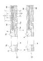
これを図7とその一部を拡大した図8に基づいて説明する。図7は、固定型S1と可動型S2のキャビティ内に電極体eとガス流路層となる金属多孔体f1、f2、および一つの3層構造セパレータgが収容され、ガスケット用の樹脂が注入されている状況を説明したものである。まず、電解質膜aとこれを挟持するカソード側およびアノード側の触媒層b1、b2とから膜電極接合体cが形成され、この膜電極接合体cをカソード側およびアノード側のガス拡散層d1、d2が挟持して電極体eが形成されたものを用意する。なお、各部材を成形型内へ収容するに際して、膜電極接合体とガス拡散層が予め一体に形成されていてもよいし、双方が分離されていて、それぞれを順に成形型内に収容するものであってもよい。ここで、電解質膜aの端部a1は電極体eの側方に張り出している。また、セパレータgは、2枚のステンレス製もしくはチタン製のプレートg1、g2と、このプレート間に介在してガスや冷却水などの流体用の流路を画成する中間層g3と、から構成されており、成形型内に、セパレータg、金属多孔体f2、電極体e、金属多孔体f1が積層姿勢を成した状態で型閉めされる。なお、この収容された構成部材のユニットで一つの燃料電池セルが形成されるものである。なお、この3層構造のセパレータgは、それが組み込まれる燃料電池セルのアノード側の金属多孔体f2に燃料ガス(流れ方向Z1)を提供するためのガス流通孔g3aと、セルが積層された姿勢において隣接するセルのカソード側の多孔体に酸化剤ガス(流れ方向Z2)を提供するためのガス流通孔g3bを備えている。 This will be described with reference to FIG. 7 and FIG. FIG. 7 shows that the electrode body e, the metal porous bodies f1 and f2 serving as a gas flow path layer, and one three-layer structure separator g are accommodated in the cavities of the fixed mold S1 and the movable mold S2, and the resin for the gasket is injected. It explains the situation that has been done. First, a membrane electrode assembly c is formed from the electrolyte membrane a and the cathode and anode catalyst layers b1 and b2 sandwiching the electrolyte membrane a, and the membrane electrode assembly c is formed into the cathode and anode gas diffusion layers d1, A member in which d2 is sandwiched and an electrode body e is formed is prepared. When each member is accommodated in the mold, the membrane electrode assembly and the gas diffusion layer may be formed integrally in advance, or both are separated, and each is accommodated in the mold in order. It may be. Here, the end a1 of the electrolyte membrane a protrudes to the side of the electrode body e. The separator g is composed of two stainless steel or titanium plates g1 and g2 and an intermediate layer g3 which is interposed between the plates and defines a flow path for fluid such as gas or cooling water. In the mold, the separator g, the porous metal body f2, the electrode body e, and the porous metal body f1 are closed in a stacked state. In addition, one fuel cell is formed by the unit of the accommodated component member. The separator g having a three-layer structure is formed by stacking cells with gas flow holes g3a for providing fuel gas (flow direction Z1) to the metal porous body f2 on the anode side of the fuel cell in which the separator is incorporated. A gas flow hole g3b is provided for providing an oxidant gas (flow direction Z2) to the porous body on the cathode side of an adjacent cell in the posture.
型閉めの後に、注入孔Hを介してガスケット成形用のキャビティC内に樹脂が注入される(Y方向)。樹脂が注入されると、キャビティC内で水平方向に張り出した電解質膜aの端部a1には、図8で示すようにその樹脂圧が作用し、該端部a1は上方に持ち上げられてキャビティCの上面に当接する。 After closing the mold, resin is injected into the gasket forming cavity C through the injection hole H (Y direction). When the resin is injected, the resin pressure acts on the end a1 of the electrolyte membrane a projecting in the horizontal direction in the cavity C as shown in FIG. 8, and the end a1 is lifted upward to form the cavity. Abuts on the upper surface of C.
この姿勢でガスケットが成形されて燃料電池セルが製造されると、電解質膜aはその端部a1がガスケットの上面に臨んだ状態となってしまう(端部a1が外部に臨む)。このような燃料電池セルを所定の基数だけ接着させることなく積み重ね、スタッキングすることにより、従来の燃料電池は形成されている。燃料電池セル同士を密着させないことにより、たとえば発電不良となった燃料電池セルを抜き出して他の燃料電池セルと入れ替えるといったメンテナンスが可能となる。したがって、一つの燃料電池セルに着目した際に、その構成部材であるアノード側およびカソード側の金属多孔体の一方には3層構造のセパレータがガスケットの射出成形の際に接着しており、他方の金属多孔体には積層姿勢において隣接する燃料電池セルのセパレータが接着されることなく当接した状態となっている。 When the gasket is molded in this posture and the fuel cell is manufactured, the electrolyte membrane a is in a state where the end a1 faces the upper surface of the gasket (the end a1 faces the outside). Conventional fuel cells are formed by stacking and stacking such fuel cells without adhering a predetermined number of bases. By not bringing the fuel cells into close contact with each other, it is possible to perform maintenance such as extracting a fuel cell that has failed in power generation and replacing it with another fuel cell. Accordingly, when focusing on one fuel cell, a separator having a three-layer structure is adhered to one of the anode side and cathode side metal porous bodies, which are constituent members, during gasket injection molding, The separator of the adjacent fuel battery cell is in contact with the metal porous body without being bonded in the stacked posture.
燃料電池セル同士が接着されることなく積み重ねられているのみの構造であるため、上記するようにそのメンテナンスは可能となる一方で、当該燃料電池セルと隣接セルのセパレータとの間に外部に連通する隙間が生じることは避けられない。それに加えて、上記のごとく電解質膜の端部が外部に臨んだ状態となっていることから、電解質膜が外部に通じる状態が形成されることとなり、このことは、ガスのクロスリーク路が形成されることを意味するものであり、燃料電池のクロスリーク耐久低下の一因となるものである。 Since the fuel cells are simply stacked without being bonded to each other, the maintenance can be performed as described above, while the fuel cells and the separators of the adjacent cells communicate with the outside. It is inevitable that a gap is generated. In addition, since the end portion of the electrolyte membrane faces the outside as described above, a state in which the electrolyte membrane communicates with the outside is formed, which means that a gas cross leak path is formed. This is a cause of a decrease in the cross leak durability of the fuel cell.
そこで、ガス流路層となる2つの金属多孔体を電解質膜よりも側方に張り出させ、電解質膜の端部が外部に臨まないようにする技術も発案されている。これを図8に対応する態様で示した図9を参照して説明すると、電解質膜aの上下に位置する金属多孔体f1’、f2’の双方が該電解質膜aよりも側方に張り出した構造である。 In view of this, a technique has been devised in which two metal porous bodies serving as gas flow path layers are projected laterally from the electrolyte membrane so that the end portions of the electrolyte membrane do not face the outside. This will be described with reference to FIG. 9 shown in an embodiment corresponding to FIG. 8. Both the porous metal bodies f1 ′ and f2 ′ positioned above and below the electrolyte membrane a protruded laterally from the electrolyte membrane a. Structure.
しかし、図7,8で示すセル構造と図9で示すセル構造を比較するとより明瞭となるが、図9で示すセル構造においては、双方の金属多孔体が電解質膜よりも側方に張り出したことにより、双方の間に何等の絶縁部材も介在しなくなる(図7,8では金属多孔体f1、f2間に電解質膜aが存在している)。したがって、何らかの外的要因、たとえば射出成形時の樹脂圧等によって一方の金属多孔体が他方の金属多孔体側へ変形した際(図中の一点鎖線図)には、たとえばそれらの端部同士が接触してしまい、ここで短絡が生じる可能性がある。そこで、たとえば特許文献1で開示するように、一方の金属多孔体の他方の金属多孔体側の端面に絶縁層を設けることにより、双方の金属多孔体が接触しても短絡を防止できる、という技術の適用も考えられる。
However, although it becomes clearer when the cell structure shown in FIGS. 7 and 8 is compared with the cell structure shown in FIG. 9, in the cell structure shown in FIG. 9, both metal porous bodies protrude to the side of the electrolyte membrane. As a result, no insulating member is interposed between the two (in FIGS. 7 and 8, the electrolyte membrane a exists between the metal porous bodies f1 and f2). Therefore, when one metal porous body is deformed to the other metal porous body side due to some external factor such as resin pressure at the time of injection molding (the one-dot chain diagram in the figure), for example, the ends contact each other. Therefore, a short circuit may occur here. Therefore, as disclosed in
しかし、金属多孔体に絶縁層を設けることで部品点数が増加すること、絶縁層の加工工程、金属多孔体への接着工程等の工程増が避けられないこと、さらには、絶縁層が介在しているとしても、金属多孔体の端部同士が接触していることから、たとえば一方の端部エッジが絶縁層を押し潰すことで絶縁層が損傷を受け、短絡に到るという危険性は否定できないこと、などから、他のより有効な短絡防止手段を備えた燃料電池セルの構造の開発が急務である。 However, the provision of an insulating layer on the metal porous body increases the number of parts, the process of processing the insulating layer, the process of bonding to the metal porous body is unavoidable, and the insulating layer is interposed. However, because the ends of the metal porous body are in contact with each other, for example, the danger that one end edge crushes the insulating layer and damages the insulating layer, resulting in a short circuit is denied. In view of the inability to do so, there is an urgent need to develop a fuel cell structure with other more effective short-circuit prevention means.
本発明は、上記する問題に鑑みてなされたものであり、燃料電池セルを構成する膜電極接合体とガス透過層の周縁にガスケットを備えた燃料電池セルの構成部材ユニットに関し、注入された樹脂の樹脂圧に対して電解質膜の端部が持ち上げられてガスケットの端面に臨み、これがガスのクロスリーク路を形成して燃料電池のクロスリーク耐久を低下させるという課題が解消され、かつ、ガス透過層同士の接触による短絡も生じ得ない燃料電池セルの構成部材ユニットと、該ユニットからなる燃料電池セル、該燃料電池セルが積層されてなる燃料電池を提供することを目的とする。 The present invention has been made in view of the above-described problem, and relates to a component unit of a fuel battery cell including a gasket at the periphery of a membrane electrode assembly and a gas permeable layer constituting the fuel battery cell, and injected resin. The end of the electrolyte membrane is lifted against the resin pressure and faces the end face of the gasket, which eliminates the problem of forming a gas cross-leakage path and lowering the cross-leak durability of the fuel cell. It is an object of the present invention to provide a fuel cell constituent member unit in which a short circuit due to contact between layers cannot occur, a fuel cell comprising the unit, and a fuel cell in which the fuel cells are stacked.
前記目的を達成すべく、本発明による燃料電池セルの構成部材ユニットは、電解質膜とその両側の触媒層とからなる膜電極接合体と、該膜電極接合体の両側に配されたガス透過層と、これらの周縁に形成されたガスケットと、からなる、燃料電池セルの構成部材ユニットにおいて、2つの前記ガス透過層はいずれも電解質膜よりも側方に張り出しており、2つの前記ガス透過層の側方に張り出した箇所のいずれか一方、もしくは双方の厚みは、ガス透過層の他の箇所の厚みに対して変化しており、これが、2つのガス透過層の側方に張り出した箇所同士の接触防止手段となっているものである。 In order to achieve the above object, the constituent unit of the fuel cell according to the present invention comprises a membrane electrode assembly comprising an electrolyte membrane and catalyst layers on both sides thereof, and a gas permeable layer disposed on both sides of the membrane electrode assembly. Each of the two gas permeable layers protrudes to the side of the electrolyte membrane, and the two gas permeable layers. The thickness of either one or both of the portions projecting to the side of the gas has changed with respect to the thickness of the other portions of the gas permeable layer. It is a contact prevention means.
本発明の構成部材ユニットは、膜電極接合体(MEA)のアノード側とカソード側の双方に拡散層基材と集電層からなるガス拡散層を具備する形態、アノード側とカソード側のいずれか一方は集電層のみを具備する(拡散層基材が廃された)形態の双方を含んでいる。また、本明細書では、これらのいずれの形態も電極体(MEGA)と称呼している。また、この構成部材ユニットからなる燃料電池セルにおいては、いわゆるフラットタイプのセパレータと電極体の間に、ガス流路層(エキスパンドメタル等の金属多孔体)が配された構造の他にも、電極体の両側にガス流路溝が形成されたセパレータが直接配された従来一般のセル構造を含むものである。さらに、「ガス透過層」とは、ガス拡散層とガス流路層の双方を含む意味である。したがって、ガス流路層を具備しないセル形態においては「ガス透過層」は「ガス拡散層」を意味するものであり、ガス拡散層とガス流路層の双方を具備するセル形態においては「ガス透過層」は「ガス拡散層」と「ガス流路層」の双方もしくはいずれか一方を意味するものである。 The constituent member unit of the present invention includes a gas diffusion layer comprising a diffusion layer base material and a current collecting layer on both the anode side and the cathode side of the membrane electrode assembly (MEA), and either the anode side or the cathode side. One includes both of the forms including only the current collecting layer (the diffusion layer base material is eliminated). In the present specification, any of these forms is referred to as an electrode body (MEGA). In addition, in the fuel cell comprising this component unit, in addition to the structure in which a gas flow path layer (metal porous body such as expanded metal) is arranged between a so-called flat type separator and an electrode body, It includes a conventional general cell structure in which separators having gas flow channel grooves formed on both sides of the body are directly arranged. Furthermore, the “gas permeable layer” is meant to include both a gas diffusion layer and a gas flow path layer. Therefore, in a cell configuration that does not include a gas flow path layer, a “gas permeable layer” means a “gas diffusion layer”, and in a cell configuration that includes both a gas diffusion layer and a gas flow path layer, The “permeation layer” means either or both of “gas diffusion layer” and “gas flow path layer”.
また、ガス透過層が、ガス拡散層と金属多孔体からなるガス流路層の積層体からなる形態においては、該ガス拡散層よりも電解質膜が側方に張り出しており、かつ、該電解質膜よりも該金属多孔体が側方に張り出している形態であってもよい。 In the form in which the gas permeable layer is formed of a laminate of a gas diffusion layer and a gas flow path layer made of a metal porous body, the electrolyte membrane projects laterally from the gas diffusion layer, and the electrolyte membrane Alternatively, the metal porous body may protrude laterally.
本発明の燃料電池セルの構成部材ユニットは、カソード側およびアノード側のガス透過層(たとえば金属多孔体)が電解質膜よりも側方に張り出した姿勢において、ガス透過層のうち、少なくとも電解質膜よりも側方に張り出している箇所の厚みとガス透過層の他の箇所の厚みを変化させ、これを2つのガス透過層の側方に張り出した箇所同士の接触防止手段とすることにより、ガス透過層同士が接触して短絡することを効果的に防止するものである。 The constituent unit of the fuel battery cell of the present invention is such that at least the electrolyte membrane of the gas permeable layer has a posture in which the cathode and anode gas permeable layers (for example, a porous metal body) protrude laterally from the electrolyte membrane. By changing the thickness of the part projecting to the side and the thickness of the other part of the gas permeable layer, this is used as a means for preventing contact between the parts projecting to the side of the two gas permeable layers. It effectively prevents the layers from coming into contact and short-circuiting.
そのための具体的な実施の形態として、たとえば以下の2つの形態を挙げることができる。
その一つは、2つのガス透過層の側方に張り出した箇所のうち、少なくともいずれか一方もしくは双方の張り出した箇所の厚みが、ガス透過層の他の箇所の厚みに比して相対的に厚くなっている形態である。
As specific embodiments for that purpose, for example, the following two forms can be cited.
One of them is that the thickness of at least one or both of the protruding portions of the two gas-permeable layers is relatively larger than the thickness of the other portions of the gas-permeable layer. It is a form that is thick.
たとえば、ガス透過層の張り出した箇所や、該張り出した箇所に加えて触媒層に対応する位置までの範囲を、ガス透過層の他の箇所よりも厚くしておくことで、当該箇所の曲げ剛性やねじり剛性を高め、他方のガス透過層側へ曲がり難くすることで双方の接触を防止することができる。 For example, by bending the portion where the gas permeable layer protrudes and the range to the position corresponding to the catalyst layer in addition to the protruding portion, the bending rigidity of the portion is increased. In addition, the torsional rigidity is increased and it is difficult to bend toward the other gas permeable layer, thereby preventing both contacts.
また、他の一つは、2つのガス透過層の側方に張り出した箇所のうち、少なくともいずれか一方もしくは双方の張り出した箇所の厚みが、ガス透過層の他の箇所の厚みに比して相対的に薄くなっており、厚みが薄くなった箇所において2つの張り出した箇所の間の離間が長くなっている形態である。 Further, the other one is that the thickness of at least one or both of the protruding portions of the two gas permeable layers is larger than the thickness of the other portions of the gas permeable layer. It is a form that is relatively thin and the distance between the two overhanging portions is long at the portion where the thickness is thin.
これは、たとえば双方のガス透過層の張り出した箇所の厚みを薄くし、より具体的には、張り出した箇所のうち、他方のガス透過層に対向する側面に凹部を形成することにより、厚みが薄くなった箇所において2つの張り出した箇所の間の離間を長くしたものである。
双方のガス透過層の張り出した箇所の離間を長くすることで、双方の接触を防止することができる。
This is because, for example, the thickness of the protruding portion of both gas permeable layers is reduced, and more specifically, by forming a recess on the side of the protruding portion facing the other gas permeable layer, the thickness is increased. In the thinned portion, the distance between the two overhanging portions is increased.
By making the distance between the protruding portions of both gas permeable layers longer, both contacts can be prevented.
上記するように、本発明の燃料電池セルの構成部材ユニットは、カソード側およびアノード側のガス透過層(のたとえば金属多孔体)を電解質膜よりも側方に張り出させることで、電解質膜が外部に通じてガスのクロスリーク路を形成することを抑止でき、さらには、いずれか一方もしくは双方のガス透過層の張り出し箇所の厚みを変化させるだけで、ガス透過層同士の接触を効果的に防止できるものである。 As described above, the constituent member unit of the fuel battery cell of the present invention is configured such that the gas permeable layer (for example, a metal porous body) on the cathode side and the anode side protrudes laterally from the electrolyte membrane, thereby It is possible to suppress the formation of a gas cross-leakage path through the outside, and furthermore, the contact between the gas permeable layers can be effectively achieved only by changing the thickness of one or both of the gas permeable layers. It can be prevented.
また、本発明による燃料電池セルは、2つのガス透過層のいずれか一方側に、積層されたセルを画成するとともに双方のセルに燃料ガスと酸化剤ガスのいずれか一方を提供するセパレータが配され、該セパレータも前記ガスケットと一体となっているものである。 In addition, the fuel cell according to the present invention includes a separator that defines a stacked cell on either side of the two gas permeable layers and provides either one of fuel gas and oxidant gas to both cells. The separator is also integrated with the gasket.
この燃料電池セルの形態は、セパレータからガス流路層が分離され、金属多孔体からなるガス流路層をその構成の一部とする燃料電池セルである。
また、本発明による燃料電池は、前記する構成部材ユニットを2つのセパレータが挟持してなるものである。
この燃料電池セルの形態は、ガス流路溝がセパレータに形成され、したがって、ガス流路層をその構成として含まない燃料電池セルである。
さらに、本発明による燃料電池は、前記する燃料電池セルが所定基数積層され、スタッキングされてなるものである。
The form of this fuel battery cell is a fuel battery cell in which the gas flow path layer is separated from the separator, and the gas flow path layer made of a metal porous body is a part of its configuration.
In addition, the fuel cell according to the present invention has the above-described component member unit sandwiched between two separators.
This form of the fuel cell is a fuel cell in which the gas channel groove is formed in the separator and thus does not include the gas channel layer as its configuration.
Furthermore, the fuel cell according to the present invention is formed by stacking a predetermined number of the fuel cells described above and stacking them.
上記する本発明の構成部材ユニットからなる燃料電池は、家庭用の定置型燃料電池や車載用燃料電池など、その適用分野は他方面に亘るが、特に、近時その生産が拡大しており、車載機器に一層の高性能と高耐久を要求する電気自動車やハイブリッド車に好適である。 The fuel cell composed of the constituent member unit of the present invention described above is applied to the other side, such as a stationary fuel cell for home use and an in-vehicle fuel cell, in particular, its production has recently been expanded, It is suitable for electric vehicles and hybrid vehicles that require higher performance and higher durability for in-vehicle devices.
以上の説明から理解できるように、本発明の燃料電池セルの構成部材ユニットによれば、たとえばガスケット成形時の樹脂圧等によって電解質膜が持ち上げられ、その端部が外部に通じてガスのクロスリーク路を形成するといった課題が効果的に抑止され、さらには、いずれか一方もしくは双方のガス透過層の張り出し箇所の厚みを変化させるだけの極めて簡易な構造変更により、ガス透過層同士の接触を効果的に防止することができる。 As can be understood from the above description, according to the constituent unit of the fuel cell of the present invention, the electrolyte membrane is lifted by, for example, the resin pressure at the time of molding the gasket, and the end portion leads to the outside to cross gas leak. The problem of forming a path is effectively suppressed, and the contact between the gas permeable layers can be effectively achieved by changing the thickness of one or both of the gas permeable layers in an extremely simple manner. Can be prevented.
以下、図面を参照して本発明の実施の形態を説明する。なお、図示する燃料電池セルは、その一方端のみが拡大して示されており、たとえば、図1で示す燃料電池セルでは、図示する構造を両側端に備えて燃料電池セルが構成されていることは勿論のことである。 Embodiments of the present invention will be described below with reference to the drawings. Note that the illustrated fuel cell is shown with only one end enlarged. For example, in the fuel cell shown in FIG. 1, the illustrated structure is provided at both ends. Of course.
図1〜図3はそれぞれ、成形型内に載置される、ガスケットが成形される前の燃料電池セルの構造の実施の形態を説明した縦断面図である。 FIGS. 1 to 3 are longitudinal sectional views each illustrating an embodiment of the structure of a fuel cell that is placed in a mold and before a gasket is molded.
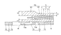
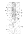
図1で示す燃料電池セルは、電解質膜1と、カソード側およびアノード側の触媒層2,2’と、から膜電極接合体3が形成され、これをカソード側およびアノード側のガス拡散層4,4’が挟持して電極体5が形成され、これをカソード側およびアノード側のガス流路層6A,6が挟持し、さらに、アノード側のガス流路層6に3層構造のセパレータ7が配されて構成される。
In the fuel cell shown in FIG. 1, a
なお、触媒層2,2’は電解質膜1に比してそれらの面積が狭小であり、したがって、電解質膜1の両側の触媒層2,2’の周縁には該触媒層2,2’が存在しない露出領域が形成され、この露出領域には、カソード側およびアノード側の不図示の保護フィルムが配されて、ガス拡散層4,4’から突出する毛羽が電解質膜1の露出領域に突き刺さるのを防護している構造であってもよい。
The catalyst layers 2, 2 ′ are narrower in area than the
ここで、膜電極接合体3を構成する電解質膜1は、たとえば、スルホン酸基やカルボニル基を持つフッ素系イオン交換膜、置換フェニレンオキサイドやスルホン化ポリアリールエーテルケトン、スルホン化ポリアリールエーテルスルホン、スルホン化フェニレンスルファイドなどの非フッ素系のポリマーなどから形成される。
Here, the
また、触媒層2,2’は、触媒が担持された導電性担体(粒子状のカーボン担体など)と、電解質と、分散溶媒(有機溶媒)と、を混合して触媒溶液(触媒インク)を生成し、これを電解質膜1やガス拡散層4,4’等の基材に塗工ブレードにて層状に引き伸ばして塗膜を形成し、温風乾燥炉等で乾燥することで触媒層が形成される。ここで、触媒溶液を形成する電解質は、プロトン伝導性ポリマーである、有機系の含フッ素高分子を骨格とするイオン交換樹脂、例えばパーフルオロカーボンスルフォン酸樹脂、スルホン化ポリエーテルケトン、スルホン化ポリエーテルスルホン、スルホン化ポリエーテルエーテルスルホン、スルホン化ポリスルホン、スルホン化ポリスルフィド、スルホン化ポリフェニレン等のスルホン化プラスチック系電解質、スルホアルキル化ポリエーテルエーテルケトン、スルホアルキル化ポリエーテルスルホン、スルホアルキル化ポリエーテルエーテルスルホン、スルホアルキル化ポリスルホン、スルホアルキル化ポリスルフィド、スルホアルキル化ポリフェニレンなどのスルホアルキル化プラスチック系電解質などを挙げることができる。なお、市販素材としては、ナフィオン(Nafion)(登録商標、デュポン社製)やフレミオン(Flemion)(登録商標、旭硝子株式会社製)などを挙げることができる。また、分散溶媒としては、メタノール、エタノール、1−プロパノール、2−プロパノール、エチレングリコール、ジエチレングリコール等のアルコール類、アセトン、メチルエチルケトン、ジメチルホルムアミド、ジメチルイミダゾリジノン、ジメチルスルホキシド、ジメチルアセトアミド、N−メチルピロリドン、プロピレンカーボネート、酢酸エチルや酢酸ブチルなどのエステル類、芳香族系あるいはハロゲン系の種々の溶媒を挙げることができ、さらには、これらを単独で、もしくは混合液として使用することができる。さらに、触媒が担持された導電性担体に関し、この導電性担体としては、カーボンブラック、カーボンナノチューブ、カーボンナノファイバーなどの炭素材料のほか、炭化ケイ素などに代表される炭素化合物などを挙げることができ、この触媒(金属触媒)としては、たとえば、白金や白金合金、パラジウム、ロジウム、金、銀、オスミウム、イリジウムなどのうちのいずれか一種を使用することができ、好ましくは白金または白金合金を使用するのがよい。さらに、この白金合金としては、たとえば、白金と、アルミニウム、クロム、マンガン、鉄、コバルト、ニッケル、ガリウム、ジルコニウム、モリブデン、ルテニウム、ロジウム、パラジウム、バナジウム、タングステン、レニウム、オスミウム、イリジウム、チタンおよび鉛のうちの少なくとも一種との合金を挙げることができる。
In addition, the catalyst layers 2 and 2 ′ are prepared by mixing a conductive carrier (particulate carbon carrier or the like) carrying a catalyst, an electrolyte, and a dispersion solvent (organic solvent) to form a catalyst solution (catalyst ink). The catalyst layer is formed by stretching it into a layer with a coating blade on the base material such as the
また、ガス拡散層4,4’は、拡散層基材と集電層(MPL)からなるものであり、拡散層基材としては、電気抵抗が低く、集電を行えるものであれば特に限定されるものではないが、たとえば、導電性無機物質を主とするものを挙げることができ、この導電性無機物質としては、ポリアクリロニトリルからの焼成体、ピッチからの焼成体、黒鉛及び膨張黒鉛等の炭素材やこれらのナノカーボン材料、ステンレススチール、モリブデン、チタン等を挙げることができる。また、拡散層基材の導電性無機物質の形態は特に限定されるものではなく、たとえば繊維状あるいは粒子状で用いられるが、ガス透過性の点から無機導電性繊維であって、特に炭素繊維が好ましい。無機導電性繊維を用いた拡散層基材としては、織布あるいは不織布いずれの構造のものも使用することができ、カーボンペーパーやカーボンクロスなどを挙げることができる。織布としては、平織、紋織、綴織など、特に限定されるものではなく、不織布としては、抄紙法、ウォータージェットパンチ法によるものなどが挙げられる。さらに、この炭素繊維としては、フェノール系炭素繊維、ピッチ系炭素繊維、ポリアクリロニトリル(PAN)系炭素繊維、レーヨン系炭素繊維などを挙げることができる。さらに、集電層はアノード側、カソード側の触媒層2,2’から電子を集める電極の役割を果たすものであり、導電性材料である、白金、パラジウム、ルテニウム、ロジウム、イリジウム、金、銀、銅及びこれらの化合物または合金、導電性炭素材料などから形成できる。
The
また、不図示の保護フィルムは、ポリテトラフルオロエチレン、PVDF(二フッ化ポリビニル)、ポリエチレン、ポリエチレンナフタレート(PEN)、ポリカーボネート、ポリフェニレンエーテル(PPE)、ポリプロピレン、ポリエステル、ポリアミド、コポリアミド、ポリアミドエラストマ、ポリイミド、ポリウレタン、ポリウレタンエラストマ、シリコーン、シリコンゴム、シリコンベースのエラストマなどから形成されるものである。
また、ガス流路層6A,6は、金属発泡焼結体もしくはエキスパンドメタルなどの金属多孔体から形成されている。
In addition, protective films not shown are polytetrafluoroethylene, PVDF (polyvinyl difluoride), polyethylene, polyethylene naphthalate (PEN), polycarbonate, polyphenylene ether (PPE), polypropylene, polyester, polyamide, copolyamide, polyamide elastomer. , Polyimide, polyurethane, polyurethane elastomer, silicone, silicon rubber, silicon-based elastomer and the like.
The gas flow path layers 6A and 6 are formed of a metal porous body such as a metal foam sintered body or an expanded metal.
さらに、3層構造のセパレータ7は、ステンレスやチタンからなる金属プレート71,72と、その間に、金属素材で冷却水流路やガス流路が形成された中間層73が介層されたものである。なお、樹脂素材の枠材を中間層とし、2枚の金属プレートの一方のプレートから多数のディンプル、もしくは流路画成用のリブが突出された形態であってもよい。なお、図示するセパレータ7では、自身が構成要素となる燃料電池セルのアノード側のガス流路層6に燃料ガスを供給するためのガス流路73aと、セルの積層姿勢において隣接するセルのカソード側のガス流路層6Aに酸化剤ガスを供給するためのガス流路73bが形成されており、さらには、不図示の冷却水流路が中間層73に形成されている。なお、セパレータ7には、不図示のガスケットのマニホールドに連通して、ガスや冷却水等が流通するマニホールドMが形成されている。
Further, the
図1に戻り、図示する燃料電池セルでは、電解質膜1はガス拡散層4,4’よりも側方に張り出しており、カソード側およびアノード側のガス流路層6A,6が電解質膜1よりも側方に張り出している。
Returning to FIG. 1, in the illustrated fuel cell, the
この構造により、たとえばガスケットを射出成形する際に電解質膜1が樹脂圧によって持ち上げられても、その端部はせいぜいガス流路層6Aの側面に到達するに過ぎず、電解質膜1の端部が外部に臨んでガスのクロスリーク路を形成することはない。
With this structure, for example, even when the
また、厚み:t1のアノード側のガス流路層6に対して、カソード側のガス流路層6Aは、その一般部61はアノード側のガス流路層6と同じ厚み:t1である一方で、その側方の張り出した箇所62の厚み:t2は、厚み:t1よりも厚く形成されている。より具体的には、ガス拡散層4と当接する領域まで厚み:t2を有しており、除々に厚みが減じられて厚み:t1に収斂しているものである。
Further, the
カソード側のガス流路層6Aの張り出した箇所62の厚みを相対的に厚くすることで、このガス流路層6Aに外力が作用しても、張り出した箇所62の高い曲げ剛性もしくはねじり剛性により、アノード側のガス流路層6側への曲がりや垂れが抑止され、双方の接触が防止される。なお、図示例以外にも、アノード側のガス流路層もカソード側と同様に、その張り出した箇所の厚みが厚く形成されていてもよい。
By relatively increasing the thickness of the protruding
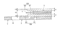
一方、図2で示す燃料電池セルでは、アノード側、カソード側双方のガス流路層6B,6Bの張り出した箇所63,63に関し、それぞれの対向面で凹部が形成されることで厚みが薄く形成され(一般部の厚み:t1に対して相対的に薄い厚み:t3)、双方の離間:t4が長くなっているものである。
On the other hand, in the fuel battery cell shown in FIG. 2, the protruding
この離間:t4により、仮にカソード側のガス流路層6Bが外力を受けて下方へ曲がった場合でも、その端部がアノード側のガス流路層6Bまで到達することがなく(そのように張り出した箇所63の長さが設計されている)、双方の接触が防止されている。
Even if the cathode-side gas
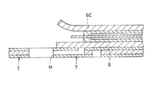
また、図3で示す燃料電池セルでは、カソード側のガス流路層6Cの張り出した箇所がアノード側のガス流路層6から離れるように予め折り曲げられており(図では上方に折り曲げられている)、この構成により、たとえばガスケットを射出成形した際に樹脂が側方から流れ込んできた場合でも、この樹脂圧によってカソード側のガス流路層6Cの張り出した箇所が下方へ曲げられることがなく、アノード側のガス流路層6と接触することが防止される。
Further, in the fuel cell shown in FIG. 3, the protruding portion of the cathode-side gas
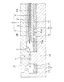
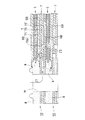
次に、図4〜6を参照して、燃料電池セルのガスケット成形〜燃料電池セルのスタッキングまでを概括する。なお、ここでは、図2で示す構造の燃料電池セルを取り上げる。 Next, referring to FIGS. 4 to 6, the process from the gasket molding of the fuel cell to the stacking of the fuel cell is outlined. Here, the fuel cell having the structure shown in FIG. 2 is taken up.
まず、電極体5と、アノード側およびカソード側の金属多孔体からなるガス流路層6B,6Bと、3層構造のセパレータ7を用意し、図4で示すように、固定型S1と可動型S2とからなる成形型のキャビティ内に下方から順に、セパレータ7、アノード側のガス流路層6B、電極体5、カソード側のガス流路層6Bを移載して型閉めする。
First, an
次いで、固定型S1に開設された注入孔Hを介して、樹脂をガスケット成形用キャビティC内に注入する(Y方向)。なお、図4の断面はガスケットにマニホールドが形成される箇所で切断した断面である。 Next, the resin is injected into the gasket forming cavity C through the injection hole H opened in the fixed mold S1 (Y direction). In addition, the cross section of FIG. 4 is a cross section cut | disconnected in the location where a manifold is formed in a gasket.
ここで、注入される樹脂としては、ブチル系ゴムやウレタン系ゴム、シリコーンRTVゴム、耐メタノール性を有するエポキシ系樹脂、エポキシ変性シリコーン樹脂、シリコーン樹脂、フッ素樹脂、炭化水素樹脂などを挙げることができる。 Here, examples of the resin to be injected include butyl rubber, urethane rubber, silicone RTV rubber, methanol-resistant epoxy resin, epoxy-modified silicone resin, silicone resin, fluorine resin, hydrocarbon resin, and the like. it can.
この射出成形により、セパレータ7の表面上にガスケットが直接成形されることから、セパレータとガスケットの密着領域は十分に接着され、したがって、これらの界面が外部に流体連通することはない。
Since the gasket is directly molded on the surface of the
図5は、図4の方法で製造された2つの燃料電池セル10,10を示しており、より具体的には、これらが積層される前の状態を示している。なお、たとえば300基の燃料電池セル10,…を積層して燃料電池スタックを形成する場合には、図4の方法でそれぞれの燃料電池セルを製造し、各燃料電池セル10のセパレータを具備しない側に積層姿勢で隣接する燃料電池セル10のセパレータ7を上載するようにして300基の燃料電池セル10,…を積層し、スタッキングが実行される。
FIG. 5 shows two
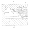
図6は、複数の燃料電池セル10,…が積層され、スタッキングされた後の2つの燃料電池セル10,10を取り出して図示したものである。なお、射出成形されてできたガスケット8にもマニホールドMが形成され、無端のシールリブ8aがマニホールドMを囲繞するようにガスケット8の上面(セパレータ7の存在しない面)に形成される。
FIG. 6 shows two
図6から明らかなように、積層姿勢の各燃料電池セル10,…がスタッキングされた際に、任意の燃料電池セル10は、自身の構成部材であるセパレータ7と隣接する燃料電池セル10のセパレータ7がその両側に配される構造となる。スタッキングされることによってマニホールドM周りのシールリブ8aが隣接する燃料電池セル10のセパレータ7にて潰され、シール構造が形成される。
As is clear from FIG. 6, when the
図示するマニホールドMは燃料ガスが流入するマニホールドであり、供給された燃料ガスは3層構造セパレータ7の中間層73からプレート71に亘って形成された供給ガス流路73aを介してアノード側のガス流路層6Bに供給される(Z1方向)。一方、ガスケット8の他の断面には酸化剤ガスが流入する別途のマニホールドが形成されており、この別途のマニホールドを介して酸化剤ガスが流入し、セパレータ7の中間層73からプレート72に亘って形成された供給ガス流路73bを介して隣接セルのカソード側の多孔体6Bに供給される(Z2方向)。
The illustrated manifold M is a manifold into which fuel gas flows, and the supplied fuel gas is gas on the anode side via a
上記する本発明の燃料電池の製造方法によれば、射出成形時の樹脂圧によって電解質膜の張り出し端部が持ち上げられ、該端部がセパレータと接着していない側のガスケットの端面に臨んで外部と流体連通し、ガスのクロスリーク路となることが効果的に抑止される。さらには、カソード側およびアノード側双方のガス流路層の張り出した箇所同士が接触することも防止されており、双方が接触して短絡するという問題も生じない。 According to the fuel cell manufacturing method of the present invention described above, the protruding end portion of the electrolyte membrane is lifted by the resin pressure at the time of injection molding, and the end portion faces the end face of the gasket on the side not bonded to the separator. This effectively suppresses the cross-leakage path of the gas. Further, the protruding portions of the gas flow path layers on both the cathode side and the anode side are also prevented from coming into contact with each other, and there is no problem of short-circuiting due to contact between both.
また、上記する燃料電池セルは、カソード側、アノード側のいずれか一方もしくは双方の側方の電極体よりも張り出した箇所の厚みを変化させただけの極めて簡易な構造変更によって、ガスのクロスリーク耐久の高い燃料電池となっていることから、その製造効率も高く、需要増に伴う燃料電池の大量生産に好適である。 In addition, the fuel cell described above has a gas cross-leakage by a very simple structural change by simply changing the thickness of the protruding part from the electrode body on either or both of the cathode side and the anode side. Since it is a highly durable fuel cell, its production efficiency is also high, and it is suitable for mass production of fuel cells as demand increases.
なお、実際に電気自動車等に車載される燃料電池システムは、燃料電池(燃料電池スタック)と、水素ガスや空気を収容する各種タンク、これらのガスを燃料電池に提供するためのブロア、燃料電池を冷却するためのラジエータ、燃料電池で生成された電力を蓄電するバッテリ、この電力で駆動する駆動モータ等から大略構成されるものである。 A fuel cell system that is actually mounted on an electric vehicle or the like includes a fuel cell (fuel cell stack), various tanks that store hydrogen gas and air, a blower for providing these gases to the fuel cell, and a fuel cell. It is mainly composed of a radiator for cooling the battery, a battery for storing electric power generated by the fuel cell, a drive motor driven by this electric power, and the like.
以上、本発明の実施の形態を図面を用いて詳述してきたが、具体的な構成はこの実施形態に限定されるものではなく、本発明の要旨を逸脱しない範囲における設計変更等があっても、それらは本発明に含まれるものである。 The embodiment of the present invention has been described in detail with reference to the drawings. However, the specific configuration is not limited to this embodiment, and there are design changes and the like without departing from the gist of the present invention. They are also included in the present invention.
1…電解質膜、2…カソード側の触媒層、2’…アノード側の触媒層、3…膜電極接合体、4…カソード側のガス拡散層(ガス透過層)、4’…アノード側のガス拡散層(ガス透過層)、5…電極体、6,6A,6B,6C…ガス流路層(ガス透過層)、61…一般部、62,63…張り出した箇所、71、72…プレート、73…中間層、8…ガスケット、10…燃料電池セル、M…マニホールド、S1…固定型、S2…可動型、H…注入孔、C…キャビティ
DESCRIPTION OF
Claims (8)
2つの前記ガス透過層はいずれも電解質膜よりも側方に張り出しており、
2つの前記ガス透過層の側方に張り出した箇所のいずれか一方、もしくは双方の厚みは、ガス透過層の他の箇所の厚みに対して変化しており、これが、2つのガス透過層の側方に張り出した箇所同士の接触防止手段となっている、燃料電池セルの構成部材ユニット。 A fuel cell comprising: a membrane electrode assembly comprising an electrolyte membrane and catalyst layers on both sides thereof; a gas permeable layer disposed on both sides of the membrane electrode assembly; and a gasket formed on the periphery thereof. In the component member unit,
Each of the two gas permeable layers protrudes laterally from the electrolyte membrane,
The thickness of one or both of the portions projecting to the side of the two gas permeable layers changes with respect to the thickness of the other portions of the gas permeable layer, and this is the side of the two gas permeable layers. A component unit of a fuel cell, which serves as a means for preventing contact between the protruding portions.
Priority Applications (1)
| Application Number | Priority Date | Filing Date | Title |
|---|---|---|---|
| JP2008326012A JP2010146977A (en) | 2008-12-22 | 2008-12-22 | Fuel battery, fuel battery cell, and constituting member unit of the same |
Applications Claiming Priority (1)
| Application Number | Priority Date | Filing Date | Title |
|---|---|---|---|
| JP2008326012A JP2010146977A (en) | 2008-12-22 | 2008-12-22 | Fuel battery, fuel battery cell, and constituting member unit of the same |
Publications (1)
| Publication Number | Publication Date |
|---|---|
| JP2010146977A true JP2010146977A (en) | 2010-07-01 |
Family
ID=42567147
Family Applications (1)
| Application Number | Title | Priority Date | Filing Date |
|---|---|---|---|
| JP2008326012A Withdrawn JP2010146977A (en) | 2008-12-22 | 2008-12-22 | Fuel battery, fuel battery cell, and constituting member unit of the same |
Country Status (1)
| Country | Link |
|---|---|
| JP (1) | JP2010146977A (en) |
-
2008
- 2008-12-22 JP JP2008326012A patent/JP2010146977A/en not_active Withdrawn
Similar Documents
| Publication | Publication Date | Title |
|---|---|---|
| US9385387B2 (en) | Method for manufacturing reinforced membrane electrode assembly and reinforced membrane electrode assembly | |
| US20140045101A1 (en) | Fuel cell module and fuel cell stack | |
| JP5181969B2 (en) | Fuel cell | |
| JP2010282940A (en) | Fuel cell | |
| JP5181950B2 (en) | Fuel cell | |
| JP6212925B2 (en) | Assembly assembly | |
| JP2010182483A (en) | Fuel battery cell and fuel battery | |
| JP2010244871A (en) | Fuel cell | |
| JP2010003470A (en) | Fuel cell | |
| JP2010211964A (en) | Method of manufacturing fuel battery | |
| JP2011129367A (en) | Fuel cell | |
| JP2010123343A (en) | Fuel cell, and method of manufacturing cell of fuel cell | |
| JP2011129265A (en) | Fuel cell | |
| JP2010182636A (en) | Method of manufacturing fuel cell | |
| JP2010146977A (en) | Fuel battery, fuel battery cell, and constituting member unit of the same | |
| JP2010218717A (en) | Fuel cell | |
| JP2010186627A (en) | Fuel battery | |
| JP2010097895A (en) | Fuel cell | |
| JP2010140716A (en) | Fuel cell | |
| JP2010186717A (en) | Method of manufacturing fuel battery cell | |
| JP2010165558A (en) | Fuel battery, fuel battery cell, and composition member unit thereof | |
| JP2010140682A (en) | Fuel battery, fuel battery cell, and component unit thereof | |
| JP2010198763A (en) | Fuel cell | |
| JP2010186711A (en) | Fuel cell | |
| JP5316244B2 (en) | Fuel cell |
Legal Events
| Date | Code | Title | Description |
|---|---|---|---|
| A300 | Withdrawal of application because of no request for examination |
Free format text: JAPANESE INTERMEDIATE CODE: A300 Effective date: 20120306 |