JP2010146902A - Lighting system - Google Patents
Lighting system Download PDFInfo
- Publication number
- JP2010146902A JP2010146902A JP2008324147A JP2008324147A JP2010146902A JP 2010146902 A JP2010146902 A JP 2010146902A JP 2008324147 A JP2008324147 A JP 2008324147A JP 2008324147 A JP2008324147 A JP 2008324147A JP 2010146902 A JP2010146902 A JP 2010146902A
- Authority
- JP
- Japan
- Prior art keywords
- light emitting
- emitting diode
- light
- lighting circuit
- pair
- Prior art date
- Legal status (The legal status is an assumption and is not a legal conclusion. Google has not performed a legal analysis and makes no representation as to the accuracy of the status listed.)
- Pending
Links
Images
Landscapes
- Arrangement Of Elements, Cooling, Sealing, Or The Like Of Lighting Devices (AREA)
- Non-Portable Lighting Devices Or Systems Thereof (AREA)
- Led Device Packages (AREA)
Abstract
【課題】発光ダイオードの高温化を防止または抑制することができる照明装置を提供する。
【解決手段】発光ダイオード16eの背面側にヒートシンク16a,16bを配設した一対の発光ユニット15a,15bと;発光ダイオード16eの点灯回路基板18cを収容ボックス18a内に収容した点灯回路ユニット18と;所定の間隔を置いて複数の投光開口部が設けられており、この複数の投光開口部に発光ユニットがそれぞれ配設されると共に、これら発光ユニット15a,15bの間に点灯回路ユニット18を配設した本体8を有する灯体2と;を具備している。
【選択図】 図1Provided is a lighting device capable of preventing or suppressing a high temperature of a light emitting diode.
A pair of light emitting units (15a, 15b) in which heat sinks (16a, 16b) are disposed on the back side of the light emitting diode (16e); a lighting circuit unit (18) in which a lighting circuit board (18c) of the light emitting diode (16e) is housed in a housing box (18a); A plurality of light projecting openings are provided at predetermined intervals. Light emitting units are respectively disposed in the light projecting openings, and a lighting circuit unit 18 is provided between the light emitting units 15a and 15b. A lamp body 2 having a main body 8 disposed therein.
[Selection] Figure 1
Description
光源としてLED(発光ダイオード)を用いた照明装置に関する。 The present invention relates to a lighting device using an LED (light emitting diode) as a light source.
従来、この種の照明装置の一例としては、空港の滑走路やその誘導路の出入口に設置される滑走路警戒灯等の航空標識灯がある。 Conventionally, as an example of this type of lighting device, there is an air traffic light such as a runway warning light installed at an airport runway or an entrance / exit of the taxiway.
このような従来のLED滑走路警戒灯では、一つの密閉空間に形成された灯体内に、発光ダイオードを具備した発光ユニットと、発光ダイオードの点灯回路とを、遮熱せずに単に、収容したものが知られている(例えば特許文献1,2参照)。
しかしながら、このような従来の滑走路警戒灯では、一つの密閉空間を形成する灯体内に、発光ダイオードとその点灯回路とを共に遮熱せずに単に収容するので、発光ダイオードが点灯回路の発熱からの熱的影響を受け易くなり、発光ダイオードが高温化して劣化し易くなる上に、発光効率が低下し易い。このために、点灯後の温度ドリフトによる光度低下が大きな課題となっている。 However, in such a conventional runway warning light, since the light emitting diode and its lighting circuit are simply housed in the lamp body forming one sealed space without being shielded from heat, the light emitting diode is protected from the heat generated by the lighting circuit. The light emitting diode is likely to be deteriorated due to high temperature, and the light emission efficiency is likely to be lowered. For this reason, the luminous intensity fall by the temperature drift after lighting is a big subject.
また、特許文献1記載の滑走路警戒灯では、密閉空間を形成する灯体内の空気をファンにより単に撹拌して、本体内の発光ダイオードや点灯回路等を冷却を図っているのに過ぎないので、その冷却効果を向上させるためには灯体内の空間を増大させる必要がある。このために、本体の大形化を招くという課題がある。 In the runway warning light described in Patent Document 1, the air in the lamp body forming the sealed space is simply stirred by a fan to cool the light emitting diodes and lighting circuits in the main body. In order to improve the cooling effect, it is necessary to increase the space in the lamp body. For this reason, there is a problem that the main body is increased in size.
また、灯体が大形化すると、外気温度が低下したときに、結露が発生し易くなり、光源の前方で結露が発生したときに、光度が低下するという課題も発生する。 Further, when the lamp body is increased in size, dew condensation is likely to occur when the outside air temperature is lowered, and when the dew condensation occurs in front of the light source, there is a problem that the luminous intensity is decreased.
本発明は、発光ダイオードの高温化を防止または抑制することができる照明装置を提供することを目的とする。 An object of this invention is to provide the illuminating device which can prevent or suppress the high temperature of a light emitting diode.
請求項1に係る照明装置は、発光ダイオードの背面側にヒートシンクを配設した複数の発光ユニットと;発光ダイオードの点灯回路を容器内に収容した点灯回路ユニットと;所定の間隔を置いて複数の投光開口部が設けられており、この複数の投光開口部に発光ユニットがそれぞれ配設されると共に、これら発光ユニットの間に点灯回路ユニットを配設した本体を有する灯体と;を具備していることを特徴とする。 The lighting device according to claim 1 includes a plurality of light emitting units provided with a heat sink on the back side of the light emitting diode; a lighting circuit unit in which a lighting circuit of the light emitting diode is housed in a container; and a plurality of light emitting units at a predetermined interval. And a lamp body having a main body in which a light emitting unit is disposed in each of the plurality of light projecting openings and a lighting circuit unit is disposed between the light emitting units. It is characterized by that.
この発明において、各発光ユニットの発光ダイオードは単数でも複数でもよく、その発光色はいずれでもよい。また、「発光ダイオードの背面にヒートシンクを配設する」とは、例えば放熱フィンを具備したヒートシンクのベースに、発光ダイオードの背面を直接または間接に取り付ける場合をいう。発光ダイオードの背面にヒートシンクを配設しているので、この発光ダイオードの発熱をヒートシンクにより放熱し、冷却することができる。 In the present invention, the light emitting diode of each light emitting unit may be singular or plural, and the color of the emitted light may be any. Further, “disposing the heat sink on the back surface of the light emitting diode” means, for example, a case where the back surface of the light emitting diode is directly or indirectly attached to the base of the heat sink having the heat radiating fins. Since the heat sink is disposed on the back surface of the light emitting diode, the heat generated by the light emitting diode can be dissipated by the heat sink and cooled.
さらに、点灯回路ユニットは、例えば一端が開口した有底筒状の容器の当該底部内面に、点灯回路基板を取り付け、この容器の開口端を灯体の本体に取り付けることが好ましい。点灯回路基板を容器内に収容しているので、この容器により点灯回路の発熱を遮熱することができる。このために、発光ユニットの発光ダイオードに与える熱的影響を低減できる。 Further, it is preferable that the lighting circuit unit is attached to the inner surface of the bottom of the bottomed cylindrical container having one end opened, for example, and the opening end of the container is attached to the main body of the lamp body. Since the lighting circuit board is accommodated in the container, the heat generation of the lighting circuit can be shielded by the container. For this reason, the thermal influence given to the light emitting diode of the light emitting unit can be reduced.
請求項2に係る照明装置は、灯体には、投光開口部を覆うように取り付ける透光性部材と、発光ユニットおよび点灯回路ユニットとが防水手段を介してそれぞれ取り付けられていることを特徴とする。
The lighting device according to
この発明において、「防水手段」とは、例えば弾性体からなるパッキンやシリコーン樹脂等の硬化性充填材料である。 In the present invention, the “waterproofing means” is a curable filling material such as packing made of an elastic material or silicone resin.
請求項3に係る照明装置は、ヒートシンクの背面側に所定の間隙を置いて保護カバーが配設されていることを特徴とする。
The illumination device according to
この発明において、ヒートシンクの背面側と保護カバーとの間に間隙があるので、この間隙の通風によるヒートシンクの放熱性能の向上を図ることができる。 In the present invention, since there is a gap between the back surface side of the heat sink and the protective cover, the heat dissipation performance of the heat sink can be improved by ventilation of the gap.
保護カバーは、外部からヒートシンクを保護するためのものである。また、太陽熱等外部からの熱がヒートシンクに直接放射され、熱伝達されることを防止または抑制しヒートシンクに日影を形成し得る部材であってもよい。その保護目的に応じた材質および形状を有していればよい。 The protective cover is for protecting the heat sink from the outside. Moreover, the member which can prevent or suppress that the heat from the outside, such as solar heat, is directly radiated and transferred to the heat sink to form a shade on the heat sink. What is necessary is just to have the material and shape according to the protection objective.
請求項1記載の照明装置によれば、発光ダイオードの発熱をヒートシンクにより放熱するので、その放熱効果の向上を図ることができる。また、点灯回路の発熱を、その容器により遮熱することができる。このために、点灯回路の発熱が発光ダイオードに与える熱的影響を低減できるので、発光ダイオードの高温化を防止または抑制することができる。その結果、灯体の大形化と、その大形化に伴う結露の発生を防止または抑制することができる。 According to the illumination device of the first aspect, since the heat generated by the light emitting diode is radiated by the heat sink, the heat radiation effect can be improved. Further, the heat generated in the lighting circuit can be shielded by the container. For this reason, since the thermal influence which the heat_generation | fever of a lighting circuit has on a light emitting diode can be reduced, the high temperature of a light emitting diode can be prevented or suppressed. As a result, it is possible to prevent or suppress the increase in size of the lamp body and the occurrence of condensation due to the increase in size.
請求項2記載の照明装置によれば、灯体の本体には、投光開口部を覆う透光性部材と、発光ユニットおよび点灯回路ユニットとが防水手段をそれぞれ介して取り付けられているので、灯体の防水性を向上させることができる。このために、照明装置を屋外に設置することができる。
According to the illuminating device of
請求項3記載の照明装置によれば、ヒートシンクを外部から保護するので、その放熱効果を維持することができる。 According to the illumination device of the third aspect, since the heat sink is protected from the outside, the heat dissipation effect can be maintained.
以下、本発明の実施形態を添付図面に基づいて説明する。なお、これら複数の添付図面中、同一または相当部分には同一符号を付している。 Hereinafter, embodiments of the present invention will be described with reference to the accompanying drawings. In addition, the same code | symbol is attached | subjected to the same or an equivalent part in these several accompanying drawings.
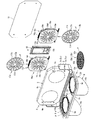
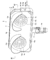
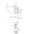
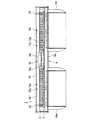
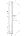
図1は本発明の一実施形態に係る発光ダイオード信号灯の分解斜視図、図2は図1で示す発光ダイオード信号灯の斜視図、図3は図2の側面図、図4は図2のIV−IV線断面図、図5は図2の平面図である。 1 is an exploded perspective view of a light emitting diode signal lamp according to an embodiment of the present invention, FIG. 2 is a perspective view of the light emitting diode signal lamp shown in FIG. 1, FIG. 3 is a side view of FIG. 2, and FIG. FIG. 5 is a plan view of FIG. 2.
これら図2、図3に示すように発光ダイオード信号灯1は、例えば光度3000CD型に構成されており、アルミニウム製等の横長角筒状の灯体2の左右両側面を、コ字状帯板状の支持枠3により揺動可能に支持し、この支持枠3の底部中央部にポール4の図中上端を固定している。
As shown in FIGS. 2 and 3, the light-emitting diode signal lamp 1 is configured, for example, in a luminous intensity 3000 CD type, and left and right side surfaces of a horizontally long rectangular
ポール4は、その全体が例えばアルミニウム製の略円筒により形成され、可折接手4aを設けている。可折接手4aは、その図中上端部に設けた取付金具(図示省略)により支持枠3の底部中央に取り付けられている。可折接手4aの内部には、外部から図示しない電源コードが導入され、この電源コードは、後述する発光ダイオードに電気的に接続されている。可折接手4aは、空港の滑走路と誘導路との交差点近傍等所定位置に設置されている支持部材(図示省略)に取り付けられ、支持部材において重力の作用方向に対して鉛直方向および水平方向に回動することができる。これにより、灯体2は、重力の作用方向に対して鉛直方向および水平方向に回動される。
The entire pole 4 is formed of, for example, a substantially cylindrical cylinder made of aluminum, and is provided with a
支持枠3は、そのコ字状開口内に、角筒状の灯体2の図中ほぼ下半部を収容した状態で、この灯体2の左右両側面に、左右一対のコ字状開口端部に設けた一対のヒンジピン5a,5bを取付け、灯体2を図1中前後方向に揺動可能に支持している。また、支持枠3はその左右一対の側板部に、一対のヒンジピン5a,5bよりも図2中、若干下方において、その揺動角を保持するための左右一対の締付けボルト6a,6bを設けている。これら締付けボルト6a,6bは灯体2の左右両側面にねじ込み可能に配設されて、支持枠2の一対の円弧状スリット7a,7bを垂直方向外方へ挿通して外部に突出し、この突出外端部に、スリット7a,7bの図2中、上下方向の開口幅よりも大径のつまみ7a1,7b1を設け、これらつまみ7a1,7b1を手で所要方向に回動させて締め付けることにより、灯体2の揺動角を保持するようになっている。
The
図1に示すように灯体2は、偏平有底角筒状の本体8と、この本体8の底部に相当する前面板8aのほぼ全面を覆う偏平有底角筒状のカバー9とを具備している。図2に示すようにカバー9は、その図中下端部に設けた左右一対のヒンジ10a,10bにより本体8に揺動可能に連結され、カバー9が図中上方で開閉可能に取り付けられている。また、これら本体8とカバー9の図1,図2中、上端部には、カバー9が本体前面板8aを覆う閉状態を保持するラチェット機構(図示省略)が配設されている。このラチェット機構は、そのラチェット状態を解除する解除ボタン(図示省略)があり、この解除ボタンの押圧等の操作により、そのラチェット状態を解除することにより、カバー9を適宜開閉できる。
As shown in FIG. 1, the
カバー9は、その偏平有底角筒の底部に相当する前面板9aに、左右一対の円形等の投光開口9b,9cをそれぞれ形成している。図1に示すように、これら一対の投光開口9b,9cの外面側には、その開口周縁部に円形のスポンジ製やゴム製のパッキンP,Pをそれぞれ貼着している。そして、これら外側の左右一対のパッキンP,P上には、透光性部材の一例である例えばアクリル等の樹脂や強化ガラス製等で円形平板状のレンズ11a,11bを固着して照射窓12a,12bに構成している。
The
一方、一対の投光開口9b,9cの内面側には、これら投光開口9b,9cよりも若干大径の円板状のコントラスト板13a,13bがそれぞれ固着されている。これらコントラスト板13a,13bは、後述する複数の発光ダイオードの発光部に対応する部分を透光部13cにそれぞれ形成し、これら透光部13c以外の部分13dを、その透光部13cを透過する光の光色とコントラストを強調し得る黒色等所要色に着色している。これらコントラスト板13a,13bの外周縁部には円環状のパッキンPをそれぞれ取り付けている。一方、図2にも示すようにカバー9の前面板9aの外面(前面)には、左右一対の照射窓12a,12bの図中上部に円弧つば状のフード14a,14bをそれぞれ突設している。これらフード14a,14bにより、左右の照射窓12a,12bに直射日光が当ってコントラストが低下することを防止すると共に、雨水が直接照射窓12a,12bに当ることの防止を図っている。
On the other hand, disc-
そして、偏平有底角筒状の本体8は、その底部に相当する前面板8aに、照射窓12a,12bに対応してほぼ同形同大の透孔8b,8cを投光開口として同心状に形成している。これら一対の透孔8b,8cの内面側には、左右一対の発光ユニット15a,15bの前面を同心状に当接させて本体に固着している。これら発光ユニット15a,15bはヒートシンク16a,16bのベース16c,16dの前面に、複数のLED(発光ダイオード)16e,16e,…を、円形や楕円等の所要の配光パターンで光を放射するように所要の配列で配列し、その背面をそれぞれ固着している。各LED16eは、例えば小形矩形の基板上に黄色発光のLED本体を配設し、このLED本体上に、レンズを一体的に形成してなるレンズホルダを同心状に配設して構成されている。これらLED基板の背面はヒートシンク16a,16bの平板状のベース16c,16dの前面に直接固着されている。これらベース16c,16dの背面には複数の放熱フィン16f,16gをそれぞれ配設している。
The flat bottomed rectangular tube-shaped
そして、これらヒートシンク16a,16bのベース16c,16dの前面上には、円板状の整列板17a,17bを同心状に固着している。これら整列板17a,17bは、透明円板よりなる基板17c,17dに、上記LED16eの平面形状とその配列にそれぞれ適合した、例えば複数の矩形の透孔17e,17e,17e,…をそれぞれ形成し、透明基板17c,17dの外周縁部には、パッキンP,Pをそれぞれ嵌合し固定している。そして、整列板17a,17bは、その透孔17e,17e,17e,…内に各LED16eのレンズ等の前面発光部を挿通し、若干突出させた状態でパッキンPがそれぞれ密着するようにヒートシンク16a,16bのベース16c,16dに固着している。
Disc-shaped
図1,図4に示すように、本体8は、その前面板8aの内面に、左右一対の発光ユニット16a,16bの間において、点灯回路ユニット18を固定している。点灯回路ユニット18は、容器の一例である偏平有底角筒状の収容ボックス18a内に、点灯回路基板18cを配設している。
As shown in FIGS. 1 and 4, the
すなわち、収容ボックス18aは、その開口端に矩形枠状の外向フランジ18bを一体に突設し、この開口端の外周縁部上に矩形枠状のパッキンPを同心状に固着している。また、収容ボックス18aは、その底部内面に点灯回路基板18cを固着している。点灯回路基板18cは、左右一対の発光ユニット15a,15bの各LED16eをほぼ同等の明るさで、点灯させる調光可能の点灯回路を基板に形成している。この点灯回路基板18cはその出力側を、図示省略のリード線またはハーネスを介して各LED16eに電気的に接続する一方、その入力側を図示しない電源線に接続している。また、この収容ボックス18aは、その開口端側を、そのパッキンPを本体前面板8aの内面に密着させた状態で固着している。
That is, the
そして、図3〜図5に示すように、左右一対のヒートシンク16a,16bの背面側に、この背面を所要の間隙を置いて覆うように、保護カバーの一例であるほぼ矩形平板状の遮熱板19を本体前面板8aに、軸の長い複数の長軸ボルト20,20,…により固定している。
As shown in FIGS. 3 to 5, a substantially rectangular flat plate-like heat shield as an example of a protective cover is provided on the back side of the pair of left and right heat sinks 16 a and 16 b so as to cover the back side with a necessary gap. The
発光ダイオード信号灯1は、以上のように構成されているので、点灯回路ユニット18から左右一対の発光ユニット15a,15bの各LED16eに所要の電力が給電されると、これらLED16eが点灯し、左右一対の発光ユニット15a,15bから、例えば黄色光等の可視光が放射される。この放射光は、さらに左右一対のコントラスト板13a,13b、レンズ11a,11bをそれぞれ通過して外部に放射される。この放射光は点灯回路ユニット18により調光される。
Since the light-emitting diode signal lamp 1 is configured as described above, when necessary power is supplied from the
そして、発光ダイオード16eの背面にヒートシンク16a,16bを配設しているので、この発光ダイオード16eの発熱をヒートシンク16a,16bによりそれぞれ放熱し、冷却することができる。
Since the
さらに、点灯回路ユニット18は、例えば一端が開口した有底筒状の収容ボックス18a内に収容しているので、この収容ボックス18aにより点灯回路基板18cの発熱を遮熱することができる。このために、発光ユニット15a,15bの発光ダイオード16eに与える熱的影響を低減できるので、発光ダイオード16eの高温化を防止または抑制できる。
Furthermore, since the
また、遮熱板19は、外部から異物がぶつかってヒートシンクが破損したり、汚れたりすることが防止できる。また、遮熱板19は、ヒートシンク16a,16bの背面を、所要の間隙を置いて覆うので、ヒートシンク16a,16bに日光が直射することを防止または抑制することができる。さらに、ヒートシンク16a,16bの背面側と遮熱板18との間に間隙があるので、この間隙の通風によりヒートシンク16a,16bの放熱性能の向上を図ることができる。このために、発光ダイオード16eの高温化をさらに防止または抑制することができる。その結果、灯体2の大形化と、その大形化に伴う結露の発生を防止または抑制することができる。
Moreover, the
1…照明装置、2…灯体、3…支持枠、4…ポール、4a…可折継手、5a,5b…一対のヒンジピン、6a,6b…一対の締付ボルト、8…本体、8a…本体の前面板、8b,8c…投光開口、9…カバー、11a,11b…左右一対のレンズ(透光性部材)、13a,13b…一対のコントラスト板、14a,14b…一対のフード、15a,15b…一対の発光ユニット、16a,16b…一対のヒートシンク、16c,16d…一対のベース、16e…発光ダイオード(LED)、17a,17b…一対の整列板、18…点灯回路ユニット、18a…収容ボックス(容器)、19…遮熱板。 DESCRIPTION OF SYMBOLS 1 ... Illuminating device, 2 ... Lamp body, 3 ... Support frame, 4 ... Pole, 4a ... Foldable joint, 5a, 5b ... A pair of hinge pins, 6a, 6b ... A pair of clamping bolt, 8 ... Main body, 8a ... Main body Front plate, 8b, 8c ... Projection opening, 9 ... Cover, 11a, 11b ... A pair of left and right lenses (translucent member), 13a, 13b ... A pair of contrast plates, 14a, 14b ... A pair of hoods, 15a, 15b: a pair of light emitting units, 16a, 16b ... a pair of heat sinks, 16c, 16d ... a pair of bases, 16e ... a light emitting diode (LED), 17a, 17b ... a pair of alignment plates, 18 ... a lighting circuit unit, 18a ... a storage box (Container), 19 ... heat shield.
Claims (3)
発光ダイオードの点灯回路を容器内に収容した点灯回路ユニットと;
所定の間隔を置いて複数の投光開口部が設けられており、この複数の投光開口部に発光ユニットがそれぞれ配設されると共に、これら発光ユニットの間に点灯回路ユニットを配設した本体を有する灯体と;
を具備していることを特徴とする照明装置。 A plurality of light emitting units having a heat sink disposed on the back side of the light emitting diode;
A lighting circuit unit that houses a lighting circuit of a light emitting diode in a container;
A plurality of light projecting openings are provided at predetermined intervals, a light emitting unit is disposed in each of the light projecting openings, and a lighting circuit unit is disposed between the light emitting units. A lamp body having;
An illumination device comprising:
Priority Applications (2)
| Application Number | Priority Date | Filing Date | Title |
|---|---|---|---|
| JP2008324147A JP2010146902A (en) | 2008-12-19 | 2008-12-19 | Lighting system |
| CN2009202926199U CN201593726U (en) | 2008-12-19 | 2009-12-17 | lighting device |
Applications Claiming Priority (1)
| Application Number | Priority Date | Filing Date | Title |
|---|---|---|---|
| JP2008324147A JP2010146902A (en) | 2008-12-19 | 2008-12-19 | Lighting system |
Publications (1)
| Publication Number | Publication Date |
|---|---|
| JP2010146902A true JP2010146902A (en) | 2010-07-01 |
Family
ID=42567085
Family Applications (1)
| Application Number | Title | Priority Date | Filing Date |
|---|---|---|---|
| JP2008324147A Pending JP2010146902A (en) | 2008-12-19 | 2008-12-19 | Lighting system |
Country Status (2)
| Country | Link |
|---|---|
| JP (1) | JP2010146902A (en) |
| CN (1) | CN201593726U (en) |
Cited By (3)
| Publication number | Priority date | Publication date | Assignee | Title |
|---|---|---|---|---|
| JP2014154434A (en) * | 2013-02-12 | 2014-08-25 | Dream:Kk | Led projector |
| JP2021529425A (en) * | 2018-06-29 | 2021-10-28 | 北京納米維景科技有限公司Nanovision Technology (Beijing) Co., Ltd. | Scanning X-ray source and its image formation system |
| JP2024097051A (en) * | 2017-01-13 | 2024-07-17 | 株式会社ホタルクス | lamp |
Families Citing this family (1)
| Publication number | Priority date | Publication date | Assignee | Title |
|---|---|---|---|---|
| CN102734775A (en) * | 2012-06-19 | 2012-10-17 | 江苏爱科新能源科技有限公司 | Heat insulation device for light emitting diode (LED) |
-
2008
- 2008-12-19 JP JP2008324147A patent/JP2010146902A/en active Pending
-
2009
- 2009-12-17 CN CN2009202926199U patent/CN201593726U/en not_active Expired - Fee Related
Cited By (4)
| Publication number | Priority date | Publication date | Assignee | Title |
|---|---|---|---|---|
| JP2014154434A (en) * | 2013-02-12 | 2014-08-25 | Dream:Kk | Led projector |
| JP2024097051A (en) * | 2017-01-13 | 2024-07-17 | 株式会社ホタルクス | lamp |
| JP2021529425A (en) * | 2018-06-29 | 2021-10-28 | 北京納米維景科技有限公司Nanovision Technology (Beijing) Co., Ltd. | Scanning X-ray source and its image formation system |
| JP7300745B2 (en) | 2018-06-29 | 2023-06-30 | 北京納米維景科技有限公司 | Scanning X-ray source and its imaging system |
Also Published As
| Publication number | Publication date |
|---|---|
| CN201593726U (en) | 2010-09-29 |
Similar Documents
| Publication | Publication Date | Title |
|---|---|---|
| CN101592326B (en) | Light emitting diode (LED) lamp | |
| US9651238B2 (en) | Thermally dissipated lighting system | |
| RU2010130662A (en) | LED LUMINAIRES FOR WIDE-SCALE ARCHITECTURAL LIGHTING | |
| JP3196336U (en) | Car lighting equipment | |
| JP2010146902A (en) | Lighting system | |
| KR101393509B1 (en) | Led lamp for tunnel | |
| JP6586306B2 (en) | LED lighting fixtures | |
| KR101086893B1 (en) | LED Street Light | |
| JP2015167089A (en) | Lighting device | |
| KR101020623B1 (en) | LED luminaires | |
| KR101400376B1 (en) | Led electric light module with waterproofing and heat dissipation | |
| KR200456082Y1 (en) | LED lamp apparatus | |
| KR102416269B1 (en) | LED Lighting Module Containing Phase Change Material | |
| KR101050086B1 (en) | LED lighting fixtures to prevent the ingress of moisture, bugs and dust | |
| KR100581392B1 (en) | Medium Light Aviation Obstruction Light | |
| JP6849943B2 (en) | Lighting device | |
| KR101075246B1 (en) | A led street lamp | |
| WO2015133196A1 (en) | Lighting device and led light source unit | |
| JP5842092B2 (en) | Outdoor lighting fixtures | |
| CN207621939U (en) | A kind of warning lamp | |
| TWI396808B (en) | Led lamp | |
| JP6604860B2 (en) | LED lighting equipment | |
| CN215446139U (en) | LED windowsill lamp with good heat dissipation performance | |
| TWM453083U (en) | Lamp | |
| TWM428303U (en) | Modualized light emitting diode lamp |