JP2010146836A - Cable mounting method - Google Patents
Cable mounting method Download PDFInfo
- Publication number
- JP2010146836A JP2010146836A JP2008322034A JP2008322034A JP2010146836A JP 2010146836 A JP2010146836 A JP 2010146836A JP 2008322034 A JP2008322034 A JP 2008322034A JP 2008322034 A JP2008322034 A JP 2008322034A JP 2010146836 A JP2010146836 A JP 2010146836A
- Authority
- JP
- Japan
- Prior art keywords
- coaxial cable
- end portion
- hole
- connector cover
- base end
- Prior art date
- Legal status (The legal status is an assumption and is not a legal conclusion. Google has not performed a legal analysis and makes no representation as to the accuracy of the status listed.)
- Granted
Links
Images


Classifications
-
- H—ELECTRICITY
- H01—ELECTRIC ELEMENTS
- H01R—ELECTRICALLY-CONDUCTIVE CONNECTIONS; STRUCTURAL ASSOCIATIONS OF A PLURALITY OF MUTUALLY-INSULATED ELECTRICAL CONNECTING ELEMENTS; COUPLING DEVICES; CURRENT COLLECTORS
- H01R43/00—Apparatus or processes specially adapted for manufacturing, assembling, maintaining, or repairing of line connectors or current collectors or for joining electric conductors
- H01R43/20—Apparatus or processes specially adapted for manufacturing, assembling, maintaining, or repairing of line connectors or current collectors or for joining electric conductors for assembling or disassembling contact members with insulating base, case or sleeve
-
- H—ELECTRICITY
- H01—ELECTRIC ELEMENTS
- H01R—ELECTRICALLY-CONDUCTIVE CONNECTIONS; STRUCTURAL ASSOCIATIONS OF A PLURALITY OF MUTUALLY-INSULATED ELECTRICAL CONNECTING ELEMENTS; COUPLING DEVICES; CURRENT COLLECTORS
- H01R9/00—Structural associations of a plurality of mutually-insulated electrical connecting elements, e.g. terminal strips or terminal blocks; Terminals or binding posts mounted upon a base or in a case; Bases therefor
- H01R9/03—Connectors arranged to contact a plurality of the conductors of a multiconductor cable, e.g. tapping connections
- H01R9/05—Connectors arranged to contact a plurality of the conductors of a multiconductor cable, e.g. tapping connections for coaxial cables
- H01R9/0518—Connection to outer conductor by crimping or by crimping ferrule
Abstract
Description
本発明は、ケーブル取付方法に関する。 The present invention relates to a cable mounting method.
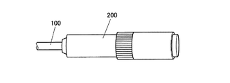
従来、電子機器との接続を容易にすべく、図9に示すように、同軸ケーブル100の先端部には、導電性のコネクタカバー200が接続されている。同軸ケーブル100とコネクタカバー200との接続部分について詳細に説明する。図10は、同軸ケーブル100及びコネクタカバー200の取付構造を示す斜視図である。図10に示すように同軸ケーブル100の内部導体101に対しては中心ピン102が取り付けられている。また、同軸ケーブル100の先端部には、内部導体101及び中心ピン102を保持する保持部材103が取り付けられている。保持部材103の基端側には、同軸ケーブル100とコネクタカバー200との隙間を埋めるスペーサー104が設けられている。スペーサー104は、同軸ケーブル100に取り付けられていて、その先端部は同軸ケーブル100の外部導体105が折り返されて被覆されている。これにより、外部導体105とコネクタカバー200とが電気的に接続され、外部導体105がコネクタカバー200を介して接地されることになる。
一方、コネクタカバー200の内部には、保持部材103と係合し中心ピン102の位置決めを行う突部201が内側に向けて突出している。このため、コネクタカバー200に対して同軸ケーブル100を取り付ける際には、電子機器と接続される端子部側の先端部202からではなく、基端部203から挿入されることになる(矢印Y1)。そして、挿入後においては、基端部203をかしめることで同軸ケーブル100とコネクタカバー200とが固定される。
Conventionally, a
On the other hand, a
また、コネクタカバー200と外部導体105とを接触させる接地法以外にも、例えば特許文献1に示すように、コネクタカバーとは別体のアース端子部と外部導体とを接触させて接地する手法も知られている。この場合、同軸ケーブルに取り付けられた絶縁スリーブがカバーに嵌合することよって、アース端子部と外部導体との接触を維持しつつも、カバーに対して同軸ケーブルを強固に固定している。
ところで、上記した取付方法では、いずれの場合においても外部導体の接地を確実にすべく、スペーサー104や絶縁スリーブなどが用いられている。これらを省略しても確実に接地できるのであれば、部品コスト及び組み立てコストを抑制するうえで有効である。
本発明の課題は、外部導体の接地を確保しつつ、部品を削減することのできるケーブル取付方法を提供することである。
By the way, in any of the above attachment methods, a
The subject of this invention is providing the cable attachment method which can reduce components, ensuring the grounding of an outer conductor.
請求項1記載の発明は、
先端部から基端部にかけて貫通した貫通孔を有し、前記貫通孔における基端部の内径が同軸ケーブルの外径と略同径であり、なおかつ前記貫通孔における先端部の内径が前記同軸ケーブルの外径よりも大きい径であるコネクタカバーに対して前記同軸ケーブルを取り付けるケーブル取付方法であって、
前記同軸ケーブルの先端部から内部導体及び外部導体を露出させる露出工程と、
前記貫通孔内に挿入されると前記貫通孔の基端部に係止され位置決めする位置決め部を、前記露出工程で露出した前記外部導体の少なくとも一部が覆われないように、前記同軸ケーブルの先端部に取り付ける位置決め部取付工程と、
前記位置決め部取付工程の後に、前記同軸ケーブルの基端部を前記コネクタカバーの先端部から前記貫通孔に挿入する挿入工程と、
前記挿入工程の後に、前記位置決め部が前記貫通孔の段部に係止されるように、前記コネクタカバーと前記同軸ケーブルとの位置決めを行うことで、前記貫通孔の基端部の内周面と、前記同軸ケーブルの外部導体とを対向配置する位置決め工程と、
前記コネクタカバーの基端部をかしめることで前記コネクタカバーと前記外部導体との接触を固定するかしめ工程とを有することを特徴としている。
The invention described in claim 1
A through hole penetrating from the distal end portion to the proximal end portion, wherein an inner diameter of the proximal end portion of the through hole is substantially the same as an outer diameter of the coaxial cable, and an inner diameter of the distal end portion of the through hole is the coaxial cable; A cable attachment method for attaching the coaxial cable to a connector cover having a diameter larger than the outer diameter of
An exposing step of exposing the inner conductor and the outer conductor from the tip of the coaxial cable;
A positioning portion that is locked and positioned at the base end portion of the through-hole when inserted into the through-hole is arranged so that at least a part of the outer conductor exposed in the exposing step is not covered. A positioning part attaching step to be attached to the tip part;
After the positioning portion mounting step, an insertion step of inserting the proximal end portion of the coaxial cable from the distal end portion of the connector cover into the through hole;
After the insertion step, the connector cover and the coaxial cable are positioned so that the positioning portion is locked to the stepped portion of the through hole, whereby the inner peripheral surface of the base end portion of the through hole And a positioning step of opposingly arranging the outer conductor of the coaxial cable;
And a caulking step for fixing contact between the connector cover and the outer conductor by caulking a base end portion of the connector cover.
本発明によれば、コネクタカバーの貫通孔における基端部の内径が、同軸ケーブルの外径と略同径であるので、貫通孔内に同軸ケーブルを挿入すると、貫通孔の基端部内に外部導体を配置することが可能となる。そして、同軸ケーブルの位置決めを行うと、コネクタカバーの基端部の内周面と、同軸ケーブルの外部導体とが接触可能に対向配置される。その後、コネクタカバーの基端部をかしめることでコネクタカバーと外部導体との接触が固定される。このように、外部導体の接地を固定する部材を用いなくとも、外部導体の接地を確保することができる。 According to the present invention, since the inner diameter of the base end portion of the through hole of the connector cover is substantially the same as the outer diameter of the coaxial cable, when the coaxial cable is inserted into the through hole, the outer end is inserted into the base end portion of the through hole. It becomes possible to arrange a conductor. When the coaxial cable is positioned, the inner peripheral surface of the base end portion of the connector cover and the outer conductor of the coaxial cable are arranged so as to be in contact with each other. Thereafter, the contact between the connector cover and the external conductor is fixed by caulking the base end portion of the connector cover. Thus, the grounding of the external conductor can be ensured without using a member for fixing the grounding of the external conductor.
また、同軸ケーブルがコネクタカバーの先端部から貫通孔に挿入されているので、その後においては位置決め部が貫通孔の基端部に接触し係止される。これにより、コネクタカバーの基端部側から同軸ケーブルが抜けてしまうことを防止することができる。 Further, since the coaxial cable is inserted into the through hole from the distal end portion of the connector cover, thereafter, the positioning portion contacts and is locked with the proximal end portion of the through hole. Thereby, it is possible to prevent the coaxial cable from coming off from the base end side of the connector cover.
以下、本実施形態に係るケーブル取付方法について図面を参照し説明する。まず、同軸ケーブルが取り付けられたコネクタカバーの取付構造について説明する。なお、以下の説明において、図における右側を先端側とし、左側を基端側として説明する。 Hereinafter, the cable attachment method according to the present embodiment will be described with reference to the drawings. First, the attachment structure of the connector cover to which the coaxial cable is attached will be described. In the following description, the right side in the figure is referred to as the distal end side, and the left side is referred to as the proximal end side.
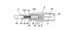
図1は同軸ケーブル及びコネクタカバーの取付構造を示す説明図である。図1に示すように、同軸ケーブル2は、先端から順に内部導体21、絶縁体22及び外部導体23が外部被覆24から露出している。内部導体21の先端部には、導体からなる中心ピン3が取り付けられている。また同軸ケーブル2の先端部には、外部導体23の少なくとも一部が覆われないように、内部導体21及び絶縁体22を覆う絶縁性の位置決め部4が取り付けられている。
FIG. 1 is an explanatory view showing a mounting structure of a coaxial cable and a connector cover. As shown in FIG. 1, in the
位置決め部4は、略円柱状の外形を有しており、その外径は同軸ケーブル2の外径よりも僅かに大きく設定されている。また、位置決め部4には、同軸ケーブル2の内部導体21及び中心ピン3に係合する係合部41と、係合部41よりも基端部側で隙間を空けて絶縁体22を覆う被覆部42とが設けられている。
The
コネクタカバー5は例えば金属等の導電性材料により形成されている。コネクタカバー5には、先端部から基端部にかけて貫通した貫通孔51が形成されている。貫通孔51における基端部52の内径は同軸ケーブル2の外径と略同径に設定されている。この貫通孔51の基端部52内部には、同軸ケーブル2の外部導体23が配置されている。ここで、コネクタカバー5の基端部52には、外部からプレスされたかしめ部53aが設けられており、このかしめ部53aによりコネクタカバー5と外部導体23との接触が固定されている。
The
貫通孔51における先端部55の内径は位置決め部4の外径よりも大きい径に設定されている。この貫通孔51の先端部55内部には、中心ピン3が配置されている。
貫通孔51における中間部54の内径は位置決め部4の外径と略同径に設定されている。貫通孔51の中間部54内部には、位置決め部4が配置されている。位置決め部4は、貫通孔51の中間部54内に挿入されると、被覆部42の端部が貫通孔51の基端部52と中間部54との境界に形成されている段部56に接触し係止される。これによって、コネクタカバー5と同軸ケーブル2との位置決めが行われる。また、コネクタカバー5の中間部54には、外部からプレスされたかしめ部53bが設けられており、このかしめ部53bによりコネクタカバー5と位置決め部4とが固定されている。
The inner diameter of the
The inner diameter of the
次に、ケーブル取付方法について説明する。
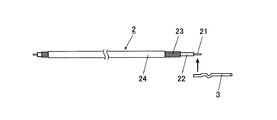
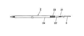
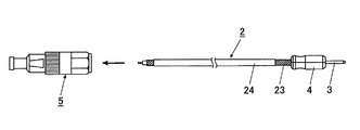
まず、図2,3に示すように、同軸ケーブル2の先端部から内部導体21、絶縁体22及び外部導体23を露出させてから(露出工程)、内部導体21に中心ピン3を半田付けして取り付ける。ここで、各部の露出長さは、上記した貫通孔51との位置関係が確保される長さに設定されている。
Next, a cable attachment method will be described.
First, as shown in FIGS. 2 and 3, the
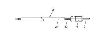
次いで、図4,5に示すように同軸ケーブル2の先端部に、外部導体23の少なくとも一部が露出するように位置決め部4を取り付ける(位置決め部取付工程)。位置決め部4は取り付け前においては径方向に二つに分割されていて、これらで同軸ケーブル2の内部導体21及び中心ピン3を挟んで組み付けることで、位置決め部4の取り付けが完了する。
Next, as shown in FIGS. 4 and 5, the
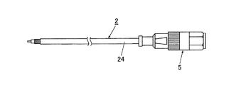
位置決め部取付工程の後には、図6に示すように同軸ケーブル2の基端部を、コネクタカバー5の先端部から貫通孔51に挿入する(挿入工程)。
After the positioning portion mounting step, the proximal end portion of the
挿入工程の後には、図7に示すように、位置決め部4の被覆部42の端部が、貫通孔51の基端部52と中間部54との境界に形成されている段部56に接触し係止されるまで、同軸ケーブル2をコネクタカバー5の基端部52から引き出す。この引き出しによって、位置決め部4が貫通孔51の中間部54内に挿入されると、貫通孔51の基端部52と中間部54との境界に形成されている段部56に接触し係止される。これでコネクタカバー5と同軸ケーブル2とが位置決めされ、貫通孔51の基端部52の内周面と、同軸ケーブル2の外部導体23とが対向配置される(位置決め工程:図1参照)。
After the insertion step, as shown in FIG. 7, the end portion of the covering
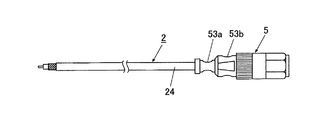
その後、図8に示すように、コネクタカバー5の基端部52と、中間部54とをそれぞれ外部からプレスし、かしめることで、かしめ部53a,53bを形成する(かしめ工程)。これにより、コネクタカバー5に対して、位置決め部4と外部導体23とがそれぞれ接触し、その状態が固定される。
Thereafter, as shown in FIG. 8, the
以上のように、コネクタカバー5の貫通孔51における基端部52の内径が、同軸ケーブル2の外径と略同径であるので、貫通孔51内に同軸ケーブル2を挿入すると、貫通孔51の基端部52内に外部導体23を配置することが可能となる。そして、同軸ケーブル2の位置決めを行うと、貫通孔51の基端部52の内周面と、同軸ケーブル2の外部導体23とが接触可能に対向配置される。その後、コネクタカバー5の基端部をかしめることでコネクタカバー5と外部導体23との接触が固定される。このように、外部導体23の接地を固定する部材を用いなくとも、外部導体23の接地を確保することができる。
また、同軸ケーブル2がコネクタカバー5の先端部55から貫通孔51に挿入されているので、その後においては位置決め部4が、貫通孔51の基端部52と中間部54との境界に形成されている段部56に接触し係止される。これにより、コネクタカバー5の基端部52側から同軸ケーブル2が抜けてしまうことを防止することができる。
なお、本発明は上記実施形態に限らず適宜変更可能である。
As described above, since the inner diameter of the
Further, since the
Note that the present invention is not limited to the above embodiment, and can be modified as appropriate.
2 同軸ケーブル
3 中心ピン
4 位置決め部
5 コネクタカバー
21 内部導体
22 絶縁体
23 外部導体
24 外部被覆
41 係合部
42 被覆部
51 貫通孔
52 基端部
53a かしめ部
53b かしめ部
54 中間部
55 基端部
56 段部
DESCRIPTION OF
Claims (1)
前記同軸ケーブルの先端部から内部導体及び外部導体を露出させる露出工程と、
前記貫通孔内に挿入されると前記貫通孔の基端部に係止され位置決めする位置決め部を、前記露出工程で露出した前記外部導体の少なくとも一部が覆われないように、前記同軸ケーブルの先端部に取り付ける位置決め部取付工程と、
前記位置決め部取付工程の後に、前記同軸ケーブルの基端部を前記コネクタカバーの先端部から前記貫通孔に挿入する挿入工程と、
前記挿入工程の後に、前記位置決め部が前記貫通孔の段部に係止されるように、前記コネクタカバーと前記同軸ケーブルとの位置決めを行うことで、前記貫通孔の基端部の内周面と、前記同軸ケーブルの外部導体とを対向配置する位置決め工程と、
前記コネクタカバーの基端部をかしめることで前記コネクタカバーと前記外部導体との接触を固定するかしめ工程とを有することを特徴とするケーブル取付方法。 A through hole penetrating from the distal end portion to the proximal end portion, wherein an inner diameter of the proximal end portion of the through hole is substantially the same as an outer diameter of the coaxial cable, and an inner diameter of the distal end portion of the through hole is the coaxial cable; A cable attachment method for attaching the coaxial cable to a connector cover having a diameter larger than the outer diameter of
An exposing step of exposing the inner conductor and the outer conductor from the tip of the coaxial cable;
A positioning portion that is locked and positioned at the base end portion of the through-hole when inserted into the through-hole is arranged so that at least a part of the outer conductor exposed in the exposing step is not covered. A positioning part attaching step to be attached to the tip part;
After the positioning portion mounting step, an insertion step of inserting the proximal end portion of the coaxial cable from the distal end portion of the connector cover into the through hole;
After the insertion step, the connector cover and the coaxial cable are positioned so that the positioning portion is locked to the stepped portion of the through hole, whereby the inner peripheral surface of the base end portion of the through hole And a positioning step of opposingly arranging the outer conductor of the coaxial cable;
A cable attachment method comprising: a caulking step for fixing contact between the connector cover and the outer conductor by caulking a base end portion of the connector cover.
Priority Applications (2)
| Application Number | Priority Date | Filing Date | Title |
|---|---|---|---|
| JP2008322034A JP4888481B2 (en) | 2008-12-18 | 2008-12-18 | Cable mounting method |
| EP09170146A EP2200132A1 (en) | 2008-12-18 | 2009-09-14 | Cable attaching method, method of manufacturing coaxial cable to which connector cover is attached, coaxial cable to which connector cover is attached |
Applications Claiming Priority (1)
| Application Number | Priority Date | Filing Date | Title |
|---|---|---|---|
| JP2008322034A JP4888481B2 (en) | 2008-12-18 | 2008-12-18 | Cable mounting method |
Publications (2)
| Publication Number | Publication Date |
|---|---|
| JP2010146836A true JP2010146836A (en) | 2010-07-01 |
| JP4888481B2 JP4888481B2 (en) | 2012-02-29 |
Family
ID=42041821
Family Applications (1)
| Application Number | Title | Priority Date | Filing Date |
|---|---|---|---|
| JP2008322034A Expired - Fee Related JP4888481B2 (en) | 2008-12-18 | 2008-12-18 | Cable mounting method |
Country Status (2)
| Country | Link |
|---|---|
| EP (1) | EP2200132A1 (en) |
| JP (1) | JP4888481B2 (en) |
Cited By (4)
| Publication number | Priority date | Publication date | Assignee | Title |
|---|---|---|---|---|
| WO2014186066A1 (en) * | 2013-05-13 | 2014-11-20 | Perfectvision Manufacturing, Inc | Coaxial cable connector with continuity bus |
| US9077089B2 (en) | 2013-05-13 | 2015-07-07 | Perfectvision Manufacturing, Inc | Coaxial cable connector with continuity bus |
| US9356364B2 (en) | 2013-05-13 | 2016-05-31 | Perfectvision Manufacturing Inc | Coaxial cable connector with continuity bus |
| US10027040B2 (en) | 2013-05-13 | 2018-07-17 | Perfectvision Manufacturing, Inc | Body clamp connector |
Families Citing this family (1)
| Publication number | Priority date | Publication date | Assignee | Title |
|---|---|---|---|---|
| KR101436507B1 (en) | 2013-04-24 | 2014-09-01 | 정봉균 | Patch plug |
Citations (3)
| Publication number | Priority date | Publication date | Assignee | Title |
|---|---|---|---|---|
| JPS6124983A (en) * | 1984-07-13 | 1986-02-03 | 川崎炉材株式会社 | Method of repairing kiln wall of industrial kiln |
| JPS6148584A (en) * | 1984-08-10 | 1986-03-10 | C Uyemura & Co Ltd | Scale remover |
| JPS6337092A (en) * | 1986-07-29 | 1988-02-17 | 株式会社日立ビルシステムサービス | Shut-off valve for cylinder of hydraulic elevator |
Family Cites Families (3)
| Publication number | Priority date | Publication date | Assignee | Title |
|---|---|---|---|---|
| US3828305A (en) * | 1973-03-30 | 1974-08-06 | Amp Inc | Terminal connector and method of attaching same to coaxial cable |
| JP2599993Y2 (en) | 1992-04-06 | 1999-09-27 | エスエムケイ株式会社 | Cable connector |
| DE102004024792B4 (en) * | 2004-05-17 | 2007-12-13 | Ims Connector Systems Gmbh | cable connectors |
-
2008
- 2008-12-18 JP JP2008322034A patent/JP4888481B2/en not_active Expired - Fee Related
-
2009
- 2009-09-14 EP EP09170146A patent/EP2200132A1/en not_active Withdrawn
Patent Citations (3)
| Publication number | Priority date | Publication date | Assignee | Title |
|---|---|---|---|---|
| JPS6124983A (en) * | 1984-07-13 | 1986-02-03 | 川崎炉材株式会社 | Method of repairing kiln wall of industrial kiln |
| JPS6148584A (en) * | 1984-08-10 | 1986-03-10 | C Uyemura & Co Ltd | Scale remover |
| JPS6337092A (en) * | 1986-07-29 | 1988-02-17 | 株式会社日立ビルシステムサービス | Shut-off valve for cylinder of hydraulic elevator |
Cited By (7)
| Publication number | Priority date | Publication date | Assignee | Title |
|---|---|---|---|---|
| WO2014186066A1 (en) * | 2013-05-13 | 2014-11-20 | Perfectvision Manufacturing, Inc | Coaxial cable connector with continuity bus |
| US9077089B2 (en) | 2013-05-13 | 2015-07-07 | Perfectvision Manufacturing, Inc | Coaxial cable connector with continuity bus |
| US9105988B2 (en) | 2013-05-13 | 2015-08-11 | Perfectvision Manufacturing, Inc. | Coaxial cable connector with continuity bus |
| US9356364B2 (en) | 2013-05-13 | 2016-05-31 | Perfectvision Manufacturing Inc | Coaxial cable connector with continuity bus |
| US10027040B2 (en) | 2013-05-13 | 2018-07-17 | Perfectvision Manufacturing, Inc | Body clamp connector |
| US10367274B2 (en) | 2013-05-13 | 2019-07-30 | Perfectvision Manufacturing, Inc | Body clamp connector |
| US11417969B2 (en) | 2013-05-13 | 2022-08-16 | Perfectvision Manufacturing, Inc. | Body clamp connector |
Also Published As
| Publication number | Publication date |
|---|---|
| JP4888481B2 (en) | 2012-02-29 |
| EP2200132A1 (en) | 2010-06-23 |
Similar Documents
| Publication | Publication Date | Title |
|---|---|---|
| JP5244427B2 (en) | Electronic component mounting / insulator-integrated inner conductor terminals and coaxial connectors | |
| US6837728B2 (en) | Equipment-mounting wire harness | |
| KR101177202B1 (en) | Coaxial connector and method for assembling coaxial connector | |
| JP2010268562A (en) | Structure of fixing shield cable and method for fixing the same | |
| JP4888481B2 (en) | Cable mounting method | |
| JP2008123913A (en) | Inner conductor terminal and coaxial connector | |
| JP2004146290A (en) | Water proof connector | |
| JP2007103268A (en) | Shield connector | |
| JP6616671B2 (en) | Cable assembly and method for manufacturing cable assembly | |
| JP4193133B2 (en) | L-type plug for coaxial connector and manufacturing method thereof | |
| JP4806692B2 (en) | Jack | |
| JP3094428U (en) | RF cable connection structure | |
| JP2006294514A (en) | Shield fitting and shield structure provided with shield fitting | |
| JP2011060425A (en) | Shield connector | |
| JP3693973B2 (en) | L-shaped plug and its assembly method | |
| JP3611700B2 (en) | Connector structure for shielded wire | |
| JP2012174654A (en) | Attachment structure of coaxial connector | |
| JP2001309543A (en) | Structure and method for connecting shielded wire | |
| JP4392144B2 (en) | Waterproof structure for earth | |
| JP2006012498A (en) | Coaxial plug | |
| JP2004186057A (en) | Coaxial connector | |
| JP2006351328A (en) | Coaxial cable connector | |
| JP2004095518A (en) | L type plug with semi-rigid cable, and its manufacturing method | |
| JP5058869B2 (en) | Coaxial connector and method of assembling coaxial connector | |
| JP3355124B2 (en) | Terminal connection structure |
Legal Events
| Date | Code | Title | Description |
|---|---|---|---|
| A977 | Report on retrieval |
Free format text: JAPANESE INTERMEDIATE CODE: A971007 Effective date: 20100921 |
|
| A131 | Notification of reasons for refusal |
Free format text: JAPANESE INTERMEDIATE CODE: A131 Effective date: 20100928 |
|
| A521 | Request for written amendment filed |
Free format text: JAPANESE INTERMEDIATE CODE: A523 Effective date: 20101126 |
|
| A131 | Notification of reasons for refusal |
Free format text: JAPANESE INTERMEDIATE CODE: A131 Effective date: 20110322 |
|
| A521 | Request for written amendment filed |
Free format text: JAPANESE INTERMEDIATE CODE: A523 Effective date: 20110520 |
|
| TRDD | Decision of grant or rejection written | ||
| A01 | Written decision to grant a patent or to grant a registration (utility model) |
Free format text: JAPANESE INTERMEDIATE CODE: A01 Effective date: 20111115 |
|
| A01 | Written decision to grant a patent or to grant a registration (utility model) |
Free format text: JAPANESE INTERMEDIATE CODE: A01 |
|
| A61 | First payment of annual fees (during grant procedure) |
Free format text: JAPANESE INTERMEDIATE CODE: A61 Effective date: 20111128 |
|
| R150 | Certificate of patent or registration of utility model |
Free format text: JAPANESE INTERMEDIATE CODE: R150 |
|
| FPAY | Renewal fee payment (event date is renewal date of database) |
Free format text: PAYMENT UNTIL: 20141222 Year of fee payment: 3 |
|
| LAPS | Cancellation because of no payment of annual fees |